EP2590258B1 - Mobile terminal and an antenna for the mobile terminal - Google Patents
Mobile terminal and an antenna for the mobile terminal Download PDFInfo
- Publication number
- EP2590258B1 EP2590258B1 EP12006478.7A EP12006478A EP2590258B1 EP 2590258 B1 EP2590258 B1 EP 2590258B1 EP 12006478 A EP12006478 A EP 12006478A EP 2590258 B1 EP2590258 B1 EP 2590258B1
- Authority
- EP
- European Patent Office
- Prior art keywords
- mobile terminal
- carrier
- coupling member
- radiator
- connector portion
- Prior art date
- Legal status (The legal status is an assumption and is not a legal conclusion. Google has not performed a legal analysis and makes no representation as to the accuracy of the status listed.)
- Not-in-force
Links
- 238000010168 coupling process Methods 0.000 claims description 82
- 238000005859 coupling reaction Methods 0.000 claims description 82
- 230000008878 coupling Effects 0.000 claims description 81
- 238000000034 method Methods 0.000 claims description 10
- 230000008859 change Effects 0.000 claims description 8
- 230000008569 process Effects 0.000 claims description 7
- 238000004891 communication Methods 0.000 description 25
- 230000006870 function Effects 0.000 description 14
- 230000000694 effects Effects 0.000 description 10
- 238000010295 mobile communication Methods 0.000 description 8
- 230000005236 sound signal Effects 0.000 description 6
- 230000004308 accommodation Effects 0.000 description 5
- 230000009471 action Effects 0.000 description 5
- 238000005516 engineering process Methods 0.000 description 5
- 230000006872 improvement Effects 0.000 description 5
- 239000000463 material Substances 0.000 description 5
- 239000007769 metal material Substances 0.000 description 5
- 239000004020 conductor Substances 0.000 description 4
- 238000012545 processing Methods 0.000 description 4
- 230000004888 barrier function Effects 0.000 description 3
- 238000010586 diagram Methods 0.000 description 3
- 238000003825 pressing Methods 0.000 description 3
- 238000010521 absorption reaction Methods 0.000 description 2
- 230000008901 benefit Effects 0.000 description 2
- 230000005540 biological transmission Effects 0.000 description 2
- 230000015556 catabolic process Effects 0.000 description 2
- 238000006731 degradation reaction Methods 0.000 description 2
- 239000003989 dielectric material Substances 0.000 description 2
- 238000002347 injection Methods 0.000 description 2
- 239000007924 injection Substances 0.000 description 2
- 239000004973 liquid crystal related substance Substances 0.000 description 2
- 230000007774 longterm Effects 0.000 description 2
- 229910001220 stainless steel Inorganic materials 0.000 description 2
- 239000010935 stainless steel Substances 0.000 description 2
- 230000003068 static effect Effects 0.000 description 2
- 229920003002 synthetic resin Polymers 0.000 description 2
- 239000000057 synthetic resin Substances 0.000 description 2
- 239000010936 titanium Substances 0.000 description 2
- RTAQQCXQSZGOHL-UHFFFAOYSA-N Titanium Chemical compound [Ti] RTAQQCXQSZGOHL-UHFFFAOYSA-N 0.000 description 1
- 230000001133 acceleration Effects 0.000 description 1
- XAGFODPZIPBFFR-UHFFFAOYSA-N aluminium Chemical compound [Al] XAGFODPZIPBFFR-UHFFFAOYSA-N 0.000 description 1
- 229910052782 aluminium Inorganic materials 0.000 description 1
- 238000013459 approach Methods 0.000 description 1
- 238000003491 array Methods 0.000 description 1
- 238000001816 cooling Methods 0.000 description 1
- 230000001186 cumulative effect Effects 0.000 description 1
- 230000000593 degrading effect Effects 0.000 description 1
- 238000011161 development Methods 0.000 description 1
- 230000005684 electric field Effects 0.000 description 1
- 230000005672 electromagnetic field Effects 0.000 description 1
- 239000010408 film Substances 0.000 description 1
- 238000001746 injection moulding Methods 0.000 description 1
- 238000005259 measurement Methods 0.000 description 1
- 230000007246 mechanism Effects 0.000 description 1
- 238000012986 modification Methods 0.000 description 1
- 230000004048 modification Effects 0.000 description 1
- 238000003032 molecular docking Methods 0.000 description 1
- 230000003387 muscular Effects 0.000 description 1
- 230000006855 networking Effects 0.000 description 1
- 230000003287 optical effect Effects 0.000 description 1
- 230000010355 oscillation Effects 0.000 description 1
- 238000003909 pattern recognition Methods 0.000 description 1
- 238000007747 plating Methods 0.000 description 1
- 238000007639 printing Methods 0.000 description 1
- 230000004044 response Effects 0.000 description 1
- 229910000679 solder Inorganic materials 0.000 description 1
- 239000010409 thin film Substances 0.000 description 1
- 229910052719 titanium Inorganic materials 0.000 description 1
- 230000007704 transition Effects 0.000 description 1
Images


Classifications
-
- H—ELECTRICITY
- H04—ELECTRIC COMMUNICATION TECHNIQUE
- H04B—TRANSMISSION
- H04B1/00—Details of transmission systems, not covered by a single one of groups H04B3/00 - H04B13/00; Details of transmission systems not characterised by the medium used for transmission
- H04B1/38—Transceivers, i.e. devices in which transmitter and receiver form a structural unit and in which at least one part is used for functions of transmitting and receiving
-
- H—ELECTRICITY
- H01—ELECTRIC ELEMENTS
- H01Q—ANTENNAS, i.e. RADIO AERIALS
- H01Q1/00—Details of, or arrangements associated with, antennas
- H01Q1/12—Supports; Mounting means
- H01Q1/22—Supports; Mounting means by structural association with other equipment or articles
- H01Q1/24—Supports; Mounting means by structural association with other equipment or articles with receiving set
- H01Q1/241—Supports; Mounting means by structural association with other equipment or articles with receiving set used in mobile communications, e.g. GSM
- H01Q1/242—Supports; Mounting means by structural association with other equipment or articles with receiving set used in mobile communications, e.g. GSM specially adapted for hand-held use
- H01Q1/243—Supports; Mounting means by structural association with other equipment or articles with receiving set used in mobile communications, e.g. GSM specially adapted for hand-held use with built-in antennas
-
- H—ELECTRICITY
- H01—ELECTRIC ELEMENTS
- H01Q—ANTENNAS, i.e. RADIO AERIALS
- H01Q1/00—Details of, or arrangements associated with, antennas
- H01Q1/12—Supports; Mounting means
- H01Q1/22—Supports; Mounting means by structural association with other equipment or articles
- H01Q1/24—Supports; Mounting means by structural association with other equipment or articles with receiving set
-
- H—ELECTRICITY
- H01—ELECTRIC ELEMENTS
- H01Q—ANTENNAS, i.e. RADIO AERIALS
- H01Q9/00—Electrically-short antennas having dimensions not more than twice the operating wavelength and consisting of conductive active radiating elements
- H01Q9/04—Resonant antennas
- H01Q9/0407—Substantially flat resonant element parallel to ground plane, e.g. patch antenna
- H01Q9/0442—Substantially flat resonant element parallel to ground plane, e.g. patch antenna with particular tuning means
-
- H—ELECTRICITY
- H04—ELECTRIC COMMUNICATION TECHNIQUE
- H04M—TELEPHONIC COMMUNICATION
- H04M1/00—Substation equipment, e.g. for use by subscribers
- H04M1/02—Constructional features of telephone sets
Definitions
- the present invention relates to an antenna for transmitting and receiving radio signals.
- the present invention is suitable for a wide scope of applications, it is particularly suitable for implementation in a mobile terminal.
- Mobile terminals are presently configured to perform various functions. Such functions include data and voice communications, capturing still images and video via a camera, recording audio, playing music files and outputting music via a speaker system, and displaying images and video on a display. Some mobile terminals include additional functionality that supports game playing, while other mobile terminals are also configured as multimedia players. More recently, mobile terminals have been configured to receive broadcast and multicast signals that permit viewing of content, such as videos and television programs.
- terminals can be classified into mobile terminals and stationary terminals based on a presence or non-presence of mobility.
- Mobile terminals can also be classified into handheld terminals and vehicle mounted terminals based on whether they are configured to be carried by hand.
- a User interface (Ul) environment is provided in a mobile terminal to enable a user to easily and conveniently search for, or select, a desired function.
- Hardware improvements may include structural changes and improvements that allow a user to use a mobile terminal in a more convenient manner.
- structural changes and improvements may be made to an antenna of the mobile terminal.
- the mobile terminal antennas transmit and receives electric waves for radio communication and should be designed to implement multiple bandwidths for satisfying various functions such as voice call, Wibro® and digital multimedia broadcasting (DMB).
- the antennas should also be miniaturized so as to be mounted in the mobile terminal and to reduce the amount of space occupied by the antennas.
- mobile terminal antennas have complicated structures and it is difficult to independently control parameter values that determine antenna characteristics such as resonance frequency, bandwidth and gain.
- Mobile terminals often include a connector portion for connection with a connector of an external device.
- the connector portion is often disposed at one end of a terminal body of the mobile terminal and is exposed to the outside.
- the antenna is also disposed at one end of the terminal body to aid in reducing Specific Absorption Rate (SAR).
- SAR Specific Absorption Rate
- the connector portion is often formed of a metallic material, the antenna characteristics may be influenced by the connector portion. Therefore, the antenna should be spaced from the connector portion in order to minimize the influence.
- US2006/0089184 A1 discloses a built-in antenna module for a portable wireless terminal, comprising an antenna carrier to allow a distance between a radiator and a mainboard, the antenna carrier including a plate type junction panel to which the radiator is fixed, an outer barrier rib extending along an edge of the junction panel with a uniform height, and at least one compartment barrier rib for dividing a space formed by the junction panel and the outer barrier rib.
- a mobile terminal of the present invention preferably includes a terminal body, an antenna module coupled to the terminal body, the antenna module including a radiator configured for transmitting and receiving radio signals, a circuit board electrically coupled to the antenna module and configured to process the transmitted and received radio signals, and at least one coupling member positioned proximate to and spaced from the radiator a particular distance.
- the at least one coupling member may be coupled to the radiator and configured for coupling the antenna module to the terminal body.
- the antenna module further includes a carrier positioned proximate to a first end of the terminal body and the radiator is positioned on at least a first surface of the carrier.
- the at least one coupling member extends through the carrier from the first surface to a second surface opposite the first surface.
- the carrier defines at least one opening that includes a recess in the first surface having a depth less than a thickness of the carrier, the thickness of the carrier measured from the first surface to a second surface of the carrier opposite the first surface, and an aperture extending from a bottom surface of the recess to the second surface of the carrier
- each of the at least one coupling member includes a head portion positioned in the recess of a corresponding opening of the at least one opening, a bottom surface of the head portion configured to couple with the bottom surface of the recess, and a body portion positioned in the aperture of the corresponding opening; and the body portion of the at least one coupling member is configured to couple with the terminal body.
- At least a portion of the radiator surrounds at least a portion of a perimeter of the recess of an opening of the at least one opening.
- a connector portion positioned at the first end of the terminal body and electrically coupled to the circuit board, the connector portion including a terminal configured for electrically coupling with a connector of an external device, wherein the carrier is positioned to cover the connector portion such that the connector portion is positioned between the carrier and the terminal body, and the carrier applies pressure to the connector portion to restrict movement of the connector portion.
- the at least one coupling member is configured to increase the pressure applied by the carrier to the connector portion when pressure applied by the bottom surface of the at least one coupling member against the bottom surface of the recess of the corresponding opening is increased.
- the at least one coupling member includes a first screw and a second screw, the first screw is positioned proximate a first side of the connector portion, and the second screw is positioned proximate a second side of the connector portion.
- At least a portion of the radiator includes a varying width for transmitting and receiving radio signals on different frequency bands.
- the at least one coupling member includes a first screw and a second screw, and the first screw and the second screw are spaced apart from each other.
- the first screw is configured to resonate at a high frequency band of the different frequency bands
- the second screw is configured to resonate at a low frequency band of the different frequency bands.
- the terminal body includes a case formed of a dielectric material, the case forms an outer appearance of the terminal body, and the at least one coupling member is coupled to the case.
- the particular distance is 3.0 mm or less.
- the at least one coupling member is coupled to the radiator and is further configured to change a resonance frequency of the antenna module.
- the radiator is further positioned in at least a portion of an opening of the at least one opening to surround at least a portion of a coupling member of the at least one coupling member.
- a transmission frequency of the radiator includes a frequency band corresponding to a personal communication system (PCS), an advanced wireless service (AWS), a digital communications network (DCN), or a long term evolution (LTE).
- the mobile terminal further includes a speaker positioned within an inner space of the carrier, wherein the inner space of the carrier is configured to resonate sound output from the speaker.
- the carrier includes a first region including the first surface of the carrier, and a second region positioned spaced from the first region and including the inner space, wherein the radiator is patterned on the first surface of the carrier.
- the first region of the carrier extends in a lateral direction of the terminal body proximate the first end of the terminal body, the second region of the carrier extends along a first side of the terminal body and away from the first end of the terminal body.
- the suffixes "module” and “unit” are used for facilitation of the detailed description of the present invention and do not have meanings or functions different from each other. Therefore, significant meanings or roles are not given to the suffixes themselves and it is understood that the terms 'module' and 'unit' can be used together or interchangeably.
- the present invention can be applicable to various types of terminals.
- Examples of such terminals include mobile as well as stationary terminals, such as mobile phones, user equipment, smart phones, DTV, computers, digital broadcast terminals, personal digital assistants, portable multimedia players (PMP), E-books, and navigation systems.
- mobile phones such as mobile phones, user equipment, smart phones, DTV, computers, digital broadcast terminals, personal digital assistants, portable multimedia players (PMP), E-books, and navigation systems.
- FIG. 1 is a block diagram of a mobile terminal 100 in accordance with an embodiment of the present invention.
- the mobile terminal 100 includes a wireless communication unit 110, an audio/video (AN) input unit 120, a user input unit 130, a sensing unit 140, an output unit 150, a memory 160, an interface unit 170, a controller 180, and a power supply unit 190.
- FIG. 1 shows the mobile terminal 100 having various components, it is understood that implementing all of the illustrated components is not a requirement. More or fewer components may alternatively be implemented.
- the wireless communication unit 110 includes one or more components that permit wireless communication between the mobile terminal 100 and a wireless communication system or a network within which the mobile terminal 100 is located.
- the wireless communication unit 110 includes a broadcast receiving module 111, a mobile communication module 112, a wireless Internet module 113, a short-range communication module 114 and a location information module 115.
- the wireless communication unit 110 may be replaced with a wired communication unit.
- the wireless communication unit 110 and a wired communication unit (not shown) may be commonly referred to as a communication unit.
- the broadcast receiving module 111 receives a broadcast signal and/or broadcast associated information from an external broadcast managing entity via a broadcast channel.
- the broadcast channel may include a satellite channel and/or a terrestrial channel.
- the broadcast managing entity may refer to a system that transmits a broadcast signal and/or broadcast associated information.
- the broadcast managing entity may be a server that generates and transmits broadcast signals and/or broadcast associated information or a server for receiving previously generated broadcast signals and/or broadcast-related information and transmitting the broadcast signals and/or the broadcast associated information to the mobile terminal 100.
- the broadcast signals may include not only TV broadcast signals, radio broadcast signals, and data broadcast signals, but also signals in the form of a TV broadcast signal combined with a radio broadcast signal.
- the broadcast associated information may be information about a broadcast channel, a broadcast program, or a broadcast service provider.
- the broadcast associated information may even be provided over a mobile communication network, in which case the broadcast associated information may be received via the mobile communication module 112.
- Examples of broadcast associated information include an electronic program guide (EPG) of digital multimedia broadcasting (DMB) and an electronic service guide (ESG) of digital video broadcast-handheld (DVB-H).
- the broadcast receiving module 111 may receive broadcast signals transmitted from various types of broadcast systems.
- the broadcast systems include digital multimedia broadcasting-terrestrial (DMB-T), digital multimedia broadcasting-satellite (DMB-S), digital video broadcast-handheld (DVB-H), a data broadcasting system known as media forward link only (MediaFLO®) and integrated services digital broadcast-terrestrial (ISDB-T).
- the broadcast receiving module 111 may also receive multicast signals.
- the broadcast signals and/or the broadcast associated information received by the broadcast receiving module 111 may be stored in a suitable storage device, such as in the memory 160.
- the mobile communication module 112 transmits/receives wireless signals to/from at least one of a base station, an external terminal or a server over a mobile communication network.
- the wireless signals may represent, for example, voice call signals, video telephony call signals or data in various forms according to the transmission/reception of text and/or multimedia messages.
- the wireless Internet module 113 supports Internet access for the mobile terminal 100.
- the wireless Internet module 113 may be internally or externally coupled to the mobile terminal 100.
- Suitable technologies for wireless Internet include, but are not limited to, WLAN (Wireless LAN), Wi-Fi®, Wibro® (Wireless broadband), Wimax® (World Interoperability for Microwave Access), and HSDPA (High Speed Downlink Packet Access).
- the wireless Internet module 113 may be replaced with a wired Internet module (not shown) in non-mobile terminals.
- the wireless Internet module 113 and the wired Internet module may be commonly referred to as an Internet module.
- the wireless Internet module 113 can receive or download the data relevant to the area in which the mobile terminal 100 is located from the external server.
- the short-range communication module 114 facilitates relatively short-range communications.
- Suitable technologies for short-range communication include, but are not limited to, radio frequency identification (RFID), infrared data association (IrDA), ultra-wideband (UWB), as well as networking technologies such as Bluetooth® and ZigBee®.
- RFID radio frequency identification
- IrDA infrared data association
- UWB ultra-wideband
- networking technologies such as Bluetooth® and ZigBee®.
- the location information module 115 identifies or otherwise obtains a location of the mobile terminal 100.
- the location information module 115 may obtain position information by using a global navigation satellite system (GNSS).
- GNSS is a term used to describe radio navigation satellite systems configured to send reference signals capable of determining their positions on the surface of the earth or near the surface of the earth while revolving around the earth.
- the GNSS includes: a global position system (GPS) operated by the U.S.A.; Galileo operated by Europe; a global orbiting navigational satellite system (GLONASS) operated by Russia; Compass operated by China; and a quasi-zenith satellite system (QZSS) operated by Japan.
- GPS global position system
- GLONASS global orbiting navigational satellite system
- QZSS quasi-zenith satellite system
- the location information module 115 is a GPS module.
- the location information module 115 may calculate information related to distances between one point or object and at least three satellites and information related to the time when the distance information was measured and apply trigonometry to the obtained distance information to obtain three-dimensional position information on the point or object according to the latitude, longitude, and altitude at a predetermined time. Furthermore, a method of calculating position and time information using three satellites and correcting the calculated position and time information using another satellite may also used.
- the location information module 115 continues to calculate a current position in real time and to calculate velocity information based on the position information.
- the audio/video (A/V) input unit 120 may be configured to provide audio or video signal input to the mobile terminal 100.
- the A/V input unit 120 may include a camera 121 and a microphone 122.
- the camera 121 processes image frames of still pictures or video obtained by an image sensor in a photographing mode or a video telephony mode. The processed image frames may be displayed on a display unit 151.
- the image frames processed by the camera 121 may be stored in the memory 160 or transmitted to an external device through the wireless communication unit 110.
- the mobile terminal 100 can include two or more cameras 121, if appropriate.
- the microphone 122 receives an external audio signal while the mobile terminal 100 is in a particular mode, such as a phone call mode, a recording mode and/or a voice recognition mode.
- the received audio signal is processed and converted into digital data.
- the processed digital data is transformed into a format transmittable to a mobile communication base station via the mobile communication module 112 and then output.
- the mobile terminal 100, and in particular the A/V input unit 120 may include a noise removing algorithm to remove noise generated during the course of receiving the external audio signal.
- the user input unit 130 generates input data in response to user manipulation of an associated input device or devices. Examples of such devices include a keypad, a dome switch, a static pressure/capacitance touchpad, a jog wheel and a jog switch.
- a specific example of the user input unit 130 is a touch screen in which a touchpad is combined with a display, as will be described below.
- the sensing unit 140 provides status measurements of various aspects of the mobile terminal 100.
- the sensing unit 140 may detect an open/closed status of the mobile terminal 100, relative positioning of components, such as a display and a keypad of the mobile terminal 100, a change of position of the mobile terminal 100 or a component of the mobile terminal 100, a presence or absence of user contact with the mobile terminal 100, an orientation of the mobile terminal 100 and/or acceleration/deceleration of the mobile terminal 100.
- the mobile terminal 100 may be configured as a slide-type mobile terminal in which the sensing unit 140 may sense whether a sliding portion of the mobile terminal 100 is open or closed.
- the sensing unit 140 may also sense a presence or absence of power provided by the power supply unit 190 or a presence or absence of a coupling or other connection between the interface unit 170 and an external device.
- the sensing unit 140 may include a proximity sensor 141.
- the output unit 150 generates output relevant to the senses of sight, hearing and touch.
- the output unit 150 may include a display unit 151, an audio output module 152, an alarm unit 153, and a haptic module 154.
- the display unit 151 displays information processed by the mobile terminal 100. For example, when the mobile terminal 100 is in a call mode, the display unit 151 may display a user interface (UI) or a graphic user interface (GUI) associated with the call. If the mobile terminal 100 is in a video communication mode or a photograph mode, the display unit 151 may display a photographed and/or received picture, a UI or a GUI.
- UI user interface
- GUI graphic user interface
- the display unit 151 may include a liquid crystal display (LCD), a thin film transistor liquid crystal display (TFT LCD), an organic light-emitting diode (OLED), a flexible display, or a 3-dimensional display.
- the mobile terminal 100 may include one or more of such displays.
- the display unit 151 may have a transparent or light-transmittive type configuration, hereinafter referred to as a transparent display.
- a transparent OLED (TOLED) is an example of a transparent display.
- a rear configuration of the display unit 151 may also have the light-transmittive type configuration. In this configuration, a user is able to see an object located behind the terminal body via the area occupied by the display unit 151 of the terminal body.
- At least two display units 151 may be provided.
- a plurality of display units 151 may be provided on a single face of the mobile terminal 100 spaced apart from each other or built in one body.
- each of a plurality of display units 151 may be provided on different faces of the mobile terminal 100.
- the display unit 151 and a sensor for detecting a touch action are constructed in a mutual-layered structure (hereafter referred to as a 'touch screen')
- the display unit 151 may be used as an input device and an output device.
- the touch sensor may include a touch film, a touch sheet or a touchpad.
- the touch sensor can be configured to convert a pressure applied to a specific portion of the display unit 151 or a variation of electrostatic capacity generated from a specific portion of the display unit 151 to an electric input signal.
- the touch sensor may detect a pressure of a touch as well as a touched position or magnitude of the touch.
- a touch input is made to the touch sensor, a signal(s) corresponding to the touch input is transferred to a touch controller (not shown).
- the touch controller processes the signal(s) and then transfers corresponding data to the controller 180.
- the controller 180 may determine which portion of the display unit 151 is touched.
- a proximity sensor 141 can be provided within the mobile terminal 100 enclosed by the touch screen or around the touch screen.
- the proximity sensor 141 may detect a presence or non-presence of an object approaching a specific detecting surface or an object existing around the proximity sensor 141 using an electromagnetic field strength or infrared ray without mechanical contact. Accordingly, the proximity sensor 141 may have greater durability and greater utility than a contact type sensor.
- the proximity sensor 141 can include a transmittive photoelectric sensor, a direct reflective photoelectric sensor, a mirror reflective photoelectric sensor, a radio frequency oscillation proximity sensor, an electrostatic capacity proximity sensor, a magnetic proximity sensor or an infrared proximity sensor. If the touch screen is an electrostatic type touch screen, the proximity sensor 141 may detect proximity of a pointer using a variation of an electric field according to the proximity of the pointer and the touch screen or touch sensor may be classified as the proximity sensor 141.
- a 'proximity touch' An action in which a pointer approaches the touch screen without contacting the touch screen, yet is recognized as being located on the touch screen, is referred to as a 'proximity touch'.
- An action in which the pointer actually touches the touch screen is referred to as a 'contact touch'.
- the position on the touch screen proximity-touched by the pointer refers to the position of the pointer that vertically opposes the touch screen when the pointer performs the proximity touch.
- the proximity sensor 141 may detect a proximity touch and/or a proximity touch pattern, such as proximity touch distance, proximity touch duration, proximity touch position or proximity touch shift state. Information corresponding to the detected proximity touch action and/or the detected proximity touch pattern may be displayed on the touch screen.
- the audio output module 152 may output audio data that is received from the wireless communication unit 110 in, for example, a call-receiving mode, a call-placing mode, a recording mode, a voice recognition mode or a broadcast receiving mode.
- the audio output module 152 may output audio data stored in the memory 160.
- the audio output module 152 may output an audio signal relevant to a function, such as a call signal receiving sound, or a message receiving sound performed by the mobile terminal 100.
- the audio output module 152 may include, for example, a receiver, a speaker or a buzzer.
- the alarm unit 153 outputs a signal for announcing an occurrence of a particular event associated with the mobile terminal 100.
- Typical events include a call signal reception, a message reception, a key signal input and a touch input.
- the alarm unit 153 may output a signal for announcing the event occurrence via vibration as well as a video signal or an audio signal.
- the video signal is output via the display unit 151 and the audio signal is output via the audio output module 152. Therefore, at least the display unit 151 or the audio output module 152 can be regarded as part of the alarm unit 153.
- the haptic module 154 may generate various haptic effects that can be sensed by a user. Vibration is a representative tactile effect generated by the haptic module 154. Strength and pattern of the vibration generated from the haptic module 154 may be controllable. For example, vibrations differing from each other can be output by being synthesized together or can be output in sequence.
- the haptic module 154 may generate various haptic effects in addition to vibration.
- the haptic module 154 may generate an effect caused by a pin array vertically moving against skin being touched, an air injection force via an injection hole, an air suction force via a suction hole, an effect of skimming on a skin surface, an effect of contact with an electrode, an effect of electrostatic power and/or an effect of a hot/cold sense using an endothermic or exothermic device.
- the haptic module 154 can be configured to provide the haptic effect via direct contact.
- the haptic module 154 can also be configured to enable a user to experience the haptic effect via muscular sense of a finger or an arm.
- Two or more haptic modules 154 can be provided according to a configuration of the mobile terminal 100.
- the memory 160 is generally used to store various types of data for supporting the processing, control, and storage requirements of the mobile terminal 100. Examples of such data include program instructions for applications operating on the mobile terminal 100, contact data, phonebook data, messages, audio, still pictures, and moving pictures. A recent use history or a cumulative use frequency of each data, such as use frequency for each phonebook, each message or each multimedia, may be stored in the memory 160. Moreover, data for various patterns of vibration and/or sound to be output when a touch input is received at the touch screen may be stored in the memory 160.
- the memory 160 may include, for example, a flash memory, a hard disk, a multimedia card micro type memory, a random access memory (RAM), a static random access memory (SRAM), a read-only memory (ROM), an electrically erasable programmable read-only memory (EEPROM), a programmable read-only memory (PROM), a magnetic memory, a magnetic disk an optical disk, or a card type memory, such as SD memory or XD memory.
- the mobile terminal 100 may operate in association with a web storage that performs a storage function of the memory 160 via the Internet.
- the interface unit 170 couples the mobile terminal 100 with external devices.
- the interface unit 170 receives data from an external device.
- the interface unit 170 is supplied with power and may be configured to deliver the power to elements within the mobile terminal 100.
- the identity module is a chip or card that stores various types of information for authenticating a use authority of the mobile terminal 100 and can include a user identity module (UIM), a subscriber identity module (SIM) and/or a universal subscriber identity module (USIM).
- a device provided with the above identity module (hereafter referred to as an 'identity device') may be manufactured in the form of a smart card.
- the identity device is connectable to the mobile terminal 100 via a corresponding port.
- the interface unit 170 may be configured as a passage for supplying power to the mobile terminal 100 from a cradle that is connected to the mobile terminal 100.
- the interface unit 170 may facilitate delivery of various command signals, which are input via the cradle by a user, to the mobile terminal 100.
- Various command signals input via the cradle or the power may provide an indication for recognizing that the mobile terminal 100 is correctly loaded in the cradle.
- the controller 180 typically controls the overall operations of the mobile terminal 100. For example, the controller 180 performs control and processing associated with voice calls, data communications and video conferences.
- the controller 180 may include a multimedia module 184 that provides multimedia playback.
- the multimedia module 184 may be configured as part of the controller 180 or may be configured as a separate component.
- the controller 180 may also perform pattern recognition processing for recognizing a handwriting input performed on the touch screen as a character and/or recognizing a picture drawing input performed on the touch screen as characters or images.
- the power supply unit 190 provides power required by the various components of the mobile terminal 100.
- the power may be internal power, external power, or combinations thereof.
- Embodiments of the present invention described in the following description may be implemented within a recording medium that can be read by a computer or a computer-like device using software, hardware or combinations thereof.
- arrangements and embodiments may be implemented using at least one of application specific integrated circuits (ASICs), digital signal processors (DSPs), digital signal processing devices (DSPDs), programmable logic devices (PLDs), field programmable gate arrays (FPGAs), processors, controllers, microcontrollers, microprocessors or electrical units for performing other functions.
- ASICs application specific integrated circuits
- DSPs digital signal processors
- DSPDs digital signal processing devices
- PLDs programmable logic devices
- FPGAs field programmable gate arrays
- processors controllers, microcontrollers, microprocessors or electrical units for performing other functions.
- controller 180 may also be implemented by the controller 180.
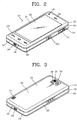
- FIG. 2 is a front perspective view showing an example of a front of the mobile terminal 100.
- the mobile terminal 100 of FIG. 2 is depicted as a bar-type terminal body.
- the mobile terminal 100 may be implemented in a variety of different configurations.
- the mobile terminal 100 includes a case, such as a casing, housing, or cover, that forms an exterior of the mobile terminal.
- the case may be divided into a front case 101 and a rear case 102.
- Various electric/electronic parts are provided in a space between the front case 101 and the rear case 102.
- a middle case may be further provided between the front case 101 and the rear case 102.
- the cases can be formed by injection molding of synthetic resin or may be formed of a metallic material, such as stainless steel (STS), aluminum (Al) or titanium (Ti).
- the display unit 151, audio output module 152, camera 121, first and second user manipulating units 130a and 130b, microphone 122 and/or the interface unit 170 can be provided on the terminal body, and more particularly on the front case 101.
- the display unit 151 occupies most of a main face of the front case 101.
- the audio output module 152 and the camera 121 may be provided at an area adjacent to one end portion of the display unit 151, while the first manipulating unit 130a and the microphone 122 may be provided at an area adjacent to the other, opposite end portion of the display unit 151.
- the second manipulating unit 130b and the interface unit 170 can be provided on lateral sides of the front and rear cases 101 and 102.
- the user input unit 130 may receive a command for controlling an operation of the mobile terminal 100.
- the user input unit 130 may include a plurality of manipulating units, such as the first and second manipulating units 130a and 130b.
- the first and second user manipulating units 130a and 130b can be named a manipulating portion and may adopt any mechanism of a tactile manner that enables a user to perform a manipulation action by experiencing a tactile feeling.
- Content input via the first manipulating unit 130a or the second manipulating unit 130b can be set to be different.
- commands such as start, end and scroll can be input via the first manipulating unit 130a.
- Commands for adjusting volume of sound output from the audio output module 152 and for switching the display unit 151 to a touch recognizing mode can be input via the second manipulating unit 130b.
- Many other such configurations may be contemplated.
- FIG. 3 is a rear perspective diagram of the mobile terminal 100 shown in FIG. 2 .
- Other embodiments, configurations and arrangements may also be provided.
- an additional camera 121' can be provided on a rear side of the terminal body, and more particularly, on the rear case 102.
- the camera 121' on the rear case 102 has a photographing direction that is substantially opposite to that of the camera 121 shown in FIG. 2 and may have a different resolution.
- the camera 121 may use a smaller number of pixels than the camera 121', and thereby have a relatively lower resolution, to capture and transmit an image of the user's face for a video call.
- the camera 121' may use a greater number of pixels than the camera 121, and thereby have a relatively greater resolution in general, for capturing an image of a general subject for photography without transmitting the captured image.
- the cameras 121 and 121' may be capable of being rotated in relation to the terminal body or to pop-up from the terminal body.
- a flash 123 and a mirror 124 may be disposed adjacent to the camera 121'.
- the flash 123 projects light toward a subject when photographing the subject using the camera 121'.
- the mirror 124 enables the user to view his/her face reflected by the mirror 124.
- An additional audio output module 152' can be disposed at the rear side of the terminal body.
- the additional audio output module 152' facilitates a stereo function in conjunction with the audio output module 152 illustrated in FIG. 2 and may be used for implementation of a speakerphone mode when communicating via the mobile terminal 100.
- the power supply unit 190 for supplying power to the mobile terminal 100 may be provided in the terminal body.
- the power supply unit 190 can be configured to be built within the terminal body or to be detachably connected to the terminal body.
- the terminal body includes a connector portion 230 positioned at one end, such as a first end 106, of the terminal body.
- the connector portion 230 is an example of the interface unit 170 which connects the mobile terminal 100 to an external device.
- the connector portion 230 may be a data port for transmitting and receiving data to/from an external device, or a power port for receiving power from the outside.
- Antennas may be disposed in the terminal body.
- the mobile terminal 100 may include an antenna for mobile communication and an antenna for receiving broadcasting signals or wireless Internet signals.
- the antennas may be combined together to integrally provide various wireless communication services.
- FIG. 4 is a disassembled perspective view of the mobile terminal 100 of FIG. 3 .
- a circuit board 181 is positioned within the terminal body.
- the circuit board 181 may be mounted to the front case 101 or the rear case 102, or to an additional inner structure.
- the circuit board 181 is depicted as covered by an inner surface of the rear case 102.
- the circuit board 181 may also include a shield member 182 for protecting the electronic devices mounted on the circuit board 181.
- the shield member 182 may be a metallic plate.
- the circuit board 181 is an example of the controller 180 ( FIG. 1 ) for operating various components of the mobile terminal 100.
- the mobile terminal may include a plurality of circuit boards 181 and the combination of the plurality of circuit boards may function as the controller 180.
- the circuit board 181 is electrically coupled to an antenna device 200 and processes a radio signal corresponding to a radio electromagnetic wave transceived by the antenna device 200.
- the rear case 102 may include a recessed accommodation portion 192 for accommodating a battery 191.
- the accommodation portion 192 may include an open bottom surface through which the shield member 182 is exposed to the outside of the mobile terminal 100 when the battery 191 is removed. In this manner, the shield member 182 forms the bottom of the accommodation portion 192.
- the battery 191 and the accommodation portion 192 are an example of the power supply unit 190 ( FIG. 1 ).
- a battery cover 103 for covering the battery 191 and the accommodation portion 192 may be detachably mounted to the rear case 102.
- the battery cover 103 is an example of the case that forms the outer appearance of the terminal body and may cover the entire rear surface 108 of the mobile terminal.
- the connector portion 230 When the connector portion 230 is positioned at the first end 106 of the terminal body, the connector portion may be positioned proximate to the microphone 122.
- the mobile terminal 100 may be coupled to external devices, such as a computer, a printer, a multimedia device, or a memory device via a data cable coupled to the connector portion 230.
- the connector portion 230 may be implemented as a power port coupled to a connector or a cradle or a docking station to enable the mobile terminal 100 to receive power.
- the connector portion may be coupled to an external speaker.
- the connector portion 230 includes a terminal 231 that may be connected to a connector of the external device.
- the connector portion 230 may be a Universal Serial Bus (USB) port.
- USB Universal Serial Bus
- the connector portion 230 is electrically coupled to the circuit board 181.
- the connector portion 230 may be mounted onto the circuit board 181 via a Surface Mount Technology (SMT) process.
- SMT Surface Mount Technology
- Lead or one of other materials commonly known in the art for use in the SMT process is patterned on the circuit board 181, and the connector portion 230 is positioned on the lead or other material using mounting equipment. Thereafter, the connector portion 230 passes through a reflow oven in which the lead or other material is melted to solder the connector portion to the circuit board 181.
- the patterned lead or other material may form a coupling layer between the connector portion 230 and the circuit board 181.
- the coupling layer is formed as the patterned lead or other material is melted in the reflow oven and subsequently solidified upon cooling.
- the antenna device 200 transceives radio signals. To reduce Specific Absorption Rate (SAR), the antenna device 200 may be positioned toward the first 106 ( FIG. 4 ) end of the terminal body proximate to the microphone 122. In this manner, the antenna device 200 is positioned away from the audio output module 152 ( FIG. 2 ).
- the antenna device 200 may be configured to transceive radio signals of multiple bands.
- the mobile terminal may include a plurality of antenna devices, each performing a different function. To minimize interference between the plurality of antenna devices 200, the antenna devices may be spaced apart from each other a set distance.
- antenna characteristics such as a resonance frequency, bandwidth and gain may be influenced by the connector portion 230 when the connector portion includes a metallic material.
- the antenna device 200 and the structure will be explained in more detail with reference to the attached drawings.
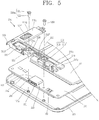
- FIG. 5 is an enlarged view of the antenna device 200 of the mobile terminal 100 of FIG. 4 and a coupling structure thereof
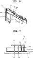
- FIG. 6 is a bottom perspective view of an antenna module 210 of FIG. 4
- FIG. 7 is a conceptual view of an electric connection path of the antenna device 200 of FIG. 4 .
- the antenna device 200 includes an antenna module 210 and at least one coupling member 220.
- the antenna module 210 may be mounted to and electrically coupled to the circuit board 181.
- the at least one coupling member 220 fixes the antenna module 210 to the terminal body.
- the antenna module 210 includes a carrier 211 and a radiator 212.
- the carrier 211 forms the appearance of the antenna module 210 and includes at least one surface on which the radiator 212 may be patterned or positioned.
- the carrier 211 may be formed of a synthetic resin and may be positioned proximate to the first end of the terminal body.
- the carrier 211 is depicted as being covered by the rear case 102.
- the carrier 211 may be covered by the battery cover 103 when mounted to the rear case 102 so as to be exposed to the outside when the battery cover is removed. In this manner, the carrier 211 is covered merely by the battery cover 103 so that transceiving performance of the antenna device 200 may be enhanced.
- the radiator 212 is positioned on at least one surface, such as a first surface 211e, of the carrier 211.
- the radiator 212 is formed of a conductive material in a preset pattern and is electrically coupled to the circuit board 181 so that transceived radio signals can be processed.
- the radiator 212 may extend to another surface, such as a third surface 211g, of the carrier 211.
- the third surface 211g of the carrier 211 faces the circuit board 181 and a grounding terminal 212a and a feeding terminal 212b are positioned on the third surface.
- the grounding terminal 212a and the feeding terminal 212b are electrically coupled to the circuit board 181.
- the radiator 212 may be configured to transceive radio signals of multiple bands.
- the radiator 212 may include a first radiating pattern 212' and a second radiating pattern 212" that diverge from each other on at least one point of the carrier 211.
- the first radiating pattern 212' and second radiating pattern 212" may be formed, for example, by printing conductive ink on at least one surface, such as the first surface 211e of the carrier 211, and then plating a metallic material on the conductive ink.
- the first radiating pattern 212' and second radiating pattern 212" may be formed by attaching a conductive pattern printed on a flexible printed circuit board (FPCB) onto the carrier 211.
- FPCB flexible printed circuit board
- the first radiating pattern 212' and second radiating pattern 212" may be configured to transceive radio signals of different frequency bands.
- the first radiating pattern 212' may be configured to transceive radio signals of a digital communications network (DCN) frequency band
- the second radiating pattern 212" may be configured to transceive radio signals of personal communication system (PCS), advanced wireless service (AWS).
- DCN digital communications network
- PCS personal communication system
- AWS advanced wireless service
- At least a portion of the second radiating pattern 212" may have a varying width to enable radio signals of different frequency bands to be transceived.
- the grounding terminal 212a extends from the first radiating pattern 212' and second radiating pattern 212" to ground the first radiating pattern 212' and second radiating pattern 212" to the circuit board 181.
- the feeding terminal 212b is electrically coupled to the circuit board 181 in a shape similar to a Planar Inverted-F Antenna (PIFA).
- a connection terminal 183 may be mounted to the circuit board 181 and be coupled to the grounding terminal 212a for a ground connection and the feeding terminal 212b for a feeding connection.
- All paths for electrically coupling the radiator 212 and the circuit board 181 to each other are coupled to a ground 185.
- the ground 185 may be formed at a specific layer of the circuit board 181, or may be an additional conductor positioned inside the terminal body.
- the first radiating pattern 212' and second radiating pattern 212" are coupled to the ground 185 of the circuit board 181 via the connection terminal 183 on the circuit board 181.
- the present invention is not so limited.
- the first radiating pattern 212' and second radiating pattern 212" may be directly coupled to an additional conductor positioned inside the terminal body. In this manner, the radiator 212 may be directly connected to the ground 185.
- the radiator 212 may transceive radio electromagnetic waves of a specific frequency band.
- the specific frequency band may correspond to PCS, AWS, DCN, long term evolution (LTE), and other technologies under development.
- the carrier 211 includes at least one opening 213 including a recess 214 in the first surface of the carrier.
- a thickness of the carrier is measured from the first surface 211e to a second surface 211f of the carrier opposite the first surface.
- the recess 214 has a depth less than the thickness of the carrier 211.
- the at least one opening 213 also includes an aperture 215 extending from a bottom surface 214a of the recess 214 to the second surface 211f of the carrier 211.
- Each coupling member 220 of the at least one coupling member 220 may be inserted into the aperture 215 of a corresponding opening of the at least one opening 213 to fix the carrier 211 to the terminal body.
- each of the at least one coupling member 220 includes a head 221 positioned in the recess 214 of a corresponding opening of the at least one opening 213, and a body 222 positioned in the aperture 215 of the corresponding opening of the at least one opening 213.
- the body 222 of each of the at least one coupling member 220 extends beyond the second surface 211f of the carrier 211 and couples to the terminal body.
- the at least one coupling member 220 may be a screw and the body 222 of the at least one coupling member 220 may have screw threads for coupling the body 222 to the body terminal.
- the at least one coupling member 220 is formed of a conductive material, and is disposed proximate to the radiator 212.
- the at least one coupling member 220 is spaced from the radiator a particular distance and is coupled to the radiator.
- the particular distance between the at least one coupling member 220 and the radiator 212 is 3.0 mm or less to enable coupling between the at least one coupling member 220 and the radiator 212.
- the at least one coupling member 220 may include a plurality of coupling members 220.
- the plurality of coupling members 220 may include a first screw 220a and a second screw 220b spaced apart from each other.
- the first screw 220a and second screw 220b may be positioned proximate to the first radiating pattern 212' and second radiating pattern 212".
- the first screw 220a and second screw 220b may be coupled to the first radiating pattern 212' and second radiating pattern 212".
- the head 221 of each of the at least one coupling member 220 may be coupled to the radiator 212.
- the head 221 of each of the at least one coupling member 220 is positioned in the recess 214 of a corresponding opening of the at least one opening 213 in the carrier 211 and positioned proximate to the radiator 212 at the particular distance.
- the radiator 212 may be formed to surround at least a portion of a perimeter of the recess 214 of an opening of the at least one opening 213 to enable the coupling between the head 221 of the at least one coupling member 220 and the radiator 212.
- the portion of the radiator 212 surrounding the at least a portion of the perimeter of the recess 214 may be formed in an arc shape, as depicted in FIG. 5 .
- the radiator 212 may extend along the first surface 211e of the carrier 211.
- a portion of the radiator 212 may also be bent to transition from the first surface 211e of the carrier 211 to a fourth surface 211h of the carrier and extend a preset length along the fourth surface 211 h to reduce a space occupied by the radiator 212 while enabling tranceiving of radio signals of a specific frequency band.
- the at least one coupling member 220 With the at least one coupling member 220 positioned in an opening of the at least one opening 213 and coupled to the terminal body, the at least one coupling member 220 is oriented in a direction crossing the radiator 212. Moreover, with the at least one coupling member 220 coupled with the radiator 212, the at least one coupling member 2 may be used to change a resonance frequency of the antenna module. The at least one coupling member 220 is also coupled to the radiator 212 for impedance matching in the form of a short diverged line. Furthermore, the at least one coupling member 220 may function as a type of stub.
- the at least one coupling member 220 is not electrically coupled to the circuit board 181.
- the head 221 of the at least one coupling member 220 may be electrically coupled to the radiator 212.
- the front case may be formed of a dielectric material. An end of the body 222 of the at least one coupling member 220, away from the head 221, may be coupled to an aperture 101 a in the front case 101 via a hole 181 a in the circuit board 181.
- the at least one coupling member 220 is positioned proximate to and spaced from the radiator 212 a particular distance and is coupled to the radiator 212.
- the at least one coupling member 220 may used as a resonance changing device to implement impedance matching. In this manner, the antenna may have tuned characteristics.
- the connector portion 230 and the antenna device 200 may be positioned proximate to the first end of the terminal body. Accordingly, the antenna characteristics may be influenced by the connector portion 230 when the connector portion 230 is formed of a metallic material.
- this embodiment of the present invention provides a structure for arranging the connector portion 230 and the antenna device 200 proximate to each other without degrading performance of the antenna device 200.
- the carrier 211 may be formed and positioned to cover the connector portion 230 to restrict movement of the connector portion 230. More particularly, the carrier 211 may include a recessed pressing portion 216 corresponding to the connector portion 230. In this manner, when the at least one coupling member 220 is coupled to the terminal body through the carrier 211 to fix the carrier 211 to the terminal body, the pressing portion 216 presses the connector portion 230 to restrict movement of the connector portion 230.
- the first screw 220a and second screw 220b may be positioned proximate to opposing sides of the connector portion 230, such as a first side 232 and a second side 233 of the connector portion 230.
- the first screw 220a and second screw 220b stably fix the carrier 211 to the terminal body.
- the pressing portion 216 presses the connector portion 230 to restrict movement of the connector portion 230.
- the antenna module 210 and the connector portion 230 may be positioned proximate to each other, which may minimize an area occupied by the antenna module 210 and the connector portion and prevent performance degradation of the antenna device 200. Additionally, since it is not necessary to space the antenna device 200 far from the connector portion 230, an area of a bezel portion 240 ( FIG. 2 ) of the mobile terminal 100 may be reduced.
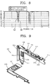
- FIG. 8 is a graph depicting performance characteristics of the antenna device 200 of FIG. 4 .
- the graph "1" (indicated by the thin solid line) represents a reflection coefficient of the radiator 212 when the at least one coupling member 220 is not provided.
- the graph "2" (indicated by the thick solid line) represents a reflection coefficient of the radiator 212 when the radiator 212 is coupled to the at least one coupling member 220.
- the radiator 212 resonates at different frequency bands (i.e., at a low frequency band and a high frequency band). As shown in the graph "2", when the radiator 212 is coupled to the at least one coupling member 220, antenna characteristics such as resonance frequency, bandwidth and gain change.
- the first screw 220 may be formed to resonate at a high frequency and the second screw 220b may be formed to resonate at a low frequency band. In this manner, if only the first screw 220a of the at least one coupling member 220 is coupled to the radiator 212, the antenna characteristics at a high frequency band change.
- FIG. 9 is a perspective view of the antenna module of FIG. 4 in a disassembled condition.
- the carrier 211 may include a first case 211 a and a second case 211b that form an outer appearance of the carrier 211.
- the speaker 152' for outputting sound may be positioned within an inner space 152c defined by the first case 211 a and the second case 211b.
- the speaker 152' may be electrically coupled to the circuit board 181 via a connection terminal 152b ( FIG. 6 ).
- the inner space 152c serves as a resonance sound chamber.
- An aperture 152a may be formed proximate to the speaker 152' so that sound can be directly output through the aperture.
- Another aperture may be formed in the carrier 211 at a preset distance from the speaker 152' to enhance performance of low sounds.
- the carrier 211 is divided into a first region 211c and a second region 211d.
- the radiator 212 is patterned on the first region 211c, and the speaker 152' is positioned in the second region 211d.
- the second region 211d is spaced from the first region.
- the first region 211c may extend laterally across the terminal body proximate the first end 106 of the terminal body, and the second region may extend longitudinally along a first side 107 of the terminal body and away from the first end 106 of the terminal body.
- the at least one coupling member 220 is positioned proximate to the radiator 212 at a particular distance for coupling the at least one coupling member to the radiator. Therefore, the at least one coupling member 220 may be used as a resonance changing device to implement impedance matching. In this manner, the antenna module 210 may have tuned characteristics.
- the antenna module 210 may be positioned to cover the connector portion 230 and the at least one coupling member 220 may be coupled to the terminal body through the carrier 211 to fix the antenna module 210 to the terminal body and allow the antenna module 210 to press against the connector portion 230 to restrict movement of the connector portion. In this manner, an area occupied by the antenna device 200 and connector portion 230 is minimized and degradation of performance of the antenna device is prevented. Furthermore, since there is no need to space the antenna device 200 away from the connector portion 230, an area of the bezel portion 240 can be reduced.
Landscapes
- Engineering & Computer Science (AREA)
- Computer Networks & Wireless Communication (AREA)
- Signal Processing (AREA)
- Telephone Set Structure (AREA)
Description
- The present invention relates to an antenna for transmitting and receiving radio signals. Although the present invention is suitable for a wide scope of applications, it is particularly suitable for implementation in a mobile terminal.
- Mobile terminals are presently configured to perform various functions. Such functions include data and voice communications, capturing still images and video via a camera, recording audio, playing music files and outputting music via a speaker system, and displaying images and video on a display. Some mobile terminals include additional functionality that supports game playing, while other mobile terminals are also configured as multimedia players. More recently, mobile terminals have been configured to receive broadcast and multicast signals that permit viewing of content, such as videos and television programs.
- Generally, terminals can be classified into mobile terminals and stationary terminals based on a presence or non-presence of mobility. Mobile terminals can also be classified into handheld terminals and vehicle mounted terminals based on whether they are configured to be carried by hand.
- There are ongoing efforts to support and increase the functionality of mobile terminals. Such efforts include software and hardware improvements, as well as changes and improvements in the structural components that form the mobile terminal. For example, a User interface (Ul) environment is provided in a mobile terminal to enable a user to easily and conveniently search for, or select, a desired function.
- Hardware improvements may include structural changes and improvements that allow a user to use a mobile terminal in a more convenient manner. For example, structural changes and improvements may be made to an antenna of the mobile terminal. The mobile terminal antennas transmit and receives electric waves for radio communication and should be designed to implement multiple bandwidths for satisfying various functions such as voice call, Wibro® and digital multimedia broadcasting (DMB). The antennas should also be miniaturized so as to be mounted in the mobile terminal and to reduce the amount of space occupied by the antennas. However, mobile terminal antennas have complicated structures and it is difficult to independently control parameter values that determine antenna characteristics such as resonance frequency, bandwidth and gain.
- Mobile terminals often include a connector portion for connection with a connector of an external device. The connector portion is often disposed at one end of a terminal body of the mobile terminal and is exposed to the outside. The antenna is also disposed at one end of the terminal body to aid in reducing Specific Absorption Rate (SAR). However, as the connector portion is often formed of a metallic material, the antenna characteristics may be influenced by the connector portion. Therefore, the antenna should be spaced from the connector portion in order to minimize the influence.
-
US2006/0089184 A1 discloses a built-in antenna module for a portable wireless terminal, comprising an antenna carrier to allow a distance between a radiator and a mainboard, the antenna carrier including a plate type junction panel to which the radiator is fixed, an outer barrier rib extending along an edge of the junction panel with a uniform height, and at least one compartment barrier rib for dividing a space formed by the junction panel and the outer barrier rib. - The problem is solved by the features of the independent claim.
- A mobile terminal of the present invention preferably includes a terminal body, an antenna module coupled to the terminal body, the antenna module including a radiator configured for transmitting and receiving radio signals, a circuit board electrically coupled to the antenna module and configured to process the transmitted and received radio signals, and at least one coupling member positioned proximate to and spaced from the radiator a particular distance. The at least one coupling member may be coupled to the radiator and configured for coupling the antenna module to the terminal body.
- In one aspect, the antenna module further includes a carrier positioned proximate to a first end of the terminal body and the radiator is positioned on at least a first surface of the carrier. In another aspect, the at least one coupling member extends through the carrier from the first surface to a second surface opposite the first surface. In a further aspect, the carrier defines at least one opening that includes a recess in the first surface having a depth less than a thickness of the carrier, the thickness of the carrier measured from the first surface to a second surface of the carrier opposite the first surface, and an aperture extending from a bottom surface of the recess to the second surface of the carrier, and each of the at least one coupling member includes a head portion positioned in the recess of a corresponding opening of the at least one opening, a bottom surface of the head portion configured to couple with the bottom surface of the recess, and a body portion positioned in the aperture of the corresponding opening; and the body portion of the at least one coupling member is configured to couple with the terminal body. In an additional aspect, at least a portion of the radiator surrounds at least a portion of a perimeter of the recess of an opening of the at least one opening. In another aspect, a connector portion positioned at the first end of the terminal body and electrically coupled to the circuit board, the connector portion including a terminal configured for electrically coupling with a connector of an external device, wherein the carrier is positioned to cover the connector portion such that the connector portion is positioned between the carrier and the terminal body, and the carrier applies pressure to the connector portion to restrict movement of the connector portion. In a further aspect, the at least one coupling member is configured to increase the pressure applied by the carrier to the connector portion when pressure applied by the bottom surface of the at least one coupling member against the bottom surface of the recess of the corresponding opening is increased. In an additional aspect, the at least one coupling member includes a first screw and a second screw, the first screw is positioned proximate a first side of the connector portion, and the second screw is positioned proximate a second side of the connector portion.
- In one aspect, at least a portion of the radiator includes a varying width for transmitting and receiving radio signals on different frequency bands. In another aspect, the at least one coupling member includes a first screw and a second screw, and the first screw and the second screw are spaced apart from each other. In a further aspect, the first screw is configured to resonate at a high frequency band of the different frequency bands, and the second screw is configured to resonate at a low frequency band of the different frequency bands.
- In one aspect, the terminal body includes a case formed of a dielectric material, the case forms an outer appearance of the terminal body, and the at least one coupling member is coupled to the case. In another aspect, the particular distance is 3.0 mm or less. In a further aspect, the at least one coupling member is coupled to the radiator and is further configured to change a resonance frequency of the antenna module. In an additional aspect, the radiator is further positioned in at least a portion of an opening of the at least one opening to surround at least a portion of a coupling member of the at least one coupling member. In another aspect, a transmission frequency of the radiator includes a frequency band corresponding to a personal communication system (PCS), an advanced wireless service (AWS), a digital communications network (DCN), or a long term evolution (LTE). In a further aspect, the mobile terminal further includes a speaker positioned within an inner space of the carrier, wherein the inner space of the carrier is configured to resonate sound output from the speaker. In an additional aspect, the carrier includes a first region including the first surface of the carrier, and a second region positioned spaced from the first region and including the inner space, wherein the radiator is patterned on the first surface of the carrier. In an additional aspect, the first region of the carrier extends in a lateral direction of the terminal body proximate the first end of the terminal body, the second region of the carrier extends along a first side of the terminal body and away from the first end of the terminal body.
- The accompanying drawings, which are included to provide a further understanding of the invention and are incorporated in and constitute a part of this specification, illustrate exemplary embodiments and together with the description serve to explain the principles of the invention.
- In the drawings:
-
FIG. 1 is a block diagram of a mobile terminal according to an embodiment of the present disclosure. -
FIG. 2 is a front perspective view of a mobile terminal according to an embodiment of the invention. -
FIG. 3 is a rear perspective view of the mobile terminal ofFIG. 2 . -
FIG. 4 is a perspective view of the mobile terminal ofFIG. 3 in a disassembled condition and including an antenna device. -
FIG. 5 is an enlarged view of an antenna device of the mobile terminal ofFIG. 4 and a coupling structure of the antenna. -
FIG. 6 is a bottom perspective view of an antenna module of the mobile terminal ofFIG. 4 . -
FIG. 7 is a conceptual view of an electric connection path of an antenna device of the mobile terminal ofFIG. 4 . -
FIG. 8 is a graph depicting performance of the antenna device ofFIG. 4 . -
FIG. 9 is a perspective view of the antenna module ofFIG. 4 in a disassembled condition. - In the following detailed description, reference is made to the accompanying drawing figures which form a part hereof, and which show by way of illustration specific embodiments of the invention. It is to be understood by those of ordinary skill in this technological field that other embodiments may be utilized, and structural, electrical, as well as procedural changes may be made without departing from the scope of the present invention. Wherever possible, the same reference numbers will be used throughout the drawings to refer to the same or similar parts.
- As used herein, the suffixes "module" and "unit" are used for facilitation of the detailed description of the present invention and do not have meanings or functions different from each other. Therefore, significant meanings or roles are not given to the suffixes themselves and it is understood that the terms 'module' and 'unit' can be used together or interchangeably.
- The present invention can be applicable to various types of terminals. Examples of such terminals include mobile as well as stationary terminals, such as mobile phones, user equipment, smart phones, DTV, computers, digital broadcast terminals, personal digital assistants, portable multimedia players (PMP), E-books, and navigation systems.
- However, by way of non-limiting example only, further description will be provided with regard to a
mobile terminal 100. It should be noted that such teachings may apply equally to other types of terminals. -
FIG. 1 is a block diagram of amobile terminal 100 in accordance with an embodiment of the present invention. Referring toFIG. 1 , themobile terminal 100 includes awireless communication unit 110, an audio/video (AN)input unit 120, auser input unit 130, asensing unit 140, anoutput unit 150, amemory 160, aninterface unit 170, acontroller 180, and apower supply unit 190. AlthoughFIG. 1 shows themobile terminal 100 having various components, it is understood that implementing all of the illustrated components is not a requirement. More or fewer components may alternatively be implemented. - The
wireless communication unit 110 includes one or more components that permit wireless communication between themobile terminal 100 and a wireless communication system or a network within which themobile terminal 100 is located. For example, thewireless communication unit 110 includes abroadcast receiving module 111, amobile communication module 112, awireless Internet module 113, a short-range communication module 114 and alocation information module 115. For non-mobile terminals, thewireless communication unit 110 may be replaced with a wired communication unit. Thewireless communication unit 110 and a wired communication unit (not shown) may be commonly referred to as a communication unit. - The
broadcast receiving module 111 receives a broadcast signal and/or broadcast associated information from an external broadcast managing entity via a broadcast channel. The broadcast channel may include a satellite channel and/or a terrestrial channel. - The broadcast managing entity may refer to a system that transmits a broadcast signal and/or broadcast associated information. The broadcast managing entity may be a server that generates and transmits broadcast signals and/or broadcast associated information or a server for receiving previously generated broadcast signals and/or broadcast-related information and transmitting the broadcast signals and/or the broadcast associated information to the
mobile terminal 100. The broadcast signals may include not only TV broadcast signals, radio broadcast signals, and data broadcast signals, but also signals in the form of a TV broadcast signal combined with a radio broadcast signal. - The broadcast associated information may be information about a broadcast channel, a broadcast program, or a broadcast service provider. The broadcast associated information may even be provided over a mobile communication network, in which case the broadcast associated information may be received via the
mobile communication module 112. Examples of broadcast associated information include an electronic program guide (EPG) of digital multimedia broadcasting (DMB) and an electronic service guide (ESG) of digital video broadcast-handheld (DVB-H). - The
broadcast receiving module 111 may receive broadcast signals transmitted from various types of broadcast systems. As a non-limiting example, the broadcast systems include digital multimedia broadcasting-terrestrial (DMB-T), digital multimedia broadcasting-satellite (DMB-S), digital video broadcast-handheld (DVB-H), a data broadcasting system known as media forward link only (MediaFLO®) and integrated services digital broadcast-terrestrial (ISDB-T). Thebroadcast receiving module 111 may also receive multicast signals. The broadcast signals and/or the broadcast associated information received by thebroadcast receiving module 111 may be stored in a suitable storage device, such as in thememory 160. - The
mobile communication module 112 transmits/receives wireless signals to/from at least one of a base station, an external terminal or a server over a mobile communication network. The wireless signals may represent, for example, voice call signals, video telephony call signals or data in various forms according to the transmission/reception of text and/or multimedia messages. - The
wireless Internet module 113 supports Internet access for themobile terminal 100. Thewireless Internet module 113 may be internally or externally coupled to themobile terminal 100. Suitable technologies for wireless Internet include, but are not limited to, WLAN (Wireless LAN), Wi-Fi®, Wibro® (Wireless broadband), Wimax® (World Interoperability for Microwave Access), and HSDPA (High Speed Downlink Packet Access). - The
wireless Internet module 113 may be replaced with a wired Internet module (not shown) in non-mobile terminals. Thewireless Internet module 113 and the wired Internet module may be commonly referred to as an Internet module. Moreover, as mentioned in the foregoing description, thewireless Internet module 113 can receive or download the data relevant to the area in which themobile terminal 100 is located from the external server. - The short-
range communication module 114 facilitates relatively short-range communications. Suitable technologies for short-range communication include, but are not limited to, radio frequency identification (RFID), infrared data association (IrDA), ultra-wideband (UWB), as well as networking technologies such as Bluetooth® and ZigBee®. - The
location information module 115 identifies or otherwise obtains a location of themobile terminal 100. Thelocation information module 115 may obtain position information by using a global navigation satellite system (GNSS). The GNSS is a term used to describe radio navigation satellite systems configured to send reference signals capable of determining their positions on the surface of the earth or near the surface of the earth while revolving around the earth. The GNSS includes: a global position system (GPS) operated by the U.S.A.; Galileo operated by Europe; a global orbiting navigational satellite system (GLONASS) operated by Russia; Compass operated by China; and a quasi-zenith satellite system (QZSS) operated by Japan. - As a typical example of the GNSS, the
location information module 115 is a GPS module. Thelocation information module 115 may calculate information related to distances between one point or object and at least three satellites and information related to the time when the distance information was measured and apply trigonometry to the obtained distance information to obtain three-dimensional position information on the point or object according to the latitude, longitude, and altitude at a predetermined time. Furthermore, a method of calculating position and time information using three satellites and correcting the calculated position and time information using another satellite may also used. Thelocation information module 115 continues to calculate a current position in real time and to calculate velocity information based on the position information. - With continued reference to
FIG. 1 , the audio/video (A/V)input unit 120 may be configured to provide audio or video signal input to themobile terminal 100. The A/V input unit 120 may include acamera 121 and amicrophone 122. Thecamera 121 processes image frames of still pictures or video obtained by an image sensor in a photographing mode or a video telephony mode. The processed image frames may be displayed on adisplay unit 151. - The image frames processed by the
camera 121 may be stored in thememory 160 or transmitted to an external device through thewireless communication unit 110. Optionally, themobile terminal 100 can include two ormore cameras 121, if appropriate. - The
microphone 122 receives an external audio signal while themobile terminal 100 is in a particular mode, such as a phone call mode, a recording mode and/or a voice recognition mode. The received audio signal is processed and converted into digital data. In the call mode, the processed digital data is transformed into a format transmittable to a mobile communication base station via themobile communication module 112 and then output. Furthermore, themobile terminal 100, and in particular the A/V input unit 120, may include a noise removing algorithm to remove noise generated during the course of receiving the external audio signal. - The
user input unit 130 generates input data in response to user manipulation of an associated input device or devices. Examples of such devices include a keypad, a dome switch, a static pressure/capacitance touchpad, a jog wheel and a jog switch. A specific example of theuser input unit 130 is a touch screen in which a touchpad is combined with a display, as will be described below. - The
sensing unit 140 provides status measurements of various aspects of themobile terminal 100. For example, thesensing unit 140 may detect an open/closed status of themobile terminal 100, relative positioning of components, such as a display and a keypad of themobile terminal 100, a change of position of themobile terminal 100 or a component of themobile terminal 100, a presence or absence of user contact with themobile terminal 100, an orientation of themobile terminal 100 and/or acceleration/deceleration of themobile terminal 100. - As an example, the
mobile terminal 100 may be configured as a slide-type mobile terminal in which thesensing unit 140 may sense whether a sliding portion of themobile terminal 100 is open or closed. Thesensing unit 140 may also sense a presence or absence of power provided by thepower supply unit 190 or a presence or absence of a coupling or other connection between theinterface unit 170 and an external device. Thesensing unit 140 may include aproximity sensor 141. - The
output unit 150 generates output relevant to the senses of sight, hearing and touch. Theoutput unit 150 may include adisplay unit 151, anaudio output module 152, analarm unit 153, and ahaptic module 154. - The
display unit 151 displays information processed by themobile terminal 100. For example, when themobile terminal 100 is in a call mode, thedisplay unit 151 may display a user interface (UI) or a graphic user interface (GUI) associated with the call. If themobile terminal 100 is in a video communication mode or a photograph mode, thedisplay unit 151 may display a photographed and/or received picture, a UI or a GUI. - The
display unit 151 may include a liquid crystal display (LCD), a thin film transistor liquid crystal display (TFT LCD), an organic light-emitting diode (OLED), a flexible display, or a 3-dimensional display. Themobile terminal 100 may include one or more of such displays. - The
display unit 151 may have a transparent or light-transmittive type configuration, hereinafter referred to as a transparent display. A transparent OLED (TOLED) is an example of a transparent display. A rear configuration of thedisplay unit 151 may also have the light-transmittive type configuration. In this configuration, a user is able to see an object located behind the terminal body via the area occupied by thedisplay unit 151 of the terminal body. - At least two
display units 151 may be provided. For example, a plurality ofdisplay units 151 may be provided on a single face of themobile terminal 100 spaced apart from each other or built in one body. Alternatively, each of a plurality ofdisplay units 151 may be provided on different faces of themobile terminal 100. - If the
display unit 151 and a sensor for detecting a touch action (hereafter referred to as a 'touch sensor') are constructed in a mutual-layered structure (hereafter referred to as a 'touch screen'), thedisplay unit 151 may be used as an input device and an output device. For example, the touch sensor may include a touch film, a touch sheet or a touchpad. - The touch sensor can be configured to convert a pressure applied to a specific portion of the
display unit 151 or a variation of electrostatic capacity generated from a specific portion of thedisplay unit 151 to an electric input signal. The touch sensor may detect a pressure of a touch as well as a touched position or magnitude of the touch. - If a touch input is made to the touch sensor, a signal(s) corresponding to the touch input is transferred to a touch controller (not shown). The touch controller processes the signal(s) and then transfers corresponding data to the
controller 180. Thecontroller 180 may determine which portion of thedisplay unit 151 is touched. - With continued reference to
FIG. 1 , aproximity sensor 141 can be provided within themobile terminal 100 enclosed by the touch screen or around the touch screen. Theproximity sensor 141 may detect a presence or non-presence of an object approaching a specific detecting surface or an object existing around theproximity sensor 141 using an electromagnetic field strength or infrared ray without mechanical contact. Accordingly, theproximity sensor 141 may have greater durability and greater utility than a contact type sensor. - The
proximity sensor 141 can include a transmittive photoelectric sensor, a direct reflective photoelectric sensor, a mirror reflective photoelectric sensor, a radio frequency oscillation proximity sensor, an electrostatic capacity proximity sensor, a magnetic proximity sensor or an infrared proximity sensor. If the touch screen is an electrostatic type touch screen, theproximity sensor 141 may detect proximity of a pointer using a variation of an electric field according to the proximity of the pointer and the touch screen or touch sensor may be classified as theproximity sensor 141. - An action in which a pointer approaches the touch screen without contacting the touch screen, yet is recognized as being located on the touch screen, is referred to as a 'proximity touch'. An action in which the pointer actually touches the touch screen is referred to as a 'contact touch'. The position on the touch screen proximity-touched by the pointer refers to the position of the pointer that vertically opposes the touch screen when the pointer performs the proximity touch.
- The
proximity sensor 141 may detect a proximity touch and/or a proximity touch pattern, such as proximity touch distance, proximity touch duration, proximity touch position or proximity touch shift state. Information corresponding to the detected proximity touch action and/or the detected proximity touch pattern may be displayed on the touch screen. - The
audio output module 152 may output audio data that is received from thewireless communication unit 110 in, for example, a call-receiving mode, a call-placing mode, a recording mode, a voice recognition mode or a broadcast receiving mode. Theaudio output module 152 may output audio data stored in thememory 160. Theaudio output module 152 may output an audio signal relevant to a function, such as a call signal receiving sound, or a message receiving sound performed by themobile terminal 100. Theaudio output module 152 may include, for example, a receiver, a speaker or a buzzer. - The
alarm unit 153 outputs a signal for announcing an occurrence of a particular event associated with themobile terminal 100. Typical events include a call signal reception, a message reception, a key signal input and a touch input. Thealarm unit 153 may output a signal for announcing the event occurrence via vibration as well as a video signal or an audio signal. The video signal is output via thedisplay unit 151 and the audio signal is output via theaudio output module 152. Therefore, at least thedisplay unit 151 or theaudio output module 152 can be regarded as part of thealarm unit 153. - The
haptic module 154 may generate various haptic effects that can be sensed by a user. Vibration is a representative tactile effect generated by thehaptic module 154. Strength and pattern of the vibration generated from thehaptic module 154 may be controllable. For example, vibrations differing from each other can be output by being synthesized together or can be output in sequence. - The
haptic module 154 may generate various haptic effects in addition to vibration. For example, thehaptic module 154 may generate an effect caused by a pin array vertically moving against skin being touched, an air injection force via an injection hole, an air suction force via a suction hole, an effect of skimming on a skin surface, an effect of contact with an electrode, an effect of electrostatic power and/or an effect of a hot/cold sense using an endothermic or exothermic device. - The
haptic module 154 can be configured to provide the haptic effect via direct contact. Thehaptic module 154 can also be configured to enable a user to experience the haptic effect via muscular sense of a finger or an arm. Two or morehaptic modules 154 can be provided according to a configuration of themobile terminal 100. - The
memory 160 is generally used to store various types of data for supporting the processing, control, and storage requirements of themobile terminal 100. Examples of such data include program instructions for applications operating on themobile terminal 100, contact data, phonebook data, messages, audio, still pictures, and moving pictures. A recent use history or a cumulative use frequency of each data, such as use frequency for each phonebook, each message or each multimedia, may be stored in thememory 160. Moreover, data for various patterns of vibration and/or sound to be output when a touch input is received at the touch screen may be stored in thememory 160. - The
memory 160 may include, for example, a flash memory, a hard disk, a multimedia card micro type memory, a random access memory (RAM), a static random access memory (SRAM), a read-only memory (ROM), an electrically erasable programmable read-only memory (EEPROM), a programmable read-only memory (PROM), a magnetic memory, a magnetic disk an optical disk, or a card type memory, such as SD memory or XD memory. Themobile terminal 100 may operate in association with a web storage that performs a storage function of thememory 160 via the Internet. - The
interface unit 170 couples themobile terminal 100 with external devices. Theinterface unit 170 receives data from an external device. Theinterface unit 170 is supplied with power and may be configured to deliver the power to elements within themobile terminal 100. - The
interface unit 170 may be configured to enable data to be transferred from themobile terminal 100 to an external device. Theinterface unit 170 may be configured to include a wired/wireless headset port, an external charger port, a wire/wireless data port, a memory card port, a port for coupling to a device having an identity module, an audio input/output (I/O) port, a video input/output (I/O) port or an earphone port. - The identity module is a chip or card that stores various types of information for authenticating a use authority of the
mobile terminal 100 and can include a user identity module (UIM), a subscriber identity module (SIM) and/or a universal subscriber identity module (USIM). A device provided with the above identity module (hereafter referred to as an 'identity device') may be manufactured in the form of a smart card. The identity device is connectable to themobile terminal 100 via a corresponding port. - The
interface unit 170 may be configured as a passage for supplying power to the mobile terminal 100 from a cradle that is connected to themobile terminal 100. Theinterface unit 170 may facilitate delivery of various command signals, which are input via the cradle by a user, to themobile terminal 100. Various command signals input via the cradle or the power may provide an indication for recognizing that themobile terminal 100 is correctly loaded in the cradle. - The
controller 180 typically controls the overall operations of themobile terminal 100. For example, thecontroller 180 performs control and processing associated with voice calls, data communications and video conferences. Thecontroller 180 may include amultimedia module 184 that provides multimedia playback. Themultimedia module 184 may be configured as part of thecontroller 180 or may be configured as a separate component. Thecontroller 180 may also perform pattern recognition processing for recognizing a handwriting input performed on the touch screen as a character and/or recognizing a picture drawing input performed on the touch screen as characters or images. - The
power supply unit 190 provides power required by the various components of themobile terminal 100. The power may be internal power, external power, or combinations thereof. - Embodiments of the present invention described in the following description may be implemented within a recording medium that can be read by a computer or a computer-like device using software, hardware or combinations thereof. For hardware implementations, arrangements and embodiments may be implemented using at least one of application specific integrated circuits (ASICs), digital signal processors (DSPs), digital signal processing devices (DSPDs), programmable logic devices (PLDs), field programmable gate arrays (FPGAs), processors, controllers, microcontrollers, microprocessors or electrical units for performing other functions. Such embodiments may also be implemented by the
controller 180. - For a software implementation, arrangements and embodiments described herein may be implemented with separate software modules, such as procedures and functions, each of which may perform one or more of the functions and operations described herein. Software codes may be implemented with a software application written in any suitable programming language and may be stored in the
memory 160 and executed by thecontroller 180. -
FIG. 2 is a front perspective view showing an example of a front of themobile terminal 100. Themobile terminal 100 ofFIG. 2 is depicted as a bar-type terminal body. However, themobile terminal 100 may be implemented in a variety of different configurations. - Examples of such configurations include a folder-type, a slide-type, a rotational-type, a swing-type and combinations thereof. For clarity, further disclosure will primarily relate to a bar-type
mobile terminal 100. However such teachings apply equally to other types of mobile terminals. - The
mobile terminal 100 includes a case, such as a casing, housing, or cover, that forms an exterior of the mobile terminal. The case may be divided into afront case 101 and arear case 102. Various electric/electronic parts are provided in a space between thefront case 101 and therear case 102. A middle case may be further provided between thefront case 101 and therear case 102. The cases can be formed by injection molding of synthetic resin or may be formed of a metallic material, such as stainless steel (STS), aluminum (Al) or titanium (Ti). - The
display unit 151,audio output module 152,camera 121, first and seconduser manipulating units microphone 122 and/or theinterface unit 170 can be provided on the terminal body, and more particularly on thefront case 101. - The
display unit 151 occupies most of a main face of thefront case 101. Theaudio output module 152 and thecamera 121 may be provided at an area adjacent to one end portion of thedisplay unit 151, while the first manipulatingunit 130a and themicrophone 122 may be provided at an area adjacent to the other, opposite end portion of thedisplay unit 151. The second manipulatingunit 130b and theinterface unit 170 can be provided on lateral sides of the front andrear cases - The user input unit 130 (see
FIG. 1 ) may receive a command for controlling an operation of themobile terminal 100. Theuser input unit 130 may include a plurality of manipulating units, such as the first and second manipulatingunits user manipulating units - Content input via the first manipulating
unit 130a or the second manipulatingunit 130b can be set to be different. For example, commands such as start, end and scroll can be input via the first manipulatingunit 130a. Commands for adjusting volume of sound output from theaudio output module 152 and for switching thedisplay unit 151 to a touch recognizing mode can be input via the second manipulatingunit 130b. Many other such configurations may be contemplated. -
FIG. 3 is a rear perspective diagram of themobile terminal 100 shown inFIG. 2 . Other embodiments, configurations and arrangements may also be provided. - As shown in
FIG. 3 , an additional camera 121' can be provided on a rear side of the terminal body, and more particularly, on therear case 102. The camera 121' on therear case 102 has a photographing direction that is substantially opposite to that of thecamera 121 shown inFIG. 2 and may have a different resolution. - For example, the
camera 121 may use a smaller number of pixels than the camera 121', and thereby have a relatively lower resolution, to capture and transmit an image of the user's face for a video call. On the other hand, the camera 121' may use a greater number of pixels than thecamera 121, and thereby have a relatively greater resolution in general, for capturing an image of a general subject for photography without transmitting the captured image. Thecameras 121 and 121' may be capable of being rotated in relation to the terminal body or to pop-up from the terminal body. - A
flash 123 and amirror 124 may be disposed adjacent to the camera 121'. Theflash 123 projects light toward a subject when photographing the subject using the camera 121'. When a user attempts to take a picture of himself/herself (self-photography) using the camera 121', themirror 124 enables the user to view his/her face reflected by themirror 124. - An additional audio output module 152' can be disposed at the rear side of the terminal body. The additional audio output module 152' facilitates a stereo function in conjunction with the
audio output module 152 illustrated inFIG. 2 and may be used for implementation of a speakerphone mode when communicating via themobile terminal 100. - The
power supply unit 190 for supplying power to themobile terminal 100 may be provided in the terminal body. Thepower supply unit 190 can be configured to be built within the terminal body or to be detachably connected to the terminal body. - Referring to
FIGS. 2-4 , the terminal body includes aconnector portion 230 positioned at one end, such as afirst end 106, of the terminal body. Theconnector portion 230 is an example of theinterface unit 170 which connects themobile terminal 100 to an external device. For example, theconnector portion 230 may be a data port for transmitting and receiving data to/from an external device, or a power port for receiving power from the outside. - Antennas may be disposed in the terminal body. For example, the
mobile terminal 100 may include an antenna for mobile communication and an antenna for receiving broadcasting signals or wireless Internet signals. The antennas may be combined together to integrally provide various wireless communication services. -
FIG. 4 is a disassembled perspective view of themobile terminal 100 ofFIG. 3 . Referring toFIG. 4 , acircuit board 181 is positioned within the terminal body. Thecircuit board 181 may be mounted to thefront case 101 or therear case 102, or to an additional inner structure. InFIG. 4 , thecircuit board 181 is depicted as covered by an inner surface of therear case 102. - Various electronic devices may be mounted on a surface of the
circuit board 181. Thecircuit board 181 may also include ashield member 182 for protecting the electronic devices mounted on thecircuit board 181. As an example, theshield member 182 may be a metallic plate. - The
circuit board 181 is an example of the controller 180 (FIG. 1 ) for operating various components of themobile terminal 100. The mobile terminal may include a plurality ofcircuit boards 181 and the combination of the plurality of circuit boards may function as thecontroller 180. Thecircuit board 181 is electrically coupled to anantenna device 200 and processes a radio signal corresponding to a radio electromagnetic wave transceived by theantenna device 200. - The
rear case 102 may include a recessedaccommodation portion 192 for accommodating abattery 191. Theaccommodation portion 192 may include an open bottom surface through which theshield member 182 is exposed to the outside of themobile terminal 100 when thebattery 191 is removed. In this manner, theshield member 182 forms the bottom of theaccommodation portion 192. Thebattery 191 and theaccommodation portion 192 are an example of the power supply unit 190 (FIG. 1 ). - A
battery cover 103 for covering thebattery 191 and theaccommodation portion 192 may be detachably mounted to therear case 102. Thebattery cover 103 is an example of the case that forms the outer appearance of the terminal body and may cover the entirerear surface 108 of the mobile terminal. - When the
connector portion 230 is positioned at thefirst end 106 of the terminal body, the connector portion may be positioned proximate to themicrophone 122. Themobile terminal 100 may be coupled to external devices, such as a computer, a printer, a multimedia device, or a memory device via a data cable coupled to theconnector portion 230. Alternatively, theconnector portion 230 may be implemented as a power port coupled to a connector or a cradle or a docking station to enable themobile terminal 100 to receive power. On the other hand, the connector portion may be coupled to an external speaker. - The
connector portion 230 includes a terminal 231 that may be connected to a connector of the external device. As an example, theconnector portion 230 may be a Universal Serial Bus (USB) port. - The
connector portion 230 is electrically coupled to thecircuit board 181. For example, theconnector portion 230 may be mounted onto thecircuit board 181 via a Surface Mount Technology (SMT) process. Lead or one of other materials commonly known in the art for use in the SMT process is patterned on thecircuit board 181, and theconnector portion 230 is positioned on the lead or other material using mounting equipment. Thereafter, theconnector portion 230 passes through a reflow oven in which the lead or other material is melted to solder the connector portion to thecircuit board 181. The patterned lead or other material may form a coupling layer between theconnector portion 230 and thecircuit board 181. The coupling layer is formed as the patterned lead or other material is melted in the reflow oven and subsequently solidified upon cooling. - The
antenna device 200 transceives radio signals. To reduce Specific Absorption Rate (SAR), theantenna device 200 may be positioned toward the first 106 (FIG. 4 ) end of the terminal body proximate to themicrophone 122. In this manner, theantenna device 200 is positioned away from the audio output module 152 (FIG. 2 ). Theantenna device 200 may be configured to transceive radio signals of multiple bands. The mobile terminal may include a plurality of antenna devices, each performing a different function. To minimize interference between the plurality ofantenna devices 200, the antenna devices may be spaced apart from each other a set distance. - When both the
connector portion 230 and theantenna device 200 are positioned toward thefirst end 106 of the terminal body, antenna characteristics such as a resonance frequency, bandwidth and gain may be influenced by theconnector portion 230 when the connector portion includes a metallic material. Asmobile terminals 100 tend to be relatively small, it is an object of the present invention to include a structure for tuning theantenna device 200 such that positioning the antenna device proximate to theconnector portion 230 does not degrade performance of the antenna device. Hereinafter, theantenna device 200 and the structure will be explained in more detail with reference to the attached drawings. -
FIG. 5 is an enlarged view of theantenna device 200 of themobile terminal 100 ofFIG. 4 and a coupling structure thereof,FIG. 6 is a bottom perspective view of anantenna module 210 ofFIG. 4 , andFIG. 7 is a conceptual view of an electric connection path of theantenna device 200 ofFIG. 4 . Referring toFIGS. 5 to 7 , theantenna device 200 includes anantenna module 210 and at least onecoupling member 220. Theantenna module 210 may be mounted to and electrically coupled to thecircuit board 181. The at least onecoupling member 220 fixes theantenna module 210 to the terminal body. - The
antenna module 210 includes acarrier 211 and aradiator 212. Thecarrier 211 forms the appearance of theantenna module 210 and includes at least one surface on which theradiator 212 may be patterned or positioned. Thecarrier 211 may be formed of a synthetic resin and may be positioned proximate to the first end of the terminal body. - In
FIG. 4 , thecarrier 211 is depicted as being covered by therear case 102. However, thecarrier 211 may be covered by thebattery cover 103 when mounted to therear case 102 so as to be exposed to the outside when the battery cover is removed. In this manner, thecarrier 211 is covered merely by thebattery cover 103 so that transceiving performance of theantenna device 200 may be enhanced. - The
radiator 212 is positioned on at least one surface, such as afirst surface 211e, of thecarrier 211. Theradiator 212 is formed of a conductive material in a preset pattern and is electrically coupled to thecircuit board 181 so that transceived radio signals can be processed. - The
radiator 212 may extend to another surface, such as athird surface 211g, of thecarrier 211. Thethird surface 211g of thecarrier 211 faces thecircuit board 181 and agrounding terminal 212a and afeeding terminal 212b are positioned on the third surface. Thegrounding terminal 212a and the feedingterminal 212b are electrically coupled to thecircuit board 181. - The
radiator 212 may be configured to transceive radio signals of multiple bands. For example, referring toFIG. 5 theradiator 212 may include a first radiating pattern 212' and asecond radiating pattern 212" that diverge from each other on at least one point of thecarrier 211. The first radiating pattern 212' andsecond radiating pattern 212" may be formed, for example, by printing conductive ink on at least one surface, such as thefirst surface 211e of thecarrier 211, and then plating a metallic material on the conductive ink. Alternatively, the first radiating pattern 212' andsecond radiating pattern 212" may be formed by attaching a conductive pattern printed on a flexible printed circuit board (FPCB) onto thecarrier 211. - The first radiating pattern 212' and
second radiating pattern 212" may be configured to transceive radio signals of different frequency bands. For example, the first radiating pattern 212' may be configured to transceive radio signals of a digital communications network (DCN) frequency band, while thesecond radiating pattern 212" may be configured to transceive radio signals of personal communication system (PCS), advanced wireless service (AWS). At least a portion of thesecond radiating pattern 212" may have a varying width to enable radio signals of different frequency bands to be transceived. - Referring to
FIG. 7 , thegrounding terminal 212a extends from the first radiating pattern 212' andsecond radiating pattern 212" to ground the first radiating pattern 212' andsecond radiating pattern 212" to thecircuit board 181. The feeding terminal 212b is electrically coupled to thecircuit board 181 in a shape similar to a Planar Inverted-F Antenna (PIFA). Aconnection terminal 183 may be mounted to thecircuit board 181 and be coupled to thegrounding terminal 212a for a ground connection and the feeding terminal 212b for a feeding connection. - All paths for electrically coupling the
radiator 212 and thecircuit board 181 to each other are coupled to aground 185. Theground 185 may be formed at a specific layer of thecircuit board 181, or may be an additional conductor positioned inside the terminal body. In this manner, the first radiating pattern 212' andsecond radiating pattern 212" are coupled to theground 185 of thecircuit board 181 via theconnection terminal 183 on thecircuit board 181. However, the present invention is not so limited. For example, the first radiating pattern 212' andsecond radiating pattern 212" may be directly coupled to an additional conductor positioned inside the terminal body. In this manner, theradiator 212 may be directly connected to theground 185. - The
radiator 212 may transceive radio electromagnetic waves of a specific frequency band. The specific frequency band may correspond to PCS, AWS, DCN, long term evolution (LTE), and other technologies under development. - As shown in
FIG. 5 , thecarrier 211 includes at least oneopening 213 including arecess 214 in the first surface of the carrier. A thickness of the carrier is measured from thefirst surface 211e to a second surface 211f of the carrier opposite the first surface. Therecess 214 has a depth less than the thickness of thecarrier 211. The at least oneopening 213 also includes anaperture 215 extending from abottom surface 214a of therecess 214 to the second surface 211f of thecarrier 211. Eachcoupling member 220 of the at least onecoupling member 220 may be inserted into theaperture 215 of a corresponding opening of the at least oneopening 213 to fix thecarrier 211 to the terminal body. - More particularly, each of the at least one
coupling member 220 includes ahead 221 positioned in therecess 214 of a corresponding opening of the at least oneopening 213, and abody 222 positioned in theaperture 215 of the corresponding opening of the at least oneopening 213. Moreover, thebody 222 of each of the at least onecoupling member 220 extends beyond the second surface 211f of thecarrier 211 and couples to the terminal body. The at least onecoupling member 220 may be a screw and thebody 222 of the at least onecoupling member 220 may have screw threads for coupling thebody 222 to the body terminal. - The at least one
coupling member 220 is formed of a conductive material, and is disposed proximate to theradiator 212. The at least onecoupling member 220 is spaced from the radiator a particular distance and is coupled to the radiator. The particular distance between the at least onecoupling member 220 and theradiator 212 is 3.0 mm or less to enable coupling between the at least onecoupling member 220 and theradiator 212. - The at least one
coupling member 220 may include a plurality ofcoupling members 220. For example, the plurality ofcoupling members 220 may include afirst screw 220a and asecond screw 220b spaced apart from each other. Thefirst screw 220a andsecond screw 220b may be positioned proximate to the first radiating pattern 212' andsecond radiating pattern 212". Moreover, thefirst screw 220a andsecond screw 220b may be coupled to the first radiating pattern 212' andsecond radiating pattern 212". - The
head 221 of each of the at least onecoupling member 220 may be coupled to theradiator 212. Thehead 221 of each of the at least onecoupling member 220 is positioned in therecess 214 of a corresponding opening of the at least oneopening 213 in thecarrier 211 and positioned proximate to theradiator 212 at the particular distance. Theradiator 212 may be formed to surround at least a portion of a perimeter of therecess 214 of an opening of the at least oneopening 213 to enable the coupling between thehead 221 of the at least onecoupling member 220 and theradiator 212. The portion of theradiator 212 surrounding the at least a portion of the perimeter of therecess 214 may be formed in an arc shape, as depicted inFIG. 5 . - As depicted in
FIGS. 5 and6 , theradiator 212 may extend along thefirst surface 211e of thecarrier 211. A portion of theradiator 212 may also be bent to transition from thefirst surface 211e of thecarrier 211 to afourth surface 211h of the carrier and extend a preset length along thefourth surface 211 h to reduce a space occupied by theradiator 212 while enabling tranceiving of radio signals of a specific frequency band. - With the at least one
coupling member 220 positioned in an opening of the at least oneopening 213 and coupled to the terminal body, the at least onecoupling member 220 is oriented in a direction crossing theradiator 212. Moreover, with the at least onecoupling member 220 coupled with theradiator 212, the at least onecoupling member 2 may be used to change a resonance frequency of the antenna module. The at least onecoupling member 220 is also coupled to theradiator 212 for impedance matching in the form of a short diverged line. Furthermore, the at least onecoupling member 220 may function as a type of stub. - The at least one
coupling member 220 is not electrically coupled to thecircuit board 181. However, thehead 221 of the at least onecoupling member 220 may be electrically coupled to theradiator 212. The front case may be formed of a dielectric material. An end of thebody 222 of the at least onecoupling member 220, away from thehead 221, may be coupled to anaperture 101 a in thefront case 101 via ahole 181 a in thecircuit board 181. - As explained previously, the at least one
coupling member 220 is positioned proximate to and spaced from theradiator 212 a particular distance and is coupled to theradiator 212. As a result, the at least onecoupling member 220 may used as a resonance changing device to implement impedance matching. In this manner, the antenna may have tuned characteristics. - As previously explained, the
connector portion 230 and theantenna device 200 may be positioned proximate to the first end of the terminal body. Accordingly, the antenna characteristics may be influenced by theconnector portion 230 when theconnector portion 230 is formed of a metallic material. As will be explained, this embodiment of the present invention provides a structure for arranging theconnector portion 230 and theantenna device 200 proximate to each other without degrading performance of theantenna device 200. - The
carrier 211 may be formed and positioned to cover theconnector portion 230 to restrict movement of theconnector portion 230. More particularly, thecarrier 211 may include a recessedpressing portion 216 corresponding to theconnector portion 230. In this manner, when the at least onecoupling member 220 is coupled to the terminal body through thecarrier 211 to fix thecarrier 211 to the terminal body, thepressing portion 216 presses theconnector portion 230 to restrict movement of theconnector portion 230. - The
first screw 220a andsecond screw 220b may be positioned proximate to opposing sides of theconnector portion 230, such as afirst side 232 and asecond side 233 of theconnector portion 230. Thefirst screw 220a andsecond screw 220b stably fix thecarrier 211 to the terminal body. During screw-coupling of thefirst screw 220a andsecond screw 220b to the terminal body, thepressing portion 216 presses theconnector portion 230 to restrict movement of theconnector portion 230. - Since the combination of the
antenna module 210 and the at least onecoupling member 220 fixedly-supports theconnector portion 230, an additional structure for fixing theconnector portion 230 is not required. Since the at least onecoupling member 220 performs impedance matching, theantenna module 210 and theconnector portion 230 may be positioned proximate to each other, which may minimize an area occupied by theantenna module 210 and the connector portion and prevent performance degradation of theantenna device 200. Additionally, since it is not necessary to space theantenna device 200 far from theconnector portion 230, an area of a bezel portion 240 (FIG. 2 ) of themobile terminal 100 may be reduced. -
FIG. 8 is a graph depicting performance characteristics of theantenna device 200 ofFIG. 4 . The graph "1" (indicated by the thin solid line) represents a reflection coefficient of theradiator 212 when the at least onecoupling member 220 is not provided. The graph "2" (indicated by the thick solid line) represents a reflection coefficient of theradiator 212 when theradiator 212 is coupled to the at least onecoupling member 220. - Referring to the graphs "1" and "2", the
radiator 212 resonates at different frequency bands (i.e., at a low frequency band and a high frequency band). As shown in the graph "2", when theradiator 212 is coupled to the at least onecoupling member 220, antenna characteristics such as resonance frequency, bandwidth and gain change. - More particularly, the
first screw 220 may be formed to resonate at a high frequency and thesecond screw 220b may be formed to resonate at a low frequency band. In this manner, if only thefirst screw 220a of the at least onecoupling member 220 is coupled to theradiator 212, the antenna characteristics at a high frequency band change. - Referring to the graphs "1" and "2", even if the antenna characteristics change as the at least one
coupling member 220 and theradiator 212 are coupled to each other, a change of the reflection coefficient is minimal. Accordingly, a resonance point of theradiator 212 may be shifted without reducing power. -
FIG. 9 is a perspective view of the antenna module ofFIG. 4 in a disassembled condition. Referring toFIG. 9 , together withFIGS. 4 to 7 , thecarrier 211 may include afirst case 211 a and asecond case 211b that form an outer appearance of thecarrier 211. The speaker 152' for outputting sound may be positioned within aninner space 152c defined by thefirst case 211 a and thesecond case 211b. The speaker 152' may be electrically coupled to thecircuit board 181 via aconnection terminal 152b (FIG. 6 ). - The
inner space 152c serves as a resonance sound chamber. Anaperture 152a may be formed proximate to the speaker 152' so that sound can be directly output through the aperture. Another aperture may be formed in thecarrier 211 at a preset distance from the speaker 152' to enhance performance of low sounds. - The
carrier 211 is divided into afirst region 211c and asecond region 211d. Theradiator 212 is patterned on thefirst region 211c, and the speaker 152' is positioned in thesecond region 211d. Thesecond region 211d is spaced from the first region. As depicted inFIGS. 4-7 , thefirst region 211c may extend laterally across the terminal body proximate thefirst end 106 of the terminal body, and the second region may extend longitudinally along afirst side 107 of the terminal body and away from thefirst end 106 of the terminal body. - The above configurations have a number of advantages. First, the at least one
coupling member 220 is positioned proximate to theradiator 212 at a particular distance for coupling the at least one coupling member to the radiator. Therefore, the at least onecoupling member 220 may be used as a resonance changing device to implement impedance matching. In this manner, theantenna module 210 may have tuned characteristics. - Second, the
antenna module 210 may be positioned to cover theconnector portion 230 and the at least onecoupling member 220 may be coupled to the terminal body through thecarrier 211 to fix theantenna module 210 to the terminal body and allow theantenna module 210 to press against theconnector portion 230 to restrict movement of the connector portion. In this manner, an area occupied by theantenna device 200 andconnector portion 230 is minimized and degradation of performance of the antenna device is prevented. Furthermore, since there is no need to space theantenna device 200 away from theconnector portion 230, an area of thebezel portion 240 can be reduced. - The foregoing embodiments and advantages are merely exemplary and are not to be construed as limiting. The present teachings can be readily applied to other types of apparatuses. This description is intended to be illustrative only, and not to limit the scope of the appended claims. Many alternatives, modifications, and variations will be apparent to those skilled in the art upon perusal of this disclosure. The features, structures, methods, and other characteristics of the exemplary embodiments described herein may be combined in various ways to obtain additional and/or alternative exemplary embodiments.
- As the features described previously may be embodied in several forms without departing from the characteristics thereof, it should also be understood that the above-described embodiments are not limited by any of the details of the foregoing description, unless otherwise specified, but rather should be construed broadly within its scope as defined in the appended claims and their equivalents.
Claims (13)
- A mobile terminal, comprising:a terminal body;an antenna module (210) coupled to the terminal body, the antenna module (210) comprising a radiator (212) configured for transmitting and receiving radio signals;a circuit board (181) electrically coupled to the antenna module (210) and configured to process the transmitted and received radio signals; characterized in that the mobile terminal further comprises:at least one coupling member (220) positioned proximate to and spaced from the radiator (212) a particular distance, wherein the at least one coupling member (220) is coupled to the radiator (212) and is configured for coupling the antenna module (210) to the terminal body,wherein the at least one coupling member (220) comprises a first screw (220a) and a second screw (220b), wherein the first screw (220a) and the second screw (220b) are spaced apart from each other;wherein the first screw (220a) is configured to resonate at a high frequency band of the different frequency bands; andwherein the second screw (220b) is configured to resonate at a low frequency band of the different frequency bands.
- The mobile terminal of claim 1, wherein:the antenna module (210) further comprises a carrier (211) positioned proximate to a first end of the terminal body; andthe radiator (212) is positioned on at least a first surface (211e) of the carrier (211).
- The mobile terminal of claim 2, wherein the at least one coupling member (220) extends through the carrier (211) from the first surface (211e) to a second surface (211f) opposite the first surface (211e).
- The mobile terminal of claim 2 or 3, wherein:the carrier (211) defines at least one opening (213), the opening (213) comprising:a recess (214) in the first surface (211e) having a depth less than a thickness of the carrier (211), the thickness of the carrier (211) measured from the first surface (211e) to a second surface (211f) of the carrier (211) opposite the first surface (211e); andan aperture (215) extending from a bottom surface of the recess (214) to the second surface (211f) of the carrier (211); andeach of the at least one coupling member (220) comprises a head portion (221) positioned in the recess (214) of a corresponding opening of the at least one opening, a bottom surface of the head portion configured to couple with the bottom surface of the recess (214), and a body portion (222) positioned in the aperture of the corresponding opening; andthe body portion (222) of the at least one coupling member (220) is configured to couple with the terminal body.
- The mobile terminal of claim 4, wherein at least a portion of the radiator (212) surrounds at least a portion of a perimeter of the recess (214) of an opening of the at least one opening.
- The mobile terminal of claim 4 or 5, further comprising:a connector portion (230) positioned at the first end of the terminal body and electrically coupled to the circuit board (181), the connector portion (230) comprising a terminal (231) configured for electrically coupling with a connector of an external device,wherein the carrier (211) is positioned to cover the connector portion (230) such that the connector portion (230) is positioned between the carrier (211) and the terminal body, andthe carrier (211) applies pressure to the connector portion (230) to restrict movement of the connector portion (230).
- The mobile terminal of claim 6, wherein the at least one coupling member (220) is configured to increase the pressure applied by the carrier (211) to the connector portion (230) when pressure applied by the bottom surface of the at least one coupling member (220) against the bottom surface of the recess (214) of the corresponding opening is increased.
- The mobile terminal of claim 6 or 7, wherein:the at least one coupling member (220) comprises a first screw (220a) and a second screw (220b);the first screw (220a) is positioned proximate a first side of the connector portion (230); andthe second screw (220b) is positioned proximate a second side of the connector portion (230).
- The mobile terminal of any one of claims 1 to 7, wherein at least a portion of the radiator (212) comprises a varying width for transmitting and receiving radio signals on different frequency bands.
- The mobile terminal of any of claims 1 to 9, wherein the at least one coupling member (220) is coupled to the radiator (212) and is further configured to change a resonance frequency of the antenna module (210).
- The mobile terminal of any one of claims 4 to 8, wherein:the radiator (212) is further positioned in at least a portion of an opening of the at least one opening to surround at least a portion of a coupling member (220) of the at least one coupling member (220).
- The mobile terminal of any one of claims 2 to 8, further comprising:a speaker (152') positioned within an inner space (152c) of the carrier (211),wherein the inner space of the carrier (211) is configured to resonate sound output from the speaker (152').
- The mobile terminal of claim 12, wherein the carrier (211) comprises:a first region (211c) on which the radiator (212) is patterned, the first region (211c) comprising at least one portion of the inner space; anda second region (211d) spaced from the first region (211 c), and on which the speaker (152') is arranged.
Applications Claiming Priority (1)
| Application Number | Priority Date | Filing Date | Title |
|---|---|---|---|
| KR1020110113548A KR101909604B1 (en) | 2011-11-02 | 2011-11-02 | Mobile terminal |
Publications (2)
| Publication Number | Publication Date |
|---|---|
| EP2590258A1 EP2590258A1 (en) | 2013-05-08 |
| EP2590258B1 true EP2590258B1 (en) | 2017-03-29 |
Family
ID=47002484
Family Applications (1)
| Application Number | Title | Priority Date | Filing Date |
|---|---|---|---|
| EP12006478.7A Not-in-force EP2590258B1 (en) | 2011-11-02 | 2012-09-14 | Mobile terminal and an antenna for the mobile terminal |
Country Status (4)
| Country | Link |
|---|---|
| US (1) | US9008737B2 (en) |
| EP (1) | EP2590258B1 (en) |
| KR (1) | KR101909604B1 (en) |
| CN (1) | CN103095874B (en) |
Families Citing this family (36)
| Publication number | Priority date | Publication date | Assignee | Title |
|---|---|---|---|---|
| US9203489B2 (en) | 2010-05-05 | 2015-12-01 | Google Technology Holdings LLC | Method and precoder information feedback in multi-antenna wireless communication systems |
| US9813262B2 (en) | 2012-12-03 | 2017-11-07 | Google Technology Holdings LLC | Method and apparatus for selectively transmitting data using spatial diversity |
| US9591508B2 (en) | 2012-12-20 | 2017-03-07 | Google Technology Holdings LLC | Methods and apparatus for transmitting data between different peer-to-peer communication groups |
| US9979531B2 (en) | 2013-01-03 | 2018-05-22 | Google Technology Holdings LLC | Method and apparatus for tuning a communication device for multi band operation |
| KR102049791B1 (en) * | 2013-01-08 | 2019-11-29 | 삼성전자 주식회사 | A portable terminal having a speaker module and method for manufacturing thereof |
| US10229697B2 (en) | 2013-03-12 | 2019-03-12 | Google Technology Holdings LLC | Apparatus and method for beamforming to obtain voice and noise signals |
| US20150080053A1 (en) * | 2013-07-23 | 2015-03-19 | Lotus Vaping Technologies, LLC. | Cellular device case with auxiliary device power |
| US9386542B2 (en) | 2013-09-19 | 2016-07-05 | Google Technology Holdings, LLC | Method and apparatus for estimating transmit power of a wireless device |
| US9549290B2 (en) | 2013-12-19 | 2017-01-17 | Google Technology Holdings LLC | Method and apparatus for determining direction information for a wireless device |
| US9491007B2 (en) * | 2014-04-28 | 2016-11-08 | Google Technology Holdings LLC | Apparatus and method for antenna matching |
| WO2015165050A1 (en) * | 2014-04-29 | 2015-11-05 | 华为终端有限公司 | Antenna circuit, terminal device, and method for disposing antenna circuit |
| US9478847B2 (en) | 2014-06-02 | 2016-10-25 | Google Technology Holdings LLC | Antenna system and method of assembly for a wearable electronic device |
| KR102359786B1 (en) * | 2015-05-08 | 2022-02-09 | 삼성전자주식회사 | Antenna and electronic device comprising thereof |
| CN106329055B (en) * | 2015-06-29 | 2020-03-06 | 中兴通讯股份有限公司 | Mobile terminal and method for improving antenna performance of mobile terminal |
| US10498038B2 (en) | 2015-11-27 | 2019-12-03 | Lg Electronics Inc. | Mobile terminal |
| KR101827275B1 (en) | 2015-11-27 | 2018-02-08 | 엘지전자 주식회사 | Mobile terminal |
| KR101622731B1 (en) * | 2016-01-11 | 2016-05-19 | 엘지전자 주식회사 | Mobile terminal |
| CN105932417B (en) * | 2016-06-12 | 2019-06-11 | 北京小米移动软件有限公司 | communication terminal |
| CN108023161B (en) * | 2017-12-01 | 2020-09-08 | Oppo广东移动通信有限公司 | Middle frame components and electronic equipment |
| CN108039561B (en) * | 2017-12-01 | 2020-03-10 | Oppo广东移动通信有限公司 | Middle frame assembly and electronic equipment |
| CN108039560B (en) * | 2017-12-01 | 2019-12-31 | Oppo广东移动通信有限公司 | Middle frame components and electronic equipment |
| US10879585B2 (en) | 2018-04-09 | 2020-12-29 | Lg Electronics Inc. | Mobile terminal |
| WO2020037601A1 (en) * | 2018-08-23 | 2020-02-27 | 华为技术有限公司 | Radio frequency transmission assembly and electronic device |
| KR102093413B1 (en) * | 2018-08-24 | 2020-03-25 | (주)파트론 | Electronic device |
| KR102085251B1 (en) * | 2018-08-24 | 2020-03-05 | (주)파트론 | Electronic device |
| KR102561241B1 (en) | 2018-11-23 | 2023-07-28 | 삼성전자 주식회사 | Electronic deivce having signal radiation structure to side surface |
| KR102577623B1 (en) * | 2018-12-06 | 2023-09-13 | 삼성전자주식회사 | Electronic device comprising antenna for wireless communication |
| CN109862239B (en) * | 2018-12-10 | 2021-01-29 | 西南石油大学 | Language information front-end collection device |
| CN109887488B (en) * | 2018-12-10 | 2021-06-01 | 西南石油大学 | Multi-language information collecting and storing system and implementation method thereof |
| KR102604352B1 (en) * | 2019-02-19 | 2023-11-21 | 삼성전자 주식회사 | Arrangement of electronic device including the same |
| KR102574774B1 (en) | 2019-07-18 | 2023-09-06 | 삼성전자 주식회사 | Antenna and electronic device including the same |
| KR102737266B1 (en) | 2019-08-02 | 2024-12-03 | 삼성전자주식회사 | A wearable electronic device comprising an antenna |
| KR102680906B1 (en) | 2019-10-28 | 2024-07-04 | 삼성전자주식회사 | An electronic device including an antenna structure |
| CN115036675B (en) * | 2021-03-04 | 2023-03-21 | Oppo广东移动通信有限公司 | Terminal accessory and mobile terminal |
| KR102948919B1 (en) * | 2021-04-26 | 2026-04-06 | 삼성전자주식회사 | Rf member connecting antenna and electronic device including the same |
| KR20250074202A (en) * | 2023-11-20 | 2025-05-27 | 삼성전자주식회사 | Electronic device including antenna module |
Family Cites Families (8)
| Publication number | Priority date | Publication date | Assignee | Title |
|---|---|---|---|---|
| KR100666050B1 (en) * | 2004-10-21 | 2007-01-10 | 삼성전자주식회사 | Built-in antenna module of portable wireless terminal |
| US7554494B2 (en) * | 2004-10-21 | 2009-06-30 | Samsung Electronics Co., Ltd. | Built-in antenna module in portable wireless terminal |
| KR20080017858A (en) * | 2006-08-22 | 2008-02-27 | 엘지전자 주식회사 | Handheld terminal |
| US7612725B2 (en) * | 2007-06-21 | 2009-11-03 | Apple Inc. | Antennas for handheld electronic devices with conductive bezels |
| KR20090033596A (en) * | 2007-10-01 | 2009-04-06 | 삼성전자주식회사 | Multiband Internal Antenna |
| CN201374380Y (en) * | 2007-12-29 | 2009-12-30 | 苹果公司 | Antenna for handheld electronic device |
| KR20100132575A (en) * | 2009-06-10 | 2010-12-20 | 삼성전자주식회사 | Speaker device of portable terminal |
| TWI501615B (en) * | 2010-02-10 | 2015-09-21 | Htc Corp | Handheld device |
-
2011
- 2011-11-02 KR KR1020110113548A patent/KR101909604B1/en not_active Expired - Fee Related
-
2012
- 2012-09-14 EP EP12006478.7A patent/EP2590258B1/en not_active Not-in-force
- 2012-10-09 CN CN201210380676.9A patent/CN103095874B/en not_active Expired - Fee Related
- 2012-11-01 US US13/666,785 patent/US9008737B2/en not_active Expired - Fee Related
Non-Patent Citations (1)
| Title |
|---|
| None * |
Also Published As
| Publication number | Publication date |
|---|---|
| KR101909604B1 (en) | 2018-10-18 |
| US9008737B2 (en) | 2015-04-14 |
| EP2590258A1 (en) | 2013-05-08 |
| US20130109329A1 (en) | 2013-05-02 |
| CN103095874A (en) | 2013-05-08 |
| CN103095874B (en) | 2016-06-22 |
| KR20130048610A (en) | 2013-05-10 |
Similar Documents
| Publication | Publication Date | Title |
|---|---|---|
| US9008737B2 (en) | Mobile terminal and an antenna for the mobile terminal | |
| US8836584B2 (en) | Mobile terminal | |
| US8842443B2 (en) | Printed circuit board assembly for a mobile terminal and method for fabricating the same | |
| US8525737B2 (en) | Antenna assembly and portable terminal having the same | |
| US10177440B2 (en) | Mobile terminal | |
| US10361743B2 (en) | Mobile terminal | |
| EP2913935B1 (en) | Mobile terminal | |
| EP2284948B1 (en) | Watch type mobile terminal | |
| US8947304B2 (en) | Mobile terminal having a metal-based cover member | |
| EP2629361B1 (en) | Portable Terminal | |
| US8688179B2 (en) | Mobile terminal | |
| US9627754B2 (en) | Mobile terminal having antenna with two conductive members | |
| KR101964651B1 (en) | Mobile terminal | |
| US9332097B2 (en) | Mobile terminal | |
| KR101984596B1 (en) | Mobile terminal | |
| KR20100049839A (en) | Antena of mobile phone and mobile phone having the same |
Legal Events
| Date | Code | Title | Description |
|---|---|---|---|
| PUAI | Public reference made under article 153(3) epc to a published international application that has entered the european phase |
Free format text: ORIGINAL CODE: 0009012 |
|
| AK | Designated contracting states |
Kind code of ref document: A1 Designated state(s): AL AT BE BG CH CY CZ DE DK EE ES FI FR GB GR HR HU IE IS IT LI LT LU LV MC MK MT NL NO PL PT RO RS SE SI SK SM TR |
|
| AX | Request for extension of the european patent |
Extension state: BA ME |
|
| 17P | Request for examination filed |
Effective date: 20130911 |
|
| RBV | Designated contracting states (corrected) |
Designated state(s): AL AT BE BG CH CY CZ DE DK EE ES FI FR GB GR HR HU IE IS IT LI LT LU LV MC MK MT NL NO PL PT RO RS SE SI SK SM TR |
|
| 17Q | First examination report despatched |
Effective date: 20160617 |
|
| GRAP | Despatch of communication of intention to grant a patent |
Free format text: ORIGINAL CODE: EPIDOSNIGR1 |
|
| INTG | Intention to grant announced |
Effective date: 20161005 |
|
| RAP1 | Party data changed (applicant data changed or rights of an application transferred) |
Owner name: LG ELECTRONICS INC. |
|
| GRAS | Grant fee paid |
Free format text: ORIGINAL CODE: EPIDOSNIGR3 |
|
| GRAA | (expected) grant |
Free format text: ORIGINAL CODE: 0009210 |
|
| AK | Designated contracting states |
Kind code of ref document: B1 Designated state(s): AL AT BE BG CH CY CZ DE DK EE ES FI FR GB GR HR HU IE IS IT LI LT LU LV MC MK MT NL NO PL PT RO RS SE SI SK SM TR |
|
| REG | Reference to a national code |
Ref country code: GB Ref legal event code: FG4D |
|
| REG | Reference to a national code |
Ref country code: CH Ref legal event code: EP |
|
| REG | Reference to a national code |
Ref country code: AT Ref legal event code: REF Ref document number: 880539 Country of ref document: AT Kind code of ref document: T Effective date: 20170415 |
|
| REG | Reference to a national code |
Ref country code: IE Ref legal event code: FG4D |
|
| REG | Reference to a national code |
Ref country code: DE Ref legal event code: R096 Ref document number: 602012030360 Country of ref document: DE |
|
| PG25 | Lapsed in a contracting state [announced via postgrant information from national office to epo] |
Ref country code: HR Free format text: LAPSE BECAUSE OF FAILURE TO SUBMIT A TRANSLATION OF THE DESCRIPTION OR TO PAY THE FEE WITHIN THE PRESCRIBED TIME-LIMIT Effective date: 20170329 Ref country code: NO Free format text: LAPSE BECAUSE OF FAILURE TO SUBMIT A TRANSLATION OF THE DESCRIPTION OR TO PAY THE FEE WITHIN THE PRESCRIBED TIME-LIMIT Effective date: 20170629 Ref country code: GR Free format text: LAPSE BECAUSE OF FAILURE TO SUBMIT A TRANSLATION OF THE DESCRIPTION OR TO PAY THE FEE WITHIN THE PRESCRIBED TIME-LIMIT Effective date: 20170630 Ref country code: FI Free format text: LAPSE BECAUSE OF FAILURE TO SUBMIT A TRANSLATION OF THE DESCRIPTION OR TO PAY THE FEE WITHIN THE PRESCRIBED TIME-LIMIT Effective date: 20170329 Ref country code: LT Free format text: LAPSE BECAUSE OF FAILURE TO SUBMIT A TRANSLATION OF THE DESCRIPTION OR TO PAY THE FEE WITHIN THE PRESCRIBED TIME-LIMIT Effective date: 20170329 |
|
| REG | Reference to a national code |
Ref country code: NL Ref legal event code: MP Effective date: 20170329 |
|
| REG | Reference to a national code |
Ref country code: AT Ref legal event code: MK05 Ref document number: 880539 Country of ref document: AT Kind code of ref document: T Effective date: 20170329 |
|
| PG25 | Lapsed in a contracting state [announced via postgrant information from national office to epo] |
Ref country code: BG Free format text: LAPSE BECAUSE OF FAILURE TO SUBMIT A TRANSLATION OF THE DESCRIPTION OR TO PAY THE FEE WITHIN THE PRESCRIBED TIME-LIMIT Effective date: 20170629 Ref country code: RS Free format text: LAPSE BECAUSE OF FAILURE TO SUBMIT A TRANSLATION OF THE DESCRIPTION OR TO PAY THE FEE WITHIN THE PRESCRIBED TIME-LIMIT Effective date: 20170329 Ref country code: LV Free format text: LAPSE BECAUSE OF FAILURE TO SUBMIT A TRANSLATION OF THE DESCRIPTION OR TO PAY THE FEE WITHIN THE PRESCRIBED TIME-LIMIT Effective date: 20170329 Ref country code: SE Free format text: LAPSE BECAUSE OF FAILURE TO SUBMIT A TRANSLATION OF THE DESCRIPTION OR TO PAY THE FEE WITHIN THE PRESCRIBED TIME-LIMIT Effective date: 20170329 |
|
| PG25 | Lapsed in a contracting state [announced via postgrant information from national office to epo] |
Ref country code: NL Free format text: LAPSE BECAUSE OF FAILURE TO SUBMIT A TRANSLATION OF THE DESCRIPTION OR TO PAY THE FEE WITHIN THE PRESCRIBED TIME-LIMIT Effective date: 20170329 |
|
| PG25 | Lapsed in a contracting state [announced via postgrant information from national office to epo] |
Ref country code: IT Free format text: LAPSE BECAUSE OF FAILURE TO SUBMIT A TRANSLATION OF THE DESCRIPTION OR TO PAY THE FEE WITHIN THE PRESCRIBED TIME-LIMIT Effective date: 20170329 Ref country code: SK Free format text: LAPSE BECAUSE OF FAILURE TO SUBMIT A TRANSLATION OF THE DESCRIPTION OR TO PAY THE FEE WITHIN THE PRESCRIBED TIME-LIMIT Effective date: 20170329 Ref country code: ES Free format text: LAPSE BECAUSE OF FAILURE TO SUBMIT A TRANSLATION OF THE DESCRIPTION OR TO PAY THE FEE WITHIN THE PRESCRIBED TIME-LIMIT Effective date: 20170329 Ref country code: AT Free format text: LAPSE BECAUSE OF FAILURE TO SUBMIT A TRANSLATION OF THE DESCRIPTION OR TO PAY THE FEE WITHIN THE PRESCRIBED TIME-LIMIT Effective date: 20170329 Ref country code: EE Free format text: LAPSE BECAUSE OF FAILURE TO SUBMIT A TRANSLATION OF THE DESCRIPTION OR TO PAY THE FEE WITHIN THE PRESCRIBED TIME-LIMIT Effective date: 20170329 Ref country code: RO Free format text: LAPSE BECAUSE OF FAILURE TO SUBMIT A TRANSLATION OF THE DESCRIPTION OR TO PAY THE FEE WITHIN THE PRESCRIBED TIME-LIMIT Effective date: 20170329 Ref country code: CZ Free format text: LAPSE BECAUSE OF FAILURE TO SUBMIT A TRANSLATION OF THE DESCRIPTION OR TO PAY THE FEE WITHIN THE PRESCRIBED TIME-LIMIT Effective date: 20170329 |
|
| PG25 | Lapsed in a contracting state [announced via postgrant information from national office to epo] |
Ref country code: PL Free format text: LAPSE BECAUSE OF FAILURE TO SUBMIT A TRANSLATION OF THE DESCRIPTION OR TO PAY THE FEE WITHIN THE PRESCRIBED TIME-LIMIT Effective date: 20170329 Ref country code: SM Free format text: LAPSE BECAUSE OF FAILURE TO SUBMIT A TRANSLATION OF THE DESCRIPTION OR TO PAY THE FEE WITHIN THE PRESCRIBED TIME-LIMIT Effective date: 20170329 Ref country code: PT Free format text: LAPSE BECAUSE OF FAILURE TO SUBMIT A TRANSLATION OF THE DESCRIPTION OR TO PAY THE FEE WITHIN THE PRESCRIBED TIME-LIMIT Effective date: 20170731 Ref country code: IS Free format text: LAPSE BECAUSE OF FAILURE TO SUBMIT A TRANSLATION OF THE DESCRIPTION OR TO PAY THE FEE WITHIN THE PRESCRIBED TIME-LIMIT Effective date: 20170729 |
|
| REG | Reference to a national code |
Ref country code: DE Ref legal event code: R097 Ref document number: 602012030360 Country of ref document: DE |
|
| PG25 | Lapsed in a contracting state [announced via postgrant information from national office to epo] |
Ref country code: DK Free format text: LAPSE BECAUSE OF FAILURE TO SUBMIT A TRANSLATION OF THE DESCRIPTION OR TO PAY THE FEE WITHIN THE PRESCRIBED TIME-LIMIT Effective date: 20170329 |
|
| PLBE | No opposition filed within time limit |
Free format text: ORIGINAL CODE: 0009261 |
|
| STAA | Information on the status of an ep patent application or granted ep patent |
Free format text: STATUS: NO OPPOSITION FILED WITHIN TIME LIMIT |
|
| 26N | No opposition filed |
Effective date: 20180103 |
|
| REG | Reference to a national code |
Ref country code: CH Ref legal event code: PL |
|
| GBPC | Gb: european patent ceased through non-payment of renewal fee |
Effective date: 20170914 |
|
| PG25 | Lapsed in a contracting state [announced via postgrant information from national office to epo] |
Ref country code: SI Free format text: LAPSE BECAUSE OF FAILURE TO SUBMIT A TRANSLATION OF THE DESCRIPTION OR TO PAY THE FEE WITHIN THE PRESCRIBED TIME-LIMIT Effective date: 20170329 Ref country code: MC Free format text: LAPSE BECAUSE OF FAILURE TO SUBMIT A TRANSLATION OF THE DESCRIPTION OR TO PAY THE FEE WITHIN THE PRESCRIBED TIME-LIMIT Effective date: 20170329 |
|
| REG | Reference to a national code |
Ref country code: IE Ref legal event code: MM4A |
|
| REG | Reference to a national code |
Ref country code: BE Ref legal event code: MM Effective date: 20170930 |
|
| PG25 | Lapsed in a contracting state [announced via postgrant information from national office to epo] |
Ref country code: LU Free format text: LAPSE BECAUSE OF NON-PAYMENT OF DUE FEES Effective date: 20170914 |
|
| REG | Reference to a national code |
Ref country code: FR Ref legal event code: ST Effective date: 20180531 |
|
| PG25 | Lapsed in a contracting state [announced via postgrant information from national office to epo] |
Ref country code: CH Free format text: LAPSE BECAUSE OF NON-PAYMENT OF DUE FEES Effective date: 20170930 Ref country code: GB Free format text: LAPSE BECAUSE OF NON-PAYMENT OF DUE FEES Effective date: 20170914 Ref country code: IE Free format text: LAPSE BECAUSE OF NON-PAYMENT OF DUE FEES Effective date: 20170914 Ref country code: LI Free format text: LAPSE BECAUSE OF NON-PAYMENT OF DUE FEES Effective date: 20170930 |
|
| PG25 | Lapsed in a contracting state [announced via postgrant information from national office to epo] |
Ref country code: FR Free format text: LAPSE BECAUSE OF NON-PAYMENT OF DUE FEES Effective date: 20171002 Ref country code: BE Free format text: LAPSE BECAUSE OF NON-PAYMENT OF DUE FEES Effective date: 20170930 |
|
| PG25 | Lapsed in a contracting state [announced via postgrant information from national office to epo] |
Ref country code: MT Free format text: LAPSE BECAUSE OF NON-PAYMENT OF DUE FEES Effective date: 20170914 |
|
| PGFP | Annual fee paid to national office [announced via postgrant information from national office to epo] |
Ref country code: DE Payment date: 20180806 Year of fee payment: 7 |
|
| PG25 | Lapsed in a contracting state [announced via postgrant information from national office to epo] |
Ref country code: HU Free format text: LAPSE BECAUSE OF FAILURE TO SUBMIT A TRANSLATION OF THE DESCRIPTION OR TO PAY THE FEE WITHIN THE PRESCRIBED TIME-LIMIT; INVALID AB INITIO Effective date: 20120914 |
|
| PG25 | Lapsed in a contracting state [announced via postgrant information from national office to epo] |
Ref country code: CY Free format text: LAPSE BECAUSE OF NON-PAYMENT OF DUE FEES Effective date: 20170329 |
|
| PG25 | Lapsed in a contracting state [announced via postgrant information from national office to epo] |
Ref country code: MK Free format text: LAPSE BECAUSE OF FAILURE TO SUBMIT A TRANSLATION OF THE DESCRIPTION OR TO PAY THE FEE WITHIN THE PRESCRIBED TIME-LIMIT Effective date: 20170329 |
|
| PG25 | Lapsed in a contracting state [announced via postgrant information from national office to epo] |
Ref country code: TR Free format text: LAPSE BECAUSE OF FAILURE TO SUBMIT A TRANSLATION OF THE DESCRIPTION OR TO PAY THE FEE WITHIN THE PRESCRIBED TIME-LIMIT Effective date: 20170329 |
|
| REG | Reference to a national code |
Ref country code: DE Ref legal event code: R119 Ref document number: 602012030360 Country of ref document: DE |
|
| PG25 | Lapsed in a contracting state [announced via postgrant information from national office to epo] |
Ref country code: AL Free format text: LAPSE BECAUSE OF FAILURE TO SUBMIT A TRANSLATION OF THE DESCRIPTION OR TO PAY THE FEE WITHIN THE PRESCRIBED TIME-LIMIT Effective date: 20170329 Ref country code: DE Free format text: LAPSE BECAUSE OF NON-PAYMENT OF DUE FEES Effective date: 20200401 |