EP2590225A1 - Solar energy device and using method of the same - Google Patents
Solar energy device and using method of the same Download PDFInfo
- Publication number
- EP2590225A1 EP2590225A1 EP11187536.5A EP11187536A EP2590225A1 EP 2590225 A1 EP2590225 A1 EP 2590225A1 EP 11187536 A EP11187536 A EP 11187536A EP 2590225 A1 EP2590225 A1 EP 2590225A1
- Authority
- EP
- European Patent Office
- Prior art keywords
- solar energy
- recess
- energy device
- module
- energy module
- Prior art date
- Legal status (The legal status is an assumption and is not a legal conclusion. Google has not performed a legal analysis and makes no representation as to the accuracy of the status listed.)
- Withdrawn
Links
- 238000000034 method Methods 0.000 title claims abstract description 12
- 239000000463 material Substances 0.000 claims description 4
- 230000000694 effects Effects 0.000 description 9
- 230000007613 environmental effect Effects 0.000 description 4
- 238000012876 topography Methods 0.000 description 3
- CURLTUGMZLYLDI-UHFFFAOYSA-N Carbon dioxide Chemical compound O=C=O CURLTUGMZLYLDI-UHFFFAOYSA-N 0.000 description 2
- 230000006978 adaptation Effects 0.000 description 1
- 230000003044 adaptive effect Effects 0.000 description 1
- 229910002092 carbon dioxide Inorganic materials 0.000 description 1
- 239000001569 carbon dioxide Substances 0.000 description 1
- 230000008859 change Effects 0.000 description 1
- 238000011161 development Methods 0.000 description 1
- 230000018109 developmental process Effects 0.000 description 1
- 239000000383 hazardous chemical Substances 0.000 description 1
- 238000004519 manufacturing process Methods 0.000 description 1
- 238000012986 modification Methods 0.000 description 1
- 230000004048 modification Effects 0.000 description 1
- JMANVNJQNLATNU-UHFFFAOYSA-N oxalonitrile Chemical compound N#CC#N JMANVNJQNLATNU-UHFFFAOYSA-N 0.000 description 1
- 238000010248 power generation Methods 0.000 description 1
- 230000008569 process Effects 0.000 description 1
- 230000004044 response Effects 0.000 description 1
Images

Classifications
-
- H—ELECTRICITY
- H10—SEMICONDUCTOR DEVICES; ELECTRIC SOLID-STATE DEVICES NOT OTHERWISE PROVIDED FOR
- H10F—INORGANIC SEMICONDUCTOR DEVICES SENSITIVE TO INFRARED RADIATION, LIGHT, ELECTROMAGNETIC RADIATION OF SHORTER WAVELENGTH OR CORPUSCULAR RADIATION
- H10F19/00—Integrated devices, or assemblies of multiple devices, comprising at least one photovoltaic cell covered by group H10F10/00, e.g. photovoltaic modules
- H10F19/90—Structures for connecting between photovoltaic cells, e.g. interconnections or insulating spacers
-
- F—MECHANICAL ENGINEERING; LIGHTING; HEATING; WEAPONS; BLASTING
- F24—HEATING; RANGES; VENTILATING
- F24S—SOLAR HEAT COLLECTORS; SOLAR HEAT SYSTEMS
- F24S25/00—Arrangement of stationary mountings or supports for solar heat collector modules
- F24S25/20—Peripheral frames for modules
-
- F—MECHANICAL ENGINEERING; LIGHTING; HEATING; WEAPONS; BLASTING
- F24—HEATING; RANGES; VENTILATING
- F24S—SOLAR HEAT COLLECTORS; SOLAR HEAT SYSTEMS
- F24S25/00—Arrangement of stationary mountings or supports for solar heat collector modules
- F24S25/60—Fixation means, e.g. fasteners, specially adapted for supporting solar heat collector modules
- F24S25/67—Fixation means, e.g. fasteners, specially adapted for supporting solar heat collector modules for coupling adjacent modules or their peripheral frames
-
- H—ELECTRICITY
- H02—GENERATION; CONVERSION OR DISTRIBUTION OF ELECTRIC POWER
- H02S—GENERATION OF ELECTRIC POWER BY CONVERSION OF INFRARED RADIATION, VISIBLE LIGHT OR ULTRAVIOLET LIGHT, e.g. USING PHOTOVOLTAIC [PV] MODULES
- H02S30/00—Structural details of PV modules other than those related to light conversion
- H02S30/10—Frame structures
-
- F—MECHANICAL ENGINEERING; LIGHTING; HEATING; WEAPONS; BLASTING
- F24—HEATING; RANGES; VENTILATING
- F24S—SOLAR HEAT COLLECTORS; SOLAR HEAT SYSTEMS
- F24S25/00—Arrangement of stationary mountings or supports for solar heat collector modules
- F24S2025/01—Special support components; Methods of use
- F24S2025/016—Filling or spacing means; Elastic means
-
- Y—GENERAL TAGGING OF NEW TECHNOLOGICAL DEVELOPMENTS; GENERAL TAGGING OF CROSS-SECTIONAL TECHNOLOGIES SPANNING OVER SEVERAL SECTIONS OF THE IPC; TECHNICAL SUBJECTS COVERED BY FORMER USPC CROSS-REFERENCE ART COLLECTIONS [XRACs] AND DIGESTS
- Y02—TECHNOLOGIES OR APPLICATIONS FOR MITIGATION OR ADAPTATION AGAINST CLIMATE CHANGE
- Y02E—REDUCTION OF GREENHOUSE GAS [GHG] EMISSIONS, RELATED TO ENERGY GENERATION, TRANSMISSION OR DISTRIBUTION
- Y02E10/00—Energy generation through renewable energy sources
- Y02E10/40—Solar thermal energy, e.g. solar towers
- Y02E10/47—Mountings or tracking
-
- Y—GENERAL TAGGING OF NEW TECHNOLOGICAL DEVELOPMENTS; GENERAL TAGGING OF CROSS-SECTIONAL TECHNOLOGIES SPANNING OVER SEVERAL SECTIONS OF THE IPC; TECHNICAL SUBJECTS COVERED BY FORMER USPC CROSS-REFERENCE ART COLLECTIONS [XRACs] AND DIGESTS
- Y02—TECHNOLOGIES OR APPLICATIONS FOR MITIGATION OR ADAPTATION AGAINST CLIMATE CHANGE
- Y02E—REDUCTION OF GREENHOUSE GAS [GHG] EMISSIONS, RELATED TO ENERGY GENERATION, TRANSMISSION OR DISTRIBUTION
- Y02E10/00—Energy generation through renewable energy sources
- Y02E10/50—Photovoltaic [PV] energy
Definitions
- the present invention relates to a solar energy device, and particularly to a solar energy device having a connecting structure.
- Photovoltaic cells attract the most attention among the alternative energy and renewable energy.
- Photovoltaic cells are capable of converting solar energy into electric energy directly without polluting the environment by generating hazardous substances such as carbon dioxide or nitride in the power generation process.
- the present invention provides a solar energy device and the using method thereof, having a connecting structure adapted to the profile of the environmental topography.
- One embodiment of the present invention provides a solar energy device including at least one solar energy module and a connecting structure.
- the connecting structure includes a body and a connecting belt.
- the body is assembled to the solar energy module, wherein the body has a first recess.
- the connecting belt has a first end, a second end and a connecting protruding located at the second end, wherein the first end is connected to the body.
- One embodiment of the present invention provides a using method of a solar energy device adapted to connect the plurality of solar energy devices to each other.
- Each solar energy device includes a solar energy module and at least one connecting structure assembled to the solar energy module.
- the connecting structure includes a body, a connecting belt and a pair of electrodes, wherein the body has a first recess, the connecting belt has a first end, a second end and a connecting protruding located at the second end, wherein the first end is connected to the body.
- the pair of electrodes are respectively disposed at the first recess and the connecting protruding, and electrically connected to the solar energy module.
- the using method of the solar energy device includes fastening the connecting protruding of one of the solar energy devices in the first recess of another solar energy device, so that the solar energy devices are connected to each other.
- the solar energy device further includes a pair of electrodes respectively disposed at the first recess and the connecting protruding, and electrically connected to the solar energy module.
- the solar energy device includes a plurality of solar modules and a plurality of connecting structures.
- the connecting structures are disposed at the solar energy modules, and the connecting protruding disposed on one of the solar energy modules is fastened to the first recess located at another solar energy module so that the solar energy modules are electrically connected to each other.
- the body has a second recess, and the second end and the connecting protruding are detachably buried in the second recess.
- the first recess and the second recess are respectively located at opposite sides of the solar energy module.
- the first recess is located at a light receiving surface of the solar energy module.
- the shape of the connecting protruding is matched with the shape of the first recess and the shape of the second recess.
- the distance between the connecting protruding and the solar energy module is smaller than the distance between the top of the first recess of the body and the solar energy module, or is smaller than the distance between the top of the second recess of the body and the solar energy module.
- the solar energy module has at least one corner, and the body encloses the corner.
- the body is consisted of a buffer material.
- the connecting belt is flexible.
- the body further has a second recess.
- the first recess is located at a light receiving surface of the solar energy module.
- the second recess is located at a back-lighted surface of the solar energy module.
- the connecting protruding is detachably buried in the second recess.
- the using method of the solar energy device further includes detaching the connecting protruding from the second recess located at the back-lighted surface so as to fasten to the first recess of another solar energy device.
- the solar energy module is protected due to the buffer effect.
- the connecting protruding disposed on the connecting belt of the connecting structure and the recess portions of the body the adjacent solar energy modules can be connected to each other, and the plurality of the solar energy modules are further electrically and/or physically connected together through the connecting structure.
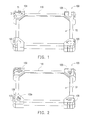
- Fig. 1 is a schematic view of a solar energy device according to one embodiment of the present invention.
- Fig. 2 is a schematic view illustrating the solar energy device of Fig. 1 from another view angle.
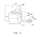
- Fig. 3 is a schematic partially enlarged view illustrating the solar energy device of Fig. 1 being in another state.
- Fig. 4 is a schematic view of a solar energy device according to another embodiment of the present invention.
- Fig. 5 is a schematic partially enlarged view illustrating the solar energy device of Fig. 4 .
- Fig. 1 is a schematic view of a solar energy device according to one embodiment of the present invention.
- Fig. 2 is a schematic view illustrating the solar energy device of Fig. 1 from another view angle.
- Fig. 3 is a schematic partially enlarged view illustrating the solar energy device of Fig. 1 being in another state.
- the solar energy device 100 includes a solar energy module 110 and a plurality of connecting structures 120.
- the solar energy module 110 has a rectangular body and each of the connecting structures 120 is respectively disposed at the four corners of the solar energy module 110.
- the solar energy module can be in other different geometric shapes as required, and the shapes and the configuration of the connecting structures are not limited by the present invention.
- the connecting structure 120 is consisted of a buffer material (e.g., rubber) including a body 122 and a connecting belt 124.
- the body 122 encloses the corners of the solar energy module 110 so as to achieve the buffer effect and protection to the solar energy module 110. That is, regardless of the shape of the solar energy module 110, the connecting structure 120 and the body 122 have the functions of providing a buffer effect, protection from impact and a cushion effect to the solar energy module 110.
- the connecting belt 124 has a first end E1, a second end E2 and a connecting protruding 124a located at the second end E2.
- the first end E1 of the connecting belt 124 is connected to the body 122. It means that the body 122 and the connecting belt 124 can be integrally formed in the manufacturing process of the connecting structure 120.
- the solar energy module 110 has a light receiving surface S1 and a back-lighted surface S2 opposing to the light receiving surface S1.
- the body 122 has a first recess 122a and a second recess 122b opposing to the first recess 122a, wherein the first recess 122a is located at the light receiving surface S1 of the solar energy module 110, the second recess 122b is located at the back-lighted surface S2 of the solar energy module 110, and the first end E1 of the connecting belt 124 is connected to the body 122 located at the light receiving surface S1 and located beside the first recess 122a.
- the connecting belt 124 is detachably embedded in the second recess 122b so that the connecting belt 124 has the same surface profile with the body 122.
- the absolute disposing locations between the recesses 122a, 122b and the connecting belt 124 of the solar energy module 110 are not limited by the present invention.
- Fig. 4 is a schematic view of a solar energy device according to another embodiment of the present invention.
- Fig. 5 is a schematic partially enlarged view illustrating the solar energy device of Fig. 4 .
- the solar energy device 200 includes a plurality of solar energy modules 110 and a plurality of connecting structures 120 disposed on the solar energy modules 110.
- the connecting structures 120 thereof not only have the functions of providing a buffer effect, protection from impact and a cushion effect to the solar energy module 110 as mentioned above embodiment, also can connect multiple solar energy modules 110 together through the connecting structures 124.
- the connecting belt 124 has to be detached from the second recess 122b first (as shown in Fig. 3 ), and then the connecting protruding 124a located at the second end E2 has to be fastened to the first recess 122a of another solar energy module 110 (as shown in Fig. 4 ). Accordingly, the structural connection of the solar energy modules 110 is completed.
- the profiles of the connecting belt 124 of each connecting structure 120 and the connecting protruding 124a are respectively matched with the profile of first recess 122a and the second recess 122b thereof, the different solar energy modules 110 can be connected together with their connecting structures 120.
- the connecting structures can be collocated with the profiles of solar energy modules and a plurality of solar energy modules can be connected together through the connecting method mentioned above.
- the solar energy modules 110 after being connected are not restricted to be on the same plane by the connecting structures 120. Instead, the in-between of the solar energy modules 110 after being connected are in a floating state since the material of the connecting belt 124 is flexible. In other words, the solar energy device 200 after being connected is not a rigid structure.
- the solar energy device 200 can be adaptable to various profiles of rugged surface due to the flexibility of the connecting belt 124. It means that the solar energy device 200 of the present invention can be adaptive to different profiles of the surface where the solar energy device 200 is assembled while the height of solar energy device varies with different terrains. Compared to the conventional solar energy device fabricated with rigid supporting components, the solar energy device 200 of the present invention is more adaptable.
- the solar energy device 200 further includes many pairs of electrodes 130, for example, the positive electrode is disposed in the first recess 122a of the connecting structure 120, and the negative electrode is disposed in the connecting protruding 124a. And the pair of electrodes 130 are electrically connected to the solar energy module 110 disposed by the connecting structure 120.
- the connecting structure 120 on one of the solar energy modules 110 is fastened to the first recess 122a of the connecting structure 120 of another solar energy module 110 through the connecting protruding 124a of the connecting belt 124, the electrical connection between the plurality of solar energy modules 110 can be achieved, through the pair of electrodes, respectively located in the first recess 122a and the connecting protruding 124a, being connected to each other.
- the solar energy device 200 of the present invention is commonly disposed on the ground, when the connecting protruding 124a is fastened to the first recess 122a or the second recess 122b, the distance between the connecting protruding 124a and the solar energy module 110 is smaller than the distance between the top of the first recess 122a of the body 122 and the solar energy module 110, or is smaller than the distance between the top of the second recess 122b of the body 122 and the solar energy module 110.
- the solar energy device 100 placed on the ground is in the status of the first recess 122a being above and the second recess 122b being below, so that the solar energy module 110 can receive lights from the light receiving surface S1.
- the top T1 of the connecting protruding 124a fastened to the body 122 has to be lower than the top T2 of the body 122.
- the pair of electrodes 130 disposed in the connecting protruding 124a and the first recess 122a can be distant from the ground, so as to reduce the bad effect to the electrodes 130 due to humidity. Furthermore as shown in Fig. 5 , when the connecting protruding 124a is fastened to the second recess 122b, the structural effect illustrated in Fig. 1 can also be achieved, and a relevant description is omitted.
- the solar energy module is protected due to the buffer effect.
- the connecting protruding disposed on the connecting belt of the connecting structure and the recess portions of the body the adjacent solar energy modules can be connected to each other, and the plurality of the solar energy modules are further electrically and physically connected together through the connecting structure.
Landscapes
- Engineering & Computer Science (AREA)
- Physics & Mathematics (AREA)
- Life Sciences & Earth Sciences (AREA)
- Sustainable Development (AREA)
- Sustainable Energy (AREA)
- Thermal Sciences (AREA)
- Chemical & Material Sciences (AREA)
- Combustion & Propulsion (AREA)
- Mechanical Engineering (AREA)
- General Engineering & Computer Science (AREA)
- Photovoltaic Devices (AREA)
Abstract
A solar energy device including at least one solar energy module and a connecting structure is provided. The connecting structure includes a body and a connecting belt. The body assembled to the solar energy module has a recess. The connecting belt has a first end, a second end, and a connecting protruding configured at the second end, wherein the first end connects to the body. A using method of the solar energy module is also provided.
Description
- The present invention relates to a solar energy device, and particularly to a solar energy device having a connecting structure.
- With the consideration of environmental protection in recent years, the developments of alternative energy and renewable energy have become popular in response to the shortage of fossil energy and to reduce the impact on environment caused by the use of fossil energy. Herein, photovoltaic cells attract the most attention among the alternative energy and renewable energy. Photovoltaic cells are capable of converting solar energy into electric energy directly without polluting the environment by generating hazardous substances such as carbon dioxide or nitride in the power generation process.
- However, a complicated structure and comparatively more components are required to dispose the solar energy devices to the stage. As a result, the cost of facilitating solar energy by man power and the required components cannot be effectively reduced. Furthermore, most of the supporting components used for mounting the solar energy devices are in rigid structure, and it may lead to the plurality of solar energy devices being restricted to a plane after they are connected to each other, and any appropriate change along with the environmental topography where the solar energy devices are located cannot also be available. Thus, how to effectively simplify the supporting components into a unit and reduce the disposing time, and improve the adaptation of the solar energy device to the environmental topography are the issues deserved further research.
- The present invention provides a solar energy device and the using method thereof, having a connecting structure adapted to the profile of the environmental topography.
- One embodiment of the present invention provides a solar energy device including at least one solar energy module and a connecting structure. The connecting structure includes a body and a connecting belt. The body is assembled to the solar energy module, wherein the body has a first recess. The connecting belt has a first end, a second end and a connecting protruding located at the second end, wherein the first end is connected to the body.
- One embodiment of the present invention provides a using method of a solar energy device adapted to connect the plurality of solar energy devices to each other. Each solar energy device includes a solar energy module and at least one connecting structure assembled to the solar energy module. The connecting structure includes a body, a connecting belt and a pair of electrodes, wherein the body has a first recess, the connecting belt has a first end, a second end and a connecting protruding located at the second end, wherein the first end is connected to the body. The pair of electrodes are respectively disposed at the first recess and the connecting protruding, and electrically connected to the solar energy module. The using method of the solar energy device includes fastening the connecting protruding of one of the solar energy devices in the first recess of another solar energy device, so that the solar energy devices are connected to each other.
- According to an embodiment of the present invention, the solar energy device further includes a pair of electrodes respectively disposed at the first recess and the connecting protruding, and electrically connected to the solar energy module.
- According to an embodiment of the present invention, the solar energy device includes a plurality of solar modules and a plurality of connecting structures. The connecting structures are disposed at the solar energy modules, and the connecting protruding disposed on one of the solar energy modules is fastened to the first recess located at another solar energy module so that the solar energy modules are electrically connected to each other.
- According to an embodiment of the present invention, the body has a second recess, and the second end and the connecting protruding are detachably buried in the second recess.
- According to an embodiment of the present invention, the first recess and the second recess are respectively located at opposite sides of the solar energy module.
- According to an embodiment of the present invention, the first recess is located at a light receiving surface of the solar energy module.
- According to an embodiment of the present invention, the shape of the connecting protruding is matched with the shape of the first recess and the shape of the second recess.
- According to an embodiment of the present invention, when the connecting protruding is fastened to the first recess or the second recess, the distance between the connecting protruding and the solar energy module is smaller than the distance between the top of the first recess of the body and the solar energy module, or is smaller than the distance between the top of the second recess of the body and the solar energy module.
- According to an embodiment of the present invention, the solar energy module has at least one corner, and the body encloses the corner.
- In an embodiment of the present invention, the body is consisted of a buffer material.
- According to an embodiment of the present invention, the connecting belt is flexible.
- In one embodiment of the present invention, the body further has a second recess. The first recess is located at a light receiving surface of the solar energy module. The second recess is located at a back-lighted surface of the solar energy module. And the connecting protruding is detachably buried in the second recess. The using method of the solar energy device further includes detaching the connecting protruding from the second recess located at the back-lighted surface so as to fasten to the first recess of another solar energy device.
- In light of the above, in the embodiment of the present invention, through the connecting structures disposed at the corners of the solar energy module, the solar energy module is protected due to the buffer effect. By using the configuration of the connecting protruding disposed on the connecting belt of the connecting structure and the recess portions of the body, the adjacent solar energy modules can be connected to each other, and the plurality of the solar energy modules are further electrically and/or physically connected together through the connecting structure.
- In order to make the aforementioned and other features and advantages of the invention more comprehensible, embodiments accompanying figures are described in detail below.
- The accompanying drawings constituting a part of this specification are incorporated herein to provide a further understanding of the invention. Here, the drawings illustrate embodiments of the invention and, together with the description, serve to explain the principles of the invention.
-
Fig. 1 is a schematic view of a solar energy device according to one embodiment of the present invention. -
Fig. 2 is a schematic view illustrating the solar energy device ofFig. 1 from another view angle. -
Fig. 3 is a schematic partially enlarged view illustrating the solar energy device ofFig. 1 being in another state. -
Fig. 4 is a schematic view of a solar energy device according to another embodiment of the present invention. -
Fig. 5 is a schematic partially enlarged view illustrating the solar energy device ofFig. 4 . -
Fig. 1 is a schematic view of a solar energy device according to one embodiment of the present invention.Fig. 2 is a schematic view illustrating the solar energy device ofFig. 1 from another view angle.Fig. 3 is a schematic partially enlarged view illustrating the solar energy device ofFig. 1 being in another state. Referring toFig. 1 to Fig. 3 , in the present embodiment, thesolar energy device 100 includes asolar energy module 110 and a plurality of connectingstructures 120. Herein, thesolar energy module 110 has a rectangular body and each of theconnecting structures 120 is respectively disposed at the four corners of thesolar energy module 110. However, in other embodiments not shown in figures, the solar energy module can be in other different geometric shapes as required, and the shapes and the configuration of the connecting structures are not limited by the present invention. - In the present embodiment, the connecting
structure 120 is consisted of a buffer material (e.g., rubber) including abody 122 and aconnecting belt 124. Thebody 122 encloses the corners of thesolar energy module 110 so as to achieve the buffer effect and protection to thesolar energy module 110. That is, regardless of the shape of thesolar energy module 110, the connectingstructure 120 and thebody 122 have the functions of providing a buffer effect, protection from impact and a cushion effect to thesolar energy module 110. - The connecting
belt 124 has a first end E1, a second end E2 and a connecting protruding 124a located at the second end E2. The first end E1 of the connectingbelt 124 is connected to thebody 122. It means that thebody 122 and the connectingbelt 124 can be integrally formed in the manufacturing process of the connectingstructure 120. Herein thesolar energy module 110 has a light receiving surface S1 and a back-lighted surface S2 opposing to the light receiving surface S1. Thebody 122 has afirst recess 122a and asecond recess 122b opposing to thefirst recess 122a, wherein thefirst recess 122a is located at the light receiving surface S1 of thesolar energy module 110, thesecond recess 122b is located at the back-lighted surface S2 of thesolar energy module 110, and the first end E1 of theconnecting belt 124 is connected to thebody 122 located at the light receiving surface S1 and located beside thefirst recess 122a. When thesolar energy device 100 is operating in that state showing inFig. 1 (i.e., thesolar energy device 100 includes only one solar energy module 110), theconnecting belt 124 is detachably embedded in thesecond recess 122b so that theconnecting belt 124 has the same surface profile with thebody 122. However, the absolute disposing locations between therecesses belt 124 of thesolar energy module 110 are not limited by the present invention. -
Fig. 4 is a schematic view of a solar energy device according to another embodiment of the present invention.Fig. 5 is a schematic partially enlarged view illustrating the solar energy device ofFig. 4 . Referring toFig. 4 and Fig. 5 , in the present embodiment, thesolar energy device 200 includes a plurality ofsolar energy modules 110 and a plurality of connectingstructures 120 disposed on thesolar energy modules 110. Likewise, the connectingstructures 120 thereof not only have the functions of providing a buffer effect, protection from impact and a cushion effect to thesolar energy module 110 as mentioned above embodiment, also can connect multiplesolar energy modules 110 together through the connectingstructures 124. - More specifically, when any two of the
solar energy modules 110 have to be connected together, the connectingbelt 124 has to be detached from thesecond recess 122b first (as shown inFig. 3 ), and then the connecting protruding 124a located at the second end E2 has to be fastened to thefirst recess 122a of another solar energy module 110 (as shown inFig. 4 ). Accordingly, the structural connection of thesolar energy modules 110 is completed. In other words, since the profiles of the connectingbelt 124 of each connectingstructure 120 and the connecting protruding 124a are respectively matched with the profile offirst recess 122a and thesecond recess 122b thereof, the differentsolar energy modules 110 can be connected together with their connectingstructures 120. - Please refer to
Fig. 5 again. In order to connect thesolar energy modules 110 together as shown in the status ofFig. 4 , on the same connectingstructure 120, the orthogonal projections to the plane where thesolar energy module 110 is located of the extension direction D1 of the connecting belt 124 (i.e., the extension direction of thesecond recess 122b) and the extension direction D2 of thefirst recess 122a are perpendicular to each other. As such, the neighboring foursolar energy modules 110 can be connected together by connecting the connectingbelts 124 end to end, and such connection can be continuously expanded. However, the present invention is not limited thereto. In other embodiments not shown in figures, the connecting structures can be collocated with the profiles of solar energy modules and a plurality of solar energy modules can be connected together through the connecting method mentioned above. - It should be noted that, in the embodiment, the
solar energy modules 110 after being connected are not restricted to be on the same plane by the connectingstructures 120. Instead, the in-between of thesolar energy modules 110 after being connected are in a floating state since the material of the connectingbelt 124 is flexible. In other words, thesolar energy device 200 after being connected is not a rigid structure. By contrast, thesolar energy device 200 can be adaptable to various profiles of rugged surface due to the flexibility of the connectingbelt 124. It means that thesolar energy device 200 of the present invention can be adaptive to different profiles of the surface where thesolar energy device 200 is assembled while the height of solar energy device varies with different terrains. Compared to the conventional solar energy device fabricated with rigid supporting components, thesolar energy device 200 of the present invention is more adaptable. - Please refer to
Fig. 2 ,Fig. 3 andFig. 5 again. On the other hand, thesolar energy device 200 further includes many pairs ofelectrodes 130, for example, the positive electrode is disposed in thefirst recess 122a of the connectingstructure 120, and the negative electrode is disposed in the connecting protruding 124a. And the pair ofelectrodes 130 are electrically connected to thesolar energy module 110 disposed by the connectingstructure 120. Therefore, when the connectingstructure 120 on one of thesolar energy modules 110 is fastened to thefirst recess 122a of the connectingstructure 120 of anothersolar energy module 110 through the connecting protruding 124a of the connectingbelt 124, the electrical connection between the plurality ofsolar energy modules 110 can be achieved, through the pair of electrodes, respectively located in thefirst recess 122a and the connecting protruding 124a, being connected to each other. - In addition, since the
solar energy device 200 of the present invention is commonly disposed on the ground, when the connecting protruding 124a is fastened to thefirst recess 122a or thesecond recess 122b, the distance between the connecting protruding 124a and thesolar energy module 110 is smaller than the distance between the top of thefirst recess 122a of thebody 122 and thesolar energy module 110, or is smaller than the distance between the top of thesecond recess 122b of thebody 122 and thesolar energy module 110. For instance, referring toFig 1 , after the connecting protruding 124a is fastened to thesecond recess 122b, thesolar energy device 100 placed on the ground is in the status of thefirst recess 122a being above and thesecond recess 122b being below, so that thesolar energy module 110 can receive lights from the light receiving surface S1. At this moment, since thebody 122 located at the back-lighted surface S2 may contact with the ground through the top T2 of thebody 122, the top T1 of the connecting protruding 124a fastened to thebody 122 has to be lower than the top T2 of thebody 122. As such, the pair ofelectrodes 130 disposed in the connecting protruding 124a and thefirst recess 122a can be distant from the ground, so as to reduce the bad effect to theelectrodes 130 due to humidity. Furthermore as shown inFig. 5 , when the connecting protruding 124a is fastened to thesecond recess 122b, the structural effect illustrated inFig. 1 can also be achieved, and a relevant description is omitted. - In light of the foregoing, in the embodiment of the present invention, through the connecting structures disposed at the corners of the solar energy module, the solar energy module is protected due to the buffer effect. By using the configuration of the connecting protruding disposed on the connecting belt of the connecting structure and the recess portions of the body, the adjacent solar energy modules can be connected to each other, and the plurality of the solar energy modules are further electrically and physically connected together through the connecting structure.
- Although the invention has been described with reference to the above embodiments, it will be apparent to one of the ordinary skill in the art that modifications to the described embodiment may be made without departing from the spirit of the invention. Accordingly, the scope of the invention will be defined by the attached claims not by the above detailed descriptions.
Claims (13)
- A solar energy device (100, 200), comprising:at least one solar energy module (110);a connecting structure (120), comprising:a body (122) assembled to the solar energy module (110), wherein the body (122) has a first recess (122a) ; anda connecting belt (124) having a first end (E1), a second end (E2) and a connecting protruding (124a) located at the second end (E2), wherein the first end (E1) is connected to the body (122).
- The solar energy device (100, 200) as claimed in claim 1, further comprising:a pair of electrodes (130) respectively disposed at the first recess (122a) and the connecting protruding (124a), and electrically connected to the solar energy module (110).
- The solar energy device (100, 200) as claimed in claim 2, further comprising:a plurality of solar energy modules (110); anda plurality of connecting structures (120) disposed at the solar energy modules(110), and the connecting protruding (124a) disposed on one of the solar energy modules (110) being fastened to the first recess (122a) located at another solar energy module (110) so that the solar energy modules (110) are electrically connected to each other.
- The solar energy device (100, 200) as claimed in claim 1, wherein the body (122) has a second recess(122b), and the second end (E2) and the connecting protruding (124a) are detachably buried in the second recess(122b).
- The solar energy device (100, 200) as claimed in claim 4, wherein the first recess (122a) and the second recess (122b) are respectively located at opposite sides of the solar energy module(110).
- The solar energy device (100, 200) as claimed in claim 5, wherein the first recess (122a) is located at a light receiving surface (S1) of the solar energy module (110).
- The solar energy device (100, 200) as claimed in claim 4, wherein the shape of the connecting protruding (124a) is matched with the shape of the first recess (122a) and the shape of the second recess (122b).
- The solar energy device (100, 200) as claimed in claim 4, wherein when the connecting protruding (124a) is fastened to the first recess (122a) or the second recess (122b), the distance between the connecting protruding (124a) and the solar energy module (110) is smaller than the distance between the top (T2) of the first recess (122a) of the body (122) and the solar energy module(110), or is smaller than the distance between the top of the second recess (122b) of the body (122) and the solar energy module (110).
- The solar energy device (100, 200) as claimed in claim 1, wherein the solar energy module (110) has at least one corner, and the body (120) encloses the corner.
- The solar energy device (100, 200) as claimed in claim 9, wherein the body (120) comprises a buffer material.
- The solar energy device (100, 200) as claimed in claim 10, wherein the connecting belt (124) is flexible.
- A using method of a solar energy device(100, 200), adapted to connect a plurality of solar energy devices (100, 200) to each other, each solar energy device (100, 200) comprising a solar energy module (110) and at least one connecting structure (120) assembled to the solar energy module (110), and the connecting structure (120) comprising a body (122), a connecting belt (124) and a pair of electrodes (130), wherein the body (122) has a first recess (122a), the connecting belt (124) has a first end (E1), a second end (E2) and a connecting protruding (124a) located at the second end (E2), and the first end (E1) is connected to the body (120), the pair of electrodes (130) are respectively disposed at the first recess (122a) and the connecting protruding (124a) and electrically connected to the solar energy module (110), the using method of the solar energy device (100, 200) comprising:fastening the connecting protruding (124a) of one of the solar energy devices (100, 200) to the first recess (122a) of another solar energy device (100, 200) so that the solar energy devices (100, 200) are connected to each other.
- The using method of the solar energy device (100, 200) as claimed in claim 12, wherein the body (122) further has a second recess (122b), the first recess (122a) is located at a light receiving surface (S1) of the solar energy module (110), the second recess (122b) is located at a back-lighted surface (S2) of the solar energy module (110), and the connecting protruding (124a) is detachably buried in the second recess (122b), the using method of the solar energy device (100, 200) further comprises:detaching the connecting protruding (124a) from the second recess (122b) located at the back-lighted surface (S2) so as to fasten to the first recess (122a) of another solar energy device (100, 200).
Priority Applications (1)
| Application Number | Priority Date | Filing Date | Title |
|---|---|---|---|
| EP11187536.5A EP2590225A1 (en) | 2011-11-02 | 2011-11-02 | Solar energy device and using method of the same |
Applications Claiming Priority (1)
| Application Number | Priority Date | Filing Date | Title |
|---|---|---|---|
| EP11187536.5A EP2590225A1 (en) | 2011-11-02 | 2011-11-02 | Solar energy device and using method of the same |
Publications (1)
| Publication Number | Publication Date |
|---|---|
| EP2590225A1 true EP2590225A1 (en) | 2013-05-08 |
Family
ID=44970964
Family Applications (1)
| Application Number | Title | Priority Date | Filing Date |
|---|---|---|---|
| EP11187536.5A Withdrawn EP2590225A1 (en) | 2011-11-02 | 2011-11-02 | Solar energy device and using method of the same |
Country Status (1)
| Country | Link |
|---|---|
| EP (1) | EP2590225A1 (en) |
Cited By (3)
| Publication number | Priority date | Publication date | Assignee | Title |
|---|---|---|---|---|
| EP3080526A4 (en) * | 2014-01-22 | 2017-06-21 | Pegasus Solar Inc. | Corner connection bracket for solar energy panels |
| USD823786S1 (en) | 2015-03-31 | 2018-07-24 | Pegasus Solar Inc. | Asymmetrical solar panel bracket assembly |
| US10505492B2 (en) | 2016-02-12 | 2019-12-10 | Solarcity Corporation | Building integrated photovoltaic roofing assemblies and associated systems and methods |
Citations (3)
| Publication number | Priority date | Publication date | Assignee | Title |
|---|---|---|---|---|
| US20070215200A1 (en) * | 2006-03-17 | 2007-09-20 | Korea Institute Of Energy Research | Blind type solar cell and array thereof |
| US20080113567A1 (en) * | 2006-11-15 | 2008-05-15 | Solyndra, Inc. | Apparatus and methods for connecting multiple photovoltaic modules |
| US20100275976A1 (en) * | 2007-12-18 | 2010-11-04 | Day4 Energy Inc. | Photovoltaic module with edge access to pv strings, interconnection method, apparatus, and system |
-
2011
- 2011-11-02 EP EP11187536.5A patent/EP2590225A1/en not_active Withdrawn
Patent Citations (3)
| Publication number | Priority date | Publication date | Assignee | Title |
|---|---|---|---|---|
| US20070215200A1 (en) * | 2006-03-17 | 2007-09-20 | Korea Institute Of Energy Research | Blind type solar cell and array thereof |
| US20080113567A1 (en) * | 2006-11-15 | 2008-05-15 | Solyndra, Inc. | Apparatus and methods for connecting multiple photovoltaic modules |
| US20100275976A1 (en) * | 2007-12-18 | 2010-11-04 | Day4 Energy Inc. | Photovoltaic module with edge access to pv strings, interconnection method, apparatus, and system |
Cited By (4)
| Publication number | Priority date | Publication date | Assignee | Title |
|---|---|---|---|---|
| EP3080526A4 (en) * | 2014-01-22 | 2017-06-21 | Pegasus Solar Inc. | Corner connection bracket for solar energy panels |
| US10024580B2 (en) | 2014-01-22 | 2018-07-17 | Pegasus Solar Inc. | Corner connection bracket for solar energy panels |
| USD823786S1 (en) | 2015-03-31 | 2018-07-24 | Pegasus Solar Inc. | Asymmetrical solar panel bracket assembly |
| US10505492B2 (en) | 2016-02-12 | 2019-12-10 | Solarcity Corporation | Building integrated photovoltaic roofing assemblies and associated systems and methods |
Similar Documents
| Publication | Publication Date | Title |
|---|---|---|
| US8653359B2 (en) | Solar energy device and using method of the same | |
| JP5938584B2 (en) | Solar cell module | |
| CN111699627A (en) | Power wiring device | |
| EP2284929B8 (en) | Battery module | |
| CN110021721A (en) | Battery modules and automobile | |
| US9099587B2 (en) | Educational solar cell module | |
| US10134935B2 (en) | Photoelectric conversion apparatus and photoelectric conversion unit used in photoelectric conversion apparatus | |
| ATE557430T1 (en) | SECONDARY BATTERY WITH PROTECTION CIRCUIT MODULE | |
| JP2011509424A (en) | Display system with solar cell and device having the same | |
| WO2008139610A1 (en) | Solar battery module device | |
| EP2747151A2 (en) | Apparatus for photovoltaic power generation | |
| MY159905A (en) | Solar battery module | |
| EP1744372A2 (en) | Solar panel | |
| US20100108120A1 (en) | Multi-stage folding portable solar charging apparatus | |
| CN106464202B (en) | Device of solar generating | |
| US9972726B2 (en) | Photovoltaic apparatus | |
| EP2605288A2 (en) | Solar cell and solar cell module | |
| JP2011044242A (en) | Connectable socket device | |
| KR20190005646A (en) | Portable Charger | |
| JP2013225644A (en) | Solar cell device | |
| CN111146233A (en) | display device | |
| EP2341552A2 (en) | Supporting structure for supporting a plurality of solar panels and related solar tile module | |
| KR101926989B1 (en) | solar cell assembly | |
| KR101326953B1 (en) | Solar cell module | |
| KR20130076371A (en) | Solar cell module |
Legal Events
| Date | Code | Title | Description |
|---|---|---|---|
| PUAI | Public reference made under article 153(3) epc to a published international application that has entered the european phase |
Free format text: ORIGINAL CODE: 0009012 |
|
| AK | Designated contracting states |
Kind code of ref document: A1 Designated state(s): AL AT BE BG CH CY CZ DE DK EE ES FI FR GB GR HR HU IE IS IT LI LT LU LV MC MK MT NL NO PL PT RO RS SE SI SK SM TR |
|
| AX | Request for extension of the european patent |
Extension state: BA ME |
|
| STAA | Information on the status of an ep patent application or granted ep patent |
Free format text: STATUS: THE APPLICATION IS DEEMED TO BE WITHDRAWN |
|
| 18D | Application deemed to be withdrawn |
Effective date: 20131109 |