EP2590004A1 - Lens driving unit, and lens apparatus and image pickup apparatus including the same - Google Patents
Lens driving unit, and lens apparatus and image pickup apparatus including the same Download PDFInfo
- Publication number
- EP2590004A1 EP2590004A1 EP12007157.6A EP12007157A EP2590004A1 EP 2590004 A1 EP2590004 A1 EP 2590004A1 EP 12007157 A EP12007157 A EP 12007157A EP 2590004 A1 EP2590004 A1 EP 2590004A1
- Authority
- EP
- European Patent Office
- Prior art keywords
- lens
- movable
- movable member
- fixed
- driving unit
- Prior art date
- Legal status (The legal status is an assumption and is not a legal conclusion. Google has not performed a legal analysis and makes no representation as to the accuracy of the status listed.)
- Withdrawn
Links
- 230000003287 optical effect Effects 0.000 claims abstract description 53
- 125000006850 spacer group Chemical group 0.000 claims abstract description 8
- 238000011105 stabilization Methods 0.000 description 21
- 230000006641 stabilisation Effects 0.000 description 13
- 238000000034 method Methods 0.000 description 8
- 230000000717 retained effect Effects 0.000 description 8
- 230000000694 effects Effects 0.000 description 6
- 230000007774 longterm Effects 0.000 description 4
- 239000000696 magnetic material Substances 0.000 description 4
- 230000000087 stabilizing effect Effects 0.000 description 3
- 238000001514 detection method Methods 0.000 description 2
- 238000006073 displacement reaction Methods 0.000 description 2
- 238000005516 engineering process Methods 0.000 description 2
- 238000005096 rolling process Methods 0.000 description 2
- 238000005452 bending Methods 0.000 description 1
- 238000006243 chemical reaction Methods 0.000 description 1
- 230000005284 excitation Effects 0.000 description 1
- 238000003384 imaging method Methods 0.000 description 1
- 230000014759 maintenance of location Effects 0.000 description 1
- 238000012986 modification Methods 0.000 description 1
- 230000004048 modification Effects 0.000 description 1
Images



Classifications
-
- G—PHYSICS
- G02—OPTICS
- G02B—OPTICAL ELEMENTS, SYSTEMS OR APPARATUS
- G02B27/00—Optical systems or apparatus not provided for by any of the groups G02B1/00 - G02B26/00, G02B30/00
- G02B27/64—Imaging systems using optical elements for stabilisation of the lateral and angular position of the image
- G02B27/646—Imaging systems using optical elements for stabilisation of the lateral and angular position of the image compensating for small deviations, e.g. due to vibration or shake
-
- G—PHYSICS
- G03—PHOTOGRAPHY; CINEMATOGRAPHY; ANALOGOUS TECHNIQUES USING WAVES OTHER THAN OPTICAL WAVES; ELECTROGRAPHY; HOLOGRAPHY
- G03B—APPARATUS OR ARRANGEMENTS FOR TAKING PHOTOGRAPHS OR FOR PROJECTING OR VIEWING THEM; APPARATUS OR ARRANGEMENTS EMPLOYING ANALOGOUS TECHNIQUES USING WAVES OTHER THAN OPTICAL WAVES; ACCESSORIES THEREFOR
- G03B5/00—Adjustment of optical system relative to image or object surface other than for focusing
- G03B5/02—Lateral adjustment of lens
-
- G—PHYSICS
- G03—PHOTOGRAPHY; CINEMATOGRAPHY; ANALOGOUS TECHNIQUES USING WAVES OTHER THAN OPTICAL WAVES; ELECTROGRAPHY; HOLOGRAPHY
- G03B—APPARATUS OR ARRANGEMENTS FOR TAKING PHOTOGRAPHS OR FOR PROJECTING OR VIEWING THEM; APPARATUS OR ARRANGEMENTS EMPLOYING ANALOGOUS TECHNIQUES USING WAVES OTHER THAN OPTICAL WAVES; ACCESSORIES THEREFOR
- G03B2205/00—Adjustment of optical system relative to image or object surface other than for focusing
- G03B2205/0007—Movement of one or more optical elements for control of motion blur
- G03B2205/0015—Movement of one or more optical elements for control of motion blur by displacing one or more optical elements normal to the optical axis
-
- G—PHYSICS
- G03—PHOTOGRAPHY; CINEMATOGRAPHY; ANALOGOUS TECHNIQUES USING WAVES OTHER THAN OPTICAL WAVES; ELECTROGRAPHY; HOLOGRAPHY
- G03B—APPARATUS OR ARRANGEMENTS FOR TAKING PHOTOGRAPHS OR FOR PROJECTING OR VIEWING THEM; APPARATUS OR ARRANGEMENTS EMPLOYING ANALOGOUS TECHNIQUES USING WAVES OTHER THAN OPTICAL WAVES; ACCESSORIES THEREFOR
- G03B2205/00—Adjustment of optical system relative to image or object surface other than for focusing
- G03B2205/0053—Driving means for the movement of one or more optical element
Definitions
- the present invention relates to a lens driving unit including a driving unit.
- a lens apparatus including a correction lens that is moved in a translational movement in a plane perpendicular to an optical axis so as to suppress an image shake is well known, and an apparatus including a retention mechanism for restricting and fixing movement of a movable member including the correction lens when image stabilization is not performed is also known.
- Japanese Patent No. 4,011,576 discloses an apparatus in which, when the image stabilization is not performed, the movable member including the correction lens is rotated so that a locking element reception portion of a fixed member and a locking element of the movable member are engaged at a predetermined position, and hence the movable member is locked at a position matching an optical axis. In this position, the movable member is biased toward the locking element reception portion by a magnetic repulsion force, and hence the position is retained.
- Japanese Patent Application Laid-Open No. 2008-015349 discloses an apparatus in which the movable member is retained at a position by a magnetic attraction force in the state where the movable member including the correction lens is locked with the fixed member by the same method as disclosed in Japanese Patent No. 4,011,576 .
- a posture of the correction lens is mechanically determined when the locking element of the movable member abuts on the locking element reception portion of the fixed member. Therefore, in a locked state, the posture of the correction lens is determined with a deviation from the optical axis by a play of the locking element in a radial direction, and thus the optical performance is deteriorated.
- wear or deformation occurs in the locking element, and hence positioning accuracy of the correction lens is deteriorated with time.
- the shape of a component is complicated, which causes an increase of cost.
- the present invention provides a lens driving unit capable of simplifying the shape of the component, positioning the correction lens accurately, and reducing the change in positioning accuracy of the correction lens with time in a long-term use.
- a lens driving unit for moving a lens in a lens apparatus in a direction perpendicular to an optical axis of the lens apparatus, the lens driving unit including: a fixed member; a movable member to which the lens is fixed; a spacer interposed between the fixed member and the movable member in a state where the fixed member and the movable member are movable relatively to each other in the direction perpendicular to the optical axis of the lens; a biasing unit for biasing the movable member toward the fixed member; a position detector for detecting a position of the movable member with respect to the fixed member in a plane perpendicular to the optical axis of the lens; a driving unit for driving the movable member with respect to the fixed member in the direction perpendicular to the optical axis; a controller for controlling the drive unit to drive the movable member based on the position of the movable member detected by the position detector; and a movable range
- the lens driving unit capable of further simplifying the shape of the component, positioning the correction lens accurately, and reducing the change in positioning accuracy of the correction lens with time in a long-term use.
- FIG. 1 is an exploded perspective view of a lens driving unit according to a first embodiment of the present invention.
- FIG. 2A is a front view of the lens driving unit when image stabilization is performed according to the first embodiment.
- FIG. 2B is a front view of the lens driving unit when the image stabilization is not performed according to the first embodiment.
- FIG. 3 is a schematic top view of FIG. 2A .
- FIG. 4 is a partially enlarged view of a drive unit and the vicinity thereof according to the first embodiment.
- FIG. 5 is a flowchart to be performed when a movable unit is locked according to the first embodiment.
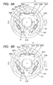
- FIG. 6A is a front view of a lens driving unit when the image stabilization is performed according to a second embodiment of the present invention.
- FIG. 6B is a front view of the lens driving unit when the image stabilization is not performed according to the second embodiment.
- FIG. 7 is a partially enlarged view of the drive unit and the vicinity thereof according to the second embodiment.
- FIGS. 1 to 5 a lens driving unit according to a first embodiment of the present invention is described in detail.
- FIG. 1 is an exploded perspective view of a lens driving unit according to the first embodiment.
- FIG. 2A is a front view of the lens driving unit when an image stabilizing function is effective (hereinafter referred to as "image-stabilization state").
- FIG. 2B is a front view of the lens driving unit when the image stabilization is not performed (hereinafter referred to as "no-image-stabilization state").
- FIGS. 2A and 2B in order to facilitate understanding of the structure, a fixed unit and balls described later are indicated by solid lines while a movable unit is indicated by broken lines.
- FIG. 3 is a schematic top view of FIG. 2A , for illustrating a structure of the drive unit and the vicinity thereof in a simplified manner.
- FIG. 4 is a partially enlarged view of FIG. 3 . Note that, a voice coil motor that is usually known is used as a driving unit in this embodiment.
- a lens driving unit 1 includes a fixed unit (fixed member) 2 fixed integrally with a lens barrel or the like in a lens apparatus for imaging (not shown), a movable unit (movable member) 3 that includes a correction lens 31 and changes its relative position with respect to the fixed unit 2, and three balls (spacers) 4 interposed between the movable unit 3 and the fixed unit 2.
- the fixed unit 2 includes a retaining plate 21 as a reference member for the lens driving unit 1, three attraction yokes 22 fixed to the retaining plate 21 at substantially every 120 degrees, and three driving coils 23 fixed to the attraction yokes 22.
- the fixed unit 2 includes three position detectors 24 for detecting a position of the movable unit 3, and ball reception portions 25 for receiving the three balls 4 disposed between the fixed unit 2 and the movable unit 3.
- the retaining plate 21 includes a fitting portion 211 to which a protrusion 321 of a moving plate 32 of the movable unit 3 described later is fitted with a predetermined play when the image stabilization is not performed, and a fit release portion 212 for releasing the fit with the protrusion 321 of the moving plate 32 when the image stabilization is performed.
- the fitting portion 211, the fit release portion 212, and the protrusion 321 of the fixed unit 2 and the movable unit 3 constitute a movable range defining unit, which defines a movable position having a large relative movable range in a plane perpendicular to the optical axis and a fixed position having a small relative movable range in the plane perpendicular to the optical axis based on a relative rotation position about the optical axis of the correction lens 31 retained by the moving plate 32.
- the movable unit 3 includes the moving plate 32 made of a non-magnetic material and retaining the correction lens 31 for performing the image stabilization, the protrusions 321 disposed on the moving plate 32, permanent magnets 33, and back yokes 34 disposed on the permanent magnets 33 on the moving plate 32 side.
- the permanent magnet 33 is magnetized so as to have the north pole on one side and the south pole on the other side with respect to the center line as a boundary as illustrated in FIGS. 3 and 4 , and is interposed between the attraction yoke 22 and the back yoke 34 so as to form a closed magnetic circuit as illustrated in FIG. 4 .
- a belt-shaped position detecting scale 35 is disposed at a position opposed to the position detectors 24.
- the position detecting scale 35 has a size which is large enough for the position detectors 24 of the fixed unit 2 to face the position detecting scale 35 even if the movable unit 3 moves in the maximum movable range.
- the attraction yoke 22 and the driving coil 23 of the fixed unit 2, and the permanent magnet 33 and the back yoke 34 of the movable unit 3 are integrally referred to as a drive unit 5.
- the movable unit 3 is attracted to the fixed unit 2 so that the permanent magnet 33 attracts the attraction yoke 22 made of a magnetic material.
- the three balls 4 are interposed between the retaining plate 21 and the moving plate 32 while being housed in holes of the ball reception portions 25 disposed in the retaining plate 21.
- the ball 4 rotates in the hole of the ball reception portion 25 along with movement of the moving plate 32 so as to support the moving plate 32 with respect to the fixed unit 2 in a plane perpendicular to the optical axis in a movable state and to always maintain a constant distance between the moving plate 32 and the retaining plate 21.
- the center of the driving coil 23 is on the center line of the permanent magnet 33.
- the permanent magnet 33 exhibits a magnetic force illustrated by lines of a magnetic force as indicated by arrows in FIG. 4 .
- the driving coil 23 is applied with electric current, an electromagnetic force is generated.
- a direction and intensity of the generated force can be adjusted by a direction and quantity of the applied current.
- the electric current flowing in the clockwise direction causes a force for moving the movable unit 3 in a clockwise direction
- the electric current flowing in the counterclockwise direction causes a force for moving the movable unit 3 in a counterclockwise direction.
- a vibration amount is first input from a vibration detection sensor of a camera or lens body (not shown) to a CPU for the lens driving unit serving as a drive controller (not shown).
- the CPU calculates a drive amount of the correction lens necessary for stabilizing the image based on the input vibration amount and outputs the drive amount based on the calculated drive amount as electric current signal to the three drive units 5.
- the drive unit 5 drives the moving plate 32 to move in translational movement in the plane perpendicular to the optical axis based on the electric current signal. Position information of the moving plate 32 is detected by reading the position detecting scale 35 by the three position detectors 24, and the position information is fed back to the CPU.
- the CPU calculates the drive amount of the correction lens 31 based on the fed-back position information and a newly input vibration amount from the vibration detection sensor, and outputs the electric current signal based on the calculated drive amount to the drive unit 5.
- the lens driving unit 1 continuously performs the image stabilization.
- FIG. 5 is a flowchart illustrating a method of controlling the movable unit 3 to a locked state.
- the CPU calculates a drive amount necessary for adjusting the optical axis of the correction lens 31 coincident with the optical axis of the lens apparatus from optical axis center information of the lens apparatus recorded in advance and the position information of the moving plate 32. After that, the calculated drive amount is converted into the current signal, and the electric current signal is output to each drive unit 5 (S101).
- Each drive unit 5 drives the moving plate 32 to move in translational movement to a position where the optical axis of the correction lens 31 is coincident with the optical axis of the lens apparatus based on the electric current signal (S102 and S103).
- the moving plate 32 is rotated about the optical axis by a predetermined amount to a position (lock position) where a phase of the protrusion 321 of the movable unit 3 is coincident with a phase of the fitting portion 211 of the fixed unit 2 (S104).
- the position detector 24 detects that the moving plate 32 has rotated to the lock position (S105)
- the CPU stops energization to the drive unit 5 (S106).
- the permanent magnets 33 continuously attract the attraction yokes 22 so that the movable unit 3 maintains the state of causing the three balls 4 to be biased toward the holes of the ball reception portions 25 in the retaining plate 21 by a predetermined biasing force even when the energization is not performed.
- the posture of the movable unit 3 is maintained in the non-image-stabilization state, and hence it is possible to retain the position of the optical axis of the correction lens 31 at the position coincident with the optical axis of the lens apparatus.
- the retaining plate 21 (fixed unit 2) includes the ball reception portions 25 in this case, but the same effect can be obtained also when the moving plate 32 (movable unit 3) includes the ball reception portions 25.
- the position of the movable unit 3 can be retained without a significant deviation of the optical axis of the correction lens 31 from the optical axis of the lens apparatus (reference position). Note that, if a deviation of the position of the movable unit 3 occurs in a state where the lens apparatus is powered on, the CPU detects a change of an output value of the position detector and controls the drive unit 5 to move the movable unit 3 to a position where the optical axis of the correction lens 31 is coincident with the optical axis of the lens apparatus.
- the CPU calculates an amount of positional deviation (an amount of movement from the reference position including a direction and a distance) from a change of the output value of the position detector, and controls the drive unit 5 to move the movable unit 3 to the position where the optical axis of the correction lens 31 is coincident with the optical axis of the lens apparatus.
- the position of the movable unit 3 including the correction lens can be retained at a position where the optical axis of the correction lens 31 is coincident with the optical axis of the lens apparatus. Therefore, good optical performance can be obtained.
- the attraction yoke and the driving coil are disposed on the fixed unit while the permanent magnet and the back yoke are disposed on the movable unit in this embodiment, but the same effect can be obtained also when the permanent magnet and the back yoke are disposed on the fixed unit while the driving coil and the attraction yoke are disposed on the movable unit as a counterpart.
- the effect of the yoke can be obtained by using a magnetic material for the moving plate, the back yoke becomes unnecessary so that the number of components can further be reduced.
- the movable unit 3 is controlled to rotate to the lock position, but it is possible to simultaneously control the translational movement to the optical axis center of the correction lens 31 and the rotational movement to the lock position.
- FIGS. 6A, 6B , and 7 a second embodiment of the present invention is described in detail with reference to FIGS. 6A, 6B , and 7 .
- a drive unit has a structure different from that in the first embodiment.
- Other identical parts are denoted by the same reference numerals or symbols, and description thereof is omitted.
- a drive unit 8 of this embodiment includes three vibrational wave motors 63 fixed to a retaining plate 61 through an intermediation of leaf springs 62 substantially at every 120 degrees about the optical axis position of the correction lens 31, and three attraction magnets 64.
- a movable unit 7 of this embodiment includes a slider 72 which is held in contact with the vibrational wave motor 63 and is fixed to a moving plate 71, and attraction plates 73 which are made of a magnetic material and are disposed at positions corresponding to the three attraction magnets 64.
- the vibrational wave motor 63 includes a vibration portion 631 having an electromechanical energy conversion element, and a contact portion 632 formed integrally with the vibration portion 631 so as to come into contact with a portion to be driven.
- the vibration portion 631 generates a bending vibration and a stretching vibration through excitation, for example, and displacements caused by the individual vibrations are combined so that an ellipse or circle movement is generated at a tip of the contact portion 632. Then, the vibration movement is transmitted to the slider 72 via a friction force of the contact portion 632 so that a drive force can be generated.
- the three balls 4 are interposed between the retaining plate 61 and the moving plate 71, and the attraction magnet 64 attracts the attraction plate 73.
- the movable unit 7 is supported in a relatively movable manner in a plane perpendicular to the optical axis while always maintaining a constant distance.
- FIG. 7 is a cross-sectional view of the vibrational wave motor 63 and the vicinity thereof.
- the vibrational wave motor 63 is held in contact with the slider 72 of the moving plate 71 in a state where the leaf springs 62 fixed to the retaining plate 61 are bent.
- the contact portion 632 always receives a biasing force from the leaf spring 62 in a direction A in FIG. 7 so as to be held in contact with the slider 72, and a friction force always works on the contact surface.
- the vibrational wave motor 63 When the vibrational wave motor 63 performs the vibration movement, a drive force is transmitted to the slider 72 in a direction B so as to move the movable unit 7.
- the three vibrational wave motors 63 respectively perform the above-mentioned vibration movement to move the moving plate 71 in translational movement and rotate in the plane perpendicular to the optical axis.
- a method of locking the movable unit 7 in the non-image-stabilization state the same control as in the first embodiment ( FIG. 5 ) is performed, in which the movable unit 7 is rotated by a predetermined amount to a position at which the movable unit 7 is fitted with the fixed unit 6, and then the energization to the drive unit 8 is stopped so that the position of the correction lens 31 is retained.
- the contact portion 632 of the vibrational wave motor 63 is always held in contact with the slider 72 of the movable unit 7 even when the energization is stopped, and hence the sliding friction force working constantly between the contact portion 632 and the slider 72 works as a retaining force for retaining the posture of the movable unit 7 with respect to the fixed unit 6.
- the retaining force by the sliding friction force of the contact portion 632 of the vibrational wave motor works constantly on the movable unit 7 even in the state without energization. Therefore, the optical axis of the movable unit 7 can be retained more securely at the position coincident with the optical axis of the lens apparatus.
- the lens driving unit of the present invention By applying the lens driving unit of the present invention to an image stabilizing mechanism of the lens apparatus, or by using an image pickup apparatus including the lens apparatus to which the lens driving unit of the present invention is applied, it is possible to realize the lens apparatus and the image pickup apparatus that can provide the effect of the present invention.
Landscapes
- Physics & Mathematics (AREA)
- General Physics & Mathematics (AREA)
- Optics & Photonics (AREA)
- Adjustment Of Camera Lenses (AREA)
- Studio Devices (AREA)
Abstract
Description
- The present invention relates to a lens driving unit including a driving unit.
- Conventionally, a lens apparatus including a correction lens that is moved in a translational movement in a plane perpendicular to an optical axis so as to suppress an image shake is well known, and an apparatus including a retention mechanism for restricting and fixing movement of a movable member including the correction lens when image stabilization is not performed is also known.
- Japanese Patent No.
4,011,576 - Japanese Patent Application Laid-Open No.
2008-015349 4,011,576 - However, in the conventional technologies disclosed in Japanese Patent Application Laid-Open No.
2008-015349 4,011,576 - Therefore, the present invention provides a lens driving unit capable of simplifying the shape of the component, positioning the correction lens accurately, and reducing the change in positioning accuracy of the correction lens with time in a long-term use.
- According to an exemplary embodiment of the present invention, there is provided a lens driving unit for moving a lens in a lens apparatus in a direction perpendicular to an optical axis of the lens apparatus, the lens driving unit including: a fixed member; a movable member to which the lens is fixed; a spacer interposed between the fixed member and the movable member in a state where the fixed member and the movable member are movable relatively to each other in the direction perpendicular to the optical axis of the lens; a biasing unit for biasing the movable member toward the fixed member; a position detector for detecting a position of the movable member with respect to the fixed member in a plane perpendicular to the optical axis of the lens; a driving unit for driving the movable member with respect to the fixed member in the direction perpendicular to the optical axis; a controller for controlling the drive unit to drive the movable member based on the position of the movable member detected by the position detector; and a movable range defining unit for defining a movable position having a large relative movable range between the fixed member and the movable member in the plane perpendicular to the optical axis and a fixed position having a small relative movable range between the fixed member and the movable member in the plane perpendicular to the optical axis based on a relative rotation position of the fixed member and the movable member about the optical axis of the lens, in which, in the fixed position, a sliding friction force is generated between the spacer and one of the fixed member and the movable member, or between the driving unit and the movable member.
- According to the present invention, it is possible to provide the lens driving unit capable of further simplifying the shape of the component, positioning the correction lens accurately, and reducing the change in positioning accuracy of the correction lens with time in a long-term use.
- Further features of the present invention will become apparent from the following description of exemplary embodiments with reference to the attached drawings.
-
FIG. 1 is an exploded perspective view of a lens driving unit according to a first embodiment of the present invention. -
FIG. 2A is a front view of the lens driving unit when image stabilization is performed according to the first embodiment. -
FIG. 2B is a front view of the lens driving unit when the image stabilization is not performed according to the first embodiment. -
FIG. 3 is a schematic top view ofFIG. 2A . -
FIG. 4 is a partially enlarged view of a drive unit and the vicinity thereof according to the first embodiment. -
FIG. 5 is a flowchart to be performed when a movable unit is locked according to the first embodiment. -
FIG. 6A is a front view of a lens driving unit when the image stabilization is performed according to a second embodiment of the present invention. -
FIG. 6B is a front view of the lens driving unit when the image stabilization is not performed according to the second embodiment. -
FIG. 7 is a partially enlarged view of the drive unit and the vicinity thereof according to the second embodiment. - Hereinafter, exemplary embodiments of the present invention are described in detail with reference to the attached drawings.
- First Embodiment
- Hereinafter, with reference to
FIGS. 1 to 5 , a lens driving unit according to a first embodiment of the present invention is described in detail. -
FIG. 1 is an exploded perspective view of a lens driving unit according to the first embodiment.FIG. 2A is a front view of the lens driving unit when an image stabilizing function is effective (hereinafter referred to as "image-stabilization state").FIG. 2B is a front view of the lens driving unit when the image stabilization is not performed (hereinafter referred to as "no-image-stabilization state"). InFIGS. 2A and 2B , in order to facilitate understanding of the structure, a fixed unit and balls described later are indicated by solid lines while a movable unit is indicated by broken lines.FIG. 3 is a schematic top view ofFIG. 2A , for illustrating a structure of the drive unit and the vicinity thereof in a simplified manner.FIG. 4 is a partially enlarged view ofFIG. 3 . Note that, a voice coil motor that is usually known is used as a driving unit in this embodiment. - In
FIG. 1 , alens driving unit 1 includes a fixed unit (fixed member) 2 fixed integrally with a lens barrel or the like in a lens apparatus for imaging (not shown), a movable unit (movable member) 3 that includes acorrection lens 31 and changes its relative position with respect to thefixed unit 2, and three balls (spacers) 4 interposed between themovable unit 3 and thefixed unit 2. - The
fixed unit 2 includes aretaining plate 21 as a reference member for thelens driving unit 1, threeattraction yokes 22 fixed to theretaining plate 21 at substantially every 120 degrees, and threedriving coils 23 fixed to theattraction yokes 22. In addition, thefixed unit 2 includes threeposition detectors 24 for detecting a position of themovable unit 3, andball reception portions 25 for receiving the threeballs 4 disposed between thefixed unit 2 and themovable unit 3. Theretaining plate 21 includes afitting portion 211 to which aprotrusion 321 of a movingplate 32 of themovable unit 3 described later is fitted with a predetermined play when the image stabilization is not performed, and afit release portion 212 for releasing the fit with theprotrusion 321 of themoving plate 32 when the image stabilization is performed. In other words, thefitting portion 211, thefit release portion 212, and theprotrusion 321 of thefixed unit 2 and themovable unit 3 constitute a movable range defining unit, which defines a movable position having a large relative movable range in a plane perpendicular to the optical axis and a fixed position having a small relative movable range in the plane perpendicular to the optical axis based on a relative rotation position about the optical axis of thecorrection lens 31 retained by themoving plate 32. - The
movable unit 3 includes the movingplate 32 made of a non-magnetic material and retaining thecorrection lens 31 for performing the image stabilization, theprotrusions 321 disposed on the movingplate 32,permanent magnets 33, andback yokes 34 disposed on thepermanent magnets 33 on the movingplate 32 side. Thepermanent magnet 33 is magnetized so as to have the north pole on one side and the south pole on the other side with respect to the center line as a boundary as illustrated inFIGS. 3 and 4 , and is interposed between theattraction yoke 22 and theback yoke 34 so as to form a closed magnetic circuit as illustrated inFIG. 4 . In addition, a belt-shapedposition detecting scale 35 is disposed at a position opposed to theposition detectors 24. Theposition detecting scale 35 has a size which is large enough for theposition detectors 24 of thefixed unit 2 to face theposition detecting scale 35 even if themovable unit 3 moves in the maximum movable range. - For the sake of convenience for the following description, the
attraction yoke 22 and thedriving coil 23 of thefixed unit 2, and thepermanent magnet 33 and theback yoke 34 of themovable unit 3 are integrally referred to as adrive unit 5. - Next, a method of supporting the
fixed unit 2 and themovable unit 3 is described with reference toFIGS. 2A, 2B , and3 . Themovable unit 3 is attracted to thefixed unit 2 so that thepermanent magnet 33 attracts theattraction yoke 22 made of a magnetic material. The threeballs 4 are interposed between theretaining plate 21 and the movingplate 32 while being housed in holes of theball reception portions 25 disposed in theretaining plate 21. Theball 4 rotates in the hole of theball reception portion 25 along with movement of the movingplate 32 so as to support the movingplate 32 with respect to thefixed unit 2 in a plane perpendicular to the optical axis in a movable state and to always maintain a constant distance between themoving plate 32 and theretaining plate 21. - Next, a method of driving the
movable unit 3 by thedrive unit 5 is described. In the state illustrated inFIG. 4 , the center of thedriving coil 23 is on the center line of thepermanent magnet 33. Thepermanent magnet 33 exhibits a magnetic force illustrated by lines of a magnetic force as indicated by arrows inFIG. 4 . When the drivingcoil 23 is applied with electric current, an electromagnetic force is generated. A direction and intensity of the generated force can be adjusted by a direction and quantity of the applied current. InFIGS. 2A and 2B , the electric current flowing in the clockwise direction causes a force for moving themovable unit 3 in a clockwise direction, and the electric current flowing in the counterclockwise direction causes a force for moving themovable unit 3 in a counterclockwise direction. By adjusting the electric currents flowing respectively in the three drivingcoils 23, themovable unit 3 moves in translational movement and rotates in the plane perpendicular to the optical axis. - Next, a method of controlling the
lens driving unit 1 in the image-stabilization state is described. In the image-stabilization state, a vibration amount is first input from a vibration detection sensor of a camera or lens body (not shown) to a CPU for the lens driving unit serving as a drive controller (not shown). The CPU calculates a drive amount of the correction lens necessary for stabilizing the image based on the input vibration amount and outputs the drive amount based on the calculated drive amount as electric current signal to the threedrive units 5. Thedrive unit 5 drives the movingplate 32 to move in translational movement in the plane perpendicular to the optical axis based on the electric current signal. Position information of the movingplate 32 is detected by reading theposition detecting scale 35 by the threeposition detectors 24, and the position information is fed back to the CPU. The CPU calculates the drive amount of thecorrection lens 31 based on the fed-back position information and a newly input vibration amount from the vibration detection sensor, and outputs the electric current signal based on the calculated drive amount to thedrive unit 5. By repeatedly performing the above-mentioned operation, thelens driving unit 1 continuously performs the image stabilization. - Next, a method of retaining (locking) the
movable unit 3 in the non-image-stabilization state is described with reference toFIGS. 2A, 2B , and5. FIG. 5 is a flowchart illustrating a method of controlling themovable unit 3 to a locked state. - When the
lens driving unit 1 receives a signal for stopping the image stabilization from a camera or a lens, the CPU calculates a drive amount necessary for adjusting the optical axis of thecorrection lens 31 coincident with the optical axis of the lens apparatus from optical axis center information of the lens apparatus recorded in advance and the position information of the movingplate 32. After that, the calculated drive amount is converted into the current signal, and the electric current signal is output to each drive unit 5 (S101). Eachdrive unit 5 drives the movingplate 32 to move in translational movement to a position where the optical axis of thecorrection lens 31 is coincident with the optical axis of the lens apparatus based on the electric current signal (S102 and S103). Next, the movingplate 32 is rotated about the optical axis by a predetermined amount to a position (lock position) where a phase of theprotrusion 321 of themovable unit 3 is coincident with a phase of thefitting portion 211 of the fixed unit 2 (S104). When theposition detector 24 detects that the movingplate 32 has rotated to the lock position (S105), the CPU stops energization to the drive unit 5 (S106). Thepermanent magnets 33 continuously attract the attraction yokes 22 so that themovable unit 3 maintains the state of causing the threeballs 4 to be biased toward the holes of theball reception portions 25 in the retainingplate 21 by a predetermined biasing force even when the energization is not performed. In the state where theballs 4 are interposed between the retainingplate 21 and the movingplate 32, theballs 4 are held in contact with theball reception portions 25 at least at a plurality of points. Therefore, a sliding friction force works between theballs 4 and theball reception portions 25. In addition, because theballs 4 come into contact with a surface of the movingplate 32, a rolling friction force works between theballs 4 and the movingplate 32. Because the rolling friction force is smaller than the sliding friction force, mainly the sliding friction force between theballs 4 and theball reception portions 25 works as a retaining force for retaining a posture of themovable unit 3 with respect to the fixedunit 2. As described above, the posture of themovable unit 3 is maintained in the non-image-stabilization state, and hence it is possible to retain the position of the optical axis of thecorrection lens 31 at the position coincident with the optical axis of the lens apparatus. Note that, the retaining plate 21 (fixed unit 2) includes theball reception portions 25 in this case, but the same effect can be obtained also when the moving plate 32 (movable unit 3) includes theball reception portions 25. - If an external force such as an impact is applied to the lens apparatus so that a position of the
correction lens 31 is changed, it is possible to control the displacement to be within a predetermined fit clearance at most. Therefore, the position of themovable unit 3 can be retained without a significant deviation of the optical axis of thecorrection lens 31 from the optical axis of the lens apparatus (reference position). Note that, if a deviation of the position of themovable unit 3 occurs in a state where the lens apparatus is powered on, the CPU detects a change of an output value of the position detector and controls thedrive unit 5 to move themovable unit 3 to a position where the optical axis of thecorrection lens 31 is coincident with the optical axis of the lens apparatus. If a deviation of the position of themovable unit 3 occurs in a state where the lens apparatus is not powered on, when the power is turned on, the CPU calculates an amount of positional deviation (an amount of movement from the reference position including a direction and a distance) from a change of the output value of the position detector, and controls thedrive unit 5 to move themovable unit 3 to the position where the optical axis of thecorrection lens 31 is coincident with the optical axis of the lens apparatus. - When the lock is released (when switching to the image-stabilization state), the control is performed in the opposite direction to that of the flow of
FIG. 5 , and themovable unit 3 is rotated by a predetermined amount to a position at which the fit is released so that the lock is released. - With the above-mentioned structure, when the image stabilization is not performed, the position of the
movable unit 3 including the correction lens can be retained at a position where the optical axis of thecorrection lens 31 is coincident with the optical axis of the lens apparatus. Therefore, good optical performance can be obtained. In addition, it is not particularly necessary to provide a mechanical locking element. Therefore, the component shape can further be simplified, the component cost can be reduced, and the posture of thecorrection lens 31 can be retained stably without a change with time in a long-term use. - Note that, the attraction yoke and the driving coil are disposed on the fixed unit while the permanent magnet and the back yoke are disposed on the movable unit in this embodiment, but the same effect can be obtained also when the permanent magnet and the back yoke are disposed on the fixed unit while the driving coil and the attraction yoke are disposed on the movable unit as a counterpart. In addition, because the effect of the yoke can be obtained by using a magnetic material for the moving plate, the back yoke becomes unnecessary so that the number of components can further be reduced.
- In addition, in this embodiment, after adjusting the center position of the
correction lens 31 coincident with the position of the optical axis, themovable unit 3 is controlled to rotate to the lock position, but it is possible to simultaneously control the translational movement to the optical axis center of thecorrection lens 31 and the rotational movement to the lock position. - Second Embodiment
- Hereinafter, a second embodiment of the present invention is described in detail with reference to
FIGS. 6A, 6B , and7 . - Note that, in this embodiment, a drive unit has a structure different from that in the first embodiment. Other identical parts are denoted by the same reference numerals or symbols, and description thereof is omitted.
- Instead of the
attraction yoke 22 and the drivingcoil 23 of the fixedunit 2, adrive unit 8 of this embodiment includes threevibrational wave motors 63 fixed to a retainingplate 61 through an intermediation ofleaf springs 62 substantially at every 120 degrees about the optical axis position of thecorrection lens 31, and threeattraction magnets 64. In addition, instead of thepermanent magnet 33 and theback yoke 34 of themovable unit 3 in the first embodiment, amovable unit 7 of this embodiment includes aslider 72 which is held in contact with thevibrational wave motor 63 and is fixed to a movingplate 71, andattraction plates 73 which are made of a magnetic material and are disposed at positions corresponding to the threeattraction magnets 64. - The
vibrational wave motor 63 includes avibration portion 631 having an electromechanical energy conversion element, and acontact portion 632 formed integrally with thevibration portion 631 so as to come into contact with a portion to be driven. Thevibration portion 631 generates a bending vibration and a stretching vibration through excitation, for example, and displacements caused by the individual vibrations are combined so that an ellipse or circle movement is generated at a tip of thecontact portion 632. Then, the vibration movement is transmitted to theslider 72 via a friction force of thecontact portion 632 so that a drive force can be generated. - Similarly to the first embodiment, the three
balls 4 are interposed between the retainingplate 61 and the movingplate 71, and theattraction magnet 64 attracts theattraction plate 73. Thus, themovable unit 7 is supported in a relatively movable manner in a plane perpendicular to the optical axis while always maintaining a constant distance. - Next, a method of driving the
movable unit 7 is described.FIG. 7 is a cross-sectional view of thevibrational wave motor 63 and the vicinity thereof. Under a state where a fixedunit 6 and themovable unit 7 are supported, thevibrational wave motor 63 is held in contact with theslider 72 of the movingplate 71 in a state where theleaf springs 62 fixed to the retainingplate 61 are bent. Thecontact portion 632 always receives a biasing force from theleaf spring 62 in a direction A inFIG. 7 so as to be held in contact with theslider 72, and a friction force always works on the contact surface. When thevibrational wave motor 63 performs the vibration movement, a drive force is transmitted to theslider 72 in a direction B so as to move themovable unit 7. The threevibrational wave motors 63 respectively perform the above-mentioned vibration movement to move the movingplate 71 in translational movement and rotate in the plane perpendicular to the optical axis. - In a method of locking the
movable unit 7 in the non-image-stabilization state, the same control as in the first embodiment (FIG. 5 ) is performed, in which themovable unit 7 is rotated by a predetermined amount to a position at which themovable unit 7 is fitted with the fixedunit 6, and then the energization to thedrive unit 8 is stopped so that the position of thecorrection lens 31 is retained. In themovable unit 7, thecontact portion 632 of thevibrational wave motor 63 is always held in contact with theslider 72 of themovable unit 7 even when the energization is stopped, and hence the sliding friction force working constantly between thecontact portion 632 and theslider 72 works as a retaining force for retaining the posture of themovable unit 7 with respect to the fixedunit 6. - With the above-mentioned structure, in addition to the effect of retaining the movable unit to the fixed unit by the sliding friction between the
balls 4 and theball reception portions 25 in the first embodiment, the retaining force by the sliding friction force of thecontact portion 632 of the vibrational wave motor works constantly on themovable unit 7 even in the state without energization. Therefore, the optical axis of themovable unit 7 can be retained more securely at the position coincident with the optical axis of the lens apparatus. - In this way, compared to the conventional technology, it is not particularly necessary to provide a dedicated mechanism for retaining the movable unit so as not to move from a predetermined reference position (with respect to the fixed unit). Therefore, it is possible to obtain an effect of reducing the number of components.
- By applying the lens driving unit of the present invention to an image stabilizing mechanism of the lens apparatus, or by using an image pickup apparatus including the lens apparatus to which the lens driving unit of the present invention is applied, it is possible to realize the lens apparatus and the image pickup apparatus that can provide the effect of the present invention.
- While the present invention has been described with reference to exemplary embodiments, it is to be understood that the invention is not limited to the disclosed exemplary embodiments. The scope of the following claims is to be accorded the broadest interpretation so as to encompass all such modifications and equivalent structures and functions.
Claims (8)
- A lens driving unit for moving a lens in a lens apparatus in a direction perpendicular to an optical axis of the lens apparatus, the lens driving unit comprising:a fixed member;a movable member to which the lens is fixed;a spacer interposed between the fixed member and the movable member in a state where the fixed member and the movable member are movable relatively to each other in the direction perpendicular to the optical axis of the lens;a biasing unit for biasing the movable member toward the fixed member;a position detector for detecting a position of the movable member with respect to the fixed member in a plane perpendicular to the optical axis of the lens;a driving unit for driving the movable member with respect to the fixed member in the direction perpendicular to the optical axis;a controller for controlling the driving unit to drive the movable member based on the position of the movable member detected by the position detector; anda movable range defining unit for defining a movable position having a large relative movable range between the fixed member and the movable member in the plane perpendicular to the optical axis and a fixed position having a small relative movable range between the fixed member and the movable member in the plane perpendicular to the optical axis based on a relative rotation position of the fixed member and the movable member about the optical axis of the lens,wherein, in the fixed position, a sliding friction force is generated between the spacer and one of the fixed member and the movable member, or between the driving unit and the movable member.
- A lens driving unit according to claim 1, wherein the spacer comprises balls, which are held in contact with ball reception portions of one of the fixed member and the movable member at a plurality of points.
- A lens driving unit according to claim 1 or 2, wherein the driving unit comprises a vibrational wave motor.
- A lens driving unit according to claim 2, wherein the driving unit comprises a voice coil motor.
- A lens driving unit according to any one of claims 1 to 4, wherein the biasing unit comprises a permanent magnet fixed to one of the fixed member and the movable member.
- A lens driving unit according to any one of claims 1 to 5, wherein, in the fixed position, when the movable member moves from a predetermined reference position, the position detector detects an amount of movement of the movable member from the predetermined reference position, and the controller controls the driving unit to move the movable member to the predetermined reference position.
- A lens apparatus, comprising the lens driving unit according to any one of claims 1 to 6.
- An image pickup apparatus, comprising the lens apparatus according to claim 7.
Applications Claiming Priority (1)
| Application Number | Priority Date | Filing Date | Title |
|---|---|---|---|
| JP2011239907A JP5932295B2 (en) | 2011-11-01 | 2011-11-01 | LENS DRIVE UNIT, LENS DEVICE HAVING THE SAME, AND IMAGING DEVICE |
Publications (1)
| Publication Number | Publication Date |
|---|---|
| EP2590004A1 true EP2590004A1 (en) | 2013-05-08 |
Family
ID=47500859
Family Applications (1)
| Application Number | Title | Priority Date | Filing Date |
|---|---|---|---|
| EP12007157.6A Withdrawn EP2590004A1 (en) | 2011-11-01 | 2012-10-16 | Lens driving unit, and lens apparatus and image pickup apparatus including the same |
Country Status (4)
| Country | Link |
|---|---|
| US (1) | US9500877B2 (en) |
| EP (1) | EP2590004A1 (en) |
| JP (1) | JP5932295B2 (en) |
| CN (1) | CN103091861B (en) |
Families Citing this family (7)
| Publication number | Priority date | Publication date | Assignee | Title |
|---|---|---|---|---|
| CN104020546B (en) * | 2014-06-19 | 2017-04-26 | 深圳市世尊科技有限公司 | Focusing motor capable of achieving optical zooming and optical vibration prevention at the same time |
| KR102351098B1 (en) * | 2015-01-16 | 2022-01-14 | 삼성전자주식회사 | Camera and lens module |
| JP6600691B2 (en) * | 2015-10-29 | 2019-10-30 | オリンパス株式会社 | Imaging apparatus and endoscope system |
| JP2017116663A (en) * | 2015-12-22 | 2017-06-29 | オリンパス株式会社 | Tremor correction device |
| CN107991827B (en) * | 2016-10-26 | 2020-08-18 | Tdk株式会社 | Lens driving device |
| JP6883467B2 (en) * | 2017-05-08 | 2021-06-09 | 日本電産サンキョー株式会社 | Optical unit with runout correction function |
| JP6533821B2 (en) * | 2017-11-06 | 2019-06-19 | 日本電産コパル株式会社 | Lens drive |
Citations (3)
| Publication number | Priority date | Publication date | Assignee | Title |
|---|---|---|---|---|
| JPH0411576B2 (en) | 1988-08-16 | 1992-02-28 | ||
| US20040022530A1 (en) * | 2002-02-08 | 2004-02-05 | Nikon Corporation | Vibration preventing device and blur correcting device |
| US20080008463A1 (en) * | 2006-07-07 | 2008-01-10 | Hiroshi Otsuka | Actuator, and lens unit camera with the same |
Family Cites Families (14)
| Publication number | Priority date | Publication date | Assignee | Title |
|---|---|---|---|---|
| KR100282055B1 (en) * | 1993-03-30 | 2001-02-15 | 이데이 노부유끼 | Focus control device using electronic drive and electronic drive |
| JP3911936B2 (en) * | 1999-11-22 | 2007-05-09 | コニカミノルタフォトイメージング株式会社 | Image blur correction device |
| JP4011576B2 (en) | 2004-10-20 | 2007-11-21 | 株式会社タムロン | Actuator and lens unit and camera provided with the same |
| JP2006163354A (en) * | 2004-11-11 | 2006-06-22 | Seiko Instruments Inc | Lens barrel driving device, lens driving module and camera module |
| JP3952207B2 (en) * | 2004-12-15 | 2007-08-01 | 株式会社タムロン | Actuator and lens unit and camera provided with the same |
| JP4857021B2 (en) * | 2006-05-08 | 2012-01-18 | 株式会社タムロン | Actuator and lens unit and camera provided with the same |
| US8139291B2 (en) * | 2007-05-21 | 2012-03-20 | Tamron Co., Ltd. | Image blur prevention actuator and lens unit and camera equipped therewith |
| JP4893953B2 (en) * | 2007-05-21 | 2012-03-07 | 株式会社タムロン | Image shake prevention actuator, lens unit including the same, and camera |
| JP4951802B2 (en) * | 2007-06-05 | 2012-06-13 | 株式会社タムロン | Actuator, lens unit and camera equipped with the same |
| KR100961127B1 (en) * | 2008-09-01 | 2010-06-07 | 삼성전기주식회사 | Camera module |
| JP5183388B2 (en) * | 2008-09-22 | 2013-04-17 | キヤノン株式会社 | Image blur correction apparatus, optical apparatus including the same, image pickup apparatus, and image blur correction apparatus control method |
| US20110181740A1 (en) | 2008-09-30 | 2011-07-28 | Hiroyuki Watanabe | Image blur correction device, imaging lens unit, and camera unit |
| JP5347193B2 (en) | 2008-12-25 | 2013-11-20 | 株式会社タムロン | Anti-vibration actuator, lens unit and camera equipped with the same |
| JP2011039350A (en) * | 2009-08-14 | 2011-02-24 | Canon Inc | Zoom lens device having image blur correction device |
-
2011
- 2011-11-01 JP JP2011239907A patent/JP5932295B2/en not_active Expired - Fee Related
-
2012
- 2012-10-16 EP EP12007157.6A patent/EP2590004A1/en not_active Withdrawn
- 2012-10-29 CN CN201210419494.8A patent/CN103091861B/en not_active Expired - Fee Related
- 2012-10-31 US US13/664,488 patent/US9500877B2/en not_active Expired - Fee Related
Patent Citations (4)
| Publication number | Priority date | Publication date | Assignee | Title |
|---|---|---|---|---|
| JPH0411576B2 (en) | 1988-08-16 | 1992-02-28 | ||
| US20040022530A1 (en) * | 2002-02-08 | 2004-02-05 | Nikon Corporation | Vibration preventing device and blur correcting device |
| US20080008463A1 (en) * | 2006-07-07 | 2008-01-10 | Hiroshi Otsuka | Actuator, and lens unit camera with the same |
| JP2008015349A (en) | 2006-07-07 | 2008-01-24 | Tamron Co Ltd | Actuator, and lens unit and camera equipped therewith |
Also Published As
| Publication number | Publication date |
|---|---|
| CN103091861B (en) | 2016-04-27 |
| JP2013097168A (en) | 2013-05-20 |
| CN103091861A (en) | 2013-05-08 |
| US20130107380A1 (en) | 2013-05-02 |
| JP5932295B2 (en) | 2016-06-08 |
| US9500877B2 (en) | 2016-11-22 |
Similar Documents
| Publication | Publication Date | Title |
|---|---|---|
| US9500877B2 (en) | Lens driving unit, and lens apparatus and image pickup apparatus including the same | |
| US9348150B2 (en) | Correcting optical device and image pickup apparatus | |
| JP5090410B2 (en) | Image blur correction device, lens barrel, imaging device, and portable information terminal | |
| KR101593999B1 (en) | Driving assembly for image stabilization of digital camera | |
| US8582205B2 (en) | Lens barrel and optical apparatus including the same | |
| US7652712B2 (en) | Lens shifting structure for image capturing apparatus | |
| US11561456B2 (en) | Blade driving device for high resolution imaging apparatus | |
| JP5814543B2 (en) | Driving device, lens barrel, and optical apparatus having lens barrel | |
| US8737829B2 (en) | Correction optical device | |
| JP6141122B2 (en) | Image blur correction device, lens barrel, optical device, and imaging device | |
| US10564515B2 (en) | Blade driving device | |
| JP5961083B2 (en) | Position detection device | |
| US8243147B2 (en) | Handshake correction apparatus | |
| US9904071B2 (en) | Image blur correction device capable of preventing occurrence of image blur, lens barrel, and image pickup apparatus | |
| JP4602780B2 (en) | Image blur prevention device | |
| JP2008545365A (en) | Actuator assembly, method for driving actuator assembly, and apparatus for driving actuator assembly | |
| JP2006215122A5 (en) | ||
| US7511597B2 (en) | Actuator structure and actuator block electronic device using the same | |
| JP2014191073A (en) | Position detector | |
| JP5614577B2 (en) | Image blur correction device, lens barrel, imaging device, and portable information terminal | |
| JP2006345589A (en) | DRIVE DEVICE, IMAGING DEVICE USING THE SAME, AND CONTROL METHOD FOR DRIVE DEVICE | |
| JP2013003417A (en) | Shift mechanism and optical instrument | |
| JP2008275952A (en) | Lens drive device | |
| JP2013029565A (en) | Lens drive unit and lens device with the same | |
| JP5744591B2 (en) | Image blur correction apparatus, optical apparatus, and imaging apparatus |
Legal Events
| Date | Code | Title | Description |
|---|---|---|---|
| PUAI | Public reference made under article 153(3) epc to a published international application that has entered the european phase |
Free format text: ORIGINAL CODE: 0009012 |
|
| AK | Designated contracting states |
Kind code of ref document: A1 Designated state(s): AL AT BE BG CH CY CZ DE DK EE ES FI FR GB GR HR HU IE IS IT LI LT LU LV MC MK MT NL NO PL PT RO RS SE SI SK SM TR |
|
| AX | Request for extension of the european patent |
Extension state: BA ME |
|
| RIN1 | Information on inventor provided before grant (corrected) |
Inventor name: MIURA, ATSUSHI |
|
| 17P | Request for examination filed |
Effective date: 20131108 |
|
| RBV | Designated contracting states (corrected) |
Designated state(s): AL AT BE BG CH CY CZ DE DK EE ES FI FR GB GR HR HU IE IS IT LI LT LU LV MC MK MT NL NO PL PT RO RS SE SI SK SM TR |
|
| 17Q | First examination report despatched |
Effective date: 20190404 |
|
| STAA | Information on the status of an ep patent application or granted ep patent |
Free format text: STATUS: THE APPLICATION HAS BEEN WITHDRAWN |
|
| 18W | Application withdrawn |
Effective date: 20190731 |