EP2589996A1 - Optical fibre clamping device and optical fibre clamping method - Google Patents
Optical fibre clamping device and optical fibre clamping method Download PDFInfo
- Publication number
- EP2589996A1 EP2589996A1 EP11857100.9A EP11857100A EP2589996A1 EP 2589996 A1 EP2589996 A1 EP 2589996A1 EP 11857100 A EP11857100 A EP 11857100A EP 2589996 A1 EP2589996 A1 EP 2589996A1
- Authority
- EP
- European Patent Office
- Prior art keywords
- optical fiber
- spring
- clamper
- load
- elastic member
- Prior art date
- Legal status (The legal status is an assumption and is not a legal conclusion. Google has not performed a legal analysis and makes no representation as to the accuracy of the status listed.)
- Granted
Links
Images



Classifications
-
- G—PHYSICS
- G02—OPTICS
- G02B—OPTICAL ELEMENTS, SYSTEMS OR APPARATUS
- G02B6/00—Light guides; Structural details of arrangements comprising light guides and other optical elements, e.g. couplings
- G02B6/24—Coupling light guides
- G02B6/255—Splicing of light guides, e.g. by fusion or bonding
- G02B6/2555—Alignment or adjustment devices for aligning prior to splicing
-
- G—PHYSICS
- G02—OPTICS
- G02B—OPTICAL ELEMENTS, SYSTEMS OR APPARATUS
- G02B6/00—Light guides; Structural details of arrangements comprising light guides and other optical elements, e.g. couplings
- G02B6/24—Coupling light guides
- G02B6/36—Mechanical coupling means
- G02B6/3616—Holders, macro size fixtures for mechanically holding or positioning fibres, e.g. on an optical bench
Definitions
- the present invention relates to an optical fiber clamp and a method of clamping an optical fiber used at a time of fusing and splicing end faces of two optical fibers.
- the PTL 1 through 4 disclose related arts.
- the optical fiber at a time of being used to clamp an optical fiber, the optical fiber often gets out of a desired location or often twists.
- the present invention is intended to provide a device and a method capable of setting an optical fiber precisely in place without any complex structures or control means.
- a device for setting an optical fiber in place is comprised of: a pedestal capable of supporting the optical fiber; a clamper having the optical fiber gripped between the clamper and the pedestal; and a pressure device having a first elastic member bearing a first load area, a second elastic member bearing a second load area distinct from the first load area, and a limiter device limiting a deformation range of the second elastic member, the pressure device being so linked with the clamper as to, in the deformation range, cause the second elastic member to pressurize the clamper, and, after reaching a limit of the deformation range, cause the first elastic member to pressurize the clamper.
- the present invention enables setting an optical fiber precisely in place without any complex structures or control means.
- the optical fiber clamp of the first embodiment is preferably applied to an optical fiber fusion splicer by which end faces of two optical fibers are fused and spliced.
- This is, for instance, applicable to a clamp mechanism for the optical fiber fusion splicer.
- This is applicable to ordinary optical fibers, polarization maintaining optical fibers, or optical fibers of any other types.
- the optical fiber clamp 1 is, as shown in FIG. 1 , attached to a clamp elevation mechanism 8 provided in the optical fiber fusion splicer.
- the clamp elevation mechanism 8 is so structured as to move up and down in a direction coming closer to and away from a fiber positioning pedestal 11 shown in FIG. 2 .
- An arrow D in FIG. 1 shows a direction where the optical fiber clamp 1 descends.
- the optical fiber clamp 1 as shown in FIG. 2 , has the fiber positioning pedestal 11 for setting an optical fiber 10 in place, a clamper 12 for pressing downward and thereby fixing the optical fiber 10 placed on the fiber positioning pedestal 11, and a pressure variation means for varying pressure to press the clamper 12 against the optical fiber 10 against the optical fiber positioning pedestal 11 in a graded way.
- the fiber positioning pedestal 11 is a pedestal formed in a unitary body having a V-notch in which the optical fiber 10 is placed.
- the clamper 12 has a tip with a flat face by which the optical fiber 10 is pressed against the fiber positioning pedestal 11.
- the pressure variation means is comprised of a clamper supporting member 15, a spacer 16, a holder 17, a cover 18, a guide pin 19, a first spring 20 as an elastic member having a load area with high load disposed between the clamper supporting member 15 and the spacer 16, and a second spring 21 as an elastic member having a load area with low load disposed in series with the first spring 20.
- the clamper supporting member 15 has the clamper 12 attached to its tip portion and is formed in a cylindrical shape having a flange portion 22 at its proximal end portion. At the tip portion of the clamper supporting member 15 formed is a shaft insertion hole 23 that horizontally penetrates the member.
- the shaft insertion hole 23 is so structured that a shaft 24 attached to the clamper 12 is inserted into and passes through the hole. The clamper 12 is thereby movably attached to the tip portion of the clamper supporting member 15 via the shaft 24.
- a spring housing space portion 25 for housing the first spring 20 therein.
- One end of the first spring 20 is pressed against a bottom face 25a of this spring housing space portion 25.
- a circular hole 26 which in its thickness direction penetrates the flange portion.
- the spacer 16 at its tip has a detent portion 27 as a stopper and at its proximal end portion has a roof portion 28.
- This is as a whole formed in a cylindrical shape like as an inverted bucket.
- the detent portion 27 passes through the circular hole 26 formed in the flange portion 22 to be settled below the flange portion 22, and thereby latches on the flange portion 22 to prevent separation of the spacer 16 from the clamper supporting member 15.
- spacer 16 is, as having an internal periphery 16a of its tip portion in sliding contact with an external periphery 15a of the clamper supporting member 15, guided by the external periphery 15a to be slidable upward and downward relative to the clamper supporting member 15.
- a spring housing space portion 29 for housing the first spring 20.
- the other end of the first spring 20 is pressed against an internal face 28a of the roof portion of the spring housing space portion 29.
- the holder 17 is formed in a cylindrical shape having a housing space portion 30 for at least housing the spacer 16 and the proximal portion of the clamper supporting member 15.
- a housing space portion 30 for at least housing the spacer 16 and the proximal portion of the clamper supporting member 15.
- this housing space portion 30 formed is a step portion 31 that receives the flange portion 22 of the clamper supporting member 15 to support the clamper supporting member 15.
- the cover 18 is attached to the holder 17 in such a way as to cover the upper portion of the holder 17.
- a spring housing space portion 34 for housing and placing the second spring 21 and the guide pin 19.
- a position regulating screw portion 36 into which a screw portion 35 formed around the periphery of a head portion 19A of the guide pin 19 is screwed so as to enable regulation of a position where the guide pin 19 is attached relative to the cover 18.
- the guide pin 19 has the head portion 19A having the screw portion 35 around its periphery and a body portion 19B forming a columnar shape.
- the guide pin 19 is so formed that it is inserted into a hole portion 37 formed on a roof portion top face 28b of the spacer 16 and then the body portion 19B intrudes into the spring housing space portion 25 of the clamper supporting member 15.
- the first spring 20 is attached to the outer periphery of the body portion 19B of the guide pin 19 and as well makes its both ends in contact with the bottom internal face 25a of this spring housing space portion 25 of the clamper supporting member 15 and the internal face 28a of the roof portion of the spring housing space portion 29 respectively, thereby being disposed between the clamper supporting member 15 and the spacer 16.
- This first spring 20 is a compression coil spring with higher repulsive force having a load area of higher load than that of a second spring 21 as described later as it is compressed in advance.
- first spring 20 is disposed in a state of already being compressed between the clamper supporting member 15 and the spacer 16, and its degree of compression is made constant as the detent portion 27 of the spacer 16 latches on the flange portion 22 of the clamper supporting member 15.
- the second spring 21 is attached to the outer periphery of the body portion 19B of the guide pin 19 and as well makes its both ends in contact with the head portion 19A of the guide pin 19 and the top face 28b of the spacer 19 respectively, thereby being disposed therebetween.
- This second spring 21 is, as being disposed in this way, disposed in series with the first spring 20.
- This second spring 21 is a compression coil spring with lower repulsive force having a load area of lower load than that of the first spring 20. In other words, a relation W1 > W2 is established where the load by the first spring 20 is W1 and the lower load by the second spring 21 is W2.
- the second spring 21 is so structured as to be compressed by turning the head portion 19A of the guide pin 19 by means of a drive or such to retract the guide pin 19. More specifically, the screw portion 35 as a limiter device regulates the degree of compression of the second spring 21, consequently limits a deformation range of the second spring 21, and further makes an initial load applied to the optical fiber 10 to be variable.
- the pressure variation means structured in a way as described above first puts the second spring 21 having a lower load area in action and next puts the first spring 20 having a higher load area in action, thereby changing pressure from low to high in a graded way.
- FIG. 3 shows change in clamping load.
- the line L1 depicts change in clamping load when only one spring is used
- the line L2 depicts change in clamping load when two springs are used as in the optical fiber clamp of the first embodiment.
- the optical fiber clamp of the first embodiment by means of two springs, namely the first spring 20 and the second spring 21, arranged in series on a line, pressure applied to the optical fiber 10 can be changed not in a linear way but in a graded way. Further, as the load by the second spring 21 is made lower than a load by only one spring, the device create an effect that it is avoided to place the optical fiber 10 under relatively high pressure and therefore give a damage thereto.
- clamping load can be drastically increased at a desired point that can be determined by controlling the degrees of compression of the first spring 20 and the second spring 21 and these spring moduli.
- the optical fiber clamp of the first embodiment as the first spring 20 is provided with a degree of compression given in advance, realizes drastic load change (the part where the line L2 drastically leaps upward) when the first spring 20 starts acting.
- the optical fiber clamp of the first embodiment can produce high load even if a spring with a small spring modulus is used, and can exert steady load with small change in load even if the degree of compression is slightly changed.
- optical fiber clamp of the first embodiment can change a target value of load to any degree by changing the spring moduli of the first spring 20 and the second spring 21 and changing the degree of compression of the first spring 20.
- the optical fiber clamp 1 is first moved just above the optical fiber 10. As the whole of the optical fiber clamp 1 is next moved down toward the optical fiber 10 by means of the clamp elevation mechanism 8, the clamper 12 of the optical fiber clamp 1 comes in contact with the optical fiber 10. After the clamper 12 comes in contact with the optical fiber 10, the holder 17, the cover 18, and the guide pin 19 commonly continues to go down.
- the second spring 21 is consequently, as shown in FIG. 2(a) , compressed so that its pressure acts as a clamping load to press the optical fiber 10 against the fiber placing pedestal 11. In this state, only the low load of the second spring 21 acts on the optical fiber 10.
- the detent portion 27 of the spacer 16 is released from the flange 22.
- the spacer 16 as the internal periphery 16a of its tip portion is in slidable contact with the external periphery 15a of the clamper supporting member 15, slides downward relative to the clamper supporting member 15. Consequently, as shown in FIG. 2(b) , the first spring 20 is compressed by being pressed by the spacer 16, and the pressure by the first spring 20 in turn acts as a clamping load to press the optical fiber 10 against the fiber placing pedestal 11. In this state, the degree of compression reaches its limit because each coil of the second spring 21 rests against its neighbor. Thus only the high load by the first spring 20 acts on the optical fiber 10.
- the second spring 21 having the load area of the low load first comes into action and the first spring 20 having the load area of the high load next comes into action, so that the load on the clamper 12 changes in a graded way from the low load to the high load, when clamping the optical fiber 10.
- the optical fiber at a time of being used to clamp an optical fiber, the optical fiber often gets out of a desired location or often twists. According to studies by the present inventors, this problem comes from a fact that an optimal load on a clamp varies depending on factors such as a diameter of the optical fiber.
- the device and the method do not give damages to the optical fiber 10 and do not cause dislocation. As being free from dislocation and twisting, it is enabled to suppress transmission loss at the spliced part.
- the first embodiment as it is so constituted that two of the first spring 20 and the second spring 21 having distinct load areas are arranged in series so as to make the second spring 21 having a low load area to act and the first spring 20 having a high load area to act in this order, thereby changing the pressure from low to high in a graded way, it does not require other means such as an electromagnet or a rack-and-pinion mechanism, more specifically employs a simple structure, to clamp the optical fiber 10 with greatly changing the clamping load.
- it applies an optimal clamping load in accordance with its diameter when clamping the optical fiber 10.
- the simple structure by the release of lock of the spacer 16 enables changing the clamping load.
- the first spring 20 is so disposed as to have the degree of compression at the initial state, great change in load is realized when the first spring 20 starts to act.
- the initial load applied to the optical fiber 10 can be freely changed in accordance with the diameter of the optical fiber 10.
- An optical fiber clamp of the second embodiment shares a common basic constitution with that of the first embodiment but differs from the first embodiment in that the first spring 20 is not in advance compressed to some degree to bear a load and is thus made to produce great change in load when the first spring 20 starts to act.
- the optical fiber clamp of the second embodiment on the basis of the structural differences, differs from the optical fiber clamp of the first embodiment in the following points.
- the pressure variation means of the optical fiber clamp 1 of the second embodiment is, as shown in FIG. 4 , comprised of a clamper supporting member 15, a holder 17, a cover 18, a guide pin 19, a spacer 37 having distinct functions from that of the first embodiment, a first spring 20 as an elastic member having a high load area disposed between the clamper supporting member 15 and the spacer 37, and a second spring 21 as an elastic member having a low load area disposed in series with the first spring 20.
- the clamper supporting member 15 of the second embodiment is similar to that of the first embodiment in that the clamper 12 is attached to its tip portion and is formed to be a cylindrical shape having the flange portion 22 at its proximal end portion.
- the clamper 12 is identical to that shown in FIG. 2 of the first embodiment while FIG. 4 shows a view from a different viewpoint.
- the clamper 12 of FIG. 4 shows a section perpendicular to the section of FIG. 2 .
- the holder 17 of the second embodiment has a housing space portion 30 housing the proximal end portion of the clamper supporting member 15.
- a step portion 31 that receives the flange portion 22 of the clamper supporting member 15 to support the clamper supporting member 15.
- a spring housing space portion 34 for housing and placing the second spring 21 and the guide pin 19.
- a position regulating screw portion 36 into which a screw portion 35 formed around the periphery of a head portion 19A of the guide pin 19 is screwed so as to enable regulation of a position where the guide pin 19 is attached relative to the cover 18.
- the guide pin 19 has the head portion 19A having the screw portion 35 around its periphery and a body portion 19B forming a columnar shape. This guide pin 19 is so formed that the body portion 19B intrudes into the spring housing space portion 25 of the clamper supporting member 15. Further the guide pin 19 has a circular slot 41 for making the head portion 19A to house the second spring 21.
- the spacer 37 is formed in a ring shape distinct from that of the first embodiment. And, the spacer 37 is attached to the outer periphery of the body portion 19B of the guide pin 19 and is also made movable upward and downward relative to the body portion 19B.
- the first spring 20 of the second embodiment is attached to the outer periphery of the body portion 19B of the guide pin 19, and further has its both ends in contact with a bottom face 25a of the spring housing space portion 25 and a lower face 37a of the spacer 37 respectively, thereby being disposed between the clamper supporting member 15 and the spacer 37.
- This first spring 20 is a compression coil spring with higher repulsive force having a load area of higher load than that of a second spring 21 as described later.
- the second spring 21 of the second embodiment is attached to the outer periphery of the body portion 19B of the guide pin 19, and further has its both ends in contact with the circular slot 41 formed in the head portion 19A of the guide pin 19 and an upper face 37b of the spacer 37 respectively, thereby being disposed therebetween.
- This second spring 21 is a compression coils spring with lower repulsive force having a load area of lower load than that of the first spring 20.
- the second spring 21 is so structure as to be compressed by turning the head portion 19A of the guide pin 19 to retract the guide pin 19 by means of a drive or such. Therefore the second spring 21 mainly makes an initial load applied to the optical fiber 10 to be variable by turning the guide pin 19 to retract it.
- the pressure variation means structured in a way as described above first puts the second spring 21 having a lower load area in action and next puts the first spring 20 having a higher load area in action, thereby changing pressure from low to high in a graded way.
- FIG. 5 shows change in clamping load.
- the optical fiber clamp of the second embodiment by using two of the first spring 20 and the second spring 21 arranged in line, can change pressure applied to the optical fiber 10 not in a linear way but in such a way that the slope of the load change suddenly changes at a certain point.
- the optical fiber clamp of the second embodiment employs a structure in that two springs are arranged in series as with the first embodiment, clamping load can be drastically increased at a desired point that can be determined by controlling the degrees of compression of the first spring 20 and the second spring 21 and these spring moduli.
- the load stays to be about one fold, when the sinking degree of the clamp is 3 mm, the load becomes about five fold.
- optical fiber clamp of the second embodiment is so designed that it exerts one fold load when the second spring 21 of the low load is in action and about five fold load when the first spring 20 of the high load is in action, at a time when the degree of compression is 3 mm.
- the optical fiber clamp 1 is first moved just above the optical fiber 10. As the whole of the optical fiber clamp 1 is next moved down toward the optical fiber 10 by means of the clamp elevation mechanism 8, the clamper 12 of the optical fiber clamp 1 comes in contact with the optical fiber 10. After the clamper 12 comes in contact with the optical fiber 10, the holder 17, the cover 18, and the guide pin 19 commonly continues to go down.
- the second spring 21 is consequently, as shown in FIG. 4(a) , compressed so that its pressure acts as a clamping load to press the optical fiber 10 against the fiber placing pedestal 11. In this state, only the low load of the second spring 21 acts on the optical fiber 10.
- the second spring 21 having the load area of the low load first operates and the first spring 20 having the load area of the high load next operates, so that the load on the clamper 12 changes in a graded way from the low load to the high load, when clamping the optical fiber 10.
- the optical fiber 10 can be clamped without damaging the optical fiber 10 and with preventing dislocation of the optical fiber 10 when optical fibers having distinct diameters or polarization maintaining optical fibers are to be fused and spliced. Therefore, according to the second embodiment, it is enabled to suppress connection loss (transmission loss) of the spliced optical fiber 10.
- the second embodiment as it is so constituted that two of the first spring 20 and the second spring 21 having distinct load areas are arranged in series so as to make the second spring 21 having a low load area to come into action and the first spring 20 having a high load area to come into action in this order, thereby changing the pressure from low to high in a graded way, it does not require other means such as an electromagnet or a rack-and-pinion mechanism, more specifically employs a simple structure, to clamp the optical fiber 10 with greatly changing the clamping load.
- it applies an optimal clamping load in accordance with its diameter when clamping the optical fiber 10.
- the initial load applied to the optical fiber 10 can be freely changed in accordance with the diameter of the optical fiber 10.
- any of the optical fiber clamps of the first and second embodiments two springs are used and arranged in series, three or more springs may be arranged in order to control the clamping load with a plurality of grades.
- first spring 20 and the second spring 21 used in the first and second embodiments irregular pitch springs or conical springs for example may be used. These springs change load in non-linear ways depending on the degree of compression and thus make the clamping load to be variable in a further wider range.
- detent portion 27 as a stopper is formed on the spacer 16 and is made to latch on the flange portion 22 of the clamp supporting member 15 in the first embodiment, to the contrary, not shown in the drawings, it may be modified so that a detent portion 27 is formed on the clamp supporting member 15 and is made to latch on the spacer 16, thereby releasing the spacer 16 when the second spring 21 is compressed to the limit of its deformation range.
- the present invention provides a device of setting an optical fiber precisely in place at a time of fusing and splicing end faces of two optical fibers.
Landscapes
- Physics & Mathematics (AREA)
- General Physics & Mathematics (AREA)
- Optics & Photonics (AREA)
- Engineering & Computer Science (AREA)
- Plasma & Fusion (AREA)
- Mechanical Coupling Of Light Guides (AREA)
- Optical Couplings Of Light Guides (AREA)
Abstract
Description
- The present invention relates to an optical fiber clamp and a method of clamping an optical fiber used at a time of fusing and splicing end faces of two optical fibers.
- To splice end faces of two optical fibers, it is required to clamp these fibers without displacement.
- The
PTL 1 through 4 disclose related arts. -
- [PTL 1]: Japanese Patent Application Laid-open No.
H08-201641 - [PTL 2]: Japanese Patent Application Laid-open No.
2000-241652 - [PTL 3]: Japanese Patent Application Laid-open No.
2008-70704 - [PTL 4]: Japanese Patent Application Laid-open No.
2002-6167 - According to any of known clamps, at a time of being used to clamp an optical fiber, the optical fiber often gets out of a desired location or often twists.
- The present invention is intended to provide a device and a method capable of setting an optical fiber precisely in place without any complex structures or control means.
- According to an aspect of the present invention, a device for setting an optical fiber in place is comprised of: a pedestal capable of supporting the optical fiber; a clamper having the optical fiber gripped between the clamper and the pedestal; and a pressure device having a first elastic member bearing a first load area, a second elastic member bearing a second load area distinct from the first load area, and a limiter device limiting a deformation range of the second elastic member, the pressure device being so linked with the clamper as to, in the deformation range, cause the second elastic member to pressurize the clamper, and, after reaching a limit of the deformation range, cause the first elastic member to pressurize the clamper.
- The present invention enables setting an optical fiber precisely in place without any complex structures or control means.
-
-
FIG. 1 is a schematic drawing of an optical fiber clamp of any of the present embodiments and a structure for elevating the optical fiber clamp up or down to a predetermined position. -
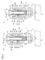
FIG. 2 is a cross sectional drawing of the optical fiber clamp of a first embodiment, whereinFIG. 2(a) shows a state where a pressure for pressing the optical fiber against a fiber placement pedestal by a clamper is set to be low, andFIG. 2(b) shows a state where the pressure for pressing the optical fiber against the fiber placement pedestal by the clamper is set to be high. -
FIG. 3 is a property graph showing changes in load by the optical fiber clamp ofFIG. 2 . -
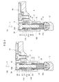
FIG. 4 is a cross sectional drawing of the optical fiber clamp of a second embodiment, whereinFIG. 4(a) shows a state where a pressure for pressing the optical fiber against a fiber placement pedestal by a clamper is set to be low, andFIG. 4(b) shows a state where the pressure for pressing the optical fiber against the fiber placement pedestal by the clamper is set to be high. -
FIG. 5 is a property graph showing changes in load by the optical fiber clamp ofFIG. 4 . - Exemplary embodiments of the present invention will be described hereinafter with reference to the appended drawings.
- First an optical fiber clamp and a method using the same will be described hereinafter with reference to
FIGs. 1 and2 . - The optical fiber clamp of the first embodiment is preferably applied to an optical fiber fusion splicer by which end faces of two optical fibers are fused and spliced. This is, for instance, applicable to a clamp mechanism for the optical fiber fusion splicer. This is applicable to ordinary optical fibers, polarization maintaining optical fibers, or optical fibers of any other types.
- The
optical fiber clamp 1 is, as shown inFIG. 1 , attached to aclamp elevation mechanism 8 provided in the optical fiber fusion splicer. Theclamp elevation mechanism 8 is so structured as to move up and down in a direction coming closer to and away from afiber positioning pedestal 11 shown inFIG. 2 . An arrow D inFIG. 1 shows a direction where theoptical fiber clamp 1 descends. - The
optical fiber clamp 1, as shown inFIG. 2 , has thefiber positioning pedestal 11 for setting anoptical fiber 10 in place, aclamper 12 for pressing downward and thereby fixing theoptical fiber 10 placed on thefiber positioning pedestal 11, and a pressure variation means for varying pressure to press theclamper 12 against theoptical fiber 10 against the opticalfiber positioning pedestal 11 in a graded way. - The
fiber positioning pedestal 11 is a pedestal formed in a unitary body having a V-notch in which theoptical fiber 10 is placed. Theclamper 12 has a tip with a flat face by which theoptical fiber 10 is pressed against thefiber positioning pedestal 11. - The pressure variation means is comprised of a
clamper supporting member 15, aspacer 16, aholder 17, acover 18, aguide pin 19, afirst spring 20 as an elastic member having a load area with high load disposed between theclamper supporting member 15 and thespacer 16, and asecond spring 21 as an elastic member having a load area with low load disposed in series with thefirst spring 20. - The
clamper supporting member 15 has theclamper 12 attached to its tip portion and is formed in a cylindrical shape having aflange portion 22 at its proximal end portion. At the tip portion of theclamper supporting member 15 formed is ashaft insertion hole 23 that horizontally penetrates the member. Theshaft insertion hole 23 is so structured that ashaft 24 attached to theclamper 12 is inserted into and passes through the hole. Theclamper 12 is thereby movably attached to the tip portion of theclamper supporting member 15 via theshaft 24. - In the
clamper supporting member 15 formed is a springhousing space portion 25 for housing thefirst spring 20 therein. One end of thefirst spring 20 is pressed against abottom face 25a of this springhousing space portion 25. - In the
flange portion 22 of theclamper supporting member 15 formed is acircular hole 26 which in its thickness direction penetrates the flange portion. - The
spacer 16 at its tip has adetent portion 27 as a stopper and at its proximal end portion has aroof portion 28. This is as a whole formed in a cylindrical shape like as an inverted bucket. Thedetent portion 27 passes through thecircular hole 26 formed in theflange portion 22 to be settled below theflange portion 22, and thereby latches on theflange portion 22 to prevent separation of thespacer 16 from theclamper supporting member 15. - Further the
spacer 16 is, as having aninternal periphery 16a of its tip portion in sliding contact with anexternal periphery 15a of theclamper supporting member 15, guided by theexternal periphery 15a to be slidable upward and downward relative to theclamper supporting member 15. - Further in the
spacer 16 formed is a springhousing space portion 29 for housing thefirst spring 20. The other end of thefirst spring 20 is pressed against aninternal face 28a of the roof portion of the springhousing space portion 29. - The
holder 17 is formed in a cylindrical shape having ahousing space portion 30 for at least housing thespacer 16 and the proximal portion of theclamper supporting member 15. In thishousing space portion 30 formed is astep portion 31 that receives theflange portion 22 of theclamper supporting member 15 to support theclamper supporting member 15. - The
cover 18 is attached to theholder 17 in such a way as to cover the upper portion of theholder 17. In thecover 18 formed is a springhousing space portion 34 for housing and placing thesecond spring 21 and theguide pin 19. Further in thecover 18 formed is a position regulatingscrew portion 36 into which ascrew portion 35 formed around the periphery of ahead portion 19A of theguide pin 19 is screwed so as to enable regulation of a position where theguide pin 19 is attached relative to thecover 18. - The
guide pin 19 has thehead portion 19A having thescrew portion 35 around its periphery and abody portion 19B forming a columnar shape. Theguide pin 19 is so formed that it is inserted into ahole portion 37 formed on a roof portiontop face 28b of thespacer 16 and then thebody portion 19B intrudes into the springhousing space portion 25 of theclamper supporting member 15. - The
first spring 20 is attached to the outer periphery of thebody portion 19B of theguide pin 19 and as well makes its both ends in contact with the bottominternal face 25a of this springhousing space portion 25 of theclamper supporting member 15 and theinternal face 28a of the roof portion of the springhousing space portion 29 respectively, thereby being disposed between theclamper supporting member 15 and thespacer 16. Thisfirst spring 20 is a compression coil spring with higher repulsive force having a load area of higher load than that of asecond spring 21 as described later as it is compressed in advance. - Further the
first spring 20 is disposed in a state of already being compressed between theclamper supporting member 15 and thespacer 16, and its degree of compression is made constant as thedetent portion 27 of thespacer 16 latches on theflange portion 22 of theclamper supporting member 15. - The
second spring 21 is attached to the outer periphery of thebody portion 19B of theguide pin 19 and as well makes its both ends in contact with thehead portion 19A of theguide pin 19 and thetop face 28b of thespacer 19 respectively, thereby being disposed therebetween. Thissecond spring 21 is, as being disposed in this way, disposed in series with thefirst spring 20. Thissecond spring 21 is a compression coil spring with lower repulsive force having a load area of lower load than that of thefirst spring 20. In other words, a relation W1 > W2 is established where the load by thefirst spring 20 is W1 and the lower load by thesecond spring 21 is W2. - Further the
second spring 21 is so structured as to be compressed by turning thehead portion 19A of theguide pin 19 by means of a drive or such to retract theguide pin 19. More specifically, thescrew portion 35 as a limiter device regulates the degree of compression of thesecond spring 21, consequently limits a deformation range of thesecond spring 21, and further makes an initial load applied to theoptical fiber 10 to be variable. - As the
first spring 20 and thesecond spring 21 respectively having distinct load areas from each other are arranged in series, the pressure variation means structured in a way as described above first puts thesecond spring 21 having a lower load area in action and next puts thefirst spring 20 having a higher load area in action, thereby changing pressure from low to high in a graded way. - To be more concrete, in the optical fiber clamp of the first embodiment, if a load F pressing the
cover 18 acts on the device in a state where theclamper 12 is in contact with theoptical fiber 10 placed on thefiber positioning pedestal 11, first thesecond spring 21 having the lower load area is compressed to give pressure by this lower load of thesecond spring 21 to theoptical fiber 10. This state is shown inFIG. 2(a) . When the degree of compression of thesecond spring 21 thereafter reaches its limit, thedetent portion 27 of thespacer 16 is released from theflange portion 22 of theclamper supporting member 15 and therefore thespacer 16 is pressed down so that thefirst spring 20 is compressed to give pressure by this higher load of thefirst spring 20 to theoptical fiber 10. In other words, clamping load by the lower load by thesecond spring 21 first acts on theoptical fiber 10 and clamping load by the higher load by thefirst spring 20 next acts on theoptical fiber 10. -
FIG. 3 shows change in clamping load. InFIG. 3 , the line L1 depicts change in clamping load when only one spring is used, and the line L2 depicts change in clamping load when two springs are used as in the optical fiber clamp of the first embodiment. In the optical fiber clamp of the first embodiment, by means of two springs, namely thefirst spring 20 and thesecond spring 21, arranged in series on a line, pressure applied to theoptical fiber 10 can be changed not in a linear way but in a graded way. Further, as the load by thesecond spring 21 is made lower than a load by only one spring, the device create an effect that it is avoided to place theoptical fiber 10 under relatively high pressure and therefore give a damage thereto. - As a structure in that two springs are arranged in series as in the optical fiber clamp of the first embodiment is used, clamping load can be drastically increased at a desired point that can be determined by controlling the degrees of compression of the
first spring 20 and thesecond spring 21 and these spring moduli. In particular the optical fiber clamp of the first embodiment, as thefirst spring 20 is provided with a degree of compression given in advance, realizes drastic load change (the part where the line L2 drastically leaps upward) when thefirst spring 20 starts acting. - Moreover, the optical fiber clamp of the first embodiment can produce high load even if a spring with a small spring modulus is used, and can exert steady load with small change in load even if the degree of compression is slightly changed.
- Further the optical fiber clamp of the first embodiment can change a target value of load to any degree by changing the spring moduli of the
first spring 20 and thesecond spring 21 and changing the degree of compression of thefirst spring 20. - Next, a method of clamping the
optical fiber 10 by using the optical fiber clamp of the first embodiment will be described hereinafter. - The
optical fiber clamp 1 is first moved just above theoptical fiber 10. As the whole of theoptical fiber clamp 1 is next moved down toward theoptical fiber 10 by means of theclamp elevation mechanism 8, theclamper 12 of theoptical fiber clamp 1 comes in contact with theoptical fiber 10. After theclamper 12 comes in contact with theoptical fiber 10, theholder 17, thecover 18, and theguide pin 19 commonly continues to go down. Thesecond spring 21 is consequently, as shown inFIG. 2(a) , compressed so that its pressure acts as a clamping load to press theoptical fiber 10 against thefiber placing pedestal 11. In this state, only the low load of thesecond spring 21 acts on theoptical fiber 10. - During the clamping load by the
second spring 21 acts on theoptical fiber 10, as thedetent portion 27 of thespacer 16 keeps latching on theflange portion 22 of theclamper supporting member 15, the load by thefirst spring 20 does not act on theoptical fiber 10. - Then, when the
second spring 21 is compressed to reach its limit, thedetent portion 27 of thespacer 16 is released from theflange 22. Thespacer 16, as theinternal periphery 16a of its tip portion is in slidable contact with theexternal periphery 15a of theclamper supporting member 15, slides downward relative to theclamper supporting member 15. Consequently, as shown inFIG. 2(b) , thefirst spring 20 is compressed by being pressed by thespacer 16, and the pressure by thefirst spring 20 in turn acts as a clamping load to press theoptical fiber 10 against thefiber placing pedestal 11. In this state, the degree of compression reaches its limit because each coil of thesecond spring 21 rests against its neighbor. Thus only the high load by thefirst spring 20 acts on theoptical fiber 10. - Consequently, according to two springs of the
first spring 20 and thesecond spring 21 having distinct load areas, thesecond spring 21 having the load area of the low load first comes into action and thefirst spring 20 having the load area of the high load next comes into action, so that the load on theclamper 12 changes in a graded way from the low load to the high load, when clamping theoptical fiber 10. - According to any of known clamps, at a time of being used to clamp an optical fiber, the optical fiber often gets out of a desired location or often twists. According to studies by the present inventors, this problem comes from a fact that an optimal load on a clamp varies depending on factors such as a diameter of the optical fiber. According to the first embodiment, as the
optical fiber 10 is clamped with changing the load on theclamp 12 from the low load to the high load in a graded way, dislocation and twisting hardly occur. In a case where optical fibers being different in diameter, or polarization maintaining optical fibers, are fused and spliced, the device and the method do not give damages to theoptical fiber 10 and do not cause dislocation. As being free from dislocation and twisting, it is enabled to suppress transmission loss at the spliced part. - According to the first embodiment, as it is so constituted that two of the
first spring 20 and thesecond spring 21 having distinct load areas are arranged in series so as to make thesecond spring 21 having a low load area to act and thefirst spring 20 having a high load area to act in this order, thereby changing the pressure from low to high in a graded way, it does not require other means such as an electromagnet or a rack-and-pinion mechanism, more specifically employs a simple structure, to clamp theoptical fiber 10 with greatly changing the clamping load. Thus, not only to an ordinary optical fiber but also to a polarization maintaining optical fibers, it applies an optimal clamping load in accordance with its diameter when clamping theoptical fiber 10. - Further according to the first embodiment, as it is so constituted that the
detent portion 27 of thespacer 16 is released from theflange portion 22, then thespacer 16 is pressed down so as to compress thefirst spring 20, and then the high load by thefirst spring 20 is applied to the subject, the simple structure by the release of lock of thespacer 16 enables changing the clamping load. - Further according to the first embodiment, as the
first spring 20 is so disposed as to have the degree of compression at the initial state, great change in load is realized when thefirst spring 20 starts to act. - Further according to the first embodiment, as the
second spring 21 is compressed by rotating thehead portion 19A of theguide pin 19 to press theguide pin 19 down, so as to enable change of the initial load applied to theoptical fiber 10, the initial load applied to theoptical fiber 10 can be freely changed in accordance with the diameter of theoptical fiber 10. - Next, the second embodiment will be described with reference to
FIG. 4 . In the second embodiment, detailed descriptions about components identical to those of the optical fiber clamp of the first embodiment will be omitted while the identical reference numerals are attached thereto. Descriptions will be given only about distinct components. - An optical fiber clamp of the second embodiment shares a common basic constitution with that of the first embodiment but differs from the first embodiment in that the
first spring 20 is not in advance compressed to some degree to bear a load and is thus made to produce great change in load when thefirst spring 20 starts to act. The optical fiber clamp of the second embodiment, on the basis of the structural differences, differs from the optical fiber clamp of the first embodiment in the following points. - The pressure variation means of the
optical fiber clamp 1 of the second embodiment is, as shown inFIG. 4 , comprised of aclamper supporting member 15, aholder 17, acover 18, aguide pin 19, aspacer 37 having distinct functions from that of the first embodiment, afirst spring 20 as an elastic member having a high load area disposed between theclamper supporting member 15 and thespacer 37, and asecond spring 21 as an elastic member having a low load area disposed in series with thefirst spring 20. - The
clamper supporting member 15 of the second embodiment is similar to that of the first embodiment in that theclamper 12 is attached to its tip portion and is formed to be a cylindrical shape having theflange portion 22 at its proximal end portion. Theclamper 12 is identical to that shown inFIG. 2 of the first embodiment whileFIG. 4 shows a view from a different viewpoint. Theclamper 12 ofFIG. 4 shows a section perpendicular to the section ofFIG. 2 . - The
holder 17 of the second embodiment has ahousing space portion 30 housing the proximal end portion of theclamper supporting member 15. In thehousing space portion 30 formed is astep portion 31 that receives theflange portion 22 of theclamper supporting member 15 to support theclamper supporting member 15. - In the
cover 18 formed is a springhousing space portion 34 for housing and placing thesecond spring 21 and theguide pin 19. Further in thecover 18 formed is a position regulatingscrew portion 36 into which ascrew portion 35 formed around the periphery of ahead portion 19A of theguide pin 19 is screwed so as to enable regulation of a position where theguide pin 19 is attached relative to thecover 18. - The
guide pin 19 has thehead portion 19A having thescrew portion 35 around its periphery and abody portion 19B forming a columnar shape. Thisguide pin 19 is so formed that thebody portion 19B intrudes into the springhousing space portion 25 of theclamper supporting member 15. Further theguide pin 19 has acircular slot 41 for making thehead portion 19A to house thesecond spring 21. - The
spacer 37 is formed in a ring shape distinct from that of the first embodiment. And, thespacer 37 is attached to the outer periphery of thebody portion 19B of theguide pin 19 and is also made movable upward and downward relative to thebody portion 19B. - The
first spring 20 of the second embodiment is attached to the outer periphery of thebody portion 19B of theguide pin 19, and further has its both ends in contact with abottom face 25a of the springhousing space portion 25 and alower face 37a of thespacer 37 respectively, thereby being disposed between theclamper supporting member 15 and thespacer 37. Thisfirst spring 20 is a compression coil spring with higher repulsive force having a load area of higher load than that of asecond spring 21 as described later. - The
second spring 21 of the second embodiment is attached to the outer periphery of thebody portion 19B of theguide pin 19, and further has its both ends in contact with thecircular slot 41 formed in thehead portion 19A of theguide pin 19 and anupper face 37b of thespacer 37 respectively, thereby being disposed therebetween. Thesecond spring 21, as being disposed in this way, arranged in series with thefirst spring 20. Thissecond spring 21 is a compression coils spring with lower repulsive force having a load area of lower load than that of thefirst spring 20. - Further the
second spring 21 is so structure as to be compressed by turning thehead portion 19A of theguide pin 19 to retract theguide pin 19 by means of a drive or such. Therefore thesecond spring 21 mainly makes an initial load applied to theoptical fiber 10 to be variable by turning theguide pin 19 to retract it. - As the
first spring 20 and thesecond spring 21 respectively having distinct load areas from each other are arranged in series, the pressure variation means structured in a way as described above first puts thesecond spring 21 having a lower load area in action and next puts thefirst spring 20 having a higher load area in action, thereby changing pressure from low to high in a graded way. - To be more concrete, in the optical fiber clamp of the second embodiment, if a load F pressing the
cover 18 acts on the device in a state where theclamper 12 is in contact with theoptical fiber 10 placed on thefiber positioning pedestal 11, first thesecond spring 21 having the lower load area is mainly compressed to give pressure by this lower load of thesecond spring 21 to theoptical fiber 10. This state is shown inFIG. 4(a) . When the degree of compression of thesecond spring 21 thereafter reaches its limit, thefirst spring 20 is next compressed to give pressure by this higher load of thefirst spring 20 to theoptical fiber 10. In other words, clamping load by the lower load by thesecond spring 21 first acts on theoptical fiber 10 and clamping load by the higher load by thefirst spring 20 next acts on theoptical fiber 10. -
FIG. 5 shows change in clamping load. The optical fiber clamp of the second embodiment, by using two of thefirst spring 20 and thesecond spring 21 arranged in line, can change pressure applied to theoptical fiber 10 not in a linear way but in such a way that the slope of the load change suddenly changes at a certain point. - As the optical fiber clamp of the second embodiment employs a structure in that two springs are arranged in series as with the first embodiment, clamping load can be drastically increased at a desired point that can be determined by controlling the degrees of compression of the
first spring 20 and thesecond spring 21 and these spring moduli. As being understood from the changes in clamping load ofFIG. 5 , when the sinking degree of the clamp (the degree of compression of the springs) is about 1 mm, the load stays to be about one fold, when the sinking degree of the clamp is 3 mm, the load becomes about five fold. By the optical fiber clamp of the second embodiment, while the stroke is the same, if thespacer 37 is disposed at a lower point, lower by 3 mm for example, the device can be manually changed into a mode of the high load area. - Meanwhile the optical fiber clamp of the second embodiment is so designed that it exerts one fold load when the
second spring 21 of the low load is in action and about five fold load when thefirst spring 20 of the high load is in action, at a time when the degree of compression is 3 mm. - Next, a method of clamping the
optical fiber 10 by using the optical fiber clamp of the second embodiment will be described hereinafter. - The
optical fiber clamp 1 is first moved just above theoptical fiber 10. As the whole of theoptical fiber clamp 1 is next moved down toward theoptical fiber 10 by means of theclamp elevation mechanism 8, theclamper 12 of theoptical fiber clamp 1 comes in contact with theoptical fiber 10. After theclamper 12 comes in contact with theoptical fiber 10, theholder 17, thecover 18, and theguide pin 19 commonly continues to go down. Thesecond spring 21 is consequently, as shown inFIG. 4(a) , compressed so that its pressure acts as a clamping load to press theoptical fiber 10 against thefiber placing pedestal 11. In this state, only the low load of thesecond spring 21 acts on theoptical fiber 10. - During the clamping load by the
second spring 21 acts on theoptical fiber 10, the load by thefirst spring 20 does not act on theoptical fiber 10. - Then, when the
second spring 21 is compressed to its limit, theholder 17, thecover 18 and theguide pin 19, as theclamper supporting member 15 functions as a guide, go down together. Consequently, as shown inFIG. 4(b) , thefirst spring 20 is compressed and the pressure by thefirst spring 20 in turn acts as a clamping load to press theoptical fiber 10 against thefiber placing pedestal 11. In this state, because each coil of thesecond spring 21 rests against its neighbor and the degree of compression reaches its limit, the high load by thefirst spring 20 acts on theoptical fiber 10. - Consequently, according to two springs of the
first spring 20 and thesecond spring 21 having distinct load areas, thesecond spring 21 having the load area of the low load first operates and thefirst spring 20 having the load area of the high load next operates, so that the load on theclamper 12 changes in a graded way from the low load to the high load, when clamping theoptical fiber 10. - According to the method of clamping an optical fiber of the second embodiment, as with the first embodiment, as the device is so structured as to make the
second spring 21 having a low load area to act and next thefirst spring 20 having a high load area to act in this order to clamp theoptical fiber 10, theoptical fiber 10 can be clamped without damaging theoptical fiber 10 and with preventing dislocation of theoptical fiber 10 when optical fibers having distinct diameters or polarization maintaining optical fibers are to be fused and spliced. Therefore, according to the second embodiment, it is enabled to suppress connection loss (transmission loss) of the splicedoptical fiber 10. - According to the second embodiment, as it is so constituted that two of the
first spring 20 and thesecond spring 21 having distinct load areas are arranged in series so as to make thesecond spring 21 having a low load area to come into action and thefirst spring 20 having a high load area to come into action in this order, thereby changing the pressure from low to high in a graded way, it does not require other means such as an electromagnet or a rack-and-pinion mechanism, more specifically employs a simple structure, to clamp theoptical fiber 10 with greatly changing the clamping load. Thus, not only to ordinary optical fibers but also to polarization maintaining optical fibers, it applies an optimal clamping load in accordance with its diameter when clamping theoptical fiber 10. - Further according to the second embodiment, as the
second spring 21 is compressed by rotating thehead portion 19A of theguide pin 19 to press theguide pin 19 down, thereby enabling change of the initial load applied to theoptical fiber 10, the initial load applied to theoptical fiber 10 can be freely changed in accordance with the diameter of theoptical fiber 10. - While, in any of the optical fiber clamps of the first and second embodiments, two springs are used and arranged in series, three or more springs may be arranged in order to control the clamping load with a plurality of grades.
- Further, as the
first spring 20 and thesecond spring 21 used in the first and second embodiments, irregular pitch springs or conical springs for example may be used. These springs change load in non-linear ways depending on the degree of compression and thus make the clamping load to be variable in a further wider range. - Further, while the
detent portion 27 as a stopper is formed on thespacer 16 and is made to latch on theflange portion 22 of theclamp supporting member 15 in the first embodiment, to the contrary, not shown in the drawings, it may be modified so that adetent portion 27 is formed on theclamp supporting member 15 and is made to latch on thespacer 16, thereby releasing thespacer 16 when thesecond spring 21 is compressed to the limit of its deformation range. - The present invention provides a device of setting an optical fiber precisely in place at a time of fusing and splicing end faces of two optical fibers.
Claims (5)
- A device for setting an optical fiber in place, comprising:a pedestal capable of supporting the optical fiber;a clamper having the optical fiber gripped between the clamper and the pedestal; anda pressure device having a first elastic member bearing a first load area, a second elastic member bearing a second load area distinct from the first load area, and a limiter device limiting a deformation range of the second elastic member, the pressure device being so linked with the clamper as to, in the deformation range, cause the second elastic member to pressurize the clamper, and, after reaching a limit of the deformation range, cause the first elastic member to pressurize the clamper.
- The device of claim 1,
wherein the pressure device comprises a support member configured to support the clamper, a spacer slidably fitting with the support member, and a stopper configured to temporarily fix the spacer with the support member;
wherein the first elastic member is interposed between the support member and the spacer to press the support member;
wherein the second elastic member is so disposed as to press the spacer; and
wherein the stopper is so engaged with the spacer or the support member as to release the spacer when the second elastic member is compressed to reach the limit of the deformation range. - The device of claim 2, wherein the first elastic member is compressed in advance.
- The device of claim 1, wherein the limiter device comprises a screw for regulating a degree of compression of the second elastic member.
- A method for setting an optical fiber in place, comprising:supporting the optical fiber on a pedestal;gripping the optical fiber between a clamper and the pedestal; andusing a pressure device having a first elastic member bearing a first load area, a second elastic member bearing a second load area distinct from the first load area, and a limiter device limiting a deformation range of the second elastic member, to, in the deformation range, cause the second elastic member to pressurize the clamper, and, after reaching a limit of the deformation range, cause the first elastic member to pressurize the clamper.
Applications Claiming Priority (1)
| Application Number | Priority Date | Filing Date | Title |
|---|---|---|---|
| PCT/JP2011/051250 WO2012101750A1 (en) | 2011-01-24 | 2011-01-24 | Optical fibre clamping device and optical fibre clamping method |
Publications (3)
| Publication Number | Publication Date |
|---|---|
| EP2589996A1 true EP2589996A1 (en) | 2013-05-08 |
| EP2589996A4 EP2589996A4 (en) | 2013-10-16 |
| EP2589996B1 EP2589996B1 (en) | 2016-01-20 |
Family
ID=46580360
Family Applications (1)
| Application Number | Title | Priority Date | Filing Date |
|---|---|---|---|
| EP11857100.9A Active EP2589996B1 (en) | 2011-01-24 | 2011-01-24 | Optical fibre clamping device and optical fibre clamping method |
Country Status (5)
| Country | Link |
|---|---|
| US (1) | US9122036B2 (en) |
| EP (1) | EP2589996B1 (en) |
| JP (1) | JP5259025B2 (en) |
| CN (1) | CN102959445A (en) |
| WO (1) | WO2012101750A1 (en) |
Families Citing this family (2)
| Publication number | Priority date | Publication date | Assignee | Title |
|---|---|---|---|---|
| JP5810461B2 (en) * | 2011-07-01 | 2015-11-11 | Seiオプティフロンティア株式会社 | Optical fiber fusion splicer |
| WO2022070485A1 (en) * | 2020-09-30 | 2022-04-07 | 株式会社フジクラ | Optical connector |
Family Cites Families (14)
| Publication number | Priority date | Publication date | Assignee | Title |
|---|---|---|---|---|
| JP2620331B2 (en) * | 1988-09-26 | 1997-06-11 | 住友電気工業株式会社 | Optical fiber clamp mechanism |
| JPH08201641A (en) | 1995-01-23 | 1996-08-09 | Furukawa Electric Co Ltd:The | Optical fiber clamp mechanism for fusion splicer |
| JP2000019339A (en) * | 1998-07-03 | 2000-01-21 | Furukawa Electric Co Ltd:The | Optical fiber clamp mechanism |
| JP3761192B2 (en) * | 1998-07-14 | 2006-03-29 | 古河電気工業株式会社 | Optical fiber clamp mechanism |
| JP2000241652A (en) | 1999-02-23 | 2000-09-08 | Fujikura Ltd | Fiber clamp method and mechanism for PM fiber fusion splicing |
| JP2002006167A (en) | 2000-06-19 | 2002-01-09 | Fujikura Ltd | Optical fiber fusion splicer |
| JP4750953B2 (en) * | 2001-02-14 | 2011-08-17 | 株式会社アマダ | Upper mold holder device |
| US6608958B2 (en) * | 2001-07-06 | 2003-08-19 | Ksaria Corporation | Centralizing clamp for an optical fiber |
| TW545365U (en) * | 2001-12-13 | 2003-08-01 | Ind Tech Res Inst | Handheld optical fiber cutting apparatus |
| JP2005321644A (en) * | 2004-05-10 | 2005-11-17 | Fujikura Ltd | Optical fiber reinforcement sleeve heating device |
| JP2007072080A (en) * | 2005-09-06 | 2007-03-22 | Fujikura Ltd | Optical fiber end holding device and method |
| US7512305B2 (en) * | 2006-02-08 | 2009-03-31 | Bookham Technology Plc | Precision optical fiber clamp |
| JP2008070704A (en) | 2006-09-15 | 2008-03-27 | Furukawa Electric Co Ltd:The | Fusion splicer and fusion splicing method |
| WO2011061805A1 (en) * | 2009-11-20 | 2011-05-26 | 富士通テレコムネットワークス株式会社 | Fiber clamp mechanism |
-
2011
- 2011-01-24 CN CN2011800317586A patent/CN102959445A/en active Pending
- 2011-01-24 WO PCT/JP2011/051250 patent/WO2012101750A1/en not_active Ceased
- 2011-01-24 JP JP2012554526A patent/JP5259025B2/en active Active
- 2011-01-24 EP EP11857100.9A patent/EP2589996B1/en active Active
-
2013
- 2013-01-17 US US13/744,010 patent/US9122036B2/en active Active
Also Published As
| Publication number | Publication date |
|---|---|
| US20130129301A1 (en) | 2013-05-23 |
| WO2012101750A1 (en) | 2012-08-02 |
| CN102959445A (en) | 2013-03-06 |
| EP2589996A4 (en) | 2013-10-16 |
| EP2589996B1 (en) | 2016-01-20 |
| JP5259025B2 (en) | 2013-08-07 |
| US9122036B2 (en) | 2015-09-01 |
| JPWO2012101750A1 (en) | 2014-06-30 |
Similar Documents
| Publication | Publication Date | Title |
|---|---|---|
| US8196793B2 (en) | Optical fiber cutting apparatus and optical fiber cutting method | |
| DE68923034T2 (en) | Precision punched centering element for an optical fiber connection. | |
| RU2577388C2 (en) | Optical connector with splice element to terminate cable with protective shell in place of operation | |
| RU2625250C2 (en) | Optical connector for cables with outer sheath | |
| RU2350988C2 (en) | Device for seizure and splicing of optic fibers | |
| US7226215B2 (en) | Optical fiber connector | |
| JP2006133780A (en) | Reconnectable LC connector assembly and cam end treatment tool | |
| CN112083531B (en) | Optical fiber movable connector | |
| EP2589996B1 (en) | Optical fibre clamping device and optical fibre clamping method | |
| US7787740B2 (en) | Universal cable bracket | |
| US8826517B2 (en) | Fiber handler having multiple sides | |
| US5013123A (en) | Stamped precision lightguide interconnect centering element | |
| CN102918298B (en) | Method and arrangement in arranging an aluminum ferrule to a high strength eve of a steel wire | |
| US11121517B2 (en) | Core wire deformation jig and core wire deformation method | |
| US10746927B2 (en) | Optical-fiber-holding member, and fusing device | |
| US5005940A (en) | Connector for optical fibers and the like | |
| JP2000241652A (en) | Fiber clamp method and mechanism for PM fiber fusion splicing | |
| CN211236332U (en) | Cutting device fitting for special optical fiber and cutting device | |
| US11886012B2 (en) | Optical fiber lateral input/output device | |
| US20130223808A1 (en) | Cable clamp assembly and method for a flat fiber optic cable | |
| JP2000019339A (en) | Optical fiber clamp mechanism | |
| CN218788103U (en) | Clamp positioning block of optical fiber fusion splicer | |
| JP2000019338A (en) | Optical fiber clamp mechanism | |
| CN110941047B (en) | Cleaving an optical fiber | |
| EP2743745A1 (en) | Field-installable optical splice |
Legal Events
| Date | Code | Title | Description |
|---|---|---|---|
| PUAI | Public reference made under article 153(3) epc to a published international application that has entered the european phase |
Free format text: ORIGINAL CODE: 0009012 |
|
| 17P | Request for examination filed |
Effective date: 20130131 |
|
| AK | Designated contracting states |
Kind code of ref document: A1 Designated state(s): AL AT BE BG CH CY CZ DE DK EE ES FI FR GB GR HR HU IE IS IT LI LT LU LV MC MK MT NL NO PL PT RO RS SE SI SK SM TR |
|
| RIC1 | Information provided on ipc code assigned before grant |
Ipc: G02B 6/255 20060101AFI20130905BHEP |
|
| A4 | Supplementary search report drawn up and despatched |
Effective date: 20130913 |
|
| DAX | Request for extension of the european patent (deleted) | ||
| 17Q | First examination report despatched |
Effective date: 20140505 |
|
| 17Q | First examination report despatched |
Effective date: 20140530 |
|
| GRAP | Despatch of communication of intention to grant a patent |
Free format text: ORIGINAL CODE: EPIDOSNIGR1 |
|
| INTG | Intention to grant announced |
Effective date: 20150909 |
|
| GRAS | Grant fee paid |
Free format text: ORIGINAL CODE: EPIDOSNIGR3 |
|
| GRAA | (expected) grant |
Free format text: ORIGINAL CODE: 0009210 |
|
| AK | Designated contracting states |
Kind code of ref document: B1 Designated state(s): AL AT BE BG CH CY CZ DE DK EE ES FI FR GB GR HR HU IE IS IT LI LT LU LV MC MK MT NL NO PL PT RO RS SE SI SK SM TR |
|
| REG | Reference to a national code |
Ref country code: GB Ref legal event code: FG4D |
|
| REG | Reference to a national code |
Ref country code: FR Ref legal event code: PLFP Year of fee payment: 6 |
|
| REG | Reference to a national code |
Ref country code: CH Ref legal event code: EP |
|
| REG | Reference to a national code |
Ref country code: IE Ref legal event code: FG4D |
|
| REG | Reference to a national code |
Ref country code: AT Ref legal event code: REF Ref document number: 771994 Country of ref document: AT Kind code of ref document: T Effective date: 20160215 |
|
| REG | Reference to a national code |
Ref country code: DE Ref legal event code: R096 Ref document number: 602011022911 Country of ref document: DE |
|
| REG | Reference to a national code |
Ref country code: LT Ref legal event code: MG4D Ref country code: NL Ref legal event code: MP Effective date: 20160120 |
|
| PG25 | Lapsed in a contracting state [announced via postgrant information from national office to epo] |
Ref country code: BE Free format text: LAPSE BECAUSE OF NON-PAYMENT OF DUE FEES Effective date: 20160131 |
|
| REG | Reference to a national code |
Ref country code: AT Ref legal event code: MK05 Ref document number: 771994 Country of ref document: AT Kind code of ref document: T Effective date: 20160120 |
|
| PG25 | Lapsed in a contracting state [announced via postgrant information from national office to epo] |
Ref country code: NL Free format text: LAPSE BECAUSE OF FAILURE TO SUBMIT A TRANSLATION OF THE DESCRIPTION OR TO PAY THE FEE WITHIN THE PRESCRIBED TIME-LIMIT Effective date: 20160120 |
|
| PG25 | Lapsed in a contracting state [announced via postgrant information from national office to epo] |
Ref country code: IT Free format text: LAPSE BECAUSE OF FAILURE TO SUBMIT A TRANSLATION OF THE DESCRIPTION OR TO PAY THE FEE WITHIN THE PRESCRIBED TIME-LIMIT Effective date: 20160120 Ref country code: NO Free format text: LAPSE BECAUSE OF FAILURE TO SUBMIT A TRANSLATION OF THE DESCRIPTION OR TO PAY THE FEE WITHIN THE PRESCRIBED TIME-LIMIT Effective date: 20160420 Ref country code: FI Free format text: LAPSE BECAUSE OF FAILURE TO SUBMIT A TRANSLATION OF THE DESCRIPTION OR TO PAY THE FEE WITHIN THE PRESCRIBED TIME-LIMIT Effective date: 20160120 Ref country code: HR Free format text: LAPSE BECAUSE OF FAILURE TO SUBMIT A TRANSLATION OF THE DESCRIPTION OR TO PAY THE FEE WITHIN THE PRESCRIBED TIME-LIMIT Effective date: 20160120 Ref country code: GR Free format text: LAPSE BECAUSE OF FAILURE TO SUBMIT A TRANSLATION OF THE DESCRIPTION OR TO PAY THE FEE WITHIN THE PRESCRIBED TIME-LIMIT Effective date: 20160421 Ref country code: ES Free format text: LAPSE BECAUSE OF FAILURE TO SUBMIT A TRANSLATION OF THE DESCRIPTION OR TO PAY THE FEE WITHIN THE PRESCRIBED TIME-LIMIT Effective date: 20160120 |
|
| PG25 | Lapsed in a contracting state [announced via postgrant information from national office to epo] |
Ref country code: LT Free format text: LAPSE BECAUSE OF FAILURE TO SUBMIT A TRANSLATION OF THE DESCRIPTION OR TO PAY THE FEE WITHIN THE PRESCRIBED TIME-LIMIT Effective date: 20160120 Ref country code: PL Free format text: LAPSE BECAUSE OF FAILURE TO SUBMIT A TRANSLATION OF THE DESCRIPTION OR TO PAY THE FEE WITHIN THE PRESCRIBED TIME-LIMIT Effective date: 20160120 Ref country code: IS Free format text: LAPSE BECAUSE OF FAILURE TO SUBMIT A TRANSLATION OF THE DESCRIPTION OR TO PAY THE FEE WITHIN THE PRESCRIBED TIME-LIMIT Effective date: 20160520 Ref country code: SE Free format text: LAPSE BECAUSE OF FAILURE TO SUBMIT A TRANSLATION OF THE DESCRIPTION OR TO PAY THE FEE WITHIN THE PRESCRIBED TIME-LIMIT Effective date: 20160120 Ref country code: LV Free format text: LAPSE BECAUSE OF FAILURE TO SUBMIT A TRANSLATION OF THE DESCRIPTION OR TO PAY THE FEE WITHIN THE PRESCRIBED TIME-LIMIT Effective date: 20160120 Ref country code: PT Free format text: LAPSE BECAUSE OF FAILURE TO SUBMIT A TRANSLATION OF THE DESCRIPTION OR TO PAY THE FEE WITHIN THE PRESCRIBED TIME-LIMIT Effective date: 20160520 Ref country code: AT Free format text: LAPSE BECAUSE OF FAILURE TO SUBMIT A TRANSLATION OF THE DESCRIPTION OR TO PAY THE FEE WITHIN THE PRESCRIBED TIME-LIMIT Effective date: 20160120 Ref country code: RS Free format text: LAPSE BECAUSE OF FAILURE TO SUBMIT A TRANSLATION OF THE DESCRIPTION OR TO PAY THE FEE WITHIN THE PRESCRIBED TIME-LIMIT Effective date: 20160120 |
|
| REG | Reference to a national code |
Ref country code: CH Ref legal event code: PL |
|
| REG | Reference to a national code |
Ref country code: DE Ref legal event code: R097 Ref document number: 602011022911 Country of ref document: DE |
|
| PG25 | Lapsed in a contracting state [announced via postgrant information from national office to epo] |
Ref country code: MC Free format text: LAPSE BECAUSE OF FAILURE TO SUBMIT A TRANSLATION OF THE DESCRIPTION OR TO PAY THE FEE WITHIN THE PRESCRIBED TIME-LIMIT Effective date: 20160120 Ref country code: EE Free format text: LAPSE BECAUSE OF FAILURE TO SUBMIT A TRANSLATION OF THE DESCRIPTION OR TO PAY THE FEE WITHIN THE PRESCRIBED TIME-LIMIT Effective date: 20160120 Ref country code: DK Free format text: LAPSE BECAUSE OF FAILURE TO SUBMIT A TRANSLATION OF THE DESCRIPTION OR TO PAY THE FEE WITHIN THE PRESCRIBED TIME-LIMIT Effective date: 20160120 Ref country code: CH Free format text: LAPSE BECAUSE OF NON-PAYMENT OF DUE FEES Effective date: 20160131 Ref country code: LI Free format text: LAPSE BECAUSE OF NON-PAYMENT OF DUE FEES Effective date: 20160131 |
|
| REG | Reference to a national code |
Ref country code: IE Ref legal event code: MM4A |
|
| PLBE | No opposition filed within time limit |
Free format text: ORIGINAL CODE: 0009261 |
|
| STAA | Information on the status of an ep patent application or granted ep patent |
Free format text: STATUS: NO OPPOSITION FILED WITHIN TIME LIMIT |
|
| PG25 | Lapsed in a contracting state [announced via postgrant information from national office to epo] |
Ref country code: CZ Free format text: LAPSE BECAUSE OF FAILURE TO SUBMIT A TRANSLATION OF THE DESCRIPTION OR TO PAY THE FEE WITHIN THE PRESCRIBED TIME-LIMIT Effective date: 20160120 Ref country code: RO Free format text: LAPSE BECAUSE OF FAILURE TO SUBMIT A TRANSLATION OF THE DESCRIPTION OR TO PAY THE FEE WITHIN THE PRESCRIBED TIME-LIMIT Effective date: 20160120 Ref country code: SK Free format text: LAPSE BECAUSE OF FAILURE TO SUBMIT A TRANSLATION OF THE DESCRIPTION OR TO PAY THE FEE WITHIN THE PRESCRIBED TIME-LIMIT Effective date: 20160120 Ref country code: SM Free format text: LAPSE BECAUSE OF FAILURE TO SUBMIT A TRANSLATION OF THE DESCRIPTION OR TO PAY THE FEE WITHIN THE PRESCRIBED TIME-LIMIT Effective date: 20160120 |
|
| REG | Reference to a national code |
Ref country code: FR Ref legal event code: PLFP Year of fee payment: 7 |
|
| 26N | No opposition filed |
Effective date: 20161021 |
|
| PG25 | Lapsed in a contracting state [announced via postgrant information from national office to epo] |
Ref country code: BE Free format text: LAPSE BECAUSE OF FAILURE TO SUBMIT A TRANSLATION OF THE DESCRIPTION OR TO PAY THE FEE WITHIN THE PRESCRIBED TIME-LIMIT Effective date: 20160120 |
|
| PG25 | Lapsed in a contracting state [announced via postgrant information from national office to epo] |
Ref country code: IE Free format text: LAPSE BECAUSE OF NON-PAYMENT OF DUE FEES Effective date: 20160124 |
|
| PG25 | Lapsed in a contracting state [announced via postgrant information from national office to epo] |
Ref country code: SI Free format text: LAPSE BECAUSE OF FAILURE TO SUBMIT A TRANSLATION OF THE DESCRIPTION OR TO PAY THE FEE WITHIN THE PRESCRIBED TIME-LIMIT Effective date: 20160120 Ref country code: BG Free format text: LAPSE BECAUSE OF FAILURE TO SUBMIT A TRANSLATION OF THE DESCRIPTION OR TO PAY THE FEE WITHIN THE PRESCRIBED TIME-LIMIT Effective date: 20160420 |
|
| PG25 | Lapsed in a contracting state [announced via postgrant information from national office to epo] |
Ref country code: MT Free format text: LAPSE BECAUSE OF FAILURE TO SUBMIT A TRANSLATION OF THE DESCRIPTION OR TO PAY THE FEE WITHIN THE PRESCRIBED TIME-LIMIT Effective date: 20160120 |
|
| REG | Reference to a national code |
Ref country code: FR Ref legal event code: PLFP Year of fee payment: 8 |
|
| PG25 | Lapsed in a contracting state [announced via postgrant information from national office to epo] |
Ref country code: CY Free format text: LAPSE BECAUSE OF FAILURE TO SUBMIT A TRANSLATION OF THE DESCRIPTION OR TO PAY THE FEE WITHIN THE PRESCRIBED TIME-LIMIT Effective date: 20160120 Ref country code: HU Free format text: LAPSE BECAUSE OF FAILURE TO SUBMIT A TRANSLATION OF THE DESCRIPTION OR TO PAY THE FEE WITHIN THE PRESCRIBED TIME-LIMIT; INVALID AB INITIO Effective date: 20110124 |
|
| PG25 | Lapsed in a contracting state [announced via postgrant information from national office to epo] |
Ref country code: MT Free format text: LAPSE BECAUSE OF FAILURE TO SUBMIT A TRANSLATION OF THE DESCRIPTION OR TO PAY THE FEE WITHIN THE PRESCRIBED TIME-LIMIT Effective date: 20160131 Ref country code: MK Free format text: LAPSE BECAUSE OF FAILURE TO SUBMIT A TRANSLATION OF THE DESCRIPTION OR TO PAY THE FEE WITHIN THE PRESCRIBED TIME-LIMIT Effective date: 20160120 Ref country code: LU Free format text: LAPSE BECAUSE OF NON-PAYMENT OF DUE FEES Effective date: 20160124 Ref country code: TR Free format text: LAPSE BECAUSE OF FAILURE TO SUBMIT A TRANSLATION OF THE DESCRIPTION OR TO PAY THE FEE WITHIN THE PRESCRIBED TIME-LIMIT Effective date: 20160120 |
|
| PG25 | Lapsed in a contracting state [announced via postgrant information from national office to epo] |
Ref country code: AL Free format text: LAPSE BECAUSE OF FAILURE TO SUBMIT A TRANSLATION OF THE DESCRIPTION OR TO PAY THE FEE WITHIN THE PRESCRIBED TIME-LIMIT Effective date: 20160120 |
|
| P01 | Opt-out of the competence of the unified patent court (upc) registered |
Effective date: 20230512 |
|
| PGFP | Annual fee paid to national office [announced via postgrant information from national office to epo] |
Ref country code: GB Payment date: 20251204 Year of fee payment: 16 |
|
| PGFP | Annual fee paid to national office [announced via postgrant information from national office to epo] |
Ref country code: FR Payment date: 20251128 Year of fee payment: 16 |
|
| PGFP | Annual fee paid to national office [announced via postgrant information from national office to epo] |
Ref country code: DE Payment date: 20251203 Year of fee payment: 16 |