EP2589836A1 - Travel control apparatus for working vehicle - Google Patents
Travel control apparatus for working vehicle Download PDFInfo
- Publication number
- EP2589836A1 EP2589836A1 EP11821407.1A EP11821407A EP2589836A1 EP 2589836 A1 EP2589836 A1 EP 2589836A1 EP 11821407 A EP11821407 A EP 11821407A EP 2589836 A1 EP2589836 A1 EP 2589836A1
- Authority
- EP
- European Patent Office
- Prior art keywords
- transmission
- gear ratio
- motor
- transmission gear
- displacement angle
- Prior art date
- Legal status (The legal status is an assumption and is not a legal conclusion. Google has not performed a legal analysis and makes no representation as to the accuracy of the status listed.)
- Withdrawn
Links
- 238000006073 displacement reaction Methods 0.000 claims abstract description 81
- 230000005540 biological transmission Effects 0.000 claims abstract description 70
- 230000035939 shock Effects 0.000 description 12
- 238000010586 diagram Methods 0.000 description 7
- 230000007704 transition Effects 0.000 description 5
- 230000007423 decrease Effects 0.000 description 4
- 230000008859 change Effects 0.000 description 3
- 239000000446 fuel Substances 0.000 description 2
- 238000004519 manufacturing process Methods 0.000 description 2
- 238000000034 method Methods 0.000 description 2
- 230000007935 neutral effect Effects 0.000 description 2
- 230000008569 process Effects 0.000 description 2
- 230000005856 abnormality Effects 0.000 description 1
- 230000008602 contraction Effects 0.000 description 1
- 230000000694 effects Effects 0.000 description 1
- 230000007246 mechanism Effects 0.000 description 1
- 230000002093 peripheral effect Effects 0.000 description 1
- 230000009467 reduction Effects 0.000 description 1
Images


Classifications
-
- F—MECHANICAL ENGINEERING; LIGHTING; HEATING; WEAPONS; BLASTING
- F16—ENGINEERING ELEMENTS AND UNITS; GENERAL MEASURES FOR PRODUCING AND MAINTAINING EFFECTIVE FUNCTIONING OF MACHINES OR INSTALLATIONS; THERMAL INSULATION IN GENERAL
- F16H—GEARING
- F16H61/00—Control functions within control units of change-speed- or reversing-gearings for conveying rotary motion ; Control of exclusively fluid gearing, friction gearing, gearings with endless flexible members or other particular types of gearing
- F16H61/02—Control functions within control units of change-speed- or reversing-gearings for conveying rotary motion ; Control of exclusively fluid gearing, friction gearing, gearings with endless flexible members or other particular types of gearing characterised by the signals used
-
- E—FIXED CONSTRUCTIONS
- E02—HYDRAULIC ENGINEERING; FOUNDATIONS; SOIL SHIFTING
- E02F—DREDGING; SOIL-SHIFTING
- E02F9/00—Component parts of dredgers or soil-shifting machines, not restricted to one of the kinds covered by groups E02F3/00 - E02F7/00
- E02F9/20—Drives; Control devices
- E02F9/2058—Electric or electro-mechanical or mechanical control devices of vehicle sub-units
- E02F9/2079—Control of mechanical transmission
-
- E—FIXED CONSTRUCTIONS
- E02—HYDRAULIC ENGINEERING; FOUNDATIONS; SOIL SHIFTING
- E02F—DREDGING; SOIL-SHIFTING
- E02F3/00—Dredgers; Soil-shifting machines
- E02F3/04—Dredgers; Soil-shifting machines mechanically-driven
- E02F3/28—Dredgers; Soil-shifting machines mechanically-driven with digging tools mounted on a dipper- or bucket-arm, i.e. there is either one arm or a pair of arms, e.g. dippers, buckets
- E02F3/283—Dredgers; Soil-shifting machines mechanically-driven with digging tools mounted on a dipper- or bucket-arm, i.e. there is either one arm or a pair of arms, e.g. dippers, buckets with a single arm pivoted directly on the chassis
-
- E—FIXED CONSTRUCTIONS
- E02—HYDRAULIC ENGINEERING; FOUNDATIONS; SOIL SHIFTING
- E02F—DREDGING; SOIL-SHIFTING
- E02F9/00—Component parts of dredgers or soil-shifting machines, not restricted to one of the kinds covered by groups E02F3/00 - E02F7/00
- E02F9/20—Drives; Control devices
- E02F9/202—Mechanical transmission, e.g. clutches, gears
-
- E—FIXED CONSTRUCTIONS
- E02—HYDRAULIC ENGINEERING; FOUNDATIONS; SOIL SHIFTING
- E02F—DREDGING; SOIL-SHIFTING
- E02F9/00—Component parts of dredgers or soil-shifting machines, not restricted to one of the kinds covered by groups E02F3/00 - E02F7/00
- E02F9/20—Drives; Control devices
- E02F9/22—Hydraulic or pneumatic drives
-
- E—FIXED CONSTRUCTIONS
- E02—HYDRAULIC ENGINEERING; FOUNDATIONS; SOIL SHIFTING
- E02F—DREDGING; SOIL-SHIFTING
- E02F9/00—Component parts of dredgers or soil-shifting machines, not restricted to one of the kinds covered by groups E02F3/00 - E02F7/00
- E02F9/20—Drives; Control devices
- E02F9/22—Hydraulic or pneumatic drives
- E02F9/2221—Control of flow rate; Load sensing arrangements
- E02F9/2232—Control of flow rate; Load sensing arrangements using one or more variable displacement pumps
- E02F9/2235—Control of flow rate; Load sensing arrangements using one or more variable displacement pumps including an electronic controller
-
- E—FIXED CONSTRUCTIONS
- E02—HYDRAULIC ENGINEERING; FOUNDATIONS; SOIL SHIFTING
- E02F—DREDGING; SOIL-SHIFTING
- E02F9/00—Component parts of dredgers or soil-shifting machines, not restricted to one of the kinds covered by groups E02F3/00 - E02F7/00
- E02F9/20—Drives; Control devices
- E02F9/22—Hydraulic or pneumatic drives
- E02F9/2253—Controlling the travelling speed of vehicles, e.g. adjusting travelling speed according to implement loads, control of hydrostatic transmission
-
- E—FIXED CONSTRUCTIONS
- E02—HYDRAULIC ENGINEERING; FOUNDATIONS; SOIL SHIFTING
- E02F—DREDGING; SOIL-SHIFTING
- E02F9/00—Component parts of dredgers or soil-shifting machines, not restricted to one of the kinds covered by groups E02F3/00 - E02F7/00
- E02F9/20—Drives; Control devices
- E02F9/22—Hydraulic or pneumatic drives
- E02F9/2278—Hydraulic circuits
- E02F9/2289—Closed circuit
-
- E—FIXED CONSTRUCTIONS
- E02—HYDRAULIC ENGINEERING; FOUNDATIONS; SOIL SHIFTING
- E02F—DREDGING; SOIL-SHIFTING
- E02F9/00—Component parts of dredgers or soil-shifting machines, not restricted to one of the kinds covered by groups E02F3/00 - E02F7/00
- E02F9/20—Drives; Control devices
- E02F9/22—Hydraulic or pneumatic drives
- E02F9/2278—Hydraulic circuits
- E02F9/2296—Systems with a variable displacement pump
-
- F—MECHANICAL ENGINEERING; LIGHTING; HEATING; WEAPONS; BLASTING
- F16—ENGINEERING ELEMENTS AND UNITS; GENERAL MEASURES FOR PRODUCING AND MAINTAINING EFFECTIVE FUNCTIONING OF MACHINES OR INSTALLATIONS; THERMAL INSULATION IN GENERAL
- F16H—GEARING
- F16H47/00—Combinations of mechanical gearing with fluid clutches or fluid gearing
-
- F—MECHANICAL ENGINEERING; LIGHTING; HEATING; WEAPONS; BLASTING
- F16—ENGINEERING ELEMENTS AND UNITS; GENERAL MEASURES FOR PRODUCING AND MAINTAINING EFFECTIVE FUNCTIONING OF MACHINES OR INSTALLATIONS; THERMAL INSULATION IN GENERAL
- F16H—GEARING
- F16H47/00—Combinations of mechanical gearing with fluid clutches or fluid gearing
- F16H47/02—Combinations of mechanical gearing with fluid clutches or fluid gearing the fluid gearing being of the volumetric type
-
- F—MECHANICAL ENGINEERING; LIGHTING; HEATING; WEAPONS; BLASTING
- F16—ENGINEERING ELEMENTS AND UNITS; GENERAL MEASURES FOR PRODUCING AND MAINTAINING EFFECTIVE FUNCTIONING OF MACHINES OR INSTALLATIONS; THERMAL INSULATION IN GENERAL
- F16H—GEARING
- F16H61/00—Control functions within control units of change-speed- or reversing-gearings for conveying rotary motion ; Control of exclusively fluid gearing, friction gearing, gearings with endless flexible members or other particular types of gearing
-
- F—MECHANICAL ENGINEERING; LIGHTING; HEATING; WEAPONS; BLASTING
- F16—ENGINEERING ELEMENTS AND UNITS; GENERAL MEASURES FOR PRODUCING AND MAINTAINING EFFECTIVE FUNCTIONING OF MACHINES OR INSTALLATIONS; THERMAL INSULATION IN GENERAL
- F16H—GEARING
- F16H61/00—Control functions within control units of change-speed- or reversing-gearings for conveying rotary motion ; Control of exclusively fluid gearing, friction gearing, gearings with endless flexible members or other particular types of gearing
- F16H61/38—Control of exclusively fluid gearing
- F16H61/40—Control of exclusively fluid gearing hydrostatic
- F16H61/4148—Open loop circuits
-
- F—MECHANICAL ENGINEERING; LIGHTING; HEATING; WEAPONS; BLASTING
- F16—ENGINEERING ELEMENTS AND UNITS; GENERAL MEASURES FOR PRODUCING AND MAINTAINING EFFECTIVE FUNCTIONING OF MACHINES OR INSTALLATIONS; THERMAL INSULATION IN GENERAL
- F16H—GEARING
- F16H61/00—Control functions within control units of change-speed- or reversing-gearings for conveying rotary motion ; Control of exclusively fluid gearing, friction gearing, gearings with endless flexible members or other particular types of gearing
- F16H61/38—Control of exclusively fluid gearing
- F16H61/40—Control of exclusively fluid gearing hydrostatic
- F16H61/42—Control of exclusively fluid gearing hydrostatic involving adjustment of a pump or motor with adjustable output or capacity
- F16H61/421—Motor capacity control by electro-hydraulic control means, e.g. using solenoid valves
-
- F—MECHANICAL ENGINEERING; LIGHTING; HEATING; WEAPONS; BLASTING
- F16—ENGINEERING ELEMENTS AND UNITS; GENERAL MEASURES FOR PRODUCING AND MAINTAINING EFFECTIVE FUNCTIONING OF MACHINES OR INSTALLATIONS; THERMAL INSULATION IN GENERAL
- F16H—GEARING
- F16H61/00—Control functions within control units of change-speed- or reversing-gearings for conveying rotary motion ; Control of exclusively fluid gearing, friction gearing, gearings with endless flexible members or other particular types of gearing
- F16H61/38—Control of exclusively fluid gearing
- F16H61/40—Control of exclusively fluid gearing hydrostatic
- F16H61/46—Automatic regulation in accordance with output requirements
- F16H61/462—Automatic regulation in accordance with output requirements for achieving a target speed ratio
-
- F—MECHANICAL ENGINEERING; LIGHTING; HEATING; WEAPONS; BLASTING
- F16—ENGINEERING ELEMENTS AND UNITS; GENERAL MEASURES FOR PRODUCING AND MAINTAINING EFFECTIVE FUNCTIONING OF MACHINES OR INSTALLATIONS; THERMAL INSULATION IN GENERAL
- F16H—GEARING
- F16H61/00—Control functions within control units of change-speed- or reversing-gearings for conveying rotary motion ; Control of exclusively fluid gearing, friction gearing, gearings with endless flexible members or other particular types of gearing
- F16H61/70—Control functions within control units of change-speed- or reversing-gearings for conveying rotary motion ; Control of exclusively fluid gearing, friction gearing, gearings with endless flexible members or other particular types of gearing specially adapted for change-speed gearing in group arrangement, i.e. with separate change-speed gear trains arranged in series, e.g. range or overdrive-type gearing arrangements
- F16H61/702—Control functions within control units of change-speed- or reversing-gearings for conveying rotary motion ; Control of exclusively fluid gearing, friction gearing, gearings with endless flexible members or other particular types of gearing specially adapted for change-speed gearing in group arrangement, i.e. with separate change-speed gear trains arranged in series, e.g. range or overdrive-type gearing arrangements using electric or electrohydraulic control means
Definitions
- the present invention relates to a travel control apparatus of a working vehicle such as a wheel loader.
- Patent Literature 1 There is a conventionally known working vehicle travel control apparatus that includes a transmission using a clutch that can be controlled only into a state of full engagement or a state of full disengagement, in which occurrence of a shock from when the disengaged clutch is engaged again is reduced (refer to Patent Literature 1). More specifically, occurrence of a gear shift shock when the clutch is engaged again is reduced by controlling the displacement angle of a hydraulic pump and matching the number of rotation between a power upstream-side with a power downstream-side of the clutch.
- Patent Literature 1 Japanese Laid-Open Patent Publication No. 2002-139148
- Patent Literature 1 described above is configured to reduce a gear shift shock by matching the number of rotation between a power upstream-side with a power downstream-side of the clutch, and hence a synchronization mechanism for matching the number of rotation is required.
- a working vehicle travel control apparatus comprising: a variable displacement hydraulic pump that is driven by an engine; a variable displacement hydraulic motor that is connected in a closed circuit to the hydraulic pump and driven upon pressure oil from the hydraulic pump; a first control unit that controls a motor displacement angle of the hydraulic motor by an electrical signal; a constant mesh transmission that includes a clutch device that includes a High clutch section that transmits power at a first transmission gear ratio and a Low clutch section that transmits power at a second transmission gear ratio, which is greater than the first transmission gear ratio, the constant mesh transmission that transmits or interrupts power from the hydraulic motor; and a second control unit that controls the first control unit so as to reduce the motor displacement angle to a predetermined value when the transmission is switched from the first transmission gear ratio to the second transmission gear ratio.
- the predetermined value of the motor displacement angle is set to be greater than a minimum displacement angle of the hydraulic motor and a minimal motor displacement angle at which the working vehicle can be driven by the hydraulic motor.
- the second control unit controls the first control unit so that when the transmission is switched from the first transmission gear ratio to the second transmission gear ratio, after the motor displacement angle is reduced to the predetermined value and fixed to the predetermined value for a predetermined period of time, and then the motor displacement angle is recovered.
- a wheel loader comprising a travel control apparatus according to any one of the first to third aspect.
- a gear shift shock can be reduced at the time of switching from High to Low.
- a working vehicle travel control apparatus according to an embodiment of the present invention will now be explained with reference to FIG. 1 to FIG. 5 .
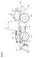
- FIG. 1 is a side view of a wheel loader that is an example of a working vehicle to which the travel control apparatus according to the present embodiment is applied.
- a wheel loader 100 is constituted with a front body 110 that includes an arm 111, a bucket 112, tires 113, etc., and a rear body 120 that includes a driver's cabin 121, an engine bay 122, tires 123, etc.
- the arm 111 vertically rotates (moves up and down) on actuation of an arm cylinder 114 and the bucket 112 vertically rotates (dumps or crowds) on actuation of a bucket cylinder 115.
- the front body 110 and the rear body 120 are rotatably connected with each other through a center pin 101, so that expansion and contraction of a steering cylinder (not shown in the figure) causes the front body 110 to turn right and left with respect to the rear body 120.
- FIG. 2 is a diagram showing the outline structure of the travel control apparatus according to the present embodiment.
- a variable displacement hydraulic pump 2, which is driven by an engine 1, and a variable displacement hydraulic motor 3 are connected in a closed circuit through a pair of main lines LA and LB and thus a so-called HST circuit is configured.
- Pressure oil from a charge pump 5, which is driven by the engine 1 is led to a displacement cylinder 8 through a forward/reverse switching valve 6.
- the forward/reverse switching valve 6 is operated on a signal from a controller 10.
- pressure oil from the charge pump 5 acts upon both valve chambers 8a and 8b of the displacement cylinder 8 through a restrictor 7 and the forward/reverse switching valve 6.
- pressure acts equally upon the oil chambers 8a and 8b and a piston 8c is in the neutral position. For this reason, a displacement qp of the hydraulic pump 2 becomes 0 and a pump discharge rate Q is 0.
- Rotation of the hydraulic motor 3 is shifted by a transmission 130, the shifted rotation is transmitted to the tires 113 and 123 through a propeller shaft and axle, and thus the vehicle travels.
- the transmission 130 can be switched between two speeds, Low and High, by an operation with a High/Low selection switch 23.
- An accelerator pedal 9 is provided with an operation amount detector 9a, which detects an operation amount of the accelerator pedal 9, and a signal from the operation amount detector 9a is input to the controller 10.
- the controller 10 outputs a rotational speed control signal to an engine control unit 1a and the engine rotational speed is controlled according to the signal from the operation amount detector 9a.
- Pressure oil from the charge pump 5, passing through the restrictor 7 and a check valve in an overload relief valve 13 is led to the main lines LA and LB and replenished into the HST circuit. Downstream-side pressure of the restrictor 7 is restricted by a charge relief valve 12 and the maximum pressure at the main lines LA and LB is restricted by the overload relief valve 13.
- a displacement qm (motor displacement angle) of the hydraulic motor 3 is controlled by a regulator 14.
- a motor displacement control unit is provided with a stopper 15. The displacement control lever 140 comes to a stop against the stopper 15 so as to mechanically restrict the minimum value of the motor displacement angle qm to a predetermined value qmin.
- the controller 10 is configured to include an arithmetic processing unit that has a CPU, a ROM, a RAM, other peripheral circuits, etc.
- a signal from a pressure detector 21, which detects pressure (travel load pressure Pt) at the main lines LA and LB, a signal from a vehicle speed sensor 17, which detects the vehicle speed, a signal from the High/Low selection switch 23, and a signal from a quick shift switch 24 are input to the controller 10.
- the quick shift switch 24 is a switch that is provided, separately from the High/Low selection switch 23, on a grip of a cargo handling lever (not illustrated) so as to switch between High and Low.
- the controller 10 controls the motor displacement angle qm in accordance with a travel load pressure Pt (PID control). With an increase in the travel load pressure Pt, the motor displacement angle qm gradually increases from the minimum value qmin to the maximum value qmax.
- the rotational speed of the hydraulic motor 2 is expressed by pump discharge rate Q ⁇ motor displacement efficiency / motor displacement qm and the vehicle speed is proportional to the motor rotational speed. Accordingly, when the travel load pressure Pt is great and the motor displacement angle qm is great, the vehicle can travel at a low speed and high torque, and, on the other hand, when the travel load Pt is little and the motor displacement angle qm is little, the vehicle can travel at a high speed and low torque.
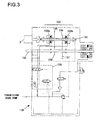
- FIG. 3 shows the configuration of the transmission 130.
- the transmission 130 is a so-called constant mesh transmission.
- the transmission 130 includes an input shaft 131 through which power from the hydraulic motor 3 is input, an output shaft 132 through which the input power is output to the axle, and a clutch device 133 that transmits or interrupts power from the input shaft 131 to the output shaft 132.
- the clutch device 133 is a wet multi-disk clutch that transmits or interrupts power by press-contacting or spacing a plurality of axially juxtaposed disks.
- the clutch device 133 causes one of a high gear 134 and a low gear 135 to rotate integrally with the input shaft 131.
- the high gear 134 and the low gear 135 are in mesh with driven gears 136 and 137 that are coupled with the output shaft 132, respectively.
- driven gears 136 and 137 that are coupled with the output shaft 132, respectively.
- rotation of the input shaft 131 is transmitted to the output shaft 132 through the low gear 135 and the driven gear 137.
- the clutch device 133 includes a high clutch 133a and the high gear 134 for transmitting power at the first transmission gear ratio and a low clutch 133b and the low gear 135 for transmitting power at the second transmission gear ratio, which is greater than the first transmission gear ratio.
- the high clutch 133a and the low clutch 133b operate upon pressure oil from a transmission control valve 138.
- the transmission control valve 138 is controlled by an instruction from the controller 10.
- the transmission control valve 138 is switched and pressure that acts upon the low clutch 133b rises, the low clutch 133b is gradually connected and then switched to the low state (refer to FIG. 3 ).
- pressure that acts upon the high clutch 133a rises due to switching of the transmission control valve 138, the high clutch 133a is gradually connected and then switched to the high state.
- a High/Low switch-type transmission as mentioned above has advantages such as lower manufacturing cost and better fuel economy compared with an automatic transmission that shifts gear automatically.
- gear shift shock occurs due to the gear ratio between the high gear 134 and the low gear 135.
- a threefold difference in gear ratio results in one third the vehicle speed and threefold the traction force when the transmission is shifted down from High to Low, thereby causing a great shock due to a decrease in the vehicle speed, slip of the tires due to an increase in the traction force, and the like.
- a gear shift shock is reduced by reducing the motor displacement angle of the hydraulic motor 3 at the time of switching from High to Low.
- the controller 10 when instructed to switch the transmission from High to Low by an operation with the High/Low selection switch 23, the controller 10 permits gear shift if the vehicle speed is less than a gear shift limit. When instructed to switch the transmission from High to Low with the vehicle speed being equal to or greater than the gear shift limit, the controller 10 permits gear shift if the vehicle speed decreases to the gear shift limit. On the other hand, when instructed to switch the transmission from High to Low by an operation with the quick shift switch 24, the controller 10 permits gear shift only if the High/Low selection switch 23 is operated to High and the vehicle speed is less than the gear shift limit. If the vehicle speed is equal to or greater than the gear shift limit and the quick shift switch 24 is operated, the controller 10 judges that a signal from the quick shift switch 24 is invalid.
- the gear shift limit is set in advance to an appropriate value so as to reduce a gear shift shock at the time of switching from High to Low (10 km/h for instance). It is to be noted that the motor displacement angle is not particularly controlled when switching from Low to High.
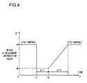
- FIG. 4 shows a shift change process from High to Low.
- the horizontal axis represents time and the vertical axis represents a motor displacement instruction value.
- a motor displacement instruction value qi is an instruction value of the motor displacement angle that is output from the controller 10 to the regulator 14 of the hydraulic motor 3. It is assumed that the vehicle is in operation in High state and the vehicle speed is less than the gear shift limit and the motor displacement instruction value qi is qa. In a normal state other than when the gear is shifted, the motor displacement is PID-controlled based upon a circuit pressure detected by the pressure detector 21.
- the controller 10 If, in this state, the operator operates the High/Low selection switch 23 or the quick shift switch 24 so as to switch the transmission from High to Low at a time point t1, the controller 10 outputs a predetermined value qb to the regulator 14 as the motor displacement instruction value qi so as to reduce the motor displacement angle.
- the predetermined value qb is set to a motor displacement angle equal to or greater than the minimum value qmin described above, so that a minimal amount of oil with which the vehicle can be driven by the hydraulic motor 3 can be ensured even if, for example, an electrical abnormality occurs at the regulator 14.
- the motor displacement instruction value qi is fixed to the predetermined value qb.
- the controller 10 outputs at a time point t2 to the transmission 140 an instruction to switch the transmission from High to Low.
- the transmission control valve 138 is switched, pressure that acts upon the low clutch 133b rises, and the low clutch 133b is gradually connected and then switched to Low state.
- the controller 10 After outputting the instruction to switch the transmission from High to Low at the time point t2, the controller 10 outputs an instruction to the regulator 14 so as to recover the motor displacement instruction value qi from the predetermined value qb to a value in accordance with the PID control during a predetermined transition time ⁇ T2.
- the motor displacement instruction value qi increases with a predetermined slope during the transition time ⁇ T2, and, after the transition time ⁇ T2 has elapsed, the PID control is resumed based upon the circuit pressure at that time point.
- the predetermined value qb of the motor displacement instruction value qi is set in advance to an appropriate value that is less than 1/3 of the motor displacement instruction value qa, e.g., approximately 1/4 of qa, at the time of the instruction to switch the transmission from High to Low in view of delay in the control system and the like.
- An appropriate value (400 msec for instance) is set in advance to the predetermined elapsed time ⁇ T1 as a latency during which from when the motor displacement instruction value qb is output to when the motor displacement angle of the hydraulic motor 3 is switched in accordance with the instruction value qb.
- the predetermined transition time ⁇ T2 is set in advance to an appropriate period of time (1 sec for example) as a ramp time during which the control of the motor displacement angle is smoothly recovered to the normal PID control.
- the predetermined value qb, the elapsed time ⁇ T1, and the transition time ⁇ T2 are not limited to the examples given above and appropriate values are set in accordance with specifications of the vehicle and the like.
- FIG. 5(a) shows an example of traveling performance diagram of a vehicle to which the travel control apparatus according to the present embodiment is applied.
- the gear ratio between the high gear 134 and the low gear 135 is assumed to be threefold.
- FIG. 5(b) shows a comparison example.
- the horizontal axis represents the vehicle speed and the vertical axis represents the traction force.
- the transmission gear is shifted from High to Low at A
- the vehicle speed becomes 1/3
- the traction force becomes threefold at the moment of shift down. This causes a great shock due to a decrease in the vehicle speed and slip of tires and the like due to an increase in the traction force.
- displacement of the hydraulic motor 3 is shifted to a small displacement side at the time of switching the transmission from High to Low.
- the motor displacement angle By shifting the motor displacement angle to a small displacement, the vehicle speed at the time of switching to Low state becomes higher, i.e., reduction in the vehicle speed decreases becomes lower and the traction force also becomes lower. This causes gear shift shock at the time of switching from High to Low to be reduced, thereby achieving a smooth gear shift operation.
- the travel control apparatus described above may be applied to a working vehicle other than a wheel loader, e.g., a road machine such as a tire roller and a road roller.
Landscapes
- Engineering & Computer Science (AREA)
- General Engineering & Computer Science (AREA)
- Mechanical Engineering (AREA)
- Mining & Mineral Resources (AREA)
- Civil Engineering (AREA)
- Structural Engineering (AREA)
- Physics & Mathematics (AREA)
- Fluid Mechanics (AREA)
- Control Of Transmission Device (AREA)
- Control Of Fluid Gearings (AREA)
- Operation Control Of Excavators (AREA)
Abstract
Description
- The present invention relates to a travel control apparatus of a working vehicle such as a wheel loader.
- There is a conventionally known working vehicle travel control apparatus that includes a transmission using a clutch that can be controlled only into a state of full engagement or a state of full disengagement, in which occurrence of a shock from when the disengaged clutch is engaged again is reduced (refer to Patent Literature 1). More specifically, occurrence of a gear shift shock when the clutch is engaged again is reduced by controlling the displacement angle of a hydraulic pump and matching the number of rotation between a power upstream-side with a power downstream-side of the clutch.
- [Patent Literature 1] Japanese Laid-Open Patent Publication No.
2002-139148 - The apparatus of
Patent Literature 1 described above is configured to reduce a gear shift shock by matching the number of rotation between a power upstream-side with a power downstream-side of the clutch, and hence a synchronization mechanism for matching the number of rotation is required. - According to first aspect of the present invention, a working vehicle travel control apparatus, comprising: a variable displacement hydraulic pump that is driven by an engine; a variable displacement hydraulic motor that is connected in a closed circuit to the hydraulic pump and driven upon pressure oil from the hydraulic pump; a first control unit that controls a motor displacement angle of the hydraulic motor by an electrical signal; a constant mesh transmission that includes a clutch device that includes a High clutch section that transmits power at a first transmission gear ratio and a Low clutch section that transmits power at a second transmission gear ratio, which is greater than the first transmission gear ratio, the constant mesh transmission that transmits or interrupts power from the hydraulic motor; and a second control unit that controls the first control unit so as to reduce the motor displacement angle to a predetermined value when the transmission is switched from the first transmission gear ratio to the second transmission gear ratio.
According to the second aspect of the present invention, in the working vehicle travel control apparatus of the first aspect, it is preferred that the predetermined value of the motor displacement angle is set to be greater than a minimum displacement angle of the hydraulic motor and a minimal motor displacement angle at which the working vehicle can be driven by the hydraulic motor.
According to the third aspect of the present invention, in the working vehicle travel control apparatus of the first or second aspect, it is preferred that the second control unit controls the first control unit so that when the transmission is switched from the first transmission gear ratio to the second transmission gear ratio, after the motor displacement angle is reduced to the predetermined value and fixed to the predetermined value for a predetermined period of time, and then the motor displacement angle is recovered.
According to the fourth aspect of the present invention, a wheel loader, comprising a travel control apparatus according to any one of the first to third aspect. - According to the present invention, a gear shift shock can be reduced at the time of switching from High to Low.
-
- [
FIG. 1] FIG. 1 is a side view of a working vehicle to which the travel control apparatus according to an embodiment of the present invention is applied. - [
FIG. 2] FIG. 2 is a diagram showing the outline structure of the travel control apparatus according to the present embodiment. - [
FIG. 3] FIG. 3 is a diagram of the configuration of a transmission. - [
FIG. 4] FIG. 4 is a diagram showing a shift change process from High to Low. - [
FIG. 5] FIG. 5(a) and FIG. 5(b) are diagrams showing a traveling performance diagram of a working vehicle to which the travel control apparatus according to the present embodiment is applied and a comparison example, respectively. - A working vehicle travel control apparatus according to an embodiment of the present invention will now be explained with reference to
FIG. 1 to FIG. 5 . -
FIG. 1 is a side view of a wheel loader that is an example of a working vehicle to which the travel control apparatus according to the present embodiment is applied. Awheel loader 100 is constituted with afront body 110 that includes anarm 111, abucket 112,tires 113, etc., and arear body 120 that includes a driver'scabin 121, anengine bay 122,tires 123, etc. Thearm 111 vertically rotates (moves up and down) on actuation of anarm cylinder 114 and thebucket 112 vertically rotates (dumps or crowds) on actuation of abucket cylinder 115. Thefront body 110 and therear body 120 are rotatably connected with each other through acenter pin 101, so that expansion and contraction of a steering cylinder (not shown in the figure) causes thefront body 110 to turn right and left with respect to therear body 120. -
FIG. 2 is a diagram showing the outline structure of the travel control apparatus according to the present embodiment. A variable displacementhydraulic pump 2, which is driven by anengine 1, and a variable displacementhydraulic motor 3 are connected in a closed circuit through a pair of main lines LA and LB and thus a so-called HST circuit is configured. - Pressure oil from a
charge pump 5, which is driven by theengine 1 is led to adisplacement cylinder 8 through a forward/reverse switching valve 6. The forward/reverse switching valve 6 is operated on a signal from acontroller 10. As illustrated, when the forward/reverse switching valve 6 is in the neutral position, pressure oil from thecharge pump 5 acts upon bothvalve chambers displacement cylinder 8 through arestrictor 7 and the forward/reverse switching valve 6. In this state, pressure acts equally upon theoil chambers piston 8c is in the neutral position. For this reason, a displacement qp of thehydraulic pump 2 becomes 0 and a pump discharge rate Q is 0. - When the forward/
reverse switching valve 6 is switched to the A side, upstream-side pressure and downstream-side pressure of therestrictor 7 acts upon thevalve chambers valve chambers cylinder 8 and thepiston 8c is displaced to the right direction in the figure. Due to this, the pump displacement dp (pump displacement amount) of thehydraulic pump 2 is increased, pressure oil from thehydraulic pump 2 is led to thehydraulic motor 3 through the main line LA, thehydraulic motor 3 rotates forward, and the vehicle travels forward. When the forward/reverse switching valve 6 is switched to the B side, thepiston 8c of thedisplacement cylinder 8 is displaced to the left direction in the figure, pressure oil from thehydraulic pump 2 is led to thehydraulic motor 3 through the main line LB, and thehydraulic motor 3 rotates reversely. - Rotation of the
hydraulic motor 3 is shifted by atransmission 130, the shifted rotation is transmitted to thetires transmission 130 can be switched between two speeds, Low and High, by an operation with a High/Low selection switch 23. - An accelerator pedal 9 is provided with an
operation amount detector 9a, which detects an operation amount of the accelerator pedal 9, and a signal from theoperation amount detector 9a is input to thecontroller 10. Thecontroller 10 outputs a rotational speed control signal to anengine control unit 1a and the engine rotational speed is controlled according to the signal from theoperation amount detector 9a. Pressure oil from thecharge pump 5, passing through therestrictor 7 and a check valve in anoverload relief valve 13, is led to the main lines LA and LB and replenished into the HST circuit. Downstream-side pressure of therestrictor 7 is restricted by acharge relief valve 12 and the maximum pressure at the main lines LA and LB is restricted by theoverload relief valve 13. - A displacement qm (motor displacement angle) of the
hydraulic motor 3 is controlled by aregulator 14. Theregulator 14, which is an electrical regulator that includes a solenoid valve, a proportional solenoid valve, etc., is driven by control current that is output from thecontroller 10 throughsignal lines displacement control lever 140 and change the motor displacement angle qm. A motor displacement control unit is provided with astopper 15. Thedisplacement control lever 140 comes to a stop against thestopper 15 so as to mechanically restrict the minimum value of the motor displacement angle qm to a predetermined value qmin. It is to be noted that when theregulator 14 is not energized, thedisplacement control lever 140 comes to a stop against thestopper 15 and the motor displacement angle qm is maintained at the minimum value qmin. With an increase in control current to be output to theregulator 14, the motor displacement angle qm increases. - The
controller 10 is configured to include an arithmetic processing unit that has a CPU, a ROM, a RAM, other peripheral circuits, etc. A signal from apressure detector 21, which detects pressure (travel load pressure Pt) at the main lines LA and LB, a signal from avehicle speed sensor 17, which detects the vehicle speed, a signal from the High/Low selection switch 23, and a signal from aquick shift switch 24 are input to thecontroller 10. Thequick shift switch 24 is a switch that is provided, separately from the High/Low selection switch 23, on a grip of a cargo handling lever (not illustrated) so as to switch between High and Low. - The
controller 10 controls the motor displacement angle qm in accordance with a travel load pressure Pt (PID control). With an increase in the travel load pressure Pt, the motor displacement angle qm gradually increases from the minimum value qmin to the maximum value qmax. The rotational speed of thehydraulic motor 2 is expressed by pump discharge rate Q × motor displacement efficiency / motor displacement qm and the vehicle speed is proportional to the motor rotational speed. Accordingly, when the travel load pressure Pt is great and the motor displacement angle qm is great, the vehicle can travel at a low speed and high torque, and, on the other hand, when the travel load Pt is little and the motor displacement angle qm is little, the vehicle can travel at a high speed and low torque. -
FIG. 3 shows the configuration of thetransmission 130. Thetransmission 130 is a so-called constant mesh transmission. Thetransmission 130 includes aninput shaft 131 through which power from thehydraulic motor 3 is input, anoutput shaft 132 through which the input power is output to the axle, and aclutch device 133 that transmits or interrupts power from theinput shaft 131 to theoutput shaft 132. - The
clutch device 133 is a wet multi-disk clutch that transmits or interrupts power by press-contacting or spacing a plurality of axially juxtaposed disks. Theclutch device 133 causes one of ahigh gear 134 and alow gear 135 to rotate integrally with theinput shaft 131. Thehigh gear 134 and thelow gear 135 are in mesh with drivengears output shaft 132, respectively. In a state where thelow gear 135 is connected to the input shaft 131 (low state), rotation of theinput shaft 131 is transmitted to theoutput shaft 132 through thelow gear 135 and the drivengear 137. In a state where thehigh gear 134 is connected to the input shaft 131 (high state), rotation of theinput shaft 131 is transmitted to theoutput shaft 132 through thehigh gear 134 and the drivengear 136. As a result, theoutput shaft 132 rotates to a predetermined gear ratio and the vehicle travels at a speed in accordance with the rotation of theoutput shaft 132. - The
clutch device 133 includes a high clutch 133a and thehigh gear 134 for transmitting power at the first transmission gear ratio and a low clutch 133b and thelow gear 135 for transmitting power at the second transmission gear ratio, which is greater than the first transmission gear ratio. The high clutch 133a and the low clutch 133b operate upon pressure oil from atransmission control valve 138. Thetransmission control valve 138 is controlled by an instruction from thecontroller 10. When thetransmission control valve 138 is switched and pressure that acts upon the low clutch 133b rises, the low clutch 133b is gradually connected and then switched to the low state (refer toFIG. 3 ). On the other hand, when pressure that acts upon the high clutch 133a rises due to switching of thetransmission control valve 138, the high clutch 133a is gradually connected and then switched to the high state. - A High/Low switch-type transmission as mentioned above has advantages such as lower manufacturing cost and better fuel economy compared with an automatic transmission that shifts gear automatically. However, at the time of switching from High to Low, gear shift shock occurs due to the gear ratio between the
high gear 134 and thelow gear 135. For example, a threefold difference in gear ratio results in one third the vehicle speed and threefold the traction force when the transmission is shifted down from High to Low, thereby causing a great shock due to a decrease in the vehicle speed, slip of the tires due to an increase in the traction force, and the like. - In order to reduce such gear shift shock, permitting gear shift from High to Low in a state where the vehicle speed is sufficiently reduced is considered. In addition, in the present embodiment, a gear shift shock is reduced by reducing the motor displacement angle of the
hydraulic motor 3 at the time of switching from High to Low. - More specifically, when instructed to switch the transmission from High to Low by an operation with the High/
Low selection switch 23, thecontroller 10 permits gear shift if the vehicle speed is less than a gear shift limit. When instructed to switch the transmission from High to Low with the vehicle speed being equal to or greater than the gear shift limit, thecontroller 10 permits gear shift if the vehicle speed decreases to the gear shift limit. On the other hand, when instructed to switch the transmission from High to Low by an operation with thequick shift switch 24, thecontroller 10 permits gear shift only if the High/Low selection switch 23 is operated to High and the vehicle speed is less than the gear shift limit. If the vehicle speed is equal to or greater than the gear shift limit and thequick shift switch 24 is operated, thecontroller 10 judges that a signal from thequick shift switch 24 is invalid. Here, the gear shift limit is set in advance to an appropriate value so as to reduce a gear shift shock at the time of switching from High to Low (10 km/h for instance). It is to be noted that the motor displacement angle is not particularly controlled when switching from Low to High. -
FIG. 4 shows a shift change process from High to Low. InFIG. 4 , the horizontal axis represents time and the vertical axis represents a motor displacement instruction value. A motor displacement instruction value qi is an instruction value of the motor displacement angle that is output from thecontroller 10 to theregulator 14 of thehydraulic motor 3. It is assumed that the vehicle is in operation in High state and the vehicle speed is less than the gear shift limit and the motor displacement instruction value qi is qa. In a normal state other than when the gear is shifted, the motor displacement is PID-controlled based upon a circuit pressure detected by thepressure detector 21. - If, in this state, the operator operates the High/
Low selection switch 23 or thequick shift switch 24 so as to switch the transmission from High to Low at a time point t1, thecontroller 10 outputs a predetermined value qb to theregulator 14 as the motor displacement instruction value qi so as to reduce the motor displacement angle. The predetermined value qb is set to a motor displacement angle equal to or greater than the minimum value qmin described above, so that a minimal amount of oil with which the vehicle can be driven by thehydraulic motor 3 can be ensured even if, for example, an electrical abnormality occurs at theregulator 14. - Before a predetermined elapsed time ΔT1 has elapsed from the time point t1, the motor displacement instruction value qi is fixed to the predetermined value qb. After the elapsed time ΔT1 has elapsed and the vehicle traction force has been sufficiently reduced, the
controller 10 outputs at a time point t2 to thetransmission 140 an instruction to switch the transmission from High to Low. In accordance with the instruction from thecontroller 10, thetransmission control valve 138 is switched, pressure that acts upon the low clutch 133b rises, and the low clutch 133b is gradually connected and then switched to Low state. - After outputting the instruction to switch the transmission from High to Low at the time point t2, the
controller 10 outputs an instruction to theregulator 14 so as to recover the motor displacement instruction value qi from the predetermined value qb to a value in accordance with the PID control during a predetermined transition time ΔT2. The motor displacement instruction value qi increases with a predetermined slope during the transition time ΔT2, and, after the transition time ΔT2 has elapsed, the PID control is resumed based upon the circuit pressure at that time point. - Here, given that the gear ratio between the
high gear 134 and thelow gear 135 is threefold, the predetermined value qb of the motor displacement instruction value qi is set in advance to an appropriate value that is less than 1/3 of the motor displacement instruction value qa, e.g., approximately 1/4 of qa, at the time of the instruction to switch the transmission from High to Low in view of delay in the control system and the like. An appropriate value (400 msec for instance) is set in advance to the predetermined elapsed time ΔT1 as a latency during which from when the motor displacement instruction value qb is output to when the motor displacement angle of thehydraulic motor 3 is switched in accordance with the instruction value qb. In addition, the predetermined transition time Δ T2 is set in advance to an appropriate period of time (1 sec for example) as a ramp time during which the control of the motor displacement angle is smoothly recovered to the normal PID control. In order to achieve a smooth switching from High to Low, the predetermined value qb, the elapsed time ΔT1, and the transition time ΔT2 are not limited to the examples given above and appropriate values are set in accordance with specifications of the vehicle and the like. - The operations of the travel control apparatus according to the present embodiment explained above will now be explained.
FIG. 5(a) shows an example of traveling performance diagram of a vehicle to which the travel control apparatus according to the present embodiment is applied. Here, the gear ratio between thehigh gear 134 and thelow gear 135 is assumed to be threefold.FIG. 5(b) shows a comparison example. InFIGS. 5(a) and 5(b) , the horizontal axis represents the vehicle speed and the vertical axis represents the traction force. As shown in the comparison example ofFIG. 5(b) , when the transmission gear is shifted from High to Low at A, the vehicle speed becomes 1/3 and the traction force becomes threefold at the moment of shift down. This causes a great shock due to a decrease in the vehicle speed and slip of tires and the like due to an increase in the traction force. - In contrast to this, as shown in
FIG. 5(a) , in the present embodiment, displacement of thehydraulic motor 3 is shifted to a small displacement side at the time of switching the transmission from High to Low. By shifting the motor displacement angle to a small displacement, the vehicle speed at the time of switching to Low state becomes higher, i.e., reduction in the vehicle speed decreases becomes lower and the traction force also becomes lower. This causes gear shift shock at the time of switching from High to Low to be reduced, thereby achieving a smooth gear shift operation. - The following advantages can be achieved according to the present embodiment explained above.
- (1) A travel control apparatus includes the variable displacement
hydraulic pump 2, which is driven by an engine, the variable displacementhydraulic motor 3, which is connected in a closed circuit to thehydraulic pump 2 and driven on pressure oil from thehydraulic pump 2, theregulator 14, which controls the motor displacement angle of thehydraulic motor 3 by an electrical signal, and theclutch device 133 that includes High clutch section (the high clutch 133a and the high gear 134), which transmits power at a first transmission gear ratio, and a Low clutch section (the low clutch 133b and the low gear 135), which transmits power at a second transmission gear ratio, which is greater than the first transmission gear ratio, and includes theconstant mesh transmission 130, which transmits or interrupts power from thehydraulic motor 3, and thecontroller 10, which controls theregulator 140 so as to reduce the motor displacement angle to the predetermined value qb when switching thetransmission 130 from the first transmission gear ratio to the second transmission gear ratio. By reducing the motor displacement angle when switching the transmission gear ratio, the vehicle speed relatively becomes higher and the traction force becomes lower compared to when the motor displacement angle is not reduced. As a result, when using the High/Low switching-type transmission 130, which has low manufacturing cost and good vehicle fuel consumption, a gear shift shock at the time of switching the transmission from High to Low can be reduced. - (2) The predetermined value qb of the motor displacement angle, which is greater than the minimum displacement angle qmin of the
hydraulic motor 3, is a minimal motor displacement angle at which a working vehicle can be driven by thehydraulic motor 3. If the predetermined value qb is 0, the vehicle becomes unable to travel when, for instance, a harness through which thehydraulic motor 3 is controlled is disconnected. By setting the predetermined value qb to a value described above, a minimal amount of oil used to move the vehicle is ensured, thereby enabling the vehicle to travel even if the harness is disconnected. - (3) When the transmission is switched from High to Low, after the motor displacement angle is reduced to the predetermined value qb and fixed to the predetermined value qb for the predetermined period of time ΔT1, and then the motor displacement angle is recovered. This allows a period of time during which the motor displacement angle is changed actually and a smooth gear shift to be achieved.
- The above explanation is merely an example and the present invention is not limited to the configuration of the above embodiment. For instance, the travel control apparatus described above may be applied to a working vehicle other than a wheel loader, e.g., a road machine such as a tire roller and a road roller.
- Although the variety of embodiments and examples of variations are described above, the present invention is not to be limited only to those contents. The scope of the present invention includes other possible embodiments invented within the scope of the technical idea of the present invention.
- The disclosure of the following priority application is herein incorporated by reference:
- Japanese Patent Application No.
2010-194083 (filed on August 31, 2010
Claims (4)
- A working vehicle travel control apparatus, comprising:a variable displacement hydraulic pump that is driven by an engine;a variable displacement hydraulic motor that is connected in a closed circuit to the hydraulic pump and driven upon pressure oil from the hydraulic pump;a first control unit that controls a motor displacement angle of the hydraulic motor by an electrical signal;a constant mesh transmission that includes a clutch device that includes a High clutch section that transmits power at a first transmission gear ratio and a Low clutch section that transmits power at a second transmission gear ratio, which is greater than the first transmission gear ratio, the constant mesh transmission that transmits or interrupts power from the hydraulic motor; anda second control unit that controls the first control unit so as to reduce the motor displacement angle to a predetermined value when the transmission is switched from the first transmission gear ratio to the second transmission gear ratio.
- A working vehicle travel control apparatus according to claim 1, wherein:the predetermined value of the motor displacement angle is set to be greater than a minimum displacement angle of the hydraulic motor and a minimal motor displacement angle at which the working vehicle can be driven by the hydraulic motor.
- A working vehicle travel control apparatus according to claim 1 or claim 2, wherein:the second control unit controls the first control unit so that when the transmission is switched from the first transmission gear ratio to the second transmission gear ratio, after the motor displacement angle is reduced to the predetermined value and fixed to the predetermined value for a predetermined period of time, and then the motor displacement angle is recovered.
- A wheel loader, comprising a travel control apparatus according to any one of claim 1 to claim 3.
Applications Claiming Priority (2)
| Application Number | Priority Date | Filing Date | Title |
|---|---|---|---|
| JP2010194083A JP5301509B2 (en) | 2010-08-31 | 2010-08-31 | Travel control device for work vehicle |
| PCT/JP2011/064570 WO2012029389A1 (en) | 2010-08-31 | 2011-06-24 | Travel control apparatus for working vehicle |
Publications (2)
| Publication Number | Publication Date |
|---|---|
| EP2589836A1 true EP2589836A1 (en) | 2013-05-08 |
| EP2589836A4 EP2589836A4 (en) | 2015-09-23 |
Family
ID=45772501
Family Applications (1)
| Application Number | Title | Priority Date | Filing Date |
|---|---|---|---|
| EP11821407.1A Withdrawn EP2589836A4 (en) | 2010-08-31 | 2011-06-24 | Travel control apparatus for working vehicle |
Country Status (6)
| Country | Link |
|---|---|
| US (2) | US20130152574A1 (en) |
| EP (1) | EP2589836A4 (en) |
| JP (1) | JP5301509B2 (en) |
| KR (1) | KR20130124475A (en) |
| CN (1) | CN103026099A (en) |
| WO (1) | WO2012029389A1 (en) |
Cited By (2)
| Publication number | Priority date | Publication date | Assignee | Title |
|---|---|---|---|---|
| US20210123216A1 (en) * | 2019-03-13 | 2021-04-29 | Hitachi Construction Machinery Co., Ltd. | Loading vehicle |
| EP4060126A4 (en) * | 2019-11-14 | 2023-01-18 | Hyundai Doosan Infracore Co., Ltd. | CONSTRUCTION MACHINERY WITH AN AUTOMATIC GEARBOX AND GEARBOX CONTROL METHOD |
Families Citing this family (15)
| Publication number | Priority date | Publication date | Assignee | Title |
|---|---|---|---|---|
| EP2754757B1 (en) * | 2011-09-07 | 2017-11-01 | Hitachi Construction Machinery Tierra Co., Ltd. | Construction machine with protection mode of operation |
| JP5754397B2 (en) | 2012-03-09 | 2015-07-29 | 三菱電機株式会社 | Manufacturing method of vertical trench IGBT |
| JP6258593B2 (en) * | 2013-03-25 | 2018-01-10 | 日立建機株式会社 | Automatic transmission for work vehicle |
| JP5899167B2 (en) * | 2013-08-08 | 2016-04-06 | 日立建機株式会社 | Automatic transmission for work vehicle |
| US9759313B2 (en) * | 2014-11-26 | 2017-09-12 | Polaris Industries Inc. | Electronic shifting of a transmission |
| US9746070B2 (en) | 2014-11-26 | 2017-08-29 | Polaris Industries Inc. | Electronic control of a transmission |
| JP6438368B2 (en) * | 2015-09-18 | 2018-12-12 | ヤンマー株式会社 | Work vehicle |
| US10519627B2 (en) | 2017-02-08 | 2019-12-31 | Caterpillar Inc. | Pull-slip control system for track-type tractor and track-type tractor operating method |
| CN107310384A (en) * | 2017-07-27 | 2017-11-03 | 天津工程机械研究院有限公司 | A kind of all-hydraulic walking transmission system of wheel loader |
| JP6961643B2 (en) | 2019-03-29 | 2021-11-05 | 日立建機株式会社 | Wheel type work vehicle |
| CA3151536A1 (en) | 2019-09-19 | 2021-03-25 | Clark Equipment Company | Drive motor displacement control |
| CN110594409B (en) * | 2019-10-18 | 2024-03-12 | 三一汽车制造有限公司 | Flexible gear shifting hydraulic system, control method thereof and engineering machinery |
| WO2022113784A1 (en) * | 2020-11-26 | 2022-06-02 | 日立建機株式会社 | Rolling machine |
| US12234626B2 (en) | 2022-03-08 | 2025-02-25 | Caterpillar Sarl | Maintenance-service system |
| JP2025150116A (en) * | 2024-03-27 | 2025-10-09 | 株式会社 神崎高級工機製作所 | Transmission Structure |
Family Cites Families (16)
| Publication number | Priority date | Publication date | Assignee | Title |
|---|---|---|---|---|
| SE440262B (en) * | 1983-01-13 | 1985-07-22 | Stensele Mek Verkstad Ab | SYNCHRONIZED, HYDROSTATIC-MECHANICAL GEAR |
| US4766779A (en) * | 1984-03-05 | 1988-08-30 | Fabco Automotive Corporation | Hydrostatic transmission assembly and method of increasing the torque and speed range thereof |
| IT1245204B (en) * | 1991-03-15 | 1994-09-13 | Fritz Carl Anton Hurth | SPEED CHANGE WITH HYDROSTATIC MOTORS PARTICULARLY FOR EARTH-MOVING MACHINES |
| DE4223846C2 (en) * | 1992-07-20 | 1996-03-28 | Hydromatik Gmbh | Gear unit for arrangement between a drive motor and a consumer |
| JP3431651B2 (en) * | 1992-12-28 | 2003-07-28 | 日立建機株式会社 | Hydraulic motor drive circuit for work vehicle traveling |
| DE19524189C2 (en) * | 1995-07-03 | 1997-07-17 | Brueninghaus Hydromatik Gmbh | Hydrostatic drive with downstream powershift transmission |
| JP4521108B2 (en) * | 2000-11-06 | 2010-08-11 | ヤンマー株式会社 | HST swash plate control mechanism of work vehicle |
| JP2002174333A (en) * | 2000-12-05 | 2002-06-21 | Hitachi Constr Mach Co Ltd | Wheeled work vehicle |
| DE10133358B4 (en) * | 2001-07-10 | 2006-03-16 | Brueninghaus Hydromatik Gmbh | Hydrostatic drive and method for changing gears of a hydrostatic transmission downstream of a manual transmission |
| US20050161090A1 (en) * | 2002-04-26 | 2005-07-28 | Hitachi Construction Machinery Co., Ltd | Travel control device of hydraulically driven vehicle, hydraulically driven vehicle, and wheel hydraulic shovel |
| JP4528238B2 (en) * | 2005-09-30 | 2010-08-18 | 株式会社クボタ | Speed control structure of work vehicle |
| DE102005058937A1 (en) * | 2005-10-27 | 2007-05-31 | Brueninghaus Hydromatik Gmbh | Method and gear arrangement for changing gears |
| DE102006036317A1 (en) * | 2006-06-28 | 2008-01-03 | Brueninghaus Hydromatik Gmbh | Method for controlling a transmission ratio |
| CN101479508A (en) * | 2006-06-28 | 2009-07-08 | 布鲁宁赫斯海诺马帝克有限公司 | Method of controlling a transmission ratio |
| JP4295308B2 (en) * | 2006-12-04 | 2009-07-15 | 日立建機株式会社 | Travel drive device for work vehicle |
| JP5543117B2 (en) | 2009-02-25 | 2014-07-09 | 株式会社岡村製作所 | Chair backrest device |
-
2010
- 2010-08-31 JP JP2010194083A patent/JP5301509B2/en not_active Expired - Fee Related
-
2011
- 2011-06-24 EP EP11821407.1A patent/EP2589836A4/en not_active Withdrawn
- 2011-06-24 US US13/818,799 patent/US20130152574A1/en not_active Abandoned
- 2011-06-24 CN CN2011800368200A patent/CN103026099A/en active Pending
- 2011-06-24 KR KR1020137001919A patent/KR20130124475A/en not_active Withdrawn
- 2011-06-24 WO PCT/JP2011/064570 patent/WO2012029389A1/en not_active Ceased
-
2015
- 2015-12-31 US US14/985,748 patent/US20160194854A1/en not_active Abandoned
Cited By (4)
| Publication number | Priority date | Publication date | Assignee | Title |
|---|---|---|---|---|
| US20210123216A1 (en) * | 2019-03-13 | 2021-04-29 | Hitachi Construction Machinery Co., Ltd. | Loading vehicle |
| EP3795755A4 (en) * | 2019-03-13 | 2022-02-16 | Hitachi Construction Machinery Co., Ltd. | GOODS HANDLING WORK VEHICLE |
| US11891781B2 (en) * | 2019-03-13 | 2024-02-06 | Hitachi Construction Machinery Co., Ltd. | Loading vehicle |
| EP4060126A4 (en) * | 2019-11-14 | 2023-01-18 | Hyundai Doosan Infracore Co., Ltd. | CONSTRUCTION MACHINERY WITH AN AUTOMATIC GEARBOX AND GEARBOX CONTROL METHOD |
Also Published As
| Publication number | Publication date |
|---|---|
| KR20130124475A (en) | 2013-11-14 |
| EP2589836A4 (en) | 2015-09-23 |
| WO2012029389A1 (en) | 2012-03-08 |
| US20160194854A1 (en) | 2016-07-07 |
| JP5301509B2 (en) | 2013-09-25 |
| JP2012052580A (en) | 2012-03-15 |
| US20130152574A1 (en) | 2013-06-20 |
| CN103026099A (en) | 2013-04-03 |
Similar Documents
| Publication | Publication Date | Title |
|---|---|---|
| US20130152574A1 (en) | Working Vehicle Travel Control Apparatus | |
| EP2687704B1 (en) | Drive control device for work vehicle | |
| CN101606010B (en) | Clutch control device for hydraulically driven vehicle | |
| US10801183B2 (en) | Wheel loader | |
| US8475334B2 (en) | Load-sensitive automatic transmission system for agricultural electric vehicle | |
| EP3415778A1 (en) | Wheel loader, method for controlling wheel loader, and system for controlling wheel loader | |
| US20150274149A1 (en) | Hydrostatic Traction Drive in Closed Hydraulic Circuit and Method for Controlling the Hydrostatic Traction Drive | |
| CN102066814B (en) | Motor grader | |
| EP3362708B1 (en) | Agricultural vehicle driveline | |
| JP5833168B2 (en) | Gearbox for work vehicle | |
| US20130261909A1 (en) | Rollback prevention system for mobile machine | |
| SE533648C2 (en) | Work Vehicles | |
| JP2005280559A (en) | Vehicular start control device | |
| US20020119865A1 (en) | Hydraulic change speed system for a working vehicle | |
| JP5426731B2 (en) | Transmission device for work vehicle | |
| JP2005280558A (en) | Vehicular start control device | |
| EP4098911B1 (en) | A transmission of a vehicle | |
| US9970541B2 (en) | Gear box for a working machine and a method for controlling a gear box | |
| US20160186857A1 (en) | Method of controlling machines with continuously variable transmission | |
| JP5592539B2 (en) | Transmission device for work vehicle | |
| JP4796432B2 (en) | Work vehicle travel stop control device | |
| JP2004034724A (en) | Work machine traveling structure | |
| JP5215122B2 (en) | Working gear shifting structure | |
| SE533419C2 (en) | Control unit which enables control to reduce slipping of a working vehicle | |
| JPH06229470A (en) | Work vehicle traveling speed change structure |
Legal Events
| Date | Code | Title | Description |
|---|---|---|---|
| PUAI | Public reference made under article 153(3) epc to a published international application that has entered the european phase |
Free format text: ORIGINAL CODE: 0009012 |
|
| 17P | Request for examination filed |
Effective date: 20130130 |
|
| AK | Designated contracting states |
Kind code of ref document: A1 Designated state(s): AL AT BE BG CH CY CZ DE DK EE ES FI FR GB GR HR HU IE IS IT LI LT LU LV MC MK MT NL NO PL PT RO RS SE SI SK SM TR |
|
| DAX | Request for extension of the european patent (deleted) | ||
| RA4 | Supplementary search report drawn up and despatched (corrected) |
Effective date: 20150824 |
|
| RIC1 | Information provided on ipc code assigned before grant |
Ipc: F16H 61/02 20060101ALI20150818BHEP Ipc: F16H 47/02 20060101AFI20150818BHEP |
|
| RAP1 | Party data changed (applicant data changed or rights of an application transferred) |
Owner name: KCM CORPORATION |
|
| STAA | Information on the status of an ep patent application or granted ep patent |
Free format text: STATUS: THE APPLICATION HAS BEEN WITHDRAWN |
|
| 18W | Application withdrawn |
Effective date: 20170110 |