EP2589781B1 - Hohle Gebläseflügelanpassung mit verschiedenen Füllmaterialien und Verfahren zur Gestaltung dieses Gebläseflügels - Google Patents
Hohle Gebläseflügelanpassung mit verschiedenen Füllmaterialien und Verfahren zur Gestaltung dieses Gebläseflügels Download PDFInfo
- Publication number
- EP2589781B1 EP2589781B1 EP12190239.9A EP12190239A EP2589781B1 EP 2589781 B1 EP2589781 B1 EP 2589781B1 EP 12190239 A EP12190239 A EP 12190239A EP 2589781 B1 EP2589781 B1 EP 2589781B1
- Authority
- EP
- European Patent Office
- Prior art keywords
- fan blade
- channels
- set forth
- damping
- fan
- Prior art date
- Legal status (The legal status is an assumption and is not a legal conclusion. Google has not performed a legal analysis and makes no representation as to the accuracy of the status listed.)
- Active
Links
Images


Classifications
-
- F—MECHANICAL ENGINEERING; LIGHTING; HEATING; WEAPONS; BLASTING
- F02—COMBUSTION ENGINES; HOT-GAS OR COMBUSTION-PRODUCT ENGINE PLANTS
- F02K—JET-PROPULSION PLANTS
- F02K3/00—Plants including a gas turbine driving a compressor or a ducted fan
- F02K3/02—Plants including a gas turbine driving a compressor or a ducted fan in which part of the working fluid by-passes the turbine and combustion chamber
- F02K3/04—Plants including a gas turbine driving a compressor or a ducted fan in which part of the working fluid by-passes the turbine and combustion chamber the plant including ducted fans, i.e. fans with high volume, low pressure outputs, for augmenting the jet thrust, e.g. of double-flow type
- F02K3/06—Plants including a gas turbine driving a compressor or a ducted fan in which part of the working fluid by-passes the turbine and combustion chamber the plant including ducted fans, i.e. fans with high volume, low pressure outputs, for augmenting the jet thrust, e.g. of double-flow type with front fan
-
- F—MECHANICAL ENGINEERING; LIGHTING; HEATING; WEAPONS; BLASTING
- F01—MACHINES OR ENGINES IN GENERAL; ENGINE PLANTS IN GENERAL; STEAM ENGINES
- F01D—NON-POSITIVE DISPLACEMENT MACHINES OR ENGINES, e.g. STEAM TURBINES
- F01D5/00—Blades; Blade-carrying members; Heating, heat-insulating, cooling or antivibration means on the blades or the members
- F01D5/12—Blades
- F01D5/14—Form or construction
- F01D5/18—Hollow blades, i.e. blades with cooling or heating channels or cavities; Heating, heat-insulating or cooling means on blades
-
- F—MECHANICAL ENGINEERING; LIGHTING; HEATING; WEAPONS; BLASTING
- F01—MACHINES OR ENGINES IN GENERAL; ENGINE PLANTS IN GENERAL; STEAM ENGINES
- F01D—NON-POSITIVE DISPLACEMENT MACHINES OR ENGINES, e.g. STEAM TURBINES
- F01D5/00—Blades; Blade-carrying members; Heating, heat-insulating, cooling or antivibration means on the blades or the members
- F01D5/12—Blades
- F01D5/26—Antivibration means not restricted to blade form or construction or to blade-to-blade connections or to the use of particular materials
-
- F—MECHANICAL ENGINEERING; LIGHTING; HEATING; WEAPONS; BLASTING
- F01—MACHINES OR ENGINES IN GENERAL; ENGINE PLANTS IN GENERAL; STEAM ENGINES
- F01D—NON-POSITIVE DISPLACEMENT MACHINES OR ENGINES, e.g. STEAM TURBINES
- F01D5/00—Blades; Blade-carrying members; Heating, heat-insulating, cooling or antivibration means on the blades or the members
- F01D5/12—Blades
- F01D5/28—Selecting particular materials; Particular measures relating thereto; Measures against erosion or corrosion
-
- F—MECHANICAL ENGINEERING; LIGHTING; HEATING; WEAPONS; BLASTING
- F02—COMBUSTION ENGINES; HOT-GAS OR COMBUSTION-PRODUCT ENGINE PLANTS
- F02C—GAS-TURBINE PLANTS; AIR INTAKES FOR JET-PROPULSION PLANTS; CONTROLLING FUEL SUPPLY IN AIR-BREATHING JET-PROPULSION PLANTS
- F02C7/00—Features, components parts, details or accessories, not provided for in, or of interest apart form groups F02C1/00 - F02C6/00; Air intakes for jet-propulsion plants
-
- F—MECHANICAL ENGINEERING; LIGHTING; HEATING; WEAPONS; BLASTING
- F05—INDEXING SCHEMES RELATING TO ENGINES OR PUMPS IN VARIOUS SUBCLASSES OF CLASSES F01-F04
- F05D—INDEXING SCHEME FOR ASPECTS RELATING TO NON-POSITIVE-DISPLACEMENT MACHINES OR ENGINES, GAS-TURBINES OR JET-PROPULSION PLANTS
- F05D2260/00—Function
- F05D2260/94—Functionality given by mechanical stress related aspects such as low cycle fatigue [LCF] of high cycle fatigue [HCF]
-
- Y—GENERAL TAGGING OF NEW TECHNOLOGICAL DEVELOPMENTS; GENERAL TAGGING OF CROSS-SECTIONAL TECHNOLOGIES SPANNING OVER SEVERAL SECTIONS OF THE IPC; TECHNICAL SUBJECTS COVERED BY FORMER USPC CROSS-REFERENCE ART COLLECTIONS [XRACs] AND DIGESTS
- Y10—TECHNICAL SUBJECTS COVERED BY FORMER USPC
- Y10T—TECHNICAL SUBJECTS COVERED BY FORMER US CLASSIFICATION
- Y10T29/00—Metal working
- Y10T29/49—Method of mechanical manufacture
- Y10T29/49316—Impeller making
- Y10T29/49336—Blade making
- Y10T29/49339—Hollow blade
Definitions
- This application relates to a hollow fan blade for a gas turbine engine.
- Gas turbine engines may be provided with a fan for delivering air to a compressor section. From the compressor section, the air is compressed and delivered into a combustion section. The combustion section mixes fuel with the air and combusts the combination. Products of the combustion pass downstream over turbine rotors which are driven to rotate and in turn rotate the compressor and fan.
- the fan may include a rotor having a plurality of blades.
- One type of fan blade is a hollow fan blade having a plurality of channels defined by intermediate ribs in a main fan blade body. An outer skin is attached over the main fan blade body to close off the channels.
- the blades are subject to a number of challenges, including internal stresses that vary along the length of the fan blade.
- stiffening filler materials into the channels.
- the stiffening materials may be honeycomb, corrugated or metal foam.
- JP 2007 085339 A which shows the technical features of the preamble of the independent claims, discloses a prior art rotor assembly for a gas turbine.
- EP 1 811 129 A2 discloses prior art aerofoils for gas turbine engines.
- EP 0 926 312 A2 discloses a prior art damped turbomachine blade.
- EP 1 626 161 A1 discloses a prior art method of supressing the aero-elastic response of a row of blades on a steam turbine wheel.
- FR 2 762 644 A1 discloses a prior art steam turbine blade having areas of different densities.
- EP 2 233 239 A2 discloses a prior art method of manufacturing a component comprising an internal structure.
- a fan blade as set forth in claim 1.
- At least one of the channels may extend into the main body to a closed end, from an open end.
- the fan blade may additionally or alternatively include a cover skin bonded to at least one of the ribs.
- the cover skin may cover the open end of the at least one channel.
- the first material may be utilized in a channel adjacent radially inner locations, while said second material may be utilized within the same channel at radially outer locations.
- At least one of the channels may include only said first material.
- At least one other of the channels may include only said second material.
- a node may be identified on an area of bending concern along said airfoil, and said second material may be included in at least one of said channels at a location selected to support said airfoil at said node.
- the first material may be both radially outwardly and radially inwardly of the second material in the channel associated with the node.
- both the first and the second material may be of a lower density than the material forming said main body.
- the method may include identifying a vibrational node in the hollow fan blade.
- the method may include placing a damping material in the channels at an area associated with said node.
- Another embodiment addresses a gas turbine engine that includes a fan section delivering air into a compressor section. Air is compressed by the compressor section and delivered into a combustor where it is mixed with fuel and combusted. Products of the combustion pass downstream over a turbine section.
- the fan section includes a plurality of fan blades of any of the foregoing fan blades.
- At least one of the channels extends into the main body to a closed end, from an open end.
- a cover skin is bonded to at least one of the ribs.
- a gas turbine engine 210 is shown in Figure 1A .
- the engine 210 includes a fan 250 (which includes a plurality of fan blades 20), a compressor section 254 (which includes both a low pressure compressor 256 and a high pressure compressor 258), a combustor 260, and a turbine section 262 (which includes both a high pressure turbine 264 and a low pressure turbine 266).
- the high pressure compressor 258 is driven, via a first spool 268, by the high pressure turbine 264.
- the low pressure compressor 256 is driven, via a second spool 270, by the low pressure turbine 266.
- Also driven by the low pressure turbine 266 are the fan blades 20 of the fan 250, which fan is coupled to the second spool 270 via a gear 272.
- the fan 250 delivers air into compressor section 254. Air compressed by the compressor section is delivered into combustor 260. Products of the combustion in the combustor pass downstream over turbine section 262.
- a fan blade 20 is illustrated in Figure 1B having an airfoil 18 extending radially outwardly from a dovetail 24.
- a leading edge 21 and a trailing edge 22 define the forward and rear limits of the airfoil 18.
- a fan rotor 16 receives the dovetail 24 to mount the fan blade with the airfoil 18 extending radially outwardly. As the rotor is driven to rotate, it carries the fan blade with it. There are higher stresses in fan blade 20 adjacent to the rotor 16 then occur radially outwardly.
- Figure 2 shows a cross-section of the fan blade 20, at the airfoil 18.
- the leading edge 21 carries a cap 37 secured to a main body 28.
- a cover skin 32 closes off cavities or channels 30 in the main body 28.
- the main body 28, the cap 37, and the skin 32 may all be formed of aluminum or various aluminum alloys. Other materials, such as titanium, titanium alloys or appropriate metals may alternatively be utilized.
- the fan blade is shown having one cover, and the channels 30 having a closed inner end, it is also possible that the main body would provide a channel extending across its entire thickness, with covers at each side.
- a plurality of ribs 26 separate channels 30 in the cross-section illustrated in Figure 2 .
- filler material 100 may be deposited within the channels 30.
- the filler material would typically be of a lighter weight than the main body 28.
- distinct types of filler materials are utilized across the areas of the fan blade 20. While the drawing shows the material 100 completely filling channels 30, of course it need not do so.
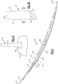
- Figure 3 shows the main body 28.
- a filler material 100 is deposited within the channel.
- the filler material has only been utilized to provide stiffness.
- the filler material can be provided by two distinct materials 102 and 104 as shown in Figure 3 .
- channels such as channel 101 which extends only for a portion of the radial extent of the main body 28 may be filled with only material 102.
- Material 102 may be selected to provide additional stiffness.
- corrugated material may be used.
- Other channels, such as channel 103, which extends somewhat further radially outwardly may have a portion filled with stiffness material 102, but also a portion of material 104 which is selected for damping characteristics.
- Such a dampening material is a rubber foam.
- Channel 41 is shown provided only with the damping material 104.
- each of the channels can be provided with distinct characteristics based upon their location across the airfoil.
- the material 104 allows a designer to achieve desired characteristics.
- the material 102 provides greater opportunities.
- some channels may have no material, if appropriate.
- Channel 300 is an example.
- a node or area of significant bending due to vibration, has been identified at the location 112. Of course, more than one node may be identified.
- the damping material 104 may be provided at that location, while a stiffening material 102 is utilized at radially inner and outer locations relative to area 112.
- this Application recognizes that there may be areas within the hollow fan blade that will benefit from each of the two types of materials.
- the invention would extend to three or more types of distinct materials, again each selected for the challenges raised at the particular location.
- materials 102 and 104 would both be significantly lighter weight or lighter density than the material of the main body 28. Thus, they do not increase the overall mass of the main body to the extent it would be increased if the main body was simply solid.
- the material 102 would have greater stiffness than the material 104, and the material 104 would have better damping characteristics than the material 102.
- One stiffening product that could be used is Duocel aluminum foam, from ERG Aerospace Corp.
- An appropriate damping material is AMS-3356 silicone rubber compound. Of course, other materials can be used.
Landscapes
- Engineering & Computer Science (AREA)
- Mechanical Engineering (AREA)
- General Engineering & Computer Science (AREA)
- Chemical & Material Sciences (AREA)
- Combustion & Propulsion (AREA)
- Materials Engineering (AREA)
- Structures Of Non-Positive Displacement Pumps (AREA)
- Turbine Rotor Nozzle Sealing (AREA)
Claims (13)
- Gebläseflügel (20), umfassend:einen Hauptkörper, der sich zwischen einer Vorderkante (21) und einer Hinterkante (22) erstreckt, und Kanäle (30), die in den Hauptkörper gebildet sind, mit einer Vielzahl von Rippen (26), die sich zwischen den Kanälen (30) erstreckt, wobei der Gebläseflügel (20) einen Schwalbenschwanz (24) und ein Schaufelprofil (18) aufweist, das sich von dem Schwalbenschwanz (24) radial nach außen erstreckt; undzumindest zwei Materialien, die innerhalb der Kanäle (30) abgeschieden sind, wobei ein erstes Material (102) ausgewählt ist, um dem Gebläseflügel (20) zusätzliche Steifigkeit bereitzustellen und ein zweites Material (104) aufgrund von Dämpfungseigenschaften ausgewählt ist, dadurch gekennzeichnet, dass das erste Material (102) ein Metallschaum ist, das zweite Material (104) ein Gummischaum ist, das erste Material (102) eine höhere Steifigkeit relativ zu dem zweiten Material (104) aufweist und das zweite Material (104) bessere Dämpfungseigenschaften als das erste Material (102) aufweist.
- Gebläseflügel (20) nach Anspruch 1, wobei das erste Material (102) in einem Kanal (30) an radial inneren Stellen verwendet wird, während das zweite Material (104) innerhalb desselben Kanals (30) an radial äußeren Stellen verwendet wird.
- Gebläseflügel (20) nach Anspruch 1 oder 2, wobei zumindest einer der Kanäle (30) nur das erste Material (102) beinhaltet.
- Gebläseflügel (20) nach einem vorhergehenden Anspruch, wobei zumindest einer der Kanäle (30) nur das zweite Material (104) beinhaltet.
- Gebläseflügel (20) nach einem vorhergehenden Anspruch, wobei ein Knoten an einem Bereich mit Biegebedenken entlang des Schaufelprofils (18) identifiziert ist und das zweite Material (104) in zumindest einem der Kanäle (30) an einer Stelle enthalten ist, die ausgewählt ist, um das Schaufelprofil (18) an dem Knoten zu stützen.
- Gebläseflügel (20) nach Anspruch 5, wobei es das erste Material (102) sowohl radial auswärts als auch radial einwärts des zweiten Materials (104) in dem Kanal gibt, der mit dem Knoten verbunden ist.
- Gebläseflügel (20) nach einem vorhergehenden Anspruch, wobei sowohl das erste als auch das zweite Material (102, 104) von einer geringeren Dichte als das Material sind, das den Hauptkörper bildet.
- Gebläseflügel nach einem vorhergehenden Anspruch, wobei zumindest ein Kanal (30) kein Material aufweist.
- Verfahren zur Gestaltung eines Gebläseflügels (20), die folgenden Schritte umfassend:Identifizieren von Bereichen innerhalb eines hohlen Gebläseflügels (20), die von zusätzlicher Versteifung profitieren würden, und anderen Bereichen, die von zusätzlicher Dämpfung profitieren würden;Platzieren eines Dämpfungsmaterials (104) in Kanälen (30), die innerhalb des Gebläseflügels (20) gebildet sind, an den Stellen, die von zusätzlicher Dämpfung profitieren; undPlatzieren eines Versteifungsmaterials (102) an Stellen innerhalb des Kanals (30), die von zusätzlicher Steifigkeit profitieren, dadurch gekennzeichnet, dassdas Versteifungsmaterial (102) ein Metallschaum ist, das Dämpfungsmaterial (104) ein Gummischaum ist, das Versteifungsmaterial (102) eine höhere Steifigkeit relativ zu dem Dämpfungsmaterial (104) aufweist und das Dämpfungsmaterial (104) bessere Dämpfungseigenschaften als das Versteifungsmaterial (102) aufweist.
- Verfahren nach Anspruch 9, ferner umfassend das Identifizieren eines Vibrationsknotens in dem hohlen Gebläseflügel, und optional das Platzieren eines Dämpfungsmaterials (104) in den Kanälen (30) an einem Bereich, der mit dem Knoten verbunden ist.
- Gasturbinenmotor (210), der einen Gebläseabschnitt (250) umfasst, der Luft in einen Verdichterabschnitt (254) abgibt, wobei Luft durch den Verdichterabschnitt (254) verdichtet und in eine Brennkammer (260) abgegeben wird, in der sie mit Kraftstoff vermischt und verbrannt wird, wobei Produkte der Verbrennung stromabwärts über einen Turbinenabschnitt (262) verlaufen, wobei der Gebläseabschnitt (250) eine Vielzahl von Gebläseflügeln (20) beinhaltet, wobei jeder der Gebläseflügel (20) nach einem vorhergehenden Anspruch ist.
- Gebläseflügel (20) oder Gasturbinenmotor (210) nach einem der Ansprüche 1 bis 8 oder 11, wobei sich zumindest einer der Kanäle (30) in den Hauptkörper von einem offenen Ende zu einem geschlossenen Ende erstreckt.
- Gebläseflügel (20) oder Gasturbinenmotor (210) nach Anspruch 12, ferner umfassend eine Deckhaut (32), die an zumindest eine der Rippen (26) gebunden ist, und wobei die Deckhaut optional das offene Ende des zumindest einen Kanals (30) abdeckt (32).
Applications Claiming Priority (1)
| Application Number | Priority Date | Filing Date | Title |
|---|---|---|---|
| US13/288,250 US8763360B2 (en) | 2011-11-03 | 2011-11-03 | Hollow fan blade tuning using distinct filler materials |
Publications (3)
| Publication Number | Publication Date |
|---|---|
| EP2589781A2 EP2589781A2 (de) | 2013-05-08 |
| EP2589781A3 EP2589781A3 (de) | 2017-05-31 |
| EP2589781B1 true EP2589781B1 (de) | 2020-01-01 |
Family
ID=47227456
Family Applications (1)
| Application Number | Title | Priority Date | Filing Date |
|---|---|---|---|
| EP12190239.9A Active EP2589781B1 (de) | 2011-11-03 | 2012-10-26 | Hohle Gebläseflügelanpassung mit verschiedenen Füllmaterialien und Verfahren zur Gestaltung dieses Gebläseflügels |
Country Status (7)
| Country | Link |
|---|---|
| US (1) | US8763360B2 (de) |
| EP (1) | EP2589781B1 (de) |
| JP (1) | JP2013096416A (de) |
| KR (1) | KR20130049151A (de) |
| CA (1) | CA2794013C (de) |
| IL (1) | IL222795A (de) |
| SG (1) | SG189616A1 (de) |
Families Citing this family (23)
| Publication number | Priority date | Publication date | Assignee | Title |
|---|---|---|---|---|
| US8997494B2 (en) * | 2012-09-28 | 2015-04-07 | United Technologies Corporation | Gas turbine engine fan blade airfoil profile |
| WO2015102715A2 (en) * | 2013-10-30 | 2015-07-09 | United Technologies Corporation | Fan blade composite ribs |
| WO2015099861A2 (en) | 2013-10-30 | 2015-07-02 | United Technologies Corporation | Fan blade composite segments |
| US10316670B2 (en) | 2013-12-05 | 2019-06-11 | United Technologies Corporation | Hollow blade having internal damper |
| EP2942481B1 (de) | 2014-05-07 | 2019-03-27 | Rolls-Royce Corporation | Rotor für einen gasturbinenmotor |
| US20160177732A1 (en) * | 2014-07-22 | 2016-06-23 | United Technologies Corporation | Hollow fan blade for a gas turbine engine |
| US9737930B2 (en) | 2015-01-20 | 2017-08-22 | United Technologies Corporation | Dual investment shelled solid mold casting of reticulated metal foams |
| US9789534B2 (en) | 2015-01-20 | 2017-10-17 | United Technologies Corporation | Investment technique for solid mold casting of reticulated metal foams |
| US9789536B2 (en) | 2015-01-20 | 2017-10-17 | United Technologies Corporation | Dual investment technique for solid mold casting of reticulated metal foams |
| US9884363B2 (en) | 2015-06-30 | 2018-02-06 | United Technologies Corporation | Variable diameter investment casting mold for casting of reticulated metal foams |
| US9731342B2 (en) | 2015-07-07 | 2017-08-15 | United Technologies Corporation | Chill plate for equiax casting solidification control for solid mold casting of reticulated metal foams |
| US20170370375A1 (en) * | 2016-06-22 | 2017-12-28 | United Technologies Corporation | Fan blade filler |
| US20180038386A1 (en) * | 2016-08-08 | 2018-02-08 | United Technologies Corporation | Fan blade with composite cover |
| US10557353B2 (en) | 2017-10-18 | 2020-02-11 | United Technologies Corporation | Hollow fan blade constrained layer damper |
| US11015461B2 (en) | 2017-12-21 | 2021-05-25 | General Electric Company | Composite hollow blade and a method of forming the composite hollow blade |
| FR3081370B1 (fr) * | 2018-05-22 | 2020-06-05 | Safran Aircraft Engines | Corps d'aube et aube en materiau composite ayant un renfort fibreux compose d'un tissage tridimensionnel et de fibres courtes et leur procede de fabrication |
| US11136888B2 (en) * | 2018-10-18 | 2021-10-05 | Raytheon Technologies Corporation | Rotor assembly with active damping for gas turbine engines |
| US10995632B2 (en) | 2019-03-11 | 2021-05-04 | Raytheon Technologies Corporation | Damped airfoil for a gas turbine engine |
| US11371358B2 (en) * | 2020-02-19 | 2022-06-28 | General Electric Company | Turbine damper |
| US11624287B2 (en) * | 2020-02-21 | 2023-04-11 | Raytheon Technologies Corporation | Ceramic matrix composite component having low density core and method of making |
| US11365636B2 (en) | 2020-05-25 | 2022-06-21 | General Electric Company | Fan blade with intrinsic damping characteristics |
| US12571314B2 (en) | 2023-07-07 | 2026-03-10 | General Electric Company | Composite airfoil assembly for a turbine engine |
| US12203390B1 (en) * | 2023-07-07 | 2025-01-21 | General Electric Company | Composite airfoil assembly for a turbine engine |
Family Cites Families (19)
| Publication number | Priority date | Publication date | Assignee | Title |
|---|---|---|---|---|
| US4118147A (en) * | 1976-12-22 | 1978-10-03 | General Electric Company | Composite reinforcement of metallic airfoils |
| JPH08307946A (ja) * | 1995-05-12 | 1996-11-22 | Nec Corp | Phs端末無効化方式 |
| US5931641A (en) * | 1997-04-25 | 1999-08-03 | General Electric Company | Steam turbine blade having areas of different densities |
| US6039542A (en) * | 1997-12-24 | 2000-03-21 | General Electric Company | Panel damped hybrid blade |
| US6033186A (en) * | 1999-04-16 | 2000-03-07 | General Electric Company | Frequency tuned hybrid blade |
| US6910483B2 (en) * | 2001-12-10 | 2005-06-28 | Resmed Limited | Double-ended blower and volutes therefor |
| DE10301755A1 (de) * | 2003-01-18 | 2004-07-29 | Rolls-Royce Deutschland Ltd & Co Kg | Fanschaufel für ein Gasturbienentriebwerk |
| US7147437B2 (en) * | 2004-08-09 | 2006-12-12 | General Electric Company | Mixed tuned hybrid blade related method |
| CN101137841B (zh) | 2005-02-03 | 2013-01-09 | 维斯塔斯风力系统有限公司 | 制造风轮机叶片壳体构件的方法 |
| US7278830B2 (en) | 2005-05-18 | 2007-10-09 | Allison Advanced Development Company, Inc. | Composite filled gas turbine engine blade with gas film damper |
| US7334997B2 (en) * | 2005-09-16 | 2008-02-26 | General Electric Company | Hybrid blisk |
| GB0601220D0 (en) * | 2006-01-21 | 2006-03-01 | Rolls Royce Plc | Aerofoils for gas turbine engines |
| US7429165B2 (en) * | 2006-06-14 | 2008-09-30 | General Electric Company | Hybrid blade for a steam turbine |
| US7828526B2 (en) * | 2007-04-11 | 2010-11-09 | General Electric Company | Metallic blade having a composite inlay |
| US20100004369A1 (en) | 2008-07-01 | 2010-01-07 | Ppg Industries Ohio, Inc. | Low density viscoelastic composition having damping properties |
| US8172541B2 (en) * | 2009-02-27 | 2012-05-08 | General Electric Company | Internally-damped airfoil and method therefor |
| GB0904571D0 (en) * | 2009-03-18 | 2009-08-12 | Rolls Royce Plc | A method of manufacturing a component comprising an internal structure |
| US8083489B2 (en) * | 2009-04-16 | 2011-12-27 | United Technologies Corporation | Hybrid structure fan blade |
| GB0917229D0 (en) | 2009-10-02 | 2009-11-18 | Rolls Royce Plc | Hollow turbine blade |
-
2011
- 2011-11-03 US US13/288,250 patent/US8763360B2/en active Active
-
2012
- 2012-09-18 SG SG2012069332A patent/SG189616A1/en unknown
- 2012-10-19 KR KR1020120116318A patent/KR20130049151A/ko not_active Ceased
- 2012-10-26 EP EP12190239.9A patent/EP2589781B1/de active Active
- 2012-10-29 CA CA2794013A patent/CA2794013C/en active Active
- 2012-11-01 IL IL222795A patent/IL222795A/en active IP Right Grant
- 2012-11-01 JP JP2012241532A patent/JP2013096416A/ja active Pending
Non-Patent Citations (1)
| Title |
|---|
| None * |
Also Published As
| Publication number | Publication date |
|---|---|
| SG189616A1 (en) | 2013-05-31 |
| EP2589781A2 (de) | 2013-05-08 |
| KR20130049151A (ko) | 2013-05-13 |
| CA2794013A1 (en) | 2013-05-03 |
| IL222795A (en) | 2016-06-30 |
| EP2589781A3 (de) | 2017-05-31 |
| JP2013096416A (ja) | 2013-05-20 |
| CA2794013C (en) | 2016-01-19 |
| US20130111907A1 (en) | 2013-05-09 |
| US8763360B2 (en) | 2014-07-01 |
Similar Documents
| Publication | Publication Date | Title |
|---|---|---|
| US8763360B2 (en) | Hollow fan blade tuning using distinct filler materials | |
| EP2305954B1 (de) | Intern gedämpfte Schaufel | |
| EP2986822B1 (de) | Rotoren mit schaufeln mit dejustiertem elastizitätsmodul | |
| EP2855849B1 (de) | Abdecksystem für einen flügel | |
| EP2932052B1 (de) | Bläsergehäuse mit thermisch konformer auskleidung | |
| EP3447306B1 (de) | Containmentgehäuse für den fan eines zweistromturbostrahltriebwerks | |
| EP3428399B1 (de) | Hohle gebläseschaufel mit schläuchen aus geflochtenem gewebe | |
| EP2900929B1 (de) | Gebläseschaufel mit hohem schaufelfuss für einzeln beschaufelte rotoren | |
| EP2568116A2 (de) | Schaufelanordnung in einer Gasturbine | |
| EP3708777B1 (de) | Gedämpfte schaufel für einen gasturbinenmotor | |
| US20160177732A1 (en) | Hollow fan blade for a gas turbine engine | |
| EP2956625B1 (de) | Stressminderung für vorderkante einer verbundschaufel | |
| EP2900934B1 (de) | Gasturbinentriebwerk und zugehöriges verfahren zur herstellung einer strukturellen leitschaufel | |
| EP3428394B1 (de) | Bläserschaufel eines gasturbinenmotors und entwurfverfahren einer bläserschaufel | |
| US9683581B2 (en) | Filled static structure for axial-flow machine | |
| EP3772567A1 (de) | Gasturbinentriebwerk und zugehöriges verfahren zur auslegung einer fanschaufel | |
| EP2573321B1 (de) | Gebläseschaufel | |
| EP2573324B1 (de) | Gebläseschaufel | |
| EP2573322B1 (de) | Gebläseschaufel | |
| EP2573323B1 (de) | Gebläseschaufel |
Legal Events
| Date | Code | Title | Description |
|---|---|---|---|
| PUAI | Public reference made under article 153(3) epc to a published international application that has entered the european phase |
Free format text: ORIGINAL CODE: 0009012 |
|
| AK | Designated contracting states |
Kind code of ref document: A2 Designated state(s): AL AT BE BG CH CY CZ DE DK EE ES FI FR GB GR HR HU IE IS IT LI LT LU LV MC MK MT NL NO PL PT RO RS SE SI SK SM TR |
|
| AX | Request for extension of the european patent |
Extension state: BA ME |
|
| RAP1 | Party data changed (applicant data changed or rights of an application transferred) |
Owner name: UNITED TECHNOLOGIES CORPORATION |
|
| PUAL | Search report despatched |
Free format text: ORIGINAL CODE: 0009013 |
|
| AK | Designated contracting states |
Kind code of ref document: A3 Designated state(s): AL AT BE BG CH CY CZ DE DK EE ES FI FR GB GR HR HU IE IS IT LI LT LU LV MC MK MT NL NO PL PT RO RS SE SI SK SM TR |
|
| AX | Request for extension of the european patent |
Extension state: BA ME |
|
| RIC1 | Information provided on ipc code assigned before grant |
Ipc: F01D 5/26 20060101ALI20170426BHEP Ipc: F01D 5/18 20060101ALI20170426BHEP Ipc: F02K 3/06 20060101AFI20170426BHEP |
|
| STAA | Information on the status of an ep patent application or granted ep patent |
Free format text: STATUS: REQUEST FOR EXAMINATION WAS MADE |
|
| 17P | Request for examination filed |
Effective date: 20171130 |
|
| RBV | Designated contracting states (corrected) |
Designated state(s): AL AT BE BG CH CY CZ DE DK EE ES FI FR GB GR HR HU IE IS IT LI LT LU LV MC MK MT NL NO PL PT RO RS SE SI SK SM TR |
|
| STAA | Information on the status of an ep patent application or granted ep patent |
Free format text: STATUS: EXAMINATION IS IN PROGRESS |
|
| 17Q | First examination report despatched |
Effective date: 20180430 |
|
| GRAP | Despatch of communication of intention to grant a patent |
Free format text: ORIGINAL CODE: EPIDOSNIGR1 |
|
| STAA | Information on the status of an ep patent application or granted ep patent |
Free format text: STATUS: GRANT OF PATENT IS INTENDED |
|
| INTG | Intention to grant announced |
Effective date: 20190103 |
|
| GRAJ | Information related to disapproval of communication of intention to grant by the applicant or resumption of examination proceedings by the epo deleted |
Free format text: ORIGINAL CODE: EPIDOSDIGR1 |
|
| STAA | Information on the status of an ep patent application or granted ep patent |
Free format text: STATUS: EXAMINATION IS IN PROGRESS |
|
| INTC | Intention to grant announced (deleted) | ||
| GRAP | Despatch of communication of intention to grant a patent |
Free format text: ORIGINAL CODE: EPIDOSNIGR1 |
|
| STAA | Information on the status of an ep patent application or granted ep patent |
Free format text: STATUS: GRANT OF PATENT IS INTENDED |
|
| INTG | Intention to grant announced |
Effective date: 20190711 |
|
| GRAS | Grant fee paid |
Free format text: ORIGINAL CODE: EPIDOSNIGR3 |
|
| GRAA | (expected) grant |
Free format text: ORIGINAL CODE: 0009210 |
|
| STAA | Information on the status of an ep patent application or granted ep patent |
Free format text: STATUS: THE PATENT HAS BEEN GRANTED |
|
| AK | Designated contracting states |
Kind code of ref document: B1 Designated state(s): AL AT BE BG CH CY CZ DE DK EE ES FI FR GB GR HR HU IE IS IT LI LT LU LV MC MK MT NL NO PL PT RO RS SE SI SK SM TR |
|
| REG | Reference to a national code |
Ref country code: GB Ref legal event code: FG4D |
|
| REG | Reference to a national code |
Ref country code: CH Ref legal event code: EP Ref country code: AT Ref legal event code: REF Ref document number: 1220068 Country of ref document: AT Kind code of ref document: T Effective date: 20200115 |
|
| REG | Reference to a national code |
Ref country code: IE Ref legal event code: FG4D |
|
| REG | Reference to a national code |
Ref country code: DE Ref legal event code: R096 Ref document number: 602012066856 Country of ref document: DE |
|
| REG | Reference to a national code |
Ref country code: NL Ref legal event code: MP Effective date: 20200101 |
|
| REG | Reference to a national code |
Ref country code: LT Ref legal event code: MG4D |
|
| PG25 | Lapsed in a contracting state [announced via postgrant information from national office to epo] |
Ref country code: FI Free format text: LAPSE BECAUSE OF FAILURE TO SUBMIT A TRANSLATION OF THE DESCRIPTION OR TO PAY THE FEE WITHIN THE PRESCRIBED TIME-LIMIT Effective date: 20200101 Ref country code: NO Free format text: LAPSE BECAUSE OF FAILURE TO SUBMIT A TRANSLATION OF THE DESCRIPTION OR TO PAY THE FEE WITHIN THE PRESCRIBED TIME-LIMIT Effective date: 20200401 Ref country code: NL Free format text: LAPSE BECAUSE OF FAILURE TO SUBMIT A TRANSLATION OF THE DESCRIPTION OR TO PAY THE FEE WITHIN THE PRESCRIBED TIME-LIMIT Effective date: 20200101 Ref country code: PT Free format text: LAPSE BECAUSE OF FAILURE TO SUBMIT A TRANSLATION OF THE DESCRIPTION OR TO PAY THE FEE WITHIN THE PRESCRIBED TIME-LIMIT Effective date: 20200527 Ref country code: CZ Free format text: LAPSE BECAUSE OF FAILURE TO SUBMIT A TRANSLATION OF THE DESCRIPTION OR TO PAY THE FEE WITHIN THE PRESCRIBED TIME-LIMIT Effective date: 20200101 Ref country code: LT Free format text: LAPSE BECAUSE OF FAILURE TO SUBMIT A TRANSLATION OF THE DESCRIPTION OR TO PAY THE FEE WITHIN THE PRESCRIBED TIME-LIMIT Effective date: 20200101 Ref country code: RS Free format text: LAPSE BECAUSE OF FAILURE TO SUBMIT A TRANSLATION OF THE DESCRIPTION OR TO PAY THE FEE WITHIN THE PRESCRIBED TIME-LIMIT Effective date: 20200101 |
|
| PG25 | Lapsed in a contracting state [announced via postgrant information from national office to epo] |
Ref country code: HR Free format text: LAPSE BECAUSE OF FAILURE TO SUBMIT A TRANSLATION OF THE DESCRIPTION OR TO PAY THE FEE WITHIN THE PRESCRIBED TIME-LIMIT Effective date: 20200101 Ref country code: GR Free format text: LAPSE BECAUSE OF FAILURE TO SUBMIT A TRANSLATION OF THE DESCRIPTION OR TO PAY THE FEE WITHIN THE PRESCRIBED TIME-LIMIT Effective date: 20200402 Ref country code: SE Free format text: LAPSE BECAUSE OF FAILURE TO SUBMIT A TRANSLATION OF THE DESCRIPTION OR TO PAY THE FEE WITHIN THE PRESCRIBED TIME-LIMIT Effective date: 20200101 Ref country code: LV Free format text: LAPSE BECAUSE OF FAILURE TO SUBMIT A TRANSLATION OF THE DESCRIPTION OR TO PAY THE FEE WITHIN THE PRESCRIBED TIME-LIMIT Effective date: 20200101 Ref country code: IS Free format text: LAPSE BECAUSE OF FAILURE TO SUBMIT A TRANSLATION OF THE DESCRIPTION OR TO PAY THE FEE WITHIN THE PRESCRIBED TIME-LIMIT Effective date: 20200501 Ref country code: BG Free format text: LAPSE BECAUSE OF FAILURE TO SUBMIT A TRANSLATION OF THE DESCRIPTION OR TO PAY THE FEE WITHIN THE PRESCRIBED TIME-LIMIT Effective date: 20200401 |
|
| REG | Reference to a national code |
Ref country code: DE Ref legal event code: R097 Ref document number: 602012066856 Country of ref document: DE |
|
| PG25 | Lapsed in a contracting state [announced via postgrant information from national office to epo] |
Ref country code: ES Free format text: LAPSE BECAUSE OF FAILURE TO SUBMIT A TRANSLATION OF THE DESCRIPTION OR TO PAY THE FEE WITHIN THE PRESCRIBED TIME-LIMIT Effective date: 20200101 Ref country code: RO Free format text: LAPSE BECAUSE OF FAILURE TO SUBMIT A TRANSLATION OF THE DESCRIPTION OR TO PAY THE FEE WITHIN THE PRESCRIBED TIME-LIMIT Effective date: 20200101 Ref country code: EE Free format text: LAPSE BECAUSE OF FAILURE TO SUBMIT A TRANSLATION OF THE DESCRIPTION OR TO PAY THE FEE WITHIN THE PRESCRIBED TIME-LIMIT Effective date: 20200101 Ref country code: SM Free format text: LAPSE BECAUSE OF FAILURE TO SUBMIT A TRANSLATION OF THE DESCRIPTION OR TO PAY THE FEE WITHIN THE PRESCRIBED TIME-LIMIT Effective date: 20200101 Ref country code: DK Free format text: LAPSE BECAUSE OF FAILURE TO SUBMIT A TRANSLATION OF THE DESCRIPTION OR TO PAY THE FEE WITHIN THE PRESCRIBED TIME-LIMIT Effective date: 20200101 Ref country code: SK Free format text: LAPSE BECAUSE OF FAILURE TO SUBMIT A TRANSLATION OF THE DESCRIPTION OR TO PAY THE FEE WITHIN THE PRESCRIBED TIME-LIMIT Effective date: 20200101 |
|
| PLBE | No opposition filed within time limit |
Free format text: ORIGINAL CODE: 0009261 |
|
| STAA | Information on the status of an ep patent application or granted ep patent |
Free format text: STATUS: NO OPPOSITION FILED WITHIN TIME LIMIT |
|
| REG | Reference to a national code |
Ref country code: AT Ref legal event code: MK05 Ref document number: 1220068 Country of ref document: AT Kind code of ref document: T Effective date: 20200101 |
|
| 26N | No opposition filed |
Effective date: 20201002 |
|
| PG25 | Lapsed in a contracting state [announced via postgrant information from national office to epo] |
Ref country code: AT Free format text: LAPSE BECAUSE OF FAILURE TO SUBMIT A TRANSLATION OF THE DESCRIPTION OR TO PAY THE FEE WITHIN THE PRESCRIBED TIME-LIMIT Effective date: 20200101 Ref country code: IT Free format text: LAPSE BECAUSE OF FAILURE TO SUBMIT A TRANSLATION OF THE DESCRIPTION OR TO PAY THE FEE WITHIN THE PRESCRIBED TIME-LIMIT Effective date: 20200101 |
|
| PG25 | Lapsed in a contracting state [announced via postgrant information from national office to epo] |
Ref country code: PL Free format text: LAPSE BECAUSE OF FAILURE TO SUBMIT A TRANSLATION OF THE DESCRIPTION OR TO PAY THE FEE WITHIN THE PRESCRIBED TIME-LIMIT Effective date: 20200101 Ref country code: SI Free format text: LAPSE BECAUSE OF FAILURE TO SUBMIT A TRANSLATION OF THE DESCRIPTION OR TO PAY THE FEE WITHIN THE PRESCRIBED TIME-LIMIT Effective date: 20200101 |
|
| REG | Reference to a national code |
Ref country code: CH Ref legal event code: PL |
|
| PG25 | Lapsed in a contracting state [announced via postgrant information from national office to epo] |
Ref country code: MC Free format text: LAPSE BECAUSE OF FAILURE TO SUBMIT A TRANSLATION OF THE DESCRIPTION OR TO PAY THE FEE WITHIN THE PRESCRIBED TIME-LIMIT Effective date: 20200101 Ref country code: LU Free format text: LAPSE BECAUSE OF NON-PAYMENT OF DUE FEES Effective date: 20201026 |
|
| REG | Reference to a national code |
Ref country code: BE Ref legal event code: MM Effective date: 20201031 |
|
| PG25 | Lapsed in a contracting state [announced via postgrant information from national office to epo] |
Ref country code: LI Free format text: LAPSE BECAUSE OF NON-PAYMENT OF DUE FEES Effective date: 20201031 Ref country code: CH Free format text: LAPSE BECAUSE OF NON-PAYMENT OF DUE FEES Effective date: 20201031 Ref country code: BE Free format text: LAPSE BECAUSE OF NON-PAYMENT OF DUE FEES Effective date: 20201031 |
|
| PG25 | Lapsed in a contracting state [announced via postgrant information from national office to epo] |
Ref country code: IE Free format text: LAPSE BECAUSE OF NON-PAYMENT OF DUE FEES Effective date: 20201026 |
|
| PG25 | Lapsed in a contracting state [announced via postgrant information from national office to epo] |
Ref country code: TR Free format text: LAPSE BECAUSE OF FAILURE TO SUBMIT A TRANSLATION OF THE DESCRIPTION OR TO PAY THE FEE WITHIN THE PRESCRIBED TIME-LIMIT Effective date: 20200101 Ref country code: MT Free format text: LAPSE BECAUSE OF FAILURE TO SUBMIT A TRANSLATION OF THE DESCRIPTION OR TO PAY THE FEE WITHIN THE PRESCRIBED TIME-LIMIT Effective date: 20200101 Ref country code: CY Free format text: LAPSE BECAUSE OF FAILURE TO SUBMIT A TRANSLATION OF THE DESCRIPTION OR TO PAY THE FEE WITHIN THE PRESCRIBED TIME-LIMIT Effective date: 20200101 |
|
| PG25 | Lapsed in a contracting state [announced via postgrant information from national office to epo] |
Ref country code: MK Free format text: LAPSE BECAUSE OF FAILURE TO SUBMIT A TRANSLATION OF THE DESCRIPTION OR TO PAY THE FEE WITHIN THE PRESCRIBED TIME-LIMIT Effective date: 20200101 Ref country code: AL Free format text: LAPSE BECAUSE OF FAILURE TO SUBMIT A TRANSLATION OF THE DESCRIPTION OR TO PAY THE FEE WITHIN THE PRESCRIBED TIME-LIMIT Effective date: 20200101 |
|
| REG | Reference to a national code |
Ref country code: DE Ref legal event code: R081 Ref document number: 602012066856 Country of ref document: DE Owner name: RAYTHEON TECHNOLOGIES CORPORATION (N.D.GES.D.S, US Free format text: FORMER OWNER: UNITED TECHNOLOGIES CORPORATION, FARMINGTON, CONN., US Ref country code: DE Ref legal event code: R081 Ref document number: 602012066856 Country of ref document: DE Owner name: RTX CORPORATION (N.D.GES.D. STAATES DELAWARE),, US Free format text: FORMER OWNER: UNITED TECHNOLOGIES CORPORATION, FARMINGTON, CONN., US |
|
| P01 | Opt-out of the competence of the unified patent court (upc) registered |
Effective date: 20230520 |
|
| PGFP | Annual fee paid to national office [announced via postgrant information from national office to epo] |
Ref country code: GB Payment date: 20250923 Year of fee payment: 14 |
|
| PGFP | Annual fee paid to national office [announced via postgrant information from national office to epo] |
Ref country code: FR Payment date: 20250923 Year of fee payment: 14 |
|
| REG | Reference to a national code |
Ref country code: DE Ref legal event code: R081 Ref document number: 602012066856 Country of ref document: DE Owner name: RTX CORPORATION (N.D.GES.D. STAATES DELAWARE),, US Free format text: FORMER OWNER: RAYTHEON TECHNOLOGIES CORPORATION (N.D.GES.D.STAATES DELAWARE), ARLINGTON, VA, US |
|
| PGFP | Annual fee paid to national office [announced via postgrant information from national office to epo] |
Ref country code: DE Payment date: 20250923 Year of fee payment: 14 |