EP2589755A2 - Rotatable component with controlled load interface - Google Patents
Rotatable component with controlled load interface Download PDFInfo
- Publication number
- EP2589755A2 EP2589755A2 EP12190940.2A EP12190940A EP2589755A2 EP 2589755 A2 EP2589755 A2 EP 2589755A2 EP 12190940 A EP12190940 A EP 12190940A EP 2589755 A2 EP2589755 A2 EP 2589755A2
- Authority
- EP
- European Patent Office
- Prior art keywords
- section
- rotatable component
- flange
- recited
- perimeter
- Prior art date
- Legal status (The legal status is an assumption and is not a legal conclusion. Google has not performed a legal analysis and makes no representation as to the accuracy of the status listed.)
- Granted
Links
Images


Classifications
-
- F—MECHANICAL ENGINEERING; LIGHTING; HEATING; WEAPONS; BLASTING
- F01—MACHINES OR ENGINES IN GENERAL; ENGINE PLANTS IN GENERAL; STEAM ENGINES
- F01D—NON-POSITIVE DISPLACEMENT MACHINES OR ENGINES, e.g. STEAM TURBINES
- F01D5/00—Blades; Blade-carrying members; Heating, heat-insulating, cooling or antivibration means on the blades or the members
- F01D5/30—Fixing blades to rotors; Blade roots ; Blade spacers
- F01D5/3061—Fixing blades to rotors; Blade roots ; Blade spacers by welding, brazing
-
- B—PERFORMING OPERATIONS; TRANSPORTING
- B23—MACHINE TOOLS; METAL-WORKING NOT OTHERWISE PROVIDED FOR
- B23K—SOLDERING OR UNSOLDERING; WELDING; CLADDING OR PLATING BY SOLDERING OR WELDING; CUTTING BY APPLYING HEAT LOCALLY, e.g. FLAME CUTTING; WORKING BY LASER BEAM
- B23K1/00—Soldering, e.g. brazing, or unsoldering
- B23K1/0008—Soldering, e.g. brazing, or unsoldering specially adapted for particular articles or work
- B23K1/0018—Brazing of turbine parts
-
- B—PERFORMING OPERATIONS; TRANSPORTING
- B23—MACHINE TOOLS; METAL-WORKING NOT OTHERWISE PROVIDED FOR
- B23K—SOLDERING OR UNSOLDERING; WELDING; CLADDING OR PLATING BY SOLDERING OR WELDING; CUTTING BY APPLYING HEAT LOCALLY, e.g. FLAME CUTTING; WORKING BY LASER BEAM
- B23K1/00—Soldering, e.g. brazing, or unsoldering
- B23K1/19—Soldering, e.g. brazing, or unsoldering taking account of the properties of the materials to be soldered
-
- B—PERFORMING OPERATIONS; TRANSPORTING
- B23—MACHINE TOOLS; METAL-WORKING NOT OTHERWISE PROVIDED FOR
- B23K—SOLDERING OR UNSOLDERING; WELDING; CLADDING OR PLATING BY SOLDERING OR WELDING; CUTTING BY APPLYING HEAT LOCALLY, e.g. FLAME CUTTING; WORKING BY LASER BEAM
- B23K20/00—Non-electric welding by applying impact or other pressure, with or without the application of heat, e.g. cladding or plating
- B23K20/002—Non-electric welding by applying impact or other pressure, with or without the application of heat, e.g. cladding or plating specially adapted for particular articles or work
-
- B—PERFORMING OPERATIONS; TRANSPORTING
- B23—MACHINE TOOLS; METAL-WORKING NOT OTHERWISE PROVIDED FOR
- B23K—SOLDERING OR UNSOLDERING; WELDING; CLADDING OR PLATING BY SOLDERING OR WELDING; CUTTING BY APPLYING HEAT LOCALLY, e.g. FLAME CUTTING; WORKING BY LASER BEAM
- B23K20/00—Non-electric welding by applying impact or other pressure, with or without the application of heat, e.g. cladding or plating
- B23K20/02—Non-electric welding by applying impact or other pressure, with or without the application of heat, e.g. cladding or plating by means of a press ; Diffusion bonding
- B23K20/023—Thermo-compression bonding
-
- B—PERFORMING OPERATIONS; TRANSPORTING
- B23—MACHINE TOOLS; METAL-WORKING NOT OTHERWISE PROVIDED FOR
- B23K—SOLDERING OR UNSOLDERING; WELDING; CLADDING OR PLATING BY SOLDERING OR WELDING; CUTTING BY APPLYING HEAT LOCALLY, e.g. FLAME CUTTING; WORKING BY LASER BEAM
- B23K20/00—Non-electric welding by applying impact or other pressure, with or without the application of heat, e.g. cladding or plating
- B23K20/12—Non-electric welding by applying impact or other pressure, with or without the application of heat, e.g. cladding or plating the heat being generated by friction; Friction welding
-
- B—PERFORMING OPERATIONS; TRANSPORTING
- B23—MACHINE TOOLS; METAL-WORKING NOT OTHERWISE PROVIDED FOR
- B23K—SOLDERING OR UNSOLDERING; WELDING; CLADDING OR PLATING BY SOLDERING OR WELDING; CUTTING BY APPLYING HEAT LOCALLY, e.g. FLAME CUTTING; WORKING BY LASER BEAM
- B23K20/00—Non-electric welding by applying impact or other pressure, with or without the application of heat, e.g. cladding or plating
- B23K20/12—Non-electric welding by applying impact or other pressure, with or without the application of heat, e.g. cladding or plating the heat being generated by friction; Friction welding
- B23K20/1205—Non-electric welding by applying impact or other pressure, with or without the application of heat, e.g. cladding or plating the heat being generated by friction; Friction welding using translation movement
-
- B—PERFORMING OPERATIONS; TRANSPORTING
- B23—MACHINE TOOLS; METAL-WORKING NOT OTHERWISE PROVIDED FOR
- B23K—SOLDERING OR UNSOLDERING; WELDING; CLADDING OR PLATING BY SOLDERING OR WELDING; CUTTING BY APPLYING HEAT LOCALLY, e.g. FLAME CUTTING; WORKING BY LASER BEAM
- B23K20/00—Non-electric welding by applying impact or other pressure, with or without the application of heat, e.g. cladding or plating
- B23K20/12—Non-electric welding by applying impact or other pressure, with or without the application of heat, e.g. cladding or plating the heat being generated by friction; Friction welding
- B23K20/129—Non-electric welding by applying impact or other pressure, with or without the application of heat, e.g. cladding or plating the heat being generated by friction; Friction welding specially adapted for particular articles or work
-
- B—PERFORMING OPERATIONS; TRANSPORTING
- B23—MACHINE TOOLS; METAL-WORKING NOT OTHERWISE PROVIDED FOR
- B23K—SOLDERING OR UNSOLDERING; WELDING; CLADDING OR PLATING BY SOLDERING OR WELDING; CUTTING BY APPLYING HEAT LOCALLY, e.g. FLAME CUTTING; WORKING BY LASER BEAM
- B23K20/00—Non-electric welding by applying impact or other pressure, with or without the application of heat, e.g. cladding or plating
- B23K20/22—Non-electric welding by applying impact or other pressure, with or without the application of heat, e.g. cladding or plating taking account of the properties of the materials to be welded
- B23K20/233—Non-electric welding by applying impact or other pressure, with or without the application of heat, e.g. cladding or plating taking account of the properties of the materials to be welded without ferrous layer
-
- F—MECHANICAL ENGINEERING; LIGHTING; HEATING; WEAPONS; BLASTING
- F01—MACHINES OR ENGINES IN GENERAL; ENGINE PLANTS IN GENERAL; STEAM ENGINES
- F01D—NON-POSITIVE DISPLACEMENT MACHINES OR ENGINES, e.g. STEAM TURBINES
- F01D21/00—Shutting-down of machines or engines, e.g. in emergency; Regulating, controlling, or safety means not otherwise provided for
- F01D21/04—Shutting-down of machines or engines, e.g. in emergency; Regulating, controlling, or safety means not otherwise provided for responsive to undesired position of rotor relative to stator or to breaking-off of a part of the rotor, e.g. indicating such position
-
- F—MECHANICAL ENGINEERING; LIGHTING; HEATING; WEAPONS; BLASTING
- F01—MACHINES OR ENGINES IN GENERAL; ENGINE PLANTS IN GENERAL; STEAM ENGINES
- F01D—NON-POSITIVE DISPLACEMENT MACHINES OR ENGINES, e.g. STEAM TURBINES
- F01D5/00—Blades; Blade-carrying members; Heating, heat-insulating, cooling or antivibration means on the blades or the members
- F01D5/005—Repairing methods or devices
-
- F—MECHANICAL ENGINEERING; LIGHTING; HEATING; WEAPONS; BLASTING
- F01—MACHINES OR ENGINES IN GENERAL; ENGINE PLANTS IN GENERAL; STEAM ENGINES
- F01D—NON-POSITIVE DISPLACEMENT MACHINES OR ENGINES, e.g. STEAM TURBINES
- F01D5/00—Blades; Blade-carrying members; Heating, heat-insulating, cooling or antivibration means on the blades or the members
- F01D5/12—Blades
- F01D5/22—Blade-to-blade connections, e.g. for damping vibrations
-
- F—MECHANICAL ENGINEERING; LIGHTING; HEATING; WEAPONS; BLASTING
- F01—MACHINES OR ENGINES IN GENERAL; ENGINE PLANTS IN GENERAL; STEAM ENGINES
- F01D—NON-POSITIVE DISPLACEMENT MACHINES OR ENGINES, e.g. STEAM TURBINES
- F01D5/00—Blades; Blade-carrying members; Heating, heat-insulating, cooling or antivibration means on the blades or the members
- F01D5/30—Fixing blades to rotors; Blade roots ; Blade spacers
-
- B—PERFORMING OPERATIONS; TRANSPORTING
- B23—MACHINE TOOLS; METAL-WORKING NOT OTHERWISE PROVIDED FOR
- B23K—SOLDERING OR UNSOLDERING; WELDING; CLADDING OR PLATING BY SOLDERING OR WELDING; CUTTING BY APPLYING HEAT LOCALLY, e.g. FLAME CUTTING; WORKING BY LASER BEAM
- B23K2101/00—Articles made by soldering, welding or cutting
- B23K2101/001—Turbines
-
- B—PERFORMING OPERATIONS; TRANSPORTING
- B23—MACHINE TOOLS; METAL-WORKING NOT OTHERWISE PROVIDED FOR
- B23K—SOLDERING OR UNSOLDERING; WELDING; CLADDING OR PLATING BY SOLDERING OR WELDING; CUTTING BY APPLYING HEAT LOCALLY, e.g. FLAME CUTTING; WORKING BY LASER BEAM
- B23K2103/00—Materials to be soldered, welded or cut
- B23K2103/18—Dissimilar materials
-
- B—PERFORMING OPERATIONS; TRANSPORTING
- B23—MACHINE TOOLS; METAL-WORKING NOT OTHERWISE PROVIDED FOR
- B23K—SOLDERING OR UNSOLDERING; WELDING; CLADDING OR PLATING BY SOLDERING OR WELDING; CUTTING BY APPLYING HEAT LOCALLY, e.g. FLAME CUTTING; WORKING BY LASER BEAM
- B23K2103/00—Materials to be soldered, welded or cut
- B23K2103/18—Dissimilar materials
- B23K2103/26—Alloys of Nickel and Cobalt and Chromium
-
- B—PERFORMING OPERATIONS; TRANSPORTING
- B23—MACHINE TOOLS; METAL-WORKING NOT OTHERWISE PROVIDED FOR
- B23K—SOLDERING OR UNSOLDERING; WELDING; CLADDING OR PLATING BY SOLDERING OR WELDING; CUTTING BY APPLYING HEAT LOCALLY, e.g. FLAME CUTTING; WORKING BY LASER BEAM
- B23K2103/00—Materials to be soldered, welded or cut
- B23K2103/30—Organic materials
- B23K2103/42—Plastics other than composite materials
-
- B—PERFORMING OPERATIONS; TRANSPORTING
- B23—MACHINE TOOLS; METAL-WORKING NOT OTHERWISE PROVIDED FOR
- B23P—METAL-WORKING NOT OTHERWISE PROVIDED FOR; COMBINED OPERATIONS; UNIVERSAL MACHINE TOOLS
- B23P6/00—Restoring or reconditioning objects
- B23P6/002—Repairing turbine components, e.g. moving or stationary blades, rotors
-
- F—MECHANICAL ENGINEERING; LIGHTING; HEATING; WEAPONS; BLASTING
- F05—INDEXING SCHEMES RELATING TO ENGINES OR PUMPS IN VARIOUS SUBCLASSES OF CLASSES F01-F04
- F05D—INDEXING SCHEME FOR ASPECTS RELATING TO NON-POSITIVE-DISPLACEMENT MACHINES OR ENGINES, GAS-TURBINES OR JET-PROPULSION PLANTS
- F05D2200/00—Mathematical features
- F05D2200/30—Mathematical features miscellaneous
- F05D2200/33—Mathematical features miscellaneous bigger or smaller
-
- Y—GENERAL TAGGING OF NEW TECHNOLOGICAL DEVELOPMENTS; GENERAL TAGGING OF CROSS-SECTIONAL TECHNOLOGIES SPANNING OVER SEVERAL SECTIONS OF THE IPC; TECHNICAL SUBJECTS COVERED BY FORMER USPC CROSS-REFERENCE ART COLLECTIONS [XRACs] AND DIGESTS
- Y02—TECHNOLOGIES OR APPLICATIONS FOR MITIGATION OR ADAPTATION AGAINST CLIMATE CHANGE
- Y02T—CLIMATE CHANGE MITIGATION TECHNOLOGIES RELATED TO TRANSPORTATION
- Y02T50/00—Aeronautics or air transport
- Y02T50/60—Efficient propulsion technologies, e.g. for aircraft
-
- Y—GENERAL TAGGING OF NEW TECHNOLOGICAL DEVELOPMENTS; GENERAL TAGGING OF CROSS-SECTIONAL TECHNOLOGIES SPANNING OVER SEVERAL SECTIONS OF THE IPC; TECHNICAL SUBJECTS COVERED BY FORMER USPC CROSS-REFERENCE ART COLLECTIONS [XRACs] AND DIGESTS
- Y10—TECHNICAL SUBJECTS COVERED BY FORMER USPC
- Y10T—TECHNICAL SUBJECTS COVERED BY FORMER US CLASSIFICATION
- Y10T156/00—Adhesive bonding and miscellaneous chemical manufacture
- Y10T156/10—Methods of surface bonding and/or assembly therefor
-
- Y—GENERAL TAGGING OF NEW TECHNOLOGICAL DEVELOPMENTS; GENERAL TAGGING OF CROSS-SECTIONAL TECHNOLOGIES SPANNING OVER SEVERAL SECTIONS OF THE IPC; TECHNICAL SUBJECTS COVERED BY FORMER USPC CROSS-REFERENCE ART COLLECTIONS [XRACs] AND DIGESTS
- Y10—TECHNICAL SUBJECTS COVERED BY FORMER USPC
- Y10T—TECHNICAL SUBJECTS COVERED BY FORMER US CLASSIFICATION
- Y10T29/00—Metal working
- Y10T29/49—Method of mechanical manufacture
- Y10T29/49316—Impeller making
- Y10T29/49318—Repairing or disassembling
-
- Y—GENERAL TAGGING OF NEW TECHNOLOGICAL DEVELOPMENTS; GENERAL TAGGING OF CROSS-SECTIONAL TECHNOLOGIES SPANNING OVER SEVERAL SECTIONS OF THE IPC; TECHNICAL SUBJECTS COVERED BY FORMER USPC CROSS-REFERENCE ART COLLECTIONS [XRACs] AND DIGESTS
- Y10—TECHNICAL SUBJECTS COVERED BY FORMER USPC
- Y10T—TECHNICAL SUBJECTS COVERED BY FORMER US CLASSIFICATION
- Y10T29/00—Metal working
- Y10T29/49—Method of mechanical manufacture
- Y10T29/49826—Assembling or joining
- Y10T29/49947—Assembling or joining by applying separate fastener
- Y10T29/49966—Assembling or joining by applying separate fastener with supplemental joining
- Y10T29/49968—Metal fusion joining
-
- Y—GENERAL TAGGING OF NEW TECHNOLOGICAL DEVELOPMENTS; GENERAL TAGGING OF CROSS-SECTIONAL TECHNOLOGIES SPANNING OVER SEVERAL SECTIONS OF THE IPC; TECHNICAL SUBJECTS COVERED BY FORMER USPC CROSS-REFERENCE ART COLLECTIONS [XRACs] AND DIGESTS
- Y10—TECHNICAL SUBJECTS COVERED BY FORMER USPC
- Y10T—TECHNICAL SUBJECTS COVERED BY FORMER US CLASSIFICATION
- Y10T428/00—Stock material or miscellaneous articles
- Y10T428/24—Structurally defined web or sheet [e.g., overall dimension, etc.]
- Y10T428/24942—Structurally defined web or sheet [e.g., overall dimension, etc.] including components having same physical characteristic in differing degree
Definitions
- Rotatable components are known and used in machinery, such as gas turbine engines.
- a typical gas turbine engine includes blades that are mounted for rotation on a disk.
- the blades include a keyed root that mechanically interlocks with a corresponding receiver on the disk.
- Such a configuration permits the blades to be relatively easily slid into or out of the disk for installation or maintenance.
- the rotatable component is within a turbine engine that includes a compressor section, a combustor that is in fluid communication with the compressor section, and a turbine section that is in fluid communication the combustor. At least one of the compressor section and the turbine section includes the rotatable component.
- the method includes bonding a first section and a second section together at a bonded interface such that the second section is located radially outwards of the first section with regard to an axis of rotation about which the first section and the second section are co-rotatable.
- Each of the first section and the second section has respective perimeter portions at a perimeter region of the bonded interface.
- the perimeter portion of the first section has a first stiffness and the perimeter portion of the second section has a second stiffness that is greater than the first stiffness.
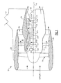
- Figure 1 illustrates a schematic view of selected portions of an example turbine engine 10, which serves as an exemplary operating environment for a rotatable component 50 ( Figure 2 ).
- the rotatable component is not limited to use in turbine engines and that other machinery will also benefit from this disclosure.
- the rotatable component 50 includes features for controlling load transfer there through, which allows the load path to be shifted away from perimeter areas that are sensitive to stress-concentrators. The control over load transfer thereby enables the use of bonded interfaces in rotatable components over mechanical interlock designs.
- the turbine engine 10 is a high bypass, geared turbofan arrangement, although the examples herein can also be applied in other engine configurations.
- the bypass ratio is greater than 10:1
- the fan 14 diameter is substantially larger than the diameter of the low pressure compressor 16a and the low pressure turbine 20a has a pressure ratio that is greater than 5:1.
- the gear train 24 can be any known suitable gear system, such as a planetary gear system with orbiting planet gears, planetary system with non-orbiting planet gears, or other type of gear system.
- the gear train 24 has a constant gear ratio. It is to be appreciated that the illustrated engine configuration and parameters are only exemplary and that the examples disclosed herein are applicable to other turbine engine configurations, including ground-based turbines that do not have fans.
- FIG. 2 shows an example of the rotatable component 50.
- the rotatable component 50 includes a first section 52 and a second section 54 that is located radially outwards of the first section 52 with regard to the axis A about which the sections 52 and 54 co-rotate during operation.
- the rotatable component 50 is a bladed turbine disk.
- the first section 52 is a disk (shown in part) and the second section 54 includes an airfoil blade B.
- the bladed turbine disk includes a plurality of first sections 52 and corresponding second sections 54 circumferentially arranged about axis A.
- the airfoil blade B has a wing-like shape that provides a lift force via Bernoulli's principle such that one side of the blade is a suction side and the other side of the airfoil is a pressure side.
- the first section 52 and the second section 54 are attached together at a bonded interface 56, which is shown in a sectional view in Figure 3 .
- the bonded interface 56 is substantially planar and includes an interior region 58 and a perimeter region 60 that extends around the periphery of the bonded interface 56.
- the first section 52 includes a perimeter portion 52a and the second section 54 includes a perimeter portion 54a.
- the radial surfaces of the perimeter portions 52a and 54a are bonded together at the perimeter region 60 of the bonded interface 56.
- the geometry of the perimeter portions 52a and 54a controls, at least on part, the difference in stiffness between the perimeter portions 52a and 54a.
- the perimeter portion 52a of the first section 52 includes a flange 52b that extends between a base 62a and a free end 62b.
- the perimeter portion 54a of the second section 54 includes another flange 54b that extends between a base 64a and a free end 64b.
- the flanges 52b and 54b in this example extend completely around the respective sections 52 and 54.
- the flange 52b can alternatively have a different shape than the illustrated shape with the undercut 68 to achieve the non-uniform radial thickness and desired stiffness.
- a ratio of R min /R max (R min divided by R max ) is 0.25 to 0.75 to effectively decrease the stiffness of the flange 52b.
- the ratio is greater than 0.5 in the given range.
- the surface S serves as a bonding surface for attachment to a new second section 154' to provide rotatable component 150'.
- the new second section 154' includes a new airfoil blade B'.
- the new second section 154' may be sized to account for the distance D such that the airfoil blade B is properly positioned.
- Figure 7 shows another embodiment of a rotatable component 250 that includes a damper element 80 located radially inwards of the flange 252b of the first component 252 and in contact with the distal portion 266b of the flange 252b.
- the damper element 80 optionally is also in contact with the distal portion 266b of a neighboring flange 252b of a first section 252.
- the damper element 80 serves a dual purpose of controlling vibration and frequency tuning of the blades of the second sections 254 and increasing bending mass of the flanges 252b to further reduce tensile loads in the perimeter region 56.
Landscapes
- Engineering & Computer Science (AREA)
- Mechanical Engineering (AREA)
- General Engineering & Computer Science (AREA)
- Chemical & Material Sciences (AREA)
- Materials Engineering (AREA)
- Structures Of Non-Positive Displacement Pumps (AREA)
- Turbine Rotor Nozzle Sealing (AREA)
- Pressure Welding/Diffusion-Bonding (AREA)
- Motorcycle And Bicycle Frame (AREA)
- Tires In General (AREA)
- Invalid Beds And Related Equipment (AREA)
Abstract
Description
- Rotatable components are known and used in machinery, such as gas turbine engines. For example, a typical gas turbine engine includes blades that are mounted for rotation on a disk. The blades include a keyed root that mechanically interlocks with a corresponding receiver on the disk. Such a configuration permits the blades to be relatively easily slid into or out of the disk for installation or maintenance.
- Disclosed is a rotatable component that includes a first section and a second section that is located radially outwards of the first section with regard to an axis of rotation about which the sections are co-rotatable. The sections are attached together at a bonded interface. At a perimeter region of the bonded interface, a perimeter portion of the first section has a first stiffness and a perimeter portion of the second section has a second stiffness that is greater than the first stiffness.
- In one aspect, the rotatable component is within a turbine engine that includes a compressor section, a combustor that is in fluid communication with the compressor section, and a turbine section that is in fluid communication the combustor. At least one of the compressor section and the turbine section includes the rotatable component.
- Also disclosed is a method for controlling a load between bonded sections of a rotatable component. The method includes bonding a first section and a second section together at a bonded interface such that the second section is located radially outwards of the first section with regard to an axis of rotation about which the first section and the second section are co-rotatable. Each of the first section and the second section has respective perimeter portions at a perimeter region of the bonded interface. The perimeter portion of the first section has a first stiffness and the perimeter portion of the second section has a second stiffness that is greater than the first stiffness. Upon co-rotation of the first section and the second section, there is a greater centrifugal pull on the perimeter portion of the first section than on the perimeter portion of the second section to reduce a tensile load on the bonded interface in the perimeter region.
- The various features and advantages of the disclosed examples will become apparent to those skilled in the art from the following detailed description. The drawings that accompany the detailed description can be briefly described as follows.
-
Figure 1 shows an example turbine engine. -
Figure 2 shows an example rotatable component. -
Figure 3 shows a bonded interface if a rotatable component. -
Figure 4 shows a section view of the rotatable component ofFigure 2 . -
Figure 5 shows a section view of a rotatable component during operation. -
Figure 6A shows another example rotatable component. -
Figure 6B shows a rotatable component with a section removed. -
Figure 6C shows a rotatable component with a new section in place of a removed section. -
Figure 7 shows a rotatable component with a damper element. -
Figure 1 illustrates a schematic view of selected portions of anexample turbine engine 10, which serves as an exemplary operating environment for a rotatable component 50 (Figure 2 ). It will be appreciated that the rotatable component is not limited to use in turbine engines and that other machinery will also benefit from this disclosure. As will be described in further detail, therotatable component 50 includes features for controlling load transfer there through, which allows the load path to be shifted away from perimeter areas that are sensitive to stress-concentrators. The control over load transfer thereby enables the use of bonded interfaces in rotatable components over mechanical interlock designs. - In the illustrated example, the
turbine engine 10 is suspended from anengine pylon 12 of an aircraft, as is typical of an aircraft designed for subsonic operation. Theturbine engine 10 is circumferentially disposed about an engine centerline, or axial centerline axis A. Theturbine engine 10 includes afan 14, acompressor 16 having a lowpressure compressor section 16a and a highpressure compressor section 16b, acombustion section 18, and aturbine 20 having a highpressure turbine section 20b and a lowpressure turbine section 20a. - As is known, air compressed in the
compressors combustion section 18 and expanded in theturbines turbines rotors compressors fan 14 in response to the expansion. In this example, therotor 22a drives thefan 14 through agear train 24. - In the example shown, the
turbine engine 10 is a high bypass, geared turbofan arrangement, although the examples herein can also be applied in other engine configurations. In a further example, the bypass ratio is greater than 10:1, thefan 14 diameter is substantially larger than the diameter of thelow pressure compressor 16a and thelow pressure turbine 20a has a pressure ratio that is greater than 5:1. Thegear train 24 can be any known suitable gear system, such as a planetary gear system with orbiting planet gears, planetary system with non-orbiting planet gears, or other type of gear system. In the disclosed example, thegear train 24 has a constant gear ratio. It is to be appreciated that the illustrated engine configuration and parameters are only exemplary and that the examples disclosed herein are applicable to other turbine engine configurations, including ground-based turbines that do not have fans. - An outer housing,
nacelle 28, (also commonly referred to as a fan nacelle) extends circumferentially about thefan 14. A generally annularfan bypass passage 30 extends between thenacelle 28 and an inner housing,inner cowl 34, which generally surrounds thecompressors turbines turbine engine 10 also includes guide vanes 29 (shown schematically). - In operation, the
fan 14 draws air into theturbine engine 10 as a core flow, C, and into thebypass passage 30 as a bypass air flow, D. In one example, approximately 80 percent of the airflow entering thenacelle 28 becomes bypass airflow D. Arear exhaust 36 discharges the bypass air flow D from theturbine engine 10. The core flow C is discharged from a passage between theinner cowl 34 and atail cone 38. A significant amount of thrust may be provided by the bypass airflow D due to the high bypass ratio. - As can be appreciated, the
turbine engine 10 may include rotatable components in one or more of the sections of the engine, such as thefan 14, the lowpressure compressor section 16a, the highpressure compressor section 16b, the highpressure turbine section 20b and the lowpressure turbine section 20a. -
Figure 2 shows an example of therotatable component 50. Therotatable component 50 includes afirst section 52 and asecond section 54 that is located radially outwards of thefirst section 52 with regard to the axis A about which thesections turbine engine 10, therotatable component 50 is a bladed turbine disk. Thefirst section 52 is a disk (shown in part) and thesecond section 54 includes an airfoil blade B. The bladed turbine disk includes a plurality offirst sections 52 and correspondingsecond sections 54 circumferentially arranged about axis A. In general, the airfoil blade B has a wing-like shape that provides a lift force via Bernoulli's principle such that one side of the blade is a suction side and the other side of the airfoil is a pressure side. - The
first section 52 and thesecond section 54 are attached together at abonded interface 56, which is shown in a sectional view inFigure 3 . In this example, thebonded interface 56 is substantially planar and includes aninterior region 58 and aperimeter region 60 that extends around the periphery of thebonded interface 56. - The
first section 52 is bonded to thesecond section 54 entirely across thebonded interface 56. For example, thebonded interface 56 is the product of diffusion bonding, brazing, linear friction welding, inertial bonding or other type of component-to-component bonding process. In the illustrated example, thesections sections - At the
perimeter region 60 of the bondedinterface 56, thefirst section 52 includes aperimeter portion 52a and thesecond section 54 includes aperimeter portion 54a. The radial surfaces of theperimeter portions perimeter region 60 of the bondedinterface 56. - The
perimeter portion 52a has a first stiffness and theperimeter portion 54a has a second stiffness that is greater than the first stiffness. For example, the stiffness is a function of the respective geometries of theperimeter portions perimeter portions interface 56 during operation of therotatable component 50. - In one example, the geometry of the
perimeter portions perimeter portions perimeter portion 52a of thefirst section 52 includes aflange 52b that extends between abase 62a and afree end 62b. Theperimeter portion 54a of thesecond section 54 includes anotherflange 54b that extends between abase 64a and afree end 64b. Although shown in two dimensions inFigure 2 , it is to be understood that theflanges respective sections - Referring to
Figure 4 , theflange 52b of thefirst section 52 includes aproximal portion 66a and adistal portion 66b with regard to proximity to thebase 62a. In this example, thedistal portion 66b is radially larger than theproximal portion 66a. As shown, theproximal portion 66a is formed with an undercut 68 to provide thedistal portion 66b with a maximum radial dimension 70 (Rmax) and theproximal portion 66a with a minimum radial dimension 72 (Rmin). Thus, theflange 52b has a non-uniform radial thickness, which controls the stiffness. It is to be understood that theflange 52b can alternatively have a different shape than the illustrated shape with the undercut 68 to achieve the non-uniform radial thickness and desired stiffness. In one example, a ratio of Rmin/Rmax (Rmin divided by Rmax) is 0.25 to 0.75 to effectively decrease the stiffness of theflange 52b. In a further example, the ratio is greater than 0.5 in the given range. - As shown the section view of
Figure 5 , the difference between the stiffness of theflange 52b and the stiffness of theflange 54b causes a greater centrifugal pull P on theflange 52b than on theflange 54b during operation (i.e., rotation) of therotatable component 50. Thus, a potential amount of deflection of theflange 52b exceeds the actual amount of deflection of theflange 54b. The result is that theflange 52b tends to deflect against theflange 54b and thereby reduces a tensile load on the bondedinterface 56 in theperimeter region 60. In some examples, there is a compressive load in theperimeter region 60. The reduction in the tensile load has the effect of distributing or focusing the tensile load (due to centrifugal forces) across the bondedinterface 56 to theinterior region 58. The reduction in tensile load in theperimeter region 60 makes therotatable component 50 less sensitive to the effects of any imperfections or other stress concentrators in theperimeter region 60. The reduced sensitivity to imperfections and other stress concentrators in theperimeter region 60 thereby permits the bondedinterface 56 to be used in therotational component 50 to replace mechanical interlock designs, for example. - As shown in
Figures 6A, 6B and 6C , the methodology for controlling the load is also applicable to maintenance circumstances.Figure 6A shows arotatable component 150 that includes afirst section 152 and asecond section 154 that are attached together at bondedinterface 156. In this disclosure, like reference numerals designate like elements where appropriate and reference numerals with the addition of one-hundred, multiples thereof or a prime (') designate modified elements that are understood to incorporate the same features and benefits of the corresponding elements. - The
second section 154 includes an airfoil blade B that is removed because of damage during use, for example. As shown inFigure 6B , a substantial portion of thesecond section 154, including the airfoil blade B, is removed by cutting or the like at surface S along a line L. As shown inFigure 6C , the line L is spaced a distance D from the plane of the bondedinterface 156. Alternatively, the surface S is cut lower such that the bondedinterface 156 is removed with thesecond section 154. - The surface S serves as a bonding surface for attachment to a new second section 154' to provide rotatable component 150'. Thus, the
first section 152 and any remaining portion of thesecond section 154 after removal in essence become a new first section 152' that is attached to the new second section 154' at bonded interface 156'. The new second section 154' includes a new airfoil blade B'. The new second section 154' may be sized to account for the distance D such that the airfoil blade B is properly positioned. -
Figure 7 shows another embodiment of arotatable component 250 that includes adamper element 80 located radially inwards of theflange 252b of thefirst component 252 and in contact with thedistal portion 266b of theflange 252b. As shown, thedamper element 80 optionally is also in contact with thedistal portion 266b of a neighboringflange 252b of afirst section 252. Thedamper element 80 serves a dual purpose of controlling vibration and frequency tuning of the blades of thesecond sections 254 and increasing bending mass of theflanges 252b to further reduce tensile loads in theperimeter region 56. - Although a combination of features is shown in the illustrated examples, not all of them need to be combined to realize the benefits of various embodiments of this disclosure. In other words, a system designed according to an embodiment of this disclosure will not necessarily include all of the features shown in any one of the Figures or all of the portions schematically shown in the Figures. Moreover, selected features of one example embodiment may be combined with selected features of other example embodiments.
- The preceding description is exemplary rather than limiting in nature. Variations and modifications to the disclosed examples may become apparent to those skilled in the art that do not necessarily depart from the essence of this disclosure. The scope of legal protection given to this disclosure can only be determined by studying the following claims.
Claims (15)
- A rotatable component (50) comprising:a first section (52);a second section (54) located radially outwards of the first section (52) with regard to an axis of rotation (A) about which the first section (52) and the second section (54) are co-rotatable; anda bonded interface (56) at which the first section (52) and the second section (54) are attached together, wherein, at a perimeter region (60) of the bonded interface (56), a perimeter portion (52a) of the first section (52) has a first stiffness and a perimeter portion (54a) of the second section (54) has a second stiffness that is greater than the first stiffness.
- The rotatable component (50) as recited in claim 1, wherein the perimeter portion (52a) of the first section (52) comprises a flange (52b) extending between a base (62a) and a free end (62b), the perimeter portion (54a) of the second section (54) comprises another flange (54b) extending between a base (64a) and a free end (64b), the flange (52b) of the first section (52) including a proximal portion (66a) and a distal portion (66b) with regard to proximity to its base (62a), and the distal portion (66b) is radially larger than the proximal portion (66a).
- The rotatable component (50) as recited in claim 2, wherein the distal portion (66b) includes a maximum radial dimension (Rmax) (72) and the proximal portion (66a) includes a minimum radial dimension (Rmin) (70), and a ratio of Rmin/Rmax (Rmin divided by Rmax) is 0.25 to 0.75, and optionally at least 0.5.
- The rotatable component (250) as recited in claim 2 or 3, including a damper element (80) located radially inwards of the flange (252b) of the first section (252) and in contact with the distal portion (266b) of the flange of the first section (252).
- The rotatable component (50) as recited in any preceding claim, wherein the perimeter portion (52a) of the first section (52) comprises a flange (52b) extending between a base (62a) and a free end (62b), the perimeter portion (54a) of the second section (54) comprises another flange (54b) extending between a base (64a) and a free end (64b), and the radial thickness of the flange (52b) of the first section (52) is non-uniform.
- The rotatable component (50) as recited in any preceding claim, wherein the perimeter portion (52a) of the first section (52) comprises a flange (52b) extending between a base (62a) and a free end (62b), the perimeter portion (54a) of the second section (54) comprises another flange (54b) extending between a base (64a) and a free end (64b), and the flange (52b) of the first section (52) includes an undercut (68).
- The rotatable component (50) as recited in any preceding claim, wherein the first section (52) and the second section (54) comprise materials having the same chemical composition.
- The rotatable component (50) as recited in claim 7, wherein the materials are a nickel alloy.
- The rotatable component (50) as recited in any preceding claim, wherein the bonded interface (56) is planar.
- The rotatable component (50) as recited in any preceding claim, wherein the rotatable component (50) is a bladed disk.
- The rotatable component (50) as recited in any preceding claim, wherein the second section (54) includes an airfoil blade (B).
- A turbine engine (10) comprising:a compressor section (16);a combustor (18) in fluid communication with the compressor section; anda turbine section (20) in fluid communication with the combustor, wherein at least one of the compressor section (16) and the turbine section (20) includes a rotatable component (50) as claimed in any preceding claim.
- A method for controlling a load between bonded sections (52, 54) of a rotatable component (50), the method comprising:bonding a first section (52) and a second section (54) together at a bonded interface (56) such that the second section (54) is located radially outwards of the first section (54) with regard to an axis of rotation (A) about which the first section (52) and the second section (54) are co-rotatable;at a perimeter region (60) of the bonded interface (56), establishing a perimeter portion (52a) of the first section (52) to have a first stiffness and a perimeter portion (54a) of the second section (54) to have a second stiffness that is greater than the first stiffness such that, upon co-rotation of the first section (52) and the second section (54), there is greater centrifugal pull on the perimeter portion (54a) of first section (52) than on the perimeter portion (54a) of second section (54) to reduce a tensile load on the bonded interface (56) in the perimeter region (60).
- The method as recited in claim 13, including establishing the first stiffness by providing the perimeter portion (52a) of the first section (52) with a flange (52b):including an undercut (68); and/orof non-uniform radial thickness; and/orincluding a radially enlarged end portion (62b).
- The method as recited in claim 13 or 14, wherein the second section (154') includes an airfoil blade (B) and, prior to the bonding of the first section (152') and the second section (154'), a prior airfoil blade (154) is removed from the first section (152'), and optionally including locating the bonded interface (156') a distance (D) from a preexisting bonded interface (156) between the prior airfoil blade (154) and the first section (152').
Applications Claiming Priority (1)
| Application Number | Priority Date | Filing Date | Title |
|---|---|---|---|
| US13/289,161 US9121296B2 (en) | 2011-11-04 | 2011-11-04 | Rotatable component with controlled load interface |
Publications (3)
| Publication Number | Publication Date |
|---|---|
| EP2589755A2 true EP2589755A2 (en) | 2013-05-08 |
| EP2589755A3 EP2589755A3 (en) | 2017-01-25 |
| EP2589755B1 EP2589755B1 (en) | 2020-01-01 |
Family
ID=47227480
Family Applications (1)
| Application Number | Title | Priority Date | Filing Date |
|---|---|---|---|
| EP12190940.2A Active EP2589755B1 (en) | 2011-11-04 | 2012-11-01 | Rotatable component of a gas turbine with controlled load interface and corresponding method |
Country Status (2)
| Country | Link |
|---|---|
| US (1) | US9121296B2 (en) |
| EP (1) | EP2589755B1 (en) |
Cited By (4)
| Publication number | Priority date | Publication date | Assignee | Title |
|---|---|---|---|---|
| CN106155639A (en) * | 2015-03-24 | 2016-11-23 | 阿里巴巴集团控股有限公司 | A kind of loading method operating interface and device |
| EP3052763A4 (en) * | 2013-09-30 | 2017-06-14 | United Technologies Corporation | A nonmetallic airfoil with a compliant attachment |
| EP3238868A1 (en) * | 2016-04-27 | 2017-11-01 | MTU Aero Engines GmbH | Method for producing a rotor blade for a fluid flow engine |
| CN108680322A (en) * | 2018-03-29 | 2018-10-19 | 合肥通用机械研究院有限公司 | A kind of centrifugal impeller vibration damping test system and method |
Families Citing this family (2)
| Publication number | Priority date | Publication date | Assignee | Title |
|---|---|---|---|---|
| US20190040749A1 (en) * | 2017-08-01 | 2019-02-07 | United Technologies Corporation | Method of fabricating a turbine blade |
| US12196107B2 (en) | 2023-02-22 | 2025-01-14 | General Electric Company | Turbine engine with a blade having woven core and toughened region |
Family Cites Families (9)
| Publication number | Priority date | Publication date | Assignee | Title |
|---|---|---|---|---|
| GB1064399A (en) * | 1964-12-30 | 1967-04-05 | Rover Co Ltd | Welded turbine or compressor rotor |
| US6183202B1 (en) | 1999-04-30 | 2001-02-06 | General Electric Company | Stress relieved blade support |
| US6666653B1 (en) * | 2002-05-30 | 2003-12-23 | General Electric Company | Inertia welding of blades to rotors |
| US6969238B2 (en) * | 2003-10-21 | 2005-11-29 | General Electric Company | Tri-property rotor assembly of a turbine engine, and method for its preparation |
| US7153102B2 (en) | 2004-05-14 | 2006-12-26 | Pratt & Whitney Canada Corp. | Bladed disk fixing undercut |
| GB0615671D0 (en) * | 2006-08-08 | 2006-09-13 | Rolls Royce Plc | A method of friction welding |
| US7766623B2 (en) * | 2006-11-08 | 2010-08-03 | General Electric Company | System for manufacturing a rotor having an MMC ring component and an airfoil component having monolithic airfoils |
| US20090304514A1 (en) * | 2007-10-09 | 2009-12-10 | Hamilton Sundstrand Corporation | Method of manufacturing a turbine rotor |
| US8066479B2 (en) * | 2010-04-05 | 2011-11-29 | Pratt & Whitney Rocketdyne, Inc. | Non-integral platform and damper for an airfoil |
-
2011
- 2011-11-04 US US13/289,161 patent/US9121296B2/en active Active
-
2012
- 2012-11-01 EP EP12190940.2A patent/EP2589755B1/en active Active
Non-Patent Citations (1)
| Title |
|---|
| None |
Cited By (8)
| Publication number | Priority date | Publication date | Assignee | Title |
|---|---|---|---|---|
| EP3052763A4 (en) * | 2013-09-30 | 2017-06-14 | United Technologies Corporation | A nonmetallic airfoil with a compliant attachment |
| US10280769B2 (en) | 2013-09-30 | 2019-05-07 | United Technologies Corporation | Nonmetallic airfoil with a compliant attachment |
| CN106155639A (en) * | 2015-03-24 | 2016-11-23 | 阿里巴巴集团控股有限公司 | A kind of loading method operating interface and device |
| CN106155639B (en) * | 2015-03-24 | 2020-02-07 | 阿里巴巴集团控股有限公司 | Operation interface loading method and device |
| EP3238868A1 (en) * | 2016-04-27 | 2017-11-01 | MTU Aero Engines GmbH | Method for producing a rotor blade for a fluid flow engine |
| US10526902B2 (en) | 2016-04-27 | 2020-01-07 | MTU Aero Engines AG | Method for producing a blade for a turbomachine |
| CN108680322A (en) * | 2018-03-29 | 2018-10-19 | 合肥通用机械研究院有限公司 | A kind of centrifugal impeller vibration damping test system and method |
| CN108680322B (en) * | 2018-03-29 | 2020-07-07 | 合肥通用机械研究院有限公司 | Centrifugal impeller vibration damping test system and method |
Also Published As
| Publication number | Publication date |
|---|---|
| EP2589755B1 (en) | 2020-01-01 |
| US9121296B2 (en) | 2015-09-01 |
| US20130115089A1 (en) | 2013-05-09 |
| EP2589755A3 (en) | 2017-01-25 |
Similar Documents
| Publication | Publication Date | Title |
|---|---|---|
| EP3000979B1 (en) | Clamped vane arc segment having load-transmitting features | |
| US20190316488A1 (en) | Gas turbine engine | |
| EP2589755B1 (en) | Rotatable component of a gas turbine with controlled load interface and corresponding method | |
| US20220389875A1 (en) | Geared gas turbine engine | |
| US11515753B2 (en) | Reduction gearbox | |
| EP3667022B1 (en) | Ice crystal protection for a gas turbine engine | |
| EP3822452B1 (en) | Gas turbine engine | |
| EP3686561B1 (en) | Shaft monitoring system | |
| EP3611398B1 (en) | Stabilization bearing system for geared turbofan engines | |
| EP3686438B1 (en) | Fan blade | |
| EP3699406A1 (en) | Component for fastening arrangement, fastening arrangement and gas turbine engine comprising fastening arrangement | |
| US11131248B2 (en) | Planetary gear, splined sleeve, gas turbine engine with a planetary gear and method for manufacturing a planetary gear | |
| EP3708850B1 (en) | Core duct assembly for a gas turbine engine | |
| US10995676B2 (en) | Planetary gear device, gas turbine engine and method for manufacturing a planetary gear device | |
| US11066943B2 (en) | Intermediate casing for a compressor in a gas turbine engine and a gas turbine engine | |
| US12007010B2 (en) | Gear wheel of a transmission | |
| US20200003068A1 (en) | Gas turbine | |
| US11970981B2 (en) | Planetary gearbox | |
| EP3282101B1 (en) | Shim for gas turbine engine | |
| US11879383B2 (en) | Torque limiting device in a connection between a gearbox and a stationary structure in a gas turbine engine and a gas turbine engine | |
| EP4513000A1 (en) | Bathtub seal for damping cmc vane platform | |
| EP4517050A1 (en) | Cmc vane with rotatable baffle design to accommodate re-stagger | |
| US11060419B2 (en) | Planetary gear drive and aircraft gas turbine with a planetary gear drive | |
| EP3012411A1 (en) | Integrally bladed rotor having axial arm and pocket | |
| EP3819480A1 (en) | Bracket |
Legal Events
| Date | Code | Title | Description |
|---|---|---|---|
| PUAI | Public reference made under article 153(3) epc to a published international application that has entered the european phase |
Free format text: ORIGINAL CODE: 0009012 |
|
| AK | Designated contracting states |
Kind code of ref document: A2 Designated state(s): AL AT BE BG CH CY CZ DE DK EE ES FI FR GB GR HR HU IE IS IT LI LT LU LV MC MK MT NL NO PL PT RO RS SE SI SK SM TR |
|
| AX | Request for extension of the european patent |
Extension state: BA ME |
|
| RAP1 | Party data changed (applicant data changed or rights of an application transferred) |
Owner name: UNITED TECHNOLOGIES CORPORATION |
|
| PUAL | Search report despatched |
Free format text: ORIGINAL CODE: 0009013 |
|
| AK | Designated contracting states |
Kind code of ref document: A3 Designated state(s): AL AT BE BG CH CY CZ DE DK EE ES FI FR GB GR HR HU IE IS IT LI LT LU LV MC MK MT NL NO PL PT RO RS SE SI SK SM TR |
|
| AX | Request for extension of the european patent |
Extension state: BA ME |
|
| RIC1 | Information provided on ipc code assigned before grant |
Ipc: F01D 5/22 20060101ALI20161222BHEP Ipc: B23K 1/008 20060101ALI20161222BHEP Ipc: F01D 21/04 20060101ALI20161222BHEP Ipc: B23P 6/00 20060101ALI20161222BHEP Ipc: B23K 1/00 20060101ALI20161222BHEP Ipc: F01D 5/00 20060101ALI20161222BHEP Ipc: F01D 5/30 20060101AFI20161222BHEP |
|
| STAA | Information on the status of an ep patent application or granted ep patent |
Free format text: STATUS: REQUEST FOR EXAMINATION WAS MADE |
|
| 17P | Request for examination filed |
Effective date: 20170724 |
|
| RBV | Designated contracting states (corrected) |
Designated state(s): AL AT BE BG CH CY CZ DE DK EE ES FI FR GB GR HR HU IE IS IT LI LT LU LV MC MK MT NL NO PL PT RO RS SE SI SK SM TR |
|
| GRAJ | Information related to disapproval of communication of intention to grant by the applicant or resumption of examination proceedings by the epo deleted |
Free format text: ORIGINAL CODE: EPIDOSDIGR1 |
|
| GRAP | Despatch of communication of intention to grant a patent |
Free format text: ORIGINAL CODE: EPIDOSNIGR1 |
|
| RIC1 | Information provided on ipc code assigned before grant |
Ipc: B23K 1/00 20060101ALI20190225BHEP Ipc: F01D 21/04 20060101ALI20190225BHEP Ipc: B23K 101/00 20060101ALI20190225BHEP Ipc: F01D 5/00 20060101ALI20190225BHEP Ipc: B23K 20/00 20060101ALI20190225BHEP Ipc: B23K 20/02 20060101ALI20190225BHEP Ipc: B23K 1/008 20060101ALI20190225BHEP Ipc: B23K 1/19 20060101ALI20190225BHEP Ipc: B23K 20/12 20060101ALI20190225BHEP Ipc: B23P 6/00 20060101ALI20190225BHEP Ipc: B23K 103/00 20060101ALI20190225BHEP Ipc: B23K 20/233 20060101ALI20190225BHEP Ipc: F01D 5/30 20060101AFI20190225BHEP Ipc: F01D 5/22 20060101ALI20190225BHEP Ipc: B23K 103/18 20060101ALI20190225BHEP |
|
| GRAP | Despatch of communication of intention to grant a patent |
Free format text: ORIGINAL CODE: EPIDOSNIGR1 |
|
| STAA | Information on the status of an ep patent application or granted ep patent |
Free format text: STATUS: GRANT OF PATENT IS INTENDED |
|
| RIN1 | Information on inventor provided before grant (corrected) |
Inventor name: MCCAFFREY, MICHAEL G. |
|
| INTG | Intention to grant announced |
Effective date: 20190520 |
|
| GRAS | Grant fee paid |
Free format text: ORIGINAL CODE: EPIDOSNIGR3 |
|
| GRAA | (expected) grant |
Free format text: ORIGINAL CODE: 0009210 |
|
| STAA | Information on the status of an ep patent application or granted ep patent |
Free format text: STATUS: THE PATENT HAS BEEN GRANTED |
|
| AK | Designated contracting states |
Kind code of ref document: B1 Designated state(s): AL AT BE BG CH CY CZ DE DK EE ES FI FR GB GR HR HU IE IS IT LI LT LU LV MC MK MT NL NO PL PT RO RS SE SI SK SM TR |
|
| REG | Reference to a national code |
Ref country code: GB Ref legal event code: FG4D |
|
| REG | Reference to a national code |
Ref country code: CH Ref legal event code: EP Ref country code: AT Ref legal event code: REF Ref document number: 1220024 Country of ref document: AT Kind code of ref document: T Effective date: 20200115 |
|
| REG | Reference to a national code |
Ref country code: IE Ref legal event code: FG4D |
|
| REG | Reference to a national code |
Ref country code: DE Ref legal event code: R096 Ref document number: 602012066859 Country of ref document: DE |
|
| REG | Reference to a national code |
Ref country code: NL Ref legal event code: MP Effective date: 20200101 |
|
| REG | Reference to a national code |
Ref country code: LT Ref legal event code: MG4D |
|
| PG25 | Lapsed in a contracting state [announced via postgrant information from national office to epo] |
Ref country code: NL Free format text: LAPSE BECAUSE OF FAILURE TO SUBMIT A TRANSLATION OF THE DESCRIPTION OR TO PAY THE FEE WITHIN THE PRESCRIBED TIME-LIMIT Effective date: 20200101 Ref country code: RS Free format text: LAPSE BECAUSE OF FAILURE TO SUBMIT A TRANSLATION OF THE DESCRIPTION OR TO PAY THE FEE WITHIN THE PRESCRIBED TIME-LIMIT Effective date: 20200101 Ref country code: FI Free format text: LAPSE BECAUSE OF FAILURE TO SUBMIT A TRANSLATION OF THE DESCRIPTION OR TO PAY THE FEE WITHIN THE PRESCRIBED TIME-LIMIT Effective date: 20200101 Ref country code: CZ Free format text: LAPSE BECAUSE OF FAILURE TO SUBMIT A TRANSLATION OF THE DESCRIPTION OR TO PAY THE FEE WITHIN THE PRESCRIBED TIME-LIMIT Effective date: 20200101 Ref country code: PT Free format text: LAPSE BECAUSE OF FAILURE TO SUBMIT A TRANSLATION OF THE DESCRIPTION OR TO PAY THE FEE WITHIN THE PRESCRIBED TIME-LIMIT Effective date: 20200527 Ref country code: NO Free format text: LAPSE BECAUSE OF FAILURE TO SUBMIT A TRANSLATION OF THE DESCRIPTION OR TO PAY THE FEE WITHIN THE PRESCRIBED TIME-LIMIT Effective date: 20200401 Ref country code: LT Free format text: LAPSE BECAUSE OF FAILURE TO SUBMIT A TRANSLATION OF THE DESCRIPTION OR TO PAY THE FEE WITHIN THE PRESCRIBED TIME-LIMIT Effective date: 20200101 |
|
| PG25 | Lapsed in a contracting state [announced via postgrant information from national office to epo] |
Ref country code: LV Free format text: LAPSE BECAUSE OF FAILURE TO SUBMIT A TRANSLATION OF THE DESCRIPTION OR TO PAY THE FEE WITHIN THE PRESCRIBED TIME-LIMIT Effective date: 20200101 Ref country code: SE Free format text: LAPSE BECAUSE OF FAILURE TO SUBMIT A TRANSLATION OF THE DESCRIPTION OR TO PAY THE FEE WITHIN THE PRESCRIBED TIME-LIMIT Effective date: 20200101 Ref country code: BG Free format text: LAPSE BECAUSE OF FAILURE TO SUBMIT A TRANSLATION OF THE DESCRIPTION OR TO PAY THE FEE WITHIN THE PRESCRIBED TIME-LIMIT Effective date: 20200401 Ref country code: GR Free format text: LAPSE BECAUSE OF FAILURE TO SUBMIT A TRANSLATION OF THE DESCRIPTION OR TO PAY THE FEE WITHIN THE PRESCRIBED TIME-LIMIT Effective date: 20200402 Ref country code: IS Free format text: LAPSE BECAUSE OF FAILURE TO SUBMIT A TRANSLATION OF THE DESCRIPTION OR TO PAY THE FEE WITHIN THE PRESCRIBED TIME-LIMIT Effective date: 20200501 Ref country code: HR Free format text: LAPSE BECAUSE OF FAILURE TO SUBMIT A TRANSLATION OF THE DESCRIPTION OR TO PAY THE FEE WITHIN THE PRESCRIBED TIME-LIMIT Effective date: 20200101 |
|
| REG | Reference to a national code |
Ref country code: DE Ref legal event code: R097 Ref document number: 602012066859 Country of ref document: DE |
|
| PG25 | Lapsed in a contracting state [announced via postgrant information from national office to epo] |
Ref country code: EE Free format text: LAPSE BECAUSE OF FAILURE TO SUBMIT A TRANSLATION OF THE DESCRIPTION OR TO PAY THE FEE WITHIN THE PRESCRIBED TIME-LIMIT Effective date: 20200101 Ref country code: SM Free format text: LAPSE BECAUSE OF FAILURE TO SUBMIT A TRANSLATION OF THE DESCRIPTION OR TO PAY THE FEE WITHIN THE PRESCRIBED TIME-LIMIT Effective date: 20200101 Ref country code: SK Free format text: LAPSE BECAUSE OF FAILURE TO SUBMIT A TRANSLATION OF THE DESCRIPTION OR TO PAY THE FEE WITHIN THE PRESCRIBED TIME-LIMIT Effective date: 20200101 Ref country code: DK Free format text: LAPSE BECAUSE OF FAILURE TO SUBMIT A TRANSLATION OF THE DESCRIPTION OR TO PAY THE FEE WITHIN THE PRESCRIBED TIME-LIMIT Effective date: 20200101 Ref country code: RO Free format text: LAPSE BECAUSE OF FAILURE TO SUBMIT A TRANSLATION OF THE DESCRIPTION OR TO PAY THE FEE WITHIN THE PRESCRIBED TIME-LIMIT Effective date: 20200101 Ref country code: ES Free format text: LAPSE BECAUSE OF FAILURE TO SUBMIT A TRANSLATION OF THE DESCRIPTION OR TO PAY THE FEE WITHIN THE PRESCRIBED TIME-LIMIT Effective date: 20200101 |
|
| PLBE | No opposition filed within time limit |
Free format text: ORIGINAL CODE: 0009261 |
|
| STAA | Information on the status of an ep patent application or granted ep patent |
Free format text: STATUS: NO OPPOSITION FILED WITHIN TIME LIMIT |
|
| REG | Reference to a national code |
Ref country code: AT Ref legal event code: MK05 Ref document number: 1220024 Country of ref document: AT Kind code of ref document: T Effective date: 20200101 |
|
| 26N | No opposition filed |
Effective date: 20201002 |
|
| PG25 | Lapsed in a contracting state [announced via postgrant information from national office to epo] |
Ref country code: AT Free format text: LAPSE BECAUSE OF FAILURE TO SUBMIT A TRANSLATION OF THE DESCRIPTION OR TO PAY THE FEE WITHIN THE PRESCRIBED TIME-LIMIT Effective date: 20200101 Ref country code: IT Free format text: LAPSE BECAUSE OF FAILURE TO SUBMIT A TRANSLATION OF THE DESCRIPTION OR TO PAY THE FEE WITHIN THE PRESCRIBED TIME-LIMIT Effective date: 20200101 |
|
| PG25 | Lapsed in a contracting state [announced via postgrant information from national office to epo] |
Ref country code: SI Free format text: LAPSE BECAUSE OF FAILURE TO SUBMIT A TRANSLATION OF THE DESCRIPTION OR TO PAY THE FEE WITHIN THE PRESCRIBED TIME-LIMIT Effective date: 20200101 Ref country code: PL Free format text: LAPSE BECAUSE OF FAILURE TO SUBMIT A TRANSLATION OF THE DESCRIPTION OR TO PAY THE FEE WITHIN THE PRESCRIBED TIME-LIMIT Effective date: 20200101 |
|
| PG25 | Lapsed in a contracting state [announced via postgrant information from national office to epo] |
Ref country code: MC Free format text: LAPSE BECAUSE OF FAILURE TO SUBMIT A TRANSLATION OF THE DESCRIPTION OR TO PAY THE FEE WITHIN THE PRESCRIBED TIME-LIMIT Effective date: 20200101 |
|
| REG | Reference to a national code |
Ref country code: CH Ref legal event code: PL |
|
| PG25 | Lapsed in a contracting state [announced via postgrant information from national office to epo] |
Ref country code: LU Free format text: LAPSE BECAUSE OF NON-PAYMENT OF DUE FEES Effective date: 20201101 |
|
| REG | Reference to a national code |
Ref country code: BE Ref legal event code: MM Effective date: 20201130 |
|
| PG25 | Lapsed in a contracting state [announced via postgrant information from national office to epo] |
Ref country code: CH Free format text: LAPSE BECAUSE OF NON-PAYMENT OF DUE FEES Effective date: 20201130 Ref country code: LI Free format text: LAPSE BECAUSE OF NON-PAYMENT OF DUE FEES Effective date: 20201130 |
|
| PG25 | Lapsed in a contracting state [announced via postgrant information from national office to epo] |
Ref country code: IE Free format text: LAPSE BECAUSE OF NON-PAYMENT OF DUE FEES Effective date: 20201101 |
|
| PG25 | Lapsed in a contracting state [announced via postgrant information from national office to epo] |
Ref country code: TR Free format text: LAPSE BECAUSE OF FAILURE TO SUBMIT A TRANSLATION OF THE DESCRIPTION OR TO PAY THE FEE WITHIN THE PRESCRIBED TIME-LIMIT Effective date: 20200101 Ref country code: MT Free format text: LAPSE BECAUSE OF FAILURE TO SUBMIT A TRANSLATION OF THE DESCRIPTION OR TO PAY THE FEE WITHIN THE PRESCRIBED TIME-LIMIT Effective date: 20200101 Ref country code: CY Free format text: LAPSE BECAUSE OF FAILURE TO SUBMIT A TRANSLATION OF THE DESCRIPTION OR TO PAY THE FEE WITHIN THE PRESCRIBED TIME-LIMIT Effective date: 20200101 |
|
| PG25 | Lapsed in a contracting state [announced via postgrant information from national office to epo] |
Ref country code: MK Free format text: LAPSE BECAUSE OF FAILURE TO SUBMIT A TRANSLATION OF THE DESCRIPTION OR TO PAY THE FEE WITHIN THE PRESCRIBED TIME-LIMIT Effective date: 20200101 Ref country code: AL Free format text: LAPSE BECAUSE OF FAILURE TO SUBMIT A TRANSLATION OF THE DESCRIPTION OR TO PAY THE FEE WITHIN THE PRESCRIBED TIME-LIMIT Effective date: 20200101 |
|
| PG25 | Lapsed in a contracting state [announced via postgrant information from national office to epo] |
Ref country code: BE Free format text: LAPSE BECAUSE OF NON-PAYMENT OF DUE FEES Effective date: 20201130 |
|
| REG | Reference to a national code |
Ref country code: DE Ref legal event code: R081 Ref document number: 602012066859 Country of ref document: DE Owner name: RAYTHEON TECHNOLOGIES CORPORATION (N.D.GES.D.S, US Free format text: FORMER OWNER: UNITED TECHNOLOGIES CORPORATION, FARMINGTON, CONN., US |
|
| P01 | Opt-out of the competence of the unified patent court (upc) registered |
Effective date: 20230520 |
|
| PGFP | Annual fee paid to national office [announced via postgrant information from national office to epo] |
Ref country code: DE Payment date: 20241022 Year of fee payment: 13 |
|
| PGFP | Annual fee paid to national office [announced via postgrant information from national office to epo] |
Ref country code: GB Payment date: 20241023 Year of fee payment: 13 |
|
| PGFP | Annual fee paid to national office [announced via postgrant information from national office to epo] |
Ref country code: FR Payment date: 20241022 Year of fee payment: 13 |