EP2589731B1 - Button lock - Google Patents
Button lock Download PDFInfo
- Publication number
- EP2589731B1 EP2589731B1 EP11789382.6A EP11789382A EP2589731B1 EP 2589731 B1 EP2589731 B1 EP 2589731B1 EP 11789382 A EP11789382 A EP 11789382A EP 2589731 B1 EP2589731 B1 EP 2589731B1
- Authority
- EP
- European Patent Office
- Prior art keywords
- lock
- plate
- pin
- reset
- push button
- Prior art date
- Legal status (The legal status is an assumption and is not a legal conclusion. Google has not performed a legal analysis and makes no representation as to the accuracy of the status listed.)
- Active
Links
Images











Classifications
-
- E—FIXED CONSTRUCTIONS
- E05—LOCKS; KEYS; WINDOW OR DOOR FITTINGS; SAFES
- E05B—LOCKS; ACCESSORIES THEREFOR; HANDCUFFS
- E05B37/00—Permutation or combination locks; Puzzle locks
- E05B37/16—Permutation or combination locks; Puzzle locks with two or more push or pull knobs, slides, or the like
-
- E—FIXED CONSTRUCTIONS
- E05—LOCKS; KEYS; WINDOW OR DOOR FITTINGS; SAFES
- E05B—LOCKS; ACCESSORIES THEREFOR; HANDCUFFS
- E05B63/00—Locks or fastenings with special structural characteristics
- E05B63/0056—Locks with adjustable or exchangeable lock parts
-
- Y—GENERAL TAGGING OF NEW TECHNOLOGICAL DEVELOPMENTS; GENERAL TAGGING OF CROSS-SECTIONAL TECHNOLOGIES SPANNING OVER SEVERAL SECTIONS OF THE IPC; TECHNICAL SUBJECTS COVERED BY FORMER USPC CROSS-REFERENCE ART COLLECTIONS [XRACs] AND DIGESTS
- Y10—TECHNICAL SUBJECTS COVERED BY FORMER USPC
- Y10T—TECHNICAL SUBJECTS COVERED BY FORMER US CLASSIFICATION
- Y10T70/00—Locks
- Y10T70/50—Special application
- Y10T70/5611—For control and machine elements
- Y10T70/5757—Handle, handwheel or knob
- Y10T70/5765—Rotary or swinging
- Y10T70/577—Locked stationary
- Y10T70/5783—Combination lock
- Y10T70/5788—Push pin or button
-
- Y—GENERAL TAGGING OF NEW TECHNOLOGICAL DEVELOPMENTS; GENERAL TAGGING OF CROSS-SECTIONAL TECHNOLOGIES SPANNING OVER SEVERAL SECTIONS OF THE IPC; TECHNICAL SUBJECTS COVERED BY FORMER USPC CROSS-REFERENCE ART COLLECTIONS [XRACs] AND DIGESTS
- Y10—TECHNICAL SUBJECTS COVERED BY FORMER USPC
- Y10T—TECHNICAL SUBJECTS COVERED BY FORMER US CLASSIFICATION
- Y10T70/00—Locks
- Y10T70/50—Special application
- Y10T70/5611—For control and machine elements
- Y10T70/5757—Handle, handwheel or knob
- Y10T70/5765—Rotary or swinging
- Y10T70/5805—Freely movable when locked
- Y10T70/581—Combination lock
- Y10T70/5814—Push pin or button
-
- Y—GENERAL TAGGING OF NEW TECHNOLOGICAL DEVELOPMENTS; GENERAL TAGGING OF CROSS-SECTIONAL TECHNOLOGIES SPANNING OVER SEVERAL SECTIONS OF THE IPC; TECHNICAL SUBJECTS COVERED BY FORMER USPC CROSS-REFERENCE ART COLLECTIONS [XRACs] AND DIGESTS
- Y10—TECHNICAL SUBJECTS COVERED BY FORMER USPC
- Y10T—TECHNICAL SUBJECTS COVERED BY FORMER US CLASSIFICATION
- Y10T70/00—Locks
- Y10T70/70—Operating mechanism
- Y10T70/7153—Combination
- Y10T70/7181—Tumbler type
- Y10T70/7198—Single tumbler set
- Y10T70/7215—Individually set sliding tumblers
- Y10T70/7226—Associated movable operator
-
- Y—GENERAL TAGGING OF NEW TECHNOLOGICAL DEVELOPMENTS; GENERAL TAGGING OF CROSS-SECTIONAL TECHNOLOGIES SPANNING OVER SEVERAL SECTIONS OF THE IPC; TECHNICAL SUBJECTS COVERED BY FORMER USPC CROSS-REFERENCE ART COLLECTIONS [XRACs] AND DIGESTS
- Y10—TECHNICAL SUBJECTS COVERED BY FORMER USPC
- Y10T—TECHNICAL SUBJECTS COVERED BY FORMER US CLASSIFICATION
- Y10T70/00—Locks
- Y10T70/70—Operating mechanism
- Y10T70/7153—Combination
- Y10T70/7322—Permutation
-
- Y—GENERAL TAGGING OF NEW TECHNOLOGICAL DEVELOPMENTS; GENERAL TAGGING OF CROSS-SECTIONAL TECHNOLOGIES SPANNING OVER SEVERAL SECTIONS OF THE IPC; TECHNICAL SUBJECTS COVERED BY FORMER USPC CROSS-REFERENCE ART COLLECTIONS [XRACs] AND DIGESTS
- Y10—TECHNICAL SUBJECTS COVERED BY FORMER USPC
- Y10T—TECHNICAL SUBJECTS COVERED BY FORMER US CLASSIFICATION
- Y10T70/00—Locks
- Y10T70/70—Operating mechanism
- Y10T70/7153—Combination
- Y10T70/735—Operating elements
- Y10T70/7367—Tumbler structure and position
-
- Y—GENERAL TAGGING OF NEW TECHNOLOGICAL DEVELOPMENTS; GENERAL TAGGING OF CROSS-SECTIONAL TECHNOLOGIES SPANNING OVER SEVERAL SECTIONS OF THE IPC; TECHNICAL SUBJECTS COVERED BY FORMER USPC CROSS-REFERENCE ART COLLECTIONS [XRACs] AND DIGESTS
- Y10—TECHNICAL SUBJECTS COVERED BY FORMER USPC
- Y10T—TECHNICAL SUBJECTS COVERED BY FORMER US CLASSIFICATION
- Y10T70/00—Locks
- Y10T70/70—Operating mechanism
- Y10T70/7153—Combination
- Y10T70/735—Operating elements
- Y10T70/7367—Tumbler structure and position
- Y10T70/739—Motion-restraining means
-
- Y—GENERAL TAGGING OF NEW TECHNOLOGICAL DEVELOPMENTS; GENERAL TAGGING OF CROSS-SECTIONAL TECHNOLOGIES SPANNING OVER SEVERAL SECTIONS OF THE IPC; TECHNICAL SUBJECTS COVERED BY FORMER USPC CROSS-REFERENCE ART COLLECTIONS [XRACs] AND DIGESTS
- Y10—TECHNICAL SUBJECTS COVERED BY FORMER USPC
- Y10T—TECHNICAL SUBJECTS COVERED BY FORMER US CLASSIFICATION
- Y10T70/00—Locks
- Y10T70/70—Operating mechanism
- Y10T70/7153—Combination
- Y10T70/735—Operating elements
- Y10T70/7367—Tumbler structure and position
- Y10T70/739—Motion-restraining means
- Y10T70/7395—Friction holder
Definitions
- the present invention relates to a push button lock which includes a mechanism and its components assembled in a cartridge for setting and storing a security code for locking and unlocking.
- the cartridge is detachably attached in a housing so that various designs are available on the surface of the housing.
- the lock is manufactured and designed in an efficient manner, and requires less maintenance, thereby facilitating mass production.
- the security code for the lock is easily and readily set or altered with the lock attached to a door and without using a tool.
- the lock has an increased protection function, thereby improving convenience and safety.
- a streamlined design of the push button lock reduces the load applied to a lock pin, prevents damage by tampering and erroneously pushing the push buttons, and thereby enhancing safety in use and increasing productivity.
- keyless locks are widely used for doors of houses, stations, stores, and hospitals.
- One such keyless lock is a mechanical lock, which is locked and unlocked by a mechanical manner, requires no wiring, and there is no worry about a power outage and power source, as opposed to the electric lock, which is operated by an electrical manner.
- the mechanical lock has increased security function and requires less maintenance. Due to high mechanical strength, the demand is increasing.
- the mechanical lock is installed at a door, a case frame of the mechanical lock comprises a plurality of push buttons for programming a security number, and a door handle.
- a deadbolt lock is provided inside the door. The lock is locked and unlocked by the deadbolt which moves in accordance with operation of the push buttons.
- One mechanical lock is provided inside with a plate-like block on the surface of a case frame, and a plurality of plate bodies is laminated inside the case frame. Each plate body is provided with a plurality of slits or through holes.
- a substantially S-shaped and plate-like button having a slit is inserted in the slits or through holes, with the button upright or inverted. Then, a security number is entered by setting the push button at a memory or non-memory state (refer, for example, to patent documents 1 and 2).
- the mechanical lock has following problems.
- the block and the case frame need to be detached to uncover the button.
- adjacent components needs to be disassembled to change the orientation of the buttons either upright or inverted, and then buttons are inserted in the slits of the plate body again.
- This operation causes trouble because the upright and inverted states of the button are very similar and confusing.
- Each plate body is laminated in sequence in the case frame and integrally attached to each other.
- the case frame and the plate bodies cannot be separated, and making efficient, mass production difficult.
- the size and shape of each component is restricted, such that the design of the case frame is limited.
- other such mechanical lock includes a plurality of slide plates laminated inside the case frame, and a plurality of slits or holes are formed on the slide plates.
- a push button provided with a plurality of notches on the shaft periphery is inserted in the slits or holes.
- the notch, the end portion of the push button, is provided to appear on the back side of the door.
- a screwdriver is engaged with the notch and turned in either direction.
- a security number is entered by setting the push button in a memory state or non-memory state (refer, for example, to patent documents 3 and 4).
- each plate body is laminated in sequence in the case frame, such that efficient and mass production is difficult.
- the size and shape of each component is restricted, such that the design of the case frame is limited. Further, the complicated structure of the button makes manufacturing difficult.
- buttons on the surface of the case for entering a security code includes a hole provided near the button for inserting an operational tool, a button gear provided inside the case and being rotatable when the button is operated, a terminal gear engageable with the button gear, and a reset gear engageable with the terminal gear.
- the security number is set or altered, the operational tool is inserted in the hole, and then corresponding button is pressed given times (refer, for example, to patent document 5).
- each plate body is laminated in sequence in the case frame, making efficient and mass production difficult. Additionally, size and shape of each component is restricted, such that the design of the case is limited.
- a push button lock according to the preamble of claim 1 is known from GB 2 317 200 A
- the object of the present invention is to provide a push button lock which solves the aforementioned problems, and which includes a mechanism and its components assembled in a cartridge for setting and storing a security code for locking and unlocking.
- the cartridge is detachably attached in a housing so that various designs are available on the surface of the housing.
- the lock is manufactured and designed in an efficient manner, and requires less maintenance, thereby facilitating mass production.
- the security code for the lock is easily and readily set or altered with the lock attached to a door and without using a tool.
- the lock has an increased protection function, thereby improving convenience and safety. Further, a streamlined design of the lock reduces the load applied to a lock pin, prevents damage by tampering and erroneously pushing the push buttons, and thereby enhancing safety in use and increasing productivity.
- the present invention in a first aspect thereof comprises a housing on which a plurality of depressible push buttons are located, a lock pin engageable with and disengageable from the push buttons and movable coaxially with the push buttons, a lock plate formed with a plate key hole into which the lock pin is insertable and a plate lock hole that contacts the lock pin, a reset plate arranged in parallel with the lock plate and provided inside with a reset spring, thereby enabling axial displacement of the lock pin inserted via the reset spring to be maintained and released, a driving cam rotatably and engageably provided in a movement area of the lock plate and linked to a deadbolt lock, whereby controlling a movement of the lock plate via the lock pin upon pressing of the push button, making the lock plate and the driving cam disengageable, and a security-code controller which receives the reset plate and the lock plate slidably and in parallel to each other and which is detachably attached to the housing.
- the security-code controller is constructed of a controller case and a controller cover that are closely attached and fixed, and the lock plate and the reset plate and the lock pin are received in the security-code controller. Accordingly, the security-code controller has a rigid structure, the lock plate, the reset plate, and the lock pin, received inside are effectively protected.
- the controller case is disposed inside the housing, and the controller cover is attached to the door side. Accordingly, the security-code controller is attached in an efficient manner and the function is maintained.
- the housing has a common security-code controller, and a shape of the housing, a shape of the push button, and number and intervals of the push buttons are selectable based on a mechanism of the security-code controller. Accordingly, the security-code controller mechanism can be adapted for various surface designs of the housing.
- the lock pin is rotatively supported by the security-code controller.
- the lock pin is provided on the middle with an engaging pawl and the lock pin is provided with the rotational function. Accordingly, it is possible to produce the lock pin easily with a new and simple structure.
- a memory set plate is movably disposed between the controller cover and the reset plate, and the memory set plate is formed with a dog engageable with the engaging pawl. Accordingly, the security code is set with the memory set plate.
- a memory reset plate is movably disposed between the memory set plate and the reset plate, and the memory reset plate is formed with a dog engageable with the engaging pawl. Accordingly, the security code can be released or altered with the memory reset plate.
- the engaging pawl of the lock pin is engageable with the memory set plate and the memory reset plate. Since the engaging pawl is used for both the memory set plate and the memory reset plate, the structure of the lock pin may be simplified. Accordingly, the number of components may be reduced and the lock pin can be produced at low cost.
- the memory set plate and the memory reset plate each have an end portion which is engageably linked to a memory change cam which rotates forwardly and reversely, rotation of the memory change cam enables the memory set plate or the memory reset plate to move in the opposite direction, and the memory change cam is used for both the operation of the memory set plate and the memory reset plate. Accordingly, the structure is simplified and the number of components may be reduced.
- the memory change cam is linked to rotational displacement of a rotator which is mounted inside a door and is rotated forwardly and reversely. Accordingly, the security code may be easily and readily set, released, and altered by rotation of the rotator. Further, the lock does not need to be detached from the door, making use of tools unnecessary.
- the memory set plate when setting a security code: the memory set plate is movably arranged, the dog is engaged with the engaging pawl of the lock pin, and the lock pin is rotatable.
- the rotator is rotated when the security code is set, and makes the lock pin rotatable engaging the dog with the engaging pawl of the lock pin. Accordingly, the security code is easily and readily set.
- the lock pin is kept in its rotational position when setting, releasing, or altering security code. Accordingly, the security code may be reliably set, released, and altered.
- the present invention in a thirteenth aspect thereof comprises a stop washer rotatably received inside the controller cover on which a protrusion is formed, a square hole which is formed in the washer and into which an end portion of the lock pin is engageably inserted, wherein the washer is biased to press against an inner side of the controller cover, the washer has a cross-shaped engaging groove formed on a reverse side and engaging with the protrusion, and the washer moves in accordance with rotation of the lock pin and keeps the rotational position.
- the rotational position of the lock pin is maintainable by the simple structure while the security code is set, released, and altered.
- the lock pin when setting the security code: the lock pin is moved in an axial direction via each push button, the lock pin is kept in its moving position in the security-code controller, the dog is engaged with the engaging pawl of the lock pin and rotated, the lock pin is moved to an original position in the axial direction while maintaining the rotational position, and the lock pin is engageably arranged in the plate lock hole, whereby the lock is lockable. Accordingly, the security code is easily and reliably set.
- the lock pin after setting the security code: the lock pin is moved axially via a predetermined push button, thereby keeping a moving position of the lock pin in the security-code controller, engagement between the lock pin and the plate lock hole is releasable, whereby lock is unlockable and facilitates the unlocking operation.
- the engagement between the lock pin and the plate lock hole is releasable
- the lock plate is moved back from the driving cam via an enter pin, whereby the lock is unlockable. Accordingly, operation of the enter pin releases the engagement between the lock plate and the driving cam reliably.
- the enter pin is provided movably in an axial direction at a lower side of the security-code controller, the enter pin is arranged at an open window of the lock plate, a slider movable in an orthogonal direction is attached to the enter pin, and the slider is engageably mounted on an edge of the open window.
- the axial displacement of the enter pin is converted into displacement of the slider in the orthogonal direction, i.e., a moving direction of the lock pate, and the lock plate is moved in the same direction. Accordingly, the engagement between the lock plate and the driving cam is released, and whereby the lock is easily and reliably unlocked.
- the present invention in an eighteenth aspect thereof comprises a cushion plate movably attached to a lower side of the lock plate via a brake spring, wherein the slider is engageably arranged on the cushion plate, the enter pin is moved axially and the slider is moved in the orthogonal direction, and the cushion plate is movable against the brake spring. Accordingly, when unlocking the lock, the shaft force of the enter pin is absorbed in displacement of the cushion plate. When a correct security code is not entered for unlocking, engagement force of the lock plate against the lock pin of the push button is reduced. Accordingly, the lock pin is prevented from being damaged and bent. The load applied to the lock pin is reduced, material strength of the lock pin can be reduced, and whereby the lock pin is manufactured easily and at low cost.
- the memory reset plate when releasing a security code set by a user: the memory reset plate is arranged movably in an opposite direction of movement of the memory set plate at a time of setting the security code, the dog of the memory reset plate is engaged with an opposite side of the engaging pawl at the time of setting the security code, and the lock pin is rotatable in an opposite direction from when setting the security code. Accordingly, the security code is released or altered easily and reliably without detaching the lock from the door and without using tools.
- the rotator is rotated in the opposite direction from when setting the security code, the lock pin is moved axially via each push button that corresponds to a new security code, keeping a moving position in the security-code controller, the dog is engaged with the engaging pawl of the lock pin and rotated, the lock pin is moved to an original position in an axial direction while keeping a rotational position, the lock pin is engageably arranged in the plate lock hole, whereby the security code is alterable. Accordingly, the security code is easily and reliably altered.
- the security-code controller is provided with a reset pin which is axially movable, the reset pin is rotatable and interconnected with rotational displacement of a changeover knob provided inside a door, the reset pin is provided with an engagement piece and a protrusion, an end face of the engagement piece and the protrusion are engageable with an edge of an opening of the lock plate, whereby operation of the lock plate is controllable via a rotational position of the reset pin. Accordingly, the rotational position of the reset pin is easily and reliably changed by rotational operation of the changeover knob.
- the end face of the engagement piece and the protrusion of the reset pin are positioned in the opening, thereby increasing operational displacement of the lock plate. Accordingly, the driving cam is properly rotated. Moreover, it is suitable for auto-lock use, in which the lock is locked automatically when the door is closed and unlocked when the programmed code is entered via each push button outside.
- the protrusion of the reset pin is engaged with a cutout groove formed on an upper-opening edge of the opening, thereby making operational displacement of the lock plate controllable. Accordingly, it is suitable for latch-mode use.
- the door In the latch-mode, the door is not locked when closed, and the door is openable by lever handles attached inside and outside, making pressing of the push button unnecessary.
- the protrusion of the reset pin is engaged with a lower-opening edge of the opening, thereby preventing operational displacement of the lock plate. Accordingly, it is suitable for deadlock use.
- the deadlock mode the door is automatically locked when closed, and the door is opened by inserting a key into the cylinder lock from outside.
- the present invention in a twenty-fifth aspect thereof comprises a changeover plate disposed inside the door and provided with the rotator interconnected with a memory change pin and the changeover knob interconnected with the reset pin. Accordingly, the security code is easily set, released, and altered by operation of the rotator or the changeover knob from inside.
- the lock can be adapted to various modes, such as, the auto lock, the latch mode, and the deadlock. The changeover can be carried out easily.
- the rotator rotates forwardly and reversely when setting or releasing a security code and is normally positioned at a neutral position. Accordingly, operation of the rotator is reliably carried out.
- the rotator is rotatable with a key, thumbturn, or coin. Accordingly, the rotator is easily operated.
- the changeover knob is changeable to a position of a latch, an auto lock, or a deadlock and is normally positioned at the auto lock. Accordingly, operation of the changeover knob can be reliably carried out.
- the changeover plate is provided with an openable cover, and the rotator and the changeover knob are disposed under the cover. Accordingly, the rotator and the changeover knob can be protected.
- the changeover plate is provided with a depressible deadlock button, the changeover knob is rotatably provided and interconnected with depression displacement of the deadlock button, the rotational displacement of the changeover knob is interconnected with the reset pin, and the protrusion of the reset pin is engageable with the lower-opening edge of the opening of the lock pate. Accordingly, the function of the deadlock is achieved by pressing the deadlock button.
- the present invention in a thirty-first aspect thereof comprises a handle-mounting plate provided inside the door, wherein the handle-mounting plate and the changeover plate are disposed at separate locations inside the door.
- the changeover plate and the handle-mounting plate that are attached inside have simple structures, and are small and light. Accordingly, the appearance of the door inside is improved.
- the present invention in a thirty-second aspect thereof comprises a cylinder lock provided in a lower part of the housing and interconnected with a rotational mechanism of a square rod of the deadbolt lock, and unlocking operation of the cylinder lock allows the door to be opened when the door is deadlocked. Accordingly, security while the deadlock is used is ensured.
- the present invention in a thirty-third aspect thereof comprises a button presser plate disposed in the housing and having a plurality of apertures for push-button shafts, a tamper-proof plate disposed adjacent at one side of the button presser plate and having a plurality of elongated holes and being biased to move downwardly, wherein the tamper-proof plate has an aperture into which an enter button is insertable, and a tapered portion of the enter button is provided so as to be engageable with a rim of the aperture. Operation of the enter button moves the button presser plate, the elongated hole closes the part or the whole of the aperture of the button presser plate, and whereby the push button shaft is prevented from being inserted.
- the lock pin is formed by die-casting. Since the load applied to the lock pin is reduced, and the lock pin can be produced easily and at low cost.
- the security-code controller is provided and in which the reset plate and the lock plate are disposed slidably and parallel to each other.
- the security-code controller is detachably attached to the housing.
- the mechanism of the security-code controller and the components are assembled in a cartridge, the mechanism of the security controller can be shared, and whereby various surface designs are available. Accordingly, rational production and designs are possible and less maintenance is required. Further, mass production can be facilitated.
- the security-code controller is constructed of a controller case and a controller cover closely attached and fixed, and the lock plate and the reset plate and the lock pin are received in the security-code controller.
- the security-code controller has a solid structure, and the lock plate, the reset plate, and the lock pin, received inside can be effectively protected.
- the controller case is disposed inside the housing, and the controller cover is attached to a door side. Accordingly, it is possible to attach the security controller in an efficient manner, keeping its function.
- the housing has a common security-code controller, and a shape of the housing, a shape of the push button, and number and intervals of the push buttons are selectable based on a mechanism of the security-code controller. Accordingly, it is possible to adapt the mechanism of the security-code controller for various surface designs of the housing.
- the lock pin is rotatively supported by the security-code controller. The lock pin is provided on the middle with an engaging pawl and the lock pin is provided with the rotational function. Accordingly, it is possible to produce the lock pin easily with a new and simple structure.
- a memory set plate is movably disposed between the controller cover and the reset plate, and the memory set plate is formed with a dog engageable with the engaging pawl. Accordingly, it is possible to set the security code with the memory set plate.
- a memory reset plate is movably disposed between the memory set plate and the reset plate, and the memory reset plate is formed with a dog which is engageable with the engaging pawl. Accordingly, it is possible to release or alter the security code with the memory reset plate.
- the engaging pawl of the lock pin is engageable with the memory set plate and the memory reset plate. Since the engaging pawl is used for both the memory set plate and the memory reset plate, the structure of the lock pin is simplified. Accordingly, it is possible to reduce the number of components and produce the lock pin at low cost.
- the memory set plate and the memory reset plate each have an end portion which is engageably linked to a memory change cam which rotates forwardly and reversely, rotation of the memory change cam enables the memory set plate or the memory reset plate to move in the opposite direction, and the memory change cam is used for both the operation of the memory set plate and the memory reset plate. Accordingly, it is possible to simplify the structure and reduce the number of components.
- the memory change cam is linked to rotational displacement of a rotator which is mounted inside a door and is rotated forwardly and reversely. Accordingly, it is possible to set, release, and alter the security code easily and readily by rotation of the rotator. Moreover, the lock does not need to be detached from the door, making use of tools unnecessary.
- the memory set plate when setting a security code: the memory set plate is movably arranged, the dog is engaged with the engaging pawl of the lock pin, and the lock pin is rotatable.
- the rotator is rotated when the security code is set, and makes the lock pin rotatable engaging the dog with the engaging pawl of the lock pin. Accordingly, it is possible to set the security code easily and readily.
- the lock pin is kept in its rotational position when setting, releasing, or altering security code. Accordingly, it is possible to set, release, and alter the security code reliably.
- the present invention in a thirteenth aspect thereof comprises a stop washer rotatably received inside the controller cover on which a protrusion is formed, a square hole which is formed in the washer and into which an end portion of the lock pin is engageably inserted, wherein the washer is biased to press against an inner side of the controller cover, the washer has a cross-shaped engaging groove formed on a reverse side and engaging with the protrusion, and the washer moves in accordance with rotation of the lock pin and keeps the rotational position. Accordingly, it is possible to maintain the rotational position of the lock pin by the simple structure when the security code is set, released, and altered.
- the lock pin when setting the security code: the lock pin is moved in an axial direction via each push button, the lock pin is kept in its moving position in the security-code controller, the dog is engaged with the engaging pawl of the lock pin and rotated, the lock pin is moved to an original position in the axial direction while maintaining the rotational position, and the lock pin is engageably arranged in the plate lock hole, whereby the lock is lockable. Accordingly, it is possible to set the security code is easily and reliably.
- the lock pin after setting the security code: the lock pin is moved axially via a predetermined push button, thereby keeping a moving position of the lock pin in the security-code controller.
- engagement between the lock pin and the plate lock hole is releasable. Accordingly, it is possible to carry out unlocking operation easily and reliably.
- the lock plate is moved back from the driving cam via an enter pin, whereby the lock is unlockable. Accordingly, it is possible to release the engagement between the lock plate and the driving cam reliably via operation of the enter pin.
- the enter pin is provided movably in an axial direction at a lower side of the security-code controller, the enter pin is arranged at an open window of the lock plate, a slider movable in an orthogonal direction is attached to the enter pin, and the slider is engageably mounted on an edge of the open window.
- the axial displacement of the enter pin is converted into displacement of the slider in the orthogonal direction, i.e., a moving direction of the lock pate, and the lock plate is moved in the same direction. Accordingly, it is possible to release the engagement between the lock plate and the driving cam, and unlock the lock easily and reliably.
- the present invention in an eighteenth aspect thereof comprises a cushion plate movably attached to a lower side of the lock plate via a brake spring, wherein the slider is engageably arranged on the cushion plate, the enter pin is moved axially and the slider is moved in the orthogonal direction, and the cushion plate is movable against the brake spring.
- the memory reset plate when releasing a security code set by a user: the memory reset plate is arranged movably in an opposite direction of movement of the memory set plate at a time of setting the security code, the dog of the memory reset plate is engaged with an opposite side of the engaging pawl at the time of setting the security code, and the lock pin is rotatable in an opposite direction from when setting the security code. Accordingly, it is possible to release and alter the security code easily and reliably without detaching the lock from the door and without using tools.
- the rotator is rotated in the opposite direction from when setting the security code, the lock pin is moved axially via each push button that corresponds to a new security code, keeping a moving position in the security-code controller, the dog is engaged with the engaging pawl of the lock pin and rotated, the lock pin is moved to an original position in an axial direction while keeping a rotational position, the lock pin is engageably arranged in the plate lock hole, and whereby the security code is alterable. Accordingly, it is possible to alter the security code easily and reliably.
- the security-code controller is provided with a reset pin which is axially movable, the reset pin is rotatable and interconnected with rotational displacement of a changeover knob provided inside a door, the reset pin is provided with an engagement piece and a protrusion, an end face of the engagement piece and the protrusion are engageable with an edge of an opening of the lock plate, and whereby operation of the lock plate is controllable via a rotational position of the reset pin. Accordingly, it is possible to rotate the rotational position of the reset pin easily and reliably by rotational operation of the changeover knob.
- the end face of the engagement piece and the protrusion of the reset pin are positioned in the opening, thereby increasing operational displacement of the lock plate. Accordingly, the driving cam is properly rotated. As a result, it is suitable for auto-lock use, in which the lock is locked automatically when closed and unlocked when the programmed code is entered via push buttons from outside.
- the protrusion of the reset pin is engaged with a cutout groove formed on an upper-opening edge of the opening, thereby making operational displacement of the lock plate controllable. As a result, it is suitable for latch-mode use.
- the door In the latch-mode, the door is not locked when closed, and the door is openable by lever handles attached inside and outside, making pressing of the push button unnecessary.
- the protrusion of the reset pin is engaged with a lower-opening edge of the opening, thereby preventing operational displacement of the lock plate. As a result, it is suitable for deadlock use.
- the deadlock mode the door is automatically locked when closed, and the door is opened by inserting a key into the cylinder lock from outside.
- the present invention in a twenty-fifth aspect thereof comprises a changeover plate disposed inside the door and provided with the rotator interconnected with a memory change pin and the changeover knob interconnected with the reset pin. Accordingly, it is possible to set, release, and alter the security code easily by operation of the rotator or the changeover knob from inside.
- the lock can be adapted to various modes, such as, the auto lock, the latch mode, and the deadlock. The changeover for various modes can be carried out easily.
- the rotator rotates forwardly and reversely when setting or releasing a security code and is normally positioned at a neutral position. Accordingly, operation of the rotator is reliably carried out.
- the rotator is rotatable with a key, thumbturn, or coin. As a result, the rotator can be easily operated.
- the changeover knob is changeable from an auto lock, which is a normal position, to any position of the latch, auto lock, or deadlock. As a result, the changeover knob can be reliably operated.
- the changeover plate is provided with an openable cover, and the rotator and the changeover knob are disposed under the cover. As a result, the rotator and the changeover knob can be protected.
- the changeover plate is provided with a depressible deadlock button
- the changeover knob is rotatably provided and interconnected with depression displacement of the deadlock button
- the rotational displacement of the changeover knob is interconnected with the reset pin
- the protrusion of the reset pin is engageable with the lower-opening edge of the opening of the lock pate.
- the present invention in a thirty-first aspect thereof comprises a handle-mounting plate provided inside the door, wherein the handle-mounting plate and the changeover plate are disposed at separate locations inside the door.
- the changeover plate and the handle-mounting plate which is attached inside have simple structures, and they are small and light. As a result, the appearance of the door inside can be improved.
- the present invention in a thirty-second aspect thereof comprises a cylinder lock provided in a lower part of the housing and interconnected with a rotational mechanism of a square rod of the deadbolt lock, and unlocking operation of the cylinder lock allows the door to be opened when the door is deadlocked. As a result, it is possible to ensure security when the deadlock is used.
- the present invention in a thirty-third aspect thereof comprises a button presser plate disposed in the housing and having a plurality of apertures for push-button shafts, a tamper-proof plate disposed adjacent at one side of the button presser plate and having a plurality of elongated holes and being biased to move downwardly, wherein the tamper-proof plate has an aperture into which an enter button is insertable, and a tapered portion of the enter button is provided so as to be engageable with a rim of the aperture. Operation of the enter button moves the button presser plate, the elongated hole closes the part or the whole area of the button presser plate, and whereby the push button shaft is prevented from being inserted.
- the lock pin is formed by die-casting. As a result, the load applied to the lock pin is reduced and the lock pin can be produced easily and at low cost.
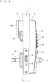
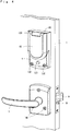
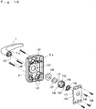
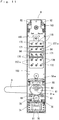
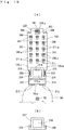
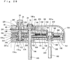
- FIG. 1 An embodiment of the present invention is shown in Figures 1 to 36 .
- Reference numeral 1 denotes a door one side of which is rotatably attached to a frame (not shown) with a hinge. The middle to high position on the other side is provided with a push button lock 2, a mechanical lock.
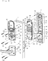
- the push button lock 2 includes the exterior plate 3 having various operation buttons attached on the exterior side of the door 1, a changeover plate 4 mounted on the interior side of the door 1 for setting and altering the security code and setting and releasing the function of the push button lock 2, a handle-mounting plate 5 disposed below the changeover plate 4, and lever handles 6, 7 rotatably protrude from the lower part of the exterior plate 3 and a handle-mounting plate 5, respectively.
- the deadbolt lock 8 is buried in the middle to high position of the door 1, the deadbolt 9 is extendable and retractable from the other side of the door 1 by locking and unlocking operation of the push button lock 2.
- Reference numeral 10 denotes an extendable latch trigger provided immediately below the deadbolt 9 and allows the deadbolt 9 to protrude.
- reference numerals 11, 12, 13, and 14 denote pipe insertion holes formed at the middle to high position of the door 1, into which a connection pipe, as described later, is inserted. The pipe is protruded from the back of the exterior plate 3.
- Reference numerals 15 and 16 denote through holes formed immediately below the pipe hole 11, reference numeral 17 denotes a rod insertion hole formed coaxially with the lever handles 6 and 7.
- the exterior plate 3 includes a housing 18 which protects the internal mechanism and defines the shape.
- the housing 18 is formed in substantially a rectangular-box shape by zinc alloy die-casting, and the front surface is forwardly projecting and gently curved.
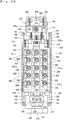
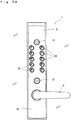
- a reset button 19 having a large diameter, a plurality of push buttons 20 having a slightly smaller diameter than the reset button 19 are disposed on the upper front surface, and an enter button 21 is disposed below them.
- the shaft of the lever handle 6 is rotatably attached immediately below the button 21.
- the push button 20 in the embodiment includes 15 push buttons in total. Ten push buttons indicate numbers on each top surface from one to zero. Five push buttons indicate alphabets on each top surface from A to E. The five push buttons with numbers are arranged in two rows, right and left. The push buttons with alphabets are arranged in a row therebetween. The fifteen push buttons enable the users to set the security code in 2 15 ways, i.e. 32768 ways.
- the push buttons 20 have substantially the same shape. Thus, instead of using two types of characters, only one type of characters can be used for the indication, such as, the alphabet, Japanese Hiragana characters, Japanese Katakana characters, and Roman numbers.
- the upper half on the front surface of the housing 18 is provided with a reset button insertion hole 22 and a plurality of push button insertion holes 23 having an oval shape. Flanges of the push buttons 20 and the cup-like reset button 19 are engaged with the rims of the openings of the holes 22 and 23. A flange 24a of the reset-button shaft 24 is received in the reset button 19.
- the push button 20 is integrally formed with a cup portion and a button shaft 25. The button shaft 25 is projected from the inner surface of the cup portion.
- the reset-button shaft 24 has a substantially semicylindrical shape as shown in Fig. 12 , and protrusions 26 are formed on both sides of the periphery.
- the end surface of the reset-button shaft 24 is formed with a concave groove 27 engageable with the protrusion of a reset pin, as described later.
- a reset-button spring 28 is received in the reset button 19. One end of the spring 28 contacts a button presser plate, as described later, and is compressed. The reset button 19 is projected outwardly against the resilience of the spring.
- the push button 20 is formed in an oval shape and arranged obliquely.
- the pressing surface has a convex surface, and indication such as a letter or a number is marked thereon.
- the button shaft 25 is integrally formed in the push button 20 and the distal end is projected outwardly and arranged so as to engage with the head of a lock pin, which will be described later.
- a push button spring 29 is inserted into the push button shaft 25 and one end of the spring 29 contacts a button presser plate, which will be described later, and is compressed. The push button 20 is projected outwardly against the resilience of the spring.
- the enter button 21 has a substantially cylindrical shape and a flange 21a is formed at the inner end.
- a square-rod-like dog 30 engageable with an enter pin, as described later, is projected from the center of the back end surface of the flange 21a.
- the distal end of the dog 30 is formed with a tapered portion 30a.
- the enter button 21 is inserted in an enter-button insertion hole 31 provided at the lower part of the housing 8, and the flange 21a is engaged with the back end surface 31a.
- a concave hole 32 is formed on both sides of the dog 30, the enter-button spring 33 is received in the concave hole 32.
- One end of the spring 33 contacts the button presser plate, as described later, and is compressed.
- the enter button 21 is projected outwardly against the resilience of the spring.
- a steel button presser plate 35 is secured in the exterior plate 3 via a screw 34.
- the button presser plate 35 is formed in a vertically long rectangular shape and the upper part is provided with an engaging hole 36 having a convex portion 36a engageable with the reset-button shaft 24.
- the lower part of the button presser plate 35 is provided with a rectangular square hole 37 through which the dog 30 is inserted.
- a plurality of through holes 38 into which the button shaft 25 is inserted are aligned horizontally and vertically between the square hole 37 and the engaging hole 36.
- reference numeral 39 denotes a screw hole for the screw 34
- reference numeral 40 denotes a square hole for positioning the button presser plate 35 and is engageable with a projection 41 provided on the bottom inner side of the exterior plate 3.
- Reference numeral 42 denotes a screw hole for a screw 34 and provided on the inside bottom of the exterior plate 3.
- a steel tamper-proof plate 43 is disposed inside the button presser plate 35.
- the tamper-proof plate 43 is formed in a substantially vertically long rectangular shape and slightly narrower than the button presser plate 35.
- the top edge of the plate is provided with a bent piece 44 which is bent outwardly, and the bent piece 44 is engaged with a protrusion 45 provided on the inside bottom of the exterior plate 3.
- the inside bottom of the exterior plate 3, which faces the protrusion 45, is provided with concaved spring bearings 46, 46.
- a spring 47 is interposed between the spring bearing 46 and the bent piece 44, and the tamper-proof plate 43 is biased downwardly against the resilience of the spring 47.
- the upper part of the tamper-proof plate 43 is provided with an engaging hole 48 having a substantially semicircular shape and including a convex 45a engageable with the reset-button shaft 24.
- the lower end of the tamper-proof plate 43 is formed with a rectangular square hole 49 through which the dog 30 extends and retracts, and the square hole 49 is arranged to engage with a tapered portion 30a of the dog 30.
- reference numeral 50 denotes a plurality of elongated holes formed on the tamper-proof plate 43 and into which the button shaft 25 is inserted.
- Reference numeral 51 denotes a square hole for positioning and is engageable with the projection 41.
- a shaft hole 52 is formed at the lower side of the housing 18 and to which a shaft of the lever handle 6 is rotatably attached via a sleeve 53.
- the outer side of the shaft hole 52 is provided with the shaft of the lever handle 6 and the inner side of the shaft hole 52 is provided with a stud 54, a washer 55 and a retaining ring 56 are mounted on the outer surface of the square shaft of the stud 54.
- a bolt 57 is screwed tightly to the shaft of the lever handle 6 from inside of the stud 54, and whereby the lever handle 6 and the stud 54 are connected together and move simultaneously.
- a driving cam 58 is fitted with a square shaft portion of the stud 54 to move simultaneously.
- the driving cam 58 includes a flat cam surface, a rectangular convex portion 58a is formed on the center at one side of the cam surface and is engageable with a notched portion on one side of a bent piece of the lock plate. Then, the upward movement of the lock plate releases the engagement between the convex portion 58a and the notched portion, and thereby allowing the driving cam 58 to rotate against the bias of a torsion spring (not shown).
- the end of the stud 54 is formed with a square hole 59 and a square shaft portion 60a of a joint 60 is fitted therein, and a gear 61 having a substantially fan shape is rotatably mounted to the cylindrical portion formed outside the joint 60.
- a square rod 62 engaged with the deadbolt lock 8 is rotatably inserted to the inner side of the joint 60 and the gear 61.
- Two pins 63, 64 are inserted in the square rod 62.
- the pin 64 is disposed to engage with a pair of fan-shaped grooves (not shown) formed inside the gear 61 and limits the angle of the gear 61.
- the other pin 63 is disposed to engage with a pair of fan-shaped grooves (not shown) formed inside the joint 60.
- reference numeral 62a denotes an engaging stepped portion on the square rod 62.
- Reference numeral 65 denotes a plate cover attached to the lower inner part of the housing 18 and the middle part of which is formed with a through hole 66.
- a boss 61a of the gear 61 is rotatably projected from the through hole 66.
- Reference numeral 67 denotes an engaging ball buried in the shaft of the lever handle 6 and is biased to engage with a sheet 69 via a spring 68, and thereby releasing the overload of the lever handle 6.
- a cylinder lock 70 is mounted downwardly to the lower part of the housing 18, and the cylinder lock 70 includes a cylinder 72 which is rotatable with a key 71 and the shaft end of the cylinder 72 is provided with a square shaft portion 73.
- the square shaft portion 73 is provided to engage with a square hole 75 of a rotation shaft 74, thereby transmitting the rotational force of the square shaft portion 73 to the rotation shaft 74.
- a shaft of the bevel gear 76 is fixed to the inside of the rotation shaft 74 and the bevel gear 76 is rotatably mounted by a bracket 77 integral with the housing 18.
- the bevel gear 76 is disposed to engage with a bevel gear 78 and a support shaft 79 is supported in a blind hole 80 of the housing 18, and the bevel gear 78 is engaged with the gear 61.
- reference numeral 81 denotes a cover attached to the top and bottom of the cylinder lock 70
- reference numerals 82, 83 denote connecting pipes that are projected from the upper and lower edges of the back side of the housing 18 and a female screw is provided inside the pipes.
- the changeover plate 4 is attached to the interior side of the door 1 via the connecting pipe 82 and a connecting pipe 84 projected from a cartridge, as described later.
- the changeover plate 4 is structured with a changeover plate body 85 having a substantially box shape and made of synthetic resin, and a cover 86 made of synthetic resin and from which one part of the outer surface of the body 85 appears.
- a base plate 87 having a rectangular shape is disposed on the back side of the changeover plate body 85, and the upper part of the base plate 87 is integrally provided with a stopper bearing 88.
- Three sheet surfaces 89 are formed at equal angular intervals in circumferential directions of the stopper 88, and projections 90, 90 are formed to face the sheet surfaces 89 located on right and left.
- the center of the stopper bearing 88 is formed with a through hole 91, and an engaging shaft 92 is rotatably inserted in the through hole 15.
- the engaging shaft 92 has a square hole 92a therein and into which a square-shaft-like memory change pin is engageably inserted. The pin will be described later.
- One end of the engaging shaft 92 is formed with a square shaft portion 93 and the portion 93 fits within a square hole 95 of a stopper 94.
- a lip portion 96 is formed on a stopper 94 and seated on the sheet surface 89, and the engaging shaft 92 is positioned at a predetermined position. The lip portion contacts the protrusion 90, and thereby limiting the rotational angle of the engaging shaft 92.
- the projected portion 85a is formed on the surface of the changeover plate body 85, a large-diameter through hole 97 and a blind hole 98 are formed on the center of the projected portion 85a, and the through hole 97 is located at the upper part and the blind hole 98 is located at the lower part.
- the blind hole 98 has a through hole 99 at the center thereof.
- a cylinder lock 100 is inserted into the through hole 97 as a rotator, a nut 101 is threaded into the threaded portion of the cylinder lock 100, and thereby securing the cylinder lock 100 to the projected portion 85a.
- a cylinder 103 turnable by inserting a key is provided inside the cylinder lock 100.
- the cylinder 103 has a square shaft portion 104 at the end thereof, the square shaft portion 104 is engaged with a square hole 105 formed at the square shaft portion 93, and enabling the rotational force of the cylinder 103 to be transmitted to the engaging shaft 92.
- a spring 106 is interposed between the stopper 94 and the cylinder lock 100, the engaging shaft 92 is biased to the door side against the resilience of the spring 106, and thereby maintaining engagement with a memory change shaft, as described later.
- the reset button 19 is pressed and then a desired security code is entered with the push buttons 20, and the key 102 is inserted into the cylinder lock 100 and turned 90 degrees from a neutral position to a set direction.
- the reset button 19 is pressed, and then the key 102 is inserted into the cylinder lock 100 and turned 90 degrees from the neutral position to a reset direction. More specifically, the cylinder lock 100 normally resides at the neutral position. The lock 100 is turned from the neutral position to the set direction when the security code is set. The lock is turned from the neutral position to the reset direction when the security code is released or altered. After the lock is turned, the key 102 can be taken out when returned to the neutral position.
- the cylinder lock 100 is used as a means of providing a rotational force to the engaging shaft 92 and allows a key-holder to change or set the security code.
- a thumbturn, a tool, a coin may be engaged with the engaging shaft 92 as a rotator to rotate the engaging shaft 92.
- a changeover shaft 108 integral with the latch changeover knob 107 is inserted into the through hole 99 and rotatably inserted into the through hole 16 via a through hole 109 formed on the base plate 87.
- a square hole 110 is formed in the changeover shaft 108 and a reset pin having a square shaft, which will be described later, is engageably inserted therein.
- the base of the changeover shaft 108 is formed with a square shaft 108a, the square shaft 108a is fitted within a square hole 112 of a stopper 111.
- a lip portion 113 of the stopper is provided to engage with a convex portion (not shown) formed on a back side of the blind hole 98 and limits a rotational angle of the changeover shaft 108.
- the latch changeover knob 107 is used to release the lock, which is locked and unlocked by entering the security code with the push button 20, and makes a door open by door handles 6, 7. More specifically, the security code is entered after pressing the reset button 19, the enter button 21 is then pressed, and the door is unlocked by turning the door handle 7. The cover 86 is opened with the state maintained, and the latch changeover knob 107 is turned to the latch side, that is, the direction of free.
- reference numeral 114 denotes a retaining ring attached to the periphery of the changeover shaft 108.
- Reference numeral 115 denotes a washer, and further, reference numeral 116 denotes a spring inserted between the washer 115 and the stopper 111.
- the changeover shaft 108 is biased to the side of the door 1 against the resilience of the spring.
- a screw holes 118, 118 into which a screw 117 is inserted are formed on the upper part of the projected portion 85a, a projection 119 is formed between the screw holes 118, and a hinge case 120 having a substantially U-shape cross-section is fitted to the projection 119.
- the hinge case 120 is disposed in a cutout section 121 formed at pivot portions of the upper end of the cover 86, and a pair of pivots 122, 122 having a substantially V-shape apex are formed on the end faces that face the cutout section 121.
- a substantially V-shaped engaging groove formed on the end surface of a hinge cam 123 is fitted with the apex of the pivot 122.
- a spring 124 is inserted between hinge cams 123, 123, and thereby maintaining a snug fit between the apex and the engaging groove.
- the hinge cam 123 has a square shaft engageable with the inner surface of the hinge case 120, the cover 86 is attached so as to rotate up and down about the pivots 122 via the hinge cams 123, 123, and the opened or closed state is maintainable.
- a step portion 125 having a substantially key-hole configuration is protruded from the lower part of the base plate 87 and is defined by a rib 125a, a through hole 126 is formed on the lower part of the body 85, and a deadlock button 127 is inserted from the inside of the body 85.
- a flange 127a is formed at the end surface of the deadlock button 127, and the lower part of a switching plate 128 is arranged to contact the flange 127a.
- the switching plate 128 is made of a steel plate and has an elongated rectangular shape, one end has a bent leg 129, and the other end is engageable with the inside of the lip portion 113.
- a spring bearing 130 is formed on the middle of the switching plate 128 by bending a pair of plates.
- a spring 131 is disposed between the step portion 125 and the switching plate 128, and the switching plate 128 is biased to the side of the deadlock button 127 against the resilience of the spring 131.
- the deadlock button 127 is normally biased outwardly of the door 1 and the leg 129 is seated on the step portion 125 when pressed.
- the displacement of the other end is increased by leverage of the switching plate 128, the stopper 111 is moved together via the lip portion 113, and rotation of the stopper 111 enables the latch changeover knob 107 to rotate to the side of the deadlock position.
- reference numeral 132 denotes a screw hole formed on the lower part of the changeover plate body 85 and a screw 133 is insertable therein.
- the handle-mounting plate 5 is formed substantially in a shape of a box by zinc alloy die-casting and a through hole 134 is formed on the concave center surface, which is inside the plate 5.
- a square shaft portion 7a which is a shaft end of the lever handle 7, fits within the hole 134.
- a plurality of engaging teeth 135 are formed on the inner surface of a shaft hole, and thereby enabling a square portion of the square rod 62 to engage with the teeth 135.
- a washer 136 and a retaining ring 137 are mounted to the square shaft portion 7a inserted in the through hole 134, and thereby holding the square shaft portion 7a in place.
- a back plate 139 is attached to a step portion 5a formed inside the handle-mounting plate 5 with screws 138.
- the through hole 140 is formed on the center of the back plate 139.
- a boss 142 of a spring bearing 141 is inserted in the through hole 140.
- a plurality of engaging teeth 143 are formed on the inner surface of a shaft hole of the boss 142, and thereby enabling a square portion of the square rod 62 to engage with the teeth 143.
- a stopper (not shown) is projected from the outer periphery of the spring peg 145 and provided to engage with the spring pegs 144, 145, and thereby limiting the rotational angle of the spring bearing 141 and the lever handles 6, 7. Both ends of the torsion spring 146 are engaged with the spring pegs 144, 145, the square rod 62 and the lever handles 6, 7 are rotatable to the original position against the resilience of the torsion spring 146.
- reference numeral 147 denotes a screw hole formed on the handle-mounting plate 5.
- the handle-mounting plate 5 is attached to the door 1 by tightening screws 148 to the connecting pipes 83, 175.
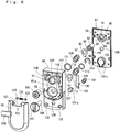
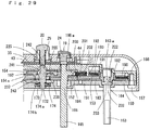
- the security-code controller 149 which has a rigid cartridge-like structure, is disposed between the exterior plate 3 and the door 1.
- the controller 149 is detachably attached to the exterior plate 3 and can be replaced.
- the security code entered with the push button 20 can be set and stored in the security-code controller 149, and is releasable and alterable.
- the controller 149 is formed in an elongated rectangular block shape, which is smaller than the exterior plate 3, and is structured by laminating a plurality of plate-like components.
- the security-code controller 149 is structured by laminating the following components; a controller cover 150 disposed on the side of the door 1, a memory set plate 151 disposed on the outer side of the cover 150 and on the side of the exterior plate 3, a memory change intermediate plate 152 disposed on the outer side of the plate 151, a memory reset plate 153 disposed on the outer side the of plate 152, a reset plate 154 disposed on the outer side the plate 153, a lock plate 155 disposed on the outer side the reset plate 154, and a controller case 156 disposed on the outer side of the plate 155 and adjacent the tamper-proof plate 43.
- the security-code controller 149 is made by assembling components 150 to 156. More specifically, a screw 157 is inserted in a screw hole 158 of the controller cover 150, and is screwed in a screw hole 159 on the controller cover 156. Then, a screw 160 inserted in a screw hole 161 on the controller case 156 is screwed into a screw hole 162 formed inside the exterior plate 3, and whereby security-code controller 149 is detachably attached inside the exterior plate 3.
- the controller cover 150 is formed in a substantially elongated rectangular plate by zinc alloy die-casting.
- a stepped hole 164 is provided at the upper part and a memory change pin 163 is insertable therein.
- a stepped hole 166 is formed at the lower part and a reset pin 165 for changing the position to the latch position is insertable therein.
- a plurality of stepped washer holes 167 are provided at the middle part, and a through hole 169 having a step is provided at the lower end and an enter pin 168 is insertable therein.
- a small-diameter through hole 172 is formed on the bottom of the washer hole 167, a pair of protrusions 173 is formed on the inner side of the opening of the through hole 172, and a disk-like stop washer 174 is rotatably received in the washer hole 167.
- reference numeral 170 denotes an indication of the security code on the outer periphery of the opening and corresponds to an indication of the push button 20.
- Reference numeral 171 denotes a reinforcing bead.
- the stop washer 174 is formed with a square hole 174a at the center and engageable with a square shaft of a lock pin, which will be described later.
- the back side is formed with an engaging groove 174b having a cross shape and engageable with the protrusions 173, and thereby maintaining the rotational position of the lock pin at 90 degrees.
- reference numerals 175 denote connecting pipes protruded from the middle part of the plate cover 170 and from the lower end part of the controller cover 150, and female screw potions are formed on the inner surfaces.
- Protrusions 176, 177 for positioning are provided on the upper part and the lower ends of the inner surface of the controller cover 150 and are engageable with the inner wall of the controller case 156.
- a rectangular step portion 178 having a through hole 169 is protruded from the center of the protrusion 177, concave grooves 179, 180 are formed on the outside the step portion 178, to which a reset pin assembly to be described later, is attached.
- reference numerals 221 denote pin holes for positioning formed on the upper and lower ends of the controller cover 150.
- the memory set plate 151 is formed in an elongated rectangular shape by press molding a stainless steel plate and disposed on the inner side of the controller cover 150 and slidable up and down. Cutout portions 181 engageable with the protrusions 176 are formed on the upper part to limit the sliding displacement to the length of the cutout portions 181.
- a bent piece 182 is formed on the upper end of the memory set plate 151, springs 190 are interposed between the outer surface of the bent piece 182 and the upper inner surface of the controller case 156, and the memory set plate 151 is biased to move downwardly against the resilience of the springs 190.
- a memory change cam which will be described later, is rotatably disposed on the inner side of the bent piece 182 and is engaged with the bent piece 182, and whereby the memory set plate 151 moves up and down.
- Openings 183, 184 are formed on the upper part of the memory set plate 151 and the memory change pin 163 and the reset pin 165 are insertable therein, respectively.
- Rectangular sliding grooves 185 are aligned in three rows from left to right, and a plurality of dogs 186 having a substantially L-shape are provided on one sides of the sliding grooves 185 and are engageable with one ends of the engagement pawls of the lock pins, which will be described later.
- the memory change intermediate plate 152 is formed by press molding a corrosion-resistant steel plate and shaped as an elongated rectangular frame, and is secured to adjacent the inner side of the memory set plate 151. Cutout portions 187 engageable tightly with the protrusions 176 are formed on the upper part of the memory change intermediate plate 152, and an opening 188 into which the reset pin 165 is inserted is formed therebetween.
- the sliding grooves 185 and the dogs 186 appear from an opening 189 formed by cutting the lower part of the plate 152 in a rectangular shape.
- the memory reset plate 153 is formed in an elongated rectangular shape by press molding a stainless steel plate and disposed on the inner side of the memory change intermediate plate 152 and is slidable up and down. The upper and lower part of the plate 153 are engaged with the protrusions 176, 177, respectively, and thereby limiting the sliding displacement.
- a bent piece 191 is formed on the upper end of the memory reset plate 153 and disposed to engage with a protrusion 192 on the inner side of the controller case 156.
- Springs 193 are interposed between the protrusion 192 and the bent piece 191, and the memory reset plate 153 is biased to move upwardly against the resilience of the spring 193.
- Opening 194 is formed on the upper part of the memory reset plate 153 and the reset pin 165 is insertable therein.
- Rectangular sliding grooves 195 are arranged on the lower part in three rows from left to right, and a plurality of dogs 196 having a substantially inverted L-shape and a symmetrical configuration with the dog 186 are provided to engage with one sides of the sliding grooves 195 and the dogs 196 are provided to engage with the other ends of the lock pins, as described later.
- the reset plate 154 is formed in an elongated rectangular shape by zinc alloy die-casting.
- a reset-spring presser plate 197 having an elongated rectangular shape and made of a corrosion-resistant steel plate, is secured to one side of the memory reset plate 153 by caulking via a pin 154a.
- the reset plate 154 is provided on the inner side of the memory reset plate 153 and slidable up and down.
- the upper end of the reset plate 154 is engageable with the end of an opening of a concave portion, as described later, and a square portion 154a on the lower part is provided to engage with a step portion 198 on the inner side of the controller case 156, and thereby limiting the up and down movement.
- a rectangular opening 199 into which the reset pin 165 is inserted is formed on the upper part of the reset plate 154, and a tapered surface 199a is formed on the top inner surface and engageable with a tapered portion of the reset pin 165, as descried later.
- a protrusion 200 is formed on the top end of the reset plate 154 and engageably inserted in the protrusion 201 provided on the inner side of the controller case 156.
- a spring 202 is interposed between the inner surface of the protrusion 201 and the protrusion 200. The reset plate 154 is biased to move downwardly against the resilience of the spring 202.
- the reset plate 154 and the a reset-spring presser plate 197 are formed with the same number of oval elongated holes 203 as the push buttons 20, and spring-receiving grooves 204 are provided to face the elongated holes 203.
- Each end of the spring-receiving groove 204 is provided with a pin 206 that supports a reset spring 205, which is a torsion spring.
- One end of the reset spring 205 is engaged with one surface of the spring-receiving groove 204 and the other end, which is a free end, is provided on the other side of the spring-receiving groove 204 and engageable with a lock pin, as described later.
- reference numeral 250 denotes an opening window formed on the lower end of the reset plate 154 and an enter-pin assembly, as described later, can be attached.
- the lock plate 155 is formed in an elongated rectangular shape by press molding a stainless steel plate and is disposed on the inner surface of the controller case 156 and is slidable up and down The upper end is engaged with the lower end surface of a concave portion 201, the square portion 155a on the lower part is engaged with the step portion 198, and thereby limiting the up and down movement of the lock plate 155.
- a rectangular opening 207 is formed on the upper part of the lock plate 155 and the reset pin 165 is rotatably and engageably inserted therein, and a cutout groove 207a is formed at the center of the upper rim.
- the up and down position of the lock plate 155 is regulated by rotational angle of the reset pin 165 linked to the set position of the changeover knob 107 of the changeover plate 4 so that the lock can be used in an auto lock state, latch state, and deadlock state.
- the changeover knob 107 is set to the auto lock position, a protrusion of the lock pin 165 to be described later is positioned laterally in the opening 207 as shown in Fig. 25(a) .
- a large space is formed between the end surface of the engaging piece and the lower edge of the opening 207 as described later, and enabling the lock plate 155 to displace up and down and to respond to rotation of the driving cam 58 when the lock is unlocked.
- the door In the latch mode, the door is not locked when closed and can be opened from inside and outside by the lever handles 6, 7 without pressing the push button 20.
- the changeover knob 107 is set to the latch (free) position, rotation of the reset pin 165 allows the protrusion to engage with the cutout groove 207a of the opening 207 as shown in Fig. 25(b) .
- the lock plate 155 can be displaced upwardly a given amount and respond to the rotation of the driving cam 58.
- the door is automatically locked when closed and opened by key operation of the cylinder lock 70 from the exterior side.
- the changeover knob 107 is set to the deadlock position, rotation of the reset pin 165 allows the protrusion to engage with the lower opening edge of the opening 207 and prevents upward displacement of the lock plate 155.
- Bent pieces 208 are formed on the both sides of the lock plate 155 and provided to engage with elongated grooves 209 on the inner side of the controller case 156.
- Springs 210 are interposed between the elongated grooves 209 and the bent pieces 208 so that the lock plate 155 is biased to move downwardly against the resilience of the springs 210.
- the same number of plate key holes 211 as the push button 20 are formed on the middle of the lock plate 155 and have a substantially hook shape.
- the first and second shaft keys 240, 241 of the lock pin, as described later, are rotatable in the plate key holes.
- Plate lock holes 211a having a rectangular shape are formed on the plate key holes 211 and they are in communication with each other.
- the plate lock hole 211a is narrower than the plate key hole 211.
- the lock plate 155 is moved upwardly when abutment surfaces 240a, 241a of the first and second shaft keys are in parallel to the plate lock holes 211a.
- the lock plate 155 is prevented from moving upwardly when the abutment surfaces 240a, 241a of the first and second shaft keys intersect each other, i.e., orthogonal positions.
- the abutment surface 241a of the second-shaft key 241 is parallel to the plate lock hole 211a, and whereby the lock plate 155 is movable.
- the abutment surface 241a of the second shaft key 241 of the lock pin, in which the security code is set is positioned to abut an opening rim of the plate lock hole 211a, and thereby preventing movement of the lock plate 155.
- Bent pieces 212, 213 are respectively projected inwardly and outwardly from the bottom of the lock plate 155, and are engageable with the driving cam 58.
- the bent piece 212 is wider than the bent piece 213 and slidably contacts the cam surface of the driving cam 58, and wear and abrasion of the cam surface may be prevented.
- the bent piece 213 is thicker and narrower than the bent piece 212 and is provided on the middle with the cutout portion 213a and is engageable with the convex portion 58a of the driving cam 58.
- a substantially rectangular opening 214 is formed on the lower part of the lock plate 155 and the enter-pin assembly is provided therein.
- Bent pieces 215 having an L-shape are protruded toward the exterior plate 3 from both sides of the opening window 214.
- An engagement pawl 216 is raised toward the exterior plate 3 on the upper edge of the opening window 214 and the end portion is engageable and movable with a recess on the controller case 156, as described later.
- a cushion plate 217 is disposed adjacent the engagement pawl 216.
- Bent pieces 219 having a substantially L-shape are protruded from both sides of the lower part of the cushion plate 217.
- the bent pieces 215, 219 are engageable and movable with an elongated groove on the controller case 156, as described later.
- Brake springs 220 are interposed between the bent pieces 215, 219 and biasing the cushion plate 217 downwardly.
- the lock plate 155 is moved upwardly via the slider by movement of an enter pin, as described later. Then, the cushion plate 217 is moved upwardly via the second slider against bias of the brake spring 220. Thus, the shaft force of enter pin is lowered, improper engagement force of the lock plate 155 to the lock pin is lowered, and whereby damage of the lock pin is prevented.
- the controller case 156 is formed in a vertically elongated rectangular box by zinc alloy die-casting, and a cam hole 222 is formed on the inner top surface and the shaft of a memory change cam, as described later, is insertable therein, and a stopper 223 is projected from the adjacent position.
- a through hole 224 is formed immediately below the protrusion 201 and the reset pin 165 is insertable therein.
- a plurality of stepped holes 225 for rotatably receiving the head of the lock pin and a first-shaft key 240, as described later, are formed below the through hole 224.
- a rectangular engaging groove 226 engageable with the engagement pawl 216 is formed at the lower end and a pin hole 227 into which an enter pin 168 is inserted is formed immediately below the groove 226.
- reference numerals 228 denote long grooves in which the bent pieces 215, 219 are insertable.
- Reference numerals 229 denote pins protruded from the upper and lower edges on the inner side of the controller case 156 and are inserted in the pin holes 221.
- the shaft 231 of the memory change cam 230 resides in the cam hole 222, and the shaft is provided at the end with a square hole 232.
- a square shaft portion 163a, one end of the memory change pin 163, resides in the square hole 232 and the flange 233 is engaged with the opening edge of the square hole 232.
- the memory change pin 163 is formed like a shaft by zinc alloy die-casting.
- the other end of the square shaft portion 163a is formed in a square shaft and shifted 90 degrees in phase with respect to the square shaft portion 163a.
- the other end of the memory change pin 163 projected from the controller cover 150 toward the outer surface of the door 1, and is engaged with a square hole 92a of the engaging shaft 92 and linked to the cylinder 103 provided on the changeover plate 4.
- the memory change pin 163 is rotatable with a key in the direction of set or reset, and operable when setting, releasing, and altering the security code.
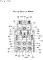
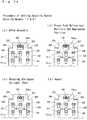
- the reset button 19 when setting the security code, depress the reset button 19 first to move up the reset plate 154 and release engagement of the reset spring to a lock pin to be described later.
- the lock pin is returned to the original position by a set spring, and the push button 20 before setting the code is returned to the original position, clearing an erroneous push.
- One side surface of the memory change cam 230 is normally engaged with the inner side of the bent piece 182 of the memory set plate 151, the other side is engaged with the bent piece 191 of the memory reset plate 153, and are ready for setting, releasing, and altering the security code.
- the desired security code is entered with the push button 20. Then, the cylinder lock 100 is rotated in the set direction, a counterclockwise direction in Fig. 8 , by inserting a key 102.
- the memory change cam 230 is rotated in the same direction and the memory set plate 151 is moved up via the bent piece 182.
- the dog 186 is engaged with the engagement pawl of the lock pin and then rotated. Then, the lock is reset while maintaining the rotational position via a set spring, and the lock pin is returned to the original position.
- the security code is released and altered in the following manner.
- the key 102 is turned to the reset direction, that is a clockwise direction in Fig. 18 , and rotate the memory change cam 230 in the same direction.
- the memory reset plate 153 is moved down via the bent piece 191, the dog 196 is engaged with the engagement pawl of the lock pin and rotated in a counterclockwise direction, and thereby returning the memory reset plate 153 to the original position by resilience of the spring 190.
- the reset pin 165 is formed like a square shaft by zinc alloy die-casting and has substantially the same diameter as the memory change pin 163 and is longer than the pin 163 as shown in Fig. 23 , and is formed at one end thereof with a square-shaft like protrusion 234 engageable with the concave groove 27 of the reset-button shaft 24.
- a lateral protrusion 235 is provided on the middle of the reset pin 165, an offset position.
- An engagement piece 236 having a semicircular shape is formed adjacent the protrusion 235 and formed at one side with an engagement surface 236a.
- the engagement surface 236a has substantially a cone shape and is engageable with the tapered surface 199a of the reset plate 154.
- the reset plate 154 is moved up by the engagement surface 236a in accordance with depression displacement of the reset button 19 and engagement of the reset spring to the lock pin is released, and the lock pin is returned to the original position.
- the other end of the reset pin 165 is formed like a square shaft, the same phase as the protrusion 234, and the square shaft portion is engageably inserted in the square hole 110 of the changeover knob 107.
- the lock pin 237 is formed like a shaft by zinc alloy die-casting and provided at one end, the door side, with a square shaft portion 237a engageable with the square hole 174a of the stop washer 174.
- An engagement pawl 238 substantially in the form of a triangular prism is protruded radially from the middle part and is engageable with the dogs 186, 196.
- the engagement pawl 238 is provided at a 45 degree position from the shaft center of major axes of the first and second shaft keys disposed orthogonal to each other, as described later.
- the engagement pawl 238 is rotatable 90 degrees forwardly and reversely when engaged with the dogs 186, 196.
- a cone flange 239 having an inverted-circular truncated cone is provided in proximity to the engagement pawl 238.
- the first and second shaft keys 240, 241 having the same shape are stacked on the flange 239.
- the shaft keys 240, 241 have a cross section of an elongated square shaft, formed by cutting the both sides of the shaft periphery to be parallel to each other, and arranged orthogonal to each other, shifting the center of the major axis side in phase by 90 degrees.
- the first shaft key 240 on the top side is orthogonal to the cross section of the square shaft portion 237a.
- the second shaft key 241 is arranged immediately above the larger diameter side of the cone flange 239 and has the same phase as the cross section of the square shaft portion 237a, and a shaft head 242 is projected from the first shaft key 240.
- the shaft head 242 is rotatably inserted in the stepped hole 225 together with the first shaft key 240, the end surface faces the opening of the stepped hole 225 and is engageable with the end of the button shaft 25.
- the second shaft key 241 is positioned within the plate key hole 211, the abutment surface 241a, which is a flat surface, is provided parallel to the plate lock hole 211a, and whereby the lock plate 155 is movable.
- the square shaft portion 237a, one end of the lock pin 237, is inserted in the square hole 174a of the stop washer 174 and the other end faces the opening of the stepped hole 225.
- a lock spring 243 having a conical coil-like configuration is interposed between a step of the square shaft portion 237a and the stop washer 174, and the lock pin 237 is biased toward the push button 20 against the resilience of the spring 243.
- the shaft head 242 and the first shaft key 240 of the lock pin 237 are positioned within the stepped hole 225.
- the abutment surface 241a of the second shaft key 241 is provided parallel to the plate lock hole 211a of the lock plate 155, and whereby the lock plate 155 is movable. This state is shown in Fig. 34(a) .
- the engagement pawl 238 of the lock pin 237 is positioned over the memory set plate 151 and the memory reset plate 153.
- the engagement pawl 238 is arranged obliquely at an angle of 45 degree with respect to the square shaft portion 237a and is engageable with the dog 186 of the memory set plate 151 and the dog 196 of the memory reset plate 153.
- the position is kept by engagement between the engaging groove 174b of the stop washer 174 and the protrusion 173 of the controller cover 150.
- the free end of the reset spring 205 is positioned close to the smaller diameter side of the cone flange 239.
- the reset spring 205 is positioned on the larger diameter side of the cone flange 239 and keeps the lock pin 237 in the depressed position.
- the reset button 19 is depressed, the reset pin 165 is moved together and the reset plate 153 is moved upwardly.
- the free end of the reset spring 205 is retracted and whereby the engagement is released, and the lock pin 237 is moved upwardly via the lock spring 243 and is returned to the original position.
- the engagement pawl 238 is engaged with the dogs 186, 196 of the memory set plate 151 and memory reset plate 153 and then rotated.
- the square shaft portion 237a is moved simultaneously and the stop washer 174 is rotated.
- the engaging groove 174b on the back side of the washer 174 is engaged with the protrusion 173, and thereby maintaining the rotational angle of the lock pin 237.
- the enter pin 168 and an assembly of the enter pin 168 are attached to the corresponding position on the controller case 156, which faces the dog 30.
- the enter pin 168 is formed like a shaft by zinc alloy die-casting and one end of which is inserted in the pin hole 227 provided at the lower part of the controller case 156 and the end surface is engageable with the enter pin 168.
- a rectangular flange 244 is formed at the middle part of the enter pin 168 and has a tapered surface 244a on the upper part of the flange 244, and a shaft having a step is protruded at the other side of the flange 244.
- the first slider 245 having a rectangular frame shape is provided outside the flange 244 and a tapered surface 245a engageable with the tapered surface 244a is formed on the upper inner surface.
- the second slider 246 having a rectangular frame shape is provided to engage with the outer periphery of the first slider 245, and the top and bottom end surfaces of the slider 246 are provided to engage with the inner surface of the opening 218.
- the cushion plate 217 is engaged with the upper end surface of the second slider 246, the third slider 247 having a rectangular frame shape is provided outside the second slider 246 and the upper end is engageable is a projection 246a of the second slider 246.
- Legs 248 are projected from one side of the third slider 247 and disposed to engage with the outer periphery of the second slider 246, and the outer surface is provided to engage with the left and right inner surfaces of the opening 218.
- the enter button 21 When the enter button 21 is pressed, the enter pin 168 is depressed. Then, the first slider 245 is moved up via the tapered surfaces 244a, 245a, moving the second and the third slider 246, 247 simultaneously. The top end of the first slider 245 is engaged with the tapered surface 216, pushing up the tapered surface 216 and moving the lock plate 155 simultaneously. Then, the bent pieces 212, 213 are retracted from a rotational area of the driving cam 58 and enable the driving cam 58 to rotate, and whereby the lock is unlocked.
- the lock plate 155 Upon unlocking the lock, in the case where the correct security code is not entered with the push button 20, the lock plate 155 is not movable engaging with the shaft key 242 of the lock pin 237, and the lock cannot be unlocked. Under these circumstances, when the enter button 21 is pressed, the first to third sliders 245 to 247 are moved upwardly by depression displacement of the enter pin 168, the brake spring 220 is compressed and moves the cushion plate 217 upwardly, and whereby shaft force of the enter pin 168 is absorbed. Therefore, the lock plate 155 is prevented from being damaged, and upward displacement of the lock plate 155 is controlled. The load on the lock pin 237 which prevents the upward movement is reduced. The lock pin 237 requires less mechanical strength and the material can be replaced from steel to zinc alloy die-casting, which is inexpensive. Further, tampering or trouble caused by erroneously pushing the push buttons 20 can be prevented.
- the push button lock thus configured includes the exterior plate 3 on the exterior surface of the door 1, the changeover plate 4 and the handle-mounting plate 5 provided on the interior surface of the door 1, and they are separately manufactured and attached to the inner and outer positions of the door 1, respectively.
- the changeover plate 4 and the handle-mounting plate 5 are separately manufactured and provided on the interior surface of the door 1 so that the handle-mounting plate 5 becomes small and light compared to the conventional one. Further, the changeover plate 4 and the lever handle 7 can be operated independently and smoothly.
- the exterior plate 3 is manufactured in the following manner.
- the exterior plate 3 is composed of a housing assembly and the security-code controller 149.
- the housing assembly includes a housing 18 to which the reset button 19, the enter button 21, and the lever handle 6 are assembled.
- the security-code controller 149 is attached to the inner side of the assembly. After they are separately manufactured, they are integrally attached to each other.
- the housing assembly and the security-code controller 149 can be produced in an efficient manner. Since the security-code controller 149 has a common structure, various surface designs are available, corresponding to the shapes of the housing 18, the push button 20, the reset button 19, the enter button 21, and the number and arrangement of the push button 20. In other words, since the security-code controller 149 can be used for the various surface designs of the housing 18, the design is simplified and thus provides easier maintenance of the security-code controller 149.
- the housing assembly is manufactured in the following manner.
- the reset-button shaft 24 and the reset-button spring 28 are inserted in the reset-button insertion hole 22 from the inside of the housing 18.
- the push button 20 integral with the button shaft 25 and the push button spring 28 are inserted within each of the push button insertion hole 23 from the inside of the housing 18.
- the enter button 21 is inserted in the enter-button insertion hole 21, and the enter button spring 33 is inserted in the concave hole 32 on the inner side of the button 21.
- the push button 20 is formed integral with the button shaft 25, the number of components can be reduced, and thereby making assembly of the push button 20 easier.
- the button presser plate 35 is received inside these components.
- the screw 34 is inserted in the screw hole 39 on the plate 35 and screwed into the screw hole 42 on the housing 18 to fix the plate 35 in place. This state is shown in Fig. 12 .
- the tamper-proof plate 43 is disposed on the button presser plate 35, the bent piece 44 is engaged with the protrusion 45, the spring 47 is inserted between the bent piece 44 and a convex wall immediately above the bent piece 44, and whereby the tamper-proof plate 43 is biased downwardly.
- the sleeve 53 is inserted in the outer side of the shaft hole 52.
- the shaft of the lever handle 6 is fitted within the outer side of the sleeve 53.
- One end of the stud 54 is joined to the inner end of the shaft via the sheet 69 and the bolt 57 is screwed into the shaft of the lever handle 6 and clamped from the inner side of the stud 54.
- the driving cam 58 is fitted with the periphery of the square shaft of the stud 54, the square shaft of the joint 60 is fitted within the square hole 59 formed at the end of the cam 58, and the gear 61 is rotatably attached to a boss formed at the end thereof.
- the square rod 62 is inserted in the inner side of the joint 60, two pins 63, 64 are inserted in the square rod 62 and one of the pins 64 is engaged with an angle regulation groove (not shown) and the other pin 63 is engaged with the end of the stud 54.
- the rotational angle of the gear 61 is regulated at 90 degrees.
- the support shaft 79 of the bevel gear 78 is rotatably inserted in the blind hole 80 at the lower part of the housing 18.
- the bevel gear 78 is provided to engage with the gear 61.
- the shaft of the bevel gear 76 engaged with the bevel gear 78 is rotatably supported in the bracket 77, and the shaft is connected to the rotation shaft 74.
- the cylinder lock 70 is attached to the bottom of the housing 18 via a mounting cover 81.
- the square shaft portion 73 integral with the cylinder 72 of the cylinder lock 70 is engaged with the square hole 75 of the rotational shaft 74, and rotational displacement of the cylinder lock 70 is engageable with the gear 61.
- a plate cover 65 from which the connecting pipes 83 are projected is attached to the lower inside of the housing 18.
- the boss 61a of the gear 61 and the square rod 62 are projected from the cover 65.
- the support shaft of the bevel gear 78 which is the same shaft as the support shaft 79, is rotatably projected therefrom.
- the connecting pipes 82 are attached to the housing 18 in advance or after a series of assembly.
- the components, the controller case 156 and the controller cover 150 are formed by zinc alloy die-casting.
- the memory set plate 151, the memory change intermediate plate 152, the memory reset plate 153, and the reset plate 154 are formed by press molding of a steel plate.
- the memory change pin 163, the memory change cam 230, the reset pin 165, and the lock pin 237 are formed by zinc alloy die-casting.
- the enter pin 168 and the first to third sliders 215 to 247 are formed by zinc alloy die-casting.
- an assembling jig (not shown) is prepared for engaging the controller case 156.
- the controller case 156 is received in the jig with the top upward.
- the enter pin 168 is inserted in the pin hole 227 on the lower part of the case 156.
- the lock plate 155 to which the cushion plate 217 is assembled is received inside the controller case 156.
- the bent pieces 208 are engaged with the opening edges of the elongated grooves 209.
- Springs 210 are inserted between the bent pieces 208 and the inner surfaces of the elongated grooves 209 respectively, and the lock plate 155 is biased downwardly.
- the engagement pawl 216 integral with the lock plate 155 is movably received in the engaging groove 226 of the controller case 156, and the end portion is provided to face the end portion of the flange 244 of the enter pin 168.
- the first to the third sliders 245 to 247 are provided to engage with the flange 244 in sequence and the cushion plate 217 is engaged with the top end of the second slider 246.
- the shaft head 242 of the lock pin 237 is inserted from the plate key hole 211 to the stepped hole 225 of the controller case 156.
- the first shaft key 240 which is the top end, intersects at the center of the plate key hole 211.
- the second shaft key 241 is arranged parallel to the plate key hole 211. Accordingly, the engagement pawl 238 is arranged in close proximity to the reset plate 154 and provided obliquely downward from the center of the plate key hole 211. This state is shown in Figures 27 and 28 .
- the reset plate 154 into which the reset spring 205 is attached is placed on the lock plate 155.
- a shaft 200 is inserted in the concave portion 201 of the controller case 156 and the spring 202 is interposed therebetween to bias the reset plate 154 downwardly.
- the engagement pawl 238 is arranged on the periphery of the elongated hole 203.
- the protrusion 234, the head of the reset pin 165, is inserted in the opening 207 of the lock plate 155, and then inserted into the through hole 224 of the controller case 156 to appear from the outer surface of the case 156.
- the tapered surface 236a of the reset pin 165 is provided to engage with the tapered surface of the reset plate 154.
- the legs 248 of the third slider 247 are inserted in the open window 250 of the reset plate 154, and the third slider 247 is disposed on the second slider 246.
- the memory reset plate 153 is disposed on the reset plate 154 and the reset pin 165 is inserted into the opening 194.
- the bent piece 191 is provided to engage with the upper wall of the protrusion 201.
- the spring 193 is inserted between the upper wall and the bent piece 191.
- the reset plate 153 is biased to move upwardly.
- the memory change intermediate plate 152 is received on the memory reset plate 153 and the reset pin 165 is inserted into the opening 183.
- the shaft 231 of the memory change cam 230 is inserted in the cam hole 222 of the controller case 156.
- the memory change pin 163 is inserted in the square hole 232 and positioned at a neutral position, which means directing the memory change cam 230 to the right, as shown in Fig. 32 .
- the memory set plate 151 is disposed on the memory change intermediate plate 152, and the memory change pin 163 is inserted into the opening 183.
- the reset pin 165 is inserted into the opening 184, and the bent piece 182 at the upper end is engaged with the upper surface of the memory change cam 230.
- the springs 190 interposed between the bent piece 182 and the concaved grooves on the upper end of the controller case 156.
- the memory set plate 151 is biased to move downwardly. Further, the memory change cam 230 is biased and positioned at the neutral position. This state is shown in Fig. 32 .
- the controller cover 150 is put on the memory set plate 151.
- the memory change pin 163 is inserted into the stepped hole 164, and the protrusion 177 is provided to engage with the cutout portions 181 of the memory set plate 151.
- the enter pin 168 is inserted in the through hole 169 of the controller cover 150, and the concave grooves 179, 180 are put on the reset pin assembly.
- the assembly can be judged to be appropriate when the cut portions on both surfaces are located on the right and left with respect to all the square shaft portions 237a of the lock pins 237 as shown in Fig. 32 . Then, the smaller diameter side of the lock spring 243 is inserted in the square shaft portion 237a.
- lubrication grease (not shown) is applied to the surface of the protrusion 173 in the washer hole 167 of the controller cover 150.
- the stop washer 174 is received on the grease and pressed to fit the square hole 174a to the square shaft portion 237a in the same direction.
- the engaging groove 174b on the back surface is engaged with the protrusion 173.
- the stop washer 174 is kept in the inner surface of the washer hole 167 of the stop washer 174 by the adhesive of the grease and engagement force.
- the square hole 174a of the stop washer 174 is inserted in the square shaft portion 237a of the lock pin 237, and then the square shaft portion 237a is inserted in the through hole 172 of the controller cover 150.
- a plurality of pin holes 221 provided on the upper and lower ends of the controller cover 150 are fitted with a plurality of pins 229 protruded from the upper and the lower ends of the controller case 156.
- a plurality of screw holes 158 are positioned with the screw holes 159, the screws 157 are inserted in the screw holes 158 and screwed into the screw hole 159.
- the controller cover 150 is closely attached and fixed to the opening edge of the controller case 156. This state is shown in Fig, 13 .
- the assembled security-code controller 149 is formed substantially in an oblong-box shape as shown in Fig. 8 .
- the rigid security controller case 156 and the controller cover 150 are disposed outside the controller 149. The components are received inside and they are protected effectively.
- the security-code controller 149 is assembled while keeping its initial state, in which before entering of the security code, and then the controller 149 is assembled in the housing assembly.
- the controller case 156 is received in the housing 18.
- a plurality of screw holes 161 are positioned with a plurality of screw holes 162 of the housing 18. Screws 160 are inserted in the screw holes 161 and screwed tightly to the screw holes 162.
- the engaging shaft 92 is retained in the through hole 91 of the base plate 87 of the changeover plate body 85.
- the cylinder lock 100 is inserted in the through hole 97 on the upper part of the projected portion 85a, and the nut 101 is screwed from the inside of the projected portion 85a to attach the cylinder.
- the changeover shaft 108 integral with the changeover knob 107 is inserted in the through hole 99 on the lower side of the projected portion 85a.
- the stopper 113, the spring 116, the washer 115 are inserted from inside of the projected portion 85a, and the retaining ring 114 is inserted in a rearward fitting groove to attach the head of the changeover knob 107.
- the deadlock button 127 is inserted in the through hole 126 from inside of the changeover plate body 85.
- the switching plate 128 is provided on the rearward step portion 125 via the spring 131.
- the leg portion 129 which is one end of the spring 131 is received on the step portion 125, while the other end of the spring 131 is engaged with the inner side of the stopper 131, and whereby the deadlock button 127 is depressible.
- the changeover plate 85 in the process of the assembly is provided on the front surface of the base plate 87.
- the square shaft portion 104 of the cylinder 103 is engaged with the square hole 105 of the engaging shaft 92 and the spring 106 is interposed therebetween.
- a support pipe (not shown) is provided between the changeover plate 85 and the base plate 87.
- the changeover plate 85 and the base plate 87 are connected together by screwing a screw from the outside of the pipe.
- a pair of pivots 122, 122 of the cover 86 is engaged with the hinge cams 123, and the spring 124 is interposed between the cams 123.
- the assembly of the pivot 122 is provided on the front surface of the projection 119 together with the cover 86, and the hinge case 120 is pressed inwardly to fit the protrusion 119.
- the cover 86 is attached to the top end of the changeover plate body 85 and rotatable up and down. This state is shown in Fig. 29 .
- the handle-mounting plate 5 is formed by zinc alloy die-casting.
- the square shaft portion 7a of the lever handle 7 is inserted from the outside of the through hole 134, and the washer 136 and the retaining ring 137 are attached to the square shaft portion 7a to prevent falling out.
- the spring bearing 141 is attached to the back surface of the back plate 139 via the torsion spring 146.
- the back plate 139 is fixed to the center of the concave surface on the handle-mounting plate 5 by screwing. This state is shown in Fig. 9 .
- the exterior plate 3, the changeover plate 4, the handle-mounting plate 5, thus manufactured, are installed to the door 1 in the following manner.
- a fixing hole (not shown) having a rectangular shape is formed on the middle to high position of the edge of the door 1, the deadbolt lock 8 is received in the fixing hole, and the deadbolt 9 and the latch trigger 10 are extendable from the edge the door 1.
- the pipe insertion holes 11, 12, 13, 14, the through holes 15, 16, and the rod insertion hole 17 are formed on the predetermined positions of the door 1, and the connecting pipes 82, 83, 84 of the exterior plate 3 are inserted in the pipe insertion holes 11, 12, 13, 14 from the outside of the door 1.
- the engaging shaft 92 and the changeover shaft 108 of the changeover plate 4 are inserted in the through holes 15, 16 from the inside of the door 1.
- the memory change pin 163 assembled to the exterior plate 3 is engaged with the square hole 92a of the engaging shaft 92 from the outside of the door 1.
- the reset pin 165 assembled to the exterior plate 3 is engaged with the square hole 110 of the changeover shaft 108.
- the screws 133 are screwed into the connecting pipes 82, 84 from the outside of the changeover plate 4, and then the changeover plate 4 is attached to the inside of the door 1.
- the screw 148 is screwed into the connecting pipe 83 from the outside of the handle-mounting plate 5.
- the connecting pipe 175 is inserted in the pipe insertion hole 13 of the exterior plate 3.
- a screw 148 is screwed into the connecting pipe 175 from the outside of the handle-mounting plate 5.
- the square rod 62 assembled to the exterior plate 3 is inserted in the rod insertion hole 17, and then attached to engage with the engaging teeth 143 of the handle-mounting plate 5. This state is shown in Figures 7 , 8 , and 10 .
- Figures 1 to 5 show the changeover plate 4, the handle-mounting plate 5, and the exterior plate 3 attached to the inner and outer surface of the door 1 in the above-described manner.
- the exterior plate 3 has a vertically rectangular front surface.
- the side surfaces are gently curved and have convex surfaces, and a plurality of push buttons 20 having an oval shape are obliquely attached to the middle part and are arranged in rows and columns.
- the lower part of the push button 20 is increased in height and provides an aesthetically pleasing configuration with a simple structure and gradations.
- the changeover plate 4 and the handle-mounting plate 5 are provided separately on the upper and lower parts of the interior surface of the door 1 so that the structure is made simpler and more compact compared with the integrated structure. As a result, the appearance of the door 1 is simplified, a weight load on the door 1 is reduced, and the load on the hinge is reduced.
- the exterior plate 3 mounted on the door 1, with the security code unset, the reset button 19 and the push buttons 20 and the enter button 21 are biased to protrude outwardly by the springs 28, 29, 33 inside, and the lever handle 6 is held stationary in a horizontal position.
- This state is shown in Figures 1 to 5 .
- the button presser plate 35 is screwed to the inner surface of the housing 18, and the button shafts 24, 25 move in and out of the holes on the plate.
- the tamper-proof plate 43 is laminated on the plate 35, and is biased downwardly via the spring 47.
- the square hole 49 on the lower end is provided to engage with the tapered portion 30a of the dog 30.
- pressing of the enter button 21 moves the tamper-proof plate 43 upwardly against the spring 47, the elongated holes 50 are moved simultaneously. Then, the part of or the whole area of the through holes 38 of the button presser plate 35 is closed. Then, pressing of the push button 20 and movement of the button shaft are limited.
- the combined operation of the enter button 21 and the push button 20 prevents incorrect operation for knowing whether a code has been entered to the lock pin 237.
- the security-code controller 149 is provided inside the housing 18 and one side of the controller 149 is adjacent to the tamper-proof plate 43, and the other side is adjacent to the outer surface of the door 1.
- the controller cover 150 and the controller case 156 are disposed on the outer side of the security-code controller 149.
- the memory set plate 151, the memory change intermediate plate 152, the memory reset plate 153, the reset plate 154, and the lock plate 155 are laminated in the security-code controller 149.
- Each plate except for the memory change intermediate plate 152 is provided to move up and down slidably via springs 190, 193, 202, 210.
- the memory change pin 163 on the upper end of the security-code controller 149 is engaged with the engaging shaft 92, one end of which is inserted in the door 1, and the other end of which is engaged with the memory change cam 230.
- the changeover plate 4 is set to the neutral position between set and reset, the memory change cam 230 is positioned laterally, i.e., horizontally, as shown in Fig. 32 .
- the reset pin 165 is provided coaxially with the reset button 19. One end of the pin 165 is engaged with the square hole 110 of the changeover shaft 108. The other end is rotatably inserted in the through hole 224 on the controller case 156.
- the engagement piece 236 of the reset pin 165 is rotatably provided on the rim of the opening 207 of the lock plate 155 and engageable with each other. By rotational operation of the changeover knob 107, the protrusion 235 is engageable with the rim and the cutout groove 207a of the opening 207.
- the lock can be switched to the auto lock, latch, or deadlock.
- the set position is maintainable.
- the enter pin 168 is provided coaxially with the enter button 19.
- One end of the enter pin 18 is rotatably inserted in the through hole 224 of the controller case 156.
- the other end is provided to engage with the dog 30 of the enter button 19.
- the tapered surface 244a of the flange 244 is engageable with the tapered surface 245a of the first slider 245.
- the lock pin 237 is disposed to pass through the laminated components 151 to 155 and rotatable and movable in the axial direction.
- One end, the square shaft portion 237a is engaged with the square hole 174a of the stop washer 174.
- the other end, the shaft head 242 is provided on the outer side of the stepped hole 225 and the end surface is provided to engage with the push button shaft 25.
- the first shaft key 240 is rotatably received inside the stepped hole 225. This state is shown in Fig. 5 .
- One end of the lock pin 237 is biased and movable to the side of the push button 20 by the lock spring 243 received in the stop washer 174.
- the free end of the reset spring 205 is positioned on the smaller diameter side of the cone flange 239. Then, the lock pin 237 is pressed inwardly when the push button 20 is pressed, the larger diameter side of the cone flange 239 is engaged with the reset spring 205, and thereby maintaining the lock pin 237 at the depressed position.
- the depressed lock pin 237 is returnable to its original position by pressing of the reset pin 19, which moves the reset plate 154 and retracts the reset spring 205 from the cone flange 239, and thereby releasing the engagement.
- the engagement pawl 238 is protruded from the middle part of the lock pin 237.
- the engagement pawl 238 is provided to engage with the movement area of dogs 186, 196 of the memory set plate 151 and the memory reset plate 153.
- the engagement enables the lock pin 237 to rotate forwardly and reversely and the rotational position is maintainable by the stop washer 174.
- the memory set plate 151 and the memory reset plate 153 is moved up and down by forward and reverse rotation of the memory change cam 230. Operation of the memory change cam 230 interacts with rotation of the engaging shaft 92 by key operation of the cylinder lock 100 and with rotation of the memory change pin 163.
- the memory set plate 151 is moved upwardly by key operation of the cylinder lock 100 and by rotation of the memory change cam 230 when setting the security code.
- the lock pin 237 is rotated 90 degrees engaging the dog 186 with the engagement pawl 238, and the rotational position is maintainable by the stop washer 174.
- the memory reset plate 153 is moved downwardly by key operation of the cylinder lock 100 and by the reverse rotation of the memory change cam 230 when releasing the security code.
- the lock pin 237 is rotated 90 degrees in the reverse direction engaging the dog 196 with the engagement pawl 238, and the rotational position is maintainable by the stop washer 174.
- the stop washer 174 is rotatably received in the washer hole 167.
- the washer 174 is pressed into contact with the bottom of the washer hole 167 via the lock spring 243.
- the engaging groove 174b having a cross shape formed on the bottom surface is engageable with the protrusion 173 formed on the bottom of the washer hole 167. Then, when the security code is set, released, or altered, the stop washer 174 rotates on the bottom of the washer hole 167 and moves simultaneously with the rotation of the lock pin 237. The rotational position of the lock pin 237 is maintainable by engaging the engaging groove 174b with the protrusion 173.
- the cover 86 of the changeover plate 4 fitted to the door 1 is normally closed and the cylinder lock 100 is maintained at the neutral position between the set and reset position.
- the memory change pin 163 is maintained at the neutral position via the engaging shaft 92 engaged with the cylinder lock 100, and the memory change cam 230 is positioned at the neutral position.
- the changeover knob 107 is positioned at the auto lock position.
- the reset pin 165 engaged with the changeover shaft 108 is positioned as shown in Fig. 25 when observed from the side of the exterior plate 3.
- the deadlock button 127 is normally off and protrudes outwardly from the changeover plate 4, and the changeover knob 107 is positioned at the auto-lock position.
- the handle-mounting plate 5 is fitted inside the door 1, and the lever handle 7 is interconnected with both the square rod 62 and the lever handle 6 on the exterior side via the deadbolt lock 8.
- the lock plate 155 in the exterior plate 3 is moved down by the springs 210.
- the cutout portion 213a of the bent piece 213 on the bottom is engaged with the convex portion 58a of the driving cam 58, and whereby the lock is unlocked. Then, the lock is unlocked by pressing the security code with the push button 20 and pressing the enter button 21.
- the reset button 19 of the exterior plate 3 is pressed from the outside to reset the lock while the door 1 is open.
- the reset button 19 is pressed, the reset-button shaft 24 is pushed in the housing 18 against the reset-button spring 28, engaging with the end of the reset pin 165.
- the reset pin 165 is pushed inwardly.
- the tapered engagement surface 236a of the reset pin 165 is pressed against the tapered surface 199a of the reset plate 154 and is engaged with each other.
- the reset plate 154 is moved up against the spring 202.
- the reset spring 205 fitted inside is moved simultaneously with the reset plate 154.
- the reset spring 205 is moved apart from the lock pin 237 located in the elongated hole 203 and then the engagement is released. Then, the lock pin 237 is pushed back by the lock spring 243 and returned to its original position.
- Some push buttons 20 are pressed down erroneously or by tampering before the security code is set.
- the reset operation clears the depressed lock pin 237 and returns it to its initial state. This state is shown in Figures 27 , 28 , and 30 .
- the second shaft key 241 is located in the plate key hole 211 of the lock plate 155 and the abutment surface 241a is located in parallel with the plate lock hole 211a so that the lock plate 155 is movable. Then, when the reset button 19 is released, the button 19 is pushed back by the reset-button spring 28. The engagement surface 236a is moved apart from the tapered surface 199a and the pressure is released. Then, the reset plate 154 is returned to its original position by the spring 202.
- the security code is set by pressing the desired security code with the push button 20.
- the security code is 1A6, three corresponding push buttons 20 are pressed.
- the push buttons 20 may be pressed in any order.
- the push button 20 is pressed in the housing 18 against the push button spring 29, passing through the through hole 38 of the button presser plate 35 and the elongated hole 50 of the tamper-proof plate 43.
- the push button 20 is engaged with the end surface of the shaft head 242 of the lock pin 237, and the pin 237 is pushed inwardly against the lock spring 243.
- the push button 20 is released, the push button 20 is pushed back by the push button spring 29.
- the push button 20 that have not been selected for the security code will not be pressed, and the initial state, after the assembly, is maintained.
- the engagement pawl 238 is positioned over the memory set plate 151 and the memory reset plate 153.
- the square shaft portion 237a which is the end portion, is projected from the through hole 172 of the controller cover 150. This state is shown in Fig. 34(b) .
- the first shaft key 240 is moved to the plate key hole 211.
- the abutment surface 240a is positioned to the opening edge of the plate lock hole 211a, and they are engageable with each other.
- the cover 86 of the changeover plate 4 is opened to insert the key 102 in the key hole of the cylinder lock 100, and the cylinder 103 is turned 90 degrees in the set direction. Then, rotational displacement of the cylinder 103 is transmitted to the engagement shaft 92 via the square shaft portion 104, which is the end portion. Then, the memory change cam 230 engaged with the change pin 163 is moved simultaneously via the memory change pin 163 engaged with the square hole 92a of the engagement shaft 92.
- the memory change pin 163 is rotated 90 degrees in a counterclockwise direction in Fig. 28 .
- the memory change cam 230 engaged with the pin 163 is moved simultaneously, pressing the bent piece 182 which is engaged with the change cam 230, and whereby the memory set plate 151 integral with the bent piece 182 is moved upward against the spring 190.
- the dog 186 formed on the memory set plate 151 is engaged with the engagement pawl 238 of the depressed lock pin 237, and the lock pin 237 is rotated 90 degrees in a clockwise direction in Fig. 28 .
- FIG. 33 This state is shown in Fig. 33 .
- the engagement pawl 238 of the depressed lock pin 237 is positioned obliquely upward in Fig. 33 .
- the first shaft key 240 is rotated 90 degrees and the abutment surface 240a is positioned parallel with the plate lock hole 211a, and whereby the lock plate 155 is movable.
- Fig. 34 (c) This state is shown in Fig. 34 (c) .
- Rotation of the lock pin 237 will rotate the stop washer 174 fitted with the square shaft portion 237a on the washer hole 167.
- the engaging groove 174b on the back surface is engaged with the adjacent protrusion 173 and becomes stationary by the pressure force of the lock spring 243.
- the rotational position of the lock pin 237 and the engagement pawl 238 is maintained.
- the cylinder 103 After the cylinder 103 is rotated with the key 102, the cylinder 103 is rotated 90 degrees in the reverse direction. The key 102 is taken out when the cylinder 103 is returned to its original position.
- the memory change cam 230 is moved simultaneously with the rotational displacement of the cylinder 103, and the memory set plate 151 is pushed downward by the spring 190 and returned to the original position.
- the reset button 19 on the exterior plate 3 is pressed from outside of the door 1 to reset the lock in the same manner as described above.
- the reset plate 154 is moved upward against the spring 202, the reset spring 205 is moved apart from the lock pin 237.
- the engagement of the reset spring 205 is released and the lock pin 237 is pushed back.
- the second shaft key 241 is moved to the plate key hole 211 of the lock plate 155.
- the abutment surface 241a is engageable with the opening edge of the plate lock hole 211a.
- This state is shown in Fig. 34(d) .
- the locked state is formed by the lock pins 237 of the push buttons 20 in which the security code is set.
- increased security is obtained by increasing the number of digits for the security code and by increasing the number of the lock pin 237 that functions practically.
- the setting After the security code is set in a manner as described above, it is preferable to check the setting. In this case, unlock the auto lock with the door opened in a manner as described later, and check the setting is proper by checking whether the lock is unlocked. More specifically, in order to unlock the lock, the reset button 19 is pressed from outside of the door 1. Then, the push button 20 in which the security code is set is pressed. In this embodiment, 1A6 is pressed, then the enter button 21 is pressed and the lever handle 6 is rotated to open the door. Then, check the deadbolt 9 is retracted from the side of the door 1. When the deadbolt 9 is retracted, the security code is set properly. If not, the setting needs to be set again since the setting operation is not carried out properly.
- the deadbolt lock 8 When the door is closed after confirming the setting is proper, the deadbolt lock 8 functions with the deadbolt 9 protruding toward the concave portion (not shown) of a door frame (not shown).
- the convex portion 58a of the driving cam 58 is engaged with the cutout portion 213a of the bent piece 213 on the bottom of the lock plate 155.
- the security code is set to the three lock pins 237, respectively, and the abutment surfaces 240a of the first shaft keys 240 of the three lock pins 237 are provided to engage with the opening edges of the plate lock holes 211a of the lock plate 155 as shown in Fig. 34(d) .
- the lock plate 155 is prevented from moving upward, and the driving cam 58 is prevented from rotating for opening. In this manner, the locked state is formed by the lock pin 237.
- the reset button 19 of the exterior plate 3 is pressed from outside of the door 1, and reset the lock in the same manner as described. More specifically, the reset pin 165 is pressed in the housing 18, the engagement surface 236a is engaged with the tapered surface 199a of the reset plate 154 and pressed, and the reset plate 154 is moved upward against the spring 202.
- the reset spring 205 in the reset plate 154 is moved apart from the lock pin 237 to disengage the engagement, and the lock pin 237 is pushed back by the lock spring 243 and returned to its original position.
- Some push buttons 20 are pressed down erroneously or by tampering before the closed door is unlocked.
- the reset operation clears the depressed lock pin 237 and restores the security code set to the lock pin 237.
- Fig. 35(a) The state of the lock plate 155 after completion of the reset operation is shown in Fig. 35(a) , which is virtually the same as Fig. 34(d) .
- the security code is set to the three lock pins 237, respectively, and the abutment surfaces 240a of the first shaft keys 240 are provided to engage with the opening edges of the plate lock holes 211a of the lock plate 155.
- the lock plate 155 is prevented from moving upward, and the driving cam 58 is prevented from rotating for opening. In this manner, a locked state is formed by the lock pin 237.
- the push button 20 in which the security code is set is pressed in sequence.
- the button shaft 25 is pressed in the housing 18 against the push button spring 29.
- the top end of the button shaft 25 is engaged with the end surface of the shaft head 242 of the lock pin 237, and the pin 237 is pushed inwardly against the lock spring 243.
- the reset spring 205 is moved away by the depressed cone flange 239.
- the reset spring 205 is moved immediate above the cone flange 239 and engaged with the cone flange 239.
- the lock pin 237 is maintained in the depressed position.
- FIG 35(b) This state is shown in Fig 35(b) .
- the first shaft key 240 is moved to the plate key hole 211 of the lock plate 155, the abutment surface 240a is parallel to the plate lock hole 211a, and the lock plate 155 is movable upwardly.
- the lock pin 237 in which the code has not been set is kept in its initial state of assembly, and is positioned in the same manner as the depressed first shaft key 240, and the lock plate 155 is movable upwardly.
- the enter button 21 of the exterior plate 3 is pressed from outside of the door 1 against the spring 33. Then, the end portion of the dog 30 is engaged with the head portion of the enter pin 168.
- the tapered surface 244a of the pin 168 is pushed inward to engage with the tapered surface 245a of the first slider 245, and the first slider 245 is moved upwardly. Upward displacement of the first slider 245 is transmitted to the second and third sliders 246, 247 attached to the outside of the slider 245, and then transmitted to the engagement pawl 216 via the first to third sliders 245 to 247.
- the lock plate 155 integral with the engagement pawl 216 is moved upwardly.
- the bent pieces 212, 213 provided on the bottom of the lock plate 155 are moved simultaneously and are moved above the driving cam 58 and apart from the convex portion 58a.
- engagement between the convex portion 58a and the cutout portion 213a is disengaged, and the driving cam 58 is rotatable.
- the door is opened by turning the lever handle 6.
- the square rod 62 is rotated via the deadbolt lock 8, and the driving cam 58 is rotated.
- the deadbolt 9 is retracted from the concave portion (not shown) of the door frame.
- the lock plate 155 When the security code is not entered correctly with the push button 20, the lock plate 155 is engaged with the second shaft key 242 of the lock pin 237 and prevented from moving, and whereby the lock is unlocked. Under these circumstances, when the enter button 21 is pressed, the first to third sliders 246 to 247 are moved upwardly by the displacement of the enter pin 168, the cushion plate 217 is moved upwardly against the resilience of the brake spring 220, and the axial force of the enter pin 168 is absorbed.
- the lock plate 155 is prevented from being damaged, and upward displacement of the lock plate 155 is controlled.
- the load on the lock pin 237 when preventing the upward movement with the plate key hole 211 is reduced.
- the lock pin 237 is prevented from bending or breaking, and the lock pin 237 requires less mechanical strength.
- the material of the lock pin can be replaced from steel to zinc alloy die-casting, which is inexpensive. Further, tampering or trouble caused by erroneously pushing the push buttons 20 can be prevented.
- the reset operation is required in the same manner as described above.
- the reset button 19 is pressed from the outside of the door 1 with the door opened.
- the reset operation clears the push button 20 and the lock pin 237 depressed erroneously or by tampering before setting the code, and returns the lock pin 237 to the original state.
- the cover 86 of the changeover plate 4 on the interior side is opened.
- the key 102 is inserted in the key hole of the cylinder lock 100, and the cylinder 103 is rotated in the reset direction 90 degrees.
- rotational displacement of the cylinder 103 is transmitted to the engagement shaft 92 via the square shaft portion 104, which is the end portion.
- the memory change cam 230 engaged with the change pin 163 is moved simultaneously via the memory change pin 163 engaged with the square hole 92a of the engagement shaft 92.
- the memory change pin 163 is rotated 90 degrees in a clockwise direction in Fig. 32 .
- the memory change cam 230 engaged with the pin 163 is moved simultaneously.
- the bent piece 191 engaged with the memory change cam 230 is pressed, and the memory reset plate 153 integral with the bent piece 191 is depressed against the resilience of the spring 193.
- the dogs 196 formed on the memory reset plate 153 are engaged with the three engagement pawls 238 of the lock pins 237, to which the security code is set.
- the lock pin 237 is rotated in a counterclockwise direction in Fig. 33 .
- the memory change cam 230 is rotated 90 degrees, and the lock pins 237 become stationary when the memory reset plate 153 is depressed to the bottom.
- the stop washer 174 engaged with the square shaft portion 237a is rotated on the washer hole 167 with the lock pin 237.
- the back surface of the engaging groove 174b is engaged with the protrusion 173 of the bottom of the washer hole 167 and becomes stationary by pressing force of the lock spring 243, and the rotational position of the lock pin is maintained.
- FIG. 36 This state is shown in Fig. 36 .
- the engagement pawls 238 of the three lock pins 237 with the code set are positioned obliquely downward as shown in Fig. 36 .
- the positions correspond to the original positions, that is, before the security code is set, and the current code set to the three lock pins 237 is released. Namely, the three lock pins 237 are rotated 90 degrees in a counterclockwise direction in the plate key hole 211 from the reset position as shown in Fig. 34(d) .
- the abutment surface 241a of the second shaft key 241 is in parallel to the plate lock hole 211a, and recovered to its original position, which means before the code is set.
- the key 102 is taken out after the cylinder 103 is rotated, then rotated 90 degrees in the reverse direction, and returned to its original position. Then, as described above, the memory change cam 230 is moved simultaneously with rotational displacement of the cylinder 103, the memory reset plate 153 is moved up by the spring 193, and the lock pin 237 is returned to the original state.
- the security code is altered by entering a new code in a manner as described above.
- the code can be altered easily and promptly by pressing the reset button 19 and rotating the cylinder 103 of the changeover plate 4 in the reset direction. It does not require a complicated operation such as detaching the lock or the main part of the lock from the door 1, as opposed to the conventional lock. Further, use of tools such as pins or drivers is not necessary.
- the push button lock in the embodiment when used in a latch mode, that is, the lock is not locked by closing the door and the door is openable from inside and outside with the lever handles 6 and 7.
- the reset button 19 when the lock is switched from the auto lock to the latch mode, the reset button 19 is pressed from outside of the door 1 to reset the lock in a manner as described above.
- the reset operation clears the lock pin 237 depressed erroneously or by tampering after setting the security code and before switching to the latch mode.
- the lock pin 237 is restored to its original state in which the security code has been set.
- the set security code is entered with the push button 20.
- the lock pin 237 is positioned in the plate key hole 211 and makes the lock plate 155 movable upwardly.
- the enter button 21 is pressed and the enter pin 168 inside is pressed inwardly.
- the lock plate 155 is moved upwardly via the first to the third sliders 245 to 247.
- the lever handle 6 is turned down, the deadbolt 9 is retracted from the end surface of the door 1.
- the cover 86 of the changeover plate 4 on the interior side is opened, the changeover knob 107 on the interior side is switched from the auto lock to the latch (free) position. Then, the lever handle 6 is returned to the original position to protrude the deadbolt 9.
- the changeover knob 107 is rotated to switch the lock from the auto lock to the latch position.
- the reset pin 165 connected to the changeover shaft 108 is rotated about the through hole 224 in a clockwise direction in Fig. 25(a) .
- the protrusion 235 is rotated within the opening 207, engaged with the upper edge, and then engaged and stopped with the cutout groove 207a formed on the opening.
- the lock is switched to the latch (free) position.
- FIG. 25(b) This state is shown in Fig. 25(b) .
- the reset pin 165 is positioned above the upper part of the lower edge of the opening 207, and the lock plate 155 is movable in the space. Accordingly, the lever handle 6 is turnable without pushing the enter button 21.
- the deadbolt 9 is retracted via the deadbolt lock 8 by operation of the lever handle 6, and whereby the door is openable.
- the lever handle 6 is turned with the door open.
- the cover 86 of the changeover plate 4 on the interior side is opened, the changeover knob 107 inside is switched from the latch (free) position to the auto lock position.
- the lever handle 6 is returned to the original position to protrude the deadbolt 9.
- check the door is openable in the following steps. Reset the lock by pressing the reset button 19 from outside. The security code is depressed with the push button 20. Then, the enter button 21 is pressed, the lever handle 6 is turned to open.
- a deadlock mode of the push button lock in the embodiment i.e. the lock is automatically locked when the door is closed and the door is opened by inserting a key into the cylinder lock 70 from outside, the cover 86 of the changeover plate 4 is opened with the door opened, and the changeover knob 107 is rotated in the deadlock direction with the deadlock button 127 depressed.
- the deadlock button 127 is depressed against the spring 131, the leg portion 129 is seated on the step portion 125.
- the displacement of the other end of the switching plate 128 is increased by leverage of the switching plate 128, the spring 116 is compressed via the lip portion 113 and the stopper 111 to disengage the engagement, and then the changeover knob 107 is rotated in the deadlock direction.
- Figures 37 and 38 show different embodiments of the present invention, in which the constituent elements corresponding to those of the previous embodiment are given the same reference numerals.
- various designs of the housing 18 are shown with the number and arrangement of the push button 20 changed.
- the outer size and the basic design of the housing 18 is the same as described above, and the security-code controller 149 which is the same as described above is used inside the housing 18.
- the embodiment shown in Figure 37 comprises twelve push buttons 20 in total.
- the push button 20 of the above-described embodiment on the top row is omitted.
- the solid space is formed by closing the push-button insertion hole 23.
- Four push buttons are arranged in three rows.
- the mechanisms such as the lock pin 237 and the stop washer 174 of the security-code controller 149 that correspond to the omitted push buttons 20 are left as they are and respond to the design change of the housing 18, and so that the design is simplified and the production efficiency is improved.
- the embodiment shown in Fig. 38 comprises ten push buttons 20 with numbers.
- the second row of the push button 20 with alphabets of the above-described embodiment is omitted and solid space is formed by omitting the push-button insertion hole 23.
- the mechanisms such as the lock pin 237 and the stop washer 174 of the security-code controller 149 that correspond to the omitted push button 20 are left as they are, as described above. They respond to design changes of the housing 18 so that the design is simplified and the production efficiency is improved.
- the push button lock according to the present invention is suitable for doors of houses, stations, stores, and hospitals.
- a mechanism for setting and storing the security code for unlocking and its components are assembled in a cartridge and the cartridge is detachably attached in the housing.
- various surface designs are available.
- the lock is produced in an efficient manner, the design is streamlined, and less maintenance is required. Further, the mass production is facilitated.
- the security code for the lock is easily and readily set or altered with the lock attached to a door and without using a tool. Further, the push button lock has increased security, and thereby improving convenience and safety.
- the streamlined design of the lock reduces the load applied to the lock pin, prevents damage by tampering and erroneously pushing the push buttons, and thereby enhancing safety in use and increasing productivity.
Landscapes
- Lock And Its Accessories (AREA)
Description
- The present invention relates to a push button lock which includes a mechanism and its components assembled in a cartridge for setting and storing a security code for locking and unlocking. The cartridge is detachably attached in a housing so that various designs are available on the surface of the housing. The lock is manufactured and designed in an efficient manner, and requires less maintenance, thereby facilitating mass production. The security code for the lock is easily and readily set or altered with the lock attached to a door and without using a tool. The lock has an increased protection function, thereby improving convenience and safety. Further, a streamlined design of the push button lock reduces the load applied to a lock pin, prevents damage by tampering and erroneously pushing the push buttons, and thereby enhancing safety in use and increasing productivity.
- Recently, keyless locks are widely used for doors of houses, stations, stores, and hospitals. One such keyless lock is a mechanical lock, which is locked and unlocked by a mechanical manner, requires no wiring, and there is no worry about a power outage and power source, as opposed to the electric lock, which is operated by an electrical manner. The mechanical lock has increased security function and requires less maintenance. Due to high mechanical strength, the demand is increasing.
- The mechanical lock is installed at a door, a case frame of the mechanical lock comprises a plurality of push buttons for programming a security number, and a door handle. A deadbolt lock is provided inside the door. The lock is locked and unlocked by the deadbolt which moves in accordance with operation of the push buttons. One mechanical lock is provided inside with a plate-like block on the surface of a case frame, and a plurality of plate bodies is laminated inside the case frame. Each plate body is provided with a plurality of slits or through holes. A substantially S-shaped and plate-like button having a slit is inserted in the slits or through holes, with the button upright or inverted. Then, a security number is entered by setting the push button at a memory or non-memory state (refer, for example, to patent
documents 1 and 2). - However, the mechanical lock has following problems. In order to set or alter the security number, the block and the case frame need to be detached to uncover the button. Further, adjacent components needs to be disassembled to change the orientation of the buttons either upright or inverted, and then buttons are inserted in the slits of the plate body again. This operation causes trouble because the upright and inverted states of the button are very similar and confusing. Each plate body is laminated in sequence in the case frame and integrally attached to each other. Thus, the case frame and the plate bodies cannot be separated, and making efficient, mass production difficult. The size and shape of each component is restricted, such that the design of the case frame is limited.
- In order to solve the above-described problems, other such mechanical lock includes a plurality of slide plates laminated inside the case frame, and a plurality of slits or holes are formed on the slide plates. A push button provided with a plurality of notches on the shaft periphery is inserted in the slits or holes. The notch, the end portion of the push button, is provided to appear on the back side of the door. A screwdriver is engaged with the notch and turned in either direction. A security number is entered by setting the push button in a memory state or non-memory state (refer, for example, to patent
documents 3 and 4). - In the above described mechanical lock, the components do not need to be detached when setting or altering the security number and the operation becomes easier, however, there are following problems. Use of tools, such as a screwdriver is required. Further, each plate body is laminated in sequence in the case frame, such that efficient and mass production is difficult. The size and shape of each component is restricted, such that the design of the case frame is limited. Further, the complicated structure of the button makes manufacturing difficult.
- Further, when the mechanical lock is unlocked, the position of the push button is parallel to the slit and then a key plate is movable. After engagement between the cam pin and the plate is released, the door handle is turned. Thus, there is a danger of bending or damage of the push button because the incorrect push button is engaged with the key plate when the push button is not pressed correctly and further the door handle is turned by, for example, tampering. If stronger material is employed for the push button as a means to solve the above-described problem, the material costs would increase and the productivity would decrease.
- Other such mechanical lock includes a plurality of buttons on the surface of the case for entering a security code, a hole provided near the button for inserting an operational tool, a button gear provided inside the case and being rotatable when the button is operated, a terminal gear engageable with the button gear, and a reset gear engageable with the terminal gear. When the security number is set or altered, the operational tool is inserted in the hole, and then corresponding button is pressed given times (refer, for example, to patent document 5).
- The above-described mechanical lock reduces trouble in operation, such as detaching the components when setting or altering the security number, however, use of tools is required. Further, each plate body is laminated in sequence in the case frame, making efficient and mass production difficult. Additionally, size and shape of each component is restricted, such that the design of the case is limited.
-
- Patent Document 1: Japanese Examined Patent Application Publication No.
62-54951 - Patent Document 2: Japanese Patent No.
2803804 - Patent Document 3: Japanese Unexamined Patent Application Publication No.
58-80074 - Patent Document 4: Japanese Patent No.
3648043 - Patent Document 5: Japanese Patent No.
3542797 - A push button lock according to the preamble of
claim 1 is known fromGB 2 317 200 A - The object of the present invention is to provide a push button lock which solves the aforementioned problems, and which includes a mechanism and its components assembled in a cartridge for setting and storing a security code for locking and unlocking. The cartridge is detachably attached in a housing so that various designs are available on the surface of the housing. The lock is manufactured and designed in an efficient manner, and requires less maintenance, thereby facilitating mass production. The security code for the lock is easily and readily set or altered with the lock attached to a door and without using a tool. The lock has an increased protection function, thereby improving convenience and safety. Further, a streamlined design of the lock reduces the load applied to a lock pin, prevents damage by tampering and erroneously pushing the push buttons, and thereby enhancing safety in use and increasing productivity.
- The present invention in a first aspect thereof comprises a housing on which a plurality of depressible push buttons are located, a lock pin engageable with and disengageable from the push buttons and movable coaxially with the push buttons, a lock plate formed with a plate key hole into which the lock pin is insertable and a plate lock hole that contacts the lock pin, a reset plate arranged in parallel with the lock plate and provided inside with a reset spring, thereby enabling axial displacement of the lock pin inserted via the reset spring to be maintained and released, a driving cam rotatably and engageably provided in a movement area of the lock plate and linked to a deadbolt lock, whereby controlling a movement of the lock plate via the lock pin upon pressing of the push button, making the lock plate and the driving cam disengageable, and a security-code controller which receives the reset plate and the lock plate slidably and in parallel to each other and which is detachably attached to the housing. By assembling a mechanism and components of the security-code controller into a cartridge, the mechanism of the security controller can be shared, and various surface designs are available. Accordingly, rational production and design are possible, less maintenance is required, and mass production is facilitated.
- In a second aspect of the present invention, the security-code controller is constructed of a controller case and a controller cover that are closely attached and fixed, and the lock plate and the reset plate and the lock pin are received in the security-code controller. Accordingly, the security-code controller has a rigid structure, the lock plate, the reset plate, and the lock pin, received inside are effectively protected. In a third aspect of the present invention, the controller case is disposed inside the housing, and the controller cover is attached to the door side. Accordingly, the security-code controller is attached in an efficient manner and the function is maintained. In a fourth aspect of the present invention, the housing has a common security-code controller, and a shape of the housing, a shape of the push button, and number and intervals of the push buttons are selectable based on a mechanism of the security-code controller. Accordingly, the security-code controller mechanism can be adapted for various surface designs of the housing.
- In a fifth aspect of the present invention, the lock pin is rotatively supported by the security-code controller. The lock pin is provided on the middle with an engaging pawl and the lock pin is provided with the rotational function. Accordingly, it is possible to produce the lock pin easily with a new and simple structure. In a sixth aspect of the present invention, a memory set plate is movably disposed between the controller cover and the reset plate, and the memory set plate is formed with a dog engageable with the engaging pawl. Accordingly, the security code is set with the memory set plate. In a seventh aspect of the present invention, a memory reset plate is movably disposed between the memory set plate and the reset plate, and the memory reset plate is formed with a dog engageable with the engaging pawl. Accordingly, the security code can be released or altered with the memory reset plate.
- In an eighth aspect of the present invention, the engaging pawl of the lock pin is engageable with the memory set plate and the memory reset plate. Since the engaging pawl is used for both the memory set plate and the memory reset plate, the structure of the lock pin may be simplified. Accordingly, the number of components may be reduced and the lock pin can be produced at low cost. In a ninth aspect of the present invention, the memory set plate and the memory reset plate each have an end portion which is engageably linked to a memory change cam which rotates forwardly and reversely, rotation of the memory change cam enables the memory set plate or the memory reset plate to move in the opposite direction, and the memory change cam is used for both the operation of the memory set plate and the memory reset plate. Accordingly, the structure is simplified and the number of components may be reduced. In a tenth aspect of the present invention, the memory change cam is linked to rotational displacement of a rotator which is mounted inside a door and is rotated forwardly and reversely. Accordingly, the security code may be easily and readily set, released, and altered by rotation of the rotator. Further, the lock does not need to be detached from the door, making use of tools unnecessary.
- In an eleventh aspect of the present invention, when setting a security code: the memory set plate is movably arranged, the dog is engaged with the engaging pawl of the lock pin, and the lock pin is rotatable. The rotator is rotated when the security code is set, and makes the lock pin rotatable engaging the dog with the engaging pawl of the lock pin. Accordingly, the security code is easily and readily set. In a twelfth aspect of the present invention, the lock pin is kept in its rotational position when setting, releasing, or altering security code. Accordingly, the security code may be reliably set, released, and altered.
- The present invention in a thirteenth aspect thereof comprises a stop washer rotatably received inside the controller cover on which a protrusion is formed, a square hole which is formed in the washer and into which an end portion of the lock pin is engageably inserted, wherein the washer is biased to press against an inner side of the controller cover, the washer has a cross-shaped engaging groove formed on a reverse side and engaging with the protrusion, and the washer moves in accordance with rotation of the lock pin and keeps the rotational position. The rotational position of the lock pin is maintainable by the simple structure while the security code is set, released, and altered. In a fourteenth aspect of the present invention, when setting the security code: the lock pin is moved in an axial direction via each push button, the lock pin is kept in its moving position in the security-code controller, the dog is engaged with the engaging pawl of the lock pin and rotated, the lock pin is moved to an original position in the axial direction while maintaining the rotational position, and the lock pin is engageably arranged in the plate lock hole, whereby the lock is lockable. Accordingly, the security code is easily and reliably set.
- In a fifteenth aspect of the present invention, after setting the security code: the lock pin is moved axially via a predetermined push button, thereby keeping a moving position of the lock pin in the security-code controller, engagement between the lock pin and the plate lock hole is releasable, whereby lock is unlockable and facilitates the unlocking operation. In a sixteenth aspect of the present invention, after setting the security code: the engagement between the lock pin and the plate lock hole is releasable, the lock plate is moved back from the driving cam via an enter pin, whereby the lock is unlockable. Accordingly, operation of the enter pin releases the engagement between the lock plate and the driving cam reliably. In a seventeenth aspect of the present invention, the enter pin is provided movably in an axial direction at a lower side of the security-code controller, the enter pin is arranged at an open window of the lock plate, a slider movable in an orthogonal direction is attached to the enter pin, and the slider is engageably mounted on an edge of the open window. When the lock is unlocked, the axial displacement of the enter pin is converted into displacement of the slider in the orthogonal direction, i.e., a moving direction of the lock pate, and the lock plate is moved in the same direction. Accordingly, the engagement between the lock plate and the driving cam is released, and whereby the lock is easily and reliably unlocked.
- The present invention in an eighteenth aspect thereof comprises a cushion plate movably attached to a lower side of the lock plate via a brake spring, wherein the slider is engageably arranged on the cushion plate, the enter pin is moved axially and the slider is moved in the orthogonal direction, and the cushion plate is movable against the brake spring. Accordingly, when unlocking the lock, the shaft force of the enter pin is absorbed in displacement of the cushion plate. When a correct security code is not entered for unlocking, engagement force of the lock plate against the lock pin of the push button is reduced. Accordingly, the lock pin is prevented from being damaged and bent. The load applied to the lock pin is reduced, material strength of the lock pin can be reduced, and whereby the lock pin is manufactured easily and at low cost. Further, tampering or trouble caused by erroneously pushing the push buttons can be prevented. In a nineteenth aspect of the present invention, when releasing a security code set by a user: the memory reset plate is arranged movably in an opposite direction of movement of the memory set plate at a time of setting the security code, the dog of the memory reset plate is engaged with an opposite side of the engaging pawl at the time of setting the security code, and the lock pin is rotatable in an opposite direction from when setting the security code. Accordingly, the security code is released or altered easily and reliably without detaching the lock from the door and without using tools.
- In a twentieth aspect of the present invention, after releasing a security code set by a user: the rotator is rotated in the opposite direction from when setting the security code, the lock pin is moved axially via each push button that corresponds to a new security code, keeping a moving position in the security-code controller, the dog is engaged with the engaging pawl of the lock pin and rotated, the lock pin is moved to an original position in an axial direction while keeping a rotational position, the lock pin is engageably arranged in the plate lock hole, whereby the security code is alterable. Accordingly, the security code is easily and reliably altered. In a twenty-first aspect of the present invention, the security-code controller is provided with a reset pin which is axially movable, the reset pin is rotatable and interconnected with rotational displacement of a changeover knob provided inside a door, the reset pin is provided with an engagement piece and a protrusion, an end face of the engagement piece and the protrusion are engageable with an edge of an opening of the lock plate, whereby operation of the lock plate is controllable via a rotational position of the reset pin. Accordingly, the rotational position of the reset pin is easily and reliably changed by rotational operation of the changeover knob.
- In a twenty-second aspect of the present invention, the end face of the engagement piece and the protrusion of the reset pin are positioned in the opening, thereby increasing operational displacement of the lock plate. Accordingly, the driving cam is properly rotated. Moreover, it is suitable for auto-lock use, in which the lock is locked automatically when the door is closed and unlocked when the programmed code is entered via each push button outside. In a twenty-third aspect of the present invention, the protrusion of the reset pin is engaged with a cutout groove formed on an upper-opening edge of the opening, thereby making operational displacement of the lock plate controllable. Accordingly, it is suitable for latch-mode use. In the latch-mode, the door is not locked when closed, and the door is openable by lever handles attached inside and outside, making pressing of the push button unnecessary. In a twenty-fourth aspect of the present invention, the protrusion of the reset pin is engaged with a lower-opening edge of the opening, thereby preventing operational displacement of the lock plate. Accordingly, it is suitable for deadlock use. In the deadlock mode, the door is automatically locked when closed, and the door is opened by inserting a key into the cylinder lock from outside.
- The present invention in a twenty-fifth aspect thereof comprises a changeover plate disposed inside the door and provided with the rotator interconnected with a memory change pin and the changeover knob interconnected with the reset pin. Accordingly, the security code is easily set, released, and altered by operation of the rotator or the changeover knob from inside. The lock can be adapted to various modes, such as, the auto lock, the latch mode, and the deadlock. The changeover can be carried out easily. In a twenty-sixth aspect of the present invention, the rotator rotates forwardly and reversely when setting or releasing a security code and is normally positioned at a neutral position. Accordingly, operation of the rotator is reliably carried out. In a twenty-seventh aspect of the present invention, the rotator is rotatable with a key, thumbturn, or coin. Accordingly, the rotator is easily operated. In a twenty-eighth aspect of the present invention, the changeover knob is changeable to a position of a latch, an auto lock, or a deadlock and is normally positioned at the auto lock. Accordingly, operation of the changeover knob can be reliably carried out.
- In a twenty-ninth aspect of the present invention, the changeover plate is provided with an openable cover, and the rotator and the changeover knob are disposed under the cover. Accordingly, the rotator and the changeover knob can be protected. In a thirtieth aspect of the present invention, the changeover plate is provided with a depressible deadlock button, the changeover knob is rotatably provided and interconnected with depression displacement of the deadlock button, the rotational displacement of the changeover knob is interconnected with the reset pin, and the protrusion of the reset pin is engageable with the lower-opening edge of the opening of the lock pate. Accordingly, the function of the deadlock is achieved by pressing the deadlock button. The present invention in a thirty-first aspect thereof comprises a handle-mounting plate provided inside the door, wherein the handle-mounting plate and the changeover plate are disposed at separate locations inside the door. The changeover plate and the handle-mounting plate that are attached inside have simple structures, and are small and light. Accordingly, the appearance of the door inside is improved.
- The present invention in a thirty-second aspect thereof comprises a cylinder lock provided in a lower part of the housing and interconnected with a rotational mechanism of a square rod of the deadbolt lock, and unlocking operation of the cylinder lock allows the door to be opened when the door is deadlocked. Accordingly, security while the deadlock is used is ensured. The present invention in a thirty-third aspect thereof comprises a button presser plate disposed in the housing and having a plurality of apertures for push-button shafts, a tamper-proof plate disposed adjacent at one side of the button presser plate and having a plurality of elongated holes and being biased to move downwardly, wherein the tamper-proof plate has an aperture into which an enter button is insertable, and a tapered portion of the enter button is provided so as to be engageable with a rim of the aperture. Operation of the enter button moves the button presser plate, the elongated hole closes the part or the whole of the aperture of the button presser plate, and whereby the push button shaft is prevented from being inserted. Accordingly, illegal operation, such as pressing the push button for knowing whether the security code has been entered, can be prevented. In a thirty-fourth aspect of the present invention, the lock pin is formed by die-casting. Since the load applied to the lock pin is reduced, and the lock pin can be produced easily and at low cost.
- In a first aspect of the present invention, the security-code controller is provided and in which the reset plate and the lock plate are disposed slidably and parallel to each other. The security-code controller is detachably attached to the housing. The mechanism of the security-code controller and the components are assembled in a cartridge, the mechanism of the security controller can be shared, and whereby various surface designs are available. Accordingly, rational production and designs are possible and less maintenance is required. Further, mass production can be facilitated. In a second aspect of the present invention, the security-code controller is constructed of a controller case and a controller cover closely attached and fixed, and the lock plate and the reset plate and the lock pin are received in the security-code controller. Accordingly, the security-code controller has a solid structure, and the lock plate, the reset plate, and the lock pin, received inside can be effectively protected. In a third aspect of the present invention, the controller case is disposed inside the housing, and the controller cover is attached to a door side. Accordingly, it is possible to attach the security controller in an efficient manner, keeping its function.
- In a fourth aspect of the present invention, the housing has a common security-code controller, and a shape of the housing, a shape of the push button, and number and intervals of the push buttons are selectable based on a mechanism of the security-code controller. Accordingly, it is possible to adapt the mechanism of the security-code controller for various surface designs of the housing. In a fifth aspect of the present invention, the lock pin is rotatively supported by the security-code controller. The lock pin is provided on the middle with an engaging pawl and the lock pin is provided with the rotational function. Accordingly, it is possible to produce the lock pin easily with a new and simple structure. In a sixth aspect of the present invention, a memory set plate is movably disposed between the controller cover and the reset plate, and the memory set plate is formed with a dog engageable with the engaging pawl. Accordingly, it is possible to set the security code with the memory set plate. In a seventh aspect of the present invention, a memory reset plate is movably disposed between the memory set plate and the reset plate, and the memory reset plate is formed with a dog which is engageable with the engaging pawl. Accordingly, it is possible to release or alter the security code with the memory reset plate.
- In an eighth aspect of the present invention, the engaging pawl of the lock pin is engageable with the memory set plate and the memory reset plate. Since the engaging pawl is used for both the memory set plate and the memory reset plate, the structure of the lock pin is simplified. Accordingly, it is possible to reduce the number of components and produce the lock pin at low cost. In a ninth aspect of the present invention, the memory set plate and the memory reset plate each have an end portion which is engageably linked to a memory change cam which rotates forwardly and reversely, rotation of the memory change cam enables the memory set plate or the memory reset plate to move in the opposite direction, and the memory change cam is used for both the operation of the memory set plate and the memory reset plate. Accordingly, it is possible to simplify the structure and reduce the number of components. In a tenth aspect of the present invention, the memory change cam is linked to rotational displacement of a rotator which is mounted inside a door and is rotated forwardly and reversely. Accordingly, it is possible to set, release, and alter the security code easily and readily by rotation of the rotator. Moreover, the lock does not need to be detached from the door, making use of tools unnecessary.
- In an eleventh aspect of the present invention, when setting a security code: the memory set plate is movably arranged, the dog is engaged with the engaging pawl of the lock pin, and the lock pin is rotatable. The rotator is rotated when the security code is set, and makes the lock pin rotatable engaging the dog with the engaging pawl of the lock pin. Accordingly, it is possible to set the security code easily and readily. In a twelfth aspect of the present invention, the lock pin is kept in its rotational position when setting, releasing, or altering security code. Accordingly, it is possible to set, release, and alter the security code reliably. The present invention in a thirteenth aspect thereof comprises a stop washer rotatably received inside the controller cover on which a protrusion is formed, a square hole which is formed in the washer and into which an end portion of the lock pin is engageably inserted, wherein the washer is biased to press against an inner side of the controller cover, the washer has a cross-shaped engaging groove formed on a reverse side and engaging with the protrusion, and the washer moves in accordance with rotation of the lock pin and keeps the rotational position. Accordingly, it is possible to maintain the rotational position of the lock pin by the simple structure when the security code is set, released, and altered.
- In a fourteenth aspect of the present invention, when setting the security code: the lock pin is moved in an axial direction via each push button, the lock pin is kept in its moving position in the security-code controller, the dog is engaged with the engaging pawl of the lock pin and rotated, the lock pin is moved to an original position in the axial direction while maintaining the rotational position, and the lock pin is engageably arranged in the plate lock hole, whereby the lock is lockable. Accordingly, it is possible to set the security code is easily and reliably. In a fifteenth aspect of the present invention, after setting the security code: the lock pin is moved axially via a predetermined push button, thereby keeping a moving position of the lock pin in the security-code controller. Further, engagement between the lock pin and the plate lock hole is releasable. Accordingly, it is possible to carry out unlocking operation easily and reliably. In a sixteenth aspect of the present invention, after setting the security code: the engagement between the lock pin and the plate lock hole is releasable, the lock plate is moved back from the driving cam via an enter pin, whereby the lock is unlockable. Accordingly, it is possible to release the engagement between the lock plate and the driving cam reliably via operation of the enter pin.
- In a seventeenth aspect of the present invention, the enter pin is provided movably in an axial direction at a lower side of the security-code controller, the enter pin is arranged at an open window of the lock plate, a slider movable in an orthogonal direction is attached to the enter pin, and the slider is engageably mounted on an edge of the open window. When the lock is released, the axial displacement of the enter pin is converted into displacement of the slider in the orthogonal direction, i.e., a moving direction of the lock pate, and the lock plate is moved in the same direction. Accordingly, it is possible to release the engagement between the lock plate and the driving cam, and unlock the lock easily and reliably.
- The present invention in an eighteenth aspect thereof comprises a cushion plate movably attached to a lower side of the lock plate via a brake spring, wherein the slider is engageably arranged on the cushion plate, the enter pin is moved axially and the slider is moved in the orthogonal direction, and the cushion plate is movable against the brake spring. When a correct security code is not entered for unlocking, engagement force of the lock plate against the lock pin of the push button is reduced. Accordingly, the lock pin is prevented from being damaged and bent. Moreover, the load applied to the lock pin is reduced, material strength of the lock pin can be reduced, and whereby the lock pin can be manufactured easily and at low cost. Further, it is possible to prevent damage by tampering and erroneously pushing the push buttons. In a nineteenth aspect of the present invention, when releasing a security code set by a user: the memory reset plate is arranged movably in an opposite direction of movement of the memory set plate at a time of setting the security code, the dog of the memory reset plate is engaged with an opposite side of the engaging pawl at the time of setting the security code, and the lock pin is rotatable in an opposite direction from when setting the security code. Accordingly, it is possible to release and alter the security code easily and reliably without detaching the lock from the door and without using tools.
- In a twentieth aspect of the present invention, after releasing a security code set by a user: the rotator is rotated in the opposite direction from when setting the security code, the lock pin is moved axially via each push button that corresponds to a new security code, keeping a moving position in the security-code controller, the dog is engaged with the engaging pawl of the lock pin and rotated, the lock pin is moved to an original position in an axial direction while keeping a rotational position, the lock pin is engageably arranged in the plate lock hole, and whereby the security code is alterable. Accordingly, it is possible to alter the security code easily and reliably. In a twenty-first aspect of the present invention, the security-code controller is provided with a reset pin which is axially movable, the reset pin is rotatable and interconnected with rotational displacement of a changeover knob provided inside a door, the reset pin is provided with an engagement piece and a protrusion, an end face of the engagement piece and the protrusion are engageable with an edge of an opening of the lock plate, and whereby operation of the lock plate is controllable via a rotational position of the reset pin. Accordingly, it is possible to rotate the rotational position of the reset pin easily and reliably by rotational operation of the changeover knob.
- In a twenty-second aspect of the present invention, the end face of the engagement piece and the protrusion of the reset pin are positioned in the opening, thereby increasing operational displacement of the lock plate. Accordingly, the driving cam is properly rotated. As a result, it is suitable for auto-lock use, in which the lock is locked automatically when closed and unlocked when the programmed code is entered via push buttons from outside. In a twenty-third aspect of the present invention, the protrusion of the reset pin is engaged with a cutout groove formed on an upper-opening edge of the opening, thereby making operational displacement of the lock plate controllable. As a result, it is suitable for latch-mode use. In the latch-mode, the door is not locked when closed, and the door is openable by lever handles attached inside and outside, making pressing of the push button unnecessary. In a twenty-fourth aspect of the present invention, the protrusion of the reset pin is engaged with a lower-opening edge of the opening, thereby preventing operational displacement of the lock plate. As a result, it is suitable for deadlock use. In the deadlock mode, the door is automatically locked when closed, and the door is opened by inserting a key into the cylinder lock from outside.
- The present invention in a twenty-fifth aspect thereof comprises a changeover plate disposed inside the door and provided with the rotator interconnected with a memory change pin and the changeover knob interconnected with the reset pin. Accordingly, it is possible to set, release, and alter the security code easily by operation of the rotator or the changeover knob from inside. The lock can be adapted to various modes, such as, the auto lock, the latch mode, and the deadlock. The changeover for various modes can be carried out easily. In a twenty-sixth aspect of the present invention, the rotator rotates forwardly and reversely when setting or releasing a security code and is normally positioned at a neutral position. Accordingly, operation of the rotator is reliably carried out. In a twenty-seventh aspect of the present invention, the rotator is rotatable with a key, thumbturn, or coin. As a result, the rotator can be easily operated.
- In a twenty-eighth aspect of the present invention, the changeover knob is changeable from an auto lock, which is a normal position, to any position of the latch, auto lock, or deadlock. As a result, the changeover knob can be reliably operated. In a twenty-ninth aspect of the present invention, the changeover plate is provided with an openable cover, and the rotator and the changeover knob are disposed under the cover. As a result, the rotator and the changeover knob can be protected. In a thirtieth aspect of the present invention, the changeover plate is provided with a depressible deadlock button, the changeover knob is rotatably provided and interconnected with depression displacement of the deadlock button, the rotational displacement of the changeover knob is interconnected with the reset pin, and the protrusion of the reset pin is engageable with the lower-opening edge of the opening of the lock pate. As a result, the function of the deadlock is achieved by pressing the deadlock button. The present invention in a thirty-first aspect thereof comprises a handle-mounting plate provided inside the door, wherein the handle-mounting plate and the changeover plate are disposed at separate locations inside the door. The changeover plate and the handle-mounting plate which is attached inside have simple structures, and they are small and light. As a result, the appearance of the door inside can be improved.
- The present invention in a thirty-second aspect thereof comprises a cylinder lock provided in a lower part of the housing and interconnected with a rotational mechanism of a square rod of the deadbolt lock, and unlocking operation of the cylinder lock allows the door to be opened when the door is deadlocked. As a result, it is possible to ensure security when the deadlock is used. The present invention in a thirty-third aspect thereof comprises a button presser plate disposed in the housing and having a plurality of apertures for push-button shafts, a tamper-proof plate disposed adjacent at one side of the button presser plate and having a plurality of elongated holes and being biased to move downwardly, wherein the tamper-proof plate has an aperture into which an enter button is insertable, and a tapered portion of the enter button is provided so as to be engageable with a rim of the aperture. Operation of the enter button moves the button presser plate, the elongated hole closes the part or the whole area of the button presser plate, and whereby the push button shaft is prevented from being inserted. As a result, illegal operation, such as operating the push button for knowing whether the security code has been entered, can be prevented. In a thirty-fourth aspect of the present invention, the lock pin is formed by die-casting. As a result, the load applied to the lock pin is reduced and the lock pin can be produced easily and at low cost.
-
-
Fig. 1 is a perspective view of the present invention showing the exterior plate in use mounted on the exterior side of the door. -
Fig. 2 is a side view ofFig. 1 . -
Fig. 3 is an elevation view ofFig. 1 . -
Fig. 4 is a perspective view showing the present invention in use and showing the changeover plate and the handle-mounting plate in use mounted on the interior side of the door. -
Fig. 5 is an enlarged cross section taken along line A-A inFig. 1 . -
Fig. 6 is a cross section showing both the exterior plate and the security-code controller applied to the present invention and they are provided separately. -
Fig. 7 is an exploded perspective view showing the exterior plate, the changeover plate, and the handle-mounting plate applied to the present invention. -
Fig. 8 is a perspective view showing the changeover plate, the handle-mounting plate, the exterior plate, and the security-code controller applied to the present invention, and they are provided separately. -
Fig. 9 is an exploded perspective view showing the changeover plate applied to the present invention. -
Fig. 10 is an exploded perspective view showing the handle-mounting plate applied to the present invention. -
Fig. 11 is a back view of the exterior plate applied to the present invention, with the back cover detached. -
Fig. 12 is an exploded perspective view showing the back of the exterior plate applied to the present invention. -
Fig. 13 is an exploded perspective view showing the exterior plate and the security-code controller applied to the present invention. -
Fig. 14 is a back view showing an example of the controller cover of the security-code controller applied to the present invention. -
Fig. 15 is a back view showing an example of the memory set plate applied to the security-code controller of the present invention. -
Fig. 16 is a back view showing an example of the memory-change intermediate plate of the security-code controller applied to the present invention. -
Fig. 17 is a back view showing an example of the memory reset plate of the security-code controller applied to the present invention. -
Fig. 18 is a back view showing an example of the reset plate of the security-code controller applied to the present invention. -
Fig. 19 shows an example of the lock plate applied to the security-code controller of the present invention.Fig. 19(a) is a back view showing an assembly of the lock plate and the driving cam.Fig. 19(b) is an exploded back view of the cushion plate. -
Fig. 20 is a back view showing an example of the reset plate of the security-code controller applied to the present invention. -
Fig. 21 is a perspective view showing an example of the lock pin of the security-code controller applied to the present invention and showing a relation between a lock spring and a stop washer. -
Fig. 22 is a cross section taken along line B-B inFig. 21 . -
Fig. 23 is a perspective view showing an example of the reset pin of the security-code controller applied to the present invention. -
Fig. 24 is an elevation view ofFig. 23 . -
Fig. 25 shows the reset pin and the lock plate of the security-code controller in use applied to the present invention.Fig. 25(a) shows a state in which the auto lock mode is in use.Fig. 25(b) shows a state in which the latch mode is in use.Fig. 25(c) shows a state in which the deadlock mode is in use. -
Fig. 26 is an enlarged cross section showing an assembly of the enter pin, the lock plate, the enter button of the security-code controller, and the controller case applied to the present invention. -
Fig. 27 is a plan view showing the principal part of an assembly of the security-code controller applied to the present invention and showing a state of the auto lock before the security code is set. -
Fig. 28 is a cross section taken along line C-C inFig. 27 . -
Fig. 29 is a cross section taken along line C-C inFig. 27 and showing a state when the security code is set. -
Fig. 30 is a cross section taken along line D-D inFig. 27 . -
Fig. 31 is a cross section taken along line D-D inFig. 27 and showing a state when the security code is set. -
Fig. 32 is a plan view showing an assembly of the lock pin, the memory set plate, and memory reset plate of the security-code controller applied to the present invention and showing a state in which before the security code is set. -
Fig. 33 is a plan view of the principal part of the security-code controller applied to the present invention and showing a state in which the security code is set. -
Fig. 34 is an explanatory view showing procedures of setting the security code for the security-code controller applied to the present invention.Fig. 34(a) shows the security-code controller immediately after assembly.Fig. 34(b) shows the depressed push button, maintaining the depressed position.Fig. 34(c) shows a cylinder of the changeover plate mounted on the interior side of the door after rotating it to the position for setting the security code (a set position).Fig. 34(d) shows the security-code controller showing a state in which the reset operation is completed after rotating the cylinder to the set position. -
Fig. 35 is an explanatory view showing procedures of an unlocking operation after setting the security code for the security-code controller applied to the present invention.Fig. 35(a) shows the security-code controller after completing the reset operation.Fig. 35(b) shows a state in which the lock is unlocked when the set code is entered by the push button with the depressed position maintained. -
Fig. 36 is a plan view of the principal part of the security-code controller applied to the present invention and showing a state in which the security code is released. -
Fig. 37 shows another embodiment of the present invention and is a front view showing an example of a design change of the surface of the housing. -
Fig. 38 shows the other embodiment of the present invention and is a front view showing the other example of a design change of the surface of the housing. - An embodiment of the present invention is shown in
Figures 1 to 36 .Reference numeral 1 denotes a door one side of which is rotatably attached to a frame (not shown) with a hinge. The middle to high position on the other side is provided with apush button lock 2, a mechanical lock. Thepush button lock 2 includes theexterior plate 3 having various operation buttons attached on the exterior side of thedoor 1, achangeover plate 4 mounted on the interior side of thedoor 1 for setting and altering the security code and setting and releasing the function of thepush button lock 2, a handle-mountingplate 5 disposed below thechangeover plate 4, and lever handles 6, 7 rotatably protrude from the lower part of theexterior plate 3 and a handle-mountingplate 5, respectively. - The
deadbolt lock 8 is buried in the middle to high position of thedoor 1, thedeadbolt 9 is extendable and retractable from the other side of thedoor 1 by locking and unlocking operation of thepush button lock 2.Reference numeral 10 denotes an extendable latch trigger provided immediately below thedeadbolt 9 and allows thedeadbolt 9 to protrude. In Figures,reference numerals door 1, into which a connection pipe, as described later, is inserted. The pipe is protruded from the back of theexterior plate 3.Reference numerals pipe hole 11,reference numeral 17 denotes a rod insertion hole formed coaxially with the lever handles 6 and 7. - The
exterior plate 3 includes ahousing 18 which protects the internal mechanism and defines the shape. Thehousing 18 is formed in substantially a rectangular-box shape by zinc alloy die-casting, and the front surface is forwardly projecting and gently curved. Areset button 19 having a large diameter, a plurality ofpush buttons 20 having a slightly smaller diameter than thereset button 19 are disposed on the upper front surface, and anenter button 21 is disposed below them. The shaft of thelever handle 6 is rotatably attached immediately below thebutton 21. - The
push button 20 in the embodiment includes 15 push buttons in total. Ten push buttons indicate numbers on each top surface from one to zero. Five push buttons indicate alphabets on each top surface from A to E. The five push buttons with numbers are arranged in two rows, right and left. The push buttons with alphabets are arranged in a row therebetween. The fifteen push buttons enable the users to set the security code in 215 ways, i.e. 32768 ways. Thepush buttons 20 have substantially the same shape. Thus, instead of using two types of characters, only one type of characters can be used for the indication, such as, the alphabet, Japanese Hiragana characters, Japanese Katakana characters, and Roman numbers. - The upper half on the front surface of the
housing 18 is provided with a resetbutton insertion hole 22 and a plurality of push button insertion holes 23 having an oval shape. Flanges of thepush buttons 20 and the cup-like reset button 19 are engaged with the rims of the openings of theholes button shaft 24 is received in thereset button 19. Thepush button 20 is integrally formed with a cup portion and abutton shaft 25. Thebutton shaft 25 is projected from the inner surface of the cup portion. - The reset-
button shaft 24 has a substantially semicylindrical shape as shown inFig. 12 , andprotrusions 26 are formed on both sides of the periphery. The end surface of the reset-button shaft 24 is formed with aconcave groove 27 engageable with the protrusion of a reset pin, as described later. A reset-button spring 28 is received in thereset button 19. One end of thespring 28 contacts a button presser plate, as described later, and is compressed. Thereset button 19 is projected outwardly against the resilience of the spring. - As shown in
Fig. 3 , thepush button 20 is formed in an oval shape and arranged obliquely. The pressing surface has a convex surface, and indication such as a letter or a number is marked thereon. Thebutton shaft 25 is integrally formed in thepush button 20 and the distal end is projected outwardly and arranged so as to engage with the head of a lock pin, which will be described later. Apush button spring 29 is inserted into thepush button shaft 25 and one end of thespring 29 contacts a button presser plate, which will be described later, and is compressed. Thepush button 20 is projected outwardly against the resilience of the spring. - The
enter button 21 has a substantially cylindrical shape and a flange 21a is formed at the inner end. A square-rod-like dog 30 engageable with an enter pin, as described later, is projected from the center of the back end surface of the flange 21a. The distal end of thedog 30 is formed with a tapered portion 30a. Theenter button 21 is inserted in an enter-button insertion hole 31 provided at the lower part of thehousing 8, and the flange 21a is engaged with the back end surface 31a. - A
concave hole 32 is formed on both sides of thedog 30, the enter-button spring 33 is received in theconcave hole 32. One end of thespring 33 contacts the button presser plate, as described later, and is compressed. Theenter button 21 is projected outwardly against the resilience of the spring. - A steel
button presser plate 35 is secured in theexterior plate 3 via ascrew 34. Thebutton presser plate 35 is formed in a vertically long rectangular shape and the upper part is provided with an engaginghole 36 having a convex portion 36a engageable with the reset-button shaft 24. The lower part of thebutton presser plate 35 is provided with a rectangularsquare hole 37 through which thedog 30 is inserted. A plurality of throughholes 38 into which thebutton shaft 25 is inserted are aligned horizontally and vertically between thesquare hole 37 and the engaginghole 36. - In the figures,
reference numeral 39 denotes a screw hole for thescrew 34,reference numeral 40 denotes a square hole for positioning thebutton presser plate 35 and is engageable with aprojection 41 provided on the bottom inner side of theexterior plate 3.Reference numeral 42 denotes a screw hole for ascrew 34 and provided on the inside bottom of theexterior plate 3. - A steel tamper-
proof plate 43 is disposed inside thebutton presser plate 35. The tamper-proof plate 43 is formed in a substantially vertically long rectangular shape and slightly narrower than thebutton presser plate 35. The top edge of the plate is provided with abent piece 44 which is bent outwardly, and thebent piece 44 is engaged with aprotrusion 45 provided on the inside bottom of theexterior plate 3. The inside bottom of theexterior plate 3, which faces theprotrusion 45, is provided withconcaved spring bearings spring 47 is interposed between thespring bearing 46 and thebent piece 44, and the tamper-proof plate 43 is biased downwardly against the resilience of thespring 47. - The upper part of the tamper-
proof plate 43 is provided with an engaginghole 48 having a substantially semicircular shape and including a convex 45a engageable with the reset-button shaft 24. The lower end of the tamper-proof plate 43 is formed with a rectangularsquare hole 49 through which thedog 30 extends and retracts, and thesquare hole 49 is arranged to engage with a tapered portion 30a of thedog 30. In Figures,reference numeral 50 denotes a plurality of elongated holes formed on the tamper-proof plate 43 and into which thebutton shaft 25 is inserted.Reference numeral 51 denotes a square hole for positioning and is engageable with theprojection 41. - When the
enter button 21 is pressed, the tapered portion 30a of thedog 30 is engaged with thesquare hole 49 and the tamper-proof plate 43 is moved upwardly against thespring 47, and theelongated hole 50 is moved simultaneously. Then, the part or the whole area of each throughhole 38 is closed and thepush button 20 is prevented from being pressed and the button shaft is prevented from moving. Thus, wrongful operation, for example for knowing whether the security code is entered to the lock pin, as described later, is prevented. - A
shaft hole 52 is formed at the lower side of thehousing 18 and to which a shaft of thelever handle 6 is rotatably attached via asleeve 53. The outer side of theshaft hole 52 is provided with the shaft of thelever handle 6 and the inner side of theshaft hole 52 is provided with astud 54, awasher 55 and a retainingring 56 are mounted on the outer surface of the square shaft of thestud 54. Abolt 57 is screwed tightly to the shaft of the lever handle 6 from inside of thestud 54, and whereby thelever handle 6 and thestud 54 are connected together and move simultaneously. - A driving
cam 58 is fitted with a square shaft portion of thestud 54 to move simultaneously. The drivingcam 58 includes a flat cam surface, a rectangular convex portion 58a is formed on the center at one side of the cam surface and is engageable with a notched portion on one side of a bent piece of the lock plate. Then, the upward movement of the lock plate releases the engagement between the convex portion 58a and the notched portion, and thereby allowing the drivingcam 58 to rotate against the bias of a torsion spring (not shown). - The end of the
stud 54 is formed with asquare hole 59 and a square shaft portion 60a of a joint 60 is fitted therein, and agear 61 having a substantially fan shape is rotatably mounted to the cylindrical portion formed outside the joint 60. Asquare rod 62 engaged with thedeadbolt lock 8 is rotatably inserted to the inner side of the joint 60 and thegear 61. Twopins square rod 62. Thepin 64 is disposed to engage with a pair of fan-shaped grooves (not shown) formed inside thegear 61 and limits the angle of thegear 61. Theother pin 63 is disposed to engage with a pair of fan-shaped grooves (not shown) formed inside the joint 60. - In Figures, reference numeral 62a denotes an engaging stepped portion on the
square rod 62.Reference numeral 65 denotes a plate cover attached to the lower inner part of thehousing 18 and the middle part of which is formed with a throughhole 66. A boss 61a of thegear 61 is rotatably projected from the throughhole 66.Reference numeral 67 denotes an engaging ball buried in the shaft of thelever handle 6 and is biased to engage with asheet 69 via aspring 68, and thereby releasing the overload of thelever handle 6. - As an unlocking means when a deadlock is activated, as described later, a
cylinder lock 70 is mounted downwardly to the lower part of thehousing 18, and thecylinder lock 70 includes acylinder 72 which is rotatable with a key 71 and the shaft end of thecylinder 72 is provided with asquare shaft portion 73. Thesquare shaft portion 73 is provided to engage with asquare hole 75 of arotation shaft 74, thereby transmitting the rotational force of thesquare shaft portion 73 to therotation shaft 74. A shaft of thebevel gear 76 is fixed to the inside of therotation shaft 74 and thebevel gear 76 is rotatably mounted by abracket 77 integral with thehousing 18. - The
bevel gear 76 is disposed to engage with abevel gear 78 and asupport shaft 79 is supported in ablind hole 80 of thehousing 18, and thebevel gear 78 is engaged with thegear 61. In Figures,reference numeral 81 denotes a cover attached to the top and bottom of thecylinder lock 70,reference numerals housing 18 and a female screw is provided inside the pipes. - The
changeover plate 4 is attached to the interior side of thedoor 1 via the connectingpipe 82 and a connectingpipe 84 projected from a cartridge, as described later. Thechangeover plate 4 is structured with achangeover plate body 85 having a substantially box shape and made of synthetic resin, and acover 86 made of synthetic resin and from which one part of the outer surface of thebody 85 appears. Abase plate 87 having a rectangular shape is disposed on the back side of thechangeover plate body 85, and the upper part of thebase plate 87 is integrally provided with astopper bearing 88. Three sheet surfaces 89 are formed at equal angular intervals in circumferential directions of thestopper 88, andprojections - The center of the stopper bearing 88 is formed with a through
hole 91, and an engagingshaft 92 is rotatably inserted in the throughhole 15. The engagingshaft 92 has a square hole 92a therein and into which a square-shaft-like memory change pin is engageably inserted. The pin will be described later. One end of the engagingshaft 92 is formed with asquare shaft portion 93 and theportion 93 fits within asquare hole 95 of astopper 94. Alip portion 96 is formed on astopper 94 and seated on thesheet surface 89, and the engagingshaft 92 is positioned at a predetermined position. The lip portion contacts theprotrusion 90, and thereby limiting the rotational angle of the engagingshaft 92. - On the other hand, the projected portion 85a is formed on the surface of the
changeover plate body 85, a large-diameter throughhole 97 and ablind hole 98 are formed on the center of the projected portion 85a, and the throughhole 97 is located at the upper part and theblind hole 98 is located at the lower part. Theblind hole 98 has a throughhole 99 at the center thereof. Acylinder lock 100 is inserted into the throughhole 97 as a rotator, anut 101 is threaded into the threaded portion of thecylinder lock 100, and thereby securing thecylinder lock 100 to the projected portion 85a. Acylinder 103 turnable by inserting a key is provided inside thecylinder lock 100. Thecylinder 103 has asquare shaft portion 104 at the end thereof, thesquare shaft portion 104 is engaged with asquare hole 105 formed at thesquare shaft portion 93, and enabling the rotational force of thecylinder 103 to be transmitted to the engagingshaft 92. - A
spring 106 is interposed between thestopper 94 and thecylinder lock 100, the engagingshaft 92 is biased to the door side against the resilience of thespring 106, and thereby maintaining engagement with a memory change shaft, as described later. To set the security code, thereset button 19 is pressed and then a desired security code is entered with thepush buttons 20, and the key 102 is inserted into thecylinder lock 100 and turned 90 degrees from a neutral position to a set direction. - On the other hand, to alter or release the set code, the
reset button 19 is pressed, and then the key 102 is inserted into thecylinder lock 100 and turned 90 degrees from the neutral position to a reset direction. More specifically, thecylinder lock 100 normally resides at the neutral position. Thelock 100 is turned from the neutral position to the set direction when the security code is set. The lock is turned from the neutral position to the reset direction when the security code is released or altered. After the lock is turned, the key 102 can be taken out when returned to the neutral position. - In this embodiment, the
cylinder lock 100 is used as a means of providing a rotational force to the engagingshaft 92 and allows a key-holder to change or set the security code. Instead of thecylinder lock 100, a thumbturn, a tool, a coin may be engaged with the engagingshaft 92 as a rotator to rotate the engagingshaft 92. - A
changeover shaft 108 integral with thelatch changeover knob 107 is inserted into the throughhole 99 and rotatably inserted into the throughhole 16 via a throughhole 109 formed on thebase plate 87. A square hole 110 is formed in thechangeover shaft 108 and a reset pin having a square shaft, which will be described later, is engageably inserted therein. The base of thechangeover shaft 108 is formed with a square shaft 108a, the square shaft 108a is fitted within asquare hole 112 of astopper 111. Alip portion 113 of the stopper is provided to engage with a convex portion (not shown) formed on a back side of theblind hole 98 and limits a rotational angle of thechangeover shaft 108. - The
latch changeover knob 107 is used to release the lock, which is locked and unlocked by entering the security code with thepush button 20, and makes a door open by door handles 6, 7. More specifically, the security code is entered after pressing thereset button 19, theenter button 21 is then pressed, and the door is unlocked by turning thedoor handle 7. Thecover 86 is opened with the state maintained, and thelatch changeover knob 107 is turned to the latch side, that is, the direction of free. - In Figures,
reference numeral 114 denotes a retaining ring attached to the periphery of thechangeover shaft 108.Reference numeral 115 denotes a washer, and further,reference numeral 116 denotes a spring inserted between thewasher 115 and thestopper 111. Thechangeover shaft 108 is biased to the side of thedoor 1 against the resilience of the spring. - A screw holes 118, 118 into which a screw 117 is inserted are formed on the upper part of the projected portion 85a, a
projection 119 is formed between the screw holes 118, and ahinge case 120 having a substantially U-shape cross-section is fitted to theprojection 119. Thehinge case 120 is disposed in acutout section 121 formed at pivot portions of the upper end of thecover 86, and a pair ofpivots cutout section 121. - A substantially V-shaped engaging groove formed on the end surface of a
hinge cam 123 is fitted with the apex of thepivot 122. Aspring 124 is inserted betweenhinge cams hinge cam 123 has a square shaft engageable with the inner surface of thehinge case 120, thecover 86 is attached so as to rotate up and down about thepivots 122 via thehinge cams - A
step portion 125 having a substantially key-hole configuration is protruded from the lower part of thebase plate 87 and is defined by a rib 125a, a throughhole 126 is formed on the lower part of thebody 85, and adeadlock button 127 is inserted from the inside of thebody 85. A flange 127a is formed at the end surface of thedeadlock button 127, and the lower part of aswitching plate 128 is arranged to contact the flange 127a. The switchingplate 128 is made of a steel plate and has an elongated rectangular shape, one end has abent leg 129, and the other end is engageable with the inside of thelip portion 113. - A
spring bearing 130 is formed on the middle of theswitching plate 128 by bending a pair of plates. Aspring 131 is disposed between thestep portion 125 and theswitching plate 128, and theswitching plate 128 is biased to the side of thedeadlock button 127 against the resilience of thespring 131. Thedeadlock button 127 is normally biased outwardly of thedoor 1 and theleg 129 is seated on thestep portion 125 when pressed. The displacement of the other end is increased by leverage of theswitching plate 128, thestopper 111 is moved together via thelip portion 113, and rotation of thestopper 111 enables thelatch changeover knob 107 to rotate to the side of the deadlock position. In Figures,reference numeral 132 denotes a screw hole formed on the lower part of thechangeover plate body 85 and ascrew 133 is insertable therein. - The handle-mounting
plate 5 is formed substantially in a shape of a box by zinc alloy die-casting and a throughhole 134 is formed on the concave center surface, which is inside theplate 5. A square shaft portion 7a, which is a shaft end of thelever handle 7, fits within thehole 134. A plurality of engagingteeth 135 are formed on the inner surface of a shaft hole, and thereby enabling a square portion of thesquare rod 62 to engage with theteeth 135. Awasher 136 and a retainingring 137 are mounted to the square shaft portion 7a inserted in the throughhole 134, and thereby holding the square shaft portion 7a in place. - A
back plate 139 is attached to a step portion 5a formed inside the handle-mountingplate 5 withscrews 138. The through hole 140 is formed on the center of theback plate 139. Aboss 142 of aspring bearing 141 is inserted in the through hole 140. A plurality of engagingteeth 143 are formed on the inner surface of a shaft hole of theboss 142, and thereby enabling a square portion of thesquare rod 62 to engage with theteeth 143. - Large and small spring pegs 144, 145 are projected from the opposed surfaces of the
back plate 139 and thespring bearing 141, respectively. A stopper (not shown) is projected from the outer periphery of thespring peg 145 and provided to engage with the spring pegs 144, 145, and thereby limiting the rotational angle of thespring bearing 141 and the lever handles 6, 7. Both ends of thetorsion spring 146 are engaged with the spring pegs 144, 145, thesquare rod 62 and the lever handles 6, 7 are rotatable to the original position against the resilience of thetorsion spring 146. In Figures,reference numeral 147 denotes a screw hole formed on the handle-mountingplate 5. The handle-mountingplate 5 is attached to thedoor 1 by tighteningscrews 148 to the connectingpipes - The security-
code controller 149, which has a rigid cartridge-like structure, is disposed between theexterior plate 3 and thedoor 1. Thecontroller 149 is detachably attached to theexterior plate 3 and can be replaced. The security code entered with thepush button 20 can be set and stored in the security-code controller 149, and is releasable and alterable. Thecontroller 149 is formed in an elongated rectangular block shape, which is smaller than theexterior plate 3, and is structured by laminating a plurality of plate-like components. - The security-
code controller 149 is structured by laminating the following components; acontroller cover 150 disposed on the side of thedoor 1, a memory setplate 151 disposed on the outer side of thecover 150 and on the side of theexterior plate 3, a memory changeintermediate plate 152 disposed on the outer side of theplate 151, amemory reset plate 153 disposed on the outer side the ofplate 152, areset plate 154 disposed on the outer side theplate 153, alock plate 155 disposed on the outer side thereset plate 154, and acontroller case 156 disposed on the outer side of theplate 155 and adjacent the tamper-proof plate 43. - The security-
code controller 149 is made by assemblingcomponents 150 to 156. More specifically, ascrew 157 is inserted in ascrew hole 158 of thecontroller cover 150, and is screwed in ascrew hole 159 on thecontroller cover 156. Then, ascrew 160 inserted in ascrew hole 161 on thecontroller case 156 is screwed into ascrew hole 162 formed inside theexterior plate 3, and whereby security-code controller 149 is detachably attached inside theexterior plate 3. - The
controller cover 150 is formed in a substantially elongated rectangular plate by zinc alloy die-casting. A steppedhole 164 is provided at the upper part and amemory change pin 163 is insertable therein. A steppedhole 166 is formed at the lower part and areset pin 165 for changing the position to the latch position is insertable therein. A plurality of steppedwasher holes 167 are provided at the middle part, and a throughhole 169 having a step is provided at the lower end and anenter pin 168 is insertable therein. - A small-diameter through
hole 172 is formed on the bottom of thewasher hole 167, a pair ofprotrusions 173 is formed on the inner side of the opening of the throughhole 172, and a disk-like stop washer 174 is rotatably received in thewasher hole 167. In Figures,reference numeral 170 denotes an indication of the security code on the outer periphery of the opening and corresponds to an indication of thepush button 20.Reference numeral 171 denotes a reinforcing bead. - The
stop washer 174 is formed with a square hole 174a at the center and engageable with a square shaft of a lock pin, which will be described later. The back side is formed with an engaginggroove 174b having a cross shape and engageable with theprotrusions 173, and thereby maintaining the rotational position of the lock pin at 90 degrees. In Figures,reference numerals 175 denote connecting pipes protruded from the middle part of theplate cover 170 and from the lower end part of thecontroller cover 150, and female screw potions are formed on the inner surfaces. -
Protrusions controller cover 150 and are engageable with the inner wall of thecontroller case 156. Arectangular step portion 178 having a throughhole 169 is protruded from the center of theprotrusion 177,concave grooves step portion 178, to which a reset pin assembly to be described later, is attached. In Figures,reference numerals 221 denote pin holes for positioning formed on the upper and lower ends of thecontroller cover 150. - The memory set
plate 151 is formed in an elongated rectangular shape by press molding a stainless steel plate and disposed on the inner side of thecontroller cover 150 and slidable up and down.Cutout portions 181 engageable with theprotrusions 176 are formed on the upper part to limit the sliding displacement to the length of thecutout portions 181. - A
bent piece 182 is formed on the upper end of the memory setplate 151, springs 190 are interposed between the outer surface of thebent piece 182 and the upper inner surface of thecontroller case 156, and the memory setplate 151 is biased to move downwardly against the resilience of thesprings 190. A memory change cam, which will be described later, is rotatably disposed on the inner side of thebent piece 182 and is engaged with thebent piece 182, and whereby the memory setplate 151 moves up and down. -
Openings plate 151 and thememory change pin 163 and thereset pin 165 are insertable therein, respectively.Rectangular sliding grooves 185 are aligned in three rows from left to right, and a plurality ofdogs 186 having a substantially L-shape are provided on one sides of the slidinggrooves 185 and are engageable with one ends of the engagement pawls of the lock pins, which will be described later. - The memory change
intermediate plate 152 is formed by press molding a corrosion-resistant steel plate and shaped as an elongated rectangular frame, and is secured to adjacent the inner side of the memory setplate 151.Cutout portions 187 engageable tightly with theprotrusions 176 are formed on the upper part of the memory changeintermediate plate 152, and anopening 188 into which thereset pin 165 is inserted is formed therebetween. The slidinggrooves 185 and thedogs 186 appear from anopening 189 formed by cutting the lower part of theplate 152 in a rectangular shape. - The memory reset
plate 153 is formed in an elongated rectangular shape by press molding a stainless steel plate and disposed on the inner side of the memory changeintermediate plate 152 and is slidable up and down. The upper and lower part of theplate 153 are engaged with theprotrusions bent piece 191 is formed on the upper end of the memory resetplate 153 and disposed to engage with aprotrusion 192 on the inner side of thecontroller case 156.Springs 193 are interposed between theprotrusion 192 and thebent piece 191, and the memory resetplate 153 is biased to move upwardly against the resilience of thespring 193. -
Opening 194 is formed on the upper part of the memory resetplate 153 and thereset pin 165 is insertable therein.Rectangular sliding grooves 195 are arranged on the lower part in three rows from left to right, and a plurality ofdogs 196 having a substantially inverted L-shape and a symmetrical configuration with thedog 186 are provided to engage with one sides of the slidinggrooves 195 and thedogs 196 are provided to engage with the other ends of the lock pins, as described later. - The
reset plate 154 is formed in an elongated rectangular shape by zinc alloy die-casting. A reset-spring presser plate 197, having an elongated rectangular shape and made of a corrosion-resistant steel plate, is secured to one side of the memory resetplate 153 by caulking via a pin 154a. Thereset plate 154 is provided on the inner side of the memory resetplate 153 and slidable up and down. The upper end of thereset plate 154 is engageable with the end of an opening of a concave portion, as described later, and a square portion 154a on the lower part is provided to engage with astep portion 198 on the inner side of thecontroller case 156, and thereby limiting the up and down movement. - A
rectangular opening 199 into which thereset pin 165 is inserted is formed on the upper part of thereset plate 154, and a tapered surface 199a is formed on the top inner surface and engageable with a tapered portion of thereset pin 165, as descried later. Aprotrusion 200 is formed on the top end of thereset plate 154 and engageably inserted in theprotrusion 201 provided on the inner side of thecontroller case 156. Aspring 202 is interposed between the inner surface of theprotrusion 201 and theprotrusion 200. Thereset plate 154 is biased to move downwardly against the resilience of thespring 202. - The
reset plate 154 and the a reset-spring presser plate 197 are formed with the same number of ovalelongated holes 203 as thepush buttons 20, and spring-receivinggrooves 204 are provided to face theelongated holes 203. Each end of the spring-receivinggroove 204 is provided with apin 206 that supports areset spring 205, which is a torsion spring. One end of thereset spring 205 is engaged with one surface of the spring-receivinggroove 204 and the other end, which is a free end, is provided on the other side of the spring-receivinggroove 204 and engageable with a lock pin, as described later. - More specifically, before entering the password with
push button 20, the free end of thereset spring 205 is retracted from the lock pin and positioned at the lower part of a cone flange, as described later, that is the periphery of the smaller diameter. After entering the password withpush button 20, the free end of thereset spring 205 is engaged with the top part of the cone flange, that is the larger diameter side, thereby maintaining the lock pin in the depressed position, and the entered password is maintainable. In Figures,reference numeral 250 denotes an opening window formed on the lower end of thereset plate 154 and an enter-pin assembly, as described later, can be attached. - The
lock plate 155 is formed in an elongated rectangular shape by press molding a stainless steel plate and is disposed on the inner surface of thecontroller case 156 and is slidable up and down The upper end is engaged with the lower end surface of aconcave portion 201, the square portion 155a on the lower part is engaged with thestep portion 198, and thereby limiting the up and down movement of thelock plate 155. Arectangular opening 207 is formed on the upper part of thelock plate 155 and thereset pin 165 is rotatably and engageably inserted therein, and a cutout groove 207a is formed at the center of the upper rim. - The up and down position of the
lock plate 155 is regulated by rotational angle of thereset pin 165 linked to the set position of thechangeover knob 107 of thechangeover plate 4 so that the lock can be used in an auto lock state, latch state, and deadlock state. For example, in the auto lock, a door is automatically locked when closed and is unlocked by pressing the set code with thepush button 20 on the exterior side. In this case, thechangeover knob 107 is set to the auto lock position, a protrusion of thelock pin 165 to be described later is positioned laterally in theopening 207 as shown inFig. 25(a) . A large space is formed between the end surface of the engaging piece and the lower edge of theopening 207 as described later, and enabling thelock plate 155 to displace up and down and to respond to rotation of the drivingcam 58 when the lock is unlocked. - In the latch mode, the door is not locked when closed and can be opened from inside and outside by the lever handles 6, 7 without pressing the
push button 20. In this case, thechangeover knob 107 is set to the latch (free) position, rotation of thereset pin 165 allows the protrusion to engage with the cutout groove 207a of theopening 207 as shown inFig. 25(b) . Thus, thelock plate 155 can be displaced upwardly a given amount and respond to the rotation of the drivingcam 58. - Further, in the deadlock mode, the door is automatically locked when closed and opened by key operation of the
cylinder lock 70 from the exterior side. In this case, thechangeover knob 107 is set to the deadlock position, rotation of thereset pin 165 allows the protrusion to engage with the lower opening edge of theopening 207 and prevents upward displacement of thelock plate 155. -
Bent pieces 208 are formed on the both sides of thelock plate 155 and provided to engage withelongated grooves 209 on the inner side of thecontroller case 156.Springs 210 are interposed between theelongated grooves 209 and thebent pieces 208 so that thelock plate 155 is biased to move downwardly against the resilience of thesprings 210. - The same number of plate
key holes 211 as thepush button 20 are formed on the middle of thelock plate 155 and have a substantially hook shape. The first andsecond shaft keys key holes 211 and they are in communication with each other. The plate lock hole 211a is narrower than the platekey hole 211. Thelock plate 155 is moved upwardly when abutment surfaces 240a, 241a of the first and second shaft keys are in parallel to the plate lock holes 211a. Thelock plate 155 is prevented from moving upwardly when the abutment surfaces 240a, 241a of the first and second shaft keys intersect each other, i.e., orthogonal positions. - In the embodiment, before the security code is entered with the
push button 20, the abutment surface 241a of the second-shaft key 241 is parallel to the plate lock hole 211a, and whereby thelock plate 155 is movable. When the lock is locked, that is, resetting the lock after the security code is set withpush button 20, the abutment surface 241a of thesecond shaft key 241 of the lock pin, in which the security code is set, is positioned to abut an opening rim of the plate lock hole 211a, and thereby preventing movement of thelock plate 155. -
Bent pieces lock plate 155, and are engageable with the drivingcam 58. Thebent piece 212 is wider than thebent piece 213 and slidably contacts the cam surface of the drivingcam 58, and wear and abrasion of the cam surface may be prevented. Thebent piece 213 is thicker and narrower than thebent piece 212 and is provided on the middle with the cutout portion 213a and is engageable with the convex portion 58a of the drivingcam 58. - A substantially
rectangular opening 214 is formed on the lower part of thelock plate 155 and the enter-pin assembly is provided therein.Bent pieces 215 having an L-shape are protruded toward theexterior plate 3 from both sides of theopening window 214. Anengagement pawl 216 is raised toward theexterior plate 3 on the upper edge of theopening window 214 and the end portion is engageable and movable with a recess on thecontroller case 156, as described later. - A
cushion plate 217 is disposed adjacent theengagement pawl 216. Arectangular opening 218, which is substantially the same shape as theopening window 214, is formed on thecushion plate 217, and the upper edge of theopening 218 is engageable with the second slider, as described later.Bent pieces 219 having a substantially L-shape are protruded from both sides of the lower part of thecushion plate 217. Thebent pieces controller case 156, as described later. Brake springs 220 are interposed between thebent pieces cushion plate 217 downwardly. - Accordingly, when the lock is unlocked, in a case where the
enter button 21 is pressed without entering in the correct code with thepush button 20, thelock plate 155 is moved upwardly via the slider by movement of an enter pin, as described later. Then, thecushion plate 217 is moved upwardly via the second slider against bias of thebrake spring 220. Thus, the shaft force of enter pin is lowered, improper engagement force of thelock plate 155 to the lock pin is lowered, and whereby damage of the lock pin is prevented. - The
controller case 156 is formed in a vertically elongated rectangular box by zinc alloy die-casting, and acam hole 222 is formed on the inner top surface and the shaft of a memory change cam, as described later, is insertable therein, and astopper 223 is projected from the adjacent position. A throughhole 224 is formed immediately below theprotrusion 201 and thereset pin 165 is insertable therein. A plurality of steppedholes 225 for rotatably receiving the head of the lock pin and a first-shaft key 240, as described later, are formed below the throughhole 224. A rectangular engaginggroove 226 engageable with theengagement pawl 216 is formed at the lower end and apin hole 227 into which anenter pin 168 is inserted is formed immediately below thegroove 226. - In Figures,
reference numerals 228 denote long grooves in which thebent pieces Reference numerals 229 denote pins protruded from the upper and lower edges on the inner side of thecontroller case 156 and are inserted in the pin holes 221. - The
shaft 231 of thememory change cam 230 resides in thecam hole 222, and the shaft is provided at the end with asquare hole 232. A square shaft portion 163a, one end of thememory change pin 163, resides in thesquare hole 232 and theflange 233 is engaged with the opening edge of thesquare hole 232. Thememory change pin 163 is formed like a shaft by zinc alloy die-casting. The other end of the square shaft portion 163a is formed in a square shaft and shifted 90 degrees in phase with respect to the square shaft portion 163a. - The other end of the
memory change pin 163 projected from thecontroller cover 150 toward the outer surface of thedoor 1, and is engaged with a square hole 92a of the engagingshaft 92 and linked to thecylinder 103 provided on thechangeover plate 4. Thememory change pin 163 is rotatable with a key in the direction of set or reset, and operable when setting, releasing, and altering the security code. - For example, when setting the security code, depress the
reset button 19 first to move up thereset plate 154 and release engagement of the reset spring to a lock pin to be described later. The lock pin is returned to the original position by a set spring, and thepush button 20 before setting the code is returned to the original position, clearing an erroneous push. One side surface of thememory change cam 230 is normally engaged with the inner side of thebent piece 182 of the memory setplate 151, the other side is engaged with thebent piece 191 of the memory resetplate 153, and are ready for setting, releasing, and altering the security code. - Under these circumstances, to set the security code, the desired security code is entered with the
push button 20. Then, thecylinder lock 100 is rotated in the set direction, a counterclockwise direction inFig. 8 , by inserting a key 102. Thememory change cam 230 is rotated in the same direction and the memory setplate 151 is moved up via thebent piece 182. Thedog 186 is engaged with the engagement pawl of the lock pin and then rotated. Then, the lock is reset while maintaining the rotational position via a set spring, and the lock pin is returned to the original position. - On the other hand, the security code is released and altered in the following manner. After resetting the lock, the key 102 is turned to the reset direction, that is a clockwise direction in
Fig. 18 , and rotate thememory change cam 230 in the same direction. Then, the memory resetplate 153 is moved down via thebent piece 191, thedog 196 is engaged with the engagement pawl of the lock pin and rotated in a counterclockwise direction, and thereby returning the memory resetplate 153 to the original position by resilience of thespring 190. - The
reset pin 165 is formed like a square shaft by zinc alloy die-casting and has substantially the same diameter as thememory change pin 163 and is longer than thepin 163 as shown inFig. 23 , and is formed at one end thereof with a square-shaft likeprotrusion 234 engageable with theconcave groove 27 of the reset-button shaft 24. Alateral protrusion 235 is provided on the middle of thereset pin 165, an offset position. Anengagement piece 236 having a semicircular shape is formed adjacent theprotrusion 235 and formed at one side with an engagement surface 236a. The engagement surface 236a has substantially a cone shape and is engageable with the tapered surface 199a of thereset plate 154. - The
reset plate 154 is moved up by the engagement surface 236a in accordance with depression displacement of thereset button 19 and engagement of the reset spring to the lock pin is released, and the lock pin is returned to the original position. The other end of thereset pin 165 is formed like a square shaft, the same phase as theprotrusion 234, and the square shaft portion is engageably inserted in the square hole 110 of thechangeover knob 107. - The
lock pin 237 is formed like a shaft by zinc alloy die-casting and provided at one end, the door side, with a square shaft portion 237a engageable with the square hole 174a of thestop washer 174. Anengagement pawl 238 substantially in the form of a triangular prism is protruded radially from the middle part and is engageable with thedogs engagement pawl 238 is provided at a 45 degree position from the shaft center of major axes of the first and second shaft keys disposed orthogonal to each other, as described later. Theengagement pawl 238 is rotatable 90 degrees forwardly and reversely when engaged with thedogs - A
cone flange 239 having an inverted-circular truncated cone is provided in proximity to theengagement pawl 238. The first andsecond shaft keys flange 239. Theshaft keys - The
first shaft key 240 on the top side is orthogonal to the cross section of the square shaft portion 237a. Thesecond shaft key 241 is arranged immediately above the larger diameter side of thecone flange 239 and has the same phase as the cross section of the square shaft portion 237a, and ashaft head 242 is projected from thefirst shaft key 240. - The
shaft head 242 is rotatably inserted in the steppedhole 225 together with thefirst shaft key 240, the end surface faces the opening of the steppedhole 225 and is engageable with the end of thebutton shaft 25. Thesecond shaft key 241 is positioned within the platekey hole 211, the abutment surface 241a, which is a flat surface, is provided parallel to the plate lock hole 211a, and whereby thelock plate 155 is movable. - The square shaft portion 237a, one end of the
lock pin 237, is inserted in the square hole 174a of thestop washer 174 and the other end faces the opening of the steppedhole 225. Alock spring 243 having a conical coil-like configuration is interposed between a step of the square shaft portion 237a and thestop washer 174, and thelock pin 237 is biased toward thepush button 20 against the resilience of thespring 243. - Before the security code is entered with the
push button 20, theshaft head 242 and thefirst shaft key 240 of thelock pin 237 are positioned within the steppedhole 225. The abutment surface 241a of thesecond shaft key 241 is provided parallel to the plate lock hole 211a of thelock plate 155, and whereby thelock plate 155 is movable. This state is shown inFig. 34(a) . - On the other hand, when the security code is set with the
push button 20, thelock pin 237 is pressed against thelock spring 243. The abutment surface 240a of thefirst shaft key 240 is engaged with the opening rim of the plate lock hole 211a of thelock plate 155, and thereby preventing thelock plate 155 from moving. This state is shown inFig. 34(b) . - Before the
push button 20 is depressed, theengagement pawl 238 of thelock pin 237 is positioned over the memory setplate 151 and the memory resetplate 153. Theengagement pawl 238 is arranged obliquely at an angle of 45 degree with respect to the square shaft portion 237a and is engageable with thedog 186 of the memory setplate 151 and thedog 196 of the memory resetplate 153. The position is kept by engagement between the engaginggroove 174b of thestop washer 174 and theprotrusion 173 of thecontroller cover 150. - Before the
push button 20 is depressed, the free end of thereset spring 205 is positioned close to the smaller diameter side of thecone flange 239. After thepush button 20 is depressed, thereset spring 205 is positioned on the larger diameter side of thecone flange 239 and keeps thelock pin 237 in the depressed position. Then, when thereset button 19 is depressed, thereset pin 165 is moved together and thereset plate 153 is moved upwardly. Then, the free end of thereset spring 205 is retracted and whereby the engagement is released, and thelock pin 237 is moved upwardly via thelock spring 243 and is returned to the original position. - At that time, the
second shaft key 241 is moved to the platekey hole 211 and the abutment surface 241a is positioned to engage with the plate lock hole 211a, and thereby preventing movement of thelock plate 155 and whereby the lock is locked. This state is shown inFig. 34(d) . - On the other hand, when the security code is altered by operation of the
memory change knob 107, theengagement pawl 238 is engaged with thedogs plate 151 and memory resetplate 153 and then rotated. The square shaft portion 237a is moved simultaneously and thestop washer 174 is rotated. The engaginggroove 174b on the back side of thewasher 174 is engaged with theprotrusion 173, and thereby maintaining the rotational angle of thelock pin 237. - The
enter pin 168 and an assembly of theenter pin 168 are attached to the corresponding position on thecontroller case 156, which faces thedog 30. Theenter pin 168 is formed like a shaft by zinc alloy die-casting and one end of which is inserted in thepin hole 227 provided at the lower part of thecontroller case 156 and the end surface is engageable with theenter pin 168. Arectangular flange 244 is formed at the middle part of theenter pin 168 and has a tapered surface 244a on the upper part of theflange 244, and a shaft having a step is protruded at the other side of theflange 244. - The
first slider 245 having a rectangular frame shape is provided outside theflange 244 and a tapered surface 245a engageable with the tapered surface 244a is formed on the upper inner surface. Thesecond slider 246 having a rectangular frame shape is provided to engage with the outer periphery of thefirst slider 245, and the top and bottom end surfaces of theslider 246 are provided to engage with the inner surface of theopening 218. - The
cushion plate 217 is engaged with the upper end surface of thesecond slider 246, thethird slider 247 having a rectangular frame shape is provided outside thesecond slider 246 and the upper end is engageable is a projection 246a of thesecond slider 246.Legs 248 are projected from one side of thethird slider 247 and disposed to engage with the outer periphery of thesecond slider 246, and the outer surface is provided to engage with the left and right inner surfaces of theopening 218. - When the
enter button 21 is pressed, theenter pin 168 is depressed. Then, thefirst slider 245 is moved up via the tapered surfaces 244a, 245a, moving the second and thethird slider first slider 245 is engaged with thetapered surface 216, pushing up the taperedsurface 216 and moving thelock plate 155 simultaneously. Then, thebent pieces cam 58 and enable the drivingcam 58 to rotate, and whereby the lock is unlocked. - Upon unlocking the lock, in the case where the correct security code is not entered with the
push button 20, thelock plate 155 is not movable engaging with theshaft key 242 of thelock pin 237, and the lock cannot be unlocked. Under these circumstances, when theenter button 21 is pressed, the first tothird sliders 245 to 247 are moved upwardly by depression displacement of theenter pin 168, thebrake spring 220 is compressed and moves thecushion plate 217 upwardly, and whereby shaft force of theenter pin 168 is absorbed. Therefore, thelock plate 155 is prevented from being damaged, and upward displacement of thelock plate 155 is controlled. The load on thelock pin 237 which prevents the upward movement is reduced. Thelock pin 237 requires less mechanical strength and the material can be replaced from steel to zinc alloy die-casting, which is inexpensive. Further, tampering or trouble caused by erroneously pushing thepush buttons 20 can be prevented. - The push button lock thus configured includes the
exterior plate 3 on the exterior surface of thedoor 1, thechangeover plate 4 and the handle-mountingplate 5 provided on the interior surface of thedoor 1, and they are separately manufactured and attached to the inner and outer positions of thedoor 1, respectively. Thechangeover plate 4 and the handle-mountingplate 5 are separately manufactured and provided on the interior surface of thedoor 1 so that the handle-mountingplate 5 becomes small and light compared to the conventional one. Further, thechangeover plate 4 and the lever handle 7 can be operated independently and smoothly. - Next, the
exterior plate 3 is manufactured in the following manner. Theexterior plate 3 is composed of a housing assembly and the security-code controller 149. The housing assembly includes ahousing 18 to which thereset button 19, theenter button 21, and thelever handle 6 are assembled. The security-code controller 149 is attached to the inner side of the assembly. After they are separately manufactured, they are integrally attached to each other. - Accordingly, the housing assembly and the security-
code controller 149 can be produced in an efficient manner. Since the security-code controller 149 has a common structure, various surface designs are available, corresponding to the shapes of thehousing 18, thepush button 20, thereset button 19, theenter button 21, and the number and arrangement of thepush button 20. In other words, since the security-code controller 149 can be used for the various surface designs of thehousing 18, the design is simplified and thus provides easier maintenance of the security-code controller 149. - The housing assembly is manufactured in the following manner. The reset-
button shaft 24 and the reset-button spring 28 are inserted in the reset-button insertion hole 22 from the inside of thehousing 18. Thepush button 20 integral with thebutton shaft 25 and thepush button spring 28 are inserted within each of the pushbutton insertion hole 23 from the inside of thehousing 18. Further, theenter button 21 is inserted in the enter-button insertion hole 21, and theenter button spring 33 is inserted in theconcave hole 32 on the inner side of thebutton 21. - In this case, since the
push button 20 is formed integral with thebutton shaft 25, the number of components can be reduced, and thereby making assembly of thepush button 20 easier. After the insertion, thebutton presser plate 35 is received inside these components. Thescrew 34 is inserted in thescrew hole 39 on theplate 35 and screwed into thescrew hole 42 on thehousing 18 to fix theplate 35 in place. This state is shown inFig. 12 . Thereafter, the tamper-proof plate 43 is disposed on thebutton presser plate 35, thebent piece 44 is engaged with theprotrusion 45, thespring 47 is inserted between thebent piece 44 and a convex wall immediately above thebent piece 44, and whereby the tamper-proof plate 43 is biased downwardly. - Next, in order to attach the lever handle 6 to the lower inner part of the
housing 18, thesleeve 53 is inserted in the outer side of theshaft hole 52. The shaft of thelever handle 6 is fitted within the outer side of thesleeve 53. One end of thestud 54 is joined to the inner end of the shaft via thesheet 69 and thebolt 57 is screwed into the shaft of thelever handle 6 and clamped from the inner side of thestud 54. - Then, the driving
cam 58 is fitted with the periphery of the square shaft of thestud 54, the square shaft of the joint 60 is fitted within thesquare hole 59 formed at the end of thecam 58, and thegear 61 is rotatably attached to a boss formed at the end thereof. Thesquare rod 62 is inserted in the inner side of the joint 60, twopins square rod 62 and one of thepins 64 is engaged with an angle regulation groove (not shown) and theother pin 63 is engaged with the end of thestud 54. Then, the rotational angle of thegear 61 is regulated at 90 degrees. - The
support shaft 79 of thebevel gear 78 is rotatably inserted in theblind hole 80 at the lower part of thehousing 18. Thebevel gear 78 is provided to engage with thegear 61. The shaft of thebevel gear 76 engaged with thebevel gear 78 is rotatably supported in thebracket 77, and the shaft is connected to therotation shaft 74. - On the other hand, the
cylinder lock 70 is attached to the bottom of thehousing 18 via a mountingcover 81. Thesquare shaft portion 73 integral with thecylinder 72 of thecylinder lock 70 is engaged with thesquare hole 75 of therotational shaft 74, and rotational displacement of thecylinder lock 70 is engageable with thegear 61. Thereafter, aplate cover 65 from which the connectingpipes 83 are projected is attached to the lower inside of thehousing 18. The boss 61a of thegear 61 and thesquare rod 62 are projected from thecover 65. The support shaft of thebevel gear 78, which is the same shaft as thesupport shaft 79, is rotatably projected therefrom. The connectingpipes 82 are attached to thehousing 18 in advance or after a series of assembly. - Next, in order to manufacture the security-
code controller 149, the components, thecontroller case 156 and thecontroller cover 150 are formed by zinc alloy die-casting. The memory setplate 151, the memory changeintermediate plate 152, the memory resetplate 153, and thereset plate 154 are formed by press molding of a steel plate. Thememory change pin 163, thememory change cam 230, thereset pin 165, and thelock pin 237 are formed by zinc alloy die-casting. Additionally, theenter pin 168 and the first tothird sliders 215 to 247 are formed by zinc alloy die-casting. - In order to assemble the components, for example, an assembling jig (not shown) is prepared for engaging the
controller case 156. Thecontroller case 156 is received in the jig with the top upward. Then, theenter pin 168 is inserted in thepin hole 227 on the lower part of thecase 156. Thereafter, thelock plate 155 to which thecushion plate 217 is assembled is received inside thecontroller case 156. Thebent pieces 208 are engaged with the opening edges of theelongated grooves 209.Springs 210 are inserted between thebent pieces 208 and the inner surfaces of theelongated grooves 209 respectively, and thelock plate 155 is biased downwardly. - The
engagement pawl 216 integral with thelock plate 155 is movably received in the engaginggroove 226 of thecontroller case 156, and the end portion is provided to face the end portion of theflange 244 of theenter pin 168. The first to thethird sliders 245 to 247 are provided to engage with theflange 244 in sequence and thecushion plate 217 is engaged with the top end of thesecond slider 246. - Further, the
shaft head 242 of thelock pin 237 is inserted from the platekey hole 211 to the steppedhole 225 of thecontroller case 156. Thefirst shaft key 240, which is the top end, intersects at the center of the platekey hole 211. Thesecond shaft key 241 is arranged parallel to the platekey hole 211. Accordingly, theengagement pawl 238 is arranged in close proximity to thereset plate 154 and provided obliquely downward from the center of the platekey hole 211. This state is shown inFigures 27 and28 . - Next, the
reset plate 154 into which thereset spring 205 is attached is placed on thelock plate 155. Ashaft 200 is inserted in theconcave portion 201 of thecontroller case 156 and thespring 202 is interposed therebetween to bias thereset plate 154 downwardly. Theengagement pawl 238 is arranged on the periphery of theelongated hole 203. Theprotrusion 234, the head of thereset pin 165, is inserted in theopening 207 of thelock plate 155, and then inserted into the throughhole 224 of thecontroller case 156 to appear from the outer surface of thecase 156. - The tapered surface 236a of the
reset pin 165 is provided to engage with the tapered surface of thereset plate 154. Thelegs 248 of thethird slider 247 are inserted in theopen window 250 of thereset plate 154, and thethird slider 247 is disposed on thesecond slider 246. Thereafter, the memory resetplate 153 is disposed on thereset plate 154 and thereset pin 165 is inserted into theopening 194. Thebent piece 191 is provided to engage with the upper wall of theprotrusion 201. Thespring 193 is inserted between the upper wall and thebent piece 191. Thereset plate 153 is biased to move upwardly. - The memory change
intermediate plate 152 is received on the memory resetplate 153 and thereset pin 165 is inserted into theopening 183. Theshaft 231 of thememory change cam 230 is inserted in thecam hole 222 of thecontroller case 156. Thememory change pin 163 is inserted in thesquare hole 232 and positioned at a neutral position, which means directing thememory change cam 230 to the right, as shown inFig. 32 . - Next, the memory set
plate 151 is disposed on the memory changeintermediate plate 152, and thememory change pin 163 is inserted into theopening 183. Thereset pin 165 is inserted into theopening 184, and thebent piece 182 at the upper end is engaged with the upper surface of thememory change cam 230. Thesprings 190 interposed between thebent piece 182 and the concaved grooves on the upper end of thecontroller case 156. The memory setplate 151 is biased to move downwardly. Further, thememory change cam 230 is biased and positioned at the neutral position. This state is shown inFig. 32 . - Then, the
controller cover 150 is put on the memory setplate 151. Thememory change pin 163 is inserted into the steppedhole 164, and theprotrusion 177 is provided to engage with thecutout portions 181 of the memory setplate 151. Theenter pin 168 is inserted in the throughhole 169 of thecontroller cover 150, and theconcave grooves - Then, it should be checked that a set of assembly is properly carried out. In this case, for example, the assembling position of the
lock pin 237, which is protruded from the memory setplate 151, should be checked. More specifically, the assembly can be judged to be appropriate when the cut portions on both surfaces are located on the right and left with respect to all the square shaft portions 237a of the lock pins 237 as shown inFig. 32 . Then, the smaller diameter side of thelock spring 243 is inserted in the square shaft portion 237a. - On the other hand, lubrication grease (not shown) is applied to the surface of the
protrusion 173 in thewasher hole 167 of thecontroller cover 150. Thestop washer 174 is received on the grease and pressed to fit the square hole 174a to the square shaft portion 237a in the same direction. The engaginggroove 174b on the back surface is engaged with theprotrusion 173. Thestop washer 174 is kept in the inner surface of thewasher hole 167 of thestop washer 174 by the adhesive of the grease and engagement force. - Then, the square hole 174a of the
stop washer 174 is inserted in the square shaft portion 237a of thelock pin 237, and then the square shaft portion 237a is inserted in the throughhole 172 of thecontroller cover 150. Then, a plurality of pin holes 221 provided on the upper and lower ends of thecontroller cover 150 are fitted with a plurality ofpins 229 protruded from the upper and the lower ends of thecontroller case 156. A plurality of screw holes 158 are positioned with the screw holes 159, thescrews 157 are inserted in the screw holes 158 and screwed into thescrew hole 159. Then, thecontroller cover 150 is closely attached and fixed to the opening edge of thecontroller case 156. This state is shown inFig, 13 . - The assembled security-
code controller 149 is formed substantially in an oblong-box shape as shown inFig. 8 . The rigidsecurity controller case 156 and thecontroller cover 150 are disposed outside thecontroller 149. The components are received inside and they are protected effectively. The security-code controller 149 is assembled while keeping its initial state, in which before entering of the security code, and then thecontroller 149 is assembled in the housing assembly. In this case, thecontroller case 156 is received in thehousing 18. A plurality of screw holes 161 are positioned with a plurality of screw holes 162 of thehousing 18.Screws 160 are inserted in the screw holes 161 and screwed tightly to the screw holes 162. - Next, in order to manufacture the
changeover plate 4, the engagingshaft 92 is retained in the throughhole 91 of thebase plate 87 of thechangeover plate body 85. Then, thecylinder lock 100 is inserted in the throughhole 97 on the upper part of the projected portion 85a, and thenut 101 is screwed from the inside of the projected portion 85a to attach the cylinder. Thechangeover shaft 108 integral with thechangeover knob 107 is inserted in the throughhole 99 on the lower side of the projected portion 85a. Thestopper 113, thespring 116, thewasher 115 are inserted from inside of the projected portion 85a, and the retainingring 114 is inserted in a rearward fitting groove to attach the head of thechangeover knob 107. - Moreover, the
deadlock button 127 is inserted in the throughhole 126 from inside of thechangeover plate body 85. The switchingplate 128 is provided on therearward step portion 125 via thespring 131. Theleg portion 129 which is one end of thespring 131 is received on thestep portion 125, while the other end of thespring 131 is engaged with the inner side of thestopper 131, and whereby thedeadlock button 127 is depressible. Then, thechangeover plate 85 in the process of the assembly is provided on the front surface of thebase plate 87. Thesquare shaft portion 104 of thecylinder 103 is engaged with thesquare hole 105 of the engagingshaft 92 and thespring 106 is interposed therebetween. A support pipe (not shown) is provided between thechangeover plate 85 and thebase plate 87. Thechangeover plate 85 and thebase plate 87 are connected together by screwing a screw from the outside of the pipe. - Thereafter, a pair of
pivots cover 86 is engaged with thehinge cams 123, and thespring 124 is interposed between thecams 123. After they are integrally assembled, the assembly of thepivot 122 is provided on the front surface of theprojection 119 together with thecover 86, and thehinge case 120 is pressed inwardly to fit theprotrusion 119. Thecover 86 is attached to the top end of thechangeover plate body 85 and rotatable up and down. This state is shown inFig. 29 . - The handle-mounting
plate 5 is formed by zinc alloy die-casting. The square shaft portion 7a of thelever handle 7 is inserted from the outside of the throughhole 134, and thewasher 136 and the retainingring 137 are attached to the square shaft portion 7a to prevent falling out. On the other hand, thespring bearing 141 is attached to the back surface of theback plate 139 via thetorsion spring 146. Theback plate 139 is fixed to the center of the concave surface on the handle-mountingplate 5 by screwing. This state is shown inFig. 9 . - The
exterior plate 3, thechangeover plate 4, the handle-mountingplate 5, thus manufactured, are installed to thedoor 1 in the following manner. A fixing hole (not shown) having a rectangular shape is formed on the middle to high position of the edge of thedoor 1, thedeadbolt lock 8 is received in the fixing hole, and thedeadbolt 9 and thelatch trigger 10 are extendable from the edge thedoor 1. The pipe insertion holes 11, 12, 13, 14, the throughholes rod insertion hole 17 are formed on the predetermined positions of thedoor 1, and the connectingpipes exterior plate 3 are inserted in the pipe insertion holes 11, 12, 13, 14 from the outside of thedoor 1. - The engaging
shaft 92 and thechangeover shaft 108 of thechangeover plate 4 are inserted in the throughholes door 1. Thememory change pin 163 assembled to theexterior plate 3 is engaged with the square hole 92a of the engagingshaft 92 from the outside of thedoor 1. Thereset pin 165 assembled to theexterior plate 3 is engaged with the square hole 110 of thechangeover shaft 108. Thescrews 133 are screwed into the connectingpipes changeover plate 4, and then thechangeover plate 4 is attached to the inside of thedoor 1. - On the other hand, the
screw 148 is screwed into the connectingpipe 83 from the outside of the handle-mountingplate 5. The connectingpipe 175 is inserted in thepipe insertion hole 13 of theexterior plate 3. Ascrew 148 is screwed into the connectingpipe 175 from the outside of the handle-mountingplate 5. Further, thesquare rod 62 assembled to theexterior plate 3 is inserted in therod insertion hole 17, and then attached to engage with the engagingteeth 143 of the handle-mountingplate 5. This state is shown inFigures 7 ,8 , and10 . -
Figures 1 to 5 show thechangeover plate 4, the handle-mountingplate 5, and theexterior plate 3 attached to the inner and outer surface of thedoor 1 in the above-described manner. Theexterior plate 3 has a vertically rectangular front surface. The side surfaces are gently curved and have convex surfaces, and a plurality ofpush buttons 20 having an oval shape are obliquely attached to the middle part and are arranged in rows and columns. The lower part of thepush button 20 is increased in height and provides an aesthetically pleasing configuration with a simple structure and gradations. Thechangeover plate 4 and the handle-mountingplate 5 are provided separately on the upper and lower parts of the interior surface of thedoor 1 so that the structure is made simpler and more compact compared with the integrated structure. As a result, the appearance of thedoor 1 is simplified, a weight load on thedoor 1 is reduced, and the load on the hinge is reduced. - The
exterior plate 3 mounted on thedoor 1, with the security code unset, thereset button 19 and thepush buttons 20 and theenter button 21 are biased to protrude outwardly by thesprings lever handle 6 is held stationary in a horizontal position. This state is shown inFigures 1 to 5 . Thebutton presser plate 35 is screwed to the inner surface of thehousing 18, and thebutton shafts proof plate 43 is laminated on theplate 35, and is biased downwardly via thespring 47. Thesquare hole 49 on the lower end is provided to engage with the tapered portion 30a of thedog 30. - Accordingly, pressing of the
enter button 21 moves the tamper-proof plate 43 upwardly against thespring 47, theelongated holes 50 are moved simultaneously. Then, the part of or the whole area of the throughholes 38 of thebutton presser plate 35 is closed. Then, pressing of thepush button 20 and movement of the button shaft are limited. The combined operation of theenter button 21 and thepush button 20 prevents incorrect operation for knowing whether a code has been entered to thelock pin 237. - The security-
code controller 149 is provided inside thehousing 18 and one side of thecontroller 149 is adjacent to the tamper-proof plate 43, and the other side is adjacent to the outer surface of thedoor 1. Thecontroller cover 150 and thecontroller case 156 are disposed on the outer side of the security-code controller 149. The memory setplate 151, the memory changeintermediate plate 152, the memory resetplate 153, thereset plate 154, and thelock plate 155 are laminated in the security-code controller 149. Each plate except for the memory changeintermediate plate 152 is provided to move up and down slidably viasprings - The
memory change pin 163 on the upper end of the security-code controller 149 is engaged with the engagingshaft 92, one end of which is inserted in thedoor 1, and the other end of which is engaged with thememory change cam 230. When thechangeover plate 4 is set to the neutral position between set and reset, thememory change cam 230 is positioned laterally, i.e., horizontally, as shown inFig. 32 . - The
reset pin 165 is provided coaxially with thereset button 19. One end of thepin 165 is engaged with the square hole 110 of thechangeover shaft 108. The other end is rotatably inserted in the throughhole 224 on thecontroller case 156. Theprotrusion 234, which is the top end, is engageable with theconcave groove 27 of the reset-button shaft 24. Theengagement piece 236 of thereset pin 165 is rotatably provided on the rim of theopening 207 of thelock plate 155 and engageable with each other. By rotational operation of thechangeover knob 107, theprotrusion 235 is engageable with the rim and the cutout groove 207a of theopening 207. Thus, displacement of the upward movement of thelock plate 155 is limited, and the lock can be switched to the auto lock, latch, or deadlock. Moreover, the set position is maintainable. - The
enter pin 168 is provided coaxially with theenter button 19. One end of theenter pin 18 is rotatably inserted in the throughhole 224 of thecontroller case 156. The other end is provided to engage with thedog 30 of theenter button 19. The tapered surface 244a of theflange 244 is engageable with the tapered surface 245a of thefirst slider 245. - Between the square hole 174a of the
controller cover 150 and the steppedhole 225 of thecontroller case 156, thelock pin 237 is disposed to pass through thelaminated components 151 to 155 and rotatable and movable in the axial direction. One end, the square shaft portion 237a, is engaged with the square hole 174a of thestop washer 174. The other end, theshaft head 242, is provided on the outer side of the steppedhole 225 and the end surface is provided to engage with thepush button shaft 25. Thefirst shaft key 240 is rotatably received inside the steppedhole 225. This state is shown inFig. 5 . - One end of the
lock pin 237 is biased and movable to the side of thepush button 20 by thelock spring 243 received in thestop washer 174. The free end of thereset spring 205 is positioned on the smaller diameter side of thecone flange 239. Then, thelock pin 237 is pressed inwardly when thepush button 20 is pressed, the larger diameter side of thecone flange 239 is engaged with thereset spring 205, and thereby maintaining thelock pin 237 at the depressed position. - The
depressed lock pin 237 is returnable to its original position by pressing of thereset pin 19, which moves thereset plate 154 and retracts thereset spring 205 from thecone flange 239, and thereby releasing the engagement. - The
engagement pawl 238 is protruded from the middle part of thelock pin 237. Theengagement pawl 238 is provided to engage with the movement area ofdogs plate 151 and the memory resetplate 153. The engagement enables thelock pin 237 to rotate forwardly and reversely and the rotational position is maintainable by thestop washer 174. The memory setplate 151 and the memory resetplate 153 is moved up and down by forward and reverse rotation of thememory change cam 230. Operation of thememory change cam 230 interacts with rotation of the engagingshaft 92 by key operation of thecylinder lock 100 and with rotation of thememory change pin 163. - The memory set
plate 151 is moved upwardly by key operation of thecylinder lock 100 and by rotation of thememory change cam 230 when setting the security code. Thelock pin 237 is rotated 90 degrees engaging thedog 186 with theengagement pawl 238, and the rotational position is maintainable by thestop washer 174. The memory resetplate 153 is moved downwardly by key operation of thecylinder lock 100 and by the reverse rotation of thememory change cam 230 when releasing the security code. Thelock pin 237 is rotated 90 degrees in the reverse direction engaging thedog 196 with theengagement pawl 238, and the rotational position is maintainable by thestop washer 174. - The
stop washer 174 is rotatably received in thewasher hole 167. Thewasher 174 is pressed into contact with the bottom of thewasher hole 167 via thelock spring 243. The engaginggroove 174b having a cross shape formed on the bottom surface is engageable with theprotrusion 173 formed on the bottom of thewasher hole 167. Then, when the security code is set, released, or altered, thestop washer 174 rotates on the bottom of thewasher hole 167 and moves simultaneously with the rotation of thelock pin 237. The rotational position of thelock pin 237 is maintainable by engaging the engaginggroove 174b with theprotrusion 173. - The
cover 86 of thechangeover plate 4 fitted to thedoor 1 is normally closed and thecylinder lock 100 is maintained at the neutral position between the set and reset position. Thememory change pin 163 is maintained at the neutral position via the engagingshaft 92 engaged with thecylinder lock 100, and thememory change cam 230 is positioned at the neutral position. Thechangeover knob 107 is positioned at the auto lock position. Thereset pin 165 engaged with thechangeover shaft 108 is positioned as shown inFig. 25 when observed from the side of theexterior plate 3. Moreover, thedeadlock button 127 is normally off and protrudes outwardly from thechangeover plate 4, and thechangeover knob 107 is positioned at the auto-lock position. - The handle-mounting
plate 5 is fitted inside thedoor 1, and thelever handle 7 is interconnected with both thesquare rod 62 and the lever handle 6 on the exterior side via thedeadbolt lock 8. In the auto lock state and before the security code is set, thelock plate 155 in theexterior plate 3 is moved down by thesprings 210. The cutout portion 213a of thebent piece 213 on the bottom is engaged with the convex portion 58a of the drivingcam 58, and whereby the lock is unlocked. Then, the lock is unlocked by pressing the security code with thepush button 20 and pressing theenter button 21. - Under these circumstances, in order to set the security code to the push button lock, the
reset button 19 of theexterior plate 3 is pressed from the outside to reset the lock while thedoor 1 is open. When thereset button 19 is pressed, the reset-button shaft 24 is pushed in thehousing 18 against the reset-button spring 28, engaging with the end of thereset pin 165. Then, thereset pin 165 is pushed inwardly. Thus, the tapered engagement surface 236a of thereset pin 165 is pressed against the tapered surface 199a of thereset plate 154 and is engaged with each other. Thereset plate 154 is moved up against thespring 202. - As a result, the
reset spring 205 fitted inside is moved simultaneously with thereset plate 154. Thereset spring 205 is moved apart from thelock pin 237 located in theelongated hole 203 and then the engagement is released. Then, thelock pin 237 is pushed back by thelock spring 243 and returned to its original position. Some pushbuttons 20 are pressed down erroneously or by tampering before the security code is set. The reset operation clears thedepressed lock pin 237 and returns it to its initial state. This state is shown inFigures 27 ,28 , and30 . - When resetting the lock, as shown in
Fig. 34(a) , thesecond shaft key 241 is located in the platekey hole 211 of thelock plate 155 and the abutment surface 241a is located in parallel with the plate lock hole 211a so that thelock plate 155 is movable. Then, when thereset button 19 is released, thebutton 19 is pushed back by the reset-button spring 28. The engagement surface 236a is moved apart from the tapered surface 199a and the pressure is released. Then, thereset plate 154 is returned to its original position by thespring 202. - Thereafter, the security code is set by pressing the desired security code with the
push button 20. For example, when the security code is 1A6, three correspondingpush buttons 20 are pressed. In this case, thepush buttons 20 may be pressed in any order. Thepush button 20 is pressed in thehousing 18 against thepush button spring 29, passing through the throughhole 38 of thebutton presser plate 35 and theelongated hole 50 of the tamper-proof plate 43. Then, thepush button 20 is engaged with the end surface of theshaft head 242 of thelock pin 237, and thepin 237 is pushed inwardly against thelock spring 243. Then, when thepush button 20 is released, thepush button 20 is pushed back by thepush button spring 29. In this case, thepush button 20 that have not been selected for the security code will not be pressed, and the initial state, after the assembly, is maintained. - This state is shown in
Figures 29 and31 . When thepush button 20 is pressed, thelock pin 237 immediately below is engaged with thepush button 20 and moved in the same direction. Thecone flange 239 is pressed inwardly, pushing thereset spring 205 away. Then, thereset spring 205 is moved to immediately above thecone flange 239 and is engaged with thecone flange 239, and the depressed position of thelock pin 237 is maintained. - In this case, the
engagement pawl 238 is positioned over the memory setplate 151 and the memory resetplate 153. The square shaft portion 237a, which is the end portion, is projected from the throughhole 172 of thecontroller cover 150. This state is shown inFig. 34(b) . Thefirst shaft key 240 is moved to the platekey hole 211. The abutment surface 240a is positioned to the opening edge of the plate lock hole 211a, and they are engageable with each other. - While maintaining the
lock pin 237 at the depressed position, thecover 86 of thechangeover plate 4 is opened to insert the key 102 in the key hole of thecylinder lock 100, and thecylinder 103 is turned 90 degrees in the set direction. Then, rotational displacement of thecylinder 103 is transmitted to theengagement shaft 92 via thesquare shaft portion 104, which is the end portion. Then, thememory change cam 230 engaged with thechange pin 163 is moved simultaneously via thememory change pin 163 engaged with the square hole 92a of theengagement shaft 92. - That is to say, the
memory change pin 163 is rotated 90 degrees in a counterclockwise direction inFig. 28 . Thememory change cam 230 engaged with thepin 163 is moved simultaneously, pressing thebent piece 182 which is engaged with thechange cam 230, and whereby the memory setplate 151 integral with thebent piece 182 is moved upward against thespring 190. Then, thedog 186 formed on the memory setplate 151 is engaged with theengagement pawl 238 of thedepressed lock pin 237, and thelock pin 237 is rotated 90 degrees in a clockwise direction inFig. 28 . - This state is shown in
Fig. 33 . Theengagement pawl 238 of thedepressed lock pin 237 is positioned obliquely upward inFig. 33 . Thefirst shaft key 240 is rotated 90 degrees and the abutment surface 240a is positioned parallel with the plate lock hole 211a, and whereby thelock plate 155 is movable. This state is shown inFig. 34 (c) . - Rotation of the
lock pin 237 will rotate thestop washer 174 fitted with the square shaft portion 237a on thewasher hole 167. When thestop washer 174 is rotated to the same angle with thelock pin 237, the engaginggroove 174b on the back surface is engaged with theadjacent protrusion 173 and becomes stationary by the pressure force of thelock spring 243. The rotational position of thelock pin 237 and theengagement pawl 238 is maintained. - After the
cylinder 103 is rotated with the key 102, thecylinder 103 is rotated 90 degrees in the reverse direction. The key 102 is taken out when thecylinder 103 is returned to its original position. Thus, as described above, thememory change cam 230 is moved simultaneously with the rotational displacement of thecylinder 103, and the memory setplate 151 is pushed downward by thespring 190 and returned to the original position. - Thereafter, the
reset button 19 on theexterior plate 3 is pressed from outside of thedoor 1 to reset the lock in the same manner as described above. Thereset plate 154 is moved upward against thespring 202, thereset spring 205 is moved apart from thelock pin 237. Thus, the engagement of thereset spring 205 is released and thelock pin 237 is pushed back. - Thus, the
second shaft key 241 is moved to the platekey hole 211 of thelock plate 155. The abutment surface 241a is engageable with the opening edge of the plate lock hole 211a. This state is shown inFig. 34(d) . Accordingly, the locked state is formed by the lock pins 237 of thepush buttons 20 in which the security code is set. Thus, increased security is obtained by increasing the number of digits for the security code and by increasing the number of thelock pin 237 that functions practically. - After the security code is set in a manner as described above, it is preferable to check the setting. In this case, unlock the auto lock with the door opened in a manner as described later, and check the setting is proper by checking whether the lock is unlocked. More specifically, in order to unlock the lock, the
reset button 19 is pressed from outside of thedoor 1. Then, thepush button 20 in which the security code is set is pressed. In this embodiment, 1A6 is pressed, then theenter button 21 is pressed and thelever handle 6 is rotated to open the door. Then, check thedeadbolt 9 is retracted from the side of thedoor 1. When thedeadbolt 9 is retracted, the security code is set properly. If not, the setting needs to be set again since the setting operation is not carried out properly. - When the door is closed after confirming the setting is proper, the
deadbolt lock 8 functions with thedeadbolt 9 protruding toward the concave portion (not shown) of a door frame (not shown). The convex portion 58a of the drivingcam 58 is engaged with the cutout portion 213a of thebent piece 213 on the bottom of thelock plate 155. The security code is set to the threelock pins 237, respectively, and the abutment surfaces 240a of thefirst shaft keys 240 of the threelock pins 237 are provided to engage with the opening edges of the plate lock holes 211a of thelock plate 155 as shown inFig. 34(d) . Thus, thelock plate 155 is prevented from moving upward, and the drivingcam 58 is prevented from rotating for opening. In this manner, the locked state is formed by thelock pin 237. - Next, to unlock the push button lock after the security code is set and the door is closed, the
reset button 19 of theexterior plate 3 is pressed from outside of thedoor 1, and reset the lock in the same manner as described. More specifically, thereset pin 165 is pressed in thehousing 18, the engagement surface 236a is engaged with the tapered surface 199a of thereset plate 154 and pressed, and thereset plate 154 is moved upward against thespring 202. - Then, the
reset spring 205 in thereset plate 154 is moved apart from thelock pin 237 to disengage the engagement, and thelock pin 237 is pushed back by thelock spring 243 and returned to its original position. Some pushbuttons 20 are pressed down erroneously or by tampering before the closed door is unlocked. The reset operation clears thedepressed lock pin 237 and restores the security code set to thelock pin 237. - The state of the
lock plate 155 after completion of the reset operation is shown inFig. 35(a) , which is virtually the same asFig. 34(d) . The security code is set to the threelock pins 237, respectively, and the abutment surfaces 240a of thefirst shaft keys 240 are provided to engage with the opening edges of the plate lock holes 211a of thelock plate 155. Thus, thelock plate 155 is prevented from moving upward, and the drivingcam 58 is prevented from rotating for opening. In this manner, a locked state is formed by thelock pin 237. - Then, the
push button 20 in which the security code is set is pressed in sequence. Thebutton shaft 25 is pressed in thehousing 18 against thepush button spring 29. The top end of thebutton shaft 25 is engaged with the end surface of theshaft head 242 of thelock pin 237, and thepin 237 is pushed inwardly against thelock spring 243. Then, thereset spring 205 is moved away by thedepressed cone flange 239. Thereset spring 205 is moved immediate above thecone flange 239 and engaged with thecone flange 239. Thus, thelock pin 237 is maintained in the depressed position. - This state is shown in
Fig 35(b) . Thefirst shaft key 240 is moved to the platekey hole 211 of thelock plate 155, the abutment surface 240a is parallel to the plate lock hole 211a, and thelock plate 155 is movable upwardly. In this case, thelock pin 237 in which the code has not been set is kept in its initial state of assembly, and is positioned in the same manner as the depressedfirst shaft key 240, and thelock plate 155 is movable upwardly. - The
enter button 21 of theexterior plate 3 is pressed from outside of thedoor 1 against thespring 33. Then, the end portion of thedog 30 is engaged with the head portion of theenter pin 168. The tapered surface 244a of thepin 168 is pushed inward to engage with the tapered surface 245a of thefirst slider 245, and thefirst slider 245 is moved upwardly. Upward displacement of thefirst slider 245 is transmitted to the second andthird sliders slider 245, and then transmitted to theengagement pawl 216 via the first tothird sliders 245 to 247. Thus, thelock plate 155 integral with theengagement pawl 216 is moved upwardly. - Then, the
bent pieces lock plate 155 are moved simultaneously and are moved above the drivingcam 58 and apart from the convex portion 58a. Thus, engagement between the convex portion 58a and the cutout portion 213a is disengaged, and the drivingcam 58 is rotatable. Then, the door is opened by turning thelever handle 6. Thesquare rod 62 is rotated via thedeadbolt lock 8, and the drivingcam 58 is rotated. As a result, thedeadbolt 9 is retracted from the concave portion (not shown) of the door frame. - When the security code is not entered correctly with the
push button 20, thelock plate 155 is engaged with thesecond shaft key 242 of thelock pin 237 and prevented from moving, and whereby the lock is unlocked. Under these circumstances, when theenter button 21 is pressed, the first tothird sliders 246 to 247 are moved upwardly by the displacement of theenter pin 168, thecushion plate 217 is moved upwardly against the resilience of thebrake spring 220, and the axial force of theenter pin 168 is absorbed. - Accordingly, the
lock plate 155 is prevented from being damaged, and upward displacement of thelock plate 155 is controlled. The load on thelock pin 237 when preventing the upward movement with the platekey hole 211 is reduced. Thelock pin 237 is prevented from bending or breaking, and thelock pin 237 requires less mechanical strength. The material of the lock pin can be replaced from steel to zinc alloy die-casting, which is inexpensive. Further, tampering or trouble caused by erroneously pushing thepush buttons 20 can be prevented. - Next, to change the previously-set code, release the existing code 1A6 once, and then set a new code. To alter the security code, the reset operation is required in the same manner as described above. The
reset button 19 is pressed from the outside of thedoor 1 with the door opened. The reset operation clears thepush button 20 and thelock pin 237 depressed erroneously or by tampering before setting the code, and returns thelock pin 237 to the original state. - After the reset operation, the
cover 86 of thechangeover plate 4 on the interior side is opened. The key 102 is inserted in the key hole of thecylinder lock 100, and thecylinder 103 is rotated in thereset direction 90 degrees. In this manner, rotational displacement of thecylinder 103 is transmitted to theengagement shaft 92 via thesquare shaft portion 104, which is the end portion. Then, thememory change cam 230 engaged with thechange pin 163 is moved simultaneously via thememory change pin 163 engaged with the square hole 92a of theengagement shaft 92. - More specifically, the
memory change pin 163 is rotated 90 degrees in a clockwise direction inFig. 32 . Then, thememory change cam 230 engaged with thepin 163 is moved simultaneously. Thebent piece 191 engaged with thememory change cam 230 is pressed, and the memory resetplate 153 integral with thebent piece 191 is depressed against the resilience of thespring 193. Then, thedogs 196 formed on the memory resetplate 153 are engaged with the threeengagement pawls 238 of the lock pins 237, to which the security code is set. Thelock pin 237 is rotated in a counterclockwise direction inFig. 33 . Thememory change cam 230 is rotated 90 degrees, and the lock pins 237 become stationary when the memory resetplate 153 is depressed to the bottom. - At that time, the
stop washer 174 engaged with the square shaft portion 237a is rotated on thewasher hole 167 with thelock pin 237. When thewasher 174 is rotated the same angle with thelock pin 237, the back surface of the engaginggroove 174b is engaged with theprotrusion 173 of the bottom of thewasher hole 167 and becomes stationary by pressing force of thelock spring 243, and the rotational position of the lock pin is maintained. - This state is shown in
Fig. 36 . The engagement pawls 238 of the threelock pins 237 with the code set are positioned obliquely downward as shown inFig. 36 . The positions correspond to the original positions, that is, before the security code is set, and the current code set to the threelock pins 237 is released. Namely, the threelock pins 237 are rotated 90 degrees in a counterclockwise direction in the platekey hole 211 from the reset position as shown inFig. 34(d) . The abutment surface 241a of thesecond shaft key 241 is in parallel to the plate lock hole 211a, and recovered to its original position, which means before the code is set. - The key 102 is taken out after the
cylinder 103 is rotated, then rotated 90 degrees in the reverse direction, and returned to its original position. Then, as described above, thememory change cam 230 is moved simultaneously with rotational displacement of thecylinder 103, the memory resetplate 153 is moved up by thespring 193, and thelock pin 237 is returned to the original state. - After the code is released, it is preferable to check the release operation is appropriately carried out. In this case, reset the lock in the manner as described above by pressing the
reset button 19 from the outside of thedoor 1 with the door opened, and then, press theenter button 21 to push theenter pin 168 inwardly. Then, the first tothird sliders 245 to 247 are moved up and thelock plate 155 is moved simultaneously. Thebent pieces lock plate 155 are moved above the drivingcam 58, apart from the convex portion 58a, to disengage the engagement between the convex portion 58a and the cutout portion 213a, and whereby the drivingcam 58 is rotatable. - Thereafter, the
lever handle 6 is rotated, and thesquare rod 62 is rotated via thedeadbolt lock 8. The code-release operation is confirmed to be proper when thedeadbolt 9 is retracted. - After confirming the code is properly released, the security code is altered by entering a new code in a manner as described above. In the present invention, the code can be altered easily and promptly by pressing the
reset button 19 and rotating thecylinder 103 of thechangeover plate 4 in the reset direction. It does not require a complicated operation such as detaching the lock or the main part of the lock from thedoor 1, as opposed to the conventional lock. Further, use of tools such as pins or drivers is not necessary. - Next, when the push button lock in the embodiment is used in a latch mode, that is, the lock is not locked by closing the door and the door is openable from inside and outside with the lever handles 6 and 7. For example, when the lock is switched from the auto lock to the latch mode, the
reset button 19 is pressed from outside of thedoor 1 to reset the lock in a manner as described above. The reset operation clears thelock pin 237 depressed erroneously or by tampering after setting the security code and before switching to the latch mode. Thelock pin 237 is restored to its original state in which the security code has been set. - After resetting the lock, the set security code is entered with the
push button 20. In the same manner as the unlocking procedures, thelock pin 237 is positioned in the platekey hole 211 and makes thelock plate 155 movable upwardly. Then, theenter button 21 is pressed and theenter pin 168 inside is pressed inwardly. Thelock plate 155 is moved upwardly via the first to thethird sliders 245 to 247. When thelever handle 6 is turned down, thedeadbolt 9 is retracted from the end surface of thedoor 1. Thecover 86 of thechangeover plate 4 on the interior side is opened, thechangeover knob 107 on the interior side is switched from the auto lock to the latch (free) position. Then, thelever handle 6 is returned to the original position to protrude thedeadbolt 9. - Then, as described, the
changeover knob 107 is rotated to switch the lock from the auto lock to the latch position. Thereset pin 165 connected to thechangeover shaft 108 is rotated about the throughhole 224 in a clockwise direction inFig. 25(a) . Then, theprotrusion 235 is rotated within theopening 207, engaged with the upper edge, and then engaged and stopped with the cutout groove 207a formed on the opening. The lock is switched to the latch (free) position. - This state is shown in
Fig. 25(b) . Thereset pin 165 is positioned above the upper part of the lower edge of theopening 207, and thelock plate 155 is movable in the space. Accordingly, thelever handle 6 is turnable without pushing theenter button 21. When thesquare rod 62 is rotated, thedeadbolt 9 is retracted via thedeadbolt lock 8 by operation of thelever handle 6, and whereby the door is openable. - After switching the lock to the latch, it is preferable to check the switching operation is properly carried out. In that case, check the door is openable by turning the lever handle 6 outside and without pressing the
enter button 21. Then, check whether the door is openable with the lever handle 7 inside. If not, appropriate procedures are required. - On the other hand, to switch the lock from the latch state to the auto lock state, the
lever handle 6 is turned with the door open. Thecover 86 of thechangeover plate 4 on the interior side is opened, thechangeover knob 107 inside is switched from the latch (free) position to the auto lock position. Then, thelever handle 6 is returned to the original position to protrude thedeadbolt 9. After switching the lock from the latch state to the auto lock state, it is preferable to check the switching operation is properly carried out. - In that case, check the door is openable in the following steps. Reset the lock by pressing the
reset button 19 from outside. The security code is depressed with thepush button 20. Then, theenter button 21 is pressed, thelever handle 6 is turned to open. - Next, when a deadlock mode of the push button lock in the embodiment is used, i.e. the lock is automatically locked when the door is closed and the door is opened by inserting a key into the
cylinder lock 70 from outside, thecover 86 of thechangeover plate 4 is opened with the door opened, and thechangeover knob 107 is rotated in the deadlock direction with thedeadlock button 127 depressed. - Specifically, the
deadlock button 127 is depressed against thespring 131, theleg portion 129 is seated on thestep portion 125. The displacement of the other end of theswitching plate 128 is increased by leverage of theswitching plate 128, thespring 116 is compressed via thelip portion 113 and thestopper 111 to disengage the engagement, and then thechangeover knob 107 is rotated in the deadlock direction. - In this manner, the
reset pin 165 engaged with thechangeover shaft 108 integral with thechangeover knob 107 is rotated, theprotrusion 235 of thepin 165 is rotated in theopening 207 and engaged with the lower edge. The middle part of the lower edge of the opening is engaged with theprotrusion 235 and the lock is switched to the deadlock position. - This state is shown in
Fig. 25(c) . Theprotrusion 235 of thereset pin 165 is engaged with the middle part of the lower edge of theopening 207 and prevents thelock plate 155 from moving upwardly. Accordingly, the lock cannot be unlocked with thepush button 20. When thedepressed deadlock button 127 is released, thebutton 127 is protruded outwardly by thespring 131 and returned to its original position. - Then, insert the key 71 in the key hole of the
cylinder lock 70 on the bottom of the exterior side and rotate thecylinder 72. Then the bevel gears 76, 78 are rotated and thegear 65 engaged with thegear 78 is rotated. Then, thesquare rod 62 pinned inside thegear 65 is rotated. Accordingly, thedeadbolt 9 is retracted from the concaved portion of the door frame via thedeadbolt lock 8. Then, the door is opened by pulling thelever handle 6. In this case, the door is opened from inside by turning thelever handle 7. - On the other hand, to release the deadlock, open the
cover 86 of thechangeover plate 4 inside and rotate thechangeover knob 107 in the auto-lock direction against thespring 116. In this manner, thereset pin 165 engaged with thechangeover shaft 108 integral with thechangeover knob 107 is rotated in the reverse direction, and theprotrusion 235 of thepin 165 rotates in theopening 207 and releases engagement and engagement force between the protrusion and the lower edge. Then, thelock plate 155 is returned to its original position and becomes stationary when theprotrusion 235 is positioned laterally, and the lock is switched to the auto-lock position. This state is shown inFig. 25(a) . Thereset pin 165 is positioned immediately above the lower edge of theopening 207 such that thelock plate 155 is movable upwardly in the space, and whereby the lock is restored to the auto-lock state. -
Figures 37 and38 show different embodiments of the present invention, in which the constituent elements corresponding to those of the previous embodiment are given the same reference numerals. In the embodiments, various designs of thehousing 18 are shown with the number and arrangement of thepush button 20 changed. The outer size and the basic design of thehousing 18 is the same as described above, and the security-code controller 149 which is the same as described above is used inside thehousing 18. - The embodiment shown in
Figure 37 comprises twelvepush buttons 20 in total. Thepush button 20 of the above-described embodiment on the top row is omitted. The solid space is formed by closing the push-button insertion hole 23. Four push buttons are arranged in three rows. There are twopush buttons 20 with alphabets, A, B. In this case, the mechanisms such as thelock pin 237 and thestop washer 174 of the security-code controller 149 that correspond to the omittedpush buttons 20 are left as they are and respond to the design change of thehousing 18, and so that the design is simplified and the production efficiency is improved. - The embodiment shown in
Fig. 38 comprises tenpush buttons 20 with numbers. The second row of thepush button 20 with alphabets of the above-described embodiment is omitted and solid space is formed by omitting the push-button insertion hole 23. In this case, the mechanisms such as thelock pin 237 and thestop washer 174 of the security-code controller 149 that correspond to the omittedpush button 20 are left as they are, as described above. They respond to design changes of thehousing 18 so that the design is simplified and the production efficiency is improved. - The push button lock according to the present invention is suitable for doors of houses, stations, stores, and hospitals. A mechanism for setting and storing the security code for unlocking and its components are assembled in a cartridge and the cartridge is detachably attached in the housing. Thus, various surface designs are available. The lock is produced in an efficient manner, the design is streamlined, and less maintenance is required. Further, the mass production is facilitated. The security code for the lock is easily and readily set or altered with the lock attached to a door and without using a tool. Further, the push button lock has increased security, and thereby improving convenience and safety. The streamlined design of the lock reduces the load applied to the lock pin, prevents damage by tampering and erroneously pushing the push buttons, and thereby enhancing safety in use and increasing productivity.
-
- 1
- door
- 2
- push button lock
- 3
- exterior plate
- 4
- changeover plate
- 5
- handle-mounting plate
- 8
- deadbolt
- 18
- housing
- 20
- push button
- 21
- enter button
- 35
- button presser plate
- 38
- through hole
- 43
- tamper-proof plate
- 50
- elongated hole
- 58
- driving cam
- 58a
- convex portion
- 62
- square rod
- 70
- cylinder lock
- 86
- cover
- 102
- key
- 103
- rotator
- 107
- changeover knob
- 127
- deadlock button
- 149
- security-code controller
- 150
- controller cover
- 151
- memory set plate
- 153
- memory reset plate
- 154
- reset plate
- 155
- lock plate
- 156
- controller case
- 165
- reset pin
- 168
- enter pin
- 173
- protrusion
- 174
- stop washer
- 174a
- square hole
- 174b
- engaging groove
- 186
- dog
- 196
- dog
- 207
- open window
- 211
- plate key hole
- 211a
- plate lock hole
- 205
- reset spring
- 217
- cushion plate
- 220
- brake spring
- 230
- memory change cam
- 235
- protrusion
- 236
- engagement piece
- 237
- lock pin
- 238
- engagement pawl
- 245
- the first slider
- 246
- the second slider
Claims (30)
- A push button lock (2) comprising:a housing (18) on which a plurality of depressible push buttons (20) are located;a plurality of lock pins (237) engageable with and disengageable from the push buttons (20) and movable coaxially with the push buttons (20);a lock plate (155) formed with plate key holes (211) and plate lock holes (211a), the plate key holes (211) into which the lock pins (237) are insertable and the plate lock holes (211a) that contact the lock pins (237);a reset plate (154) arranged in parallel with the lock plate (155) and provided inside with reset springs (205), thereby enabling axial displacement of the lock pins (237) inserted via the reset springs (205) to be maintained and released;a driving cam (58) rotatably and engageably provided in a movement area of the lock plate (155) and linked to a deadbolt lock, whereby controlling a movement of the lock plate (155) via the lock pins (237) upon pressing of the push buttons (20) and making the lock plate (155) and the driving cam (58) disengageable;characterized bya security-code controller (149) which receives the reset plate (154) and the lock plate (155) slidably and in parallel to each other, wherein the security code controller (149) exclusively receives the lock plate (155), the reset plate (154), and the lock pins (237), a memory set plate (151), a memory change intermediate plate (152), and a memory reset plate (153), and the outer sides of the memory set plate (151) and the lock plate (155) are closely fixed by a controller case (156) and a controller cover (150), and the security-code controller (149) is detachably attached to the housing (18).
- The push button lock (2) according to claim 1, further comprising a memory set plate (151) movably disposed between the controller cover (150) and the reset plate (154), wherein the memory set plate (151) is formed with a dog (186) which is engageable with the engaging pawl.
- The push button lock (2) according to claim 1, further comprising a memory reset plate (153) movably disposed between the memory set plate (151) and the reset plate (154), wherein the memory reset plate (153) is formed with a dog (196) engageable with the engaging pawl.
- The push button lock (2) according to claim 3, wherein the engaging pawl of the lock pin (237) is engageable with the memory set plate (151) and the memory reset plate (153).
- The push button lock (2) according to claim 2 or 3, wherein the memory set plate (151) and the memory reset plate (153) each have an end portion which is engageably linked to a memory change cam (230) which rotates forwardly and reversely, and rotation of the memory change cam (230) enables the memory set plate (151) or the memory reset plate (153) to move in an opposite direction.
- The push button lock (2) according to claim 5, wherein the memory change cam (230) is linked to rotational displacement of a rotator (103) which is mounted inside a door and rotates forwardly and reversely.
- The push button lock (2) according to claim 2, wherein when setting a security code: the memory set plate (151) is movably arranged, the dog (186) is engaged with the engaging pawl of the lock pin (237), and the lock pin (237) is rotatable.
- The push button lock (2) according to claim 1, wherein the lock pin (237) is kept in its rotational position when setting, releasing, or altering the security code.
- The push button lock (2) according to claim 8, further comprising a stop washer (174) rotatably received inside the controller cover (150) on which a protrusion (173) is formed, a square hole (174a) which is formed in the washer and into which an end portion of the lock pin (237) is engageably inserted, wherein the washer is biased to press against an inner side of the controller cover (150), the washer has a cross-shaped engaging groove (174b) formed on a reverse side and engaging with the protrusion (173), and the washer moves in accordance with rotation of the lock pin (237) and keeps the rotational position.
- The push button lock (2) according to claim 8, wherein when setting the security code: the lock pin (237) is moved in an axial direction via each push button, the lock pin (237) is kept in its moving position in the security-code controller (149), the dog is engaged with the engaging pawl of the lock pin (237) and rotated, the lock pin (237) is moved to an original position in the axial direction while maintaining the rotational position, and the lock pin (237) is engageably arranged in the plate lock hole (211a), whereby the lock is lockable.
- The push button lock (2) according to claim 8, wherein after setting the security code: the lock pin (237) is moved axially via a predetermined push button (20), thereby keeping a moving position of the lock pin (237) in the security-code controller (149), engagement between the lock pin (237) and the plate lock hole (211a) is releasable, whereby lock is unlockable.
- The push button lock (2) according to claim 11, wherein after setting the security code: the engagement between the lock pin (237) and the plate lock hole (211a) is releasable, the lock plate (155) is moved back from the driving cam (58) via an enter pin (168), whereby the lock is unlockable.
- The push button lock (2) according to claim 12, wherein the enter pin (168) is provided movably in an axial direction at a lower side of the security-code controller (149), the enter pin (168) is arranged at an open window (207) of the lock plate (155), a slider movable in an orthogonal direction is attached to the enter pin (168), and the slider is engageably mounted on an edge of the open window (207).
- The push button lock (2) according to claim 13, further comprising a cushion plate (217) movably attached to a lower side of the lock plate (155) via a brake spring (220), wherein the slider is engageably arranged on the cushion plate (217), the enter pin (168) is moved axially and the slider is moved in the orthogonal direction, and the cushion plate (217) is movable against the brake spring (220).
- The push button lock (2) according to claim 4, wherein when releasing a security code set by a user: the memory reset plate (153) is arranged movably in an opposite direction of movement of the memory set plate (151) at a time of setting the security code, the dog of the memory reset plate (153) is engaged with an opposite side of the engaging pawl at a time of setting the security code, and the lock pin (237) is rotatable in an opposite direction from when setting the security code.
- The push button lock (2) according to claim 6, wherein after releasing a security code set by a user: the rotator (103) is rotated in an opposite direction from when setting the security code, the lock pin (237) is moved axially via each push button (20) that corresponds to a new security code, keeping a moving position in the security-code controller (149), the dog is engaged with the engaging pawl of the lock pin (237) and rotated, the lock pin (237) is moved to an original position in an axial direction while keeping a rotational position, the lock pin (237) is engageably arranged in the plate lock hole (211a), whereby the security code is alterable.
- The push button lock (2) according to claim 1, wherein the security-code controller (149) is provided with a reset pin (165) which is axially movable, the reset pin (165) is rotatable and interconnected with rotational displacement of a changeover knob (107) provided inside a door, the reset pin (165) is provided with an engagement piece (236) and a protrusion (235), an end face of the engagement piece (236) and the protrusion (235) are engageable with an edge of an opening of the lock plate (155), whereby operation of the lock plate (155) is controllable via a rotational position of the reset pin (165).
- The push button lock (2) according to claim 17, wherein the end face of the engagement piece (236) and the protrusion (235) of the reset pin (165) are positioned in the opening, thereby increasing operational displacement of the lock plate (155).
- The push button lock (2) according to claim 17, wherein the protrusion (235) of the reset pin (165) is engaged with a cutout groove formed on an upper-opening edge of the opening, thereby making operational displacement of the lock plate (155) controllable.
- The push button lock (2) according to claim 17, wherein the protrusion (235) of the reset pin (165) is engaged with a lower-opening edge of the opening, thereby preventing operational displacement of the lock plate (155).
- The push button lock (2) according to claim 17, further comprising a changeover plate (4) disposed inside the door and provided with the rotator (103) interconnected with a memory change pin and the changeover knob (107) interconnected with the reset pin (165).
- The push button lock (2) according to claim 21, wherein the rotator (103) rotates forwardly and reversely when setting or releasing a security code and is normally positioned at a neutral position.
- The push button lock (2) according to claim 22, wherein the rotator (103) is rotatable with a key (102), thumbturn, or coin.
- The push button lock (2) according to claim 21, wherein the changeover knob (107) is changeable to a position of a latch, an auto lock, or a deadlock and is normally positioned at the auto lock.
- The push button lock (2) according to claim 21, wherein the changeover plate (4) is provided with an openable cover (86), and the rotator (103) and the changeover knob (107) are disposed under the cover (86).
- The push button lock (2) according to claim 20, wherein the changeover plate (4) is provided with a depressible deadlock button (127), the changeover knob (107) is rotatably provided and interconnected with depression displacement of the deadlock button (127), the rotational displacement of the changeover knob (107) is interconnected with the reset pin (165), and the protrusion (235) of the reset pin (165) is engageable with the lower-opening edge of the opening of the lock pate.
- The push button lock (2) according to claim 1, further comprising a handle-mounting plate (5) provided inside the door, wherein the handle-mounting plate (5) and the changeover plate (4) are disposed at separate locations inside the door.
- The push button lock (2) according to claim 21, further comprising a cylinder lock (70) provided in a lower part of the housing (18) and interconnected with a rotational mechanism of a square rod (62) of the deadbolt lock, and unlocking operation of the cylinder lock (70) allows the door to be opened when the door is deadlocked.
- The push button lock (2) according to claim 1, further comprising a button presser plate (35) disposed in the housing (18) and having a plurality of apertures for push-button shafts, a tamper-proof plate (43) disposed adjacent at one side of the button presser plate (35) and having a plurality of elongated holes (50) and being biased to move downwardly, wherein the tamper-proof plate (43) has an aperture into which an enter button (21) is insertable, and a tapered portion of the enter button (21) is provided so as to be engageable with a rim of each aperture.
- The push button lock (2) according to claim 1, wherein the lock pin (237) is formed by die-casting.
Applications Claiming Priority (2)
| Application Number | Priority Date | Filing Date | Title |
|---|---|---|---|
| JP2010125070A JP4812888B1 (en) | 2010-05-31 | 2010-05-31 | Button lock |
| PCT/JP2011/002265 WO2011151967A1 (en) | 2010-05-31 | 2011-04-19 | Button lock |
Publications (3)
| Publication Number | Publication Date |
|---|---|
| EP2589731A1 EP2589731A1 (en) | 2013-05-08 |
| EP2589731A4 EP2589731A4 (en) | 2014-03-12 |
| EP2589731B1 true EP2589731B1 (en) | 2017-04-12 |
Family
ID=45044188
Family Applications (1)
| Application Number | Title | Priority Date | Filing Date |
|---|---|---|---|
| EP11789382.6A Active EP2589731B1 (en) | 2010-05-31 | 2011-04-19 | Button lock |
Country Status (6)
| Country | Link |
|---|---|
| US (1) | US8683832B2 (en) |
| EP (1) | EP2589731B1 (en) |
| JP (1) | JP4812888B1 (en) |
| CN (1) | CN102782235B (en) |
| TW (1) | TWI564464B (en) |
| WO (1) | WO2011151967A1 (en) |
Families Citing this family (18)
| Publication number | Priority date | Publication date | Assignee | Title |
|---|---|---|---|---|
| JP5052689B1 (en) * | 2011-06-29 | 2012-10-17 | 株式会社長沢製作所 | Button lock |
| DE102011085032A1 (en) * | 2011-10-21 | 2013-04-25 | Robert Bosch Gmbh | Device for holding a component to be wrapped with plastic and method for enveloping a component |
| US9663972B2 (en) | 2012-05-10 | 2017-05-30 | Wesko Locks Ltd. | Method and system for operating an electronic lock |
| US10465422B2 (en) | 2012-05-10 | 2019-11-05 | 2603701 Ontario Inc. | Electronic lock mechanism |
| CN104453397A (en) * | 2013-09-16 | 2015-03-25 | 陆绍章 | Elastic pressing type directional password anti-theft lock for gate |
| US9752351B2 (en) * | 2014-01-07 | 2017-09-05 | Shenzhen Demika Electronic Technology Co., Ltd. | Environment friendly metal mechanical password lock cylinder capable of setting repeated password keys |
| JP5686460B1 (en) * | 2014-06-17 | 2015-03-18 | 株式会社ティ・ケイ・エム | Key device for opening / closing member |
| ES2567927B1 (en) * | 2014-09-26 | 2017-01-31 | Ojmar, S.A. | LOCK WITH IMPROVED LOOP SYSTEM |
| CN104533163B (en) * | 2014-12-05 | 2017-01-18 | 王化友 | Knob cipher lock |
| US9347241B1 (en) * | 2014-12-18 | 2016-05-24 | Fu Chang Locks Mfg. Corp. | Pushbutton-type easy-code-change handle lock |
| CN104863434B (en) * | 2015-05-22 | 2017-03-01 | 东莞市怡丰锁业有限公司 | Gift box coded lock |
| CN207211997U (en) * | 2016-07-13 | 2018-04-10 | 达文发展有限公司 | Locking device |
| CN107724797B (en) * | 2017-09-25 | 2023-12-05 | 青岛聚能达股权投资合伙企业(有限合伙) | An anti-peeping smart button mechanical password lock core and password lock |
| CN108741811A (en) * | 2018-06-11 | 2018-11-06 | 宁波埃迪五金工贸有限公司 | A kind of concealed handle apparatus |
| CN111350418B (en) * | 2020-03-07 | 2021-10-12 | 渭南市金盾护卫有限公司 | Security door lock |
| GB2613770A (en) * | 2021-10-23 | 2023-06-21 | Supra Uk Ltd | A lock |
| CN116876924A (en) * | 2023-07-24 | 2023-10-13 | 深圳市汇凯达科技有限公司 | A mechanical lock password setting and reset structure |
| TWI865378B (en) * | 2024-04-01 | 2024-12-01 | 黃健勇 | Compound lock with number search and changeable lock core |
Family Cites Families (26)
| Publication number | Priority date | Publication date | Assignee | Title |
|---|---|---|---|---|
| US1085894A (en) * | 1913-01-06 | 1914-02-03 | Andrew Janiga | Permutation-lock. |
| US1871303A (en) * | 1928-05-31 | 1932-08-09 | Sanford C Chesick | Lock |
| JPS5771968A (en) | 1980-10-21 | 1982-05-06 | Nagasawa Seisakusho | Button lock |
| JPS5880074A (en) | 1981-11-06 | 1983-05-14 | 株式会社長澤製作所 | Button lock |
| JPS6254951A (en) | 1985-09-03 | 1987-03-10 | Mitsubishi Electric Corp | Semiconductor device |
| JP2803804B2 (en) | 1992-08-21 | 1998-09-24 | 株式会社長澤製作所 | Button lock |
| GB2317200A (en) * | 1996-09-13 | 1998-03-18 | Reynolds | Keypad lock |
| JP3648043B2 (en) * | 1998-03-09 | 2005-05-18 | 株式会社長沢製作所 | Button lock |
| GB2343481B (en) * | 1998-11-04 | 2000-09-27 | Wang Song Ming | Numeral lock with resettable feature |
| GB2343482B (en) * | 1998-11-04 | 2000-09-27 | Wang Song Ming | Numeral lock with resettable feature |
| JP2002322838A (en) * | 2001-04-27 | 2002-11-08 | Terumo Corp | Push-button lock |
| WO2002088498A1 (en) * | 2001-04-27 | 2002-11-07 | Terumo Kabushiki Kaisha | Method of preventing incompatible blood transfusion and push button keys to be used therein |
| JP2003206663A (en) * | 2002-01-08 | 2003-07-25 | Takigen Mfg Co Ltd | Emergency release system for locked doors |
| JP3542797B2 (en) | 2002-06-26 | 2004-07-14 | 株式会社長沢製作所 | Button lock |
| JP3938769B2 (en) * | 2004-03-29 | 2007-06-27 | 株式会社シュアインテリア | Push button lock |
| CN2742084Y (en) * | 2004-11-18 | 2005-11-23 | 王颂鸣 | Combination lock that can change the set password |
| US7043948B1 (en) * | 2004-11-23 | 2006-05-16 | Song-Ming Wang | Resettable combination lock |
| JP4657764B2 (en) * | 2005-03-07 | 2011-03-23 | 三協立山アルミ株式会社 | Push button lock |
| EP1813743A1 (en) * | 2006-01-31 | 2007-08-01 | Joseph Talpe | Pushbutton combination lock |
| US20080115546A1 (en) * | 2006-11-22 | 2008-05-22 | Jeffery Hu | Pushbutton lock |
| CN201007128Y (en) * | 2007-02-01 | 2008-01-16 | 王颂鸣 | Cipher setting structure of article placing cabinet lock |
| CN201007129Y (en) * | 2007-02-14 | 2008-01-16 | 王颂鸣 | Cipher setting structure of cipher lock |
| GB2446805B (en) * | 2007-02-26 | 2009-01-21 | Borg Locks Ltd | Locking apparatus |
| JP4932540B2 (en) * | 2007-03-05 | 2012-05-16 | 株式会社イトーキ | Button lock device |
| JP5319104B2 (en) * | 2007-11-27 | 2013-10-16 | 株式会社長沢製作所 | Button lock |
| JP3158977U (en) * | 2010-02-12 | 2010-04-22 | 良三 岸本 | Push button lock setting search prevention mechanism |
-
2010
- 2010-05-31 JP JP2010125070A patent/JP4812888B1/en active Active
-
2011
- 2011-04-19 CN CN201180010001.9A patent/CN102782235B/en active Active
- 2011-04-19 US US13/582,677 patent/US8683832B2/en active Active
- 2011-04-19 EP EP11789382.6A patent/EP2589731B1/en active Active
- 2011-04-19 WO PCT/JP2011/002265 patent/WO2011151967A1/en not_active Ceased
- 2011-05-09 TW TW100116106A patent/TWI564464B/en active
Non-Patent Citations (1)
| Title |
|---|
| None * |
Also Published As
| Publication number | Publication date |
|---|---|
| US20120324970A1 (en) | 2012-12-27 |
| US8683832B2 (en) | 2014-04-01 |
| JP4812888B1 (en) | 2011-11-09 |
| WO2011151967A1 (en) | 2011-12-08 |
| TW201200703A (en) | 2012-01-01 |
| EP2589731A4 (en) | 2014-03-12 |
| CN102782235A (en) | 2012-11-14 |
| EP2589731A1 (en) | 2013-05-08 |
| JP2011252280A (en) | 2011-12-15 |
| TWI564464B (en) | 2017-01-01 |
| CN102782235B (en) | 2015-12-16 |
Similar Documents
| Publication | Publication Date | Title |
|---|---|---|
| US8683832B2 (en) | Push button lock | |
| CA2783197C (en) | Mechanical pushbutton locking arrangements | |
| US7316139B2 (en) | Button lock | |
| EP1979566B1 (en) | Latches for gates and doors | |
| CA2804820C (en) | Padlock | |
| CA2674105C (en) | Combination padlock | |
| JPH11256896A (en) | Button lock | |
| JPS6254951B2 (en) | ||
| US8393186B2 (en) | Combination discus lock assembly and methods of using the same | |
| WO2007065200A1 (en) | A lock with an improved snib mechanism | |
| JP2803804B2 (en) | Button lock | |
| CN101583771B (en) | Combination padlock | |
| EP2202370B1 (en) | Pushbutton combination lock | |
| KR0172993B1 (en) | Dial lock | |
| GB2331549A (en) | A handle assembly | |
| AU2006322630A1 (en) | A lock with an improved snib mechanism | |
| JPH07150830A (en) | Free wheel type cylinder lock | |
| HK1123837B (en) | A lock with an improved snib mechanism |
Legal Events
| Date | Code | Title | Description |
|---|---|---|---|
| PUAI | Public reference made under article 153(3) epc to a published international application that has entered the european phase |
Free format text: ORIGINAL CODE: 0009012 |
|
| 17P | Request for examination filed |
Effective date: 20121017 |
|
| AK | Designated contracting states |
Kind code of ref document: A1 Designated state(s): AL AT BE BG CH CY CZ DE DK EE ES FI FR GB GR HR HU IE IS IT LI LT LU LV MC MK MT NL NO PL PT RO RS SE SI SK SM TR |
|
| DAX | Request for extension of the european patent (deleted) | ||
| A4 | Supplementary search report drawn up and despatched |
Effective date: 20140211 |
|
| RIC1 | Information provided on ipc code assigned before grant |
Ipc: E05B 37/16 20060101AFI20140205BHEP |
|
| 17Q | First examination report despatched |
Effective date: 20141103 |
|
| GRAP | Despatch of communication of intention to grant a patent |
Free format text: ORIGINAL CODE: EPIDOSNIGR1 |
|
| INTG | Intention to grant announced |
Effective date: 20161213 |
|
| GRAS | Grant fee paid |
Free format text: ORIGINAL CODE: EPIDOSNIGR3 |
|
| GRAA | (expected) grant |
Free format text: ORIGINAL CODE: 0009210 |
|
| AK | Designated contracting states |
Kind code of ref document: B1 Designated state(s): AL AT BE BG CH CY CZ DE DK EE ES FI FR GB GR HR HU IE IS IT LI LT LU LV MC MK MT NL NO PL PT RO RS SE SI SK SM TR |
|
| REG | Reference to a national code |
Ref country code: GB Ref legal event code: FG4D |
|
| REG | Reference to a national code |
Ref country code: CH Ref legal event code: EP |
|
| REG | Reference to a national code |
Ref country code: IE Ref legal event code: FG4D |
|
| REG | Reference to a national code |
Ref country code: AT Ref legal event code: REF Ref document number: 884050 Country of ref document: AT Kind code of ref document: T Effective date: 20170515 |
|
| REG | Reference to a national code |
Ref country code: FR Ref legal event code: PLFP Year of fee payment: 7 |
|
| REG | Reference to a national code |
Ref country code: DE Ref legal event code: R096 Ref document number: 602011036959 Country of ref document: DE |
|
| REG | Reference to a national code |
Ref country code: NL Ref legal event code: MP Effective date: 20170412 |
|
| REG | Reference to a national code |
Ref country code: LT Ref legal event code: MG4D |
|
| REG | Reference to a national code |
Ref country code: AT Ref legal event code: MK05 Ref document number: 884050 Country of ref document: AT Kind code of ref document: T Effective date: 20170412 |
|
| PG25 | Lapsed in a contracting state [announced via postgrant information from national office to epo] |
Ref country code: NL Free format text: LAPSE BECAUSE OF FAILURE TO SUBMIT A TRANSLATION OF THE DESCRIPTION OR TO PAY THE FEE WITHIN THE PRESCRIBED TIME-LIMIT Effective date: 20170412 |
|
| PG25 | Lapsed in a contracting state [announced via postgrant information from national office to epo] |
Ref country code: FI Free format text: LAPSE BECAUSE OF FAILURE TO SUBMIT A TRANSLATION OF THE DESCRIPTION OR TO PAY THE FEE WITHIN THE PRESCRIBED TIME-LIMIT Effective date: 20170412 Ref country code: GR Free format text: LAPSE BECAUSE OF FAILURE TO SUBMIT A TRANSLATION OF THE DESCRIPTION OR TO PAY THE FEE WITHIN THE PRESCRIBED TIME-LIMIT Effective date: 20170713 Ref country code: LT Free format text: LAPSE BECAUSE OF FAILURE TO SUBMIT A TRANSLATION OF THE DESCRIPTION OR TO PAY THE FEE WITHIN THE PRESCRIBED TIME-LIMIT Effective date: 20170412 Ref country code: HR Free format text: LAPSE BECAUSE OF FAILURE TO SUBMIT A TRANSLATION OF THE DESCRIPTION OR TO PAY THE FEE WITHIN THE PRESCRIBED TIME-LIMIT Effective date: 20170412 Ref country code: AT Free format text: LAPSE BECAUSE OF FAILURE TO SUBMIT A TRANSLATION OF THE DESCRIPTION OR TO PAY THE FEE WITHIN THE PRESCRIBED TIME-LIMIT Effective date: 20170412 Ref country code: ES Free format text: LAPSE BECAUSE OF FAILURE TO SUBMIT A TRANSLATION OF THE DESCRIPTION OR TO PAY THE FEE WITHIN THE PRESCRIBED TIME-LIMIT Effective date: 20170412 Ref country code: NO Free format text: LAPSE BECAUSE OF FAILURE TO SUBMIT A TRANSLATION OF THE DESCRIPTION OR TO PAY THE FEE WITHIN THE PRESCRIBED TIME-LIMIT Effective date: 20170712 |
|
| PG25 | Lapsed in a contracting state [announced via postgrant information from national office to epo] |
Ref country code: RS Free format text: LAPSE BECAUSE OF FAILURE TO SUBMIT A TRANSLATION OF THE DESCRIPTION OR TO PAY THE FEE WITHIN THE PRESCRIBED TIME-LIMIT Effective date: 20170412 Ref country code: PL Free format text: LAPSE BECAUSE OF FAILURE TO SUBMIT A TRANSLATION OF THE DESCRIPTION OR TO PAY THE FEE WITHIN THE PRESCRIBED TIME-LIMIT Effective date: 20170412 Ref country code: LV Free format text: LAPSE BECAUSE OF FAILURE TO SUBMIT A TRANSLATION OF THE DESCRIPTION OR TO PAY THE FEE WITHIN THE PRESCRIBED TIME-LIMIT Effective date: 20170412 Ref country code: SE Free format text: LAPSE BECAUSE OF FAILURE TO SUBMIT A TRANSLATION OF THE DESCRIPTION OR TO PAY THE FEE WITHIN THE PRESCRIBED TIME-LIMIT Effective date: 20170412 Ref country code: IS Free format text: LAPSE BECAUSE OF FAILURE TO SUBMIT A TRANSLATION OF THE DESCRIPTION OR TO PAY THE FEE WITHIN THE PRESCRIBED TIME-LIMIT Effective date: 20170812 Ref country code: BG Free format text: LAPSE BECAUSE OF FAILURE TO SUBMIT A TRANSLATION OF THE DESCRIPTION OR TO PAY THE FEE WITHIN THE PRESCRIBED TIME-LIMIT Effective date: 20170712 |
|
| REG | Reference to a national code |
Ref country code: CH Ref legal event code: PL |
|
| REG | Reference to a national code |
Ref country code: DE Ref legal event code: R097 Ref document number: 602011036959 Country of ref document: DE |
|
| REG | Reference to a national code |
Ref country code: IE Ref legal event code: MM4A |
|
| PG25 | Lapsed in a contracting state [announced via postgrant information from national office to epo] |
Ref country code: SK Free format text: LAPSE BECAUSE OF FAILURE TO SUBMIT A TRANSLATION OF THE DESCRIPTION OR TO PAY THE FEE WITHIN THE PRESCRIBED TIME-LIMIT Effective date: 20170412 Ref country code: MC Free format text: LAPSE BECAUSE OF FAILURE TO SUBMIT A TRANSLATION OF THE DESCRIPTION OR TO PAY THE FEE WITHIN THE PRESCRIBED TIME-LIMIT Effective date: 20170412 Ref country code: RO Free format text: LAPSE BECAUSE OF FAILURE TO SUBMIT A TRANSLATION OF THE DESCRIPTION OR TO PAY THE FEE WITHIN THE PRESCRIBED TIME-LIMIT Effective date: 20170412 Ref country code: CZ Free format text: LAPSE BECAUSE OF FAILURE TO SUBMIT A TRANSLATION OF THE DESCRIPTION OR TO PAY THE FEE WITHIN THE PRESCRIBED TIME-LIMIT Effective date: 20170412 Ref country code: DK Free format text: LAPSE BECAUSE OF FAILURE TO SUBMIT A TRANSLATION OF THE DESCRIPTION OR TO PAY THE FEE WITHIN THE PRESCRIBED TIME-LIMIT Effective date: 20170412 Ref country code: EE Free format text: LAPSE BECAUSE OF FAILURE TO SUBMIT A TRANSLATION OF THE DESCRIPTION OR TO PAY THE FEE WITHIN THE PRESCRIBED TIME-LIMIT Effective date: 20170412 |
|
| PLBE | No opposition filed within time limit |
Free format text: ORIGINAL CODE: 0009261 |
|
| STAA | Information on the status of an ep patent application or granted ep patent |
Free format text: STATUS: NO OPPOSITION FILED WITHIN TIME LIMIT |
|
| PG25 | Lapsed in a contracting state [announced via postgrant information from national office to epo] |
Ref country code: LI Free format text: LAPSE BECAUSE OF NON-PAYMENT OF DUE FEES Effective date: 20170430 Ref country code: CH Free format text: LAPSE BECAUSE OF NON-PAYMENT OF DUE FEES Effective date: 20170430 Ref country code: SM Free format text: LAPSE BECAUSE OF FAILURE TO SUBMIT A TRANSLATION OF THE DESCRIPTION OR TO PAY THE FEE WITHIN THE PRESCRIBED TIME-LIMIT Effective date: 20170412 Ref country code: IT Free format text: LAPSE BECAUSE OF FAILURE TO SUBMIT A TRANSLATION OF THE DESCRIPTION OR TO PAY THE FEE WITHIN THE PRESCRIBED TIME-LIMIT Effective date: 20170412 Ref country code: LU Free format text: LAPSE BECAUSE OF NON-PAYMENT OF DUE FEES Effective date: 20170419 |
|
| 26N | No opposition filed |
Effective date: 20180115 |
|
| REG | Reference to a national code |
Ref country code: BE Ref legal event code: MM Effective date: 20170430 |
|
| REG | Reference to a national code |
Ref country code: FR Ref legal event code: PLFP Year of fee payment: 8 |
|
| PG25 | Lapsed in a contracting state [announced via postgrant information from national office to epo] |
Ref country code: IE Free format text: LAPSE BECAUSE OF NON-PAYMENT OF DUE FEES Effective date: 20170419 |
|
| PG25 | Lapsed in a contracting state [announced via postgrant information from national office to epo] |
Ref country code: BE Free format text: LAPSE BECAUSE OF NON-PAYMENT OF DUE FEES Effective date: 20170430 Ref country code: SI Free format text: LAPSE BECAUSE OF FAILURE TO SUBMIT A TRANSLATION OF THE DESCRIPTION OR TO PAY THE FEE WITHIN THE PRESCRIBED TIME-LIMIT Effective date: 20170412 |
|
| PG25 | Lapsed in a contracting state [announced via postgrant information from national office to epo] |
Ref country code: MT Free format text: LAPSE BECAUSE OF NON-PAYMENT OF DUE FEES Effective date: 20170419 |
|
| PG25 | Lapsed in a contracting state [announced via postgrant information from national office to epo] |
Ref country code: HU Free format text: LAPSE BECAUSE OF FAILURE TO SUBMIT A TRANSLATION OF THE DESCRIPTION OR TO PAY THE FEE WITHIN THE PRESCRIBED TIME-LIMIT; INVALID AB INITIO Effective date: 20110419 |
|
| PG25 | Lapsed in a contracting state [announced via postgrant information from national office to epo] |
Ref country code: CY Free format text: LAPSE BECAUSE OF NON-PAYMENT OF DUE FEES Effective date: 20170412 |
|
| PG25 | Lapsed in a contracting state [announced via postgrant information from national office to epo] |
Ref country code: MK Free format text: LAPSE BECAUSE OF FAILURE TO SUBMIT A TRANSLATION OF THE DESCRIPTION OR TO PAY THE FEE WITHIN THE PRESCRIBED TIME-LIMIT Effective date: 20170412 |
|
| PG25 | Lapsed in a contracting state [announced via postgrant information from national office to epo] |
Ref country code: TR Free format text: LAPSE BECAUSE OF FAILURE TO SUBMIT A TRANSLATION OF THE DESCRIPTION OR TO PAY THE FEE WITHIN THE PRESCRIBED TIME-LIMIT Effective date: 20170412 |
|
| PG25 | Lapsed in a contracting state [announced via postgrant information from national office to epo] |
Ref country code: PT Free format text: LAPSE BECAUSE OF FAILURE TO SUBMIT A TRANSLATION OF THE DESCRIPTION OR TO PAY THE FEE WITHIN THE PRESCRIBED TIME-LIMIT Effective date: 20170412 |
|
| PG25 | Lapsed in a contracting state [announced via postgrant information from national office to epo] |
Ref country code: AL Free format text: LAPSE BECAUSE OF FAILURE TO SUBMIT A TRANSLATION OF THE DESCRIPTION OR TO PAY THE FEE WITHIN THE PRESCRIBED TIME-LIMIT Effective date: 20170412 |
|
| PGFP | Annual fee paid to national office [announced via postgrant information from national office to epo] |
Ref country code: DE Payment date: 20250425 Year of fee payment: 15 |
|
| PGFP | Annual fee paid to national office [announced via postgrant information from national office to epo] |
Ref country code: GB Payment date: 20260317 Year of fee payment: 16 |
|
| PGFP | Annual fee paid to national office [announced via postgrant information from national office to epo] |
Ref country code: FR Payment date: 20260323 Year of fee payment: 16 |