EP2589709A2 - Control device for a remote-controlled, electrically-driven work machine - Google Patents
Control device for a remote-controlled, electrically-driven work machine Download PDFInfo
- Publication number
- EP2589709A2 EP2589709A2 EP12191290.1A EP12191290A EP2589709A2 EP 2589709 A2 EP2589709 A2 EP 2589709A2 EP 12191290 A EP12191290 A EP 12191290A EP 2589709 A2 EP2589709 A2 EP 2589709A2
- Authority
- EP
- European Patent Office
- Prior art keywords
- work machine
- control
- hydraulic
- flow
- curves
- Prior art date
- Legal status (The legal status is an assumption and is not a legal conclusion. Google has not performed a legal analysis and makes no representation as to the accuracy of the status listed.)
- Granted
Links
Images


Classifications
-
- G—PHYSICS
- G05—CONTROLLING; REGULATING
- G05B—CONTROL OR REGULATING SYSTEMS IN GENERAL; FUNCTIONAL ELEMENTS OF SUCH SYSTEMS; MONITORING OR TESTING ARRANGEMENTS FOR SUCH SYSTEMS OR ELEMENTS
- G05B19/00—Program-control systems
- G05B19/43—Program-control systems fluidic
- G05B19/46—Program-control systems fluidic hydraulic
-
- E—FIXED CONSTRUCTIONS
- E02—HYDRAULIC ENGINEERING; FOUNDATIONS; SOIL SHIFTING
- E02F—DREDGING; SOIL-SHIFTING
- E02F9/00—Component parts of dredgers or soil-shifting machines, not restricted to one of the kinds covered by groups E02F3/00 - E02F7/00
- E02F9/20—Drives; Control devices
- E02F9/2004—Control mechanisms, e.g. control levers
- E02F9/2012—Setting the functions of the control levers, e.g. changing assigned functions among operations levers, setting functions dependent on the operator or seat orientation
-
- E—FIXED CONSTRUCTIONS
- E02—HYDRAULIC ENGINEERING; FOUNDATIONS; SOIL SHIFTING
- E02F—DREDGING; SOIL-SHIFTING
- E02F9/00—Component parts of dredgers or soil-shifting machines, not restricted to one of the kinds covered by groups E02F3/00 - E02F7/00
- E02F9/20—Drives; Control devices
- E02F9/2025—Particular purposes of control systems not otherwise provided for
- E02F9/205—Remotely operated machines, e.g. unmanned vehicles
-
- E—FIXED CONSTRUCTIONS
- E02—HYDRAULIC ENGINEERING; FOUNDATIONS; SOIL SHIFTING
- E02F—DREDGING; SOIL-SHIFTING
- E02F9/00—Component parts of dredgers or soil-shifting machines, not restricted to one of the kinds covered by groups E02F3/00 - E02F7/00
- E02F9/20—Drives; Control devices
- E02F9/2058—Electric or electro-mechanical or mechanical control devices of vehicle sub-units
- E02F9/2062—Control of propulsion units
- E02F9/207—Control of propulsion units of the type electric propulsion units, e.g. electric motors or generators
-
- E—FIXED CONSTRUCTIONS
- E02—HYDRAULIC ENGINEERING; FOUNDATIONS; SOIL SHIFTING
- E02F—DREDGING; SOIL-SHIFTING
- E02F9/00—Component parts of dredgers or soil-shifting machines, not restricted to one of the kinds covered by groups E02F3/00 - E02F7/00
- E02F9/20—Drives; Control devices
- E02F9/22—Hydraulic or pneumatic drives
- E02F9/2221—Control of flow rate; Load sensing arrangements
- E02F9/2225—Control of flow rate; Load sensing arrangements using pressure-compensating valves
- E02F9/2228—Control of flow rate; Load sensing arrangements using pressure-compensating valves including an electronic controller
-
- E—FIXED CONSTRUCTIONS
- E02—HYDRAULIC ENGINEERING; FOUNDATIONS; SOIL SHIFTING
- E02F—DREDGING; SOIL-SHIFTING
- E02F9/00—Component parts of dredgers or soil-shifting machines, not restricted to one of the kinds covered by groups E02F3/00 - E02F7/00
- E02F9/20—Drives; Control devices
- E02F9/22—Hydraulic or pneumatic drives
- E02F9/2278—Hydraulic circuits
- E02F9/2296—Systems with a variable displacement pump
Definitions
- the present invention concerns a control device for a remote-controlled, electrically driven work machine according to introduction till claim 1.
- a remote-controlled work machine of the present type generally includes a chassis with an upper part and a lower part.
- the upper part is mounted on bearings on the lower part in a manner that allows rotation, for oscillation in a horizontal plane around a vertical axis, and it supports a manoeuvrable arm that is provided at its end with a quick-release coupling for the support of various types of tool.
- the lower part of the work machine is provided with a propulsion means that includes continuous tracks.
- This type of work machine is intended for various types of task and for specific industrial applications, not only indoors but also outdoors. An operator walks beside the machine and controls its various movements with a control unit that is supported on the body of the operator by a harness or similar.
- the work machine has various types of working mode that can be selected through the control unit.
- the operator is in connection with the machine through the control unit by cable or in a wireless manner, for example through Bluetooth or radio control.
- the control unit comprises two control levers and a series of button and knobs that through their influence and settings can cause the drive units and the manoeuvrable arm of the work machine to carry out the desired motions.
- the work machine can be set into various functional or working modes through the control unit. Exchange of working mode takes place when the control unit is set into what is known as "setup mode", whereby the selected working mode is displayed with the aid of symbols that are illuminated on the control unit. By setting the work machine into various working modes, the work machine can carry out a number of different motions with only the two control levers.
- the work machine is powered by electricity and is supplied with power through a power cable that is connected to an electrical grid. Energy in the form of a hydraulic medium under pressure is distributed with the aid of an electrically powered pump to the various operational devices of the work machine through valves of the type known as "electrohydraulic" valves.
- CAN-system where "CAN” is an acronym for "Controller Area Network”
- the CAN-system is computer-based and uses an electrical control and monitoring system with a low-level protocol for nodes and modules, whereby communication between the units that are components of the hydraulic system takes place over bus-based connections.
- the electric motor that is used to drive the pump device of the work machine is normally of three-phase, low-voltage type, with a rated voltage of 380-500 V and a frequency or 50 or 60 Hz.
- the energy that is transferred by hydraulic systems is calculated in general as the fluid pressure P (N/m 2 ) multiplied by the volume of flow Q (m 3 /s).
- the efficiency ⁇ of a hydraulic system is defined as the power output (Watt) divided by the power input, and for conventional systems this lies in the interval 0.90-0.75.
- the hydraulic medium constitutes an energy carrier, whereby the pump is normally dimensioned based on the energy requirements of the various consumers, i.e. the energy required to drive the various operational devices of the work machine for setting and manoeuvring the machine parts will determine the dimensions of the hydraulic system.
- the location in question lacks an electricity distribution grid for low voltage that can supply the required power to the work machine, i.e. the grid provides the required grid voltage, such as 380-400 V, but cannot supply the grid current that the work machine requires.
- the electricity distribution grid available at the location is limited such that it offers only a main fuse rating of 16 A while the work machine requires a considerably higher fuse rating, for example 32 A, in order for it to be possible to use it.
- One purpose of the present invention is to achieve a control arrangement for a remote-controlled work machine of the type described above that eliminates the problems described above and makes it possible to use the work machine at a work location immediately, also in those cases in which the electricity distribution grid at the location is not adapted to supply, nor has the capacity to supply, the current required.
- the purpose of the invention is achieved through the arrangement being given the features and characteristics that are specified in claim 1.
- the significant idea on which the invention is based consists of arranging for the hydraulic drive system of the work machine the possibility of two alternative operating conditions with the selection of an operating mode with a limited power whereby the volume of flow to the operational devices of the work machine is limited by adjusting the parameters of the control curves that the hydraulic system uses to regulate the opening of control valves for the passage of the flow of hydraulic fluid to the operational devices.
- the work machine will function exactly as normally with the required working pressure in the hydraulic system, but the operational devices will carry out their control and actuator functions with a somewhat lower speed through the reduced volume of flow to the consumers.
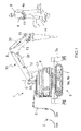
- Figure 1 shows a remote-controlled, electrically driven work machine 1 designed as a demolition robot that is supplied with power through a cable 2.
- the work machine requires energy, and in order to be able to supply this with the required electrical power the electricity distribution grid supplies a grid current of 32 A.
- the grid is equipped also with fuses in order to be able to satisfy such a power requirement.
- the reference number 2' is used to denote a cable from the electricity distribution grid that can supply only a limited grid current, in this case 16 A. It should thus be realised that this alternative electrical grid cannot supply the amount of energy that the work machine requires, and that any attempt to connect the work machine to the said second electrical grid and operate it, using the power cable 2', is futile, since the 16 A fuses would blow.
- a remote-controlled work machine of the present type is manufactured and sold under the trademark "BROKK", and at such a work machine an operator 3 walks beside the machine and controls and operates it by means of a portable control unit 4 or remote-control unit that is carried on the body by means of a belt or harness.
- the control unit 4 comprises two control levers, one of which 4a is located at the left and the other of which 4b is located at the right, and the control unit has a series of buttons and knobs that through their influence and settings can cause the work machine to carry out the desired motions, or through the input of data the work machine is provided with the required instructions.
- the work machine 1 generally comprises a chassis 5 with an upper part 6 and a lower part 7.
- the upper part 6 is mounted to rotate in bearings on the lower part 7 for oscillation in a horizontal plane around a vertical axis C.
- the lower part 7 of the work machine 1 is provided with a propulsion means 8a that includes continuous tracks 8b.
- the work machine has a number of support legs 7b for lifting the work machine from a surface.
- the work machine 1 that has been described is somewhat simplified and is illustrated with fewer components than is normal, in order to make the sketch clear.
- the work machine 1 has a manoeuvrable arm 10 that is supported at the rotatable upper part 6 and includes four hydraulic functions for the manoeuvring of the arm, which functions include, when viewed from the chassis of the work machine, pivoting of a number of mutually jointed arm sections 11, 12, 13.
- a tool 14 is attached at the end of the arm by what is known as a "quick-release coupling" 15.
- the said arm sections 11, 12, 13 pivot relative to each other around essentially horizontal axes A.
- the operator 3 is in connection with the work machine through the control unit 4 by cable or in a wireless manner, for example through Bluetooth or radio control.
- the work machine 1 can be set through the control unit 4 into different working modes as is illustrated in Figure 4B .
- the control unit 4 is set into what is known as "setup mode" during the exchange of the working mode. Exchange of working mode can take place only when the control unit 4 is in the said setup mode, whereby the selected working mode is displayed with the aid of symbols that are illuminated on a screen 4c or display on the control unit 4.
- the volume of flow of the hydraulic medium to the operational devices of the work machine is reduced in this power-limiting mode.
- the fact that the power-limiting mode has been activated, in the "On" mode is indicated on the display 4c of the control unit 4.
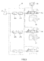
- FIG. 2 shows a circuit diagram 22 for a hydraulic system intended for the control of the work machine.
- the circuit diagram makes it clear that the work machine 1 is equipped with a three-phase electrical motor 19 that drives a hydraulic pump 20 with fixed displacement, and with which pump all of the operational devices of the machine are provided with hydraulic medium.
- a first hydraulic cylinder 30 the boom cylinder
- the second hydraulic cylinder 31 and the third hydraulic cylinder 32 the arm cylinders
- a fourth hydraulic cylinder 33 a breaker or pivot cylinder for the tool
- the reference number 23 generally denotes a regulator structure that is a component of the hydraulic system for the control of the operational devices 30, 31, 32, 33 of the work machine.
- the full lines denote hydraulic lines, while the dashed-dot lines in Figure 2 ] denote lines for electrical signals.
- the hydraulic pump 20 is arranged to supply the operational devices of the manoeuvrable arm 10 with hydraulic medium. It is the task of the first flow-regulating valve 21a of the hydraulic system 23 to regulate the hydraulic flow to a hydraulically powered tool, in this case a demolition hammer 14, and the valve is connected hydraulically to the pump 20 through a valve 24 that sets priorities, and electrically to a computer unit 25 that is a component of the CAN system.
- the valve 24 that sets priorities in the present embodiment is set to always give priority to the hydraulic flow to the tool (the hydraulic demolition hammer) before other consumers.
- the hydraulic system 23 comprises further a second flow-regulating valve 20b in the form of a manoeuvrable arm valve that is set to regulate the hydraulic flow to the operational devices of the work machine, i.e. to the first cylinder 31 (the boom cylinder), the second 32 and the third 33 arm cylinders, and the fourth cylinder 34 that constitutes the breaker or pivot cylinder for the supported tool 14.
- a slider (not shown in the drawings) that is a component of the relevant control valve 21a, 21b, it is possible to obtain a pre-determined flow out to an operational device through the lines.
- the slider is manoeuvred electrically and is displaced a pre-determined distance in the valve 21a, 21b when a lever 4a, 4b on the control unit 4 is operated.
- the displacement of the slider in the valve 21a, 21b is proportional to the displacement of the lever 4a, 4b.
- the computer unit 25 is connected to the said first and second control valves 21a, 21b for the regulation of these.
- the levers 4a, 4b, are connected to the computer unit 25, as is the control unit 4 in its entirety.
- the hydraulic system 23 is of the type that senses the load applied, and this means that the pump 20 supplies fluid only when it is required and only to the locations at which it is required.
- the volume of flow of the hydraulic medium to each control valve 21a, 21b is proportional to the displacement of the lever, and the possibility of controlling and regulating this proportionality in the hydraulic system 23 of CAN-type is described below in more detail.
- This selectable power mode with a reduced volume of hydraulic medium is obtained through parameter adjustment of the valve-control curves that are stored in the control computer 25 of the hydraulic system 23, such that the proportionality between displacement of a lever and the motion of a slider in the control valve 21a, 21b is experienced as normal by the operator, while involving the volume of flow of hydraulic medium to the operational devices being limited.
- the work machine 1 is placed into the reduced-power mode by means of selectable menus in the control unit 4.
- FIG. 3 shows the hydraulic system 23 in more detail and, as the drawing makes clear, the circuit diagram of electrohydraulic valve blocks is denoted by 22, which valve blocks, together with the control computer 25, control and regulate the motion of the first and second operational devices of the work machine, i.e. the first cylinder 30 (the boom cylinder) and the second arm cylinder 31.
- the electrical operation of the valves 21a, 21b is carried out by the computer unit 25.
- Any other hydraulic cylinders that are components of the manoeuvrable arm 10 are controlled in a similar manner by further valve sections in the block: one further block is suggested by dash-dot contour lines in Figure 3 .
- One of the two control levers 4a that are components of the control unit 4 forms a first signal transmitter of the commands of the operator to be sent to the computer unit 25.
- Control signals are produced by the electronic control lever 4a, which signals are led to the computer unit 25 and from this unit an amount of hydraulic flow that is predetermined by the valve-control curves 26a, 26b is transmitted to the relevant operational devices 30, 31 through the control valve 22b.
- the control lever 4a communicates with the control unit 22 and with relevant other components through an integrated CAN interface.
- parameterisation of the program functions can be carried out through the CAN interface, with, for example, a portable service computer connected to the control computer 25.
- Resetting the work machine 1 from normal operation to the operating condition in which power limitation is on is activated by the operator with the aid of the menus of the control unit 4, which commands are received through digital inputs at the control computer 25.
- the CAN signals and the commands at the digital inputs are processed in task and maintask, and they start and dismiss control routines in the control computer 25.
- the program routines control through PWM outputs proportional magnets in the electrohydraulic valves in the blocks 21, 21b.
- Valve control curves 26a, 26b are stored in the computer unit 25 in the form of software for each one of the relevant operational devices 30, 31 and for any other operational devices.
- control sequences for normal operation and for power-limiting operation are divided into two groups, namely one group with pre-programmed valve-control curves 26a, 26b for each relevant operational cylinder 31, 32.
- the motions are controlled based on the selected operating mode with the pre-programmed valve-control curves 26a, 26b for the relevant operational cylinder.
- correction factor curves 27a and 27b are available, the task of which is to adjust the parameters of the valve-control curves 26a, 26b by displacing these in a suitable manner such that the output flow of hydraulic medium from the control valves 22a, 22b is reduced in a pre-determined manner.
- the correction factor curves 27a, 27b are determined based on the calculated volume of flow that the hydraulic system can supply at a pre-determined maximal amount of available energy.
- the correction factor curves 27a, 27b compensate and correct the valve-control curves 26a, 26b such that the operational devices 30, 31 of the manoeuvrable arm, and any other devices present, can carry out their control and actuator motion with a limited volume of flow.
- FIG 4 shows using symbols the working modes into which the machine has been placed.
- the work machine 1 set into the position for mode selection of operating the work machine 1 at reduced power (“power-limiting")
- the symbol for selection of operating condition is displayed, whereby the display 4c is illuminated, and on activation of the function in its "On" mode, this is indicated of the display 4c of the control unit 4.
Landscapes
- Engineering & Computer Science (AREA)
- Mining & Mineral Resources (AREA)
- Civil Engineering (AREA)
- General Engineering & Computer Science (AREA)
- Structural Engineering (AREA)
- Physics & Mathematics (AREA)
- Fluid Mechanics (AREA)
- General Physics & Mathematics (AREA)
- Automation & Control Theory (AREA)
- Operation Control Of Excavators (AREA)
Abstract
Description
- The present invention concerns a control device for a remote-controlled, electrically driven work machine according to introduction till
claim 1. - A remote-controlled work machine of the present type generally includes a chassis with an upper part and a lower part. The upper part is mounted on bearings on the lower part in a manner that allows rotation, for oscillation in a horizontal plane around a vertical axis, and it supports a manoeuvrable arm that is provided at its end with a quick-release coupling for the support of various types of tool. The lower part of the work machine is provided with a propulsion means that includes continuous tracks. This type of work machine is intended for various types of task and for specific industrial applications, not only indoors but also outdoors. An operator walks beside the machine and controls its various movements with a control unit that is supported on the body of the operator by a harness or similar. The work machine has various types of working mode that can be selected through the control unit. The operator is in connection with the machine through the control unit by cable or in a wireless manner, for example through Bluetooth or radio control. The control unit comprises two control levers and a series of button and knobs that through their influence and settings can cause the drive units and the manoeuvrable arm of the work machine to carry out the desired motions. The work machine can be set into various functional or working modes through the control unit. Exchange of working mode takes place when the control unit is set into what is known as "setup mode", whereby the selected working mode is displayed with the aid of symbols that are illuminated on the control unit. By setting the work machine into various working modes, the work machine can carry out a number of different motions with only the two control levers. The work machine is powered by electricity and is supplied with power through a power cable that is connected to an electrical grid. Energy in the form of a hydraulic medium under pressure is distributed with the aid of an electrically powered pump to the various operational devices of the work machine through valves of the type known as "electrohydraulic" valves. It in normal that the standardised CAN-system (where "CAN" is an acronym for "Controller Area Network") is used for work machines of this type. The CAN-system is computer-based and uses an electrical control and monitoring system with a low-level protocol for nodes and modules, whereby communication between the units that are components of the hydraulic system takes place over bus-based connections. The electric motor that is used to drive the pump device of the work machine is normally of three-phase, low-voltage type, with a rated voltage of 380-500 V and a frequency or 50 or 60 Hz.
- To facilitate understanding of the following, it is reminded that the energy that is transferred by hydraulic systems is calculated in general as the fluid pressure P (N/m2) multiplied by the volume of flow Q (m3/s). The efficiency η of a hydraulic system is defined as the power output (Watt) divided by the power input, and for conventional systems this lies in the interval 0.90-0.75. Thus the hydraulic medium constitutes an energy carrier, whereby the pump is normally dimensioned based on the energy requirements of the various consumers, i.e. the energy required to drive the various operational devices of the work machine for setting and manoeuvring the machine parts will determine the dimensions of the hydraulic system. To this is added the energy requirements for driving a tool supported by the manoeuvrable arm, which means that the pump is normally selected, with respect to the total energy requirement of the work vehicle, with a suitable degree of excess capacity in order to be able to drive the tool.
- When the work machine is to be taken into use at the intended location, it is not seldom that the problem arises that the location in question lacks an electricity distribution grid for low voltage that can supply the required power to the work machine, i.e. the grid provides the required grid voltage, such as 380-400 V, but cannot supply the grid current that the work machine requires. For example, it is not seldom that the problem arises that the electricity distribution grid available at the location is limited such that it offers only a main fuse rating of 16 A while the work machine requires a considerably higher fuse rating, for example 32 A, in order for it to be possible to use it. Thus, starting to use the work machine is considerably delayed, or in the worst case made impossible, in those cases in which the electricity distribution grid at the location is assessed, quite simply, to be unable to supply the current required while following the safety requirements in force. It should be understood that it is extremely disruptive if the work machine cannot be taken into use at the location immediately, also in those cases in which it is possible to modify or adapt the electricity distribution grid such that it is able to supply the current required to the work machine. It should be understood that the requirement for greater grid current and thus higher fuse rating than the rating available at the relevant location of the electricity distribution grid not only involves increases in cost as such, but also places considerably greater demands on the external electrical grid, with demands on the required conductor area, protective conductors, etc., that is to provide current to the electricity distribution grid at the location.
- One purpose of the present invention, therefore, is to achieve a control arrangement for a remote-controlled work machine of the type described above that eliminates the problems described above and makes it possible to use the work machine at a work location immediately, also in those cases in which the electricity distribution grid at the location is not adapted to supply, nor has the capacity to supply, the current required. The purpose of the invention is achieved through the arrangement being given the features and characteristics that are specified in
claim 1. - The significant idea on which the invention is based consists of arranging for the hydraulic drive system of the work machine the possibility of two alternative operating conditions with the selection of an operating mode with a limited power whereby the volume of flow to the operational devices of the work machine is limited by adjusting the parameters of the control curves that the hydraulic system uses to regulate the opening of control valves for the passage of the flow of hydraulic fluid to the operational devices. As a result of the choice of operating mode with limited power, the work machine will function exactly as normally with the required working pressure in the hydraulic system, but the operational devices will carry out their control and actuator functions with a somewhat lower speed through the reduced volume of flow to the consumers.
- An embodiment of the invention will be described below in more detail with reference to the attached drawings, of which:
-
Figure 1 shows a side view of a remote-controlled, electrically driven work machine according to the invention that supports a tool at the end of its manoeuvrable arm in the form of a hydraulic hammer, and that is remotely controlled by an operator who walks next to the work machine, -
Figure 2 shows schematically a circuit diagram of a hydraulic system that is a component of a remotely controlled, electrically driven work machine according to the present invention, -
Figure 3 shows in more detail the functional principle of a hydraulic system that is a component of the present work machine and its associated regulating structure for the adjustment of parameters of the hydraulic control circuit of the work machine through selection of suitable valve-control curves in order to limit the volume of flow to the operational devices of the work machine, -
Figure 4A shows a perspective view from above of a control unit, such as it is seen by an operator during operation of the work machine, -
Figure 4B shows in the form of a summary the functions of the control unit in the working mode and symbols for setting the work machine from normal operation to an operating condition that has limited power. -
Figure 1 shows a remote-controlled, electrically drivenwork machine 1 designed as a demolition robot that is supplied with power through acable 2. The work machine requires energy, and in order to be able to supply this with the required electrical power the electricity distribution grid supplies a grid current of 32 A. The grid is equipped also with fuses in order to be able to satisfy such a power requirement. The reference number 2' is used to denote a cable from the electricity distribution grid that can supply only a limited grid current, in this case 16 A. It should thus be realised that this alternative electrical grid cannot supply the amount of energy that the work machine requires, and that any attempt to connect the work machine to the said second electrical grid and operate it, using the power cable 2', is futile, since the 16 A fuses would blow. - A remote-controlled work machine of the present type is manufactured and sold under the trademark "BROKK", and at such a work machine an
operator 3 walks beside the machine and controls and operates it by means of aportable control unit 4 or remote-control unit that is carried on the body by means of a belt or harness. Thecontrol unit 4 comprises two control levers, one of which 4a is located at the left and the other of which 4b is located at the right, and the control unit has a series of buttons and knobs that through their influence and settings can cause the work machine to carry out the desired motions, or through the input of data the work machine is provided with the required instructions. Thework machine 1 generally comprises achassis 5 with anupper part 6 and alower part 7. Theupper part 6 is mounted to rotate in bearings on thelower part 7 for oscillation in a horizontal plane around a vertical axis C. Thelower part 7 of thework machine 1 is provided with a propulsion means 8a that includescontinuous tracks 8b. The work machine has a number ofsupport legs 7b for lifting the work machine from a surface. - The
work machine 1 that has been described is somewhat simplified and is illustrated with fewer components than is normal, in order to make the sketch clear. Thework machine 1 has amanoeuvrable arm 10 that is supported at the rotatableupper part 6 and includes four hydraulic functions for the manoeuvring of the arm, which functions include, when viewed from the chassis of the work machine, pivoting of a number of mutually jointedarm sections tool 14 is attached at the end of the arm by what is known as a "quick-release coupling" 15. The saidarm sections - As is made most clear by
Figures 1 and4A , theoperator 3 is in connection with the work machine through thecontrol unit 4 by cable or in a wireless manner, for example through Bluetooth or radio control. Thework machine 1 can be set through thecontrol unit 4 into different working modes as is illustrated inFigure 4B . Thecontrol unit 4 is set into what is known as "setup mode" during the exchange of the working mode. Exchange of working mode can take place only when thecontrol unit 4 is in the said setup mode, whereby the selected working mode is displayed with the aid of symbols that are illuminated on a screen 4c or display on thecontrol unit 4. According to the present invention it is also possible to select in the said setup mode an operating condition with a power limitation, which condition can be activated by setting its mode to "On" or "Off". The volume of flow of the hydraulic medium to the operational devices of the work machine is reduced in this power-limiting mode. The fact that the power-limiting mode has been activated, in the "On" mode, is indicated on the display 4c of thecontrol unit 4. -
Figure 2 shows a circuit diagram 22 for a hydraulic system intended for the control of the work machine. The circuit diagram makes it clear that thework machine 1 is equipped with a three-phaseelectrical motor 19 that drives ahydraulic pump 20 with fixed displacement, and with which pump all of the operational devices of the machine are provided with hydraulic medium. In this simplified embodiment, only the first hydraulic cylinder 30 (the boom cylinder), the secondhydraulic cylinder 31 and the third hydraulic cylinder 32 (the arm cylinders) of themanoeuvrable arm 10, together with a fourth hydraulic cylinder 33 (a breaker or pivot cylinder for the tool) will be described in detail. Between eachoperational device pump 20 there is placed acontrol valve hydraulic pump 20 to the operational device such that the work machine can be manoeuvred in the desired manner through the influence of the twocontrol levers control unit 4, not only with respect to the motion of themanoeuvrable arm 10 but also with respect to driving thework machine 1 on its continuous tracks 8. Thereference number 23 generally denotes a regulator structure that is a component of the hydraulic system for the control of theoperational devices Figure 2 ] denote lines for electrical signals. As has been described above, thehydraulic pump 20 is arranged to supply the operational devices of themanoeuvrable arm 10 with hydraulic medium. It is the task of the first flow-regulatingvalve 21a of thehydraulic system 23 to regulate the hydraulic flow to a hydraulically powered tool, in this case ademolition hammer 14, and the valve is connected hydraulically to thepump 20 through avalve 24 that sets priorities, and electrically to acomputer unit 25 that is a component of the CAN system. Thevalve 24 that sets priorities in the present embodiment is set to always give priority to the hydraulic flow to the tool (the hydraulic demolition hammer) before other consumers. This means that if thedemolition hammer 14 and theoperational devices manoeuvrable arm 10 are used at the same time, it is the demolition hammer that will dominate, or that will have priority. The operational devices are activated slowly, and the manoeuvrable arm will move somewhat more slowly. This setting of priorities is previously known, and it is carried out fully hydraulically. - The
hydraulic system 23 comprises further a second flow-regulating valve 20b in the form of a manoeuvrable arm valve that is set to regulate the hydraulic flow to the operational devices of the work machine, i.e. to the first cylinder 31 (the boom cylinder), the second 32 and the third 33 arm cylinders, and the fourth cylinder 34 that constitutes the breaker or pivot cylinder for the supportedtool 14. Through the influence of a slider (not shown in the drawings) that is a component of therelevant control valve valve lever control unit 4 is operated. It should be understood that the displacement of the slider in thevalve lever computer unit 25 is connected to the said first andsecond control valves levers computer unit 25, as is thecontrol unit 4 in its entirety. Thehydraulic system 23 is of the type that senses the load applied, and this means that thepump 20 supplies fluid only when it is required and only to the locations at which it is required. As has been mentioned above, the volume of flow of the hydraulic medium to eachcontrol valve hydraulic system 23 of CAN-type is described below in more detail. It is, however, normally the case that the said levers give a hydraulic flow from thecontrol valves control computer 25 whereby valve-control curves stored in this computer determine the degree of opening of the sliders on the displacement of the levers. Just as usual, the displacement of thelevers hydraulic system 23 uses. The control curves can be so adapted that the proportionality between the displacement of the lever and the motion of the slider in thecontrol valve operational device - It has proved to be possible to solve the problems of inadequate electricity distribution grids and grids that cannot supply the required amount of energy for work machines of this type through achieving, by means of the software of the control system, an operating mode that can be selected by the operator, which operating mode offers lower power. With the work machine set in the mode with lower power, a displacement of the levers that is experienced by the operator as normal will result in the
control valves control computer 25 of thehydraulic system 23, such that the proportionality between displacement of a lever and the motion of a slider in thecontrol valve operator 3, thework machine 1 is placed into the reduced-power mode by means of selectable menus in thecontrol unit 4. -
Figure 3 shows thehydraulic system 23 in more detail and, as the drawing makes clear, the circuit diagram of electrohydraulic valve blocks is denoted by 22, which valve blocks, together with thecontrol computer 25, control and regulate the motion of the first and second operational devices of the work machine, i.e. the first cylinder 30 (the boom cylinder) and thesecond arm cylinder 31. The electrical operation of thevalves computer unit 25. Any other hydraulic cylinders that are components of themanoeuvrable arm 10 are controlled in a similar manner by further valve sections in the block: one further block is suggested by dash-dot contour lines inFigure 3 . One of the twocontrol levers 4a that are components of thecontrol unit 4 forms a first signal transmitter of the commands of the operator to be sent to thecomputer unit 25. Control signals are produced by theelectronic control lever 4a, which signals are led to thecomputer unit 25 and from this unit an amount of hydraulic flow that is predetermined by the valve-control curves operational devices control lever 4a communicates with thecontrol unit 22 and with relevant other components through an integrated CAN interface. In a similar manner, parameterisation of the program functions can be carried out through the CAN interface, with, for example, a portable service computer connected to thecontrol computer 25. Resetting thework machine 1 from normal operation to the operating condition in which power limitation is on is activated by the operator with the aid of the menus of thecontrol unit 4, which commands are received through digital inputs at thecontrol computer 25. The CAN signals and the commands at the digital inputs are processed in task and maintask, and they start and dismiss control routines in thecontrol computer 25. The program routines control through PWM outputs proportional magnets in the electrohydraulic valves in theblocks 21, 21b.Valve control curves computer unit 25 in the form of software for each one of the relevantoperational devices control curves operational cylinder control curves control curves control curves operational devices -
Figure 4 shows using symbols the working modes into which the machine has been placed. With thework machine 1 set into the position for mode selection of operating thework machine 1 at reduced power ("power-limiting"), the symbol for selection of operating condition is displayed, whereby the display 4c is illuminated, and on activation of the function in its "On" mode, this is indicated of the display 4c of thecontrol unit 4. - The present invention is not limited to what has been described above and shown in the drawings: it can be changed and modified in several different ways within the scope of the innovative concept defined by the attached patent claims.
Claims (5)
- A control device for a remote-controlled, electrically driven work machine (1) that can be driven such as a vehicle and that is supplied with power through an electrical cable (2, 2') intended to be connected to an electricity distribution grid, and which work machine comprises an arm (10) that can be manoeuvred in a vertical plane, which arm is rotatable for oscillation in a horizontal plane around a vertical axis (C) on the machine and is intended to support a tool (14) at its free end, a control unit (4) intended for the remote control of the work machine whereby an operator (3) walks beside the work machine and is in connection by cable or in a wireless manner with a control computer (25) that forms a part of a programmable hydraulic control system (22) that is a component of the work machine and that is based on a CAN bus, which hydraulic control system includes an electrically driven pump (19) and an electrically controlled control valve (21a, 21b) that supplies driving flow to the operational devices (30, 31, 32, 33) of the work machine, whereby the control unit includes a pair of control levers (4a, 4b) and buttons (4d, 4e) and knobs that through their influence allow the work machine to be set into various functional or working modes for the control levers, characterised in that the work machine can be reset from a normal operating mode to an operation mode with limited power, whereby the volume of flow of the hydraulic medium to the operational devices (30, 31, 32, 33) of the work machine is limited through parameter adjustment of the control curves (26a, 26b) that the programmable hydraulic system (22) that is based on a CAN bus uses to regulate the opening of the control valves (21a, 21b) for passage through them of hydraulic flow to the operational devices.
- The control device according to claim 1, whereby the parameter adjustment of the valve-control curves (26a, 26b) takes place through the influence of correction factor curves (27a, 27b) that are stored as software in the control computer (25).
- The control device according to any one of claims 1-2, whereby resetting from the normal operating mode for the work machine to an operating mode with limited power takes place directly through selectable menus and buttons (4d, 4e) in the control unit (4).
- The control device according to any one of claims 1-3, whereby the valve-control curves (26a, 26b) are so adapted that the proportionality between lever displacement and the motion of a slider that is a component of the control valve (21a, 21b) is modified by the influence of correction-factor curves (27a, 27b) such that the volume of flow of hydraulic medium that is supplied to the relevant operational device (30, 31, 32, 33) is reduced.
- The control device according to any one of claims 1-4, whereby the correction-factor curves (27a, 27b) that, stored as software in the control computer (25), are adapted such that they allow, when the operating mode with limited power is selected, a work machine to be connected and driven by an electrical supply grid that is fused only for a maximal output of sixteen (≤16 A) amps of grid current.
Applications Claiming Priority (1)
| Application Number | Priority Date | Filing Date | Title |
|---|---|---|---|
| SE1151042A SE536147C2 (en) | 2011-11-07 | 2011-11-07 | Control device for a remotely controlled, electrically operated work machine |
Publications (3)
| Publication Number | Publication Date |
|---|---|
| EP2589709A2 true EP2589709A2 (en) | 2013-05-08 |
| EP2589709A3 EP2589709A3 (en) | 2017-08-02 |
| EP2589709B1 EP2589709B1 (en) | 2023-08-02 |
Family
ID=47630066
Family Applications (1)
| Application Number | Title | Priority Date | Filing Date |
|---|---|---|---|
| EP12191290.1A Active EP2589709B1 (en) | 2011-11-07 | 2012-11-05 | Control device for a remote-controlled, electrically-driven work machine |
Country Status (2)
| Country | Link |
|---|---|
| EP (1) | EP2589709B1 (en) |
| SE (1) | SE536147C2 (en) |
Cited By (14)
| Publication number | Priority date | Publication date | Assignee | Title |
|---|---|---|---|---|
| CN105544642A (en) * | 2015-12-29 | 2016-05-04 | 徐州赫思曼电子有限公司 | Remote control system and method for small excavator |
| WO2017069689A1 (en) * | 2015-10-19 | 2017-04-27 | Husqvarna Ab | Automatic tuning of valve for remote controlled demolition robot |
| US20180305897A1 (en) * | 2015-10-19 | 2018-10-25 | Husqvarna Ab | Energy buffer arrangement and method for remote controlled demolition robot |
| US10422357B2 (en) | 2015-10-19 | 2019-09-24 | Husqvarna Ab | Adaptive control of hydraulic tool on remote controlled demolition robot |
| US10920436B2 (en) | 2016-06-09 | 2021-02-16 | Husqvarna Ab | Arrangement and method for operating a hydraulically operated boom carrying a tool in a carrier |
| CN112486094A (en) * | 2020-11-30 | 2021-03-12 | 哈尔滨工业大学(威海) | Cutter optimization and processing track generation method for complex curved surface side milling |
| US11029681B2 (en) * | 2019-03-04 | 2021-06-08 | Deere & Company | Semi-autonomous payload retrieval system |
| CN114434200A (en) * | 2021-12-27 | 2022-05-06 | 重庆长安新能源汽车科技有限公司 | High-safety-risk mechanical equipment safety protection method and system |
| EP3519237B1 (en) | 2016-09-29 | 2022-05-25 | Brokk AB | Power supply system and method for a dc-motor driving a hydraulic pump |
| WO2022171281A1 (en) * | 2021-02-11 | 2022-08-18 | Volvo Construction Equipment Ab | A gateway device comprising a hydraulic pressure release function |
| SE2150253A1 (en) * | 2021-03-04 | 2022-09-05 | Husqvarna Ab | An energy efficient hydraulic system for construction machines |
| DE102021204076A1 (en) | 2021-04-23 | 2022-10-27 | Volkswagen Aktiengesellschaft | Vehicle guidance system for a driverless controllable vehicle |
| CN115391930A (en) * | 2022-07-27 | 2022-11-25 | 三一重机有限公司 | Method, device and equipment for determining relation curve and working machine |
| WO2024068869A1 (en) | 2022-09-29 | 2024-04-04 | Husqvarna Ab | Construction equipment with advanced power management functions |
Family Cites Families (5)
| Publication number | Priority date | Publication date | Assignee | Title |
|---|---|---|---|---|
| DE602006006821D1 (en) * | 2005-05-27 | 2009-06-25 | Charles Machine Works | DETERMINING THE POSITION OF A REMOTE CONTROL USER |
| CN100591880C (en) * | 2006-12-31 | 2010-02-24 | 三一重工股份有限公司 | An intelligent boom control device |
| US8428791B2 (en) * | 2009-01-20 | 2013-04-23 | Husqvarna Ab | Control system for a remote control work machine |
| US9162558B2 (en) * | 2009-06-15 | 2015-10-20 | Polaris Industries Inc. | Electric vehicle |
| US8833066B2 (en) * | 2010-01-18 | 2014-09-16 | Illinois Tool Works Inc. | Low speed hydraulic control for fine control of hydraulic cranes |
-
2011
- 2011-11-07 SE SE1151042A patent/SE536147C2/en unknown
-
2012
- 2012-11-05 EP EP12191290.1A patent/EP2589709B1/en active Active
Non-Patent Citations (1)
| Title |
|---|
| "DXR 310", OPERATOR'S MANUAL, 29 December 2009 (2009-12-29), pages 1 - 56, XP055918768 |
Cited By (21)
| Publication number | Priority date | Publication date | Assignee | Title |
|---|---|---|---|---|
| US11162243B2 (en) | 2015-10-19 | 2021-11-02 | Husqvarna Ab | Energy buffer arrangement and method for remote controlled demolition robot |
| CN108138815A (en) * | 2015-10-19 | 2018-06-08 | 哈斯科瓦那股份公司 | It is remotely controlled the automatic adjustment of the valve of teardown of engine people |
| US20180305897A1 (en) * | 2015-10-19 | 2018-10-25 | Husqvarna Ab | Energy buffer arrangement and method for remote controlled demolition robot |
| US10422357B2 (en) | 2015-10-19 | 2019-09-24 | Husqvarna Ab | Adaptive control of hydraulic tool on remote controlled demolition robot |
| US10738442B2 (en) | 2015-10-19 | 2020-08-11 | Husqvarna Ab | Automatic tuning of valve for remote controlled demolition robot |
| WO2017069689A1 (en) * | 2015-10-19 | 2017-04-27 | Husqvarna Ab | Automatic tuning of valve for remote controlled demolition robot |
| CN105544642A (en) * | 2015-12-29 | 2016-05-04 | 徐州赫思曼电子有限公司 | Remote control system and method for small excavator |
| US10920436B2 (en) | 2016-06-09 | 2021-02-16 | Husqvarna Ab | Arrangement and method for operating a hydraulically operated boom carrying a tool in a carrier |
| EP3519237B1 (en) | 2016-09-29 | 2022-05-25 | Brokk AB | Power supply system and method for a dc-motor driving a hydraulic pump |
| US11029681B2 (en) * | 2019-03-04 | 2021-06-08 | Deere & Company | Semi-autonomous payload retrieval system |
| CN112486094B (en) * | 2020-11-30 | 2022-07-05 | 哈尔滨工业大学(威海) | Tool optimization and machining path generation method for side milling of complex surfaces |
| CN112486094A (en) * | 2020-11-30 | 2021-03-12 | 哈尔滨工业大学(威海) | Cutter optimization and processing track generation method for complex curved surface side milling |
| US20240106681A1 (en) * | 2021-02-11 | 2024-03-28 | Volvo Construction Equipment Ab | A gateway device comprising a hydraulic pressure release function |
| WO2022171281A1 (en) * | 2021-02-11 | 2022-08-18 | Volvo Construction Equipment Ab | A gateway device comprising a hydraulic pressure release function |
| WO2022186752A1 (en) * | 2021-03-04 | 2022-09-09 | Husqvarna Ab | An energy efficient hydraulic system for construction machines |
| SE2150253A1 (en) * | 2021-03-04 | 2022-09-05 | Husqvarna Ab | An energy efficient hydraulic system for construction machines |
| SE545533C2 (en) * | 2021-03-04 | 2023-10-17 | Husqvarna Ab | A hydraulic system for construction machines and a method for controlling the hydraulic system |
| DE102021204076A1 (en) | 2021-04-23 | 2022-10-27 | Volkswagen Aktiengesellschaft | Vehicle guidance system for a driverless controllable vehicle |
| CN114434200A (en) * | 2021-12-27 | 2022-05-06 | 重庆长安新能源汽车科技有限公司 | High-safety-risk mechanical equipment safety protection method and system |
| CN115391930A (en) * | 2022-07-27 | 2022-11-25 | 三一重机有限公司 | Method, device and equipment for determining relation curve and working machine |
| WO2024068869A1 (en) | 2022-09-29 | 2024-04-04 | Husqvarna Ab | Construction equipment with advanced power management functions |
Also Published As
| Publication number | Publication date |
|---|---|
| EP2589709B1 (en) | 2023-08-02 |
| EP2589709A3 (en) | 2017-08-02 |
| SE536147C2 (en) | 2013-05-28 |
| SE1151042A1 (en) | 2013-05-08 |
Similar Documents
| Publication | Publication Date | Title |
|---|---|---|
| EP2589709B1 (en) | Control device for a remote-controlled, electrically-driven work machine | |
| EP2508680B1 (en) | Control system for and including a remote-controlled working machine equipped with a manoeuvrable arm | |
| EP3519237B1 (en) | Power supply system and method for a dc-motor driving a hydraulic pump | |
| CN1299871C (en) | Method for connecting multiple welding devices and corresponding welding device | |
| CN101410767B (en) | Adjustor module for group valve | |
| EP2832567A1 (en) | Power-transmission device and hybrid construction equipment provided therewith | |
| EP2672127A1 (en) | Power regeneration device for work machine | |
| EP3147519A1 (en) | Hydraulic energy regeneration apparatus for machinery | |
| WO2019192669A1 (en) | A working machine, a work attachment and a combination thereof | |
| EP2716823A1 (en) | Electric drive system for construction machine | |
| JPH09105154A (en) | Control circuit of construction machine | |
| JP3105160U (en) | Mineral material processing equipment | |
| EP2684379B1 (en) | System for control of mobile hydraulic equipment | |
| EP2009279B1 (en) | Method for controlling of at least one element of a first component of a wind turbine, control device and use of the control device | |
| CN201191366Y (en) | Loading machine integrated controller | |
| CN114527696B (en) | Solenoid valve control system, method and operating machine | |
| JP2023117976A (en) | Electric excavator and management system | |
| GB2547869A (en) | Hydraulic drive system for construction machine | |
| US10780517B2 (en) | Hydraulically driven dual operator welding system and method | |
| CN114250818B (en) | Control method of multifunctional tool of excavator | |
| KR101328780B1 (en) | Hybrid regulator for main pump of excavator | |
| JP2023105757A (en) | Electric excavator air conditioning system, program, and electric excavator | |
| CN103122647B (en) | Remote control rotation system for excavator | |
| KR200393635Y1 (en) | Apparatus for multi-branch welding with controller | |
| CN223424000U (en) | Heading machine control system and heading machine |
Legal Events
| Date | Code | Title | Description |
|---|---|---|---|
| PUAI | Public reference made under article 153(3) epc to a published international application that has entered the european phase |
Free format text: ORIGINAL CODE: 0009012 |
|
| AK | Designated contracting states |
Kind code of ref document: A2 Designated state(s): AL AT BE BG CH CY CZ DE DK EE ES FI FR GB GR HR HU IE IS IT LI LT LU LV MC MK MT NL NO PL PT RO RS SE SI SK SM TR |
|
| AX | Request for extension of the european patent |
Extension state: BA ME |
|
| PUAL | Search report despatched |
Free format text: ORIGINAL CODE: 0009013 |
|
| AK | Designated contracting states |
Kind code of ref document: A3 Designated state(s): AL AT BE BG CH CY CZ DE DK EE ES FI FR GB GR HR HU IE IS IT LI LT LU LV MC MK MT NL NO PL PT RO RS SE SI SK SM TR |
|
| AX | Request for extension of the european patent |
Extension state: BA ME |
|
| RIC1 | Information provided on ipc code assigned before grant |
Ipc: E02F 9/22 20060101AFI20170629BHEP Ipc: E02F 9/20 20060101ALI20170629BHEP |
|
| STAA | Information on the status of an ep patent application or granted ep patent |
Free format text: STATUS: REQUEST FOR EXAMINATION WAS MADE |
|
| 17P | Request for examination filed |
Effective date: 20180126 |
|
| RBV | Designated contracting states (corrected) |
Designated state(s): AL AT BE BG CH CY CZ DE DK EE ES FI FR GB GR HR HU IE IS IT LI LT LU LV MC MK MT NL NO PL PT RO RS SE SI SK SM TR |
|
| STAA | Information on the status of an ep patent application or granted ep patent |
Free format text: STATUS: EXAMINATION IS IN PROGRESS |
|
| 17Q | First examination report despatched |
Effective date: 20210503 |
|
| TPAC | Observations filed by third parties |
Free format text: ORIGINAL CODE: EPIDOSNTIPA |
|
| GRAP | Despatch of communication of intention to grant a patent |
Free format text: ORIGINAL CODE: EPIDOSNIGR1 |
|
| STAA | Information on the status of an ep patent application or granted ep patent |
Free format text: STATUS: GRANT OF PATENT IS INTENDED |
|
| INTG | Intention to grant announced |
Effective date: 20230307 |
|
| RIN1 | Information on inventor provided before grant (corrected) |
Inventor name: DANIELSSON, ARNE Inventor name: BYSTEDT, GUNNAR |
|
| GRAS | Grant fee paid |
Free format text: ORIGINAL CODE: EPIDOSNIGR3 |
|
| GRAA | (expected) grant |
Free format text: ORIGINAL CODE: 0009210 |
|
| STAA | Information on the status of an ep patent application or granted ep patent |
Free format text: STATUS: THE PATENT HAS BEEN GRANTED |
|
| AK | Designated contracting states |
Kind code of ref document: B1 Designated state(s): AL AT BE BG CH CY CZ DE DK EE ES FI FR GB GR HR HU IE IS IT LI LT LU LV MC MK MT NL NO PL PT RO RS SE SI SK SM TR |
|
| REG | Reference to a national code |
Ref country code: GB Ref legal event code: FG4D |
|
| REG | Reference to a national code |
Ref country code: CH Ref legal event code: EP |
|
| REG | Reference to a national code |
Ref country code: DE Ref legal event code: R096 Ref document number: 602012079910 Country of ref document: DE |
|
| REG | Reference to a national code |
Ref country code: IE Ref legal event code: FG4D |
|
| REG | Reference to a national code |
Ref country code: LT Ref legal event code: MG9D |
|
| P01 | Opt-out of the competence of the unified patent court (upc) registered |
Effective date: 20231026 |
|
| REG | Reference to a national code |
Ref country code: NL Ref legal event code: MP Effective date: 20230802 |
|
| REG | Reference to a national code |
Ref country code: AT Ref legal event code: MK05 Ref document number: 1594891 Country of ref document: AT Kind code of ref document: T Effective date: 20230802 |
|
| PG25 | Lapsed in a contracting state [announced via postgrant information from national office to epo] |
Ref country code: GR Free format text: LAPSE BECAUSE OF FAILURE TO SUBMIT A TRANSLATION OF THE DESCRIPTION OR TO PAY THE FEE WITHIN THE PRESCRIBED TIME-LIMIT Effective date: 20231103 |
|
| PG25 | Lapsed in a contracting state [announced via postgrant information from national office to epo] |
Ref country code: IS Free format text: LAPSE BECAUSE OF FAILURE TO SUBMIT A TRANSLATION OF THE DESCRIPTION OR TO PAY THE FEE WITHIN THE PRESCRIBED TIME-LIMIT Effective date: 20231202 |
|
| PG25 | Lapsed in a contracting state [announced via postgrant information from national office to epo] |
Ref country code: SE Free format text: LAPSE BECAUSE OF FAILURE TO SUBMIT A TRANSLATION OF THE DESCRIPTION OR TO PAY THE FEE WITHIN THE PRESCRIBED TIME-LIMIT Effective date: 20230802 Ref country code: RS Free format text: LAPSE BECAUSE OF FAILURE TO SUBMIT A TRANSLATION OF THE DESCRIPTION OR TO PAY THE FEE WITHIN THE PRESCRIBED TIME-LIMIT Effective date: 20230802 Ref country code: PT Free format text: LAPSE BECAUSE OF FAILURE TO SUBMIT A TRANSLATION OF THE DESCRIPTION OR TO PAY THE FEE WITHIN THE PRESCRIBED TIME-LIMIT Effective date: 20231204 Ref country code: NO Free format text: LAPSE BECAUSE OF FAILURE TO SUBMIT A TRANSLATION OF THE DESCRIPTION OR TO PAY THE FEE WITHIN THE PRESCRIBED TIME-LIMIT Effective date: 20231102 Ref country code: NL Free format text: LAPSE BECAUSE OF FAILURE TO SUBMIT A TRANSLATION OF THE DESCRIPTION OR TO PAY THE FEE WITHIN THE PRESCRIBED TIME-LIMIT Effective date: 20230802 Ref country code: LV Free format text: LAPSE BECAUSE OF FAILURE TO SUBMIT A TRANSLATION OF THE DESCRIPTION OR TO PAY THE FEE WITHIN THE PRESCRIBED TIME-LIMIT Effective date: 20230802 Ref country code: LT Free format text: LAPSE BECAUSE OF FAILURE TO SUBMIT A TRANSLATION OF THE DESCRIPTION OR TO PAY THE FEE WITHIN THE PRESCRIBED TIME-LIMIT Effective date: 20230802 Ref country code: IS Free format text: LAPSE BECAUSE OF FAILURE TO SUBMIT A TRANSLATION OF THE DESCRIPTION OR TO PAY THE FEE WITHIN THE PRESCRIBED TIME-LIMIT Effective date: 20231202 Ref country code: HR Free format text: LAPSE BECAUSE OF FAILURE TO SUBMIT A TRANSLATION OF THE DESCRIPTION OR TO PAY THE FEE WITHIN THE PRESCRIBED TIME-LIMIT Effective date: 20230802 Ref country code: GR Free format text: LAPSE BECAUSE OF FAILURE TO SUBMIT A TRANSLATION OF THE DESCRIPTION OR TO PAY THE FEE WITHIN THE PRESCRIBED TIME-LIMIT Effective date: 20231103 Ref country code: FI Free format text: LAPSE BECAUSE OF FAILURE TO SUBMIT A TRANSLATION OF THE DESCRIPTION OR TO PAY THE FEE WITHIN THE PRESCRIBED TIME-LIMIT Effective date: 20230802 Ref country code: AT Free format text: LAPSE BECAUSE OF FAILURE TO SUBMIT A TRANSLATION OF THE DESCRIPTION OR TO PAY THE FEE WITHIN THE PRESCRIBED TIME-LIMIT Effective date: 20230802 |
|
| PG25 | Lapsed in a contracting state [announced via postgrant information from national office to epo] |
Ref country code: PL Free format text: LAPSE BECAUSE OF FAILURE TO SUBMIT A TRANSLATION OF THE DESCRIPTION OR TO PAY THE FEE WITHIN THE PRESCRIBED TIME-LIMIT Effective date: 20230802 |
|
| PG25 | Lapsed in a contracting state [announced via postgrant information from national office to epo] |
Ref country code: ES Free format text: LAPSE BECAUSE OF FAILURE TO SUBMIT A TRANSLATION OF THE DESCRIPTION OR TO PAY THE FEE WITHIN THE PRESCRIBED TIME-LIMIT Effective date: 20230802 |
|
| PG25 | Lapsed in a contracting state [announced via postgrant information from national office to epo] |
Ref country code: SM Free format text: LAPSE BECAUSE OF FAILURE TO SUBMIT A TRANSLATION OF THE DESCRIPTION OR TO PAY THE FEE WITHIN THE PRESCRIBED TIME-LIMIT Effective date: 20230802 Ref country code: RO Free format text: LAPSE BECAUSE OF FAILURE TO SUBMIT A TRANSLATION OF THE DESCRIPTION OR TO PAY THE FEE WITHIN THE PRESCRIBED TIME-LIMIT Effective date: 20230802 Ref country code: ES Free format text: LAPSE BECAUSE OF FAILURE TO SUBMIT A TRANSLATION OF THE DESCRIPTION OR TO PAY THE FEE WITHIN THE PRESCRIBED TIME-LIMIT Effective date: 20230802 Ref country code: EE Free format text: LAPSE BECAUSE OF FAILURE TO SUBMIT A TRANSLATION OF THE DESCRIPTION OR TO PAY THE FEE WITHIN THE PRESCRIBED TIME-LIMIT Effective date: 20230802 Ref country code: DK Free format text: LAPSE BECAUSE OF FAILURE TO SUBMIT A TRANSLATION OF THE DESCRIPTION OR TO PAY THE FEE WITHIN THE PRESCRIBED TIME-LIMIT Effective date: 20230802 Ref country code: CZ Free format text: LAPSE BECAUSE OF FAILURE TO SUBMIT A TRANSLATION OF THE DESCRIPTION OR TO PAY THE FEE WITHIN THE PRESCRIBED TIME-LIMIT Effective date: 20230802 Ref country code: SK Free format text: LAPSE BECAUSE OF FAILURE TO SUBMIT A TRANSLATION OF THE DESCRIPTION OR TO PAY THE FEE WITHIN THE PRESCRIBED TIME-LIMIT Effective date: 20230802 |
|
| REG | Reference to a national code |
Ref country code: DE Ref legal event code: R097 Ref document number: 602012079910 Country of ref document: DE |
|
| PG25 | Lapsed in a contracting state [announced via postgrant information from national office to epo] |
Ref country code: IT Free format text: LAPSE BECAUSE OF FAILURE TO SUBMIT A TRANSLATION OF THE DESCRIPTION OR TO PAY THE FEE WITHIN THE PRESCRIBED TIME-LIMIT Effective date: 20230802 |
|
| PLBE | No opposition filed within time limit |
Free format text: ORIGINAL CODE: 0009261 |
|
| STAA | Information on the status of an ep patent application or granted ep patent |
Free format text: STATUS: NO OPPOSITION FILED WITHIN TIME LIMIT |
|
| REG | Reference to a national code |
Ref country code: CH Ref legal event code: PL |
|
| PG25 | Lapsed in a contracting state [announced via postgrant information from national office to epo] |
Ref country code: MC Free format text: LAPSE BECAUSE OF FAILURE TO SUBMIT A TRANSLATION OF THE DESCRIPTION OR TO PAY THE FEE WITHIN THE PRESCRIBED TIME-LIMIT Effective date: 20230802 |
|
| 26N | No opposition filed |
Effective date: 20240503 |
|
| PG25 | Lapsed in a contracting state [announced via postgrant information from national office to epo] |
Ref country code: LU Free format text: LAPSE BECAUSE OF NON-PAYMENT OF DUE FEES Effective date: 20231105 |
|
| PG25 | Lapsed in a contracting state [announced via postgrant information from national office to epo] |
Ref country code: CH Free format text: LAPSE BECAUSE OF NON-PAYMENT OF DUE FEES Effective date: 20231130 |
|
| PG25 | Lapsed in a contracting state [announced via postgrant information from national office to epo] |
Ref country code: MC Free format text: LAPSE BECAUSE OF FAILURE TO SUBMIT A TRANSLATION OF THE DESCRIPTION OR TO PAY THE FEE WITHIN THE PRESCRIBED TIME-LIMIT Effective date: 20230802 Ref country code: LU Free format text: LAPSE BECAUSE OF NON-PAYMENT OF DUE FEES Effective date: 20231105 Ref country code: CH Free format text: LAPSE BECAUSE OF NON-PAYMENT OF DUE FEES Effective date: 20231130 Ref country code: SI Free format text: LAPSE BECAUSE OF FAILURE TO SUBMIT A TRANSLATION OF THE DESCRIPTION OR TO PAY THE FEE WITHIN THE PRESCRIBED TIME-LIMIT Effective date: 20230802 |
|
| REG | Reference to a national code |
Ref country code: BE Ref legal event code: MM Effective date: 20231130 |
|
| REG | Reference to a national code |
Ref country code: IE Ref legal event code: MM4A |
|
| PG25 | Lapsed in a contracting state [announced via postgrant information from national office to epo] |
Ref country code: IE Free format text: LAPSE BECAUSE OF NON-PAYMENT OF DUE FEES Effective date: 20231105 |
|
| PG25 | Lapsed in a contracting state [announced via postgrant information from national office to epo] |
Ref country code: BE Free format text: LAPSE BECAUSE OF NON-PAYMENT OF DUE FEES Effective date: 20231130 |
|
| PG25 | Lapsed in a contracting state [announced via postgrant information from national office to epo] |
Ref country code: IE Free format text: LAPSE BECAUSE OF NON-PAYMENT OF DUE FEES Effective date: 20231105 Ref country code: BE Free format text: LAPSE BECAUSE OF NON-PAYMENT OF DUE FEES Effective date: 20231130 |
|
| PG25 | Lapsed in a contracting state [announced via postgrant information from national office to epo] |
Ref country code: BG Free format text: LAPSE BECAUSE OF FAILURE TO SUBMIT A TRANSLATION OF THE DESCRIPTION OR TO PAY THE FEE WITHIN THE PRESCRIBED TIME-LIMIT Effective date: 20230802 |
|
| PG25 | Lapsed in a contracting state [announced via postgrant information from national office to epo] |
Ref country code: BG Free format text: LAPSE BECAUSE OF FAILURE TO SUBMIT A TRANSLATION OF THE DESCRIPTION OR TO PAY THE FEE WITHIN THE PRESCRIBED TIME-LIMIT Effective date: 20230802 |
|
| PG25 | Lapsed in a contracting state [announced via postgrant information from national office to epo] |
Ref country code: CY Free format text: LAPSE BECAUSE OF FAILURE TO SUBMIT A TRANSLATION OF THE DESCRIPTION OR TO PAY THE FEE WITHIN THE PRESCRIBED TIME-LIMIT; INVALID AB INITIO Effective date: 20121105 |
|
| PG25 | Lapsed in a contracting state [announced via postgrant information from national office to epo] |
Ref country code: HU Free format text: LAPSE BECAUSE OF FAILURE TO SUBMIT A TRANSLATION OF THE DESCRIPTION OR TO PAY THE FEE WITHIN THE PRESCRIBED TIME-LIMIT; INVALID AB INITIO Effective date: 20121105 |
|
| PGFP | Annual fee paid to national office [announced via postgrant information from national office to epo] |
Ref country code: GB Payment date: 20250916 Year of fee payment: 14 |
|
| PGFP | Annual fee paid to national office [announced via postgrant information from national office to epo] |
Ref country code: FR Payment date: 20250918 Year of fee payment: 14 |
|
| PG25 | Lapsed in a contracting state [announced via postgrant information from national office to epo] |
Ref country code: TR Free format text: LAPSE BECAUSE OF FAILURE TO SUBMIT A TRANSLATION OF THE DESCRIPTION OR TO PAY THE FEE WITHIN THE PRESCRIBED TIME-LIMIT Effective date: 20230802 |
|
| PGFP | Annual fee paid to national office [announced via postgrant information from national office to epo] |
Ref country code: DE Payment date: 20251014 Year of fee payment: 14 |