EP2589533B1 - Rotorsystem mit Antidrehverschleissschutz - Google Patents
Rotorsystem mit Antidrehverschleissschutz Download PDFInfo
- Publication number
- EP2589533B1 EP2589533B1 EP11192679.6A EP11192679A EP2589533B1 EP 2589533 B1 EP2589533 B1 EP 2589533B1 EP 11192679 A EP11192679 A EP 11192679A EP 2589533 B1 EP2589533 B1 EP 2589533B1
- Authority
- EP
- European Patent Office
- Prior art keywords
- clevis
- clip
- rotation
- axis
- flanges
- Prior art date
- Legal status (The legal status is an assumption and is not a legal conclusion. Google has not performed a legal analysis and makes no representation as to the accuracy of the status listed.)
- Active
Links
Images


Classifications
-
- B—PERFORMING OPERATIONS; TRANSPORTING
- B64—AIRCRAFT; AVIATION; COSMONAUTICS
- B64C—AEROPLANES; HELICOPTERS
- B64C27/00—Rotorcraft; Rotors peculiar thereto
- B64C27/54—Mechanisms for controlling blade adjustment or movement relative to rotor head, e.g. lag-lead movement
- B64C27/58—Transmitting means, e.g. interrelated with initiating means or means acting on blades
- B64C27/59—Transmitting means, e.g. interrelated with initiating means or means acting on blades mechanical
- B64C27/605—Transmitting means, e.g. interrelated with initiating means or means acting on blades mechanical including swash plate, spider or cam mechanisms
Definitions
- the present application relates generally to anti-rotation devices used to prevent wear in the rotating control systems of helicopters and tilt rotor aircraft and, more particularly, to a method and apparatus for limiting the rotation of an actuator rod used to manipulate the non-rotating swashplate of a swashplate system.
- Tilt rotor aircraft are hybrids between traditional helicopters and traditional propeller driven aircraft.
- Typical tilt rotor aircraft have fixed wings that terminate with convertible tilt rotor assemblies that house the engines and transmissions that drive the rotors.
- Tilt rotor aircraft are convertible from a helicopter mode, in which the tilt rotor aircraft can take-off, hover, and land like a helicopter; to an airplane mode, in which the tilt rotor aircraft can fly forward like a fixed-wing aircraft.
- a rotating control system typically consists of a rotating swashplate and a non-rotating swashplate connected by a bearing system.
- the rotating swashplate tracks the movements of the non-rotating swashplate, and the angle of the main rotor blades are adjusted accordingly.
- the non-rotating swashplate is manipulated by the pilot by way of hydraulic actuators.
- Each actuator rod is attached to one of several clevises of the non-rotating swashplate at a spherical bearing.
- the spherical bearing is held in place by a bearing housing at the end of the actuator rod.
- the spherical bearing permits rotational misalignment of the actuator in all axes.
- the misalignment of the spherical bearing is determined and controlled by inputs from the flight control system. Rotation of the actuator about its own longitudinal axis is not restricted, nor can it be limited or controlled by inputs from the flight control system. Because of this condition, the bearing housing is able to rotate within the clevis such that it comes into contact with an inner surface of the clevis. Such contact causes wear resulting in structural damage to both the clevis arms and the bearing housing. Since the clevis arms are integral to the non-rotating swashplate, damage to the clevis arms compromises the structural integrity of the non-rotating swashplate.
- Damage to the non-rotating swashplate causes a hazardous condition that could cause a pilot to loose control of the helicopter or aircraft.
- Devices have been inserted into the clevis to limit excessive rotation of the actuator. Such devices have caused premature wear and damage to the bearing housings from the introduction of debris, thereby compromising the structural integrity of the actuator.
- US patent application number 6, 371, 681 describes an anti rotation clip that is disposed between the clevis arms of each clevis of the non rotating swashplate.
- the anti-rotation clip is either of unitary or multi-piece construction.
- the anti-rotation clip includes a wall portion and at least one restraining member that protrudes inwardly from the wall portion. The restraining members limit the rotation of the actuator rod about the rod axis.
- US patent application number US2010 0047010 describes a self anti-rotation clip for a spherical-bearing rod end having two opposing spacer plates, each spacer plate having a curved edge portion for surrounding at least a portion of a ball of the rod end.
- a connector plate connects the spacer plates, such that the spacer plates are spaced from each other and generally parallel to each other.
- Retaining means are carried on the clip and adapted for retaining each spacer plate in a position generally adjacent one side of a body of the rod end, such that the spacer plates are free from interference with the ball of the rod end.
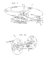
- Helicopter 11 having an anti-rotation device for use with a swashplate system 41 is illustrated.
- Helicopter 11 has an airframe 13, a main rotor assembly 15 including main rotor blades 17 and a main rotor shaft 18, and a tail rotor assembly 19 including tail rotor blades 21 and a tail rotor shaft 20.
- Main rotor blades 17 generally rotate about a longitudinal axis 16 of main rotor shaft 18.
- Tail rotor blades 21 generally rotate about a longitudinal axis 22 of tail rotor shaft 20.
- Helicopter 11 can take-off, hover, rotate, fly with a designated heading, and land.
- Helicopter 11 includes an anti-rotation device 12, according to the present application, for use in conjunction with swashplate system 41. Although hidden from view in Figure 1 , it is understood that anti-rotation device 12 and swashplate system 41 are located generally with respect to helicopter 11.
- Tilt rotor aircraft 23 able to perform similar functions to that of helicopter 11, is illustrated.
- Tilt rotor aircraft 23 has an airframe 25 and wings 27a and 27b coupled to airframe 25.
- wings 27a and 27b terminate with tilt rotor assemblies 29a and 29b, respectively.
- Tilt rotor assemblies 29a and 29b each generally include an engine, a transmission and gear box for driving rotor shafts 31a and 31b and prop-rotors 33a and 33b, and a conversion actuator for actuating tilt rotor assemblies 29a and 29b between an airplane mode, as illustrated in Figure 2A , and a helicopter mode, as illustrated in Figure 2B .
- tilt rotor aircraft 23 can be flown and operated like a conventional fixed-wing propeller driven aircraft. In the helicopter mode, tilt rotor aircraft 23 can take-off, hover, land, and be operated like a conventional rotary wing aircraft or helicopter. Tilt rotor aircraft 23 includes anti-rotation device 12 according to the present application for use in conjunction with swashplate system 41. Although hidden from view in Figure 1 , it is understood that anti-rotation device 12 and swashplate system 41 are located generally with respect to tilt rotor aircraft 23.
- a rotating control system, or swashplate system 41 for use in both helicopter 11 and tilt rotor aircraft 23 is illustrated.
- Swashplate system 41 can be either of original manufacture or an existing swashplate system that is being used on an aircraft.
- swashplate system 41 design varies, swashplate system 41 uses at least one hydraulic actuator 43 to manipulate a non-rotating swashplate 45.
- Non-rotating swashplate 45 includes a plurality of clevises 46, each clevis 46 formed by a pair of clevis arms 46a.
- Clevis arms 46a are adapted to pivotally receive hydraulic actuator 43.
- the position of hydraulic actuator 43 is determined by a pilot input during typical flight maneuvers.
- hydraulic actuator 43 pivotally operates within clevis arms 46a
- hydraulic actuator 43 is susceptible to contacting a portion of non-rotating swashplate 45.
- the contact can cause premature wear to non-rotating swashplate 45 and/or hydraulic actuator 43.
- Swashplate system 41 uses at least one anti-rotation device 12 to limit the rotational freedom of hydraulic actuator 43 in clevis 46a, 46b without limiting misalignment capability of hydraulic actuator 43. Contact and premature wear between hydraulic actuator 43 and non-rotating swashplate 45 is prevented.
- Non-rotating swashplate 45 is free to rotate about any horizontal, in-plane axis that intersects a longitudinal axis 48 of rotor shaft 50, whereby rotor shaft 50 is similar to main rotor shaft 18 ( Figure 1 ), tail rotor shaft 20 ( Figure 1 ), and rotor shafts 31a and 31b ( Figures 2A and 2B ). Such rotation will be referred to herein as "out-of-plane" rotation. Hydraulic actuator 43 causes non-rotating swashplate 45 to experience out-of-plane rotation, which causes a rotating swashplate 47 to experience the same out-of-plane rotation.
- Rotating swashplate 47 is also free to rotate in a plane parallel to non-rotating swashplate 45 about longitudinal axis 48. Such rotation shall be referred to herein as "in-plane” rotation.
- a bearing system 49 is disposed between rotating swashplate 47 and non-rotating swashplate 45.
- Rotating swashplate 47 includes a plurality of clevises 52, each clevis 52 formed by a pair of clevis arms 52a. Clevis arms 52a are adapted to pivotally receive a pitch link 51 for each of a plurality of main rotor blades 55.
- non-rotating swashplate 45 and rotating swashplate 47 experience out-of-plane rotation.
- the out-of-plane rotation by rotating swashplate 47 manipulates pitch link 51 connected to a pitch horn 53 for each of a plurality of main rotor blades 55.
- Pitch horn 53 extends or retracts based on the out-of-plane rotation of rotating swashplate 47, thereby adjusting an angle a of main rotor blade 55.
- Clip 65 is one of many embodiments of anti-rotation device 12.
- Clip 65 is a multipart device having at least a top, or first portion 67 and a bottom, or second portion 69.
- top portion 67 is identical in form and function to bottom portion 69.
- top portion 67 and bottom portion 69 are made from a plastic having good wear resistance, such as Nylatron.
- Nylatron refers to a family of plastics typically filled with molybdenum disulfide lubricant powder.
- the material composition of anti-rotation clip 65 could be any wear resistant material.
- Restraining member 97 is chosen such that the material of restraining member 97 is softer than the material used in hydraulic actuator 43 so as to promote wear on restraining member 97 rather than hydraulic actuator 43.
- Top portion 67 includes a generally rectangular center channel 71 having a bottom surface 73, a rear surface 75, and a top surface 77. Bottom surface 73 of center channel 71 of top portion 67 is adapted to mate with the corresponding bottom surface 73 of center channel 71 of bottom portion 69. Center channel 71 includes a longitudinally extending aperture 79 that extends from top surface 77 to bottom surface 73 along a longitudinal axis 81.
- a flange 83 extends rearward from rear surface 75 of center channel 71.
- Flange 83 includes a lower flange surface 84 that is generally tapered toward top surface 77 as lower flange surface 84 extends rearwardly from center channel 71.
- Top portion 67 also includes a side member 85.
- Side member 85 includes a planar portion 85a that is generally perpendicular to rear surface 75.
- Side member 85 also includes a generally rounded corner portion 85b that is integrated with planar portion 85a. Corner portion 85b is integrated with and flushly connected to rear surface 75.
- planar portion 85a is shown to be generally perpendicular to rear surface 75, it should be understood that planar portion 85a may form angles other than right angles with rear surface 75 depending on the angle of the clevis into which clip 65 is installed, as will be explained in more detail below.
- Planar portion 85a includes an arcuate cutout 93 forming legs 95a and 95b, leg 95a having an upper leg surface 99 and leg 95b having a lower leg surface 101. Upper leg surface 99 and lower leg surface 101 taper toward one another as planar portion 85a extends outward from corner portion 85b.
- a wall portion 87 is formed that is made up of both center channels 71 and both side members 85.
- Wall portion 87 includes an inner surface 89 and an opposing outer surface 91.
- Inner surface 89 includes a restraining member 97 that protrudes inwardly from inner surface 89 and perpendicular to axis of symmetry 135 (see Figure 5A ), thereby forming a relatively smooth and continuous bulbous portion.
- Restraining member 97 extends parallel to longitudinal axis 81, rather than perpendicular.
- Restraining member 97 includes a broad width between wall portion 87 and arcuate cutout 93. The width may vary.
- Restraining member 97 is configured to increase the surface contact with hydraulic actuator 43 to minimize potential wear to hydraulic actuator 43.
- Restraining member 97 is generally rectangular in cross section, although this shape could vary according to the application in which the apparatus is used. It is understood that restraining member 97 is not limited in size or shape to that depicted in the drawings. Restraining member 97 may extend as one continuous arc from upper leg surface 99 to lower leg surface 101. Furthermore, it is understood that one or more restraining members 97 may be used on each portion 67, 69. The location of restraining member 97 is selected in order to most effectively limit the rotational freedom of hydraulic actuator 43 without limiting misalignment capability of hydraulic actuator 43.
- Restraining member 97 is integrally formed within portion 67, 69.
- Other embodiments may configure restraining members 97 to releasably couple to portions 67, 69 so as to permit removal. Furthermore, such a method of removal allows portions 67, 69 to remain secured within swashplate system 41 during removal of restraining member 97.
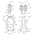
- top portion 67 and bottom portion 69 are illustrated. Bottom surfaces 73 of each center channel 71 are adapted to mate with the other.
- a connecting member 105 passes through apertures 79 to releasably join top portion 67 and bottom portion 69.
- the use of a multipart clip 65 allows clip 65 to be easily installed during original installation and easily replaced during periodic maintenance periods.
- An interfacing surface 103 is illustrated on restraining member 97 ( Figures 4A and 4B ) to represent the approximate contact area between hydraulic actuator 43 and restraining member 97 when hydraulic actuator 43 is at a maximum misalignment angle.
- the contour and shape of restraining member 97 is optimized to provide the largest interfacing surface 103 as possible across the range of orientations of hydraulic actuator 43. It is understood that interfacing surface 103 is representative only. Any portion of restraining member 97 may contact hydraulic actuator 43.
- the broad profile of restraining member 97 is configured to avoid localized wearing of hydraulic actuator 43 from the introduction of foreign abrasive matter and grease collecting at interfacing surfaces 103.
- Figures 5A and 5B illustrate a non-rotating swashplate 111 having an upper surface 113 and a lower surface 115.
- Swashplate 111 is similar to non-rotating swashplate 45.
- Non-rotating swashplate 111 also includes clevis arms 117a and 117b which are preferably parallel and form a typically U-shaped clevis 119. Although clevis arms 117a and 117b are shown as being parallel, it is not necessary that clevis arms 117a and 117b be parallel.
- clevis arms 117a and 117b extend outward from non-rotating swashplate 111 in a common clevis plane.
- An axis of symmetry 135 is disposed in the clevis plane between clevis arms 117a and 117b.
- Non-rotating swashplate 111 includes a clevis 119 for each rotor blade 55 (see Figure 3 ).
- Clevis 119 includes an inner surface 121.
- Clevis arm 117a includes an aperture 123a passing therethrough that is aligned with a corresponding aperture (not shown) passing through clevis arm 117b.
- Aperture 123a and the corresponding aperture through clevis arm 117b contain conventional bushings 125a and 125b which are adapted to engage a conventional spherical bearing 127 at the end of an actuator rod 129.
- Spherical bearing 127 allows rotational misalignment of actuator rod 129 in all axes.
- Spherical bearing 127 is radially constrained by a bearing housing 131 located at the end of actuator rod 129.
- a connecting pin 133 passes through aperture 123a, spherical bearing 127, and the corresponding aperture through clevis arm 117b, thereby pivotally attaching actuator rod 129 to non-rotating swashplate 111.
- Clip 65 is installed between clevis arms 117a and 117b.
- outer surface 91 of clip 65 is adapted to mate with inner surface 121 of clevis 119 by the use of an adhesive, such as a silicone adhesive.
- Legs 95a and 95b are adapted to concentrically surround bushings 125a and 125b.
- Lower flange surfaces 84 of flanges 83 of clip 65 are adapted to mate with upper surface 113 and lower surface 115 of non-rotating swashplate 111.
- Flanges 83 can be adapted to prevent translation of clip 65 along longitudinal axis 81. However, this is not a necessary feature of flanges 83.
- anti-rotation clip 65 is installed in clevis 119 of non-rotating swashplate 111.
- Actuator rod 129 part of hydraulic actuator 43, that includes spherical bearing 127 and bearing housing 131, is fastened between clevis arms 117a and 117b.
- Actuator rod 129 defines a rod axis 136 which extends axially along actuator rod 129.
- actuator rod 129 Upon input from the pilot, actuator rod 129 extends or retracts which causes out-of-plane rotation of non-rotating swashplate 111.
- the primary function of clip 65 is to limit the rotation of actuator rod 129 about rod axis 136, thereby eliminating or substantially reducing wear and structural damage.
- Restraining members 97 limit the rotation of actuator rod 129 about rod axis 136, while allowing actuator rod 129 to rotate about axis of symmetry 135.
- restraining members 97 allow actuator rod 129 to rotate about axis of symmetry 135 up to an angle ß. This rotation is necessary for proper manipulation of non-rotating swashplate 111, but the limitation of rotation about rod axis 136 prevents bearing housing 131 from impacting non-rotating swashplate 111.
- Angle ß varies according to the overall control system design. As seen in Figure 5C , bearing housing 131 may contact both restraining members 97 simultaneously.
- Clip 201 is another embodiment of anti-rotation device 12. More particularly, clip 201 is similar in form and function to that of clip 65, except as noted herein. Unlike the preferred embodiment, clip 201 is made of unitary construction. Furthermore, clip 201 does not include the use of center channel 71 or restraining member 97. Clip 201 is preferably made from Nylatron. However, the material composition of clip 201 could be any wear resistant material.
- Clip 201 is made of unitary construction unlike clip 65.
- Clip 201 is formed of a single body 203 made up of a back member 205 and a plurality of side members 207.
- Back member 205 and side members 207 are integrally coupled together by a generally rounded corner portion 208 that is integrated with and flushly connected to side member 207 and back member 205.
- body 203 includes an inner surface 209 and an opposing outer surface 211.
- Side member 207 is generally perpendicular to back member 205.
- side member 207 is shown to be generally perpendicular to back member 205, it should be understood that side member 207 may form angles other than right angles with back member 205 depending on the angle of the clevis into which clip 201 is installed, as will be explained in more detail below.
- Side member 207 includes an arcuate cutout 213 forming legs 215a and 215b, leg 215a having an upper leg surface 217 and leg 215b having a lower leg surface 219.
- Upper leg surface 217 and lower leg surface 219 taper toward one another as side member 207 extends outward from corner portion 208.
- Clip 201 is installed between clevis arms 117a and 117b. As explained previously, outer surface 211 of clip 201 is adapted to mate with inner surface 121 of clevis 119, as seen in Figure 5A , by the use of an adhesive, such as a silicone adhesive. Legs 215a and 215b are adapted to concentrically surround bushings 125a and 125b.
- clip 201 is installed in clevis 119 of non-rotating swashplate 111 as seen in Figure 5A .
- Actuator rod 129 which includes spherical bearing 127 and bearing housing 131, is fastened between clevis arms 117a and 117b.
- Actuator rod 129 defines a rod axis 136 which extends axially along actuator rod 129.
- actuator rod 129 Upon input from the pilot, actuator rod 129 extends or retracts which causes out-of-plane rotation of non-rotating swashplate 111.
- the primary function of clip 201 is to eliminate or substantially reduce wear and structural damage due to the impact of bearing housing 131 and inner surface 121 of clevis 119.
- Horse shoe insert 201 provides a barrier of protection around inner surface 121 of clevis 119.
- Actuator rod 129 is allowed to rotate about axis of symmetry 135 and rod axis 136. As shown in Figure 5C , actuator rod 129 is allowed to rotate about axis of symmetry 135 up to angle 13. This rotation is necessary for proper manipulation of non-rotating swashplate 111, but the barrier of protection provided by clip 201 prevents bearing housing 131 from impacting non-rotating swashplate 111.
- Angle ß varies according to the overall control system design.
- a clip 301 is another embodiment of anti-rotation device 12.
- Clip 301 is preferably made from Nylatron.
- the material composition of clip 301 could be any wear resistant material.
- Clip 301 has the same purposes, limitations, functions and features of the previous embodiments, therefore all such purposes, limitations, functions and features are incorporated herein except as described below.
- Clip 301 can be easily installed during original installation and easily replaced during periodic maintenance periods.
- Clip 301 may be manufactured as a unitary or multi-piece clip.
- Clip 301 is depicted as having two support members 303. When clip 301 is a multi-piece clip, each support member 303 is configured to have the same functions, features, and limitations.
- Clip 301 is configured to wrap around an upper portion of actuator rod 129 and extend one or more restraining members 305 toward and along bearing housing 131, below spherical bearing 127.
- Rod axis 136 of actuator rod 129 extends axially along actuator rod 129, as seen in Figures 5C and 6E .
- actuator rod 129 Upon input from the pilot, actuator rod 129 extends or retracts which causes out-of-plane rotation of non-rotating swashplate 111.
- Support member 303 has a band 307, a neck 313, and restraining member 305.
- Band 307 is formed in a relatively semi-circular shape having at least two ends. At each end is an aperture 309.
- Aperture 309 defines an axis 306.
- Aperture 309 is configured to accept a fastener 311 along axis 306.
- Clip 301 includes fastener 311 to secure a plurality of support members 303 around actuator rod 129, by interference fit when fasteners 311 are tightened.
- Each support member 303 is configured to align with an adjacent support member 303 along axis 306. Bands 307 contact and mate with an upper portion of actuator rod 129. Bands 307 of each support member 303 are coupled together with fasteners 311. When coupled together, bands 307 of clip 301 form a relatively circular shape that defines an axis 312. Axis 312 is configured to concentrically align with rod axis 136. Support members 303 define a plane 315 along a top surface 310.
- band 307 not all portions of band 307 are configured to mate with actuator rod 129 and bearing housing 131.
- Band 307 has a notch 314 with a notch surface 316.
- Notch 314 extends internally from an inner surface 308 of band 307. The distance which notch 314 extends within band 307 is dependent on the size and shape of actuator rod 129.
- notch surface 316 on each support member 303 presses against actuator rod 129.
- Notch surface 316 is shaped so as to accept actuator rod 129.
- Other portions of band 307 are not directly configured to mate with actuator rod 129. However, other embodiments may create one or more notches around band 307 to provide multiple mating locations to actuator rod 129.
- Restraining member 305 is coupled to band 307 by neck 313.
- Neck 313 is an elongated material integrally coupled to restraining member 305.
- band 307 is integrally coupled to neck 313, thereby forming a single member, support member 303.
- Neck 313 extends a distance horizontally toward axis 312 from top surface 310 and inner surface 308 of band 307. In the present embodiment, neck 313 extends over and helps to define notch 314. Neck 313 then extends upward perpendicular from plane 315 and parallel to axis 312.
- Restraining member 305 is located along neck 313 furthest from plane 315.
- Restraining member 305 is wedge shaped having an internal surface 319, a top surface 317, and a back surface 321.
- Internal surface 319 is configured to extend parallel to and contact a portion of bearing housing 131. Although depicted as being vertical and flat, internal surface 319 may be shaped and contoured to match bearing housing 131.
- Top surface 317 is configured to match the contour of spherical bearing 127, as seen in Figure 5B .
- Top surface 317 forms a concaved shape for acceptance of spherical bearing 127.
- Restraining member 305 is configured to rest in relative close proximity to spherical bearing 127.
- Back surface 321 also has a concaved shape, much like top surface 317. Back surface is contoured and shaped for acceptance of bushings 125a and 125b.
- Clip 301 is configured to couple to actuator rod 129 and bearing housing 131. Selected portions of clip 301 are adapted to mate with actuator rod 129 and bearing housing 131. Namely, notch surface 316 and internal surface 319 are adhesively bonded to actuator rod 129 and bearing housing 131 by the use of an adhesive, such as a silicone adhesive. The rest of band 307 may come in contact with actuator rod 129 when tightening fasteners 311. It is understood that clip 301 may be configured and shaped in a multitude of ways thereby allowing more or less portions of clip 301 to mate with actuator rod 129 and bearing housing 131 than described.
- clip 301 is illustrated in conjunction with actuator rod 129.
- anti-rotation devices 12 were described as mating to non-rotating swashplate 111.
- Clip 301 is configured to mate directly to actuator rod 129.
- Clip 301 rotates with actuator rod 129 as pilot inputs direct actuator rods 129 to move.
- restraining member 305 is configured to act as a wedge between bearing housing 131 and bushings 125a and 125b.
- Restraining member 305 is configured to prevent excessive rotation of actuator rod 129 without limiting misalignment capability of actuator rod 129.
- 305 are positioned along bearing housing 131. The size and shape of restraining member 305 is selected so as to permit maximum rotation angle ⁇ within clevis 119 while avoiding contact and premature wear of swashplate 111 and/or bearing housing 131.
- a clip 401 is another embodiment of anti-rotation device 12.
- Clip 401 is preferably made from Nylatron.
- the material composition of clip 401 could be any wear resistant material.
- Clip 401 has the same purposes, limitations, functions and features of the previous embodiments, therefore all such purposes, limitations, functions and features are incorporated herein except as described below.
- Clip 401 can be easily installed during original installation and easily replaced during periodic maintenance periods.
- Clip 401 is preferably a unitary piece of material.
- Clip 401 has two internal flanges 403 and two external flanges 405 that extend from a base member 407.
- Flanges 403, 405 are integrally coupled to base member 407.
- Flanges 403, 405 are configured to extend perpendicularly from an inner surface 409 of base member 407.
- External flange 405 extends from an end portion of base member 407.
- Internal flange 403 extends from an internal portion of base member 407. Internal portion refers to any point along base member 407 between external flanges 405.
- Internal flanges 403 form a cavity for acceptance of bearing housing 131.
- a plane 411 exists within the cavity equidistant from internal flanges 403.
- Plane 411 represents a plane of symmetry for clip 401.
- Flanges 403, 405 are further differentiated from each other by the location respective to plane 411.
- external flange 405, to the left of plane 411 is left external flange 405a while the other is right external flange 405b.
- left internal flange 403a and right internal flange 403b there exists left internal flange 403a and right internal flange 403b.
- External flange 405a and 405b have an inner surface 417a and 417b, respectively.
- internal flange 403a and 403b have an outer surface 419a and 419b, respectively.
- Inner and outer surfaces 417a, 417b, 419a, 419b form relatively parallel planar surfaces with respect to one another.
- the planar orientation is configured to coincide with the shape and contour and clevis arm 117a and 117b.
- Clip 401 is configured to accept clevis arm 117a between inner surface 417a and outer surface 419a. Furthermore, clip 401 is configured to accept clevis arm 117b between inner surface 417b and outer surface 419b.
- External flanges 405 are configured to include an aperture 413.
- Apertures 413 in external flanges 405 are concentrically aligned along an axis 415.
- Axis 415 is concentric to connecting pin 133 and perpendicular to surfaces 417a, 417b, 419a, 419b.
- axis 415 may be configured, such that axis 415 is not perpendicular to surfaces 417a, 417b, 419a, 419b.
- Clip 401 is configured to align with the geometric contours of non-rotating swashplate 111.
- Aperture 413 has a vertical axis 414 extending parallel to inner surface 409. Vertical axis 414 helps to define a plane passing through the center of apertures 123a in clevis arm 117a and the corresponding aperture in clevis arm 117b, bushings 125a and 125b, and apertures 413 in external flange 405.
- Internal flange 403a is configured to have an upper leg 421a and a lower leg 423a.
- Upper leg 421a and lower leg 423a form a relatively semi-circular arc shape extending away from surface 409.
- Legs 421a, 423a are shaped and sized to surround a portion of bushing 125a on clevis arm 117a.
- internal flange 403b has an upper leg 421b and a lower leg 423b.
- the limitations, functions, and features of legs 421a and 423a apply equally to that of legs 421b and 423b respecting bushing 125b within clevis arm 117b.
- the configuration of clip 401 surrounds bearing housing 131 from a position exterior to clevis 119.
- Legs 421a, 423a, 421b, 423b are configured not to extend around bushings 125a and 125b beyond the plane generated by axis 414. This configuration allows clip 401, and more particularly internal flanges 403, to slide around bushings 125a and 125b. Internal flanges 403 are positioned along base member 407 so as to contact both clevis 117a and 117b on surfaces 419a, 419b when clip 401 is installed.
- Clip 401 is configured to extend across a front face 137 of clevis 119, as seen in Figure 8E .
- Clip 401 is configured to couple to non-rotating swashplate 111 with the use of existing hardware 134 used to secure bearing 127 within clevis 119, and an adhesive, such as a silicone adhesive.
- Connecting pin 133 and associated hardware 134 are used in conjunction with external flanges 405 to secure clip 401 to clevis 119.
- connecting pin 133 passes through apertures 413 in external flanges 405 as connecting pin is inserted through aperture 123a in clevis arm 117a and the corresponding aperture in clevis arm 117b.
- Existing hardware 134 is tightened so as to clamp around apertures 413.
- Internal flanges 403 are configured to mate with clevis arms 117a and 117b. Outer surface 419a, 419b and configured to contact clevis arm 117a, 117b, respectively, and be bonded by an adhesive, such as a silicone adhesive.
- an adhesive such as a silicone adhesive.
- the use of adhesive and existing fasteners 134 help to prevent rotation of clip 401 about front face 137.
- Restraining members 425 are integrally formed within clip 401 between internal flanges 403. Restraining members 425 are similar in form and function to that of restraining members 97. The features, limitations, and functions of restraining member 97 apply equally to restraining member 425 except as described herein. Restraining member 425 extends between a top surface 427 and a bottom surface 429 of internal flanges 403. Restraining members 425 are typically rectangular and oriented in a predominantly vertical alignment. A vertical alignment allows restraining member 425 to maintain a relatively broad profile and increase surface contact with bearing housing 131. This vertical alignment minimizes premature wearing of bearing housing against restraining member 425.
- restraining member 425 could vary according to the application in which the apparatus is used. It is understood that restraining member 425 is not limited in size or shape to that depicted in the drawings. For example, restraining member 425 may extend as one continuous arc from top surface 427 to bottom surface 429. Furthermore, it is understood that one or more restraining members 425 may be used on each internal flange 403. The location of restraining member 425 is selected in order to most effectively limit the rotational freedom of actuator rod 129 without limiting misalignment capability of actuator rod 129.
- Restraining member 425 extends inwardly from internal flange 403 toward plane 411 leaving a sufficient space to accept bearing housing 131.
- Clip 401 is configured so as to restrain the excessive movements of actuator rod 129 as described with clip 65. Restraining members 425 contact a portion of bearing housing 131 opposite that of clip 65, namely exterior to clevis 119 along the plane formed by axis 415 and axis of symmetry 135. Restraining member 425 extends on both sides of bearing housing 131. It is understood that some embodiments may wrap restraining member 425 around inner surface 409 of base member 407 between internal flanges 403, so as to create one continuous restraining member 425. In this embodiment, clip 401 may be oriented with respect to clevis 119 in various directions. For example, clip 401 may be rotated about the ends of clevis 119.
- Restraining member 425 has a broad profile configured to avoid localized wearing of bearing housing 131 from the introduction of foreign abrasive matter and grease collecting on restraining member 425. As actuator rod 129 is rotated, restraining member 425 contacts portions of bearing housing 131 to limit excessive rotation that may lead to clevis 119 contacting bearing housing 131. It is understood that Clip 401 may be used in conjunction with other clips described within this application. Furthermore, it is understood that clips 65, 201, and 401 are independent of orientation, whether up or down.
- a clip 501 is another embodiment of anti-rotation device 12.
- Clip 501 is preferably made from Nylatron.
- the material composition of clip 501 could be any wear resistant material.
- Clip 501 has the same purposes, limitations, functions and features of the previous embodiments, therefore all such purposes, limitations, functions and features are incorporated herein except as described below.
- Clip 501 can be easily installed during original installation and easily replaced during periodic maintenance periods.
- clip 501 may be installed on bearing housing 131 without the removal of actuator rod 129 from non-rotating swashplate 111.
- Clip 501 is similar to that of clip 301 in that clip 501 is formed from a plurality of pieces and fastened directly to actuator rod 129 rather than to non-rotating swashplate 111.
- Clip 501 is formed from a set of fasteners 505 and two clip members 503, as denoted by clip member 503a and 503b. Each member 503a, 503b forms one half of clip 501.
- Members 503a, 503b are symmetrical about axis 507.
- Axis 507 is concentric with actuator rod 129 and axis 136.
- Clip 501 is configured to be installed around bearing housing 131 without removal of actuator rod 129 from non-rotating swashplate 111.
- members 503a and 503b are symmetric about axis 507, discussion of the features of member 503a will be presented. It is understood that the features of member 503a will be equally applied to member 503b. Furthermore, other embodiments of clip 501 may permit members 503 to be non-symmetric as seen in Figure 9A .
- Member 503a is formed to accept a portion of actuator rod 129 and specifically bearing housing 131, thereby forming a portion of a cavity 504.
- Member 503a has an inner surface 511a configured to contact bearing surface 139 and actuator surface 141.
- the contour of inner surface 511a is configured align with the contour of bearing surface 139 and actuator surface 141 such that surface 511a is in continuous contact with surfaces 139 and 141. It is understood that the contours of inner surface 511a and/or inner surface 511b of member 503b are not required to be identical.
- members 503 may contact and mate with additional surfaces of bearing housing 131 and/or actuator 129 than those depicted and described.
- a tab 509 is located at the apex of member 503a, as seen with upper tab 509a, and a tab 509 is located at a bottom portion of member 503a, as seen with lower tab 509b.
- Each tab has at least one aperture 508 configured for acceptance of a fastener 505.
- Corresponding tabs 509c and 509d are found with member 503b.
- Tabs 509 extend a distance away from inner surface 511a so as to permit fastener 505 to avoid penetration of surface 511a.
- Tabs 509 are integrally formed within member 503a.
- a tab surface 513a and 513b form a tabular plane parallel to that of axis 507. It is understood that other embodiments may permit surfaces 513a and 513b to be in separate planes.
- tabs 509 may be used and located to secure member 503a to bearing housing 131 and actuator rod 129.
- fasteners 505 may be used than depicted.
- fasteners 505 such as clamps, bands, clips, or pins, may be used as well. If such alternate fasteners are used, it is understood that apertures 508 are optional within member 503a.
- Member 503a may have any number of ribs, tracks, knobs, or slots to aid in fastening members 503a and 503b together.
- Member 503a has a restraining member 515 located on each side 517 and 519 of member 503a.
- Restraining member 515 is integrally formed with member 503a.
- Each restraining member 515a, 515b extends away from respective sides 517 and 519 a distance D, thereby forming a bulbous contour.
- the contour of restraining members 515a, 515b are configured to include the same features and functions as that described with restraining members 97 and 425 described above.
- the contour of restraining members 515a and 515b may vary. For example, restraining members 515a and 515b may extend from sides 517, 519 any distance D.
- Distance D may be sized to extend restraining member 515 to operate with restraining members 97 and/or 425. Likewise, distance D may be sized to extend restraining member 515 to operate directly with clevis arms 117a and 117b. The ability to manufacture restraining members 515 with any distance D allows clip 501 to be used with or without additional clips described above. Furthermore, other embodiments of clip 501 may permit clip 501 to engage with previously disclosed clips 65, 201, 301, 401 aside from restraining members 97, 425, 515.
- FIG. 9A depicts an alternative embodiment of clip 501, namely clip 501a, wherein only one member includes restraining member 515.
- member 503a is inserted within clevis 119, between bearing housing 131 and surface 121 of clevis 119.
- Inner surface 511a is brought into contact with surfaces 139 and 141.
- Member 503b is positioned such that inner surface 511b is brought into contact with surfaces 139 and 141.
- Members 503a and 503b are aligned so as to permit fastening by fasteners 505.
- Clip 501 is bonded to surfaces 139 and 141 by the use of an adhesive, such as silicone. All mating surfaces 511a, 511b, 139, 141 are bonded together. Other embodiments may vary the amount or locations of surfaces that receive adhesive.
- Tab surfaces 513a, 513b may be bonded by adhesive as well.
- clip 501 can be used in any application to limit the rotation of an actuator, rod or linkage that is attached between two clevis arms.
- clip 501 may be a unitary clip of one member. For example, upper tab 509a, 509c may be removed thereby integrally joining member 513a and 513b at the apex of bearing housing 131. To install, clip 501 would deform and extend over bearing housing 131. Clip 501 would couple to actuator rod 129 by the use of fasteners 511 in lower tabs 509b, 509d.
- the current application has many advantages over the prior art including the following: (1) preventing premature wear of the bearing housing or non-rotating swashplate; (2) removably coupled to the non-rotating swashplate or the actuator rod; (3) configured for simplified manufacturing; (4) the ability to install during original installation and easily replaced during periodic maintenance periods; (5) the ability to install without removal of flight critical or other systems on the aircraft; and (6) the ability to fasten to non-rotating swashplate with existing fasteners
Landscapes
- Engineering & Computer Science (AREA)
- Mechanical Engineering (AREA)
- Aviation & Aerospace Engineering (AREA)
- Transmission Devices (AREA)
- Pivots And Pivotal Connections (AREA)
Claims (8)
- Ein Drehsteuersystem, bestehend aus:einem Element mit mindestens einer Gabel (46), die durch ein Paar Gabelausleger (46a) definiert ist, die in einer Gabelebene angeordnet sind, wobei die mindestens eine Gabel (46) eine Symmetrieachse aufweist, die in der Gabelebene in der Mitte zwischen dem Paar Gabelausleger (46a) angeordnet ist;einem Wellenelement (51, 129), das drehbar zwischen dem Paar Gabelausleger (46a) gekoppelt ist, wobei das Wellenelement (51, 129) eine Wellenachse hat und die Wellenachse axial entlang des Wellenelements (51, 129) angeordnet ist; undeiner Drehsicherung (12, 65) zur Begrenzung einer Rotation des Wellenelements (51) über die Wellenachse, die Drehsicherung verfügt über:eine Vielzahl von Flanschen (85a, 85b), die so gestaltet sind, dass sie sich an die Gabelausleger (46a) des Elements ankoppeln können, die Flansche (85a, 85b) gehen von einer Fläche eines Basiselements (75) aus und haben einen ebenen Teil mit einer bogenförmigen Aussparung (93), um Abschnitte (95a, 95b) mit einer oberen Fläche (99) und einer unteren Fläche (101) zu bilden;charakterisiert durch:ein Rückhaltelement (97), das so gestaltet ist, dass es sich zum Wellenelement (51, 129) von der Flansch (85a, 85b) als einzelner fortlaufender Bogen von der oberen Fläche (99) zur unteren Fläche (101) erstreckt.
- Das Drehsteuersystem in Anspruch 1, wobei sich der Flansch (85a, 85b) an einem Endteil des Basiselements befindet, der Flansch (85a, 85b) hat eine Öffnung zur Ankoppelung der Drehsicherung am Element und die Öffnungen sind konzentrisch an einer Öffnung im Gabelausleger (46) ausgerichtet.
- Das Drehsteuersystem in Anspruch 1, oder in Anspruch 2, wobei die Flansche (85a, 85b) von einem Innenteil (46) des Basiselements ausgehen, und sich die Flansche (85a, 85b) an eine Innenfläche des Gabelauslegers (46a) ankoppeln, die Flansche (85a, 85b) sind so gestaltet, dass sie das Wellenelement (51, 129) aufnehmen können.
- Das Drehsteuersystem in Anspruch 1, oder Anspruch 2 oder Anspruch 3, wobei das Rückhaltelement an den Flansch (85a, 85b) gekoppelt ist.
- Das Drehsteuersystem in Anspruch 1, oder eines der Ansprüche 2 bis 4, wobei der Gabelausleger (46a) zwischen mindestens zwei Flanschen (85a, 85b) positioniert ist.
- Das Drehsteuersystem in Anspruch 1, oder einem der Ansprüche 2 bis 5, wobei das Rückhaltelement (97) von der Drehsicherung nach innen ragt und sich vertikal parallel zur Wellenachse erstreckt und das Rückhaltelement so gestaltet ist, dass es auf beiden Seiten das Wellenelement (51, 129) berührt.
- Das Drehsteuersystem eines der vorhergehenden Ansprüche, wobei die Drehsicherung an einem Fluggerät angebracht ist.
- Das Drehsteuersystem in Anspruch 7, wobei das Fluggerät:(i) ein Helikopter oder ein Kipprotor-Fluggerät ist, und/oder(ii) wobei die Drehsicherung aus Kunststoff besteht.
Applications Claiming Priority (1)
| Application Number | Priority Date | Filing Date | Title |
|---|---|---|---|
| US13/286,836 US9272781B2 (en) | 2011-11-01 | 2011-11-01 | Rotor system anti-rotation wear protector |
Publications (2)
| Publication Number | Publication Date |
|---|---|
| EP2589533A1 EP2589533A1 (de) | 2013-05-08 |
| EP2589533B1 true EP2589533B1 (de) | 2015-03-11 |
Family
ID=45315605
Family Applications (1)
| Application Number | Title | Priority Date | Filing Date |
|---|---|---|---|
| EP11192679.6A Active EP2589533B1 (de) | 2011-11-01 | 2011-12-08 | Rotorsystem mit Antidrehverschleissschutz |
Country Status (4)
| Country | Link |
|---|---|
| US (1) | US9272781B2 (de) |
| EP (1) | EP2589533B1 (de) |
| CN (1) | CN103085972B (de) |
| CA (1) | CA2795238C (de) |
Families Citing this family (9)
| Publication number | Priority date | Publication date | Assignee | Title |
|---|---|---|---|---|
| US9193454B2 (en) * | 2012-10-24 | 2015-11-24 | Bell Helicopter Textron Inc. | System and method for providing for collective control in an aircraft |
| US9278752B2 (en) | 2014-03-17 | 2016-03-08 | Lockheed Martin Corporation | Apparatus and system for preventing wear to a component |
| US10464666B2 (en) * | 2014-11-20 | 2019-11-05 | Sikorsky Aircraft Corporation | Composite reinforced swashplate |
| US10520012B1 (en) * | 2015-04-14 | 2019-12-31 | Roller Bearing Company Of America, Inc. | Rod end having wear mitigation features for an augmenter nozzle on a jet engine turbine |
| EP3556651B1 (de) * | 2018-04-16 | 2021-10-13 | Ratier-Figeac SAS | Bremsstange |
| FR3097205B1 (fr) * | 2019-06-17 | 2022-01-14 | Airbus Operations Sas | Attache moteur pour un moteur d’un aeronef comportant une chape, une bielle et une piece d’interface entre la chape et la bielle |
| FR3103176B1 (fr) * | 2019-11-15 | 2022-08-19 | Airbus Operations Sas | Attache moteur pour un moteur d’un aeronef comportant une bielle et un systeme de protection de la bielle |
| WO2022268277A1 (en) * | 2021-06-23 | 2022-12-29 | Vestas Wind Systems A/S | A pitch system for a wind turbine blade |
| US12129887B2 (en) | 2021-10-24 | 2024-10-29 | Textron Innovations Inc. | Self-retaining wear-pad leveler |
Family Cites Families (8)
| Publication number | Priority date | Publication date | Assignee | Title |
|---|---|---|---|---|
| US3107954A (en) * | 1960-10-28 | 1963-10-22 | Marion F Rudy | Split ball spherical bearing |
| US4072431A (en) * | 1977-04-05 | 1978-02-07 | Textron Inc. | Antirotation clip |
| DE4420844A1 (de) * | 1994-06-15 | 1995-12-21 | Porsche Ag | Gelenkige Verbindung von zwei angrenzenden Bauteilen, insbesondere eines Verdecks |
| FR2768997B1 (fr) * | 1997-09-30 | 1999-12-03 | Eurocopter France | Dispositif a plateaux cycliques de commande du pas des pales d'un rotor avec piste et doigt d'arret du plateau non tournant |
| US6371681B1 (en) | 1999-09-20 | 2002-04-16 | Bell Helicopter Textron Inc. | Anti-rotation clip |
| US6669393B2 (en) * | 2001-10-10 | 2003-12-30 | General Electric Co. | Connector assembly for gas turbine engines |
| FR2866683B1 (fr) * | 2004-02-25 | 2008-03-14 | Snecma Moteurs | Amortisseur en materiau elastomere pour biellette de suspension ou autre organe de liaison |
| DE07750434T1 (de) | 2007-02-09 | 2010-01-28 | Bell Helicopter Textron, Inc., Fort Worth | Selbsthaltende drehsicherungsklemme |
-
2011
- 2011-11-01 US US13/286,836 patent/US9272781B2/en active Active
- 2011-12-08 EP EP11192679.6A patent/EP2589533B1/de active Active
-
2012
- 2012-10-18 CA CA2795238A patent/CA2795238C/en active Active
- 2012-10-31 CN CN201210429342.6A patent/CN103085972B/zh not_active Expired - Fee Related
Also Published As
| Publication number | Publication date |
|---|---|
| CA2795238C (en) | 2016-11-08 |
| CN103085972B (zh) | 2015-08-12 |
| EP2589533A1 (de) | 2013-05-08 |
| US20130105636A1 (en) | 2013-05-02 |
| US9272781B2 (en) | 2016-03-01 |
| CN103085972A (zh) | 2013-05-08 |
| CA2795238A1 (en) | 2013-05-01 |
Similar Documents
| Publication | Publication Date | Title |
|---|---|---|
| CA2795238C (en) | Rotor system anti-rotation wear protector | |
| US10543916B2 (en) | Soft in-plane and stiff out-of-plane rotor system | |
| EP2690013B1 (de) | Elastomerisches Lager mit kegelförmigen Scheiben | |
| EP2631177B1 (de) | Kompakte spärisch-elastomere Doppelelement-Hubschrauberlageranordnung für Zentrifugalkraft | |
| EP3323719B1 (de) | Axialfedern für rotornabenbaugruppe | |
| US6371681B1 (en) | Anti-rotation clip | |
| US9156547B2 (en) | System and method of actuating a swashplate for main rotor control | |
| US20160075430A1 (en) | Variable anhedral tip rotor blade | |
| EP2947007B1 (de) | Einstellbare befestigung für blatt-rotorkopf-schlag-/schwenk-dämpfer | |
| US9951808B2 (en) | Elastomeric spherical bearing assembly and structural member incorporating the same | |
| US20180290738A1 (en) | Constant-Velocity Joint Link with Reduced Axial Stiffness | |
| US20130224022A1 (en) | Helicopter blade retention composite yoke | |
| EP2587079A1 (de) | Ausgekleidete Gelenklager mit erhöhter Aufnahmefähigkeit | |
| US9657816B2 (en) | Drive link for tiltrotor rotor system | |
| EP2778055A2 (de) | Hochschlagende Gabelnabenbaugruppe mit einer zylindrischen elastomeren Befestigung zur Vermeidung von Löchern | |
| EP2724936B1 (de) | System und Verfahren zum Bereitstellen einer kollektiven Steuerung in einem Flugzeug | |
| MX2008010891A (es) | Yugo del rotor de helicoptero y metodo para elaborarlo. | |
| US9623963B2 (en) | Partly cruciform flexbeam and method of manufacturing such a flexbeam | |
| EP3154854B1 (de) | Lead-lag-dämpfer und anordnungen für gelenkigen rotor sowie verfahren zum betrieb | |
| US9382803B2 (en) | Laminated abutment, a rotor provided with such an abutment, and an aircraft | |
| KR102153511B1 (ko) | 덕트된 회전익기 테일 로터의 피치 제어 장치용 제어 이동 부재 |
Legal Events
| Date | Code | Title | Description |
|---|---|---|---|
| PUAI | Public reference made under article 153(3) epc to a published international application that has entered the european phase |
Free format text: ORIGINAL CODE: 0009012 |
|
| 17P | Request for examination filed |
Effective date: 20111208 |
|
| AK | Designated contracting states |
Kind code of ref document: A1 Designated state(s): AL AT BE BG CH CY CZ DE DK EE ES FI FR GB GR HR HU IE IS IT LI LT LU LV MC MK MT NL NO PL PT RO RS SE SI SK SM TR |
|
| AX | Request for extension of the european patent |
Extension state: BA ME |
|
| 17Q | First examination report despatched |
Effective date: 20131127 |
|
| GRAP | Despatch of communication of intention to grant a patent |
Free format text: ORIGINAL CODE: EPIDOSNIGR1 |
|
| INTG | Intention to grant announced |
Effective date: 20150106 |
|
| GRAS | Grant fee paid |
Free format text: ORIGINAL CODE: EPIDOSNIGR3 |
|
| GRAA | (expected) grant |
Free format text: ORIGINAL CODE: 0009210 |
|
| AK | Designated contracting states |
Kind code of ref document: B1 Designated state(s): AL AT BE BG CH CY CZ DE DK EE ES FI FR GB GR HR HU IE IS IT LI LT LU LV MC MK MT NL NO PL PT RO RS SE SI SK SM TR |
|
| REG | Reference to a national code |
Ref country code: GB Ref legal event code: FG4D |
|
| REG | Reference to a national code |
Ref country code: CH Ref legal event code: EP |
|
| REG | Reference to a national code |
Ref country code: IE Ref legal event code: FG4D |
|
| REG | Reference to a national code |
Ref country code: AT Ref legal event code: REF Ref document number: 715159 Country of ref document: AT Kind code of ref document: T Effective date: 20150415 |
|
| REG | Reference to a national code |
Ref country code: DE Ref legal event code: R096 Ref document number: 602011014545 Country of ref document: DE Effective date: 20150423 |
|
| REG | Reference to a national code |
Ref country code: NL Ref legal event code: VDEP Effective date: 20150311 |
|
| REG | Reference to a national code |
Ref country code: NL Ref legal event code: VDEP Effective date: 20150311 |
|
| PG25 | Lapsed in a contracting state [announced via postgrant information from national office to epo] |
Ref country code: FI Free format text: LAPSE BECAUSE OF FAILURE TO SUBMIT A TRANSLATION OF THE DESCRIPTION OR TO PAY THE FEE WITHIN THE PRESCRIBED TIME-LIMIT Effective date: 20150311 Ref country code: NO Free format text: LAPSE BECAUSE OF FAILURE TO SUBMIT A TRANSLATION OF THE DESCRIPTION OR TO PAY THE FEE WITHIN THE PRESCRIBED TIME-LIMIT Effective date: 20150611 Ref country code: ES Free format text: LAPSE BECAUSE OF FAILURE TO SUBMIT A TRANSLATION OF THE DESCRIPTION OR TO PAY THE FEE WITHIN THE PRESCRIBED TIME-LIMIT Effective date: 20150311 Ref country code: HR Free format text: LAPSE BECAUSE OF FAILURE TO SUBMIT A TRANSLATION OF THE DESCRIPTION OR TO PAY THE FEE WITHIN THE PRESCRIBED TIME-LIMIT Effective date: 20150311 Ref country code: LT Free format text: LAPSE BECAUSE OF FAILURE TO SUBMIT A TRANSLATION OF THE DESCRIPTION OR TO PAY THE FEE WITHIN THE PRESCRIBED TIME-LIMIT Effective date: 20150311 Ref country code: SE Free format text: LAPSE BECAUSE OF FAILURE TO SUBMIT A TRANSLATION OF THE DESCRIPTION OR TO PAY THE FEE WITHIN THE PRESCRIBED TIME-LIMIT Effective date: 20150311 |
|
| REG | Reference to a national code |
Ref country code: AT Ref legal event code: MK05 Ref document number: 715159 Country of ref document: AT Kind code of ref document: T Effective date: 20150311 |
|
| REG | Reference to a national code |
Ref country code: LT Ref legal event code: MG4D |
|
| PG25 | Lapsed in a contracting state [announced via postgrant information from national office to epo] |
Ref country code: RS Free format text: LAPSE BECAUSE OF FAILURE TO SUBMIT A TRANSLATION OF THE DESCRIPTION OR TO PAY THE FEE WITHIN THE PRESCRIBED TIME-LIMIT Effective date: 20150311 Ref country code: GR Free format text: LAPSE BECAUSE OF FAILURE TO SUBMIT A TRANSLATION OF THE DESCRIPTION OR TO PAY THE FEE WITHIN THE PRESCRIBED TIME-LIMIT Effective date: 20150612 Ref country code: LV Free format text: LAPSE BECAUSE OF FAILURE TO SUBMIT A TRANSLATION OF THE DESCRIPTION OR TO PAY THE FEE WITHIN THE PRESCRIBED TIME-LIMIT Effective date: 20150311 |
|
| PG25 | Lapsed in a contracting state [announced via postgrant information from national office to epo] |
Ref country code: NL Free format text: LAPSE BECAUSE OF FAILURE TO SUBMIT A TRANSLATION OF THE DESCRIPTION OR TO PAY THE FEE WITHIN THE PRESCRIBED TIME-LIMIT Effective date: 20150311 |
|
| PG25 | Lapsed in a contracting state [announced via postgrant information from national office to epo] |
Ref country code: CZ Free format text: LAPSE BECAUSE OF FAILURE TO SUBMIT A TRANSLATION OF THE DESCRIPTION OR TO PAY THE FEE WITHIN THE PRESCRIBED TIME-LIMIT Effective date: 20150311 Ref country code: RO Free format text: LAPSE BECAUSE OF FAILURE TO SUBMIT A TRANSLATION OF THE DESCRIPTION OR TO PAY THE FEE WITHIN THE PRESCRIBED TIME-LIMIT Effective date: 20150311 Ref country code: EE Free format text: LAPSE BECAUSE OF FAILURE TO SUBMIT A TRANSLATION OF THE DESCRIPTION OR TO PAY THE FEE WITHIN THE PRESCRIBED TIME-LIMIT Effective date: 20150311 Ref country code: SK Free format text: LAPSE BECAUSE OF FAILURE TO SUBMIT A TRANSLATION OF THE DESCRIPTION OR TO PAY THE FEE WITHIN THE PRESCRIBED TIME-LIMIT Effective date: 20150311 Ref country code: PT Free format text: LAPSE BECAUSE OF FAILURE TO SUBMIT A TRANSLATION OF THE DESCRIPTION OR TO PAY THE FEE WITHIN THE PRESCRIBED TIME-LIMIT Effective date: 20150713 |
|
| PG25 | Lapsed in a contracting state [announced via postgrant information from national office to epo] |
Ref country code: IS Free format text: LAPSE BECAUSE OF FAILURE TO SUBMIT A TRANSLATION OF THE DESCRIPTION OR TO PAY THE FEE WITHIN THE PRESCRIBED TIME-LIMIT Effective date: 20150711 Ref country code: AT Free format text: LAPSE BECAUSE OF FAILURE TO SUBMIT A TRANSLATION OF THE DESCRIPTION OR TO PAY THE FEE WITHIN THE PRESCRIBED TIME-LIMIT Effective date: 20150311 Ref country code: PL Free format text: LAPSE BECAUSE OF FAILURE TO SUBMIT A TRANSLATION OF THE DESCRIPTION OR TO PAY THE FEE WITHIN THE PRESCRIBED TIME-LIMIT Effective date: 20150311 |
|
| REG | Reference to a national code |
Ref country code: DE Ref legal event code: R097 Ref document number: 602011014545 Country of ref document: DE |
|
| REG | Reference to a national code |
Ref country code: FR Ref legal event code: PLFP Year of fee payment: 5 |
|
| PLBE | No opposition filed within time limit |
Free format text: ORIGINAL CODE: 0009261 |
|
| STAA | Information on the status of an ep patent application or granted ep patent |
Free format text: STATUS: NO OPPOSITION FILED WITHIN TIME LIMIT |
|
| PG25 | Lapsed in a contracting state [announced via postgrant information from national office to epo] |
Ref country code: DK Free format text: LAPSE BECAUSE OF FAILURE TO SUBMIT A TRANSLATION OF THE DESCRIPTION OR TO PAY THE FEE WITHIN THE PRESCRIBED TIME-LIMIT Effective date: 20150311 |
|
| 26N | No opposition filed |
Effective date: 20151214 |
|
| PG25 | Lapsed in a contracting state [announced via postgrant information from national office to epo] |
Ref country code: SI Free format text: LAPSE BECAUSE OF FAILURE TO SUBMIT A TRANSLATION OF THE DESCRIPTION OR TO PAY THE FEE WITHIN THE PRESCRIBED TIME-LIMIT Effective date: 20150311 |
|
| PG25 | Lapsed in a contracting state [announced via postgrant information from national office to epo] |
Ref country code: BE Free format text: LAPSE BECAUSE OF NON-PAYMENT OF DUE FEES Effective date: 20151231 |
|
| PG25 | Lapsed in a contracting state [announced via postgrant information from national office to epo] |
Ref country code: MC Free format text: LAPSE BECAUSE OF FAILURE TO SUBMIT A TRANSLATION OF THE DESCRIPTION OR TO PAY THE FEE WITHIN THE PRESCRIBED TIME-LIMIT Effective date: 20150311 Ref country code: LU Free format text: LAPSE BECAUSE OF FAILURE TO SUBMIT A TRANSLATION OF THE DESCRIPTION OR TO PAY THE FEE WITHIN THE PRESCRIBED TIME-LIMIT Effective date: 20151208 |
|
| REG | Reference to a national code |
Ref country code: CH Ref legal event code: PL |
|
| PG25 | Lapsed in a contracting state [announced via postgrant information from national office to epo] |
Ref country code: BE Free format text: LAPSE BECAUSE OF FAILURE TO SUBMIT A TRANSLATION OF THE DESCRIPTION OR TO PAY THE FEE WITHIN THE PRESCRIBED TIME-LIMIT Effective date: 20150311 |
|
| REG | Reference to a national code |
Ref country code: IE Ref legal event code: MM4A |
|
| PG25 | Lapsed in a contracting state [announced via postgrant information from national office to epo] |
Ref country code: IE Free format text: LAPSE BECAUSE OF NON-PAYMENT OF DUE FEES Effective date: 20151208 Ref country code: CH Free format text: LAPSE BECAUSE OF NON-PAYMENT OF DUE FEES Effective date: 20151231 Ref country code: LI Free format text: LAPSE BECAUSE OF NON-PAYMENT OF DUE FEES Effective date: 20151231 |
|
| REG | Reference to a national code |
Ref country code: FR Ref legal event code: PLFP Year of fee payment: 6 |
|
| PG25 | Lapsed in a contracting state [announced via postgrant information from national office to epo] |
Ref country code: IT Free format text: LAPSE BECAUSE OF NON-PAYMENT OF DUE FEES Effective date: 20151208 |
|
| PG25 | Lapsed in a contracting state [announced via postgrant information from national office to epo] |
Ref country code: BG Free format text: LAPSE BECAUSE OF FAILURE TO SUBMIT A TRANSLATION OF THE DESCRIPTION OR TO PAY THE FEE WITHIN THE PRESCRIBED TIME-LIMIT Effective date: 20150311 Ref country code: SM Free format text: LAPSE BECAUSE OF FAILURE TO SUBMIT A TRANSLATION OF THE DESCRIPTION OR TO PAY THE FEE WITHIN THE PRESCRIBED TIME-LIMIT Effective date: 20150311 Ref country code: HU Free format text: LAPSE BECAUSE OF FAILURE TO SUBMIT A TRANSLATION OF THE DESCRIPTION OR TO PAY THE FEE WITHIN THE PRESCRIBED TIME-LIMIT; INVALID AB INITIO Effective date: 20111208 |
|
| PG25 | Lapsed in a contracting state [announced via postgrant information from national office to epo] |
Ref country code: CY Free format text: LAPSE BECAUSE OF FAILURE TO SUBMIT A TRANSLATION OF THE DESCRIPTION OR TO PAY THE FEE WITHIN THE PRESCRIBED TIME-LIMIT Effective date: 20150311 |
|
| PG25 | Lapsed in a contracting state [announced via postgrant information from national office to epo] |
Ref country code: IT Free format text: LAPSE BECAUSE OF NON-PAYMENT OF DUE FEES Effective date: 20151208 Ref country code: MT Free format text: LAPSE BECAUSE OF FAILURE TO SUBMIT A TRANSLATION OF THE DESCRIPTION OR TO PAY THE FEE WITHIN THE PRESCRIBED TIME-LIMIT Effective date: 20150311 |
|
| PGRI | Patent reinstated in contracting state [announced from national office to epo] |
Ref country code: IT Effective date: 20170710 |
|
| REG | Reference to a national code |
Ref country code: FR Ref legal event code: PLFP Year of fee payment: 7 |
|
| PG25 | Lapsed in a contracting state [announced via postgrant information from national office to epo] |
Ref country code: TR Free format text: LAPSE BECAUSE OF FAILURE TO SUBMIT A TRANSLATION OF THE DESCRIPTION OR TO PAY THE FEE WITHIN THE PRESCRIBED TIME-LIMIT Effective date: 20150311 Ref country code: MK Free format text: LAPSE BECAUSE OF FAILURE TO SUBMIT A TRANSLATION OF THE DESCRIPTION OR TO PAY THE FEE WITHIN THE PRESCRIBED TIME-LIMIT Effective date: 20150311 |
|
| PG25 | Lapsed in a contracting state [announced via postgrant information from national office to epo] |
Ref country code: AL Free format text: LAPSE BECAUSE OF FAILURE TO SUBMIT A TRANSLATION OF THE DESCRIPTION OR TO PAY THE FEE WITHIN THE PRESCRIBED TIME-LIMIT Effective date: 20150311 |
|
| PGFP | Annual fee paid to national office [announced via postgrant information from national office to epo] |
Ref country code: DE Payment date: 20221228 Year of fee payment: 12 |
|
| P01 | Opt-out of the competence of the unified patent court (upc) registered |
Effective date: 20230602 |
|
| REG | Reference to a national code |
Ref country code: DE Ref legal event code: R119 Ref document number: 602011014545 Country of ref document: DE |
|
| PG25 | Lapsed in a contracting state [announced via postgrant information from national office to epo] |
Ref country code: DE Free format text: LAPSE BECAUSE OF NON-PAYMENT OF DUE FEES Effective date: 20240702 |
|
| PG25 | Lapsed in a contracting state [announced via postgrant information from national office to epo] |
Ref country code: DE Free format text: LAPSE BECAUSE OF NON-PAYMENT OF DUE FEES Effective date: 20240702 |
|
| PGFP | Annual fee paid to national office [announced via postgrant information from national office to epo] |
Ref country code: GB Payment date: 20251229 Year of fee payment: 15 |
|
| PGFP | Annual fee paid to national office [announced via postgrant information from national office to epo] |
Ref country code: IT Payment date: 20251219 Year of fee payment: 15 |
|
| PGFP | Annual fee paid to national office [announced via postgrant information from national office to epo] |
Ref country code: FR Payment date: 20251226 Year of fee payment: 15 |