EP2588789B1 - Rigid disposable flow path - Google Patents
Rigid disposable flow path Download PDFInfo
- Publication number
- EP2588789B1 EP2588789B1 EP11801350.7A EP11801350A EP2588789B1 EP 2588789 B1 EP2588789 B1 EP 2588789B1 EP 11801350 A EP11801350 A EP 11801350A EP 2588789 B1 EP2588789 B1 EP 2588789B1
- Authority
- EP
- European Patent Office
- Prior art keywords
- sheets
- sheet
- flow channels
- tubing
- major surface
- Prior art date
- Legal status (The legal status is an assumption and is not a legal conclusion. Google has not performed a legal analysis and makes no representation as to the accuracy of the status listed.)
- Active
Links
Images



Classifications
-
- B—PERFORMING OPERATIONS; TRANSPORTING
- B01—PHYSICAL OR CHEMICAL PROCESSES OR APPARATUS IN GENERAL
- B01J—CHEMICAL OR PHYSICAL PROCESSES, e.g. CATALYSIS OR COLLOID CHEMISTRY; THEIR RELEVANT APPARATUS
- B01J19/00—Chemical, physical or physico-chemical processes in general; Their relevant apparatus
- B01J19/0093—Microreactors, e.g. miniaturised or microfabricated reactors
-
- F—MECHANICAL ENGINEERING; LIGHTING; HEATING; WEAPONS; BLASTING
- F16—ENGINEERING ELEMENTS AND UNITS; GENERAL MEASURES FOR PRODUCING AND MAINTAINING EFFECTIVE FUNCTIONING OF MACHINES OR INSTALLATIONS; THERMAL INSULATION IN GENERAL
- F16L—PIPES; JOINTS OR FITTINGS FOR PIPES; SUPPORTS FOR PIPES, CABLES OR PROTECTIVE TUBING; MEANS FOR THERMAL INSULATION IN GENERAL
- F16L3/00—Supports for pipes, cables or protective tubing, e.g. hangers, holders, clamps, cleats, clips, brackets
- F16L3/08—Supports for pipes, cables or protective tubing, e.g. hangers, holders, clamps, cleats, clips, brackets substantially surrounding the pipe, cable or protective tubing
- F16L3/12—Supports for pipes, cables or protective tubing, e.g. hangers, holders, clamps, cleats, clips, brackets substantially surrounding the pipe, cable or protective tubing comprising a member substantially surrounding the pipe, cable or protective tubing
-
- F—MECHANICAL ENGINEERING; LIGHTING; HEATING; WEAPONS; BLASTING
- F16—ENGINEERING ELEMENTS AND UNITS; GENERAL MEASURES FOR PRODUCING AND MAINTAINING EFFECTIVE FUNCTIONING OF MACHINES OR INSTALLATIONS; THERMAL INSULATION IN GENERAL
- F16L—PIPES; JOINTS OR FITTINGS FOR PIPES; SUPPORTS FOR PIPES, CABLES OR PROTECTIVE TUBING; MEANS FOR THERMAL INSULATION IN GENERAL
- F16L9/00—Rigid pipes
-
- B—PERFORMING OPERATIONS; TRANSPORTING
- B01—PHYSICAL OR CHEMICAL PROCESSES OR APPARATUS IN GENERAL
- B01L—CHEMICAL OR PHYSICAL LABORATORY APPARATUS FOR GENERAL USE
- B01L3/00—Containers or dishes for laboratory use, e.g. laboratory glassware; Droppers
- B01L3/50—Containers for the purpose of retaining a material to be analysed, e.g. test tubes
- B01L3/502—Containers for the purpose of retaining a material to be analysed, e.g. test tubes with fluid transport, e.g. in multi-compartment structures
- B01L3/5027—Containers for the purpose of retaining a material to be analysed, e.g. test tubes with fluid transport, e.g. in multi-compartment structures by integrated microfluidic structures, i.e. dimensions of channels and chambers are such that surface tension forces are important, e.g. lab-on-a-chip
- B01L3/502707—Containers for the purpose of retaining a material to be analysed, e.g. test tubes with fluid transport, e.g. in multi-compartment structures by integrated microfluidic structures, i.e. dimensions of channels and chambers are such that surface tension forces are important, e.g. lab-on-a-chip characterised by the manufacture of the container or its components
-
- B—PERFORMING OPERATIONS; TRANSPORTING
- B01—PHYSICAL OR CHEMICAL PROCESSES OR APPARATUS IN GENERAL
- B01L—CHEMICAL OR PHYSICAL LABORATORY APPARATUS FOR GENERAL USE
- B01L3/00—Containers or dishes for laboratory use, e.g. laboratory glassware; Droppers
- B01L3/50—Containers for the purpose of retaining a material to be analysed, e.g. test tubes
- B01L3/502—Containers for the purpose of retaining a material to be analysed, e.g. test tubes with fluid transport, e.g. in multi-compartment structures
- B01L3/5027—Containers for the purpose of retaining a material to be analysed, e.g. test tubes with fluid transport, e.g. in multi-compartment structures by integrated microfluidic structures, i.e. dimensions of channels and chambers are such that surface tension forces are important, e.g. lab-on-a-chip
- B01L3/502715—Containers for the purpose of retaining a material to be analysed, e.g. test tubes with fluid transport, e.g. in multi-compartment structures by integrated microfluidic structures, i.e. dimensions of channels and chambers are such that surface tension forces are important, e.g. lab-on-a-chip characterised by interfacing components, e.g. fluidic, electrical, optical or mechanical interfaces
-
- B—PERFORMING OPERATIONS; TRANSPORTING
- B01—PHYSICAL OR CHEMICAL PROCESSES OR APPARATUS IN GENERAL
- B01L—CHEMICAL OR PHYSICAL LABORATORY APPARATUS FOR GENERAL USE
- B01L3/00—Containers or dishes for laboratory use, e.g. laboratory glassware; Droppers
- B01L3/56—Labware specially adapted for transferring fluids
- B01L3/561—Tubes; Conduits
-
- F—MECHANICAL ENGINEERING; LIGHTING; HEATING; WEAPONS; BLASTING
- F16—ENGINEERING ELEMENTS AND UNITS; GENERAL MEASURES FOR PRODUCING AND MAINTAINING EFFECTIVE FUNCTIONING OF MACHINES OR INSTALLATIONS; THERMAL INSULATION IN GENERAL
- F16L—PIPES; JOINTS OR FITTINGS FOR PIPES; SUPPORTS FOR PIPES, CABLES OR PROTECTIVE TUBING; MEANS FOR THERMAL INSULATION IN GENERAL
- F16L13/00—Non-disconnectable pipe joints, e.g. soldered, adhesive, or caulked joints
- F16L13/10—Adhesive or cemented joints
-
- F—MECHANICAL ENGINEERING; LIGHTING; HEATING; WEAPONS; BLASTING
- F16—ENGINEERING ELEMENTS AND UNITS; GENERAL MEASURES FOR PRODUCING AND MAINTAINING EFFECTIVE FUNCTIONING OF MACHINES OR INSTALLATIONS; THERMAL INSULATION IN GENERAL
- F16L—PIPES; JOINTS OR FITTINGS FOR PIPES; SUPPORTS FOR PIPES, CABLES OR PROTECTIVE TUBING; MEANS FOR THERMAL INSULATION IN GENERAL
- F16L9/00—Rigid pipes
- F16L9/12—Rigid pipes of plastics with or without reinforcement
- F16L9/127—Rigid pipes of plastics with or without reinforcement the walls consisting of a single layer
-
- F—MECHANICAL ENGINEERING; LIGHTING; HEATING; WEAPONS; BLASTING
- F16—ENGINEERING ELEMENTS AND UNITS; GENERAL MEASURES FOR PRODUCING AND MAINTAINING EFFECTIVE FUNCTIONING OF MACHINES OR INSTALLATIONS; THERMAL INSULATION IN GENERAL
- F16L—PIPES; JOINTS OR FITTINGS FOR PIPES; SUPPORTS FOR PIPES, CABLES OR PROTECTIVE TUBING; MEANS FOR THERMAL INSULATION IN GENERAL
- F16L9/00—Rigid pipes
- F16L9/12—Rigid pipes of plastics with or without reinforcement
- F16L9/133—Rigid pipes of plastics with or without reinforcement the walls consisting of two layers
-
- F—MECHANICAL ENGINEERING; LIGHTING; HEATING; WEAPONS; BLASTING
- F16—ENGINEERING ELEMENTS AND UNITS; GENERAL MEASURES FOR PRODUCING AND MAINTAINING EFFECTIVE FUNCTIONING OF MACHINES OR INSTALLATIONS; THERMAL INSULATION IN GENERAL
- F16L—PIPES; JOINTS OR FITTINGS FOR PIPES; SUPPORTS FOR PIPES, CABLES OR PROTECTIVE TUBING; MEANS FOR THERMAL INSULATION IN GENERAL
- F16L9/00—Rigid pipes
- F16L9/22—Pipes composed of a plurality of segments
-
- B—PERFORMING OPERATIONS; TRANSPORTING
- B01—PHYSICAL OR CHEMICAL PROCESSES OR APPARATUS IN GENERAL
- B01J—CHEMICAL OR PHYSICAL PROCESSES, e.g. CATALYSIS OR COLLOID CHEMISTRY; THEIR RELEVANT APPARATUS
- B01J2219/00—Chemical, physical or physico-chemical processes in general; Their relevant apparatus
- B01J2219/00781—Aspects relating to microreactors
- B01J2219/00783—Laminate assemblies, i.e. the reactor comprising a stack of plates
-
- B—PERFORMING OPERATIONS; TRANSPORTING
- B01—PHYSICAL OR CHEMICAL PROCESSES OR APPARATUS IN GENERAL
- B01J—CHEMICAL OR PHYSICAL PROCESSES, e.g. CATALYSIS OR COLLOID CHEMISTRY; THEIR RELEVANT APPARATUS
- B01J2219/00—Chemical, physical or physico-chemical processes in general; Their relevant apparatus
- B01J2219/00781—Aspects relating to microreactors
- B01J2219/00801—Means to assemble
- B01J2219/00804—Plurality of plates
- B01J2219/00808—Sealing means
-
- B—PERFORMING OPERATIONS; TRANSPORTING
- B01—PHYSICAL OR CHEMICAL PROCESSES OR APPARATUS IN GENERAL
- B01J—CHEMICAL OR PHYSICAL PROCESSES, e.g. CATALYSIS OR COLLOID CHEMISTRY; THEIR RELEVANT APPARATUS
- B01J2219/00—Chemical, physical or physico-chemical processes in general; Their relevant apparatus
- B01J2219/00781—Aspects relating to microreactors
- B01J2219/00801—Means to assemble
- B01J2219/0081—Plurality of modules
- B01J2219/00813—Fluidic connections
-
- B—PERFORMING OPERATIONS; TRANSPORTING
- B01—PHYSICAL OR CHEMICAL PROCESSES OR APPARATUS IN GENERAL
- B01J—CHEMICAL OR PHYSICAL PROCESSES, e.g. CATALYSIS OR COLLOID CHEMISTRY; THEIR RELEVANT APPARATUS
- B01J2219/00—Chemical, physical or physico-chemical processes in general; Their relevant apparatus
- B01J2219/00781—Aspects relating to microreactors
- B01J2219/00819—Materials of construction
- B01J2219/00833—Plastic
-
- B—PERFORMING OPERATIONS; TRANSPORTING
- B01—PHYSICAL OR CHEMICAL PROCESSES OR APPARATUS IN GENERAL
- B01J—CHEMICAL OR PHYSICAL PROCESSES, e.g. CATALYSIS OR COLLOID CHEMISTRY; THEIR RELEVANT APPARATUS
- B01J2219/00—Chemical, physical or physico-chemical processes in general; Their relevant apparatus
- B01J2219/00781—Aspects relating to microreactors
- B01J2219/0095—Control aspects
- B01J2219/00952—Sensing operations
- B01J2219/00968—Type of sensors
-
- B—PERFORMING OPERATIONS; TRANSPORTING
- B01—PHYSICAL OR CHEMICAL PROCESSES OR APPARATUS IN GENERAL
- B01L—CHEMICAL OR PHYSICAL LABORATORY APPARATUS FOR GENERAL USE
- B01L2200/00—Solutions for specific problems relating to chemical or physical laboratory apparatus
- B01L2200/02—Adapting objects or devices to another
- B01L2200/026—Fluid interfacing between devices or objects, e.g. connectors, inlet details
- B01L2200/027—Fluid interfacing between devices or objects, e.g. connectors, inlet details for microfluidic devices
-
- B—PERFORMING OPERATIONS; TRANSPORTING
- B01—PHYSICAL OR CHEMICAL PROCESSES OR APPARATUS IN GENERAL
- B01L—CHEMICAL OR PHYSICAL LABORATORY APPARATUS FOR GENERAL USE
- B01L2200/00—Solutions for specific problems relating to chemical or physical laboratory apparatus
- B01L2200/06—Fluid handling related problems
- B01L2200/0689—Sealing
-
- B—PERFORMING OPERATIONS; TRANSPORTING
- B01—PHYSICAL OR CHEMICAL PROCESSES OR APPARATUS IN GENERAL
- B01L—CHEMICAL OR PHYSICAL LABORATORY APPARATUS FOR GENERAL USE
- B01L2300/00—Additional constructional details
- B01L2300/08—Geometry, shape and general structure
- B01L2300/0887—Laminated structure
-
- Y—GENERAL TAGGING OF NEW TECHNOLOGICAL DEVELOPMENTS; GENERAL TAGGING OF CROSS-SECTIONAL TECHNOLOGIES SPANNING OVER SEVERAL SECTIONS OF THE IPC; TECHNICAL SUBJECTS COVERED BY FORMER USPC CROSS-REFERENCE ART COLLECTIONS [XRACs] AND DIGESTS
- Y10—TECHNICAL SUBJECTS COVERED BY FORMER USPC
- Y10T—TECHNICAL SUBJECTS COVERED BY FORMER US CLASSIFICATION
- Y10T137/00—Fluid handling
- Y10T137/8593—Systems
- Y10T137/87153—Plural noncommunicating flow paths
Definitions
- This invention relates to a rigid disposable flow path for disposable manufacturing such as in pharmaceutical, biopharmaceutical, nutriceutical, food or beverage processing and the like.
- fluid products such as biopharmaceuticals, food and beverages have been processed in stainless steel path ways.
- US2007/0278155 describes a medical fluid system with flexible disposable unit including flexible sheets sealed together to form at least one flow path.
- US 3,774,762 describes analogue fluid flow programming structures including a disposable component formed from layers of flexible plastic sheets sealed to each other according to a predetermined pattern.
- US 6,808,675 describes a freezing and thawing bag molded from plastic sheets with uniform thickness. Passageways may connect compartments of the bag.
- Another option is to use a flat or unconfigured bag and manifolds that contain the desired flow channels in the manifolds.
- the bag is placed between the manifolds and slightly constrained, The bag portions corresponding to those portions below the flow channels of the bag are then slightly inflated with a gas or liquid such that the bag portions fill the flow channels of the manifolds.
- the manifolds are then closed around the bag forming the desired flow path within the bag while in the manifolds. See FR 0959435 filed January 23, 2009 .
- the present invention provides a different device for forming a disposable pathway that is capable of holding and operating at high pressures and eliminating the leaks that may occur in other assemblies.
- the present invention is as defined in the claims and provides a disposable rigid flow path which by itself or in conjunction with a clam shell or manifold system provides additional pressure resistance for the disposable device.
- the device is comprised of a first sheet of rigid plastic material and a second sheet of plastic material, each sheet has a first major surface and a second major surface and a thickness between the first and second major surfaces at least one and preferably both sheets have one or more flow channels formed in them, the flow channels are formed in the sheet(s) in a manner such that the area of the sheet(s) where the one or more flow channels are formed extend away from the first major surface of the sheet(s) and beyond the normal plane of the second major surface of the sheet(s), the first and second sheets are liquid tightly sealed to each other at their adjoining first major surfaces, one or more flexible pieces of tubing are in the one or more flow channels between the two sheets and one or more fittings are secured in the one or more flexible pieces of tubing in the flow channels at an edge of the two liquid tightly sealed sheets so as to function as a port for the device.
- Each sheet may contain one or more flow channels and the flow channels of the two sheets may be aligned and in register with each other.
- the sheets may be made from a plastic selected from the group consisting of polyolefins, polycarbonates, epoxies, fiberglass reinforced thermosets, carbon reinforced thermosets, carbon composites, polysulphones and polyetherimides.
- the sheets may be liquid tightly sealed together by a means selected from the group consisting of heat bonds, ultra-sonic welding, vibration welding, heat-staking, solvent welding, adhesives, clamps, nuts and bolts and the like.
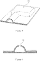
- FIG. 1-3 a device 2 comprised of a first and second sheet of rigid plastic 4, 6.
- Each sheet 4, 6 has a first major surface 8A and B and a second major surface 10 A and B and a thickness 12 A and B between the first and second major surfaces 8 and 10 A and B.
- the first sheet 4 has one or more flow channels 14 formed in it.
- the one or more flow channels 14 are formed in the sheet 4 in a manner such that the area of the sheet 4 where the flow channels 14 are formed extend away from the first major surface 8A of the sheet and beyond the normal plane of the second major surface 10A of the sheet.
- the first and second sheets 4, 6 are liquid tightly sealed to each other at their adjoining first major surfaces 8A and B. In this configuration the two sheets are sealed together such as by an adhesive or weld 16 although other methods such as heat bonds, sonic welding, solvent welding, clamps, nuts and bolts and the like can be used instead.
- One or more fittings 18 are secured in the flow channel(s) 14 at an edge of the two liquid tightly sealed sheets 4, 6 so as to function as a port for the system.
- a hose barb 30 can be used to secure the fitting to the tubing 24.
- an O-ring 19 is used to form a liquid tight seal around the outside of the fitting so that all liquid must pass through its bore 21. While shown with both sheets 4, 6 having a channel 14 as described below, one can use a similar device in the embodiment with only a channel 14 formed in one sheet 4 or 6 as described above in Figure 1 and 2 .
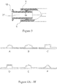
- Figure 4A-F shows various cross-sectional profiles of the flow channel of the device.
- the cross-sectional profile can be a semi circle or semi oval as shown in Figure 4 A and B respectively.
- it can be a triangle (4 F), a square or rectangle (4 C) or any half of a polygon having 5 or more sides.
- it can be a semi-polygon wherein the number of sides of the polygon p is greater than 4. Examples of these include a semi-hexagonal profile as shown in 4D and a semi-octagon in 4E.
- the device may have one or more chambers 20 also formed in the first layer that can act as mixing, filtration or storage containers.
- the device may have one or more holes 22 formed in the one or more flow channels 14 for the attachment of sensors such as those for of temperature, pressure, conductivity, flow and pH sensors or for filter capsules such as Opticap ® filters available from Millipore Corporation or for fittings such as hose barbs, Tri-Clover ® clamps and the like so that fluid in the system can be redirected to other devices or locations as needed.
- These holes 22 may be formed with internal screw threads, elastomer seals or other such devices for the liquid securing of the sensor, filter or fitting. If the sensors are disposable they can permanently secured by adhesives, solvent welds and the like.
- a plastic film or membrane may be sealed across the opening to form a sterile liquid tight barrier (not shown).
- FIGS 8 and 9 show a device in which each sheet has one or more flow paths 14 formed in them.
- both sheets have the one or more flow channels 14 formed in each sheet 4, 6 in a manner such that the area of the sheets 4 and 6 where the flow channels 14 are formed extend away from the first major surface 8 A or B of each sheet 4, 6 and beyond the normal plane of the second major surface 10A and B of each sheet 4, 6.
- the flow channel(s) 14 of each sheet 4, 6 are mirror images of the other so that when the sheets 4, 6 are joined the flow channel(s) 14 of each sheet 4, 6 are in alignment and register with each other.
- Figure 10A-F shows various cross-sectional profiles of the flow channel of the device.
- the cross-sectional profile of each sheet can be a semi circle or semi oval as shown in Figure 10 A and B respectively.
- it can be a triangle (10 F), a square or rectangle (10 C) or any half of a polygon having 5 or more sides.
- it can be a semi-polygon wherein the number of sides of the polygon p is greater than 4. Examples of these include a semi-hexagonal profile as shown in 10D and a semi-octagon in 10E. While the cross-sections of each sheet is shown as being identical to that of the other sheet and while this is the preferred method of doing so, the sheets could if desired have different cross-sectional profiles.
- Figure 11 shows the plastic sheets are formed as in Figures 1-3 with one sheet containing the flow channel(s) 14.
- a flexible tubing 24 such as a rubber or polyolefinic tube is inserted into the flow channel(s) 14 before the two sheets 4, 6 are attached to each other.
- Such tubes are well known in the industry and may be made of silicone, polyethylene, poly propylene, C-Flex ® polymer and the like. If desired the tubing may have reinforcement such as a braid of fiberglass or metal to add additional pressure resistance to it.
- Figure 12 shows the plastic sheets are formed as in Figures 8-9 with each sheet 4, 6 containing the flow channel(s) 14.
- a flexible tubing 24 such as a rubber or polyolefinic tube is inserted into the flow channel(s) 14 before the two sheets 4, 6 are attached to each other.
- Such tubes are well known in the industry and may be made of silicone, polyethylene, polypropylene, C-Flex ® polymer and the like. If desired the tubing may have reinforcement such as a braid of fiberglass or metal to add additional pressure resistance to it.
- Figure 13 shows an embodiment of the invention in which a fitting 18A in the tubing 24 is contained within the flow channel 14. If desired a hose barb 30 can be used to secure the fitting to the tubing 24. Alternatively, one can adhere, friction fit or melt bond the fitting 18A to the tubing 24. While shown with the embodiment in which both sheets 4, 6 have a channel 14, one can use a similar device in the embodiment with only a channel 14 formed in one sheet 4 or 6.
- the sheets can be made from a plastic selected from the group consisting of polyolefins, polycarbonates, epoxies, fiberglass reinforced thermosets, carbon reinforced thermosets, carbon composites, polysulphones and polyetherimides.
- the one or more flow channels can be formed in the rigid plastic sheet(s) in a variety of manners.
- it can be vacuum formed by preparing a pattern of the flow channel configuration on a mold, heating the plastic sheet until it is soft and then applying a vacuum to the plastic sheet so as to pull it against the pattern and form the channel configuration.
- the plastic may be formed by removing the plastic in the areas of the desired flow path such as by a router or a CNC milling machine, a laser or chemical etching.
- the plastic melt cast or solvent cast over a pattern containing the pattern of the flow channel configuration (either as a positive or a negative pattern) and it is allowed to cool or evaporate the solvent.
- thermosets a similar process may be used and the thermoset is allowed to cure or set against the pattern to form the device.
- the holes 22 may be formed as part of the process of making the sheets such as when the sheets are cast or they may be formed afterward such as by drilling or laser etching the hole in the desired location.
- the two sheets are aligned and securely held together in a liquid tight manner. This may be accomplished by adhesives. that hold the two sheets together or by solvents that selectively dissolve a portion of the adjoining plastic of each sheet and welds the two together as the solvent is evaporated. Heat sealing and heat or sonic or ultrasonic welding can also be used. Lasers and heat platens can be used for the beat welding. Aftematively, the two sheets can be secured by clamps around their edges. This may in some instances necessitate the use of a peripheral gasket. Likewise, a series of nuts and bolts or rivets, optionally with a peripheral gasket can be used to seal the sheets together,
- the fitting can be an elastomer material that is simply compressed and held in the flow channel as shown in Figure 3 .
- it may be retained simply by a friction fit between the inner diameter of the flow cennel and the outer diameter of the fitting.
- the use of adhesives, heat or sonic welding or solvent welding may also be used depending upon the material selected.
- the flow channel(s) 14 may be formed with a retention device such as an undercut 100. While shown as a rectangular undercut, it could be any other shape that retains the fitting.
- a device according to the present invention is made in the following manner.
- a lay out or design of the flow channel is charted and then a mold is formed such as by laying out metal or wood half round pieces.
- the pieces can be bent or cut to the particular configuration desired.
- the pieces are attached to a flat surface such as a vacuum board for a vacuform machine.
- the pieces can be treated with a release agent such as silicone or various machine, mineral or vegetable oils or waxes (natural or synthetic) to ensure the mold does not stick to the plastic sheet.
- a PTFE coating can be applied to the pieces.
- a piece of rigid plastic of a size to fit the board is then either simply placed over the board and pieces and then heated such as by a heat lamp or beat gun or the plastic sheet is heated until it is pliable first and then applied to the board.
- the plastic is clamped in place and a vacuum is drawn to pull the pliable plastic. against the mold.
- the plastic is cooled and released from the board,
- both sheets are to contain the channel(s) either a second sheet is simply made or if it is complicated a second mold which mirrors the first (ie is reciprocal to the first) is made and a second sheet is formed in a similar manner to the first,
- the same type of mold can be used with plastic that is formed from molten material which is poured over the mold or fiberglass or other composites by manufacturing the sheets over the mold(s) and using squeegees or rollers to ensure a good molded surface.
- Another method making a device is to simply rout out the channel(s) with a router device or CNC machine or laser or chemical etch as described above.
- the tubing is inserted between the sheets before they are secured together.
- the end fittings are secured between the sheets before or during when they are secured together.
- the fittings are attached to a supply of liquid and a means to hold the processed material such as a bag, tank, and the like.
- the liquid is run through the channel(s) and treated such as by a filter that is in line in the device.
Landscapes
- Chemical & Material Sciences (AREA)
- Engineering & Computer Science (AREA)
- General Engineering & Computer Science (AREA)
- Health & Medical Sciences (AREA)
- Mechanical Engineering (AREA)
- Chemical Kinetics & Catalysis (AREA)
- Clinical Laboratory Science (AREA)
- Hematology (AREA)
- General Health & Medical Sciences (AREA)
- Analytical Chemistry (AREA)
- Dispersion Chemistry (AREA)
- Organic Chemistry (AREA)
- Lining Or Joining Of Plastics Or The Like (AREA)
- Physical Or Chemical Processes And Apparatus (AREA)
- Rigid Pipes And Flexible Pipes (AREA)
- Valve Housings (AREA)
Description
- This invention relates to a rigid disposable flow path for disposable manufacturing such as in pharmaceutical, biopharmaceutical, nutriceutical, food or beverage processing and the like.
- Traditionally, fluid products such as biopharmaceuticals, food and beverages have been processed in stainless steel path ways. The steel piping and fluid path ways need to be cleaned such as with a hot caustic solution and then rinsed with several volumes of hot water and steam sterilized in between each use.
- One problem with such a system is making sure the system is properly cleaned and sterilized in between each use. Another issue is that the system is incapable of being flexible in size or configuration, limiting the user to a set volume and methodology dictated by the configuration.
- This has led to the recent adoption of plastic flexible containers and systems based on them. Most simply are plastic assemblies such as bags connected to each other by plastic tubing. One problem with such systems is that the system cannot be used at any high pressures due to the limitations of the plastic itself. A second issue is that it needs to be stabilized or retained to the surface on which it is used.
-
US2007/0278155 describes a medical fluid system with flexible disposable unit including flexible sheets sealed together to form at least one flow path.US 3,774,762 describes analogue fluid flow programming structures including a disposable component formed from layers of flexible plastic sheets sealed to each other according to a predetermined pattern.US 6,808,675 describes a freezing and thawing bag molded from plastic sheets with uniform thickness. Passageways may connect compartments of the bag. - One approach has been to use a clam shell or two piece manifold having a flow channel configuration or a relatively flat compressible surface between which the tubing of an assembly and/or the entire assembly can be held so that it can be kept in place and provided with some pressure resistance. See
WO 2009/017614 . - Another option is to use a flat or unconfigured bag and manifolds that contain the desired flow channels in the manifolds. The bag is placed between the manifolds and slightly constrained, The bag portions corresponding to those portions below the flow channels of the bag are then slightly inflated with a gas or liquid such that the bag portions fill the flow channels of the manifolds. The manifolds are then closed around the bag forming the desired flow path within the bag while in the manifolds. See
FR 0959435 filed January 23, 2009 - These devices have their limitations in terms of their complexity of operation and manufacture and their potential for leakage at pressure. For example, the use of separate components such as bags and tubes or an unconfigured bag and placing them in a manifold still limits one to the pressures at which the device may be run as the bag and often the tubes pressure resistance is only marginally improved by the use of the shell or manifolds. This is even more accentuated in the system using only a bag and forming the fluid pathways by inflating portions of the bag into the channels formed in the manifold inner surfaces. In this instance, the seal between the layers of the bag limits the amount of pressure that can be used. Additionally, when using individual components such as tubes connected to bags through a plastic port welded to the bag, one has to deal with obtaining and maintaining a good liquid tight seal between all the components. Most often a leak will occur where the tube is secured to the bag. The manifold devices do not stop such leaks from occurring and running the system at higher pressure and exacerbate the leak in some instances.
- The present invention provides a different device for forming a disposable pathway that is capable of holding and operating at high pressures and eliminating the leaks that may occur in other assemblies.
- The present invention is as defined in the claims and provides a disposable rigid flow path which by itself or in conjunction with a clam shell or manifold system provides additional pressure resistance for the disposable device.
- The device is comprised of a first sheet of rigid plastic material and a second sheet of plastic material, each sheet has a first major surface and a second major surface and a thickness between the first and second major surfaces at least one and preferably both sheets have one or more flow channels formed in them, the flow channels are formed in the sheet(s) in a manner such that the area of the sheet(s) where the one or more flow channels are formed extend away from the first major surface of the sheet(s) and beyond the normal plane of the second major surface of the sheet(s), the first and second sheets are liquid tightly sealed to each other at their adjoining first major surfaces, one or more flexible pieces of tubing are in the one or more flow channels between the two sheets and one or more fittings are secured in the one or more flexible pieces of tubing in the flow channels at an edge of the two liquid tightly sealed sheets so as to function as a port for the device.
- Each sheet may contain one or more flow channels and the flow channels of the two sheets may be aligned and in register with each other.
- The sheets may be made from a plastic selected from the group consisting of polyolefins, polycarbonates, epoxies, fiberglass reinforced thermosets, carbon reinforced thermosets, carbon composites, polysulphones and polyetherimides.
- The sheets may be liquid tightly sealed together by a means selected from the group consisting of heat bonds, ultra-sonic welding, vibration welding, heat-staking, solvent welding, adhesives, clamps, nuts and bolts and the like.
-
-
Figure 1 shows a device (not claimed) in cross-section view. -
Figure 2 shows the device ofFigure 1 in planar view. -
Figure 3 shows the device ofFigure 1 in a second cross-sectional view with a fitting attached. -
Figure 4 A-F shows some of the various cross-sectional profiles of the flow channels of the first device. -
Figure 5 shows a device in planar view. -
Figures 6 and7 show a sensor port of a device in cross-section view and planar views. -
Figure 8 shows a second device (not claimed). -
Figure 9 shows the device ofFigure 8 in planar view. -
Figure 10 A-F shows some of the various cross-sectional profiles of the flow channels of the second device. -
Figure 11 shows a cross sectional view of a device (not claimed). -
Figure 12 shows a cross sectional view of a a device (not claimed). -
Figure 13 shows a second cross-sectional view of an embodiment of the invention, showing a fitting attached. - In
Figures 1-3 is shown adevice 2 comprised of a first and second sheet ofrigid plastic sheet major surface 8A and B and a secondmajor surface 10 A and B and athickness 12 A and B between the first and secondmajor surfaces 8 and 10 A and B. In this device only thefirst sheet 4 has one ormore flow channels 14 formed in it. The one ormore flow channels 14 are formed in thesheet 4 in a manner such that the area of thesheet 4 where theflow channels 14 are formed extend away from the firstmajor surface 8A of the sheet and beyond the normal plane of the secondmajor surface 10A of the sheet. The first andsecond sheets major surfaces 8A and B. In this configuration the two sheets are sealed together such as by an adhesive orweld 16 although other methods such as heat bonds, sonic welding, solvent welding, clamps, nuts and bolts and the like can be used instead. - One or more fittings 18 (
Figure 3 ) are secured in the flow channel(s) 14 at an edge of the two liquid tightly sealedsheets hose barb 30 can be used to secure the fitting to thetubing 24. Alternatively, one can adhere, friction fit or melt bond the fitting 18A to thetubing 24. In this device an O-ring 19 is used to form a liquid tight seal around the outside of the fitting so that all liquid must pass through itsbore 21. While shown with bothsheets channel 14 as described below, one can use a similar device in the embodiment with only achannel 14 formed in onesheet Figure 1 and 2 . -
Figure 4A-F shows various cross-sectional profiles of the flow channel of the device. For example the cross-sectional profile can be a semi circle or semi oval as shown inFigure 4 A and B respectively. Alternatively it can be a triangle (4 F), a square or rectangle (4 C) or any half of a polygon having 5 or more sides. Put another way it can be a semi-polygon wherein the number of sides of the polygon p is greater than 4. Examples of these include a semi-hexagonal profile as shown in 4D and a semi-octagon in 4E. - Optionally, as shown in
Figure 5 the device may have one ormore chambers 20 also formed in the first layer that can act as mixing, filtration or storage containers. Additionally, as shown inFigures 6 and7 the device may have one or more holes 22 formed in the one ormore flow channels 14 for the attachment of sensors such as those for of temperature, pressure, conductivity, flow and pH sensors or for filter capsules such as Opticap® filters available from Millipore Corporation or for fittings such as hose barbs, Tri-Clover® clamps and the like so that fluid in the system can be redirected to other devices or locations as needed. These holes 22 may be formed with internal screw threads, elastomer seals or other such devices for the liquid securing of the sensor, filter or fitting. If the sensors are disposable they can permanently secured by adhesives, solvent welds and the like. Optionally, for those sensors that do not need to contact the fluid directly a plastic film or membrane may be sealed across the opening to form a sterile liquid tight barrier (not shown). -
Figures 8 and9 show a device in which each sheet has one ormore flow paths 14 formed in them. In this instance both sheets have the one ormore flow channels 14 formed in eachsheet sheets flow channels 14 are formed extend away from the firstmajor surface 8 A or B of eachsheet major surface 10A and B of eachsheet sheet sheets sheet -
Figure 10A-F shows various cross-sectional profiles of the flow channel of the device. For example the cross-sectional profile of each sheet can be a semi circle or semi oval as shown inFigure 10 A and B respectively. Alternatively it can be a triangle (10 F), a square or rectangle (10 C) or any half of a polygon having 5 or more sides. Put another way it can be a semi-polygon wherein the number of sides of the polygon p is greater than 4. Examples of these include a semi-hexagonal profile as shown in 10D and a semi-octagon in 10E. While the cross-sections of each sheet is shown as being identical to that of the other sheet and while this is the preferred method of doing so, the sheets could if desired have different cross-sectional profiles. -
Figure 11 shows the plastic sheets are formed as inFigures 1-3 with one sheet containing the flow channel(s) 14. Aflexible tubing 24 such as a rubber or polyolefinic tube is inserted into the flow channel(s) 14 before the twosheets -
Figure 12 shows the plastic sheets are formed as inFigures 8-9 with eachsheet flexible tubing 24 such as a rubber or polyolefinic tube is inserted into the flow channel(s) 14 before the twosheets -
Figure 13 shows an embodiment of the invention in which a fitting 18A in thetubing 24 is contained within theflow channel 14. If desired ahose barb 30 can be used to secure the fitting to thetubing 24. Alternatively, one can adhere, friction fit or melt bond the fitting 18A to thetubing 24. While shown with the embodiment in which bothsheets channel 14, one can use a similar device in the embodiment with only achannel 14 formed in onesheet - The sheets can be made from a plastic selected from the group consisting of polyolefins, polycarbonates, epoxies, fiberglass reinforced thermosets, carbon reinforced thermosets, carbon composites, polysulphones and polyetherimides.
- The one or more flow channels can be formed in the rigid plastic sheet(s) in a variety of manners. For example it can be vacuum formed by preparing a pattern of the flow channel configuration on a mold, heating the plastic sheet until it is soft and then applying a vacuum to the plastic sheet so as to pull it against the pattern and form the channel configuration. Alternatively, if the plastic is thick enough it may be formed by removing the plastic in the areas of the desired flow path such as by a router or a CNC milling machine, a laser or chemical etching. Alternatively, the plastic melt cast or solvent cast over a pattern containing the pattern of the flow channel configuration (either as a positive or a negative pattern) and it is allowed to cool or evaporate the solvent. For thermosets, a similar process may be used and the thermoset is allowed to cure or set against the pattern to form the device.
- The holes 22 may be formed as part of the process of making the sheets such as when the sheets are cast or they may be formed afterward such as by drilling or laser etching the hole in the desired location.
- Once formed, the two sheets are aligned and securely held together in a liquid tight manner. This may be accomplished by adhesives. that hold the two sheets together or by solvents that selectively dissolve a portion of the adjoining plastic of each sheet and welds the two together as the solvent is evaporated. Heat sealing and heat or sonic or ultrasonic welding can also be used. Lasers and heat platens can be used for the beat welding. Aftematively, the two sheets can be secured by clamps around their edges. This may in some instances necessitate the use of a peripheral gasket. Likewise, a series of nuts and bolts or rivets, optionally with a peripheral gasket can be used to seal the sheets together,
- At the edge of the sheets where the flow channel exits or enter the sheets, one can mount a fitting to the opening to allow for the attachment of tubing, filters, and other such ancillary equipment. In many instances the fitting can be an elastomer material that is simply compressed and held in the flow channel as shown in
Figure 3 . Optionally, it may be retained simply by a friction fit between the inner diameter of the flow cennel and the outer diameter of the fitting. The use of adhesives, heat or sonic welding or solvent welding may also be used depending upon the material selected. As shown inFigure 13 , the flow channel(s) 14 may be formed with a retention device such as an undercut 100. While shown as a rectangular undercut, it could be any other shape that retains the fitting. - A device according to the present invention is made in the following manner. A lay out or design of the flow channel is charted and then a mold is formed such as by laying out metal or wood half round pieces. The pieces can be bent or cut to the particular configuration desired. The pieces are attached to a flat surface such as a vacuum board for a vacuform machine. If desired or required, the pieces can be treated with a release agent such as silicone or various machine, mineral or vegetable oils or waxes (natural or synthetic) to ensure the mold does not stick to the plastic sheet. Alternatively a PTFE coating can be applied to the pieces.
- A piece of rigid plastic of a size to fit the board is then either simply placed over the board and pieces and then heated such as by a heat lamp or beat gun or the plastic sheet is heated until it is pliable first and then applied to the board. The plastic is clamped in place and a vacuum is drawn to pull the pliable plastic. against the mold. The plastic is cooled and released from the board,
- If only one sheet is to contain the channel(s), it then secured to a flat sheet of plastic such that the channel(s) is formed at the interface between the faces of the two sheets.
- If both sheets are to contain the channel(s) either a second sheet is simply made or if it is complicated a second mold which mirrors the first (ie is reciprocal to the first) is made and a second sheet is formed in a similar manner to the first,
- The same type of mold can be used with plastic that is formed from molten material which is poured over the mold or fiberglass or other composites by manufacturing the sheets over the mold(s) and using squeegees or rollers to ensure a good molded surface.
- Another method making a device is to simply rout out the channel(s) with a router device or CNC machine or laser or chemical etch as described above.
- The tubing is inserted between the sheets before they are secured together. In devices where no separate tubing is used, the end fittings are secured between the sheets before or during when they are secured together. In the case of no separate tubing being in the channel(s), one may want to wash or flush the channel(s) before use to remove any release agent that may be left. Alternatively, this can be done as each sheet is made.
- Once the sheets have been made and secured to each other, the fittings are attached to a supply of liquid and a means to hold the processed material such as a bag, tank, and the like. The liquid is run through the channel(s) and treated such as by a filter that is in line in the device.
Claims (7)
- A device comprising a first sheet of rigid plastic material (4) and a second sheet of plastic material (6), each sheet has a first major surface (8A, 8B) and a second major surface and a thickness (12A, 12B) between the first and second major surfaces, at least one of the first and second sheets has one or more flow channels (14) formed therein, the one or more flow channels are formed in the at least one sheet in manner such that the area of the sheet where the flow channels are formed extend away from the first major surface of the sheet and beyond the normal plane of the second major surface of the sheet, and the first and second sheets are liquid tightly sealed to each other at their adjoining first major surfaces and further comprising one or more flexible pieces of tubing (24) contained in the one or more flow channels between the two sheets and one or more fittings (18A) secured in the one or more flexible pieces of tubing (24) in the one or more flow channels at an edge of the two liquid tightly sealed sheets.
- The device of claim 1 wherein the first and second sheets have one or more flow channels (14) in them.
- The device of claim 1 wherein the first and second sheets have one or more flow channels (14) in them and the flow channels of the two sheets are aligned and in register with each other.
- The device of claim 1 wherein the sheets are made from a plastic selected from the group consisting of polyolefins, polycarbonates, epoxies, fiberglass reinforced thermosets, carbon reinforced thermosets, carbon composites, polysulphones and polyetherimides.
- The device of claim 1 wherein the sheets are liquid tightly sealed together by a means selected from the group consisting of heat bonds, ultra-sonic welding, vibration welding, heat-staking, solvent welding, adhesives, clamps and nuts and bolts.
- The apparatus of any one of clams 1 to 5 wherein a hose barb (30) is used to secure the fitting (18A) to the flexible tubing (24).
- The device of any one of claims 1 to 6 wherein the flexible tubing (24) has reinforcement such as a braid of fiberglass or metal to add additional pressure resistance to it.
Applications Claiming Priority (2)
| Application Number | Priority Date | Filing Date | Title |
|---|---|---|---|
| US36064410P | 2010-07-01 | 2010-07-01 | |
| PCT/US2011/042188 WO2012003185A1 (en) | 2010-07-01 | 2011-06-28 | Rigid disposable flow path |
Publications (3)
| Publication Number | Publication Date |
|---|---|
| EP2588789A1 EP2588789A1 (en) | 2013-05-08 |
| EP2588789A4 EP2588789A4 (en) | 2014-06-18 |
| EP2588789B1 true EP2588789B1 (en) | 2022-06-08 |
Family
ID=45398783
Family Applications (1)
| Application Number | Title | Priority Date | Filing Date |
|---|---|---|---|
| EP11801350.7A Active EP2588789B1 (en) | 2010-07-01 | 2011-06-28 | Rigid disposable flow path |
Country Status (7)
| Country | Link |
|---|---|
| US (3) | US20120000566A1 (en) |
| EP (1) | EP2588789B1 (en) |
| JP (1) | JP5837928B2 (en) |
| KR (1) | KR20130030315A (en) |
| CN (1) | CN102971565B (en) |
| SG (2) | SG185461A1 (en) |
| WO (1) | WO2012003185A1 (en) |
Families Citing this family (11)
| Publication number | Priority date | Publication date | Assignee | Title |
|---|---|---|---|---|
| US8640556B2 (en) | 2010-12-03 | 2014-02-04 | Alfa Wassermann | Automated aseptic sampling workstation and sample collection devices therefore |
| KR20130030315A (en) * | 2010-07-01 | 2013-03-26 | 이엠디 밀리포어 코포레이션 | Rigid disposable flow path |
| US8815179B2 (en) | 2010-12-03 | 2014-08-26 | Alfa Wassermann, Inc. | Automated aseptic liquid collection workstations and collection devices therefore |
| JP6960079B2 (en) * | 2015-04-21 | 2021-11-05 | キョーラク株式会社 | panel |
| AU2017299804B2 (en) | 2016-07-22 | 2019-10-31 | Alfa Wassermann, Inc. | Fluid handling systems and method for ultracentrifuges |
| US10591091B1 (en) * | 2016-11-22 | 2020-03-17 | Southwest Greene International, Inc. | Laminated U-shaped channel |
| WO2018203385A1 (en) * | 2017-05-02 | 2018-11-08 | 三菱電機株式会社 | Exhaust gas recirculation valve and method for manufacturing exhaust gas recirculation valve |
| DE102017207513A1 (en) * | 2017-05-04 | 2018-11-08 | Hamm Ag | Fastening device for hoses |
| JP7446731B2 (en) * | 2018-08-24 | 2024-03-11 | キヤノン株式会社 | Structure having a flow path and method for manufacturing the same |
| WO2020039860A1 (en) * | 2018-08-24 | 2020-02-27 | キヤノン株式会社 | Structure having flow channel, and method for manufacturing same |
| KR102522521B1 (en) * | 2021-01-05 | 2023-04-18 | 순천향대학교 산학협력단 | ROS-responsive drug delivery nanoparticles produced by a device for producing nanoparticles |
Citations (1)
| Publication number | Priority date | Publication date | Assignee | Title |
|---|---|---|---|---|
| US20070235673A1 (en) * | 2006-04-11 | 2007-10-11 | Welch Allyn, Inc. | Microfluidic device with elastomeric seal |
Family Cites Families (43)
| Publication number | Priority date | Publication date | Assignee | Title |
|---|---|---|---|---|
| US1608905A (en) | 1924-06-18 | 1926-11-30 | Joseph B Murray | Heat-conducting tube and method of making the same |
| US1649752A (en) * | 1925-02-13 | 1927-11-15 | Albert Pearson | Pipe sleeve |
| US2624366A (en) * | 1952-07-22 | 1953-01-06 | William J Pugh | Plural hose |
| US3086559A (en) | 1959-02-19 | 1963-04-23 | Leland H Grenell | Roll bonded tubing fittings |
| US3485245A (en) * | 1967-06-21 | 1969-12-23 | Ibm | Portable fluid heater |
| US3774762A (en) | 1971-01-20 | 1973-11-27 | E Lichtenstein | Analogue fluid flow programming structures |
| US3996968A (en) * | 1973-01-23 | 1976-12-14 | E. I. Du Pont De Nemours And Company | Tubing articles |
| JPS5341780Y2 (en) * | 1974-03-29 | 1978-10-07 | ||
| JPS5237616U (en) * | 1976-08-04 | 1977-03-17 | ||
| JPS5341780U (en) * | 1976-09-14 | 1978-04-11 | ||
| JPS5429409U (en) * | 1977-08-01 | 1979-02-26 | ||
| US4297891A (en) * | 1980-01-11 | 1981-11-03 | Halliburton Services | Apparatus and method for protecting a transducer |
| DE3220023C2 (en) | 1982-05-27 | 1993-05-27 | Cellofoam Deutschland Gmbh, 7950 Biberach | Sound-absorbing flow channel and method for its manufacture |
| JPS58196489U (en) * | 1982-06-25 | 1983-12-27 | キヨ−ラク株式会社 | plastic bulkhead duct |
| JPS6042115A (en) | 1983-08-17 | 1985-03-06 | Takagi Kagaku Kenkyusho:Kk | Air conditioner of vehicle seat |
| IT1179369B (en) | 1984-05-15 | 1987-09-16 | Ital Idee Srl | MULTIPLE FILTER GROUP, ESPECIALLY FOR VENTILATION AND AIR CONDITIONING SYSTEMS FOR MOTOR VEHICLES AND CLOSED ENVIRONMENTS, EQUIPPED WITH MEANS OF CONTROL OF EFFICIENCY |
| JPS63285930A (en) * | 1987-05-18 | 1988-11-22 | Sanyo Electric Co Ltd | Formation of hyperfine tube |
| JPS63313028A (en) * | 1987-06-16 | 1988-12-21 | Fujikura Ltd | Pressure sensor buried pipe |
| GB8815977D0 (en) * | 1988-07-05 | 1988-08-10 | British Telecomm | Transmission line ducts |
| JP3118579B2 (en) * | 1992-12-09 | 2000-12-18 | 金尾 茂樹 | Pressure-resistant synthetic resin tube |
| KR100217515B1 (en) | 1994-09-30 | 1999-09-01 | 오타 유다카 | Laminated heat exchanger tube and manufactuing method therefor |
| US6808675B1 (en) * | 1996-06-25 | 2004-10-26 | Thermogenesis Corp. | Freezing and thawing bag, mold, apparatus and method |
| US6146124A (en) * | 1996-06-25 | 2000-11-14 | Thermogenesis Corp. | Freezing and thawing bag, mold, apparatus and method |
| US6041829A (en) * | 1996-11-21 | 2000-03-28 | Nate International | Undersea pipe |
| JPH10169868A (en) * | 1996-12-04 | 1998-06-26 | Sekisui Chem Co Ltd | Pipe fittings |
| WO1999060397A1 (en) * | 1998-05-18 | 1999-11-25 | University Of Washington | Liquid analysis cartridge |
| US6471855B1 (en) * | 2000-11-22 | 2002-10-29 | Baxter International Inc. | Cassette with integral separation device |
| DE10215347A1 (en) | 2001-04-10 | 2002-12-12 | Denso Corp | Vehicle air conditioning duct structure, method of manufacturing the same, and electrical wiring structure |
| FR2831216B1 (en) * | 2001-10-24 | 2004-01-16 | Wecosta | THERMOFORMED INTAKE DUCT IN NON-WOVEN MATERIAL WITH DOUBLE BENDS |
| US20050082826A1 (en) * | 2003-10-17 | 2005-04-21 | Twin Bay Medical, Inc. | Barb clamp |
| US8038639B2 (en) * | 2004-11-04 | 2011-10-18 | Baxter International Inc. | Medical fluid system with flexible sheeting disposable unit |
| DE102005000799A1 (en) | 2005-01-05 | 2006-07-13 | Roche Diagnostics Gmbh | Fluidic structure and method for creating a fluidic structure |
| JP2007132579A (en) * | 2005-11-09 | 2007-05-31 | Max Co Ltd | Pipe conduit structure, hot water supply system and room |
| JP2007231136A (en) | 2006-02-28 | 2007-09-13 | Kyoraku Co Ltd | Blow molded panel composed of propylene-based resin composition, blow molded panel composed of the composition and deck board for automobile composed of the blow molded panel |
| US20090182275A1 (en) * | 2006-12-06 | 2009-07-16 | Huddleston Herbert D | Disposable shutoff valve apparatus for suction devices and the like |
| FR2911907B1 (en) * | 2007-01-26 | 2009-03-06 | Technip France Sa | FLEXIBLE UPLINK CONDUIT FOR TRANSPORTING HYDROCARBONS. |
| EP2173449A1 (en) | 2007-08-02 | 2010-04-14 | Millipore Corporation | System and apparatus for processing fluid samples |
| EP2082920B1 (en) | 2008-01-24 | 2012-04-11 | Eberspächer catem GmbH & Co. KG | Electric additional heating for a motor vehicle |
| JP2009204144A (en) * | 2008-02-29 | 2009-09-10 | Bridgestone Corp | Connection method of hose and resin nipple for mouthpiece and hose mouthpiece connection structure |
| US8877648B2 (en) * | 2009-03-26 | 2014-11-04 | Semprius, Inc. | Methods of forming printable integrated circuit devices by selective etching to suspend the devices from a handling substrate and devices formed thereby |
| KR101509786B1 (en) | 2009-09-28 | 2015-04-06 | 현대자동차주식회사 | Sensor port inserted silicon hose and method for manufacturing the same |
| FR2954367B1 (en) | 2009-12-22 | 2014-09-19 | Eurovia | TRANSFERABLE CONCRETE BLOCK |
| KR20130030315A (en) * | 2010-07-01 | 2013-03-26 | 이엠디 밀리포어 코포레이션 | Rigid disposable flow path |
-
2011
- 2011-06-28 KR KR1020127033386A patent/KR20130030315A/en not_active Ceased
- 2011-06-28 US US13/170,926 patent/US20120000566A1/en not_active Abandoned
- 2011-06-28 WO PCT/US2011/042188 patent/WO2012003185A1/en not_active Ceased
- 2011-06-28 CN CN201180032766.2A patent/CN102971565B/en active Active
- 2011-06-28 JP JP2013518577A patent/JP5837928B2/en active Active
- 2011-06-28 EP EP11801350.7A patent/EP2588789B1/en active Active
- 2011-06-28 SG SG2012082160A patent/SG185461A1/en unknown
- 2011-06-28 SG SG10201505992UA patent/SG10201505992UA/en unknown
-
2013
- 2013-11-08 US US14/074,815 patent/US9494259B2/en active Active
-
2014
- 2014-01-13 US US14/153,114 patent/US20140124083A1/en not_active Abandoned
Patent Citations (1)
| Publication number | Priority date | Publication date | Assignee | Title |
|---|---|---|---|---|
| US20070235673A1 (en) * | 2006-04-11 | 2007-10-11 | Welch Allyn, Inc. | Microfluidic device with elastomeric seal |
Also Published As
| Publication number | Publication date |
|---|---|
| WO2012003185A1 (en) | 2012-01-05 |
| US20140090738A1 (en) | 2014-04-03 |
| US20140124083A1 (en) | 2014-05-08 |
| CN102971565A (en) | 2013-03-13 |
| KR20130030315A (en) | 2013-03-26 |
| JP2013534598A (en) | 2013-09-05 |
| EP2588789A4 (en) | 2014-06-18 |
| SG10201505992UA (en) | 2015-09-29 |
| JP5837928B2 (en) | 2015-12-24 |
| EP2588789A1 (en) | 2013-05-08 |
| CN102971565B (en) | 2016-06-01 |
| SG185461A1 (en) | 2012-12-28 |
| US20120000566A1 (en) | 2012-01-05 |
| US9494259B2 (en) | 2016-11-15 |
Similar Documents
| Publication | Publication Date | Title |
|---|---|---|
| US9494259B2 (en) | Rigid disposable flow path | |
| JP6224692B2 (en) | Aseptic connector and sterilization circuit | |
| EP3078735B1 (en) | Single-use container, system and method for the prevention of over-pressurization | |
| WO2006050105A1 (en) | Multi-compartment pouch having a frangible seal | |
| JP5260622B2 (en) | Deaerator | |
| US8870230B2 (en) | Single use wall pass-through system | |
| US11173635B2 (en) | Fluid transfer assembly, a fluid transfer system, and a related method | |
| JP4885050B2 (en) | Deaerator | |
| JP2010264405A (en) | Deaerator | |
| US11794425B2 (en) | Resin barrier device, gasket and method for infusing a preform | |
| US12280234B2 (en) | Integrated aseptic system and method of making the same | |
| EP3446861A1 (en) | Method for sealing medical devices | |
| KR20200099164A (en) | Improved filter unit for whole blood and blood derivatives | |
| JPH11268131A (en) | Cylindrical film joined body by annular fusion and deaerator using the joined body |
Legal Events
| Date | Code | Title | Description |
|---|---|---|---|
| PUAI | Public reference made under article 153(3) epc to a published international application that has entered the european phase |
Free format text: ORIGINAL CODE: 0009012 |
|
| 17P | Request for examination filed |
Effective date: 20121120 |
|
| AK | Designated contracting states |
Kind code of ref document: A1 Designated state(s): AL AT BE BG CH CY CZ DE DK EE ES FI FR GB GR HR HU IE IS IT LI LT LU LV MC MK MT NL NO PL PT RO RS SE SI SK SM TR |
|
| DAX | Request for extension of the european patent (deleted) | ||
| A4 | Supplementary search report drawn up and despatched |
Effective date: 20140519 |
|
| RIC1 | Information provided on ipc code assigned before grant |
Ipc: B01L 3/00 20060101ALI20140513BHEP Ipc: F16L 9/22 20060101ALI20140513BHEP Ipc: F16L 3/12 20060101AFI20140513BHEP Ipc: F16L 9/127 20060101ALI20140513BHEP Ipc: F16L 9/133 20060101ALI20140513BHEP Ipc: B01J 19/00 20060101ALI20140513BHEP |
|
| RAP1 | Party data changed (applicant data changed or rights of an application transferred) |
Owner name: EMD MILLIPORE CORPORATION |
|
| STAA | Information on the status of an ep patent application or granted ep patent |
Free format text: STATUS: EXAMINATION IS IN PROGRESS |
|
| 17Q | First examination report despatched |
Effective date: 20181001 |
|
| GRAP | Despatch of communication of intention to grant a patent |
Free format text: ORIGINAL CODE: EPIDOSNIGR1 |
|
| STAA | Information on the status of an ep patent application or granted ep patent |
Free format text: STATUS: GRANT OF PATENT IS INTENDED |
|
| INTG | Intention to grant announced |
Effective date: 20220119 |
|
| GRAS | Grant fee paid |
Free format text: ORIGINAL CODE: EPIDOSNIGR3 |
|
| GRAA | (expected) grant |
Free format text: ORIGINAL CODE: 0009210 |
|
| STAA | Information on the status of an ep patent application or granted ep patent |
Free format text: STATUS: THE PATENT HAS BEEN GRANTED |
|
| AK | Designated contracting states |
Kind code of ref document: B1 Designated state(s): AL AT BE BG CH CY CZ DE DK EE ES FI FR GB GR HR HU IE IS IT LI LT LU LV MC MK MT NL NO PL PT RO RS SE SI SK SM TR |
|
| REG | Reference to a national code |
Ref country code: GB Ref legal event code: FG4D |
|
| REG | Reference to a national code |
Ref country code: AT Ref legal event code: REF Ref document number: 1497153 Country of ref document: AT Kind code of ref document: T Effective date: 20220615 Ref country code: CH Ref legal event code: EP |
|
| REG | Reference to a national code |
Ref country code: DE Ref legal event code: R096 Ref document number: 602011072981 Country of ref document: DE |
|
| REG | Reference to a national code |
Ref country code: IE Ref legal event code: FG4D |
|
| REG | Reference to a national code |
Ref country code: LT Ref legal event code: MG9D |
|
| REG | Reference to a national code |
Ref country code: NL Ref legal event code: MP Effective date: 20220608 |
|
| PG25 | Lapsed in a contracting state [announced via postgrant information from national office to epo] |
Ref country code: SE Free format text: LAPSE BECAUSE OF FAILURE TO SUBMIT A TRANSLATION OF THE DESCRIPTION OR TO PAY THE FEE WITHIN THE PRESCRIBED TIME-LIMIT Effective date: 20220608 Ref country code: NO Free format text: LAPSE BECAUSE OF FAILURE TO SUBMIT A TRANSLATION OF THE DESCRIPTION OR TO PAY THE FEE WITHIN THE PRESCRIBED TIME-LIMIT Effective date: 20220908 Ref country code: LT Free format text: LAPSE BECAUSE OF FAILURE TO SUBMIT A TRANSLATION OF THE DESCRIPTION OR TO PAY THE FEE WITHIN THE PRESCRIBED TIME-LIMIT Effective date: 20220608 Ref country code: HR Free format text: LAPSE BECAUSE OF FAILURE TO SUBMIT A TRANSLATION OF THE DESCRIPTION OR TO PAY THE FEE WITHIN THE PRESCRIBED TIME-LIMIT Effective date: 20220608 Ref country code: GR Free format text: LAPSE BECAUSE OF FAILURE TO SUBMIT A TRANSLATION OF THE DESCRIPTION OR TO PAY THE FEE WITHIN THE PRESCRIBED TIME-LIMIT Effective date: 20220909 Ref country code: FI Free format text: LAPSE BECAUSE OF FAILURE TO SUBMIT A TRANSLATION OF THE DESCRIPTION OR TO PAY THE FEE WITHIN THE PRESCRIBED TIME-LIMIT Effective date: 20220608 Ref country code: ES Free format text: LAPSE BECAUSE OF FAILURE TO SUBMIT A TRANSLATION OF THE DESCRIPTION OR TO PAY THE FEE WITHIN THE PRESCRIBED TIME-LIMIT Effective date: 20220608 Ref country code: BG Free format text: LAPSE BECAUSE OF FAILURE TO SUBMIT A TRANSLATION OF THE DESCRIPTION OR TO PAY THE FEE WITHIN THE PRESCRIBED TIME-LIMIT Effective date: 20220908 |
|
| REG | Reference to a national code |
Ref country code: AT Ref legal event code: MK05 Ref document number: 1497153 Country of ref document: AT Kind code of ref document: T Effective date: 20220608 |
|
| PG25 | Lapsed in a contracting state [announced via postgrant information from national office to epo] |
Ref country code: RS Free format text: LAPSE BECAUSE OF FAILURE TO SUBMIT A TRANSLATION OF THE DESCRIPTION OR TO PAY THE FEE WITHIN THE PRESCRIBED TIME-LIMIT Effective date: 20220608 Ref country code: LV Free format text: LAPSE BECAUSE OF FAILURE TO SUBMIT A TRANSLATION OF THE DESCRIPTION OR TO PAY THE FEE WITHIN THE PRESCRIBED TIME-LIMIT Effective date: 20220608 |
|
| PG25 | Lapsed in a contracting state [announced via postgrant information from national office to epo] |
Ref country code: NL Free format text: LAPSE BECAUSE OF FAILURE TO SUBMIT A TRANSLATION OF THE DESCRIPTION OR TO PAY THE FEE WITHIN THE PRESCRIBED TIME-LIMIT Effective date: 20220608 |
|
| PG25 | Lapsed in a contracting state [announced via postgrant information from national office to epo] |
Ref country code: SM Free format text: LAPSE BECAUSE OF FAILURE TO SUBMIT A TRANSLATION OF THE DESCRIPTION OR TO PAY THE FEE WITHIN THE PRESCRIBED TIME-LIMIT Effective date: 20220608 Ref country code: SK Free format text: LAPSE BECAUSE OF FAILURE TO SUBMIT A TRANSLATION OF THE DESCRIPTION OR TO PAY THE FEE WITHIN THE PRESCRIBED TIME-LIMIT Effective date: 20220608 Ref country code: RO Free format text: LAPSE BECAUSE OF FAILURE TO SUBMIT A TRANSLATION OF THE DESCRIPTION OR TO PAY THE FEE WITHIN THE PRESCRIBED TIME-LIMIT Effective date: 20220608 Ref country code: PT Free format text: LAPSE BECAUSE OF FAILURE TO SUBMIT A TRANSLATION OF THE DESCRIPTION OR TO PAY THE FEE WITHIN THE PRESCRIBED TIME-LIMIT Effective date: 20221010 Ref country code: EE Free format text: LAPSE BECAUSE OF FAILURE TO SUBMIT A TRANSLATION OF THE DESCRIPTION OR TO PAY THE FEE WITHIN THE PRESCRIBED TIME-LIMIT Effective date: 20220608 Ref country code: CZ Free format text: LAPSE BECAUSE OF FAILURE TO SUBMIT A TRANSLATION OF THE DESCRIPTION OR TO PAY THE FEE WITHIN THE PRESCRIBED TIME-LIMIT Effective date: 20220608 Ref country code: AT Free format text: LAPSE BECAUSE OF FAILURE TO SUBMIT A TRANSLATION OF THE DESCRIPTION OR TO PAY THE FEE WITHIN THE PRESCRIBED TIME-LIMIT Effective date: 20220608 |
|
| REG | Reference to a national code |
Ref country code: BE Ref legal event code: MM Effective date: 20220630 |
|
| PG25 | Lapsed in a contracting state [announced via postgrant information from national office to epo] |
Ref country code: PL Free format text: LAPSE BECAUSE OF FAILURE TO SUBMIT A TRANSLATION OF THE DESCRIPTION OR TO PAY THE FEE WITHIN THE PRESCRIBED TIME-LIMIT Effective date: 20220608 Ref country code: IS Free format text: LAPSE BECAUSE OF FAILURE TO SUBMIT A TRANSLATION OF THE DESCRIPTION OR TO PAY THE FEE WITHIN THE PRESCRIBED TIME-LIMIT Effective date: 20221008 |
|
| REG | Reference to a national code |
Ref country code: DE Ref legal event code: R097 Ref document number: 602011072981 Country of ref document: DE |
|
| PG25 | Lapsed in a contracting state [announced via postgrant information from national office to epo] |
Ref country code: MC Free format text: LAPSE BECAUSE OF FAILURE TO SUBMIT A TRANSLATION OF THE DESCRIPTION OR TO PAY THE FEE WITHIN THE PRESCRIBED TIME-LIMIT Effective date: 20220608 Ref country code: AL Free format text: LAPSE BECAUSE OF FAILURE TO SUBMIT A TRANSLATION OF THE DESCRIPTION OR TO PAY THE FEE WITHIN THE PRESCRIBED TIME-LIMIT Effective date: 20220608 |
|
| PLBE | No opposition filed within time limit |
Free format text: ORIGINAL CODE: 0009261 |
|
| STAA | Information on the status of an ep patent application or granted ep patent |
Free format text: STATUS: NO OPPOSITION FILED WITHIN TIME LIMIT |
|
| PG25 | Lapsed in a contracting state [announced via postgrant information from national office to epo] |
Ref country code: LU Free format text: LAPSE BECAUSE OF NON-PAYMENT OF DUE FEES Effective date: 20220628 Ref country code: IE Free format text: LAPSE BECAUSE OF NON-PAYMENT OF DUE FEES Effective date: 20220628 Ref country code: DK Free format text: LAPSE BECAUSE OF FAILURE TO SUBMIT A TRANSLATION OF THE DESCRIPTION OR TO PAY THE FEE WITHIN THE PRESCRIBED TIME-LIMIT Effective date: 20220608 |
|
| 26N | No opposition filed |
Effective date: 20230310 |
|
| GBPC | Gb: european patent ceased through non-payment of renewal fee |
Effective date: 20220908 |
|
| PG25 | Lapsed in a contracting state [announced via postgrant information from national office to epo] |
Ref country code: SI Free format text: LAPSE BECAUSE OF FAILURE TO SUBMIT A TRANSLATION OF THE DESCRIPTION OR TO PAY THE FEE WITHIN THE PRESCRIBED TIME-LIMIT Effective date: 20220608 Ref country code: BE Free format text: LAPSE BECAUSE OF NON-PAYMENT OF DUE FEES Effective date: 20220630 |
|
| P01 | Opt-out of the competence of the unified patent court (upc) registered |
Effective date: 20230602 |
|
| PG25 | Lapsed in a contracting state [announced via postgrant information from national office to epo] |
Ref country code: GB Free format text: LAPSE BECAUSE OF NON-PAYMENT OF DUE FEES Effective date: 20220908 |
|
| PG25 | Lapsed in a contracting state [announced via postgrant information from national office to epo] |
Ref country code: IT Free format text: LAPSE BECAUSE OF FAILURE TO SUBMIT A TRANSLATION OF THE DESCRIPTION OR TO PAY THE FEE WITHIN THE PRESCRIBED TIME-LIMIT Effective date: 20220608 |
|
| PG25 | Lapsed in a contracting state [announced via postgrant information from national office to epo] |
Ref country code: HU Free format text: LAPSE BECAUSE OF FAILURE TO SUBMIT A TRANSLATION OF THE DESCRIPTION OR TO PAY THE FEE WITHIN THE PRESCRIBED TIME-LIMIT; INVALID AB INITIO Effective date: 20110628 |
|
| PG25 | Lapsed in a contracting state [announced via postgrant information from national office to epo] |
Ref country code: MK Free format text: LAPSE BECAUSE OF FAILURE TO SUBMIT A TRANSLATION OF THE DESCRIPTION OR TO PAY THE FEE WITHIN THE PRESCRIBED TIME-LIMIT Effective date: 20220608 Ref country code: CY Free format text: LAPSE BECAUSE OF FAILURE TO SUBMIT A TRANSLATION OF THE DESCRIPTION OR TO PAY THE FEE WITHIN THE PRESCRIBED TIME-LIMIT Effective date: 20220608 |
|
| PGFP | Annual fee paid to national office [announced via postgrant information from national office to epo] |
Ref country code: DE Payment date: 20240502 Year of fee payment: 14 |
|
| PGFP | Annual fee paid to national office [announced via postgrant information from national office to epo] |
Ref country code: FR Payment date: 20240509 Year of fee payment: 14 |
|
| PG25 | Lapsed in a contracting state [announced via postgrant information from national office to epo] |
Ref country code: MT Free format text: LAPSE BECAUSE OF FAILURE TO SUBMIT A TRANSLATION OF THE DESCRIPTION OR TO PAY THE FEE WITHIN THE PRESCRIBED TIME-LIMIT Effective date: 20220608 |
|
| PGFP | Annual fee paid to national office [announced via postgrant information from national office to epo] |
Ref country code: CH Payment date: 20240704 Year of fee payment: 14 |
|
| PG25 | Lapsed in a contracting state [announced via postgrant information from national office to epo] |
Ref country code: BG Free format text: LAPSE BECAUSE OF FAILURE TO SUBMIT A TRANSLATION OF THE DESCRIPTION OR TO PAY THE FEE WITHIN THE PRESCRIBED TIME-LIMIT Effective date: 20220608 |
|
| PG25 | Lapsed in a contracting state [announced via postgrant information from national office to epo] |
Ref country code: BG Free format text: LAPSE BECAUSE OF FAILURE TO SUBMIT A TRANSLATION OF THE DESCRIPTION OR TO PAY THE FEE WITHIN THE PRESCRIBED TIME-LIMIT Effective date: 20220608 |
|
| PG25 | Lapsed in a contracting state [announced via postgrant information from national office to epo] |
Ref country code: TR Free format text: LAPSE BECAUSE OF FAILURE TO SUBMIT A TRANSLATION OF THE DESCRIPTION OR TO PAY THE FEE WITHIN THE PRESCRIBED TIME-LIMIT Effective date: 20220608 |
|
| REG | Reference to a national code |
Ref country code: DE Ref legal event code: R119 Ref document number: 602011072981 Country of ref document: DE |
|
| REG | Reference to a national code |
Ref country code: CH Ref legal event code: H13 Free format text: ST27 STATUS EVENT CODE: U-0-0-H10-H13 (AS PROVIDED BY THE NATIONAL OFFICE) Effective date: 20260127 |
|
| PG25 | Lapsed in a contracting state [announced via postgrant information from national office to epo] |
Ref country code: DE Free format text: LAPSE BECAUSE OF NON-PAYMENT OF DUE FEES Effective date: 20260101 |
|
| PG25 | Lapsed in a contracting state [announced via postgrant information from national office to epo] |
Ref country code: FR Free format text: LAPSE BECAUSE OF NON-PAYMENT OF DUE FEES Effective date: 20250630 |
|
| PG25 | Lapsed in a contracting state [announced via postgrant information from national office to epo] |
Ref country code: CH Free format text: LAPSE BECAUSE OF NON-PAYMENT OF DUE FEES Effective date: 20250630 |