EP2588706B1 - Driver for torque and rotation transfer from a rotational chuck to a drill steel - Google Patents
Driver for torque and rotation transfer from a rotational chuck to a drill steel Download PDFInfo
- Publication number
- EP2588706B1 EP2588706B1 EP11801233.5A EP11801233A EP2588706B1 EP 2588706 B1 EP2588706 B1 EP 2588706B1 EP 11801233 A EP11801233 A EP 11801233A EP 2588706 B1 EP2588706 B1 EP 2588706B1
- Authority
- EP
- European Patent Office
- Prior art keywords
- driver
- splines
- circle
- spline
- arcs
- Prior art date
- Legal status (The legal status is an assumption and is not a legal conclusion. Google has not performed a legal analysis and makes no representation as to the accuracy of the status listed.)
- Active
Links
Images


Classifications
-
- B—PERFORMING OPERATIONS; TRANSPORTING
- B25—HAND TOOLS; PORTABLE POWER-DRIVEN TOOLS; MANIPULATORS
- B25D—PERCUSSIVE TOOLS
- B25D17/00—Details of, or accessories for, portable power-driven percussive tools
- B25D17/08—Means for retaining and guiding the tool bit, e.g. chucks allowing axial oscillation of the tool bit
- B25D17/084—Rotating chucks or sockets
-
- E—FIXED CONSTRUCTIONS
- E21—EARTH OR ROCK DRILLING; MINING
- E21B—EARTH OR ROCK DRILLING; OBTAINING OIL, GAS, WATER, SOLUBLE OR MELTABLE MATERIALS OR A SLURRY OF MINERALS FROM WELLS
- E21B17/00—Drilling rods or pipes; Flexible drill strings; Kellies; Drill collars; Sucker rods; Cables; Casings; Tubings
- E21B17/02—Couplings; joints
- E21B17/03—Couplings; joints between drilling rod or pipe and drill motor or surface drive, e.g. between drilling rod and hammer
-
- F—MECHANICAL ENGINEERING; LIGHTING; HEATING; WEAPONS; BLASTING
- F16—ENGINEERING ELEMENTS AND UNITS; GENERAL MEASURES FOR PRODUCING AND MAINTAINING EFFECTIVE FUNCTIONING OF MACHINES OR INSTALLATIONS; THERMAL INSULATION IN GENERAL
- F16D—COUPLINGS FOR TRANSMITTING ROTATION; CLUTCHES; BRAKES
- F16D1/00—Couplings for rigidly connecting two coaxial shafts or other movable machine elements
- F16D1/10—Quick-acting couplings in which the parts are connected by simply bringing them together axially
- F16D2001/103—Quick-acting couplings in which the parts are connected by simply bringing them together axially the torque is transmitted via splined connections
-
- Y—GENERAL TAGGING OF NEW TECHNOLOGICAL DEVELOPMENTS; GENERAL TAGGING OF CROSS-SECTIONAL TECHNOLOGIES SPANNING OVER SEVERAL SECTIONS OF THE IPC; TECHNICAL SUBJECTS COVERED BY FORMER USPC CROSS-REFERENCE ART COLLECTIONS [XRACs] AND DIGESTS
- Y10—TECHNICAL SUBJECTS COVERED BY FORMER USPC
- Y10T—TECHNICAL SUBJECTS COVERED BY FORMER US CLASSIFICATION
- Y10T403/00—Joints and connections
- Y10T403/70—Interfitted members
- Y10T403/7026—Longitudinally splined or fluted rod
-
- Y—GENERAL TAGGING OF NEW TECHNOLOGICAL DEVELOPMENTS; GENERAL TAGGING OF CROSS-SECTIONAL TECHNOLOGIES SPANNING OVER SEVERAL SECTIONS OF THE IPC; TECHNICAL SUBJECTS COVERED BY FORMER USPC CROSS-REFERENCE ART COLLECTIONS [XRACs] AND DIGESTS
- Y10—TECHNICAL SUBJECTS COVERED BY FORMER USPC
- Y10T—TECHNICAL SUBJECTS COVERED BY FORMER US CLASSIFICATION
- Y10T403/00—Joints and connections
- Y10T403/70—Interfitted members
- Y10T403/7026—Longitudinally splined or fluted rod
- Y10T403/7035—Specific angle or shape of rib, key, groove, or shoulder
Definitions
- the invention concerns a driver for the transfer of torque and rotation to the drill steel in a rock drilling machine.
- the driver is an exchangeable part subject to wear, and has been designed for mounting in the gear housing of the rock drilling machine, where its task is to transfer torque and rotation from a rotation chuck to the drill steel.
- the drill steel can be displaced axially in the driver during the transfer.
- the driver is for this purpose externally provided with a polygonal profile and internally provided with splines.
- the polygonal profile and the splines are in the present invention arranged in an innovative manner that increases the lifetime of the driver and reduces the risk of fatigue failure.
- the invention concerns also a rock drilling machine that comprises at least one such driver.
- the driver 3 be arranged such that the chambers 14 are created between the top of all of the spline teeth of the shank adapter (the drill steel 2) and the bottom of all spline spaces 11 of the driver 3 in order to eliminate fracture notches or burrs 13 also in the radii that experience the least load. It should, however, be noted that the driver 3 can be arranged such that only one or a few of the spline teeth of the shank adapter (the drill steel 2) make contact with the bottom in only one or a few of the spline spaces 11 of the driver 3, as is shown in Figure 7 .
- the bottoms of the spline spaces 11 in the splines 4 are arranged in Figures 3-4 as arcs of a circle with a diameter of the bottom circle equal to d2.
- Figure 5 and Figure 6 show alternative arrangements of the spline spaces 11 of the splines 4.
- the bottoms in Figure 5 comprise an arc of a circle with a diameter that is considerably smaller than the diameter d2 of the bottom circle.
- the bottoms in Figure 6 comprise a straight line and semicircular arcs at the transition to the spline teeth 10.
- the tops of the spline teeth 10 of the splines 4 are arranged as arcs of a circle with a diameter of the top circle equal to d1.
- tops with other diameters or other curves, or other diameters and other curves, than arcs of a circle.
- the diameter d2 of the bottom circle and the diameter d1 of the top circle are defined in the arrangements described above, and in similar designs, as the diameters of the imaginary circles (shown with dashed lines in the drawings) that can be narrowly placed with their curves in the region between the circles.
- the new arrangement of the splines 4 of the driver 3 has been introduced in the description above such that it includes all spline teeth 10 and spline spaces 11 of the splines 4. It is, however, possible under certain circumstances to arrange some of the spline teeth 10 and spline spaces 11 of the splines 4 according to the design of the present invention and the remainder of the spline teeth and spline spaces according to the design of the splines in prior art drivers. Such a "combined" driver is to be considered to lie within the scope of the claims of the present application.
Landscapes
- Engineering & Computer Science (AREA)
- Geology (AREA)
- Life Sciences & Earth Sciences (AREA)
- Mining & Mineral Resources (AREA)
- Mechanical Engineering (AREA)
- Physics & Mathematics (AREA)
- Environmental & Geological Engineering (AREA)
- Fluid Mechanics (AREA)
- General Life Sciences & Earth Sciences (AREA)
- Geochemistry & Mineralogy (AREA)
- Earth Drilling (AREA)
- Percussive Tools And Related Accessories (AREA)
- Gears, Cams (AREA)
Description
- The invention concerns a driver for the transfer of torque and rotation to the drill steel in a rock drilling machine. The driver is an exchangeable part subject to wear, and has been designed for mounting in the gear housing of the rock drilling machine, where its task is to transfer torque and rotation from a rotation chuck to the drill steel. The drill steel can be displaced axially in the driver during the transfer. The driver is for this purpose externally provided with a polygonal profile and internally provided with splines. The polygonal profile and the splines are in the present invention arranged in an innovative manner that increases the lifetime of the driver and reduces the risk of fatigue failure. The invention concerns also a rock drilling machine that comprises at least one such driver.
-
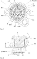
Figure 1 shows a reduced section of a priorart gear housing 1 of a rock drilling machine. The upper part, known as the shank adapter, of adrill steel 2 can be seen in the centre of thegear housing 1. The shank adapter is externally provided with splines. The shank adapter is inserted into a knowndriver 3 that is provided withinternal splines 4 that correspond to the splines of the shank adapter. Thedriver 3 is provided with an external polygonal profile and is mounted into arotation chuck 5 that has an internal polygonal profile that corresponds to the polygonal profile of thedriver 3. Therotation chuck 5 is arranged on bearings in thegear housing 1 and is rotated by the rotational motor of the rock drilling machine through a gear (not shown in the drawing). The torque that is transferred may amount to 1000 Nm or more. DocumentWO 86/02694 A1
The cross-section of thedriver 3 is limited outwards by curves, united to form a closedfigure 6 that is approximately described by a polygon with threesides 7 and threecorners 8. This type of united figure is normally known as a "polygon profile". Thefigure 6 is transversed by threeimaginary lines 9 of symmetry, drawn from the centre of thedriver 3 and passing through thecorners 8 of thefigure 6 such that these are symmetrically distributed around thelines 9 of symmetry.
The cross-section of thedriver 3 is limited inwards by thesplines 4 with eightspline teeth 10 and eightspline spaces 11. The drawing makes it clear that it is possible to arrange only one of the eightspline spaces 11 symmetrically around any one of the threelines 9 of symmetry. When one of thespline spaces 11 is arranged symmetrically around the uppermost of thelines 9 of symmetry, two of thespline teeth 10 acquire an asymmetric distribution around the twolower lines 9 of symmetry. Similar results would have been obtained if one of thespline teeth 10 had been initially taken. The asymmetry leads to certain parts being subject to considerably higher load than other parts of thedriver 3. -
Figure 2 shows an enlarged cross-section of one of thespline spaces 11 of theprior art driver 3, the shank adapter of thedrill steel 2 and therotation chuck 5 fromFigure 1 . The direction of rotation of therotation chuck 5 is shown by an arrow at the bottom. Thedriver 3 is arranged such that the ratio between the diameter d2 of the bottom circle of thespline 4 and the diameter d1 of the top circle is 1.38. The diameter D2 of the top circle of the spline teeth of the shank adapter is adapted such that it constitutes approximately 98% of the diameter d2 of the bottom circle of thesplines 4 of thedriver 3. The arrangement and the contact pressure between thespline teeth 10 of the shank adapter and thedriver 3 lead to small amounts of the material of thedriver 3 being pressed down to theroot radii 12 of thespline spaces 11 during the transfer of torque. The material that is pressed down constitutes fracture notches orburrs 13 along theradii 12 and impairs in this way its function of protecting from fatigue failure. The drawing shows how theseburrs 13 initiate the formation of cracks in theroot radii 12.
The aim of the present invention is to obtain, according to the claims, a driver and a rock drilling machine in which the previously described disadvantages are overcome. The polygonal profile and the splines are arranged in the present invention in an innovative manner that reduces the loads and distributes them symmetrically in the driver. The splines of the driver are so designed that a burr that arises as a consequence of wear is separated from the bottom of the radius. An additional advantage of the invention is that it can be introduced without significant increase in the outer dimensions of the gear housing.
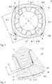
The invention will be described in more detail with the aid of the attached drawings,Figures 3-7 .Figure 3 shows a reduced cross-section of a driver according to the present invention.Figure 4 shows an enlarged cross-section in detail of the driver inFigure 3 , mounted the gear housing of a rock drilling machine.Figures 5-7 show alternative designs of the splines of the driver. -
Figure 3 shows a cross-section of adriver 3. The driver has essentially the same cross-section along its complete length. The length of thedriver 3 is adapted such that an acceptable contact pressure is obtained during the transfer of torque. Thedriver 3 is made from bronze, but may be made from cast iron or other material with similar frictional properties.
The cross-section of thedriver 3 is limited outwards by curves, or to be more precise arcs, united to form a closedfigure 6 . The closedfigure 6 in the present invention comprises foursides 7 and fourcorners 8 and can be approximately described by a convex polygon. A polygon is defined as a plane figure that is limited by straight lines, i.e. by straight curves. If straight lines are drawn between the intersection points of the imaginary extensions of thesides 7 of the closedfigure 6 , a polygon is formed. (The extensions and the polygon are shown in the drawing by dashed lines.) This fact defines the significance of the concept of "approximately" in this context.
Eachside 7 comprises an arc of a circle and all of the arcs of the circles for allsides 7 have the same radius and length. Thecorners 8 are arranged in a similar manner. Eachcorner 8 comprises an arc of a circle and all of the arcs of the circles for allcorners 8 have the same radius and length. It is also possible to allow thesides 7 or thecorners 8 to comprise other types of arcs and/or curves, than arcs of a circle. The connections between the arcs are arranged at points at which the tangents to the connected arcs coincide. The result of this is that high concentrations of tension do not arise in thedriver 3.
The cross-section of thedriver 3 is limited inwards bysplines 4 that comprise a number of spline teeth, the number of which is divisible by 4, for example, one spline set 4 with eightspline teeth 10 and eightspline spaces 11. It is also possible to arrange thesplines 4 to have twelve or sixteenspline teeth 10. Thesplines 4 are arranged such that four of thespline teeth 10 acquire a symmetrical distribution aroundimaginary lines 9 of symmetry that extend from the centre of thedriver 3 through the closedfigure 6 . Thelines 9 of symmetry have been drawn such that thefigure 6 is symmetrically distributed around thelines 9 of symmetry. It is optimal if thesplines 4 are arranged with eight or twelvespline teeth 10 and such that four of thespline teeth 10 acquire a symmetrical distribution aroundimaginary lines 9 of symmetry that extend from the centre of thedriver 3 through thecorners 8 of the closedfigure 6 . The arrangement ensures that loads are minimal and symmetrically distributed within thedriver 3. These positive properties are independent of the direction of rotation of thedriver 3, and thus the risk of erroneous assembly is small. It is possible also to distribute four of thespline spaces 11 of thesplines 4 symmetrically around thelines 9 of symmetry through thecorners 8. The loads in thedriver 3 will in this case be somewhat greater, but they will still be lower than in the previously described prior art driver.
Thespline teeth 10 andspline spaces 11 of thesplines 4 can be arranged also asymmetrically around thelines 9 of symmetry through thecorners 8. While it is true that the loads will acquire a displaced symmetrical distribution in thedriver 3 during the transfer of torque, this distribution may even so be advantageous for the transfer in a specified direction of rotation. Thedriver 3 according to the latter design must be assembled such that it acquires the specified direction of rotation.
The relationship between the diameter d2 of the bottom circle of thesplines 4 and the diameter d1 of the top circle is arranged to be greater than in the prior art driver. (Both d1 and d2 are shown with dashed circles in the figure.) This brings advantages that will be described in more detail in association withFigure 4 . Good results can be achieved at a ratio of 1.39 or higher, for example a ratio of 1.48 ± 0.02. It is, however, best to arrange thesplines 4 such that the ratio d2/d1 is 1.48. Greater ratios that 1.48 can require significant increases in the outer dimensions of the gear housing. -
Figure 4 shows how the new ratio d2/d1 = 1.48 (as shown inFigure 3 ) contributes to creatingchambers 14 between the top of the spline teeth of the shank adapter (the drill steel 2) and the bottom of thespline spaces 11 of thedriver 3. The shank adapter of thedrill steel 2 will therefore be controlled radially by the tops and the flanks of thespline teeth 10 of thesplines 4. The drawing shows also how the diameter D2 of the top circle of the spline teeth of the shank adapter constitutes approximately 95% of the diameter d2 of the bottom circle of thesplines 4 of thedriver 3. Aburr 13 forms as a consequence of wear, in accordance with the same process as has been previously described in association withFigure 2 . However, due to thechambers 14, theseburrs 13 are never pressed so deeply down into the bottoms of thespline spaces 11 such that they reach theroot radii 12 at the transition to thespline teeth 10. Theburrs 13 can therefore be said to be separated from theroot radii 12, and thenew driver 3 is in this respect better protected against fatigue failure than the prior art drivers shown inFigures 1-2 . - It is preferable that the
driver 3 be arranged such that thechambers 14 are created between the top of all of the spline teeth of the shank adapter (the drill steel 2) and the bottom of allspline spaces 11 of thedriver 3 in order to eliminate fracture notches orburrs 13 also in the radii that experience the least load. It should, however, be noted that thedriver 3 can be arranged such that only one or a few of the spline teeth of the shank adapter (the drill steel 2) make contact with the bottom in only one or a few of thespline spaces 11 of thedriver 3, as is shown inFigure 7 . It is namely the case inFigure 7 that the ratio between the diameter d2 (not shown in the drawing) of the bottom circle of thesplines 4 and the diameter d1 (not shown in the drawing) of the top circle is not the same for allspline spaces 11 of thedriver 3. - The bottoms of the
spline spaces 11 in thesplines 4 are arranged inFigures 3-4 as arcs of a circle with a diameter of the bottom circle equal to d2.Figure 5 and Figure 6 show alternative arrangements of thespline spaces 11 of thesplines 4. The bottoms inFigure 5 comprise an arc of a circle with a diameter that is considerably smaller than the diameter d2 of the bottom circle. The bottoms inFigure 6 comprise a straight line and semicircular arcs at the transition to thespline teeth 10. The tops of thespline teeth 10 of thesplines 4 are arranged as arcs of a circle with a diameter of the top circle equal to d1. It is, however, possible to arrange the tops with other diameters or other curves, or other diameters and other curves, than arcs of a circle. The diameter d2 of the bottom circle and the diameter d1 of the top circle are defined in the arrangements described above, and in similar designs, as the diameters of the imaginary circles (shown with dashed lines in the drawings) that can be narrowly placed with their curves in the region between the circles. - The new arrangement of the
splines 4 of thedriver 3 has been introduced in the description above such that it includes allspline teeth 10 andspline spaces 11 of thesplines 4. It is, however, possible under certain circumstances to arrange some of thespline teeth 10 andspline spaces 11 of thesplines 4 according to the design of the present invention and the remainder of the spline teeth and spline spaces according to the design of the splines in prior art drivers. Such a "combined" driver is to be considered to lie within the scope of the claims of the present application.
Claims (10)
- A driver (3) for the transfer of torque and rotation from a rotation chuck (5) to a drill steel (2), whereby the cross-section of the driver (3) is limited outwards by curves, in particular by arcs, united to form a closed figure (6) that can be approximately described as a polygon, and limited inwards by splines (4), characterised in that the figure (6) comprises four sides (7) and four corners (8), and in that the splines (4) comprise a number of spline teeth (10), the number of which is divisible by four.
- The driver (3) according to claim 1, characterised in that the splines (4) comprise eight, twelve or sixteen spline teeth (10).
- The driver (3) according to claim 1 or 2, characterised in that four of the spline teeth (10) or spline spaces (11) of the splines (4) are symmetrically distributed around lines (9) of symmetry through the figure (6).
- The driver (3) according to claim 1 or 2, characterised in that four of the spline teeth (10) or spline spaces (11) of the splines (4) are asymmetrically distributed around lines (9) of symmetry through the figure (6).
- The driver (3) according to claim 3 or 4, characterised in that the said lines (9) of symmetry extend through the corners (8).
- The driver (3) according to any one of claims 1-5, characterised in that each side (7) comprises an arc of a circle and in that the arcs of a circle of all sides (7) have the same radius and length, in that each corner (8) comprises an arc of a circle and in that the arcs of a circle of all corners (8) have the same radius and length.
- The driver (3) according to claim 6, characterised in that the connections between the arcs are arranged at points at which the tangents to the connected arcs coincide.
- The driver (3) according to any one of claims 1-7, characterised in that the ratio between the diameter (d2) of the bottom circle of the splines (4) and the diameter (d1) of the top circle of at least one of the spline spaces (11) is 1.39 or greater.
- The driver (3) according to any one of claims 1-7, characterised in that the ratio between the diameter (d2) of the bottom circle of the splines (4) and the diameter (d1) of the top circle of at least one of the spline spaces (11) is 1.48 ± 0.02.
- A rock drilling machine comprising a rotation chuck (5) and a driver (3) for the transfer of torque and rotation from the rotation chuck (5) to a drill steel (2), characterised in that the driver (3) is constructed according to any one of claims 1-9.
Applications Claiming Priority (2)
| Application Number | Priority Date | Filing Date | Title |
|---|---|---|---|
| SE1000703A SE534930C2 (en) | 2010-06-30 | 2010-06-30 | Carriers for transferring torque and rotation to a drill steel and rock drill |
| PCT/SE2011/050690 WO2012002876A1 (en) | 2010-06-30 | 2011-06-01 | Driver for torque and rotation transfer from a rotational chuck to a drill steel |
Publications (3)
| Publication Number | Publication Date |
|---|---|
| EP2588706A1 EP2588706A1 (en) | 2013-05-08 |
| EP2588706A4 EP2588706A4 (en) | 2017-12-06 |
| EP2588706B1 true EP2588706B1 (en) | 2018-12-26 |
Family
ID=45402356
Family Applications (1)
| Application Number | Title | Priority Date | Filing Date |
|---|---|---|---|
| EP11801233.5A Active EP2588706B1 (en) | 2010-06-30 | 2011-06-01 | Driver for torque and rotation transfer from a rotational chuck to a drill steel |
Country Status (10)
| Country | Link |
|---|---|
| US (1) | US10174565B2 (en) |
| EP (1) | EP2588706B1 (en) |
| JP (1) | JP6061847B2 (en) |
| CN (1) | CN102985635B (en) |
| AU (1) | AU2011271712B2 (en) |
| CA (1) | CA2803297C (en) |
| ES (1) | ES2716556T3 (en) |
| SE (1) | SE534930C2 (en) |
| WO (1) | WO2012002876A1 (en) |
| ZA (1) | ZA201208893B (en) |
Families Citing this family (12)
| Publication number | Priority date | Publication date | Assignee | Title |
|---|---|---|---|---|
| US10221887B2 (en) | 2012-12-06 | 2019-03-05 | The Hive Global, Inc | Self locking bearing preload adjuster |
| US10562588B2 (en) | 2015-09-01 | 2020-02-18 | The Hive Global, Inc | Bicycle cassette with locking connection |
| CN107023585B (en) * | 2016-02-02 | 2020-11-03 | 索恩格汽车部件(中国)有限公司 | Spline connection structure reaches engine starting motor including it |
| US20170261039A1 (en) * | 2016-03-08 | 2017-09-14 | Faraday&Future Inc. | Shaft to shaft screw-less coupling |
| US11142280B2 (en) * | 2016-03-24 | 2021-10-12 | The Hive Global, Inc. | Bicycle crank with spindle attachment structure |
| CN111542471A (en) | 2017-08-21 | 2020-08-14 | 劲锋铁马股份有限公司 | Bicycle cone pulley with clamping connection |
| US10859122B2 (en) | 2017-08-25 | 2020-12-08 | Kennametal Inc. | Spline drive drill steel couplers |
| US11932351B2 (en) | 2020-07-17 | 2024-03-19 | The Hive Global, Inc. | Conical bicycle cassette sprocket structure |
| WO2022204158A1 (en) | 2021-03-26 | 2022-09-29 | The Hive Global, Inc. | Telescopic bicycle seatpost with adjustable height and fixed frame insertion |
| CN113464062B (en) * | 2021-07-12 | 2024-07-09 | 江西沃思德凿岩液压有限公司 | Rock drill |
| US12030586B2 (en) | 2021-07-12 | 2024-07-09 | The Hive Global, Inc. | Seal for bicycle crank with differential chainring motion |
| EP4386174B1 (en) * | 2022-12-13 | 2026-04-22 | Sandvik Mining and Construction Oy | Rotating sleeve, rock drilling machine and method |
Family Cites Families (30)
| Publication number | Priority date | Publication date | Assignee | Title |
|---|---|---|---|---|
| US3111261A (en) * | 1960-05-02 | 1963-11-19 | Curtiss Wright Corp | Rotor and bearing construction for rotary mechanisms |
| US3396554A (en) * | 1966-04-14 | 1968-08-13 | Gen Motors Corp | Retaining ring for a universal joint member |
| DE1574310A1 (en) * | 1967-08-14 | 1971-06-24 | Bemberg Ag | Device for the slip-free coupling of the winding tube and drive shaft when winding threads or foils |
| US3666024A (en) * | 1970-07-29 | 1972-05-30 | Richard W Beaumont | Rock drill |
| SE364755B (en) | 1972-07-07 | 1974-03-04 | Atlas Copco Ab | |
| SE398066B (en) * | 1975-03-18 | 1977-12-05 | Atlas Copco Ab | METHOD AND DEVICE FOR STRIKING PROCESSING FOR DAMPING THE RECYCLE FROM A WORKING TOOL |
| US4194581A (en) * | 1975-03-22 | 1980-03-25 | Walter Hans P | Deep drill hammer |
| US4134460A (en) * | 1976-05-15 | 1979-01-16 | Firm. Ing. Gunter Klemm | Hydraulic drilling device |
| SE423253B (en) * | 1976-11-04 | 1982-04-26 | Atlas Copco Ab | Rock drilling equipment |
| US4153260A (en) | 1978-06-02 | 1979-05-08 | Dana Corporation | Slip spline seal assembly |
| DE3242274C1 (en) * | 1982-11-15 | 1984-05-30 | Danfoss A/S, Nordborg | Tooth coupling between pinion and cardan shaft of an internal-axis rotary piston machine |
| AU5063185A (en) * | 1984-10-22 | 1986-05-15 | A.B. Atlas Copco | A rock drill |
| SE457623B (en) | 1987-04-21 | 1989-01-16 | Sandvik Ab | TOOL CONNECTION |
| US5305835A (en) * | 1992-09-23 | 1994-04-26 | Ingersoll-Rand Company | Nonrotary piston for jackhammer and removable splined nut therefor |
| JPH08193625A (en) | 1995-01-17 | 1996-07-30 | Matsui Seisakusho:Kk | Spline shaft |
| US5632301A (en) * | 1996-06-07 | 1997-05-27 | Mcgard, Inc. | Tamper resistant construction for hydrant |
| JPH1089373A (en) * | 1996-09-11 | 1998-04-07 | Koyo Seiko Co Ltd | Elastic shaft joint |
| US5848334A (en) * | 1996-11-18 | 1998-12-08 | Xerox Corporation | Drive coupling with plural intimate planar contact |
| JP3684762B2 (en) | 1997-06-04 | 2005-08-17 | 日本精工株式会社 | Elastic shaft coupling |
| US5827122A (en) * | 1997-06-06 | 1998-10-27 | Neapco, Inc. | Radial free motion driveline |
| DE50103741D1 (en) * | 2001-01-19 | 2004-10-28 | Visteon Global Tech Inc | Shaft-hub-connection |
| SE526285C2 (en) * | 2004-10-22 | 2005-08-16 | Atlas Copco Rock Drills Ab | drill Bushing |
| DE102004053783A1 (en) * | 2004-11-08 | 2006-05-11 | Robert Bosch Gmbh | Hand tool, in particular drill or screwdriver |
| US7445558B2 (en) * | 2006-05-03 | 2008-11-04 | American Axle & Manufacturing, Inc. | Driveshaft assembly with piloted flange connection |
| KR20090042857A (en) * | 2006-08-23 | 2009-04-30 | 노이마이어 테크포르 홀딩 게엠베하 | Connecting device between shaft journal and joint part |
| JP2008073793A (en) * | 2006-09-20 | 2008-04-03 | Hitachi Koki Co Ltd | Impact tools |
| WO2008088007A1 (en) * | 2007-01-17 | 2008-07-24 | Ntn Corporation | Constant velocity universal joint |
| US7891902B2 (en) * | 2007-06-19 | 2011-02-22 | Robotzone, Llc | Hobby servo shaft adapter |
| DE102009023449A1 (en) * | 2009-05-30 | 2010-12-16 | Piv Drives Gmbh | Shaft-hub connection with polygonal profile |
| DE102009024455A1 (en) * | 2009-06-10 | 2011-01-05 | Audi Ag | Built-shaft element, in particular built camshaft for valve-controlled internal combustion engines |
-
2010
- 2010-06-30 SE SE1000703A patent/SE534930C2/en unknown
-
2011
- 2011-06-01 ES ES11801233T patent/ES2716556T3/en active Active
- 2011-06-01 JP JP2013518324A patent/JP6061847B2/en active Active
- 2011-06-01 US US13/261,539 patent/US10174565B2/en active Active
- 2011-06-01 AU AU2011271712A patent/AU2011271712B2/en active Active
- 2011-06-01 EP EP11801233.5A patent/EP2588706B1/en active Active
- 2011-06-01 CA CA2803297A patent/CA2803297C/en active Active
- 2011-06-01 CN CN201180032053.6A patent/CN102985635B/en active Active
- 2011-06-01 WO PCT/SE2011/050690 patent/WO2012002876A1/en not_active Ceased
-
2012
- 2012-11-26 ZA ZA2012/08893A patent/ZA201208893B/en unknown
Non-Patent Citations (1)
| Title |
|---|
| None * |
Also Published As
| Publication number | Publication date |
|---|---|
| CA2803297C (en) | 2018-08-21 |
| ES2716556T3 (en) | 2019-06-13 |
| AU2011271712B2 (en) | 2015-11-26 |
| JP6061847B2 (en) | 2017-01-18 |
| WO2012002876A1 (en) | 2012-01-05 |
| US10174565B2 (en) | 2019-01-08 |
| SE534930C2 (en) | 2012-02-21 |
| ZA201208893B (en) | 2014-01-29 |
| CA2803297A1 (en) | 2012-01-05 |
| JP2013531754A (en) | 2013-08-08 |
| EP2588706A4 (en) | 2017-12-06 |
| US20130114999A1 (en) | 2013-05-09 |
| CN102985635A (en) | 2013-03-20 |
| AU2011271712A1 (en) | 2013-01-10 |
| CN102985635B (en) | 2014-11-12 |
| EP2588706A1 (en) | 2013-05-08 |
| SE1000703A1 (en) | 2011-12-31 |
Similar Documents
| Publication | Publication Date | Title |
|---|---|---|
| CA2803297C (en) | Driver for torque and rotation transfer from a rotational chuck to a drill steel | |
| CN100558567C (en) | Face tooth part for driveable wheel hub and wheel bearing structure using same | |
| JP6228184B2 (en) | drill | |
| KR20070104297A (en) | Tool parts and threaded joints for chip removal | |
| US8043188B2 (en) | Spider-less vehicle differential | |
| US20090252549A1 (en) | Spline Connection Structure | |
| EP4012229B1 (en) | Coaxial gear | |
| CN108779795A (en) | Axis | |
| US12053830B2 (en) | Device for transmitting torque from a drill to a drill bit | |
| SE0900325A1 (en) | Roller comprising a drive shaft and a roller ring | |
| KR101726979B1 (en) | Joint yoke for a universal joint and universal joint | |
| CN103228958B (en) | Gear mechanism having helical toothing | |
| KR20050107394A (en) | Ball screw device | |
| US20230051973A1 (en) | Device for Transmitting Torque from a Drill to a Drill Bit | |
| JP4370982B2 (en) | Thrust washer and cross shaft joint using the same | |
| KR102942674B1 (en) | Face tooth profile with forming radius | |
| JP4879501B2 (en) | High angle fixed type constant velocity universal joint | |
| TWI424124B (en) | Screw | |
| JP2007040320A (en) | Cold forged bevel gear shaft | |
| JP2007239778A (en) | Constant velocity joint | |
| US12479034B2 (en) | Device for transmitting torque from a drill to a drill bit | |
| CN218670511U (en) | Gear shaft | |
| JP4302008B2 (en) | Shaft and hub power transmission mechanism | |
| KR20190052456A (en) | Wheel bearing assembly | |
| JP2009144828A (en) | Ball-type constant velocity joint and manufacturing method thereof |
Legal Events
| Date | Code | Title | Description |
|---|---|---|---|
| PUAI | Public reference made under article 153(3) epc to a published international application that has entered the european phase |
Free format text: ORIGINAL CODE: 0009012 |
|
| 17P | Request for examination filed |
Effective date: 20121119 |
|
| AK | Designated contracting states |
Kind code of ref document: A1 Designated state(s): AL AT BE BG CH CY CZ DE DK EE ES FI FR GB GR HR HU IE IS IT LI LT LU LV MC MK MT NL NO PL PT RO RS SE SI SK SM TR |
|
| DAX | Request for extension of the european patent (deleted) | ||
| RA4 | Supplementary search report drawn up and despatched (corrected) |
Effective date: 20171106 |
|
| RIC1 | Information provided on ipc code assigned before grant |
Ipc: B25D 17/08 20060101ALI20171027BHEP Ipc: E21B 17/03 20060101AFI20171027BHEP |
|
| RAP1 | Party data changed (applicant data changed or rights of an application transferred) |
Owner name: EPIROC ROCK DRILLS AKTIEBOLAG |
|
| GRAP | Despatch of communication of intention to grant a patent |
Free format text: ORIGINAL CODE: EPIDOSNIGR1 |
|
| STAA | Information on the status of an ep patent application or granted ep patent |
Free format text: STATUS: GRANT OF PATENT IS INTENDED |
|
| INTG | Intention to grant announced |
Effective date: 20180725 |
|
| GRAS | Grant fee paid |
Free format text: ORIGINAL CODE: EPIDOSNIGR3 |
|
| GRAA | (expected) grant |
Free format text: ORIGINAL CODE: 0009210 |
|
| STAA | Information on the status of an ep patent application or granted ep patent |
Free format text: STATUS: THE PATENT HAS BEEN GRANTED |
|
| AK | Designated contracting states |
Kind code of ref document: B1 Designated state(s): AL AT BE BG CH CY CZ DE DK EE ES FI FR GB GR HR HU IE IS IT LI LT LU LV MC MK MT NL NO PL PT RO RS SE SI SK SM TR |
|
| REG | Reference to a national code |
Ref country code: GB Ref legal event code: FG4D |
|
| REG | Reference to a national code |
Ref country code: CH Ref legal event code: EP |
|
| REG | Reference to a national code |
Ref country code: DE Ref legal event code: R096 Ref document number: 602011055205 Country of ref document: DE |
|
| REG | Reference to a national code |
Ref country code: AT Ref legal event code: REF Ref document number: 1081664 Country of ref document: AT Kind code of ref document: T Effective date: 20190115 |
|
| REG | Reference to a national code |
Ref country code: IE Ref legal event code: FG4D |
|
| PG25 | Lapsed in a contracting state [announced via postgrant information from national office to epo] |
Ref country code: LT Free format text: LAPSE BECAUSE OF FAILURE TO SUBMIT A TRANSLATION OF THE DESCRIPTION OR TO PAY THE FEE WITHIN THE PRESCRIBED TIME-LIMIT Effective date: 20181226 Ref country code: BG Free format text: LAPSE BECAUSE OF FAILURE TO SUBMIT A TRANSLATION OF THE DESCRIPTION OR TO PAY THE FEE WITHIN THE PRESCRIBED TIME-LIMIT Effective date: 20190326 Ref country code: HR Free format text: LAPSE BECAUSE OF FAILURE TO SUBMIT A TRANSLATION OF THE DESCRIPTION OR TO PAY THE FEE WITHIN THE PRESCRIBED TIME-LIMIT Effective date: 20181226 Ref country code: LV Free format text: LAPSE BECAUSE OF FAILURE TO SUBMIT A TRANSLATION OF THE DESCRIPTION OR TO PAY THE FEE WITHIN THE PRESCRIBED TIME-LIMIT Effective date: 20181226 |
|
| REG | Reference to a national code |
Ref country code: NL Ref legal event code: MP Effective date: 20181226 |
|
| REG | Reference to a national code |
Ref country code: LT Ref legal event code: MG4D |
|
| REG | Reference to a national code |
Ref country code: NO Ref legal event code: T2 Effective date: 20181226 |
|
| PG25 | Lapsed in a contracting state [announced via postgrant information from national office to epo] |
Ref country code: SE Free format text: LAPSE BECAUSE OF FAILURE TO SUBMIT A TRANSLATION OF THE DESCRIPTION OR TO PAY THE FEE WITHIN THE PRESCRIBED TIME-LIMIT Effective date: 20181226 Ref country code: RS Free format text: LAPSE BECAUSE OF FAILURE TO SUBMIT A TRANSLATION OF THE DESCRIPTION OR TO PAY THE FEE WITHIN THE PRESCRIBED TIME-LIMIT Effective date: 20181226 Ref country code: AL Free format text: LAPSE BECAUSE OF FAILURE TO SUBMIT A TRANSLATION OF THE DESCRIPTION OR TO PAY THE FEE WITHIN THE PRESCRIBED TIME-LIMIT Effective date: 20181226 Ref country code: GR Free format text: LAPSE BECAUSE OF FAILURE TO SUBMIT A TRANSLATION OF THE DESCRIPTION OR TO PAY THE FEE WITHIN THE PRESCRIBED TIME-LIMIT Effective date: 20190327 |
|
| REG | Reference to a national code |
Ref country code: ES Ref legal event code: FG2A Ref document number: 2716556 Country of ref document: ES Kind code of ref document: T3 Effective date: 20190613 |
|
| PG25 | Lapsed in a contracting state [announced via postgrant information from national office to epo] |
Ref country code: NL Free format text: LAPSE BECAUSE OF FAILURE TO SUBMIT A TRANSLATION OF THE DESCRIPTION OR TO PAY THE FEE WITHIN THE PRESCRIBED TIME-LIMIT Effective date: 20181226 |
|
| PG25 | Lapsed in a contracting state [announced via postgrant information from national office to epo] |
Ref country code: PL Free format text: LAPSE BECAUSE OF FAILURE TO SUBMIT A TRANSLATION OF THE DESCRIPTION OR TO PAY THE FEE WITHIN THE PRESCRIBED TIME-LIMIT Effective date: 20181226 Ref country code: PT Free format text: LAPSE BECAUSE OF FAILURE TO SUBMIT A TRANSLATION OF THE DESCRIPTION OR TO PAY THE FEE WITHIN THE PRESCRIBED TIME-LIMIT Effective date: 20190426 Ref country code: CZ Free format text: LAPSE BECAUSE OF FAILURE TO SUBMIT A TRANSLATION OF THE DESCRIPTION OR TO PAY THE FEE WITHIN THE PRESCRIBED TIME-LIMIT Effective date: 20181226 |
|
| PG25 | Lapsed in a contracting state [announced via postgrant information from national office to epo] |
Ref country code: SK Free format text: LAPSE BECAUSE OF FAILURE TO SUBMIT A TRANSLATION OF THE DESCRIPTION OR TO PAY THE FEE WITHIN THE PRESCRIBED TIME-LIMIT Effective date: 20181226 Ref country code: IS Free format text: LAPSE BECAUSE OF FAILURE TO SUBMIT A TRANSLATION OF THE DESCRIPTION OR TO PAY THE FEE WITHIN THE PRESCRIBED TIME-LIMIT Effective date: 20190426 Ref country code: SM Free format text: LAPSE BECAUSE OF FAILURE TO SUBMIT A TRANSLATION OF THE DESCRIPTION OR TO PAY THE FEE WITHIN THE PRESCRIBED TIME-LIMIT Effective date: 20181226 Ref country code: EE Free format text: LAPSE BECAUSE OF FAILURE TO SUBMIT A TRANSLATION OF THE DESCRIPTION OR TO PAY THE FEE WITHIN THE PRESCRIBED TIME-LIMIT Effective date: 20181226 Ref country code: RO Free format text: LAPSE BECAUSE OF FAILURE TO SUBMIT A TRANSLATION OF THE DESCRIPTION OR TO PAY THE FEE WITHIN THE PRESCRIBED TIME-LIMIT Effective date: 20181226 |
|
| REG | Reference to a national code |
Ref country code: DE Ref legal event code: R097 Ref document number: 602011055205 Country of ref document: DE |
|
| PG25 | Lapsed in a contracting state [announced via postgrant information from national office to epo] |
Ref country code: DK Free format text: LAPSE BECAUSE OF FAILURE TO SUBMIT A TRANSLATION OF THE DESCRIPTION OR TO PAY THE FEE WITHIN THE PRESCRIBED TIME-LIMIT Effective date: 20181226 |
|
| PLBE | No opposition filed within time limit |
Free format text: ORIGINAL CODE: 0009261 |
|
| STAA | Information on the status of an ep patent application or granted ep patent |
Free format text: STATUS: NO OPPOSITION FILED WITHIN TIME LIMIT |
|
| 26N | No opposition filed |
Effective date: 20190927 |
|
| PG25 | Lapsed in a contracting state [announced via postgrant information from national office to epo] |
Ref country code: MC Free format text: LAPSE BECAUSE OF FAILURE TO SUBMIT A TRANSLATION OF THE DESCRIPTION OR TO PAY THE FEE WITHIN THE PRESCRIBED TIME-LIMIT Effective date: 20181226 |
|
| REG | Reference to a national code |
Ref country code: CH Ref legal event code: PL |
|
| PG25 | Lapsed in a contracting state [announced via postgrant information from national office to epo] |
Ref country code: SI Free format text: LAPSE BECAUSE OF FAILURE TO SUBMIT A TRANSLATION OF THE DESCRIPTION OR TO PAY THE FEE WITHIN THE PRESCRIBED TIME-LIMIT Effective date: 20181226 |
|
| REG | Reference to a national code |
Ref country code: BE Ref legal event code: MM Effective date: 20190630 |
|
| PG25 | Lapsed in a contracting state [announced via postgrant information from national office to epo] |
Ref country code: TR Free format text: LAPSE BECAUSE OF FAILURE TO SUBMIT A TRANSLATION OF THE DESCRIPTION OR TO PAY THE FEE WITHIN THE PRESCRIBED TIME-LIMIT Effective date: 20181226 |
|
| PG25 | Lapsed in a contracting state [announced via postgrant information from national office to epo] |
Ref country code: BE Free format text: LAPSE BECAUSE OF NON-PAYMENT OF DUE FEES Effective date: 20190630 Ref country code: CH Free format text: LAPSE BECAUSE OF NON-PAYMENT OF DUE FEES Effective date: 20190630 Ref country code: LU Free format text: LAPSE BECAUSE OF NON-PAYMENT OF DUE FEES Effective date: 20190601 Ref country code: LI Free format text: LAPSE BECAUSE OF NON-PAYMENT OF DUE FEES Effective date: 20190630 |
|
| PG25 | Lapsed in a contracting state [announced via postgrant information from national office to epo] |
Ref country code: CY Free format text: LAPSE BECAUSE OF FAILURE TO SUBMIT A TRANSLATION OF THE DESCRIPTION OR TO PAY THE FEE WITHIN THE PRESCRIBED TIME-LIMIT Effective date: 20181226 |
|
| PG25 | Lapsed in a contracting state [announced via postgrant information from national office to epo] |
Ref country code: HU Free format text: LAPSE BECAUSE OF FAILURE TO SUBMIT A TRANSLATION OF THE DESCRIPTION OR TO PAY THE FEE WITHIN THE PRESCRIBED TIME-LIMIT; INVALID AB INITIO Effective date: 20110601 Ref country code: MT Free format text: LAPSE BECAUSE OF FAILURE TO SUBMIT A TRANSLATION OF THE DESCRIPTION OR TO PAY THE FEE WITHIN THE PRESCRIBED TIME-LIMIT Effective date: 20181226 |
|
| REG | Reference to a national code |
Ref country code: AT Ref legal event code: UEP Ref document number: 1081664 Country of ref document: AT Kind code of ref document: T Effective date: 20181226 |
|
| PG25 | Lapsed in a contracting state [announced via postgrant information from national office to epo] |
Ref country code: MK Free format text: LAPSE BECAUSE OF FAILURE TO SUBMIT A TRANSLATION OF THE DESCRIPTION OR TO PAY THE FEE WITHIN THE PRESCRIBED TIME-LIMIT Effective date: 20181226 |
|
| PGFP | Annual fee paid to national office [announced via postgrant information from national office to epo] |
Ref country code: IT Payment date: 20220621 Year of fee payment: 12 Ref country code: IE Payment date: 20220627 Year of fee payment: 12 Ref country code: GB Payment date: 20220628 Year of fee payment: 12 |
|
| PGFP | Annual fee paid to national office [announced via postgrant information from national office to epo] |
Ref country code: AT Payment date: 20220519 Year of fee payment: 12 |
|
| PGFP | Annual fee paid to national office [announced via postgrant information from national office to epo] |
Ref country code: ES Payment date: 20220701 Year of fee payment: 12 |
|
| REG | Reference to a national code |
Ref country code: AT Ref legal event code: MM01 Ref document number: 1081664 Country of ref document: AT Kind code of ref document: T Effective date: 20230601 |
|
| GBPC | Gb: european patent ceased through non-payment of renewal fee |
Effective date: 20230601 |
|
| REG | Reference to a national code |
Ref country code: IE Ref legal event code: MM4A |
|
| PG25 | Lapsed in a contracting state [announced via postgrant information from national office to epo] |
Ref country code: IE Free format text: LAPSE BECAUSE OF NON-PAYMENT OF DUE FEES Effective date: 20230601 |
|
| PG25 | Lapsed in a contracting state [announced via postgrant information from national office to epo] |
Ref country code: AT Free format text: LAPSE BECAUSE OF NON-PAYMENT OF DUE FEES Effective date: 20230601 |
|
| PG25 | Lapsed in a contracting state [announced via postgrant information from national office to epo] |
Ref country code: IE Free format text: LAPSE BECAUSE OF NON-PAYMENT OF DUE FEES Effective date: 20230601 Ref country code: AT Free format text: LAPSE BECAUSE OF NON-PAYMENT OF DUE FEES Effective date: 20230601 Ref country code: GB Free format text: LAPSE BECAUSE OF NON-PAYMENT OF DUE FEES Effective date: 20230601 |
|
| REG | Reference to a national code |
Ref country code: ES Ref legal event code: FD2A Effective date: 20240729 |
|
| PG25 | Lapsed in a contracting state [announced via postgrant information from national office to epo] |
Ref country code: IT Free format text: LAPSE BECAUSE OF NON-PAYMENT OF DUE FEES Effective date: 20230601 |
|
| PG25 | Lapsed in a contracting state [announced via postgrant information from national office to epo] |
Ref country code: ES Free format text: LAPSE BECAUSE OF NON-PAYMENT OF DUE FEES Effective date: 20230602 |
|
| PG25 | Lapsed in a contracting state [announced via postgrant information from national office to epo] |
Ref country code: ES Free format text: LAPSE BECAUSE OF NON-PAYMENT OF DUE FEES Effective date: 20230602 |
|
| PGFP | Annual fee paid to national office [announced via postgrant information from national office to epo] |
Ref country code: FI Payment date: 20250520 Year of fee payment: 15 |
|
| PGFP | Annual fee paid to national office [announced via postgrant information from national office to epo] |
Ref country code: DE Payment date: 20250520 Year of fee payment: 15 |
|
| PGFP | Annual fee paid to national office [announced via postgrant information from national office to epo] |
Ref country code: NO Payment date: 20250522 Year of fee payment: 15 |
|
| PGFP | Annual fee paid to national office [announced via postgrant information from national office to epo] |
Ref country code: FR Payment date: 20250520 Year of fee payment: 15 |