EP2587775B1 - Pouch and mobile terminal having the same - Google Patents
Pouch and mobile terminal having the same Download PDFInfo
- Publication number
- EP2587775B1 EP2587775B1 EP12189489.3A EP12189489A EP2587775B1 EP 2587775 B1 EP2587775 B1 EP 2587775B1 EP 12189489 A EP12189489 A EP 12189489A EP 2587775 B1 EP2587775 B1 EP 2587775B1
- Authority
- EP
- European Patent Office
- Prior art keywords
- terminal body
- mobile terminal
- pouch
- unit
- slide unit
- Prior art date
- Legal status (The legal status is an assumption and is not a legal conclusion. Google has not performed a legal analysis and makes no representation as to the accuracy of the status listed.)
- Not-in-force
Links
Images


Classifications
-
- H—ELECTRICITY
- H04—ELECTRIC COMMUNICATION TECHNIQUE
- H04M—TELEPHONIC COMMUNICATION
- H04M1/00—Substation equipment, e.g. for use by subscribers
- H04M1/02—Constructional features of telephone sets
- H04M1/04—Supports for telephone transmitters or receivers
-
- H—ELECTRICITY
- H04—ELECTRIC COMMUNICATION TECHNIQUE
- H04B—TRANSMISSION
- H04B1/00—Details of transmission systems, not covered by a single one of groups H04B3/00 - H04B13/00; Details of transmission systems not characterised by the medium used for transmission
- H04B1/38—Transceivers, i.e. devices in which transmitter and receiver form a structural unit and in which at least one part is used for functions of transmitting and receiving
-
- H—ELECTRICITY
- H04—ELECTRIC COMMUNICATION TECHNIQUE
- H04M—TELEPHONIC COMMUNICATION
- H04M1/00—Substation equipment, e.g. for use by subscribers
- H04M1/02—Constructional features of telephone sets
-
- H—ELECTRICITY
- H04—ELECTRIC COMMUNICATION TECHNIQUE
- H04M—TELEPHONIC COMMUNICATION
- H04M1/00—Substation equipment, e.g. for use by subscribers
- H04M1/02—Constructional features of telephone sets
- H04M1/0202—Portable telephone sets, e.g. cordless phones, mobile phones or bar type handsets
- H04M1/0206—Portable telephones comprising a plurality of mechanically joined movable body parts, e.g. hinged housings
- H04M1/0241—Portable telephones comprising a plurality of mechanically joined movable body parts, e.g. hinged housings using relative motion of the body parts to change the operational status of the telephone set, e.g. switching on/off, answering incoming call
-
- H—ELECTRICITY
- H04—ELECTRIC COMMUNICATION TECHNIQUE
- H04M—TELEPHONIC COMMUNICATION
- H04M1/00—Substation equipment, e.g. for use by subscribers
- H04M1/02—Constructional features of telephone sets
- H04M1/0202—Portable telephone sets, e.g. cordless phones, mobile phones or bar type handsets
- H04M1/0206—Portable telephones comprising a plurality of mechanically joined movable body parts, e.g. hinged housings
- H04M1/0208—Portable telephones comprising a plurality of mechanically joined movable body parts, e.g. hinged housings characterized by the relative motions of the body parts
- H04M1/0235—Slidable or telescopic telephones, i.e. with a relative translation movement of the body parts; Telephones using a combination of translation and other relative motions of the body parts
- H04M1/0237—Sliding mechanism with one degree of freedom
Definitions
- This specification relates to a pouch and a mobile terminal having a main body capable of being received (accommodated) in the pouch.
- Mobile terminals are electronic devices which are portable and have at least one of voice and telephone call functions, information input and/or output functions, a data storage function and the like.
- the mobile terminal can be allowed to capture still images or moving images, play music or video files, play games, receive broadcast and the like, so as to be implemented as an integrated multimedia player.
- design factors include structural changes and improvement for making an appearance of the mobile terminal better.
- the mobile terminals are affected by external environments, such as moisture, dust, impact and the like during usage. This leads to production of cases, pouches and the like having a function of making the appearance of the mobile terminal more attractive as well as a function of simply protecting the mobile terminal from the external environments.
- a pouch and a mobile terminal having a terminal body capable of being received within the pouch may be regarded. Examples and possible embodiments are disclosed in documents US 2009/135555 A1 and US 2009/154082 A1 .
- an aspect of the detailed description is to provide a pouch capable of receiving a terminal body in various states.
- Another aspect of the detailed description is to provide a mobile terminal capable of giving various functions to a terminal body or extending conventional functions by use of the pouch.
- a pouch for a mobile terminal including a base defining a space for receiving at least part of a terminal body therein, a slide unit disposed within the base, and relatively slidable with respect to the base along a lengthwise direction of the terminal body, the slide unit supporting the terminal body, an elastic unit disposed between the base and the slide unit to apply an elastic force, a guide unit configured to guide the relative sliding of the slide unit, and a locking unit configured to lock and unlock the slide unit at and from a preset position of the base.
- the slide unit may be slidable between a first state in which the terminal body is received in the base and a second state in which at least part of the terminal body is exposed.
- the base may include a frame disposed to obscure both side surfaces of the terminal body, and a fixed plate connected to the frame and disposed to obscure a rear surface of the terminal body.
- the slide unit may include a moving plate disposed to obscure the rear surface of the terminal body, and relatively slidable with facing the fixed plate, and a support plate extending from the moving plate, and protruding from the moving plate to support the terminal body.
- the guide unit may include a first guide rail formed through the fixed plate and extending in one direction, a second guide rail formed through the moving plate and extending in an intersecting direction with the one direction, and a guide member inserted into the first and second guide rails and movable in response to the sliding of the slide unit.
- the guide member may include a body inserted into the first and second guide rails, and protruding portions protruding along an outer circumferential surface of the body to obscure the fixed plate and the moving plate, respectively.
- the first guide rail may be internally inclined with respect to the sliding direction of the slide unit.
- the locking unit may include a first guide rail extending portion extending from the first guide rail in the intersecting direction with the one direction, so as to receive the guide member therein such that the slide unit is fixed to a preset position, and a manipulation portion mounted onto the fixed plate to press the guide member to be placed on the first guide rail.
- the manipulation portion may be disposed adjacent to the first guide rail extending portion, and formed to be movable in one direction so as to press the guide member.
- the elastic unit may include a first elastic member configured to apply an elastic force to the slide unit in the sliding direction of the slide unit, and a second elastic member configured to apply an elastic force to the guide member in the intersecting direction with the sliding direction such that the guide member is received in the first guide rail extending portion.
- the second elastic member may be a spring having one end fixed to the moving plate and the other end fixed to the guide member.
- a mobile terminal including a terminal body having a display unit on a front surface and configured to perform a wireless communication function, and the above pouch for the mobile terminal, the pouch configured to receive the terminal body therein and having an opening for exposing at least part of the display unit.
- the terminal body may include a first connection port, and the first connection port may be electrically connected to a second connection port mounted onto a bottom surface of the base.
- the display unit may be configured to output visual information of a first mode in a state that the terminal body is separated from the pouch for the mobile terminal, while outputting visual information of a second mode when the first connection port and the second connection port are electrically connected to each other.
- the terminal body may further include a proximity sensor disposed to overlap the pouch for the mobile terminal in the first state, and configured to sense whether or not an external object is proximate.
- the display unit may output visual information of a pouch mode when the proximity sensor senses the proximity of the external object, and output visual information of a half pouch mode when the proximity sensor has not sensed the proximity of the external object.
- the display unit may be configured to output a main menu in the pouch mode, and to output sub menus of the main menu in the half pouch mode.
- First and second cameras may be mounted onto a rear surface and a front surface of the terminal body, respectively.
- the terminal body may be converted into an operating mode of the second camera, upon conversion into the second state, while operating in an operating mode of the first camera in the first state.
- the terminal body may be converted into an operating mode of a speakerphone upon conversion into the second state while operating in a phone call mode in the first state.
- the terminal body may include a main antenna configured to transmit and receive a wireless signal
- the pouch for the mobile terminal may include sub antennas installed therein to extend the wireless communication function of the terminal body.
- the sub antennas may be disposed adjacent to the main antenna with preset intervals so as to form coupling with the main antenna.
- Mobile terminals described in this specification may include cellular phones, smart phones, laptop computers, digital broadcasting terminals, personal digital assistants (PDAs), portable multimedia players (PMPs), E-books, navigators, and the like.
- PDAs personal digital assistants
- PMPs portable multimedia players
- E-books navigators, and the like.
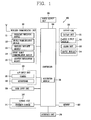
- FIG. 1 is a block diagram of a mobile terminal 10 in accordance with one exemplary embodiment.
- the mobile terminal 10 may comprise components, such as a wireless communication unit 110, an Audio/Video (A/V) input unit 120, a user input unit 130, a sensing unit 140, an output unit 150, a memory 160, an interface unit 170, a controller 180, a power supply 190 and the like.
- FIG. 1 shows the mobile terminal 10 having various components, but it is understood that implementing all of the illustrated components is not a requirement. Greater or fewer components may alternatively be implemented.
- the wireless communication unit 110 may typically include one or more modules which permit wireless communications between the mobile terminal 10 and a wireless communication system or between the mobile terminal 10 and a network within which the mobile terminal 10 is located.
- the wireless communication unit 110 may include a broadcast receiving module 111, a mobile communication module 112, a wireless Internet module 113, a short-range communication module 114, a location information module 115 and the like.
- the broadcast receiving module 111 receives a broadcast signal and/or broadcast associated information from an external broadcast managing entity via a broadcast channel.
- the broadcast channel may include a satellite channel and a terrestrial channel.
- the broadcast managing entity may indicate a server which generates and transmits a broadcast signal and/or broadcast associated information or a server which receives a pre-generated broadcast signal and/or broadcast associated information and sends them to the mobile terminal.
- the broadcast signal may be implemented as a TV broadcast signal, a radio broadcast signal, and a data broadcast signal, among others.
- the broadcast signal may further include a data broadcast signal combined with a TV or radio broadcast signal.
- broadcast associated information may include information associated with a broadcast channel, a broadcast program, a broadcast service provider, and the like.
- the broadcast associated information may be provided via a mobile communication network, and received by the mobile communication module 112.
- broadcast associated information may be implemented in various formats.
- broadcast associated information may include Electronic Program Guide (EPG) of Digital Multimedia Broadcasting (DMB), Electronic Service Guide (ESG) of Digital Video Broadcast-Handheld (DVB-H), and the like.
- EPG Electronic Program Guide
- DMB Digital Multimedia Broadcasting
- ESG Electronic Service Guide
- DVD-H Digital Video Broadcast-Handheld
- the broadcast receiving module 111 may be configured to receive digital broadcast signals transmitted from various types of broadcast systems. Such broadcast systems may include Digital Multimedia Broadcasting-Terrestrial (DMB-T), Digital Multimedia Broadcasting-Satellite (DMB-S), Media Forward Link Only (MediaFLO), Digital Video Broadcast-Handheld (DVB-H), Integrated Services Digital Broadcast-Terrestrial (ISDB-T) and the like.
- the broadcast receiving module 111 may be configured to be suitable for every broadcast system transmitting broadcast signals as well as the digital broadcasting systems.
- Broadcast signals and/or broadcast associated information received via the broadcast receiving module 111 may be stored in a suitable device, such as a memory 160.
- the mobile communication module 112 transmits/receives wireless signals to/from at least one of network entities (e.g., base station, an external mobile terminal, a server, etc.) on a mobile communication network.
- the wireless signals may include audio call signal, video (telephony) call signal, or various formats of data according to transmission/reception of text/multimedia messages.
- the wireless Internet module 113 supports wireless Internet access for the mobile terminal. This module may be internally or externally coupled to the mobile terminal 10. Examples of such wireless Internet access may include Wireless LAN (WLAN) (Wi-Fi), Wireless Broadband (Wibro), Worldwide Interoperability for Microwave Access (Wimax), High Speed Downlink Packet Access (HSDPA) and the like.
- WLAN Wireless LAN
- Wibro Wireless Broadband
- Wimax Worldwide Interoperability for Microwave Access
- HSDPA High Speed Downlink Packet Access
- the short-range communication module 114 denotes a module for short-range communications. Suitable technologies for implementing this module may include BLUETOOTHTM, Radio Frequency IDentification (RFID), Infrared Data Association (IrDA), Ultra-WideBand (UWB), ZigBeeTM, and the like.
- RFID Radio Frequency IDentification
- IrDA Infrared Data Association
- UWB Ultra-WideBand
- ZigBeeTM ZigBeeTM
- the location information module 115 denotes a module for detecting or calculating a position of a mobile terminal.
- An example of the location information module 115 may include a Global Position System (GPS) module.
- GPS Global Position System
- the AN input unit 120 is configured to provide audio or video signal input to the mobile terminal.
- the AN input unit 120 may include a camera 121 and a microphone 122.
- the camera 121 receives and processes image frames of still pictures or video obtained by image sensors in a video call mode or a capturing mode.
- the processed image frames may be displayed on a display unit 151.
- the image frames processed by the camera 121 may be stored in the memory 160 or transmitted to the exterior via the wireless communication unit 110. Two or more cameras 121 may be provided according to the configuration of the mobile terminal.
- the microphone 122 may receive an external audio signal while the mobile terminal is in a particular mode, such as a phone call mode, a recording mode, a voice recognition mode, or the like. This audio signal is processed into digital data. The processed digital data is converted for output into a format transmittable to a mobile communication base station via the mobile communication module 112 in case of the phone call mode.
- the microphone 122 may include assorted noise removing algorithms to remove noise generated in the course of receiving the external audio signal.
- the user input unit 130 may generate input data input by a user to control the operation of the mobile terminal.
- the user input unit 130 may include a keypad, a dome switch, a touchpad (e.g., static pressure/capacitance), a jog wheel, a jog switch and the like.
- the sensing unit 140 provides status measurements of various aspects of the mobile terminal. For instance, the sensing unit 140 may detect an open/close status of the mobile terminal, a change in a location of the mobile terminal 10, a presence or absence of user contact with the mobile terminal 10, the location of the mobile terminal 10, acceleration/deceleration of the mobile terminal 10, and the like, so as to generate a sensing signal for controlling the operation of the mobile terminal 10. For example, regarding a slide-type mobile terminal, the sensing unit 140 may sense whether a sliding portion of the mobile terminal is open or closed. Other examples include sensing functions, such as the sensing unit 140 sensing the presence or absence of power provided by the power supply 190, the presence or absence of a coupling or other connection between the interface unit 170 and an external device. Meanwhile, the sensing unit 140 may include a proximity sensor 141.
- the output unit 150 is configured to output an audio signal, a video signal or a tactile signal.
- the output unit 150 may include a display unit 151, an audio output module 152, an alarm unit 153 and a haptic module 154.
- the display unit 151 may output information processed in the mobile terminal 10. For example, when the mobile terminal is operating in a phone call mode, the display unit 151 will provide a User Interface (UI) or a Graphic User Interface (GUI), which includes information associated with the call. As another example, if the mobile terminal is in a video call mode or a capturing mode, the display unit 151 may additionally or alternatively display images captured and/or received, UI, or GUI.
- UI User Interface
- GUI Graphic User Interface
- the display unit 151 may be implemented using, for example, at least one of a Liquid Crystal Display (LCD), a Thin Film Transistor-Liquid Crystal Display (TFT-LCD), an Organic Light-Emitting Diode (OLED), a flexible display, a three-dimensional (3D) display, or the like.
- LCD Liquid Crystal Display
- TFT-LCD Thin Film Transistor-Liquid Crystal Display
- OLED Organic Light-Emitting Diode
- flexible display a three-dimensional (3D) display, or the like.
- Some of such displays 151 may be implemented as a transparent type or an optical transparent type through which the exterior is visible, which is referred to as 'transparent display'.
- a representative example of the transparent display may include a Transparent OLED (TOLED), and the like.
- the rear surface of the display unit 151 may also be implemented to be optically transparent. Under this configuration, a user can view an object positioned at a rear side of a terminal body through a region occupied by the display unit 151 of the terminal body.
- the display unit 151 may be implemented in two or more in number according to a configured aspect of the mobile terminal 10. For instance, a plurality of the displays 151 may be arranged on one surface to be spaced apart from or integrated with each other, or may be arranged on different surfaces.
- the display unit 151 and a touch sensitive sensor have a layered structure therebetween, the structure may be referred to as a touch screen.
- the display unit 151 may be used as an input device rather than an output device.
- the touch sensor may be implemented as a touch film, a touch sheet, a touch pad, and the like.
- the touch sensor may be configured to convert changes of a pressure applied to a specific part of the display unit 151, or a capacitance occurring from a specific part of the display unit 151, into electric input signals. Also, the touch sensor may be configured to sense not only a touched position and a touched area, but also a touch pressure.
- touch controller When touch inputs are sensed by the touch sensors, corresponding signals are transmitted to a touch controller (not shown).
- the touch controller processes the received signals, and then transmits corresponding data to the controller 180. Accordingly, the controller 180 may sense which region of the display unit 151 has been touched.
- a proximity sensor 141 may be arranged at an inner region of the mobile terminal 10 covered by the touch screen, or near the touch screen.
- the proximity sensor 141 indicates a sensor to sense presence or absence of an object approaching to a surface to be sensed, or an object disposed near a surface to be sensed, by using an electromagnetic field or infrared rays without a mechanical contact.
- the proximity sensor 141 has a longer lifespan and a more enhanced utility than a contact sensor.
- the proximity sensor 141 may include a transmissive type photoelectric sensor, a direct reflective type photoelectric sensor, a mirror reflective type photoelectric sensor, a high-frequency oscillation proximity sensor, a capacitance type proximity sensor, a magnetic type proximity sensor, an infrared rays proximity sensor, and so on.
- a capacitance type proximity sensor When the touch screen is implemented as a capacitance type, proximity of a pointer to the touch screen is sensed by changes of an electromagnetic field.
- the touch screen may be categorized into a proximity sensor.
- a status that the pointer is positioned to be proximate onto the touch screen without contact will be referred to as 'proximity touch'
- a status that the pointer substantially comes in contact with the touch screen will be referred to as 'contact touch'.
- 'proximity touch' a status that the pointer substantially comes in contact with the touch screen.
- the proximity sensor 141 senses proximity touch, and proximity touch patterns (e.g., distance, direction, speed, time, position, moving status, etc.). Information relating to the sensed proximity touch and the sensed proximity touch patterns may be output onto the touch screen.
- proximity touch patterns e.g., distance, direction, speed, time, position, moving status, etc.
- the audio output module 152 may output audio data received from the wireless communication unit 110 or stored in the memory 160, in a call-receiving mode, a call-placing mode, a recording mode, a voice recognition mode, a broadcast reception mode, and so on.
- the audio output module 152 may output audio signals relating to functions performed in the mobile terminal 10, e.g., sound alarming a call received or a message received, and so on.
- the audio output module 152 may include a receiver, a speaker, a buzzer, and so on.
- the alarm unit 153 outputs signals notifying occurrence of events from the mobile terminal 10.
- the events occurring from the mobile terminal 10 may include call received, message received, key signal input, touch input, and so on.
- the alarm unit 153 may output not only video or audio signals, but also other types of signals such as signals notifying occurrence of events in a vibration manner. Since the video or audio signals can be output through the display unit 151 or the audio output module 152, the display unit 151 and the audio output module 152 may be categorized into a part of the alarm unit 153.
- the haptic module 154 generates various tactile effects which a user can feel.
- a representative example of the tactile effects generated by the haptic module 154 includes vibration.
- Vibration generated by the haptic module 154 may have a controllable intensity, a controllable pattern, and so on. For instance, different vibration may be output in a synthesized manner or in a sequential manner.
- the haptic module 154 may generate various tactile effects, including not only vibration, but also arrangement of pins vertically moving with respect to a skin being touched (contacted), air injection force or air suction force through an injection hole or a suction hole, touch by a skin surface, presence or absence of contact with an electrode, effects by stimulus such as an electrostatic force, reproduction of cold or hot feeling using a heat absorbing device or a heat emitting device, and the like.
- the haptic module 154 may be configured to transmit tactile effects (signals) through a user's direct contact, or a user's muscular sense using a finger or a hand.
- the haptic module 154 may be implemented in two or more in number according to the configuration of the mobile terminal 10.
- the memory 160 may store a program for the processing and control of the controller 180. Alternatively, the memory 160 may temporarily store input/output data (e.g., phonebook data, messages, still images, video and the like). Also, the memory 160 may store data related to various patterns of vibrations and audio output upon the touch input on the touch screen.
- input/output data e.g., phonebook data, messages, still images, video and the like.
- the memory 160 may store data related to various patterns of vibrations and audio output upon the touch input on the touch screen.
- the memory 160 may be implemented using any type of suitable storage medium including a flash memory type, a hard disk type, a memory card type (e.g., SD or DX memory), Random Access Memory (RAM), Static Random Access Memory (SRAM), Read-Only Memory (ROM), Electrically Erasable Programmable Read-Only Memory (EEPROM), Programmable Read-Only Memory (PROM), magnetic memory, magnetic disk, optical disk, and the like. Also, the mobile terminal 10 may operate a web storage which performs the storage function of the memory 160 on the Internet.
- a flash memory type e.g., a hard disk type
- a memory card type e.g., SD or DX memory
- RAM Random Access Memory
- SRAM Static Random Access Memory
- ROM Read-Only Memory
- EEPROM Electrically Erasable Programmable Read-Only Memory
- PROM Programmable Read-Only Memory
- magnetic memory magnetic disk, optical disk, and the like.
- the mobile terminal 10 may operate a web storage which performs the storage function
- the interface unit 170 may generally be implemented to interface the mobile terminal with external devices.
- the interface unit 170 may allow a data reception from an external device, a power delivery to each component in the mobile terminal 10, or a data transmission from the mobile terminal 10 to an external device.
- the interface unit 170 may include, for example, wired/wireless headset ports, external charger ports, wired/wireless data ports, memory card ports, ports for coupling devices having an identification module, audio Input/Output (I/O) ports, video I/O ports, earphone ports, and the like.
- I/O audio Input/Output
- the identification module may be configured as a chip for storing various information required to authenticate an authority to use the mobile terminal 10, which may include a User Identity Module (UIM), a Subscriber Identity Module (SIM), and the like. Also, the device having the identification module (hereinafter, referred to as 'identification device') may be implemented in a type of smart card. Hence, the identification device can be coupled to the mobile terminal 10 via a port.
- UIM User Identity Module
- SIM Subscriber Identity Module
- the interface unit 170 may serve as a path for power to be supplied from an external cradle to the mobile terminal 10 when the mobile terminal 10 is connected to the external cradle or as a path for transferring various command signals input from the cradle by a user to the mobile terminal 10.
- Such various command signals or power input from the cradle may operate as signals for recognizing that the mobile terminal 10 has accurately been mounted to the cradle.
- the controller 180 typically controls the overall operations of the mobile terminal 10. For example, the controller 180 performs the control and processing associated with telephony calls, data communications, video calls, and the like.
- the controller 180 may include a multimedia module 181 which provides multimedia playback.
- the multimedia module 181 may be configured as part of the controller 180 or as a separate component.
- the controller 180 can perform a pattern recognition processing so as to recognize writing or drawing input on the touch screen as text or image.
- the power supply 190 provides power required by various components under the control of the controller 180.
- the provided power may be internal power, external power, or combination thereof.
- the embodiments described herein may be implemented within one or more Application Specific Integrated Circuits (ASICs), Digital Signal Processors (DSPs), Digital Signal Processing Devices (DSPDs), Programmable Logic Devices (PLDs), Field Programmable Gate Arrays (FPGAs), processors, microprocessors, other electronic units designed to perform the functions described herein, or a selective combination thereof. In some cases, such embodiments are implemented by the controller 180.
- ASICs Application Specific Integrated Circuits
- DSPs Digital Signal Processors
- DSPDs Digital Signal Processing Devices
- PLDs Programmable Logic Devices
- FPGAs Field Programmable Gate Arrays
- processors microprocessors, other electronic units designed to perform the functions described herein, or a selective combination thereof.
- microprocessors other electronic units designed to perform the functions described herein, or a selective combination thereof.
- the embodiments such as procedures and functions may be implemented together with separate software modules each of which performs at least one of functions and operations.
- the software codes can be implemented with a software application written in any suitable programming language. Also, the software codes may be stored in the memory 160 and executed by the controller 180.
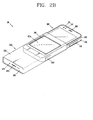
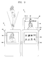
- FIG. 2A illustrates one example of the mobile terminal 10 according to this specification, which is a front perspective view showing a separated state of a terminal body 100 from a pouch 200.
- the mobile terminal 10 may include a terminal body 100 and a pouch 200 for receiving (accommodating) the terminal body 100 therein.
- the terminal body 100 may perform a wireless communication function and be configured to be received in or separated from the pouch 200.
- the pouch 200 may serve to protect the mobile terminal 10 from external environments and give attraction to the mobile terminal 10.
- the pouch 200 may include an opening 211a corresponding to the display unit 151 such that the display unit 151 can be partially exposed when the terminal body 100 is received in the pouch 200. A detailed structure of the pouch 200 will be explained later with reference to FIG. 3 .
- the mobile terminal 10 includes a bar type terminal body 100.
- a bar type terminal body 100 may be any suitable structure, such as a slide type, a folder type, a swing type, a swivel type and the like, having two or more bodies coupled to be relatively movable with each other.
- a body may include a case (or referred to as casing, housing, cover, etc.) defining an appearance of the mobile terminal 10.
- the case may be divided into a front case 101 and a rear case 102.
- a space formed between the front and rear cases 101 and 102 may accommodate various electronic components.
- At least one intermediate case may further be disposed between the front and the rear cases 101 and 102.
- Such cases may be injected using a synthetic resin or be formed of a metal, such as stainless steel (STS), titanium (Ti) or the like.
- STS stainless steel
- Ti titanium
- the terminal body is shown having a display unit 151, an audio output module 152, a camera 121, a user input unit 130/131, 132, a microphone 122, an interface unit 170, and the like.
- the display unit 151 may occupy most of a principal surface of the front case 101.
- the audio output module 152 and the camera 121 may be disposed near one of both end portions of the display unit 151, and the user input unit 131 and the microphone 122 on the other end portion of the display unit 151.
- the user input unit 132, the interface unit 170 and the like may be disposed on side surfaces of the front and rear cases 101 and 102.
- the user input unit 130 may be manipulated to allow inputting of commands for controlling operations of the mobile terminal 10, and include a plurality of first manipulation units 131, 132.
- the plurality of manipulation units 131, 132 may be referred to as a manipulating portion.
- Such manipulating portion can employ any tactile manner that a user can touch or tap for manipulation.
- the first and second manipulation units 131, 132 may be set to allow inputting of various contents.
- the first manipulation unit 131 may be configured to input commands such as START, END, SCROLL or the like
- the second manipulation unit 132 may be configured to input commands, such as a volume adjustment of sounds output from the audio output module 152, conversion of the display unit 151 into a touch recognition mode, or the like.
- FIG. 2B is a perspective view showing a received state of the terminal body 100 shown in FIG. 2A in the pouch 200 (i.e., a half pouch state).
- the terminal body 100 may be completely received in the pouch 200 (i.e., a pouch state, first state) or partially exposed according to an operating mechanism of the pouch 200 (i.e., a half pouch state, second state).
- the terminal body 100 may perform a specific function according to the received state in the pouch 200, and achieve a more extended function using the pouch 200. It may also be natural that the terminal body 100 can independently operate with being completely separated from the pouch 200.
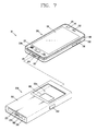
- FIG. 2C is a rear perspective view showing the separated state of the terminal body 100 shown in FIG. 2A from the pouch 200.
- a rear face of the terminal body namely, the rear case 102 may further be provided with a camera 121'.
- the camera 121' faces a direction which is opposite to a direction faced by the camera 121 (see FIG. 2A ), and may have different pixels from those of the camera 121.
- the camera 121 may operate with relatively lower pixels (lower resolution). Thus, the camera 121 may be useful when a user can capture his face and send it to another party during a video call or the like.
- the camera 121' may operate with a relatively higher pixels (higher resolution) such that it can be useful for a user to obtain higher quality pictures for later use.
- the cameras 121 and 121' may be installed in the terminal body to be rotatable or popped up.
- a flash 123 and a mirror 124 may additionally be disposed adjacent to the camera 121'.
- the flash 123 operates in conjunction with the camera 121' when taking a picture using the camera 121'.
- the mirror 124 can cooperate with the camera 121' to allow a user to photograph himself in a self-portrait mode.
- An audio output module 152' may further be disposed at a rear face of the terminal body.
- the audio output module 152' can cooperate with the audio output module 152 (see FIG. 2A ) to provide stereo output.
- the audio output module 152' may be configured to operate as a speakerphone.
- a broadcast signal receiving antenna may further be disposed at one side of the terminal body in addition to an antenna for communications, for example.
- the antenna 124 configuring a part of the broadcast receiving module 111 may be retractable into the terminal body.
- a power supply unit 190 for supplying power to the mobile terminal 10 may be mounted in the terminal body.
- the power supply unit 190 may be mounted in the terminal body 100 or detachably coupled directly onto the outside of the terminal body 100.
- FIG. 3 is a front conceptual view of the pouch, taken along the line III-III of FIG. 2A
- FIG. 4 is a sectional view taken along the line IV-IV of FIG. 3 .
- the pouch 200 may have a structure of receiving (accommodating) the terminal body 100 in a pouch state and in a half pouch state, and converting one state into another state according to a manipulation.
- the pouch 200 may include a base 210, a slide unit 220, an elastic unit 230, a guide unit 240, and a locking unit 260.
- the base 210 may form a space for receiving at least part of the terminal body 100.
- the base 210 may include an opening 210a for allowing the terminal body 100 to be inserted thereinto in one direction. This exemplary embodiment illustrates that the opening 210a is formed at an upper end of the base 210 such that the terminal body 100 can be inserted in a lengthwise direction.
- the base 210 may also include a frame 211 and a fixed plate 212.
- the frame 211 may cover both side surfaces of the terminal body 100, and include an opening 211 a (see FIG. 2A ), which is formed at a front surface thereof and corresponds to the display unit 151 to expose at least part of the display unit 151.
- the fixed plate 212 may be connected to the frame 211 and cover a rear surface of the terminal body 100.
- the frame 211 and the fixed plate 212 may be integrally formed with each other.
- the base 210 may also include a cover 213 (see FIG. 2A ) defining an appearance thereof.
- the cover 213 may shield the frame 211 and the fixed plate 212, and obtain esthetic appreciation through surface processing.
- the cover 213 may be formed of leather or synthetic resin, or of a metal such as stainless steel (STS), aluminum (Al), titanium (Ti) or the like.
- the slide unit 220 may be disposed within the base 210.
- the slide unit 220 may support the terminal body 100, and be coupled to be relatively slidable with respect to the base 210 in a lengthwise direction of the terminal body 100.
- the slide unit 220 may include a moving plate 221, and a support plate 222.
- the moving plate 221 may shield a rear surface of the terminal body 100, and be relatively slidable with facing the fixed plate 212.
- the support plate 222 may extend from the moving plate 221, and protrude from the moving plate 221 to support the terminal body 100.
- the moving plate 221 and the support plate 222 may be integrally formed with each other.
- the guide unit 240 may be configured to guide relative sliding of the slide unit 220 with respect to the base 210.
- the guide unit 240 may include a first guide rail 241, a second guide rail 242, and a guide member 243.
- the first guide rail 241 may penetrate through the fixed plate 212, and extend in one direction.
- the first guide rail 241 may extend in a relative sliding direction of the slide unit 220, namely, in the lengthwise direction of the terminal body 100, or formed to be internally or externally inclined from the relative sliding direction.
- the second guide rail 242 may penetrate through the moving plate 221, and extend along an intersecting direction with the one direction. This exemplary embodiment illustrates that the first guide rail 241 is internally inclined from the relative sliding direction and the second guide rail 242 extends toward the inside.
- the first and second guide rails 241 and 242 may be disposed such that at least parts thereof overlap each other.
- the guide member 243 may be inserted into the overlapped portion.
- the guide member 243 may be movable in response to the sliding of the slide unit 220. In detail, when the slide unit 220 is slid by an external force in one direction, the guide member 243 which is brought into contact with the slide unit 220 moves along the first guide rail 241. The slide unit 220 may accordingly be slid along a preset path.
- the guide member 243 may have a structure of prevented from being separated from the first and second guide rails 241 and 242.
- the guide member 243 may include a body 243a, and protruding portions 243b and 243c to shield both ends of the body 243a.
- the body 243a may be inserted into the first and second guide rails 241 and 242.
- the protruding portions 243b and 243c may protrude along an outer circumferential surface of the body 243a, and obscure the fixed plate 212 and the moving plate 221, respectively.
- At least one guide unit 240 may be provided at at least one side of the pouch 200. As shown, the guide unit 240 may be disposed adjacent to both sides of the pouch 200. For more stable operations, a guide unit 250 having the same shape as the guide unit 240 may further be disposed.
- the locking unit 260 may be configured to lock or unlock the slide unit 220 at or from a preset position of the base 210.
- the locking unit 260 may include a first guide rail extending portion 261 and a manipulation portion 262.
- the first guide rail extending portion 261 may extend from the first guide rail 241 along a direction intersecting with the one direction. As shown in the drawings, the first guide rail extending portion 261 may externally extend with respect to the relative sliding direction.
- the guide member 243 may be accommodated in the first guide rail extending portion 261 to fix the slide unit 220 to a preset position.
- the manipulation portion 262 may be formed at the fixed plate 212 to be pressed in one direction. As one end of the manipulation portion 262 pushes the guide member 243 by being pressed, the guide member 243 may be disposed on the first guide rail 241. In detail, the manipulation portion 262 may be disposed adjacent to the first guide rail extending portion 261, and mounted to be movable in one direction so as to press the guide member 243.
- the manipulation portion 262 may include a through hole 263 for insertion of a pin 265 therein, and the fixed plate 212 may include a hole 264 extending in one direction such that the pin 265 is movably inserted therein.
- the one direction may be a direction toward the first guide rail extending portion 261.
- One end of the manipulation portion 262 may be disposed to overlap the first guide rail extending portion 261, thus being pushed away by the guide member 243 when the guide member 243 is inserted into the first guide rail extending portion 261.
- the pin 265 may have the same shape as that of the guide member 243.
- the elastic unit 230 may be disposed between the base 210 and the slide unit 220 to apply an elastic force.
- the elastic unit 230 may include a first elastic member 231 and a second elastic member 232.
- the first elastic member 231 may apply the elastic force to the slide unit 220 in a sliding direction of the slide unit 220.
- the first elastic member 231 may be disposed adjacent to a central axis of the pouch 200 to prevent the elastic force from being concentrated onto one side. Both ends of the first elastic member 231 may be fixed to the fixed plate 212 and the moving plate 221, respectively.
- the second elastic member 232 may apply the elastic force to the guide member 243 in a direction intersecting with the sliding direction such that the guide member 243 can be received in the first guide rail extending portion 261.
- the second elastic member 232 may be implemented as a spring whose one end is fixed to the moving plate 221 and the other end is fixed to the guide member 243.
- FIGS. 5A and 5B are conceptual views showing an operating mechanism of the pouch 200 shown in FIG. 3 .
- the drawings omit the terminal body 100 for the sake of explanation, but it may be understood that the terminal body 100 is supported by the support plate 222.
- FIG. 3 shows the half pouch state that the terminal body 100 is partially inserted
- FIGS. 5A and 5B show the pouch state that the terminal body 100 is completely inserted, namely, locked and unlocked states.
- the slide unit 220 may be slidable between a first state (pouch state) that the terminal body 100 is received in the base 210 and a second state (half pouch state) that at least part of the terminal body 100 is exposed.
- the slide unit 220 may be located adjacent to an upper end of the base 210 by the first elastic member 231.
- the guide member 243 may receive the elastic force from the second elastic member 232 applied to the outside of the pouch 200.
- the support plate 222 may be disposed adjacent to a middle portion of the pouch 200, and the terminal body 100 may be in the half pouch state that at least part of the terminal body 100 is exposed when the terminal body 100 is inserted.
- the slide unit 220 may be relatively slid on one surface of the base 210 in response to an external force (i.e., a force that the terminal body 100 presses the support plate 222).
- the guide member 243 may guide sliding of the slide unit 220 while moving along the first and second guide rails 241 and 242.
- the guide member 243 may move in a contact state with a surface forming the first guide rail 241. Consequently, the slide unit 220 may be slidable at an appropriate speed, and be free from an impact upon a conversion into the half pouch state.
- the guide member 243 is receiving the elastic force applied toward the outside by the second elastic member 232. Accordingly, when the guide member 243 reaches the first guide rail extending portion 261, it may be received in the first guide rail extending portion 261 so as to fix the slide unit 220 to a preset position. One end of the manipulation portion 262 may overlap the first guide rail extending portion 261, and accordingly be pushed away by the guide member 243 when the guide member 243 is inserted into the first guide rail extending portion 261.
- FIG. 5A shows a state that the manipulation portion 262 has protruded from the frame 211 due to being pressed by the guide member 243.
- the manipulation portion 262 When the manipulation portion 262 is pressed in the locked state, the manipulation portion 262 presses the guide member 243. The guide member 243 is then pushed away from the first guide rail extending portion 261 to be placed on the first guide rail 241. As the locked state is released, the slide unit 220 is slid toward the upper end of the base 210 by an elastic restoring force of the first elastic member 231.
- the slide unit 220 may be relatively slid with respect to the base 210 by the mechanism, and the terminal body 100 may be received in the pouch 200 in the pouch state and in the half pouch state.
- FIG. 6 is a conceptual view showing connection ports for electrical connection between the terminal body 100 and the pouch 200 shown in FIG. 2A .
- the terminal body 100 may include a first connection port 171 and the pouch 200 may include a second connection port 271 for electrical connection to the first connection port 171.
- the second connection port 271 may include a plurality of terminals.
- the plurality of terminals may include an anode (+) terminal, a cathode (-) terminal, and a ground terminal.
- a plurality of terminals configuring the first connection port 171 may be disposed at a lower portion of the terminal body 100.
- the plurality of terminals may receive power supplied from the exterior.
- the second connection port 271 may be mounted onto a bottom surface of the base 210 or onto the support plate 222, and contactable with the terminal body 100 when the terminal body 100 is inserted.
- the second connection port 271 may elastically press the first connection port 171 to maintain the contact state with the first connection port 171 upon an external impact being applied.
- the second connection port 271 may be externally exposed so as to contact a terminal of an external device (for example, a cradle, a docking station, etc.).
- the terminal body 100 may be electrically connected to the external device so as to receive power supply or transmit or receive data.
- the controller 180 of the terminal body 100 may sense the electrical connection so as to perform a specific function.
- the display unit 151 may output visual information of a first mode in a state that the terminal body 100 is separated from the pouch 200, and output visual information of a second mode when the first connection port 171 is electrically connected to the second connection port 271.
- FIG. 7 is a conceptual view showing an antenna for extending wireless communication functions of the terminal body 100 and the pouch 200 shown in FIG. 2A .
- the terminal body 100 may include a main antenna 110a for transmission and reception of a wireless signal.
- the main antenna 110a may be at least one of an antenna formed to transmit and receive a wireless signal corresponding to at least one of Personal Communication System (PCS), Advanced Wireless Service (AWS), Digital Communications Network (DCN) and Long Term Evolution (LTE), a broadcast signal receiving antenna operating at an FM radio frequency band, a short-range wireless communication antenna such as Bluetooth (BT) and Wi-Fi, and a satellite signal receiving antenna.
- PCS Personal Communication System
- AWS Advanced Wireless Service
- DCN Digital Communications Network
- LTE Long Term Evolution
- a broadcast signal receiving antenna operating at an FM radio frequency band a short-range wireless communication antenna such as Bluetooth (BT) and Wi-Fi
- BT Bluetooth
- Wi-Fi satellite signal receiving antenna
- Sub antennas 281 and 282 for extending a wireless communication function of the terminal body 100 may be installed in the pouch 200.
- the sub antennas 281 and 282 may be formed as loop type antennas at a rear surface of the moving plate 211 to perform a short-range wireless communication, or be electrically connected to the main antenna 110a to improve performance of the main antenna 110a.
- the sub antennas 281 and 282 may be implemented as a Multiple Input Multiple Output (MIMO) antenna allowing multiple input and output for increasing data transmission rate.
- MIMO Multiple Input Multiple Output
- the sub antennas 281 and 282 may be electrically connected to the terminal body 100 via the first and second connection ports 171 and 172. Or, the sub antennas 281 and 282 may be disposed adjacent to the main antenna 110a with preset intervals so as to form coupling with the main antenna 110a.
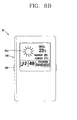
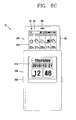
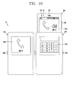
- FIGS. 8 to 10 are conceptual views showing various User Interfaces (Uls) based on a received state of the terminal body shown in FIG. 2A in the pouch 200.
- the display unit 151 may output visual information of a first mode.
- the display unit 151 may output icons, such as weather, time, current weather, execution of a specific application and the like, in the first mode.
- the terminal body 100 When the terminal body 100 is received in the pouch 200 and the first connection port 171 and the second connection port 271 are electrically connected to each other, visual information of a second mode may be output on a portion 151 a of the display unit 151 exposed through the opening 211a.
- the terminal body 100 may include a proximity sensor 141 for sensing whether or not an external object is proximate.
- the proximity sensor 141 may be disposed to overlap the pouch 200 in the pouch state.
- the display unit 151 may output visual information of the pouch mode when the proximity sensor 141 senses the proximity of the external object in the second mode, and output visual information of the half pouch mode when the proximity sensor 141 has not sensed the proximity of the external object.
- the portion 151a exposed through the opening 211a may display brief information related to current states, such as weather, time, current weather and the like.
- different visual information may be output separately on a portion 151b of the display unit 151 exposed through the opening 211a of the pouch 200 and an externally exposed portion 151c.
- the portion 151b exposed through the opening 211a may output brief information related to the current states
- the externally exposed portion 151c may output information related to specific information (e.g., weather) indicating the current state, such as a weakly weather.
- the camera 121' mounted onto the rear surface of the terminal body 100 when the camera 121' mounted onto the rear surface of the terminal body 100 operates in the pouch state, upon conversion into the half pouch state, the camera 121 mounted onto the front surface of the terminal body 100 may operate.
- the portion 151b of the display unit 151 exposed through the opening 211 a of the pouch 200 may output menus (sub menus) for setting brightness, zoom-in/zoom-out, white balance (WB) and the like, all associated with capturing (main menu), and the externally exposed portion 151c may display an image screen to be captured by the camera 121.
- menus sub menus
- WB white balance
- the terminal body 100 may be set to be converted into a phone call mode using an audio output module 152' (speaker).
- the portion 151b of the display unit 151 exposed through the opening 211 a may display user setting applications, such as a memo application, a schedule application, a calculator application and the like, performing other tasks during a phone call.
- the slide unit may support the terminal body, be relatively slidable with respect to the base through the guide unit, and be locked/unlocked at a preset position of the base through the locking unit. Therefore, the terminal body may be received in a pouch state that it is received in the base and in a half pouch state that at least part thereof is exposed.
- the terminal body may sense a received state in the pouch by use of a connection port, a proximity sensor and the like to perform a specific function according to each sensed state and have an extended wireless communication function through sub antennas disposed in the pouch. This may result in providing a mobile terminal having a more extended function.
Description
- This specification relates to a pouch and a mobile terminal having a main body capable of being received (accommodated) in the pouch.
- Mobile terminals are electronic devices which are portable and have at least one of voice and telephone call functions, information input and/or output functions, a data storage function and the like.
- As it becomes multifunctional, the mobile terminal can be allowed to capture still images or moving images, play music or video files, play games, receive broadcast and the like, so as to be implemented as an integrated multimedia player.
- Various attempts have been done for the multimedia device in aspect of hardware or software in order to implement such complicated functions. Among those attempts, improvement of the hardware configuration may be considered.
- As the mobile terminals are regarded as personal belongings to express personalities, various design factors are required. Such design factors include structural changes and improvement for making an appearance of the mobile terminal better.
- The mobile terminals are affected by external environments, such as moisture, dust, impact and the like during usage. This leads to production of cases, pouches and the like having a function of making the appearance of the mobile terminal more attractive as well as a function of simply protecting the mobile terminal from the external environments. As one example of the structural changes and improvement, a pouch and a mobile terminal having a terminal body capable of being received within the pouch may be regarded. Examples and possible embodiments are disclosed in documents
US 2009/135555 A1 andUS 2009/154082 A1 . - Therefore, an aspect of the detailed description is to provide a pouch capable of receiving a terminal body in various states.
- Another aspect of the detailed description is to provide a mobile terminal capable of giving various functions to a terminal body or extending conventional functions by use of the pouch.
- To achieve these and other advantages and in accordance with the purpose of this specification, as embodied and broadly described herein, there is provided a pouch for a mobile terminal including a base defining a space for receiving at least part of a terminal body therein, a slide unit disposed within the base, and relatively slidable with respect to the base along a lengthwise direction of the terminal body, the slide unit supporting the terminal body, an elastic unit disposed between the base and the slide unit to apply an elastic force, a guide unit configured to guide the relative sliding of the slide unit, and a locking unit configured to lock and unlock the slide unit at and from a preset position of the base.
- In accordance with one aspect, the slide unit may be slidable between a first state in which the terminal body is received in the base and a second state in which at least part of the terminal body is exposed.
- In accordance with another aspect, the base may include a frame disposed to obscure both side surfaces of the terminal body, and a fixed plate connected to the frame and disposed to obscure a rear surface of the terminal body.
- The slide unit may include a moving plate disposed to obscure the rear surface of the terminal body, and relatively slidable with facing the fixed plate, and a support plate extending from the moving plate, and protruding from the moving plate to support the terminal body.
- Also, the guide unit may include a first guide rail formed through the fixed plate and extending in one direction, a second guide rail formed through the moving plate and extending in an intersecting direction with the one direction, and a guide member inserted into the first and second guide rails and movable in response to the sliding of the slide unit.
- The guide member may include a body inserted into the first and second guide rails, and protruding portions protruding along an outer circumferential surface of the body to obscure the fixed plate and the moving plate, respectively.
- Also, the first guide rail may be internally inclined with respect to the sliding direction of the slide unit.
- The locking unit may include a first guide rail extending portion extending from the first guide rail in the intersecting direction with the one direction, so as to receive the guide member therein such that the slide unit is fixed to a preset position, and a manipulation portion mounted onto the fixed plate to press the guide member to be placed on the first guide rail.
- The manipulation portion may be disposed adjacent to the first guide rail extending portion, and formed to be movable in one direction so as to press the guide member.
- The elastic unit may include a first elastic member configured to apply an elastic force to the slide unit in the sliding direction of the slide unit, and a second elastic member configured to apply an elastic force to the guide member in the intersecting direction with the sliding direction such that the guide member is received in the first guide rail extending portion.
- Also, the second elastic member may be a spring having one end fixed to the moving plate and the other end fixed to the guide member.
- To achieve the above aspects, there is provided a mobile terminal including a terminal body having a display unit on a front surface and configured to perform a wireless communication function, and the above pouch for the mobile terminal, the pouch configured to receive the terminal body therein and having an opening for exposing at least part of the display unit.
- The terminal body may include a first connection port, and the first connection port may be electrically connected to a second connection port mounted onto a bottom surface of the base.
- The display unit may be configured to output visual information of a first mode in a state that the terminal body is separated from the pouch for the mobile terminal, while outputting visual information of a second mode when the first connection port and the second connection port are electrically connected to each other.
- The terminal body may further include a proximity sensor disposed to overlap the pouch for the mobile terminal in the first state, and configured to sense whether or not an external object is proximate. The display unit may output visual information of a pouch mode when the proximity sensor senses the proximity of the external object, and output visual information of a half pouch mode when the proximity sensor has not sensed the proximity of the external object.
- The display unit may be configured to output a main menu in the pouch mode, and to output sub menus of the main menu in the half pouch mode.
- First and second cameras may be mounted onto a rear surface and a front surface of the terminal body, respectively. The terminal body may be converted into an operating mode of the second camera, upon conversion into the second state, while operating in an operating mode of the first camera in the first state.
- The terminal body may be converted into an operating mode of a speakerphone upon conversion into the second state while operating in a phone call mode in the first state.
- In accordance with another aspect, the terminal body may include a main antenna configured to transmit and receive a wireless signal, and the pouch for the mobile terminal may include sub antennas installed therein to extend the wireless communication function of the terminal body.
- The sub antennas may be disposed adjacent to the main antenna with preset intervals so as to form coupling with the main antenna.
- Further scope of applicability of the present application will become more apparent from the detailed description given hereinafter. However, it should be understood that the detailed description and specific examples, while indicating preferred embodiments of the invention, are given by way of illustration only, since various changes and modifications within the spirit and scope of the invention will become apparent to those skilled in the art from the detailed description.
- The accompanying drawings, which are included to provide a further understanding of the invention and are incorporated in and constitute a part of this specification, illustrate exemplary embodiments and together with the description serve to explain the principles of the invention.
- In the drawings:
-
FIG. 1 is a block diagram of a mobile terminal in accordance with one exemplary embodiment; -
FIG. 2A illustrates one example of the mobile terminal according to this specification, which is a front perspective view showing a separated state of a terminal body from a pouch; -
FIG. 2B is a perspective view showing a received state of the terminal body shown inFIG. 2A in the pouch (i.e., a half pouch state); -
FIG. 2C is a rear perspective view showing the separated state of the terminal body shown inFIG. 2A from the pouch; -
FIG. 3 is a front conceptual view of the pouch, taken along the line III-III ofFIG. 2A ; -
FIG. 4 is a sectional view taken along the line IV-IV ofFIG. 3 ; -
FIGS. 5A and5B are conceptual views showing an operating mechanism of the pouch shown inFIG. 3 ; -
FIG. 6 is a conceptual view showing connection ports for electrically connecting the terminal body to the pouch shown inFIG. 2A ; -
FIG. 7 is a conceptual view showing an antenna for extending a wireless communication function of the terminal body and the pouch shown inFIG. 2A ; and -
FIGS. 8 to 10 are conceptual views showing various User Interfaces (Uls) based on a received state of the terminal body in the pouch, shown inFIG. 2A . - Description will now be given in detail of a pouch and a mobile terminal having the same according to the exemplary embodiments, with reference to the accompanying drawings.
- For the sake of brief description with reference to the drawings, the same or equivalent components will be provided with the same reference numbers, and description thereof will not be repeated. The expression in the singular form in this specification will cover the expression in the plural form unless otherwise indicated obviously from the context.
- Hereinafter, suffixes "module" and "unit or portion" for components used herein in description are merely provided only for facilitation of preparing this specification, and thus they are not granted a specific meaning or function.
- Mobile terminals described in this specification may include cellular phones, smart phones, laptop computers, digital broadcasting terminals, personal digital assistants (PDAs), portable multimedia players (PMPs), E-books, navigators, and the like.
-
FIG. 1 is a block diagram of amobile terminal 10 in accordance with one exemplary embodiment. - The
mobile terminal 10 may comprise components, such as awireless communication unit 110, an Audio/Video (A/V)input unit 120, auser input unit 130, asensing unit 140, anoutput unit 150, amemory 160, aninterface unit 170, acontroller 180, apower supply 190 and the like.FIG. 1 shows themobile terminal 10 having various components, but it is understood that implementing all of the illustrated components is not a requirement. Greater or fewer components may alternatively be implemented. - Hereinafter, each component is described in sequence.
- The
wireless communication unit 110 may typically include one or more modules which permit wireless communications between themobile terminal 10 and a wireless communication system or between themobile terminal 10 and a network within which themobile terminal 10 is located. For example, thewireless communication unit 110 may include abroadcast receiving module 111, amobile communication module 112, awireless Internet module 113, a short-range communication module 114, alocation information module 115 and the like. - The
broadcast receiving module 111 receives a broadcast signal and/or broadcast associated information from an external broadcast managing entity via a broadcast channel. - The broadcast channel may include a satellite channel and a terrestrial channel. The broadcast managing entity may indicate a server which generates and transmits a broadcast signal and/or broadcast associated information or a server which receives a pre-generated broadcast signal and/or broadcast associated information and sends them to the mobile terminal. The broadcast signal may be implemented as a TV broadcast signal, a radio broadcast signal, and a data broadcast signal, among others. The broadcast signal may further include a data broadcast signal combined with a TV or radio broadcast signal.
- Examples of broadcast associated information may include information associated with a broadcast channel, a broadcast program, a broadcast service provider, and the like. The broadcast associated information may be provided via a mobile communication network, and received by the
mobile communication module 112. - The broadcast associated information may be implemented in various formats. For instance, broadcast associated information may include Electronic Program Guide (EPG) of Digital Multimedia Broadcasting (DMB), Electronic Service Guide (ESG) of Digital Video Broadcast-Handheld (DVB-H), and the like.
- The
broadcast receiving module 111 may be configured to receive digital broadcast signals transmitted from various types of broadcast systems. Such broadcast systems may include Digital Multimedia Broadcasting-Terrestrial (DMB-T), Digital Multimedia Broadcasting-Satellite (DMB-S), Media Forward Link Only (MediaFLO), Digital Video Broadcast-Handheld (DVB-H), Integrated Services Digital Broadcast-Terrestrial (ISDB-T) and the like. Thebroadcast receiving module 111 may be configured to be suitable for every broadcast system transmitting broadcast signals as well as the digital broadcasting systems. - Broadcast signals and/or broadcast associated information received via the
broadcast receiving module 111 may be stored in a suitable device, such as amemory 160. - The
mobile communication module 112 transmits/receives wireless signals to/from at least one of network entities (e.g., base station, an external mobile terminal, a server, etc.) on a mobile communication network. Here, the wireless signals may include audio call signal, video (telephony) call signal, or various formats of data according to transmission/reception of text/multimedia messages. - The
wireless Internet module 113 supports wireless Internet access for the mobile terminal. This module may be internally or externally coupled to themobile terminal 10. Examples of such wireless Internet access may include Wireless LAN (WLAN) (Wi-Fi), Wireless Broadband (Wibro), Worldwide Interoperability for Microwave Access (Wimax), High Speed Downlink Packet Access (HSDPA) and the like. - The short-
range communication module 114 denotes a module for short-range communications. Suitable technologies for implementing this module may include BLUETOOTH™, Radio Frequency IDentification (RFID), Infrared Data Association (IrDA), Ultra-WideBand (UWB), ZigBee™, and the like. - The
location information module 115 denotes a module for detecting or calculating a position of a mobile terminal. An example of thelocation information module 115 may include a Global Position System (GPS) module. - Referring to
FIG. 1 , the ANinput unit 120 is configured to provide audio or video signal input to the mobile terminal. The ANinput unit 120 may include acamera 121 and amicrophone 122. Thecamera 121 receives and processes image frames of still pictures or video obtained by image sensors in a video call mode or a capturing mode. The processed image frames may be displayed on adisplay unit 151. - The image frames processed by the
camera 121 may be stored in thememory 160 or transmitted to the exterior via thewireless communication unit 110. Two ormore cameras 121 may be provided according to the configuration of the mobile terminal. - The
microphone 122 may receive an external audio signal while the mobile terminal is in a particular mode, such as a phone call mode, a recording mode, a voice recognition mode, or the like. This audio signal is processed into digital data. The processed digital data is converted for output into a format transmittable to a mobile communication base station via themobile communication module 112 in case of the phone call mode. Themicrophone 122 may include assorted noise removing algorithms to remove noise generated in the course of receiving the external audio signal. - The
user input unit 130 may generate input data input by a user to control the operation of the mobile terminal. Theuser input unit 130 may include a keypad, a dome switch, a touchpad (e.g., static pressure/capacitance), a jog wheel, a jog switch and the like. - The
sensing unit 140 provides status measurements of various aspects of the mobile terminal. For instance, thesensing unit 140 may detect an open/close status of the mobile terminal, a change in a location of themobile terminal 10, a presence or absence of user contact with themobile terminal 10, the location of themobile terminal 10, acceleration/deceleration of themobile terminal 10, and the like, so as to generate a sensing signal for controlling the operation of themobile terminal 10. For example, regarding a slide-type mobile terminal, thesensing unit 140 may sense whether a sliding portion of the mobile terminal is open or closed. Other examples include sensing functions, such as thesensing unit 140 sensing the presence or absence of power provided by thepower supply 190, the presence or absence of a coupling or other connection between theinterface unit 170 and an external device. Meanwhile, thesensing unit 140 may include aproximity sensor 141. - The
output unit 150 is configured to output an audio signal, a video signal or a tactile signal. Theoutput unit 150 may include adisplay unit 151, anaudio output module 152, analarm unit 153 and ahaptic module 154. - The
display unit 151 may output information processed in themobile terminal 10. For example, when the mobile terminal is operating in a phone call mode, thedisplay unit 151 will provide a User Interface (UI) or a Graphic User Interface (GUI), which includes information associated with the call. As another example, if the mobile terminal is in a video call mode or a capturing mode, thedisplay unit 151 may additionally or alternatively display images captured and/or received, UI, or GUI. - The
display unit 151 may be implemented using, for example, at least one of a Liquid Crystal Display (LCD), a Thin Film Transistor-Liquid Crystal Display (TFT-LCD), an Organic Light-Emitting Diode (OLED), a flexible display, a three-dimensional (3D) display, or the like. - Some of
such displays 151 may be implemented as a transparent type or an optical transparent type through which the exterior is visible, which is referred to as 'transparent display'. A representative example of the transparent display may include a Transparent OLED (TOLED), and the like. The rear surface of thedisplay unit 151 may also be implemented to be optically transparent. Under this configuration, a user can view an object positioned at a rear side of a terminal body through a region occupied by thedisplay unit 151 of the terminal body. - The
display unit 151 may be implemented in two or more in number according to a configured aspect of themobile terminal 10. For instance, a plurality of thedisplays 151 may be arranged on one surface to be spaced apart from or integrated with each other, or may be arranged on different surfaces. - Here, if the
display unit 151 and a touch sensitive sensor (referred to as a touch sensor) have a layered structure therebetween, the structure may be referred to as a touch screen. Thedisplay unit 151 may be used as an input device rather than an output device. The touch sensor may be implemented as a touch film, a touch sheet, a touch pad, and the like. - The touch sensor may be configured to convert changes of a pressure applied to a specific part of the
display unit 151, or a capacitance occurring from a specific part of thedisplay unit 151, into electric input signals. Also, the touch sensor may be configured to sense not only a touched position and a touched area, but also a touch pressure. - When touch inputs are sensed by the touch sensors, corresponding signals are transmitted to a touch controller (not shown). The touch controller processes the received signals, and then transmits corresponding data to the
controller 180. Accordingly, thecontroller 180 may sense which region of thedisplay unit 151 has been touched. - Still referring to
FIG. 1 , aproximity sensor 141 may be arranged at an inner region of themobile terminal 10 covered by the touch screen, or near the touch screen. Theproximity sensor 141 indicates a sensor to sense presence or absence of an object approaching to a surface to be sensed, or an object disposed near a surface to be sensed, by using an electromagnetic field or infrared rays without a mechanical contact. Theproximity sensor 141 has a longer lifespan and a more enhanced utility than a contact sensor. - The
proximity sensor 141 may include a transmissive type photoelectric sensor, a direct reflective type photoelectric sensor, a mirror reflective type photoelectric sensor, a high-frequency oscillation proximity sensor, a capacitance type proximity sensor, a magnetic type proximity sensor, an infrared rays proximity sensor, and so on. When the touch screen is implemented as a capacitance type, proximity of a pointer to the touch screen is sensed by changes of an electromagnetic field. In this case, the touch screen (touch sensor) may be categorized into a proximity sensor. - Hereinafter, for the sake of brief explanation, a status that the pointer is positioned to be proximate onto the touch screen without contact will be referred to as 'proximity touch', whereas a status that the pointer substantially comes in contact with the touch screen will be referred to as 'contact touch'. For the position corresponding to the proximity touch of the pointer on the touch screen, such position corresponds to a position where the pointer faces perpendicular to the touch screen upon the proximity touch of the pointer.
- The
proximity sensor 141 senses proximity touch, and proximity touch patterns (e.g., distance, direction, speed, time, position, moving status, etc.). Information relating to the sensed proximity touch and the sensed proximity touch patterns may be output onto the touch screen. - The
audio output module 152 may output audio data received from thewireless communication unit 110 or stored in thememory 160, in a call-receiving mode, a call-placing mode, a recording mode, a voice recognition mode, a broadcast reception mode, and so on. Theaudio output module 152 may output audio signals relating to functions performed in themobile terminal 10, e.g., sound alarming a call received or a message received, and so on. Theaudio output module 152 may include a receiver, a speaker, a buzzer, and so on. - The
alarm unit 153 outputs signals notifying occurrence of events from themobile terminal 10. The events occurring from themobile terminal 10 may include call received, message received, key signal input, touch input, and so on. Thealarm unit 153 may output not only video or audio signals, but also other types of signals such as signals notifying occurrence of events in a vibration manner. Since the video or audio signals can be output through thedisplay unit 151 or theaudio output module 152, thedisplay unit 151 and theaudio output module 152 may be categorized into a part of thealarm unit 153. - The
haptic module 154 generates various tactile effects which a user can feel. A representative example of the tactile effects generated by thehaptic module 154 includes vibration. Vibration generated by thehaptic module 154 may have a controllable intensity, a controllable pattern, and so on. For instance, different vibration may be output in a synthesized manner or in a sequential manner. - The
haptic module 154 may generate various tactile effects, including not only vibration, but also arrangement of pins vertically moving with respect to a skin being touched (contacted), air injection force or air suction force through an injection hole or a suction hole, touch by a skin surface, presence or absence of contact with an electrode, effects by stimulus such as an electrostatic force, reproduction of cold or hot feeling using a heat absorbing device or a heat emitting device, and the like. - The
haptic module 154 may be configured to transmit tactile effects (signals) through a user's direct contact, or a user's muscular sense using a finger or a hand. Thehaptic module 154 may be implemented in two or more in number according to the configuration of themobile terminal 10. - The
memory 160 may store a program for the processing and control of thecontroller 180. Alternatively, thememory 160 may temporarily store input/output data (e.g., phonebook data, messages, still images, video and the like). Also, thememory 160 may store data related to various patterns of vibrations and audio output upon the touch input on the touch screen. - The
memory 160 may be implemented using any type of suitable storage medium including a flash memory type, a hard disk type, a memory card type (e.g., SD or DX memory), Random Access Memory (RAM), Static Random Access Memory (SRAM), Read-Only Memory (ROM), Electrically Erasable Programmable Read-Only Memory (EEPROM), Programmable Read-Only Memory (PROM), magnetic memory, magnetic disk, optical disk, and the like. Also, themobile terminal 10 may operate a web storage which performs the storage function of thememory 160 on the Internet. - The
interface unit 170 may generally be implemented to interface the mobile terminal with external devices. Theinterface unit 170 may allow a data reception from an external device, a power delivery to each component in themobile terminal 10, or a data transmission from themobile terminal 10 to an external device. Theinterface unit 170 may include, for example, wired/wireless headset ports, external charger ports, wired/wireless data ports, memory card ports, ports for coupling devices having an identification module, audio Input/Output (I/O) ports, video I/O ports, earphone ports, and the like. - The identification module may be configured as a chip for storing various information required to authenticate an authority to use the
mobile terminal 10, which may include a User Identity Module (UIM), a Subscriber Identity Module (SIM), and the like. Also, the device having the identification module (hereinafter, referred to as 'identification device') may be implemented in a type of smart card. Hence, the identification device can be coupled to themobile terminal 10 via a port. - Also, the
interface unit 170 may serve as a path for power to be supplied from an external cradle to themobile terminal 10 when themobile terminal 10 is connected to the external cradle or as a path for transferring various command signals input from the cradle by a user to themobile terminal 10. Such various command signals or power input from the cradle may operate as signals for recognizing that themobile terminal 10 has accurately been mounted to the cradle. - The
controller 180 typically controls the overall operations of themobile terminal 10. For example, thecontroller 180 performs the control and processing associated with telephony calls, data communications, video calls, and the like. Thecontroller 180 may include amultimedia module 181 which provides multimedia playback. Themultimedia module 181 may be configured as part of thecontroller 180 or as a separate component. - The
controller 180 can perform a pattern recognition processing so as to recognize writing or drawing input on the touch screen as text or image. - The
power supply 190 provides power required by various components under the control of thecontroller 180. The provided power may be internal power, external power, or combination thereof. - Various embodiments described herein may be implemented in a computer-readable medium using, for example, software, hardware, or some combination thereof.
- For a hardware implementation, the embodiments described herein may be implemented within one or more Application Specific Integrated Circuits (ASICs), Digital Signal Processors (DSPs), Digital Signal Processing Devices (DSPDs), Programmable Logic Devices (PLDs), Field Programmable Gate Arrays (FPGAs), processors, microprocessors, other electronic units designed to perform the functions described herein, or a selective combination thereof. In some cases, such embodiments are implemented by the
controller 180. - For software implementation, the embodiments such as procedures and functions may be implemented together with separate software modules each of which performs at least one of functions and operations. The software codes can be implemented with a software application written in any suitable programming language. Also, the software codes may be stored in the
memory 160 and executed by thecontroller 180. -
FIG. 2A illustrates one example of themobile terminal 10 according to this specification, which is a front perspective view showing a separated state of aterminal body 100 from apouch 200. - The
mobile terminal 10 may include aterminal body 100 and apouch 200 for receiving (accommodating) theterminal body 100 therein. Theterminal body 100 may perform a wireless communication function and be configured to be received in or separated from thepouch 200. Thepouch 200 may serve to protect the mobile terminal 10 from external environments and give attraction to themobile terminal 10. Thepouch 200 may include anopening 211a corresponding to thedisplay unit 151 such that thedisplay unit 151 can be partially exposed when theterminal body 100 is received in thepouch 200. A detailed structure of thepouch 200 will be explained later with reference toFIG. 3 . - The
mobile terminal 10 includes a bartype terminal body 100. However, this detailed description may be applicable, but not limited to, a various structures, such as a slide type, a folder type, a swing type, a swivel type and the like, having two or more bodies coupled to be relatively movable with each other. - A body may include a case (or referred to as casing, housing, cover, etc.) defining an appearance of the
mobile terminal 10. In this exemplary embodiment, the case may be divided into afront case 101 and arear case 102. A space formed between the front andrear cases rear cases - Such cases may be injected using a synthetic resin or be formed of a metal, such as stainless steel (STS), titanium (Ti) or the like.
- The terminal body is shown having a
display unit 151, anaudio output module 152, acamera 121, auser input unit 130/131, 132, amicrophone 122, aninterface unit 170, and the like. - The
display unit 151 may occupy most of a principal surface of thefront case 101. Theaudio output module 152 and thecamera 121 may be disposed near one of both end portions of thedisplay unit 151, and theuser input unit 131 and themicrophone 122 on the other end portion of thedisplay unit 151. Theuser input unit 132, theinterface unit 170 and the like may be disposed on side surfaces of the front andrear cases - The
user input unit 130 may be manipulated to allow inputting of commands for controlling operations of themobile terminal 10, and include a plurality offirst manipulation units manipulation units - The first and
second manipulation units first manipulation unit 131 may be configured to input commands such as START, END, SCROLL or the like, and thesecond manipulation unit 132 may be configured to input commands, such as a volume adjustment of sounds output from theaudio output module 152, conversion of thedisplay unit 151 into a touch recognition mode, or the like. -
FIG. 2B is a perspective view showing a received state of theterminal body 100 shown inFIG. 2A in the pouch 200 (i.e., a half pouch state). - The
terminal body 100 may be completely received in the pouch 200 (i.e., a pouch state, first state) or partially exposed according to an operating mechanism of the pouch 200 (i.e., a half pouch state, second state). - The
terminal body 100 may perform a specific function according to the received state in thepouch 200, and achieve a more extended function using thepouch 200. It may also be natural that theterminal body 100 can independently operate with being completely separated from thepouch 200. -
FIG. 2C is a rear perspective view showing the separated state of theterminal body 100 shown inFIG. 2A from thepouch 200. - Referring to
FIG. 2C , a rear face of the terminal body, namely, therear case 102 may further be provided with a camera 121'. The camera 121' faces a direction which is opposite to a direction faced by the camera 121 (seeFIG. 2A ), and may have different pixels from those of thecamera 121. - For example, the
camera 121 may operate with relatively lower pixels (lower resolution). Thus, thecamera 121 may be useful when a user can capture his face and send it to another party during a video call or the like. On the other hand, the camera 121' may operate with a relatively higher pixels (higher resolution) such that it can be useful for a user to obtain higher quality pictures for later use. Thecameras 121 and 121' may be installed in the terminal body to be rotatable or popped up. - A
flash 123 and amirror 124 may additionally be disposed adjacent to the camera 121'. Theflash 123 operates in conjunction with the camera 121' when taking a picture using the camera 121'. Themirror 124 can cooperate with the camera 121' to allow a user to photograph himself in a self-portrait mode. - An audio output module 152' may further be disposed at a rear face of the terminal body. The audio output module 152' can cooperate with the audio output module 152 (see
FIG. 2A ) to provide stereo output. Also, the audio output module 152' may be configured to operate as a speakerphone. - A broadcast signal receiving antenna (not shown) may further be disposed at one side of the terminal body in addition to an antenna for communications, for example. The
antenna 124 configuring a part of the broadcast receiving module 111 (seeFIG. 1 ) may be retractable into the terminal body. - A
power supply unit 190 for supplying power to themobile terminal 10 may be mounted in the terminal body. Thepower supply unit 190 may be mounted in theterminal body 100 or detachably coupled directly onto the outside of theterminal body 100. -
FIG. 3 is a front conceptual view of the pouch, taken along the line III-III ofFIG. 2A , andFIG. 4 is a sectional view taken along the line IV-IV ofFIG. 3 . - As shown in
FIGS. 3 and4 , thepouch 200 may have a structure of receiving (accommodating) theterminal body 100 in a pouch state and in a half pouch state, and converting one state into another state according to a manipulation. Thepouch 200 may include abase 210, aslide unit 220, anelastic unit 230, aguide unit 240, and alocking unit 260. - The base 210 may form a space for receiving at least part of the
terminal body 100. The base 210 may include anopening 210a for allowing theterminal body 100 to be inserted thereinto in one direction. This exemplary embodiment illustrates that theopening 210a is formed at an upper end of the base 210 such that theterminal body 100 can be inserted in a lengthwise direction. - The base 210 may also include a
frame 211 and afixed plate 212. Theframe 211 may cover both side surfaces of theterminal body 100, and include anopening 211 a (seeFIG. 2A ), which is formed at a front surface thereof and corresponds to thedisplay unit 151 to expose at least part of thedisplay unit 151. The fixedplate 212 may be connected to theframe 211 and cover a rear surface of theterminal body 100. Theframe 211 and the fixedplate 212 may be integrally formed with each other. - The base 210 may also include a cover 213 (see
FIG. 2A ) defining an appearance thereof. Thecover 213 may shield theframe 211 and the fixedplate 212, and obtain esthetic appreciation through surface processing. Thecover 213 may be formed of leather or synthetic resin, or of a metal such as stainless steel (STS), aluminum (Al), titanium (Ti) or the like. - The
slide unit 220 may be disposed within thebase 210. Theslide unit 220 may support theterminal body 100, and be coupled to be relatively slidable with respect to the base 210 in a lengthwise direction of theterminal body 100. - In detail, the
slide unit 220 may include a movingplate 221, and asupport plate 222. The movingplate 221 may shield a rear surface of theterminal body 100, and be relatively slidable with facing the fixedplate 212. Thesupport plate 222 may extend from the movingplate 221, and protrude from the movingplate 221 to support theterminal body 100. The movingplate 221 and thesupport plate 222 may be integrally formed with each other. - The
guide unit 240 may be configured to guide relative sliding of theslide unit 220 with respect to thebase 210. Theguide unit 240 may include afirst guide rail 241, asecond guide rail 242, and aguide member 243. - The
first guide rail 241 may penetrate through the fixedplate 212, and extend in one direction. Thefirst guide rail 241 may extend in a relative sliding direction of theslide unit 220, namely, in the lengthwise direction of theterminal body 100, or formed to be internally or externally inclined from the relative sliding direction. - The
second guide rail 242 may penetrate through the movingplate 221, and extend along an intersecting direction with the one direction. This exemplary embodiment illustrates that thefirst guide rail 241 is internally inclined from the relative sliding direction and thesecond guide rail 242 extends toward the inside. - The first and
second guide rails guide member 243 may be inserted into the overlapped portion. Theguide member 243 may be movable in response to the sliding of theslide unit 220. In detail, when theslide unit 220 is slid by an external force in one direction, theguide member 243 which is brought into contact with theslide unit 220 moves along thefirst guide rail 241. Theslide unit 220 may accordingly be slid along a preset path. - The
guide member 243 may have a structure of prevented from being separated from the first andsecond guide rails guide member 243 may include abody 243a, and protrudingportions body 243a. Thebody 243a may be inserted into the first andsecond guide rails portions body 243a, and obscure thefixed plate 212 and the movingplate 221, respectively. - At least one
guide unit 240 may be provided at at least one side of thepouch 200. As shown, theguide unit 240 may be disposed adjacent to both sides of thepouch 200. For more stable operations, aguide unit 250 having the same shape as theguide unit 240 may further be disposed. - The
locking unit 260 may be configured to lock or unlock theslide unit 220 at or from a preset position of thebase 210. Thelocking unit 260 may include a first guiderail extending portion 261 and amanipulation portion 262. - The first guide
rail extending portion 261 may extend from thefirst guide rail 241 along a direction intersecting with the one direction. As shown in the drawings, the first guiderail extending portion 261 may externally extend with respect to the relative sliding direction. Theguide member 243 may be accommodated in the first guiderail extending portion 261 to fix theslide unit 220 to a preset position. - The
manipulation portion 262 may be formed at the fixedplate 212 to be pressed in one direction. As one end of themanipulation portion 262 pushes theguide member 243 by being pressed, theguide member 243 may be disposed on thefirst guide rail 241. In detail, themanipulation portion 262 may be disposed adjacent to the first guiderail extending portion 261, and mounted to be movable in one direction so as to press theguide member 243. - The
manipulation portion 262 may include a throughhole 263 for insertion of apin 265 therein, and the fixedplate 212 may include ahole 264 extending in one direction such that thepin 265 is movably inserted therein. The one direction may be a direction toward the first guiderail extending portion 261. One end of themanipulation portion 262 may be disposed to overlap the first guiderail extending portion 261, thus being pushed away by theguide member 243 when theguide member 243 is inserted into the first guiderail extending portion 261. Thepin 265 may have the same shape as that of theguide member 243. - The
elastic unit 230 may be disposed between the base 210 and theslide unit 220 to apply an elastic force. Theelastic unit 230 may include a firstelastic member 231 and a secondelastic member 232. - The first
elastic member 231 may apply the elastic force to theslide unit 220 in a sliding direction of theslide unit 220. The firstelastic member 231 may be disposed adjacent to a central axis of thepouch 200 to prevent the elastic force from being concentrated onto one side. Both ends of the firstelastic member 231 may be fixed to the fixedplate 212 and the movingplate 221, respectively. - The second
elastic member 232 may apply the elastic force to theguide member 243 in a direction intersecting with the sliding direction such that theguide member 243 can be received in the first guiderail extending portion 261. The secondelastic member 232 may be implemented as a spring whose one end is fixed to the movingplate 221 and the other end is fixed to theguide member 243. -
FIGS. 5A and5B are conceptual views showing an operating mechanism of thepouch 200 shown inFIG. 3 . The drawings omit theterminal body 100 for the sake of explanation, but it may be understood that theterminal body 100 is supported by thesupport plate 222.FIG. 3 shows the half pouch state that theterminal body 100 is partially inserted, andFIGS. 5A and5B show the pouch state that theterminal body 100 is completely inserted, namely, locked and unlocked states. - The
slide unit 220 may be slidable between a first state (pouch state) that theterminal body 100 is received in thebase 210 and a second state (half pouch state) that at least part of theterminal body 100 is exposed. - Referring to
FIG. 3 , theslide unit 220 may be located adjacent to an upper end of the base 210 by the firstelastic member 231. Theguide member 243 may receive the elastic force from the secondelastic member 232 applied to the outside of thepouch 200. Thesupport plate 222 may be disposed adjacent to a middle portion of thepouch 200, and theterminal body 100 may be in the half pouch state that at least part of theterminal body 100 is exposed when theterminal body 100 is inserted. - Referring to
FIGS. 5A and5B , theslide unit 220 may be relatively slid on one surface of the base 210 in response to an external force (i.e., a force that theterminal body 100 presses the support plate 222). Theguide member 243 may guide sliding of theslide unit 220 while moving along the first andsecond guide rails first guide rail 241 is formed to be inclined with respect to the sliding direction, theguide member 243 may move in a contact state with a surface forming thefirst guide rail 241. Consequently, theslide unit 220 may be slidable at an appropriate speed, and be free from an impact upon a conversion into the half pouch state. - The
guide member 243 is receiving the elastic force applied toward the outside by the secondelastic member 232. Accordingly, when theguide member 243 reaches the first guiderail extending portion 261, it may be received in the first guiderail extending portion 261 so as to fix theslide unit 220 to a preset position. One end of themanipulation portion 262 may overlap the first guiderail extending portion 261, and accordingly be pushed away by theguide member 243 when theguide member 243 is inserted into the first guiderail extending portion 261.FIG. 5A shows a state that themanipulation portion 262 has protruded from theframe 211 due to being pressed by theguide member 243. - When the
manipulation portion 262 is pressed in the locked state, themanipulation portion 262 presses theguide member 243. Theguide member 243 is then pushed away from the first guiderail extending portion 261 to be placed on thefirst guide rail 241. As the locked state is released, theslide unit 220 is slid toward the upper end of the base 210 by an elastic restoring force of the firstelastic member 231. - The
slide unit 220 may be relatively slid with respect to thebase 210 by the mechanism, and theterminal body 100 may be received in thepouch 200 in the pouch state and in the half pouch state. -
FIG. 6 is a conceptual view showing connection ports for electrical connection between theterminal body 100 and thepouch 200 shown inFIG. 2A . - The
terminal body 100 may include afirst connection port 171 and thepouch 200 may include asecond connection port 271 for electrical connection to thefirst connection port 171. Thesecond connection port 271 may include a plurality of terminals. The plurality of terminals may include an anode (+) terminal, a cathode (-) terminal, and a ground terminal. - Referring to
FIG. 6 , a plurality of terminals configuring thefirst connection port 171 may be disposed at a lower portion of theterminal body 100. The plurality of terminals may receive power supplied from the exterior. Thesecond connection port 271 may be mounted onto a bottom surface of the base 210 or onto thesupport plate 222, and contactable with theterminal body 100 when theterminal body 100 is inserted. Thesecond connection port 271 may elastically press thefirst connection port 171 to maintain the contact state with thefirst connection port 171 upon an external impact being applied. - The
second connection port 271 may be externally exposed so as to contact a terminal of an external device (for example, a cradle, a docking station, etc.). Theterminal body 100 may be electrically connected to the external device so as to receive power supply or transmit or receive data. - When the
first connection port 171 is electrically connected to thesecond connection port 271, thecontroller 180 of theterminal body 100 may sense the electrical connection so as to perform a specific function. For example, thedisplay unit 151 may output visual information of a first mode in a state that theterminal body 100 is separated from thepouch 200, and output visual information of a second mode when thefirst connection port 171 is electrically connected to thesecond connection port 271. -
FIG. 7 is a conceptual view showing an antenna for extending wireless communication functions of theterminal body 100 and thepouch 200 shown inFIG. 2A . - The
terminal body 100 may include amain antenna 110a for transmission and reception of a wireless signal. For example, themain antenna 110a may be at least one of an antenna formed to transmit and receive a wireless signal corresponding to at least one of Personal Communication System (PCS), Advanced Wireless Service (AWS), Digital Communications Network (DCN) and Long Term Evolution (LTE), a broadcast signal receiving antenna operating at an FM radio frequency band, a short-range wireless communication antenna such as Bluetooth (BT) and Wi-Fi, and a satellite signal receiving antenna. -
Sub antennas terminal body 100 may be installed in thepouch 200. Thesub antennas plate 211 to perform a short-range wireless communication, or be electrically connected to themain antenna 110a to improve performance of themain antenna 110a. For example, thesub antennas - The
sub antennas terminal body 100 via the first andsecond connection ports 171 and 172. Or, thesub antennas main antenna 110a with preset intervals so as to form coupling with themain antenna 110a. -
FIGS. 8 to 10 are conceptual views showing various User Interfaces (Uls) based on a received state of the terminal body shown inFIG. 2A in thepouch 200. - As shown in
FIGS. 8A to 8C , when theterminal body 100 independently operates in a separated state from thepouch 200, thedisplay unit 151 may output visual information of a first mode. Thedisplay unit 151 may output icons, such as weather, time, current weather, execution of a specific application and the like, in the first mode. - When the
terminal body 100 is received in thepouch 200 and thefirst connection port 171 and thesecond connection port 271 are electrically connected to each other, visual information of a second mode may be output on aportion 151 a of thedisplay unit 151 exposed through theopening 211a. In detail, theterminal body 100 may include aproximity sensor 141 for sensing whether or not an external object is proximate. Theproximity sensor 141 may be disposed to overlap thepouch 200 in the pouch state. Thedisplay unit 151 may output visual information of the pouch mode when theproximity sensor 141 senses the proximity of the external object in the second mode, and output visual information of the half pouch mode when theproximity sensor 141 has not sensed the proximity of the external object. - Referring to
FIG. 8B , in the pouch state, theportion 151a exposed through theopening 211a may display brief information related to current states, such as weather, time, current weather and the like. In the half pouch state ofFIG. 8C , different visual information may be output separately on aportion 151b of thedisplay unit 151 exposed through theopening 211a of thepouch 200 and an externally exposedportion 151c. For example, theportion 151b exposed through theopening 211a may output brief information related to the current states, and the externally exposedportion 151c may output information related to specific information (e.g., weather) indicating the current state, such as a weakly weather. - Referring to
FIG. 9 , when the camera 121' mounted onto the rear surface of theterminal body 100 operates in the pouch state, upon conversion into the half pouch state, thecamera 121 mounted onto the front surface of theterminal body 100 may operate. - Here, the
portion 151b of thedisplay unit 151 exposed through the opening 211 a of thepouch 200 may output menus (sub menus) for setting brightness, zoom-in/zoom-out, white balance (WB) and the like, all associated with capturing (main menu), and the externally exposedportion 151c may display an image screen to be captured by thecamera 121. - Referring to
FIGS. 10A and 10B , while theterminal body 100 operates in a phone call mode using the audio output module 152 (receiver) in the pouch state, upon conversion into the half pouch state, theterminal body 100 may be set to be converted into a phone call mode using an audio output module 152' (speaker). Here, theportion 151b of thedisplay unit 151 exposed through the opening 211 a may display user setting applications, such as a memo application, a schedule application, a calculator application and the like, performing other tasks during a phone call. - According to the configuration of the present disclosure, the slide unit may support the terminal body, be relatively slidable with respect to the base through the guide unit, and be locked/unlocked at a preset position of the base through the locking unit. Therefore, the terminal body may be received in a pouch state that it is received in the base and in a half pouch state that at least part thereof is exposed.
- Also, the terminal body may sense a received state in the pouch by use of a connection port, a proximity sensor and the like to perform a specific function according to each sensed state and have an extended wireless communication function through sub antennas disposed in the pouch. This may result in providing a mobile terminal having a more extended function.
- The foregoing embodiments and advantages are merely exemplary and are not to be construed as limiting the present disclosure. The present teachings can be readily applied to other types of apparatuses. This description is intended to be illustrative, and not to limit the scope of the claims. Many alternatives, modifications, and variations will be apparent to those skilled in the art. The features, structures, methods, and other characteristics of the exemplary embodiments described herein may be combined in various ways to obtain additional and/or alternative exemplary embodiments.
- As the present features may be embodied in several forms without departing from the characteristics thereof, it should also be understood that the above-described embodiments are not limited by any of the details of the foregoing description, unless otherwise specified, but rather should be construed broadly within its scope as defined in the appended claims, and therefore all changes and modifications that fall within the metes and bounds of the claims, or equivalents of such metes and bounds are therefore intended to be embraced by the appended claims.
Claims (9)
- A mobile terminal (10) comprising:a terminal body (100) having a display unit (151) on a front surface; anda pouch (200) configured to receive the terminal body and having an opening (210a) for exposing at least a portion of the display unit,wherein the pouch comprises:a base (210) defining a space into which at least a portion of a terminal body (100) is received;a slide unit (220) located within the base and configured to be slidable with respect to the base along a lengthwise direction of the terminal body such that the slide unit supports the terminal body;an elastic unit (230) located between the base and the slide unit and configured to apply an elastic force;a guide unit (240, 250) configured to guide sliding of the slide unit; anda locking unit (260) configured to lock and unlock the slide unit into and out of a preset position with respect to the base,wherein the slide unit is further configured to be slidable between a first state in which the terminal body is received in the base and a second state in which at least a portion of the terminal body is exposed,wherein the base comprises:a frame (211) located such that it obscures both side surfaces of the terminal body; anda fixed plate (212) connected to the frame and located such that it obscures a rear surface of the terminal body,wherein the slide unit comprises:a moving plate (221) located such that it obscures the rear surface of the terminal body and configured to be relatively slidable while facing the fixed plate; anda support plate (222) extending from the moving plate such that it protrudes from the moving plate and supports the terminal body,wherein the guide unit comprises:a first guide rail (241) formed through the fixed plate and extending in a first direction;a second guide rail (242) formed through the moving plate and extending in a second direction that intersects the first direction; anda guide member (243) inserted into the first and second guide rails and configured to be movable in response to sliding movement of the slide unit, andwherein the first guide rail is internally inclined with respect to a sliding direction of the slide unit such that the guide member moves in a contact state with a surface of the fixed plate forming the first guide rail.
- The mobile terminal of claim 1, wherein the guide member comprises a body (243a) inserted into the first and second guide rails and having portions (243b, 243c) protruding from its outer circumferential surface in order to obscure the fixed plate and the moving plate.
- The mobile terminal of claim 1 or 2, wherein the locking unit comprises:a first guide rail extending portion (261) extending from the first guide rail in the second direction and configured to receive the guide member such that the slide unit is fixed into the preset position; anda manipulation portion (262) mounted to the fixed plate and configured to press the guide member onto the first guide rail.
- The mobile terminal of claim 3, wherein the manipulation portion is located adjacent to the first guide rail extending portion and configured to be movable in a direction such that it presses the guide member.
- The mobile terminal of claim 3 or 4, wherein the elastic unit comprises:a first elastic member (231) configured to apply an elastic force to the slide unit in a sliding direction of the slide unit; anda second elastic member (232) configured to apply an elastic force to the guide member in the second direction such that the guide member is received in the first guide rail extending portion.
- The mobile terminal of claim 5, wherein the second elastic member comprises a spring having a first end fixed to the moving plate and a second end fixed to the guide member.
- The mobile terminal of claim 1, wherein the terminal body comprises a first connection port (171) that is configured to be electrically connected to a second connection port (271) mounted on the support plate.
- The mobile terminal of claim 7, wherein the display unit is configured to
output visual information related to a first mode when the terminal body is in a first state where the terminal body is separated from the pouch; and
output visual information related to a second mode when the first connection port is electrically connected to the second connection port. - The mobile terminal of claims 7 or 8, wherein:the terminal body comprises a main antenna (110a) configured to transmit and receive a wireless signal; andthe pouch comprises sub antennas (281, 282) electrically connected to the terminal body via the first and second connection ports.
Applications Claiming Priority (1)
| Application Number | Priority Date | Filing Date | Title |
|---|---|---|---|
| KR1020110109579A KR20130045108A (en) | 2011-10-25 | 2011-10-25 | Pouch and mobile terminal having the same |
Publications (2)
| Publication Number | Publication Date |
|---|---|
| EP2587775A1 EP2587775A1 (en) | 2013-05-01 |
| EP2587775B1 true EP2587775B1 (en) | 2014-05-28 |
Family
ID=47594247
Family Applications (1)
| Application Number | Title | Priority Date | Filing Date |
|---|---|---|---|
| EP12189489.3A Not-in-force EP2587775B1 (en) | 2011-10-25 | 2012-10-22 | Pouch and mobile terminal having the same |
Country Status (4)
| Country | Link |
|---|---|
| US (1) | US8965466B2 (en) |
| EP (1) | EP2587775B1 (en) |
| KR (1) | KR20130045108A (en) |
| CN (1) | CN103078972B (en) |
Families Citing this family (16)
| Publication number | Priority date | Publication date | Assignee | Title |
|---|---|---|---|---|
| CN202488510U (en) * | 2012-02-20 | 2012-10-10 | 中兴通讯股份有限公司 | Mobile device |
| KR101917683B1 (en) * | 2012-02-21 | 2018-11-13 | 엘지전자 주식회사 | Mobile device |
| JP6048045B2 (en) * | 2012-09-28 | 2016-12-21 | 富士通株式会社 | Electronic device and elastic slide lock member |
| US9762075B1 (en) * | 2014-02-25 | 2017-09-12 | James G. Gill | USB connector for walkie talkie batteries |
| USD762627S1 (en) * | 2014-03-06 | 2016-08-02 | Lg Electronics Inc. | Cellular phone |
| US20150303968A1 (en) * | 2014-04-18 | 2015-10-22 | Qualcomm Incorporated | Smart-phone input/output |
| WO2016017914A1 (en) * | 2014-07-28 | 2016-02-04 | 엘지전자 주식회사 | Mobile terminal and control method therefor |
| USD764442S1 (en) * | 2014-08-29 | 2016-08-23 | Hangzhou Hikvision Digital Technology Co., Ltd | Remote control |
| KR20160036231A (en) * | 2014-09-25 | 2016-04-04 | 엘지전자 주식회사 | Mobile terminal |
| KR102487643B1 (en) * | 2014-10-17 | 2023-01-11 | 주식회사 네오랩컨버전스 | Electronic pen, electronic device associated with electronic pen, method for controlling electronic device and computer-readable medium on which program for performing the method for controlling electronic device is recorded |
| KR102096313B1 (en) * | 2015-01-30 | 2020-04-02 | 엘지전자 주식회사 | Mobile terminal and control method for the mobile terminal |
| CN104869192B (en) * | 2015-05-06 | 2018-10-26 | 京东方光科技有限公司 | A kind of electronic equipment |
| TWI656692B (en) * | 2015-12-31 | 2019-04-11 | 鴻海精密工業股份有限公司 | Communication device |
| WO2019014817A1 (en) * | 2017-07-17 | 2019-01-24 | 深圳安深互联科技有限公司 | Smart mobile terminal protective casing |
| WO2019089140A1 (en) * | 2017-10-30 | 2019-05-09 | Walmart Apollo, Llc | Holder for multiple mobile electronic devices |
| CN207926664U (en) * | 2018-02-09 | 2018-09-28 | 广东欧珀移动通信有限公司 | Mobile terminal |
Family Cites Families (12)
| Publication number | Priority date | Publication date | Assignee | Title |
|---|---|---|---|---|
| DE60119681T2 (en) | 2000-12-28 | 2007-05-10 | Cellon France S.A.S. | Electronic device with two mutually movable parts |
| JP4107810B2 (en) | 2001-03-21 | 2008-06-25 | 株式会社リコー | Waterproof case for mobile devices |
| US6920338B2 (en) * | 2001-05-17 | 2005-07-19 | Wildseed, Ltd. | Adding I/O ports to mobile device via smart interchangeable cover |
| US7305260B2 (en) * | 2004-01-30 | 2007-12-04 | Nokia Corporation | Function specific interchangeable cover piece for a mobile communication device |
| KR100965191B1 (en) | 2005-09-30 | 2010-06-24 | 노키아 코포레이션 | Electronic device, computer program product and control method |
| KR200423158Y1 (en) * | 2006-05-11 | 2006-08-03 | 주식회사 이랜텍 | Case for electronics device |
| US20070294863A1 (en) * | 2006-06-27 | 2007-12-27 | Rivet International, Inc. | Apparatus for Fastening |
| JP4905333B2 (en) | 2007-11-22 | 2012-03-28 | 富士通東芝モバイルコミュニケーションズ株式会社 | Mobile device |
| KR101474436B1 (en) * | 2008-04-17 | 2014-12-19 | 엘지전자 주식회사 | Portable terminal |
| KR101054286B1 (en) * | 2008-06-05 | 2011-08-08 | 삼성전자주식회사 | Antenna assembly of mobile terminal |
| CN101715281A (en) * | 2008-10-06 | 2010-05-26 | 深圳富泰宏精密工业有限公司 | Sliding module and potable electronic device using same |
| KR101566035B1 (en) * | 2009-12-03 | 2015-11-05 | 삼성전자주식회사 | Case for portable communication device having sliding module |
-
2011
- 2011-10-25 KR KR1020110109579A patent/KR20130045108A/en active IP Right Grant
-
2012
- 2012-10-19 US US13/656,588 patent/US8965466B2/en not_active Expired - Fee Related
- 2012-10-22 EP EP12189489.3A patent/EP2587775B1/en not_active Not-in-force
- 2012-10-25 CN CN201210413461.2A patent/CN103078972B/en not_active Expired - Fee Related
Also Published As
| Publication number | Publication date |
|---|---|
| KR20130045108A (en) | 2013-05-03 |
| US20130102365A1 (en) | 2013-04-25 |
| CN103078972B (en) | 2016-12-21 |
| CN103078972A (en) | 2013-05-01 |
| EP2587775A1 (en) | 2013-05-01 |
| US8965466B2 (en) | 2015-02-24 |
Similar Documents
| Publication | Publication Date | Title |
|---|---|---|
| EP2587775B1 (en) | Pouch and mobile terminal having the same | |
| US9337882B2 (en) | Mobile terminal | |
| US9055143B2 (en) | Mobile terminal | |
| EP2602973B1 (en) | Socket module and mobile terminal having the same | |
| EP2663056B1 (en) | Mobile terminal | |
| US20100105452A1 (en) | Mobile terminal having shielding member | |
| EP2615804B1 (en) | Mobile terminal | |
| US8016610B1 (en) | Battery connector for a mobile terminal | |
| EP2590387B1 (en) | Key assembly and mobile terminal having the same | |
| US9557769B2 (en) | Mobile terminal | |
| KR20110033694A (en) | Portable terminal | |
| US9131601B2 (en) | Mobile terminal | |
| KR101760747B1 (en) | Mobile terminal | |
| KR20110117892A (en) | Mobile terminal | |
| US20160227047A1 (en) | Mobile terminal | |
| KR20110127413A (en) | Mobile terminal | |
| US20210281290A1 (en) | Mobile terminal and control method therefor | |
| KR101718017B1 (en) | Mobile terminal | |
| KR20130035114A (en) | Mobile terminal | |
| KR20100036881A (en) | Portable terminal | |
| KR101685348B1 (en) | Mobile terminal | |
| KR20130119063A (en) | Mobile terminal | |
| KR20110140044A (en) | Mobile terminal |
Legal Events
| Date | Code | Title | Description |
|---|---|---|---|
| PUAI | Public reference made under article 153(3) epc to a published international application that has entered the european phase |
Free format text: ORIGINAL CODE: 0009012 |
|
| AK | Designated contracting states |
Kind code of ref document: A1 Designated state(s): AL AT BE BG CH CY CZ DE DK EE ES FI FR GB GR HR HU IE IS IT LI LT LU LV MC MK MT NL NO PL PT RO RS SE SI SK SM TR |
|
| AX | Request for extension of the european patent |
Extension state: BA ME |
|
| 17P | Request for examination filed |
Effective date: 20131025 |
|
| RBV | Designated contracting states (corrected) |
Designated state(s): AL AT BE BG CH CY CZ DE DK EE ES FI FR GB GR HR HU IE IS IT LI LT LU LV MC MK MT NL NO PL PT RO RS SE SI SK SM TR |
|
| GRAP | Despatch of communication of intention to grant a patent |
Free format text: ORIGINAL CODE: EPIDOSNIGR1 |
|
| INTG | Intention to grant announced |
Effective date: 20140127 |
|
| GRAS | Grant fee paid |
Free format text: ORIGINAL CODE: EPIDOSNIGR3 |
|
| GRAA | (expected) grant |
Free format text: ORIGINAL CODE: 0009210 |
|
| AK | Designated contracting states |
Kind code of ref document: B1 Designated state(s): AL AT BE BG CH CY CZ DE DK EE ES FI FR GB GR HR HU IE IS IT LI LT LU LV MC MK MT NL NO PL PT RO RS SE SI SK SM TR |
|
| REG | Reference to a national code |
Ref country code: GB Ref legal event code: FG4D |
|
| REG | Reference to a national code |
Ref country code: CH Ref legal event code: EP |
|
| REG | Reference to a national code |
Ref country code: AT Ref legal event code: REF Ref document number: 670457 Country of ref document: AT Kind code of ref document: T Effective date: 20140615 |
|
| REG | Reference to a national code |
Ref country code: IE Ref legal event code: FG4D |
|
| REG | Reference to a national code |
Ref country code: DE Ref legal event code: R096 Ref document number: 602012001910 Country of ref document: DE Effective date: 20140710 |
|
| REG | Reference to a national code |
Ref country code: AT Ref legal event code: MK05 Ref document number: 670457 Country of ref document: AT Kind code of ref document: T Effective date: 20140528 |
|
| REG | Reference to a national code |
Ref country code: NL Ref legal event code: VDEP Effective date: 20140528 |
|
| REG | Reference to a national code |
Ref country code: LT Ref legal event code: MG4D |
|
| PG25 | Lapsed in a contracting state [announced via postgrant information from national office to epo] |
Ref country code: NO Free format text: LAPSE BECAUSE OF FAILURE TO SUBMIT A TRANSLATION OF THE DESCRIPTION OR TO PAY THE FEE WITHIN THE PRESCRIBED TIME-LIMIT Effective date: 20140828 Ref country code: GR Free format text: LAPSE BECAUSE OF FAILURE TO SUBMIT A TRANSLATION OF THE DESCRIPTION OR TO PAY THE FEE WITHIN THE PRESCRIBED TIME-LIMIT Effective date: 20140829 Ref country code: LT Free format text: LAPSE BECAUSE OF FAILURE TO SUBMIT A TRANSLATION OF THE DESCRIPTION OR TO PAY THE FEE WITHIN THE PRESCRIBED TIME-LIMIT Effective date: 20140528 Ref country code: CY Free format text: LAPSE BECAUSE OF FAILURE TO SUBMIT A TRANSLATION OF THE DESCRIPTION OR TO PAY THE FEE WITHIN THE PRESCRIBED TIME-LIMIT Effective date: 20140528 Ref country code: FI Free format text: LAPSE BECAUSE OF FAILURE TO SUBMIT A TRANSLATION OF THE DESCRIPTION OR TO PAY THE FEE WITHIN THE PRESCRIBED TIME-LIMIT Effective date: 20140528 |
|
| PG25 | Lapsed in a contracting state [announced via postgrant information from national office to epo] |
Ref country code: LV Free format text: LAPSE BECAUSE OF FAILURE TO SUBMIT A TRANSLATION OF THE DESCRIPTION OR TO PAY THE FEE WITHIN THE PRESCRIBED TIME-LIMIT Effective date: 20140528 Ref country code: HR Free format text: LAPSE BECAUSE OF FAILURE TO SUBMIT A TRANSLATION OF THE DESCRIPTION OR TO PAY THE FEE WITHIN THE PRESCRIBED TIME-LIMIT Effective date: 20140528 Ref country code: RS Free format text: LAPSE BECAUSE OF FAILURE TO SUBMIT A TRANSLATION OF THE DESCRIPTION OR TO PAY THE FEE WITHIN THE PRESCRIBED TIME-LIMIT Effective date: 20140528 Ref country code: AT Free format text: LAPSE BECAUSE OF FAILURE TO SUBMIT A TRANSLATION OF THE DESCRIPTION OR TO PAY THE FEE WITHIN THE PRESCRIBED TIME-LIMIT Effective date: 20140528 Ref country code: SE Free format text: LAPSE BECAUSE OF FAILURE TO SUBMIT A TRANSLATION OF THE DESCRIPTION OR TO PAY THE FEE WITHIN THE PRESCRIBED TIME-LIMIT Effective date: 20140528 |
|
| PG25 | Lapsed in a contracting state [announced via postgrant information from national office to epo] |
Ref country code: PT Free format text: LAPSE BECAUSE OF FAILURE TO SUBMIT A TRANSLATION OF THE DESCRIPTION OR TO PAY THE FEE WITHIN THE PRESCRIBED TIME-LIMIT Effective date: 20140929 |
|
| PG25 | Lapsed in a contracting state [announced via postgrant information from national office to epo] |
Ref country code: EE Free format text: LAPSE BECAUSE OF FAILURE TO SUBMIT A TRANSLATION OF THE DESCRIPTION OR TO PAY THE FEE WITHIN THE PRESCRIBED TIME-LIMIT Effective date: 20140528 Ref country code: RO Free format text: LAPSE BECAUSE OF FAILURE TO SUBMIT A TRANSLATION OF THE DESCRIPTION OR TO PAY THE FEE WITHIN THE PRESCRIBED TIME-LIMIT Effective date: 20140528 Ref country code: DK Free format text: LAPSE BECAUSE OF FAILURE TO SUBMIT A TRANSLATION OF THE DESCRIPTION OR TO PAY THE FEE WITHIN THE PRESCRIBED TIME-LIMIT Effective date: 20140528 Ref country code: CZ Free format text: LAPSE BECAUSE OF FAILURE TO SUBMIT A TRANSLATION OF THE DESCRIPTION OR TO PAY THE FEE WITHIN THE PRESCRIBED TIME-LIMIT Effective date: 20140528 Ref country code: SK Free format text: LAPSE BECAUSE OF FAILURE TO SUBMIT A TRANSLATION OF THE DESCRIPTION OR TO PAY THE FEE WITHIN THE PRESCRIBED TIME-LIMIT Effective date: 20140528 Ref country code: BE Free format text: LAPSE BECAUSE OF FAILURE TO SUBMIT A TRANSLATION OF THE DESCRIPTION OR TO PAY THE FEE WITHIN THE PRESCRIBED TIME-LIMIT Effective date: 20140528 Ref country code: ES Free format text: LAPSE BECAUSE OF FAILURE TO SUBMIT A TRANSLATION OF THE DESCRIPTION OR TO PAY THE FEE WITHIN THE PRESCRIBED TIME-LIMIT Effective date: 20140528 |
|
| PG25 | Lapsed in a contracting state [announced via postgrant information from national office to epo] |
Ref country code: NL Free format text: LAPSE BECAUSE OF FAILURE TO SUBMIT A TRANSLATION OF THE DESCRIPTION OR TO PAY THE FEE WITHIN THE PRESCRIBED TIME-LIMIT Effective date: 20140528 Ref country code: PL Free format text: LAPSE BECAUSE OF FAILURE TO SUBMIT A TRANSLATION OF THE DESCRIPTION OR TO PAY THE FEE WITHIN THE PRESCRIBED TIME-LIMIT Effective date: 20140528 |
|
| REG | Reference to a national code |
Ref country code: DE Ref legal event code: R097 Ref document number: 602012001910 Country of ref document: DE |
|
| PLBE | No opposition filed within time limit |
Free format text: ORIGINAL CODE: 0009261 |
|
| STAA | Information on the status of an ep patent application or granted ep patent |
Free format text: STATUS: NO OPPOSITION FILED WITHIN TIME LIMIT |
|
| PG25 | Lapsed in a contracting state [announced via postgrant information from national office to epo] |
Ref country code: IT Free format text: LAPSE BECAUSE OF FAILURE TO SUBMIT A TRANSLATION OF THE DESCRIPTION OR TO PAY THE FEE WITHIN THE PRESCRIBED TIME-LIMIT Effective date: 20140528 |
|
| 26N | No opposition filed |
Effective date: 20150303 |
|
| PG25 | Lapsed in a contracting state [announced via postgrant information from national office to epo] |
Ref country code: MC Free format text: LAPSE BECAUSE OF FAILURE TO SUBMIT A TRANSLATION OF THE DESCRIPTION OR TO PAY THE FEE WITHIN THE PRESCRIBED TIME-LIMIT Effective date: 20140528 Ref country code: LU Free format text: LAPSE BECAUSE OF FAILURE TO SUBMIT A TRANSLATION OF THE DESCRIPTION OR TO PAY THE FEE WITHIN THE PRESCRIBED TIME-LIMIT Effective date: 20141022 |
|
| REG | Reference to a national code |
Ref country code: DE Ref legal event code: R097 Ref document number: 602012001910 Country of ref document: DE Effective date: 20150303 |
|
| REG | Reference to a national code |
Ref country code: IE Ref legal event code: MM4A |
|
| PG25 | Lapsed in a contracting state [announced via postgrant information from national office to epo] |
Ref country code: SI Free format text: LAPSE BECAUSE OF FAILURE TO SUBMIT A TRANSLATION OF THE DESCRIPTION OR TO PAY THE FEE WITHIN THE PRESCRIBED TIME-LIMIT Effective date: 20140528 |
|
| REG | Reference to a national code |
Ref country code: FR Ref legal event code: PLFP Year of fee payment: 4 |
|
| PG25 | Lapsed in a contracting state [announced via postgrant information from national office to epo] |
Ref country code: IE Free format text: LAPSE BECAUSE OF NON-PAYMENT OF DUE FEES Effective date: 20141022 |
|
| REG | Reference to a national code |
Ref country code: CH Ref legal event code: PL |
|
| PG25 | Lapsed in a contracting state [announced via postgrant information from national office to epo] |
Ref country code: IS Free format text: LAPSE BECAUSE OF FAILURE TO SUBMIT A TRANSLATION OF THE DESCRIPTION OR TO PAY THE FEE WITHIN THE PRESCRIBED TIME-LIMIT Effective date: 20140528 Ref country code: BG Free format text: LAPSE BECAUSE OF FAILURE TO SUBMIT A TRANSLATION OF THE DESCRIPTION OR TO PAY THE FEE WITHIN THE PRESCRIBED TIME-LIMIT Effective date: 20140528 |
|
| PG25 | Lapsed in a contracting state [announced via postgrant information from national office to epo] |
Ref country code: TR Free format text: LAPSE BECAUSE OF FAILURE TO SUBMIT A TRANSLATION OF THE DESCRIPTION OR TO PAY THE FEE WITHIN THE PRESCRIBED TIME-LIMIT Effective date: 20140528 Ref country code: MT Free format text: LAPSE BECAUSE OF FAILURE TO SUBMIT A TRANSLATION OF THE DESCRIPTION OR TO PAY THE FEE WITHIN THE PRESCRIBED TIME-LIMIT Effective date: 20140528 Ref country code: LI Free format text: LAPSE BECAUSE OF NON-PAYMENT OF DUE FEES Effective date: 20151031 Ref country code: HU Free format text: LAPSE BECAUSE OF FAILURE TO SUBMIT A TRANSLATION OF THE DESCRIPTION OR TO PAY THE FEE WITHIN THE PRESCRIBED TIME-LIMIT; INVALID AB INITIO Effective date: 20121022 Ref country code: CH Free format text: LAPSE BECAUSE OF NON-PAYMENT OF DUE FEES Effective date: 20151031 |
|
| REG | Reference to a national code |
Ref country code: FR Ref legal event code: PLFP Year of fee payment: 5 |
|
| PGFP | Annual fee paid to national office [announced via postgrant information from national office to epo] |
Ref country code: GB Payment date: 20160906 Year of fee payment: 5 |
|
| PGFP | Annual fee paid to national office [announced via postgrant information from national office to epo] |
Ref country code: FR Payment date: 20160912 Year of fee payment: 5 |
|
| PGFP | Annual fee paid to national office [announced via postgrant information from national office to epo] |
Ref country code: DE Payment date: 20160906 Year of fee payment: 5 |
|
| PG25 | Lapsed in a contracting state [announced via postgrant information from national office to epo] |
Ref country code: SM Free format text: LAPSE BECAUSE OF FAILURE TO SUBMIT A TRANSLATION OF THE DESCRIPTION OR TO PAY THE FEE WITHIN THE PRESCRIBED TIME-LIMIT Effective date: 20140528 |
|
| REG | Reference to a national code |
Ref country code: DE Ref legal event code: R119 Ref document number: 602012001910 Country of ref document: DE |
|
| GBPC | Gb: european patent ceased through non-payment of renewal fee |
Effective date: 20171022 |
|
| PG25 | Lapsed in a contracting state [announced via postgrant information from national office to epo] |
Ref country code: MK Free format text: LAPSE BECAUSE OF FAILURE TO SUBMIT A TRANSLATION OF THE DESCRIPTION OR TO PAY THE FEE WITHIN THE PRESCRIBED TIME-LIMIT Effective date: 20140528 |
|
| REG | Reference to a national code |
Ref country code: FR Ref legal event code: ST Effective date: 20180629 |
|
| PG25 | Lapsed in a contracting state [announced via postgrant information from national office to epo] |
Ref country code: GB Free format text: LAPSE BECAUSE OF NON-PAYMENT OF DUE FEES Effective date: 20171022 Ref country code: DE Free format text: LAPSE BECAUSE OF NON-PAYMENT OF DUE FEES Effective date: 20180501 |
|
| PG25 | Lapsed in a contracting state [announced via postgrant information from national office to epo] |
Ref country code: FR Free format text: LAPSE BECAUSE OF NON-PAYMENT OF DUE FEES Effective date: 20171031 |
|
| PG25 | Lapsed in a contracting state [announced via postgrant information from national office to epo] |
Ref country code: AL Free format text: LAPSE BECAUSE OF FAILURE TO SUBMIT A TRANSLATION OF THE DESCRIPTION OR TO PAY THE FEE WITHIN THE PRESCRIBED TIME-LIMIT Effective date: 20140528 |