EP2587236A1 - Remote absorption spectroscopy by coded transmission - Google Patents
Remote absorption spectroscopy by coded transmission Download PDFInfo
- Publication number
- EP2587236A1 EP2587236A1 EP12186822.8A EP12186822A EP2587236A1 EP 2587236 A1 EP2587236 A1 EP 2587236A1 EP 12186822 A EP12186822 A EP 12186822A EP 2587236 A1 EP2587236 A1 EP 2587236A1
- Authority
- EP
- European Patent Office
- Prior art keywords
- spectral component
- radiation
- band
- absorption
- relationship
- Prior art date
- Legal status (The legal status is an assumption and is not a legal conclusion. Google has not performed a legal analysis and makes no representation as to the accuracy of the status listed.)
- Granted
Links
Images




Classifications
-
- G—PHYSICS
- G01—MEASURING; TESTING
- G01J—MEASUREMENT OF INTENSITY, VELOCITY, SPECTRAL CONTENT, POLARISATION, PHASE OR PULSE CHARACTERISTICS OF INFRARED, VISIBLE OR ULTRAVIOLET LIGHT; COLORIMETRY; RADIATION PYROMETRY
- G01J3/00—Spectrometry; Spectrophotometry; Monochromators; Measuring colours
- G01J3/28—Investigating the spectrum
- G01J3/42—Absorption spectrometry; Double beam spectrometry; Flicker spectrometry; Reflection spectrometry
-
- G—PHYSICS
- G01—MEASURING; TESTING
- G01J—MEASUREMENT OF INTENSITY, VELOCITY, SPECTRAL CONTENT, POLARISATION, PHASE OR PULSE CHARACTERISTICS OF INFRARED, VISIBLE OR ULTRAVIOLET LIGHT; COLORIMETRY; RADIATION PYROMETRY
- G01J3/00—Spectrometry; Spectrophotometry; Monochromators; Measuring colours
- G01J3/28—Investigating the spectrum
- G01J3/42—Absorption spectrometry; Double beam spectrometry; Flicker spectrometry; Reflection spectrometry
- G01J3/433—Modulation spectrometry; Derivative spectrometry
-
- G—PHYSICS
- G01—MEASURING; TESTING
- G01J—MEASUREMENT OF INTENSITY, VELOCITY, SPECTRAL CONTENT, POLARISATION, PHASE OR PULSE CHARACTERISTICS OF INFRARED, VISIBLE OR ULTRAVIOLET LIGHT; COLORIMETRY; RADIATION PYROMETRY
- G01J3/00—Spectrometry; Spectrophotometry; Monochromators; Measuring colours
- G01J3/02—Details
- G01J3/0297—Constructional arrangements for removing other types of optical noise or for performing calibration
-
- G—PHYSICS
- G01—MEASURING; TESTING
- G01N—INVESTIGATING OR ANALYSING MATERIALS BY DETERMINING THEIR CHEMICAL OR PHYSICAL PROPERTIES
- G01N21/00—Investigating or analysing materials by the use of optical means, i.e. using sub-millimetre waves, infrared, visible or ultraviolet light
- G01N21/17—Systems in which incident light is modified in accordance with the properties of the material investigated
- G01N21/25—Colour; Spectral properties, i.e. comparison of effect of material on the light at two or more different wavelengths or wavelength bands
- G01N21/31—Investigating relative effect of material at wavelengths characteristic of specific elements or molecules, e.g. atomic absorption spectrometry
-
- G—PHYSICS
- G01—MEASURING; TESTING
- G01N—INVESTIGATING OR ANALYSING MATERIALS BY DETERMINING THEIR CHEMICAL OR PHYSICAL PROPERTIES
- G01N21/00—Investigating or analysing materials by the use of optical means, i.e. using sub-millimetre waves, infrared, visible or ultraviolet light
- G01N21/17—Systems in which incident light is modified in accordance with the properties of the material investigated
- G01N21/25—Colour; Spectral properties, i.e. comparison of effect of material on the light at two or more different wavelengths or wavelength bands
- G01N21/31—Investigating relative effect of material at wavelengths characteristic of specific elements or molecules, e.g. atomic absorption spectrometry
- G01N21/314—Investigating relative effect of material at wavelengths characteristic of specific elements or molecules, e.g. atomic absorption spectrometry with comparison of measurements at specific and non-specific wavelengths
-
- G—PHYSICS
- G01—MEASURING; TESTING
- G01N—INVESTIGATING OR ANALYSING MATERIALS BY DETERMINING THEIR CHEMICAL OR PHYSICAL PROPERTIES
- G01N21/00—Investigating or analysing materials by the use of optical means, i.e. using sub-millimetre waves, infrared, visible or ultraviolet light
- G01N21/17—Systems in which incident light is modified in accordance with the properties of the material investigated
- G01N21/25—Colour; Spectral properties, i.e. comparison of effect of material on the light at two or more different wavelengths or wavelength bands
- G01N21/31—Investigating relative effect of material at wavelengths characteristic of specific elements or molecules, e.g. atomic absorption spectrometry
- G01N21/35—Investigating relative effect of material at wavelengths characteristic of specific elements or molecules, e.g. atomic absorption spectrometry using infrared light
- G01N21/3504—Investigating relative effect of material at wavelengths characteristic of specific elements or molecules, e.g. atomic absorption spectrometry using infrared light for analysing gases, e.g. multi-gas analysis
-
- G—PHYSICS
- G01—MEASURING; TESTING
- G01J—MEASUREMENT OF INTENSITY, VELOCITY, SPECTRAL CONTENT, POLARISATION, PHASE OR PULSE CHARACTERISTICS OF INFRARED, VISIBLE OR ULTRAVIOLET LIGHT; COLORIMETRY; RADIATION PYROMETRY
- G01J1/00—Photometry, e.g. photographic exposure meter
- G01J1/42—Photometry, e.g. photographic exposure meter using electric radiation detectors
- G01J2001/4242—Modulated light, e.g. for synchronizing source and detector circuit
-
- G—PHYSICS
- G01—MEASURING; TESTING
- G01N—INVESTIGATING OR ANALYSING MATERIALS BY DETERMINING THEIR CHEMICAL OR PHYSICAL PROPERTIES
- G01N21/00—Investigating or analysing materials by the use of optical means, i.e. using sub-millimetre waves, infrared, visible or ultraviolet light
- G01N21/17—Systems in which incident light is modified in accordance with the properties of the material investigated
- G01N21/25—Colour; Spectral properties, i.e. comparison of effect of material on the light at two or more different wavelengths or wavelength bands
- G01N21/31—Investigating relative effect of material at wavelengths characteristic of specific elements or molecules, e.g. atomic absorption spectrometry
- G01N21/35—Investigating relative effect of material at wavelengths characteristic of specific elements or molecules, e.g. atomic absorption spectrometry using infrared light
- G01N21/3504—Investigating relative effect of material at wavelengths characteristic of specific elements or molecules, e.g. atomic absorption spectrometry using infrared light for analysing gases, e.g. multi-gas analysis
- G01N2021/3513—Open path with an instrumental source
-
- Y—GENERAL TAGGING OF NEW TECHNOLOGICAL DEVELOPMENTS; GENERAL TAGGING OF CROSS-SECTIONAL TECHNOLOGIES SPANNING OVER SEVERAL SECTIONS OF THE IPC; TECHNICAL SUBJECTS COVERED BY FORMER USPC CROSS-REFERENCE ART COLLECTIONS [XRACs] AND DIGESTS
- Y02—TECHNOLOGIES OR APPLICATIONS FOR MITIGATION OR ADAPTATION AGAINST CLIMATE CHANGE
- Y02A—TECHNOLOGIES FOR ADAPTATION TO CLIMATE CHANGE
- Y02A90/00—Technologies having an indirect contribution to adaptation to climate change
- Y02A90/10—Information and communication technologies [ICT] supporting adaptation to climate change, e.g. for weather forecasting or climate simulation
Definitions
- Multispectral electromagnetic radiation may be generated to have spectral content coinciding with both an absorption band of a medium and an off-line band.
- the radiation may be modified prior to transmission, such as by a set of codes, to define a relationship between at least one spectral component in the absorption band and at least one spectral component in the off-line band. This relationship is controlled to be temporally constant and is known at the receiver.
- the receiver accepts the transmitted radiation through line-of-sight propagation through the medium and the spectral content of the received radiation is analyzed. Deviation of the spectral content of the received radiation from the relationship defined by the transmitter may be attributable to absorption by the medium of the spectral component inside the absorption.
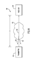
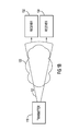
- Figs. 1A-1C illustrate various system configurations for remote absorption spectroscopy embodying the present general inventive concept
- Fig. 2 is a high level diagram of an exemplary remote absorption spectrometer (RAS) embodying the present general inventive concept;
- RAS remote absorption spectrometer
- Fig. 3A is a schematic block diagram of an exemplary optical RAS transmitter embodying the present general inventive concept
- Fig. 3B is a schematic block diagram of an exemplary optical RAS receiver embodying the present general inventive concept
- Fig. 4 is a flow diagram of a transmission process embodying the present general inventive concept.
- Fig. 5 is a flow diagram of an exemplary analysis process embodying the present general inventive concept.
- FIG. 1A there is illustrated an exemplary remote absorption spectrometer (RAS) 100 by which the present invention can be embodied.
- a transmitter 110 and a receiver 130 are separated by a distance D and the volume between transmitter 110 and receiver 130 is occupied by a medium 120 to be analyzed.
- transmitter 110 transmits a multispectral electromagnetic beam 125 through medium 120 to receiver 130, which accepts and analyzes electromagnetic beam 125 as transformed by properties of medium 120.
- At least one spectral band of beam 125 is selected to correspond to an absorption band of the constituent of medium 120 that is to be measured.
- Other spectral bands of beam 125 may be selected to coincide with other absorption bands, and still others may be used as reference signals.
- Transmitter 110 may define and control a relationship between certain spectral components of beam 125, and provide knowledge of such relationship to receiver 130.
- spectral component refers to a constituent spectral element of electromagnetic radiation and the term spectral content refers to the spectral makeup of the radiation over a predetermined range thereof.
- spectral components are distributed over the spectrum of the radiation to comprise the spectral content thereof.
- Receiver 130 may analyze the received spectral components of beam 125 and resolve absorption properties of medium 120 from the knowledge of the transmitted spectrum. Receiver 130 may make certain corrections to compensate for the system configuration and path-dependent variables caused by such configuration.
- RAS 100 may be deployed in medium 120 that is substantially unbounded, such as the atmosphere and, as illustrated in Fig. 1A , 125 may be transmitted from transmitter 110 to receiver 130 through line-of-sight propagation.
- line-of-sight propagation refers to propagation of electromagnetic radiation in a direction from transmitter 110 to receiver 130 so as to exclude detection and processing of electromagnetic radiation propagating towards transmitter 110, such as by scattering 122 illustrated in Fig. 1A .
- line-of-sight propagation does not exclude the use of reflectors as long as such reflection is excluded from traversing the transmitted beam.
- Transmitter 110 and receiver 130 may be arbitrarily locatable such that the path length D through medium 120 can be varied on a deployment basis.
- Distance D between transmitter 110 and receiver 130 may be limited by system configuration, e.g., transmitter power and receiver sensitivity, but the present invention may be embodied for distances ranging from a few meters to hundreds of kilometers, as will be appreciated by the ordinarily skilled artisan upon review of this disclosure.
- an alternative embodiment allows transmitter 110 to transmit a beam 127 through a medium 122, where such beam is of sufficient width to be received simultaneously through line-of-sight propagation at multiple receivers 132, 134.
- Electromagnetic beam 127 may be spectrally similar to that described with reference to Fig. 1A , but with a broader beamwidth established through suitable beamforming techniques at transmitter 110.
- transmitter 110 may be transported through a trajectory 140, such as by aircraft or by satellite, and an electromagnetic beam, representatively illustrated as beam 128, 128' and 128", may be received through line-of-sight propagation through medium 124 at distributed receivers 136-138 as transmitter 110 moves along trajectory 140.
- the absorption analysis performed at each receiver may be aggregated in a manner that provides an absorption profile of an extended region in space.
- RAS 200 comprises a transmitter 210 to transmit an electromagnetic beam 240, indicated as transmitted beam 240', and a receiver 260 to receive beam 240, indicated as received beam 240", and to determine therefrom absorption characteristics of a medium through which beam 240 passes.
- exemplary transmitter 210 is implemented through radiation generator 212, which may include radiation sources, such as, for example, lasers, diodes, magnetrons, vacuum tubes, etc., and radiation processing systems, such as, for example, focusing optics, modulators, filters, level monitors, etc.
- Transmitter 210 may include further a beamforming system 220, through which transmitted beam 240' is formed and delivered to the medium under study.
- Beamforming system 220 may include beamforming components suitable to the operating electromagnetic band of the RAS 200, including, but not limited to refractive elements, such as lenses, reflective elements, such as mirrors, radiators, such as antennas, frequency-selective elements, such as filters, and other elements by which beam 240 can be transmitted in a desired beam pattern.
- refractive elements such as lenses
- reflective elements such as mirrors
- radiators such as antennas
- frequency-selective elements such as filters
- Exemplary transmitter 210 includes a controller 218, through which the spectral content of transmitted beam 240' is established and controlled.
- Beam 240 includes, for example, spectral components C A ( ⁇ ABS ), referred to herein as components 242, and spectral components C B ( ⁇ REF ), referred to herein as components 244, where C A (•) and C B (•) are modulation coding functions on electromagnetic radiation having wavelengths ⁇ ABS and ⁇ REF , respectively.
- the notation C X ( ⁇ X ) carries with it the implication of an electromagnetic spectrum containing spectral components ⁇ X generated by radiation sources, such as lasers, and spectral components generated by the application of coding function C X (•) on ⁇ X , such as through modulation.
- Wavelength ⁇ ABS may be chosen to coincide with an absorption band of a chemical constituent of the medium under study and ⁇ REF may be chosen to lie in an off-line band for purposes of reference.
- an off-line band is a band in the electromagnetic spectrum of beam 240 that excludes ⁇ ABS .
- ⁇ REF is chosen to lie in a spectral region where absorption is less than that at ⁇ ABS .
- Coding functions C A (•) and C B (•) may be chosen to differentiate spectral components 242, 244 at receiver 260 and may be chosen to take on temporally-variable states, such as in amplitude, phase, etc., so that spectral properties of beam 240 can be controlled per a prescribed criterion.
- C A (•) and C B (•) may be independent amplitude modulation functions of different modulation frequencies that can identify respective components 242, 244.
- the amplitudes of the modulation functions can be independently varied to control spectral energy in each of the transmitted components 242, 244, denoted herein as P( ⁇ ABS ) and P( ⁇ REF ).
- the modulation amplitudes may be controlled so that P( ⁇ ABS ) and P( ⁇ REF ) are relatively maintained in accordance with a prescribed relationship, which may be, for example, proportionality.
- a prescribed relationship which may be, for example, proportionality.
- P( ⁇ ABS ) and P( ⁇ REF ) are constant at transmitter 210
- variations in that relationship at receiver 260 can be attributed with confidence to absorption by the medium.
- the ordinarily skilled artisan may recognize other coding schemes that may be used in conjunction with the present invention without departing from the spirit and intended scope thereof. The scope of the present invention is intended to embrace such alternative schemes.
- C A (•) and C B (•) on ⁇ ABS and ⁇ REF may redistribute the energy of the spectral content of beam 240. Such redistribution may be over a very large spectral range.
- ⁇ ABS may be 1.5711194 microns and ⁇ REF may be 1.57116194 microns.
- C A (•) may be sinusoidal amplitude modulation at, say, 50 kHz and C B (•) may be sinusoidal amplitude modulation at, say, 53 kHz.
- C A (•) is applied to ⁇ ABS , some of the energy originally at 1.5711194 microns is redistributed to 6.0 km.
- C B (•) redistributes some of the energy originally at 1.57116194 microns to 5.7 km.
- Receiver 260 may be configured to reject radiation outside, say, the micron range and, as such, would certainly not detect changes in energy levels in the kilometer range.
- changes in energy levels in the band containing 1.5711194-1.57116194 microns may be detectable at receiver 260 and, as such, the 50 and 53 kHz modulation may be used to control detectable levels of energy contained at those wavelengths. This control may be leveraged by embodiments of the present invention to maintain a relationship between ⁇ ABS and ⁇ REF at transmitter 210 and to detect changes in that relationship at receiver 260.
- electrical signal 213 may be generated by controller 218 to define and maintain the relationship between components 242, 244 in transmitted beam 240'. Additionally, generator 212 may provide one or more electrical signals 215 to controller 218 that is indicative of the spectral content of transmitted beam 240'. From such indication provided in signal 215, controller 218 may determine whether the prescribed relationship between components 242, 244 is properly maintained and may make suitable adjustments to electrical signal 213 accordingly.
- Exemplary receiver 260 includes a collector 250 through which received beam 240" is accepted and provided to a detector 262.
- Collector 250 may include focusing elements by which beam 240" is focused onto an active area of detector 262, in response to which one or more electrical signals 263 may be generated.
- Electrical signal 263 may represent the spectral content of the received beam 240", i.e., the spectral content of beam 240 as transformed by the medium through which it has travelled.
- Electrical signal 263 may be provided to an analyzer 264, which may perform suitable spectral analyses on the received beam 240" to determine whether a deviation in the spectral content thereof is carried in the relationship between spectral components 242, 244 of the transmitted beam 240'. If so, as discussed above, the deviation may be reported as due to absorption of one or more of those spectral components by the medium.
- Transmitter 210 and receiver 260 may be located along a line-of-sight path so that beam 240 can pass unidirectionally through the medium under scrutiny. That is, transmitter 210 and receiver 260 may be positioned in space such that scattered radiation from beam 240 in other than the forward direction from transmitter 210 is isolated from detector 262. Thus, absorption measurements by RAS 200 are free from noise contamination caused by backscattering, as is the case with conventional atmospheric absorption spectrometers.
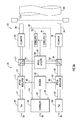
- Fig. 3A illustrates an exemplary transmitter 303
- Fig. 3B illustrates an exemplary receiver 307 of an optical RAS 300
- exemplary transmitter 303 comprises two optical channels: an absorption wavelength channel 302 and a reference wavelength channel 304.
- Optical channels 302, 304 incorporate respective optical radiation sources 310, 320, optical modulators 312, 322, beamsplitters 314, 324 and collimators 316, 326.
- the output of absorption channel 302 is a set of spectral components 382 and the output of reference channel 304 is a set of spectral components 384, both of which may be transmitted through a common aperture 370 in beam 380.
- aperture 370 may be other than a physical optical stop and it is to be understood that the explicit illustration of aperture 370 is to define an optical boundary of transmitter 303 for purposes of description and not limitation.
- Radiation sources 310, 320 may be implemented by respective lasers emitting coherent light at wavelengths ⁇ ABS and ⁇ REF , referred to herein as laser light 311 and laser light 321, respectively.
- Laser light 311, 321 may be modulated by optical modulators 312, 322 in accordance with selected codes.
- Optical modulators 312, 322 may be electro-optical devices independently operated at modulation frequencies suitable to apply the respective codes on laser light 311, 321.
- the modulated laser light 313, 323 may be sampled through the use of beamsplitters 314, 324, as will be described below, and provided to collimators 316, 326.
- Collimators 316, 326 may be implemented by suitable beam expanders through which the modulated light 313, 323 emerges from aperture 370 as a beam 380. It is to be understood that while, in certain embodiments, components 382, 384 may emerge from transmitter 303 in separate beams, such separated beams will be referred to herein as if such were contained in a single beam 380 for purposes of description and not limitation. It is to be understood further that, while separate collimators 316, 326 are illustrated in Fig. 3A , modulated light 313, 323 may be expanded through a single common collimator, as will be recognized by those skilled in the optical arts.
- Exemplary transmitter 303 includes a control channel 306, by which the spectral content of optical channels 302, 304 is established and controlled.
- Control channel 306 may be implemented through suitable hardware, firmware and/or programmable processing hardware executing software, and may be constructed through analog and/or digital hardware. The ordinarily skilled artisan will readily recognize numerous control schemes by which control channel 306 can be embodied upon review of this disclosure. The scope of the present invention is intended to embrace all such embodiments of control channel 306.
- Exemplary control channel 306 includes an encoder 340 to generate modulation codes in accordance with an electrical signal 332 provided thereto.
- RAS 300 is not limited to particular modulation codes; the codes can be chosen on an application basis in consideration of, for example, modulation and detection capabilities of the system components of RAS 300.
- Encoder 340 may generate electrical signals 342, 344 by which modulators 312, 322 are independently operated to apply the modulation codes on each optical channel 302, 304.
- Encoder 340 may generate, for example, amplitude modulation codes that are fixed in frequency.
- Control signal 332 may indicate to encoder 340 amplitude levels of respective codes applied to channels 302, 304 so that the relationship between spectral components 382, 384 is maintained.
- the relationship is a predetermined ratio between the transmitted optical energy in components 382 and that of components 384.
- exemplary encoder 340 modifies the amplitude of one or both codes in each optical channel 302, 304 so as to maintain the transmitted energy ratio.
- Electrical signals 342, 344 may be provided to modulators 312, 322, whereby modulated laser light 313, 323 is produced in each channel 302, 304.
- Modulated light 313, 323 may be sampled, such as through beamsplitters 314, 324 and optical detector 350 for purposes of monitoring and control of the relationship between spectral components 382, 384.
- Optical detector 350 may be a monolithic optical device having a single active area sufficient in dimension to receive sampled beams 315, 325.
- focusing optics (not illustrated) may be inserted into the path between sampled beams 315, 325 and the active area of detector 350.
- Optical detector 350 should have sufficient dynamic range so as to respond to changes in the spectral range encompassing ⁇ ABS and ⁇ REF as modulation in each optical channel 302, 304 varies.
- Detector 350 may generate an electrical signal 352 representative of changing spectral conditions in beam 380, which may be provided to a discriminator 360. Discriminator may, in turn, generate electrical signals 334, 336 indicative of the changing spectral conditions in each channel 302, 304, which may be provided to controller 330.
- Exemplary discriminator 362 includes correlators 362, 364, each configured in accordance with the modulation code of a corresponding optical channel 302, 304. Such correlators 362, 364 may be implemented through matched filters tuned to the modulation code in the corresponding optical channel 302, 304.
- each correlator 362, 364 is a time-varying electrical signal 334, 336 indicative of the spectral energy transmitted in components 382, 384, which is proportional to the energy transmitted at wavelengths ⁇ ABS and ⁇ REF , respectively.
- a non-zero deviation ⁇ r may be reflected in control signal 332, responsive to which encoder 340 makes suitable adjustments to signals 342, 344 to increase and/or decrease P( ⁇ ABS ) and/or P( ⁇ REF ) in one or both of modulated light beams 313, 323.
- Fig. 3B illustrates an exemplary receiver 307 for RAS 300.
- Receiver 307 may include receiving optics, such as telescope 370, by which beam 380, as transmitted by transmitter 303 and transformed by the medium under study, is accepted and focused onto detector 373.
- Detector 373 may be of construction similar, if not identical, to that of detector 350, although the present invention is not so limited.
- Detector 373 may generate an electrical signal 374 indicative of the changing spectral conditions in the received beam 380.
- the detector signal 374 may be provided to a discriminator 375, which may be of construction similar, if not identical, to that of discriminator 360, i.e., through correlators 377, 379, although the present invention is not so limited.
- Exemplary absorption processor 395 determines absorption in the medium at ⁇ ABS from an evaluation of r eval /r 0 .
- RAS 300 is embodied to precisely govern the spectral content of beam 380 so that ⁇ ABS lies in the absorption band of interest, ⁇ REF is outside the absorption band of interest and the transmitted ratio P( ⁇ ABS )/P( ⁇ REF ) is maintained at r 0 . Accordingly, absent any absorption at ⁇ ABS by the medium, r eval /r 0 is substantially unity. Deviations from unity in the evaluation of r eval /r 0 can be attributed, with a reasonable degree of confidence, to absorption of the medium at ⁇ ABS .
- Absorption processor 395 may apply correction measures on r eval /r 0 to account for, among other things, length of the transmission path, the direction of beam 380 through the medium, beam dispersion, the number of receivers and the manner in which the transmitted radiation is accepted thereby, e.g., simultaneous reception, temporally sequential, etc.
- An indication of compensated r eval /r 0 may be conveyed in a signal 396 to a reporter 397, which may format results of the analysis by absorption processor 460 in a manner perceivable by a human user.
- Fig. 4 illustrates an exemplary transmission process 400 by which a RAS may transmit radiation for analysis by a receiver.
- radiation in respective channels such as those illustrated by channels 302, 304 of RAS 300, is modulated in accordance with codes assigned to each channel.
- the modulated radiation is combined in operation 410, such as by provision to a common detector 350, and, in operation 415, the combined radiation is distinguished into separate components, e.g., the spectral component in the absorption band and the spectral component in the off-line band, such as by discriminator 360.
- the distinguished spectral components are evaluated to determine whether a relationship therebetween defined by the codes is within a predetermined range. If not, the modulation is adjusted in operation 430, such as by increasing or decreasing modulation amplitude, to maintain the relationship. If the relationship is within tolerance, as determined in operation 425, the components are transmitted in a beam in operation 435.
- Fig. 5 illustrates an exemplary analysis process 500 usable with transmission process 400.
- an electrical signal is obtained from the transmitted beam, such as by detector 420.
- the spectral components are distinguished, such as in a manner similar to that of operation 415 in process 400, and the signals are integrated over a selected time interval in operation 515, such as by integrator 430.
- the integrated spectral components are evaluated to determine whether a deviation exists in the relationship therebetween defined by the codes and the relationship between the received spectral components.
- such deviation is compensated for system and transmission path-dependent variability and the corrected deviation is reported as absorption by the medium in operation 530.
Landscapes
- Physics & Mathematics (AREA)
- Spectroscopy & Molecular Physics (AREA)
- General Physics & Mathematics (AREA)
- Health & Medical Sciences (AREA)
- Life Sciences & Earth Sciences (AREA)
- Chemical & Material Sciences (AREA)
- Analytical Chemistry (AREA)
- Biochemistry (AREA)
- General Health & Medical Sciences (AREA)
- Immunology (AREA)
- Pathology (AREA)
- Investigating Or Analysing Materials By Optical Means (AREA)
Abstract
Description
- Conventional active source absorption spectroscopy systems for analyzing gases, such as CO2, CH4, O2, etc. implement collocated transmitter and receiver components and, as such, require a short path length or reflections to return transmitted signals to the source location. Over long distances, the transmitted signals are reflected off mirrors or the ground to effect the return of the signal to the collocated receiver. Scattered returns from aerosol constituents or particles in these systems give rise to an additive error from backscattered radiation. This error effectively reduces the measured absorption, since the backscattered return completes only a partial path through the medium being analyzed. Additionally, if the reflector used is diffuse, large range-squared losses in the system result, prohibiting long-range implementation of the overall system.
- In light of the shortcomings of these and other techniques, the need has been felt for a technique to measure constituents in a medium or the atmosphere so that partial path scattered return is ignored and to reduce transmission power losses where only diffuse targets exist for reflecting transmitted radiation.
- Described herein is a technique applicable to remote absorption spectroscopy using spatially isolated and arbitrarily located transmitter and receiver subsystems. Multispectral electromagnetic radiation may be generated to have spectral content coinciding with both an absorption band of a medium and an off-line band. The radiation may be modified prior to transmission, such as by a set of codes, to define a relationship between at least one spectral component in the absorption band and at least one spectral component in the off-line band. This relationship is controlled to be temporally constant and is known at the receiver. The receiver accepts the transmitted radiation through line-of-sight propagation through the medium and the spectral content of the received radiation is analyzed. Deviation of the spectral content of the received radiation from the relationship defined by the transmitter may be attributable to absorption by the medium of the spectral component inside the absorption.
- The above and still further features and advantages of the present inventive concept will become apparent upon consideration of the following definitions, descriptions and descriptive figures of specific embodiments thereof. While these descriptions go into specific details of certain embodiments of the inventive concept, it is to be understood that variations may and do exist and will be apparent to those skilled in the art upon review of this disclosure.
-
Figs. 1A-1C illustrate various system configurations for remote absorption spectroscopy embodying the present general inventive concept; -
Fig. 2 is a high level diagram of an exemplary remote absorption spectrometer (RAS) embodying the present general inventive concept; -
Fig. 3A is a schematic block diagram of an exemplary optical RAS transmitter embodying the present general inventive concept; -
Fig. 3B is a schematic block diagram of an exemplary optical RAS receiver embodying the present general inventive concept; -
Fig. 4 is a flow diagram of a transmission process embodying the present general inventive concept; and -
Fig. 5 is a flow diagram of an exemplary analysis process embodying the present general inventive concept. - The present inventive concept is best described through certain embodiments thereof, which are described in detail herein with reference to the accompanying drawings, wherein like reference numerals refer to like features throughout. It is to be understood that the term invention, when used herein, is intended to connote the inventive concept underlying the embodiments described below and not merely the embodiments themselves. It is to be understood further that the general inventive concept is not limited to the illustrative embodiments described below and the following descriptions should be read in such light.
- Additionally, mathematical expressions may be contained herein and those principles conveyed thereby are to be taken as being thoroughly described therewith. It is to be understood that where mathematics are used, such is for succinct description of the underlying principles being explained and, unless otherwise expressed, no other purpose is implied or should be inferred. It will be clear from this disclosure overall how the mathematics herein pertain to the present invention and, where embodiment of the principles underlying the mathematical expressions is intended, the ordinarily skilled artisan will recognize numerous techniques to carry out physical manifestations of the principles being mathematically expressed.
- In
Fig. 1A , there is illustrated an exemplary remote absorption spectrometer (RAS) 100 by which the present invention can be embodied. Atransmitter 110 and areceiver 130 are separated by a distance D and the volume betweentransmitter 110 andreceiver 130 is occupied by amedium 120 to be analyzed. Toward that end,transmitter 110 transmits a multispectralelectromagnetic beam 125 throughmedium 120 toreceiver 130, which accepts and analyzeselectromagnetic beam 125 as transformed by properties ofmedium 120. At least one spectral band ofbeam 125 is selected to correspond to an absorption band of the constituent ofmedium 120 that is to be measured. Other spectral bands ofbeam 125 may be selected to coincide with other absorption bands, and still others may be used as reference signals. -
Transmitter 110 may define and control a relationship between certain spectral components ofbeam 125, and provide knowledge of such relationship toreceiver 130. As used herein, the term spectral component refers to a constituent spectral element of electromagnetic radiation and the term spectral content refers to the spectral makeup of the radiation over a predetermined range thereof. Thus, spectral components are distributed over the spectrum of the radiation to comprise the spectral content thereof.Receiver 130 may analyze the received spectral components ofbeam 125 and resolve absorption properties ofmedium 120 from the knowledge of the transmitted spectrum.Receiver 130 may make certain corrections to compensate for the system configuration and path-dependent variables caused by such configuration. - RAS 100 may be deployed in
medium 120 that is substantially unbounded, such as the atmosphere and, as illustrated inFig. 1A , 125 may be transmitted fromtransmitter 110 toreceiver 130 through line-of-sight propagation. As used herein, the term line-of-sight propagation refers to propagation of electromagnetic radiation in a direction fromtransmitter 110 toreceiver 130 so as to exclude detection and processing of electromagnetic radiation propagating towardstransmitter 110, such as by scattering 122 illustrated inFig. 1A . Under this definition, line-of-sight propagation does not exclude the use of reflectors as long as such reflection is excluded from traversing the transmitted beam. -
Transmitter 110 andreceiver 130 may be arbitrarily locatable such that the path length D throughmedium 120 can be varied on a deployment basis. Distance D betweentransmitter 110 andreceiver 130 may be limited by system configuration, e.g., transmitter power and receiver sensitivity, but the present invention may be embodied for distances ranging from a few meters to hundreds of kilometers, as will be appreciated by the ordinarily skilled artisan upon review of this disclosure. - In
Fig. 1B , an alternative embodiment allowstransmitter 110 to transmit abeam 127 through amedium 122, where such beam is of sufficient width to be received simultaneously through line-of-sight propagation atmultiple receivers Electromagnetic beam 127 may be spectrally similar to that described with reference toFig. 1A , but with a broader beamwidth established through suitable beamforming techniques attransmitter 110. In yet a further implementation illustrated inFig. 1C ,transmitter 110 may be transported through atrajectory 140, such as by aircraft or by satellite, and an electromagnetic beam, representatively illustrated asbeam medium 124 at distributed receivers 136-138 astransmitter 110 moves alongtrajectory 140. When multiple receivers are used, such as in the configurations ofFig. 1B andFig. 1C , the absorption analysis performed at each receiver may be aggregated in a manner that provides an absorption profile of an extended region in space. - In the exemplary embodiment illustrated in
Fig. 2 , RAS 200 comprises atransmitter 210 to transmit anelectromagnetic beam 240, indicated as transmitted beam 240', and areceiver 260 to receivebeam 240, indicated as receivedbeam 240", and to determine therefrom absorption characteristics of a medium through whichbeam 240 passes.Exemplary transmitter 210 is implemented throughradiation generator 212, which may include radiation sources, such as, for example, lasers, diodes, magnetrons, vacuum tubes, etc., and radiation processing systems, such as, for example, focusing optics, modulators, filters, level monitors, etc.Transmitter 210 may include further abeamforming system 220, through which transmitted beam 240' is formed and delivered to the medium under study.Beamforming system 220 may include beamforming components suitable to the operating electromagnetic band of the RAS 200, including, but not limited to refractive elements, such as lenses, reflective elements, such as mirrors, radiators, such as antennas, frequency-selective elements, such as filters, and other elements by whichbeam 240 can be transmitted in a desired beam pattern. -
Exemplary transmitter 210 includes acontroller 218, through which the spectral content of transmitted beam 240' is established and controlled.Beam 240 includes, for example, spectral components CA(λABS), referred to herein ascomponents 242, and spectral components CB(λREF), referred to herein ascomponents 244, where CA(•) and CB(•) are modulation coding functions on electromagnetic radiation having wavelengths λABS and λREF, respectively. It is to be understood that the notation CX(λX) carries with it the implication of an electromagnetic spectrum containing spectral components λX generated by radiation sources, such as lasers, and spectral components generated by the application of coding function CX(•) on λX, such as through modulation. - Wavelength λABS may be chosen to coincide with an absorption band of a chemical constituent of the medium under study and λREF may be chosen to lie in an off-line band for purposes of reference. As used herein, an off-line band is a band in the electromagnetic spectrum of
beam 240 that excludes λABS. In certain embodiments, λREF is chosen to lie in a spectral region where absorption is less than that at λABS. - Coding functions CA(•) and CB(•) may be chosen to differentiate
spectral components receiver 260 and may be chosen to take on temporally-variable states, such as in amplitude, phase, etc., so that spectral properties ofbeam 240 can be controlled per a prescribed criterion. For example, CA(•) and CB(•) may be independent amplitude modulation functions of different modulation frequencies that can identifyrespective components components receiver 260, under the assumption that the relationship between P(λABS) and P(λREF) is constant attransmitter 210, variations in that relationship atreceiver 260 can be attributed with confidence to absorption by the medium. The ordinarily skilled artisan may recognize other coding schemes that may be used in conjunction with the present invention without departing from the spirit and intended scope thereof. The scope of the present invention is intended to embrace such alternative schemes. - The application of CA(•) and CB(•) on λABS and λREF may redistribute the energy of the spectral content of
beam 240. Such redistribution may be over a very large spectral range. For example, to measure absorption of CO2, λABS may be 1.5711194 microns and λREF may be 1.57116194 microns. CA(•) may be sinusoidal amplitude modulation at, say, 50 kHz and CB(•) may be sinusoidal amplitude modulation at, say, 53 kHz. When CA(•) is applied to λABS, some of the energy originally at 1.5711194 microns is redistributed to 6.0 km. Similarly, the application of CB(•) to λREF redistributes some of the energy originally at 1.57116194 microns to 5.7 km.Receiver 260 may be configured to reject radiation outside, say, the micron range and, as such, would certainly not detect changes in energy levels in the kilometer range. However, changes in energy levels in the band containing 1.5711194-1.57116194 microns may be detectable atreceiver 260 and, as such, the 50 and 53 kHz modulation may be used to control detectable levels of energy contained at those wavelengths. This control may be leveraged by embodiments of the present invention to maintain a relationship between λABS and λREF attransmitter 210 and to detect changes in that relationship atreceiver 260. - As illustrated in
Fig. 2 ,electrical signal 213 may be generated bycontroller 218 to define and maintain the relationship betweencomponents generator 212 may provide one or moreelectrical signals 215 tocontroller 218 that is indicative of the spectral content of transmitted beam 240'. From such indication provided insignal 215,controller 218 may determine whether the prescribed relationship betweencomponents electrical signal 213 accordingly. -
Exemplary receiver 260 includes acollector 250 through which receivedbeam 240" is accepted and provided to adetector 262.Collector 250 may include focusing elements by whichbeam 240" is focused onto an active area ofdetector 262, in response to which one or moreelectrical signals 263 may be generated.Electrical signal 263 may represent the spectral content of the receivedbeam 240", i.e., the spectral content ofbeam 240 as transformed by the medium through which it has travelled.Electrical signal 263 may be provided to ananalyzer 264, which may perform suitable spectral analyses on the receivedbeam 240" to determine whether a deviation in the spectral content thereof is carried in the relationship betweenspectral components -
Transmitter 210 andreceiver 260 may be located along a line-of-sight path so thatbeam 240 can pass unidirectionally through the medium under scrutiny. That is,transmitter 210 andreceiver 260 may be positioned in space such that scattered radiation frombeam 240 in other than the forward direction fromtransmitter 210 is isolated fromdetector 262. Thus, absorption measurements byRAS 200 are free from noise contamination caused by backscattering, as is the case with conventional atmospheric absorption spectrometers. -
Fig. 3A illustrates anexemplary transmitter 303 andFig. 3B illustrates anexemplary receiver 307 of anoptical RAS 300. Referring first toFig. 3A ,exemplary transmitter 303 comprises two optical channels: anabsorption wavelength channel 302 and areference wavelength channel 304.Optical channels optical radiation sources optical modulators beamsplitters collimators absorption channel 302 is a set ofspectral components 382 and the output ofreference channel 304 is a set ofspectral components 384, both of which may be transmitted through acommon aperture 370 inbeam 380. The ordinarily skilled artisan will recognize and appreciate thataperture 370 may be other than a physical optical stop and it is to be understood that the explicit illustration ofaperture 370 is to define an optical boundary oftransmitter 303 for purposes of description and not limitation. -
Radiation sources laser light 311 andlaser light 321, respectively.Laser light optical modulators Optical modulators laser light laser light beamsplitters collimators Collimators light aperture 370 as abeam 380. It is to be understood that while, in certain embodiments,components transmitter 303 in separate beams, such separated beams will be referred to herein as if such were contained in asingle beam 380 for purposes of description and not limitation. It is to be understood further that, whileseparate collimators Fig. 3A , modulated light 313, 323 may be expanded through a single common collimator, as will be recognized by those skilled in the optical arts. -
Exemplary transmitter 303 includes acontrol channel 306, by which the spectral content ofoptical channels Control channel 306 may be implemented through suitable hardware, firmware and/or programmable processing hardware executing software, and may be constructed through analog and/or digital hardware. The ordinarily skilled artisan will readily recognize numerous control schemes by whichcontrol channel 306 can be embodied upon review of this disclosure. The scope of the present invention is intended to embrace all such embodiments ofcontrol channel 306. -
Exemplary control channel 306 includes anencoder 340 to generate modulation codes in accordance with anelectrical signal 332 provided thereto.RAS 300 is not limited to particular modulation codes; the codes can be chosen on an application basis in consideration of, for example, modulation and detection capabilities of the system components ofRAS 300.Encoder 340 may generateelectrical signals optical channel Encoder 340 may generate, for example, amplitude modulation codes that are fixed in frequency.Control signal 332 may indicate toencoder 340 amplitude levels of respective codes applied tochannels spectral components components 382 and that ofcomponents 384. When so embodied,exemplary encoder 340 modifies the amplitude of one or both codes in eachoptical channel Electrical signals modulators laser light channel - Modulated light 313, 323 may be sampled, such as through
beamsplitters optical detector 350 for purposes of monitoring and control of the relationship betweenspectral components Optical detector 350 may be a monolithic optical device having a single active area sufficient in dimension to receive sampledbeams beams detector 350.Optical detector 350 should have sufficient dynamic range so as to respond to changes in the spectral range encompassing λABS and λREF as modulation in eachoptical channel -
Detector 350 may generate anelectrical signal 352 representative of changing spectral conditions inbeam 380, which may be provided to adiscriminator 360. Discriminator may, in turn, generateelectrical signals channel controller 330.Exemplary discriminator 362 includescorrelators optical channel Such correlators optical channel electrical signal components -
Exemplary controller 330 is provided withsignals channel detector 350 for channel X and extracted bydiscriminator 360,controller 330 may evaluate P(λABS)/P(λREF) fromsignals signals control signal 332, responsive to whichencoder 340 makes suitable adjustments tosignals light beams -
Fig. 3B illustrates anexemplary receiver 307 forRAS 300.Receiver 307 may include receiving optics, such astelescope 370, by whichbeam 380, as transmitted bytransmitter 303 and transformed by the medium under study, is accepted and focused ontodetector 373.Detector 373 may be of construction similar, if not identical, to that ofdetector 350, although the present invention is not so limited.Detector 373 may generate anelectrical signal 374 indicative of the changing spectral conditions in the receivedbeam 380. Thedetector signal 374 may be provided to adiscriminator 375, which may be of construction similar, if not identical, to that ofdiscriminator 360, i.e., throughcorrelators discriminator 375, are proportional to the spectral energy of each spectral component λABS and λREF and may be provided torespective integrators signals integrators transmitter 303 andreceiver 307 and composition of the medium.Signals ratio processor 390, whereby the relationship reval = P(λABS)/P(λREF) is evaluated in a manner similar, if not identical, to the evaluation preformed bycontroller 330, although the present invention is not so limited. The receivedratio processor 390 may generate anelectrical signal 396 indicative of the evaluated ratio reval which may be provided toabsorption processor 397. -
Exemplary absorption processor 395 determines absorption in the medium at λABS from an evaluation of reval/r0. As discussed,RAS 300 is embodied to precisely govern the spectral content ofbeam 380 so that λABS lies in the absorption band of interest, λREF is outside the absorption band of interest and the transmitted ratio P(λABS)/P(λREF) is maintained at r0. Accordingly, absent any absorption at λABS by the medium, reval/r0 is substantially unity. Deviations from unity in the evaluation of reval/r0 can be attributed, with a reasonable degree of confidence, to absorption of the medium at λABS.Absorption processor 395 may apply correction measures on reval/r0 to account for, among other things, length of the transmission path, the direction ofbeam 380 through the medium, beam dispersion, the number of receivers and the manner in which the transmitted radiation is accepted thereby, e.g., simultaneous reception, temporally sequential, etc. An indication of compensated reval/r0 may be conveyed in asignal 396 to areporter 397, which may format results of the analysis by absorption processor 460 in a manner perceivable by a human user. - It is to be understood that the separation of functionality of components illustrated in
Figs. 3A-3B is solely for purposes of description and not limitation. Numerous alternative system configurations may implement aRAS 300 without departing from the spirit and intended scope thereof. -
Fig. 4 illustrates anexemplary transmission process 400 by which a RAS may transmit radiation for analysis by a receiver. Inoperation 405, radiation in respective channels, such as those illustrated bychannels RAS 300, is modulated in accordance with codes assigned to each channel. The modulated radiation is combined inoperation 410, such as by provision to acommon detector 350, and, inoperation 415, the combined radiation is distinguished into separate components, e.g., the spectral component in the absorption band and the spectral component in the off-line band, such as bydiscriminator 360. Inoperations operation 430, such as by increasing or decreasing modulation amplitude, to maintain the relationship. If the relationship is within tolerance, as determined inoperation 425, the components are transmitted in a beam inoperation 435. -
Fig. 5 illustrates anexemplary analysis process 500 usable withtransmission process 400. Inoperation 505, an electrical signal is obtained from the transmitted beam, such as bydetector 420. Inoperation 510, the spectral components are distinguished, such as in a manner similar to that ofoperation 415 inprocess 400, and the signals are integrated over a selected time interval inoperation 515, such as byintegrator 430. Inoperation 520, the integrated spectral components are evaluated to determine whether a deviation exists in the relationship therebetween defined by the codes and the relationship between the received spectral components. Inoperation 525, such deviation is compensated for system and transmission path-dependent variability and the corrected deviation is reported as absorption by the medium inoperation 530. - The descriptions above are intended to illustrate possible implementations of the present inventive concept and are not restrictive. Many variations, modifications and alternatives will become apparent to the skilled artisan upon review of this disclosure. For example, components equivalent to those shown and described may be substituted therefore, elements and methods individually described may be combined, and elements described as discrete may be distributed across many components. The scope of the invention should therefore be determined not with reference to the description above, but with reference to the appended claims, along with their full range of equivalents.
Claims (14)
- An apparatus comprising:a generator to generate multispectral electromagnetic radiation having spectral content coinciding with an absorption band of a medium and with an off-line band thereof;a transmitter to modify the generated spectral content to define a relationship between at least one spectral component thereof inside the absorption band and at least one spectral component thereof in the off-line band, and to transmit the modified radiation through the medium; andat least one receiver spatially isolated from the transmitter and arbitrarily locatable with respect thereto to accept the transmitted radiation through line-of-sight propagation through the medium, the receiver evaluating the spectral content of the received radiation for a deviation thereof from the relationship defined by the transmitter and to determine therefrom absorption by the medium of the spectral component inside the absorption band.
- The apparatus of claim 1, wherein the transmitter includes:a radiation channel for each spectral component in the absorption band and for each spectral component in the off-line band, each radiation channel modifying the corresponding spectral component such that the relationship therebetween is maintained, an in particulara modulator in each radiation channel to modulate the corresponding spectral component by respective modulation codes in accordance with respective control signals provided thereto;a detector to generate an electrical signal from the modulated radiation incident thereon from at least the radiation channel of the spectral component in the absorption band and the radiation channel of the spectral component in the off-line band; anda controller to generate the control signals responsive to the detector signal so as to maintain the relationship between the spectral component in the absorption band and the spectral component in the off-line band, and further in particularwherein the controller includes- an encoder to generate modulation codes for respective radiation channels and to provide an indication of the codes in the control signals, the encoder modifying a parameter of the codes so as to maintain the relationship between the spectral component in the absorption band and the spectral component in the off-line band; and/or- a discriminator to generate electrical signals responsive to the signal from the detector such that the discriminator signals represent transmitted energy in the modulated spectral component in the absorption band and in the modulated spectral component in the off-line band.
- The apparatus of claim 2, wherein the codes- identify the respective radiation channels of the transmitter at the receiver; and/or- are amplitude modulation codes and the parameter thereof is signal amplitude.
- The apparatus of claim 2, wherein discriminator includes a correlator for each radiation channel, the correlator being tuned to the code assigned to the corresponding radiation channel to provide a corresponding one of the discriminator signals responsive to the detector signal.
- The apparatus of claim 2, wherein the receiver includes:a detector to generate a receiver signal from the modulated radiation incident thereon; andan analyzer to generate the control signals responsive to the detector signal so as to maintain the relationship between the spectral component in the absorption band andthe spectral component in the off-line band, and in particular wherein the analyzer includesa discriminator to generate electrical signals responsive to the signal from the detector such that the discriminator signals represent energy in the modulated spectral component in the absorption band and in the modulated spectral component in the off-line band, and further in particular wherein discriminator includesa correlator for each radiation channel, the correlator being tuned to the code assigned to the corresponding radiation channel to provide a corresponding one of the discriminator signals responsive to the detector signal.
- The apparatus of claim 1, wherein the transmitter and receiver are independently locatable in a substantially boundless medium.
- The apparatus of claim 6, wherein the at least one receiver comprises a plurality of receivers substantially identical to the at least one receiver.
- The apparatus of claim 7, wherein the transmitter includes- a beamformer by which the transmitted radiation is distributed to be simultaneously accepted by the receivers; and/or- a movable platform by which the transmitter traverses a trajectory through which the radiation transmitted therefrom is accepted by the receivers in a sequence defined by the trajectory.
- A method comprising:generating by a transmitter multispectral electromagnetic radiation having spectral content coinciding with an absorption band of a medium and with an off-line band thereof;modifying the generated spectral content to define a relationship between at least one spectral component thereof inside the absorption band and at least one spectral component thereof in the off-line band;transmitting the modified radiation through the medium;accepting at a receiver the transmitted radiation through line-of-sight propagation through the medium;evaluating a deviation of the spectral content of the received radiation from that of the transmitted radiation as modified to define the relationship; anddetermining from the deviation the absorption by the medium of the spectral component inside the absorption band.
- The method of claim 9, wherein the modifying includes:encoding the spectral component inside the absorption band and the spectral component in the off-line band with respective modulation codes; andmodifying a parameter of the codes so as to maintain the relationship between the spectral component in the absorption band and the spectral component in the off-line band.
- The method of claim 10, wherein the evaluating includes:correlating a representation of the received radiation with the codes to produce a representation of the received spectral component inside the absorption band and a representation of the spectral component in the off-line band;determining a difference between the relationship between the spectral component inside the absorption band and the spectral component in the off-line band and the relationship between the received spectral component inside the absorption band and the received spectral component in the off-line band; andestablishing the difference as the deviation.
- The method of claim 1! further comprising:establishing as the relationship a proportionality between energy in the spectral component inside the absorption band and the energy in the spectral component in the off-line band.
- The method of claim 12, wherein the determining of the absorption includes:attributing to the absorption in the medium the difference in proportionality of the energy in the spectral component inside the absorption band and the energy in the spectral component in the off-line band and the proportionality of the energy in the received spectral component inside the absorption band and the energy in the received spectral component in the off-line band.
- A non-transitory computer readable medium encoded with software comprising processor-executable instructions that, when executed by a processor, cause the processor to perform functions of:encoding multispectral electromagnetic radiation with a plurality of modulation codes to define a relationship between at least one spectral component thereof inside an absorption band of a medium and at least one spectral component thereof in an off-line band;evaluating the spectral content of the encoded radiation subsequent to line-of-sight propagation thereof through the medium for a deviation from the relationship defined in the radiation prior to the line-of-sight propagation; anddetermining from the deviation absorption by the medium of the spectral component inside the absorption band.
Applications Claiming Priority (1)
| Application Number | Priority Date | Filing Date | Title |
|---|---|---|---|
| US13/285,292 US9030663B2 (en) | 2011-10-31 | 2011-10-31 | Remote absorption spectroscopy by coded transmission |
Publications (2)
| Publication Number | Publication Date |
|---|---|
| EP2587236A1 true EP2587236A1 (en) | 2013-05-01 |
| EP2587236B1 EP2587236B1 (en) | 2022-12-14 |
Family
ID=47177759
Family Applications (1)
| Application Number | Title | Priority Date | Filing Date |
|---|---|---|---|
| EP12186822.8A Active EP2587236B1 (en) | 2011-10-31 | 2012-10-01 | Remote absorption spectroscopy by coded transmission |
Country Status (7)
| Country | Link |
|---|---|
| US (1) | US9030663B2 (en) |
| EP (1) | EP2587236B1 (en) |
| JP (1) | JP6088195B2 (en) |
| KR (1) | KR101405883B1 (en) |
| CN (1) | CN103091263B (en) |
| AU (1) | AU2012227277B2 (en) |
| CA (1) | CA2788915C (en) |
Families Citing this family (7)
| Publication number | Priority date | Publication date | Assignee | Title |
|---|---|---|---|---|
| US9335265B2 (en) * | 2014-02-07 | 2016-05-10 | Agilent Technologies, Inc. | Spectrographic system utilizing a chirped, pulsed optical source |
| US10458904B2 (en) | 2015-09-28 | 2019-10-29 | Ball Aerospace & Technologies Corp. | Differential absorption lidar |
| US10895529B2 (en) * | 2017-01-26 | 2021-01-19 | Nec Corporation | Detecting system and detecting method |
| WO2018189737A1 (en) * | 2017-04-09 | 2018-10-18 | Ariel Scientific Innovations Ltd. | Method and system for spectroscopy |
| US10921245B2 (en) | 2018-06-08 | 2021-02-16 | Ball Aerospace & Technologies Corp. | Method and systems for remote emission detection and rate determination |
| CN113767274A (en) * | 2019-08-23 | 2021-12-07 | 西门子股份公司 | Gas analyzer |
| US12276543B2 (en) * | 2022-07-12 | 2025-04-15 | Interdisciplinary Consulting Corporation | Readout circuits for amplitude modulating sensors |
Citations (3)
| Publication number | Priority date | Publication date | Assignee | Title |
|---|---|---|---|---|
| US4425503A (en) * | 1980-08-05 | 1984-01-10 | The United States Of America As Represented By The Secretary Of The Army | Method for detecting the presence of a gas in an atmosphere |
| EP2096421A1 (en) * | 2008-02-29 | 2009-09-02 | Siemens Aktiengesellschaft | Apparatus and method for spectroscopic measurement of a medium and simultaneous data transmission |
| WO2010038058A1 (en) * | 2008-10-02 | 2010-04-08 | Enigma Diagnostics Limited | Fluorescence based detection methods and apparatus |
Family Cites Families (19)
| Publication number | Priority date | Publication date | Assignee | Title |
|---|---|---|---|---|
| FR2106754A5 (en) * | 1970-09-23 | 1972-05-05 | Commissariat Energie Atomique | |
| DE3277983D1 (en) * | 1981-03-02 | 1988-02-18 | Ici Plc | Method of and apparatus for monitoring gaseous pollutants |
| US4505583A (en) * | 1981-04-10 | 1985-03-19 | Masaaki Konomi | Spectroscopic analyzer system for examining intravital tissue |
| US4594511A (en) | 1985-03-29 | 1986-06-10 | Sri International | Method and apparatus for double modulation spectroscopy |
| US4998017A (en) * | 1989-05-01 | 1991-03-05 | Ryan Fredrick M | Method and arrangement for measuring the optical absorptions of gaseous mixtures |
| US6701256B2 (en) * | 2001-09-11 | 2004-03-02 | Environmental Systems Products Holdings Inc. | Exhaust opacity measuring device |
| US6949734B2 (en) | 2003-04-22 | 2005-09-27 | Itt Manufacturing Enterprises, Inc. | Active remote sensing using a spectral lock-in technique |
| US7009170B2 (en) | 2003-06-26 | 2006-03-07 | Itt Manufacturing Enterprises, Inc. | Active remote sensing using a simultaneous spectral sampling technique |
| US7102751B2 (en) | 2003-11-11 | 2006-09-05 | Battelle Memorial Institute | Laser-based spectroscopic detection techniques |
| DE102005062910A1 (en) * | 2005-12-29 | 2007-07-05 | Basf Ag | Procedure for the confirmation of the presence of a chemical compound contained in a medium for identification of a mineral oil, comprises determining the chemical compound contained in the medium by verification step |
| JP4657956B2 (en) | 2006-03-14 | 2011-03-23 | 三菱電機株式会社 | Differential absorption lidar device |
| CN100456021C (en) * | 2006-03-24 | 2009-01-28 | 山西大学 | Single-beam multi-wavelength mixed gas concentration detection method and device in mine |
| US7586094B2 (en) * | 2007-01-30 | 2009-09-08 | Spectrasensors, Inc. | Background compensation by multiple-peak measurements for absorption spectroscopy-based gas sensing |
| CN100535636C (en) * | 2007-10-18 | 2009-09-02 | 北京交通大学 | Multi-point optical fiber mash gas sensing system based on optical fiber caching machine |
| WO2009153719A1 (en) * | 2008-06-17 | 2009-12-23 | Koninklijke Philips Electronics N.V. | Method and device for optically examining the interior of turbid media |
| WO2010003805A1 (en) * | 2008-07-10 | 2010-01-14 | Rottapharm, S.L. | Novel therapeutic use of a pharmaceutical composition for the reduction of the number of aberrant crypt foci and for the prevention of colon cancer |
| SE533411C2 (en) * | 2008-08-28 | 2010-09-21 | Senseair Ab | A spectral analysis of a compressed gas, such as a gas at small gas concentrations at atmospheric pressure, adapted arrangement |
| UA93569C2 (en) * | 2009-03-24 | 2011-02-25 | Інститут Фізики Нан України | method AND PERSONAL DOSIMETER for in situ determination of vitamin-D-synthesizing dose of ultraviolet radiation of natural and artificial origin |
| US20110150035A1 (en) * | 2009-12-17 | 2011-06-23 | Hanson Ronald K | Non-intrusive method for sensing gas temperature and species concentration in gaseous environments |
-
2011
- 2011-10-31 US US13/285,292 patent/US9030663B2/en active Active
-
2012
- 2012-09-07 CA CA2788915A patent/CA2788915C/en active Active
- 2012-09-24 AU AU2012227277A patent/AU2012227277B2/en active Active
- 2012-10-01 EP EP12186822.8A patent/EP2587236B1/en active Active
- 2012-10-10 KR KR1020120112173A patent/KR101405883B1/en not_active Expired - Fee Related
- 2012-10-10 JP JP2012225053A patent/JP6088195B2/en not_active Expired - Fee Related
- 2012-10-16 CN CN201210407033.9A patent/CN103091263B/en not_active Expired - Fee Related
Patent Citations (3)
| Publication number | Priority date | Publication date | Assignee | Title |
|---|---|---|---|---|
| US4425503A (en) * | 1980-08-05 | 1984-01-10 | The United States Of America As Represented By The Secretary Of The Army | Method for detecting the presence of a gas in an atmosphere |
| EP2096421A1 (en) * | 2008-02-29 | 2009-09-02 | Siemens Aktiengesellschaft | Apparatus and method for spectroscopic measurement of a medium and simultaneous data transmission |
| WO2010038058A1 (en) * | 2008-10-02 | 2010-04-08 | Enigma Diagnostics Limited | Fluorescence based detection methods and apparatus |
Non-Patent Citations (1)
| Title |
|---|
| KRAETSCHMER T ET AL: "Background-free absorption spectroscopy using delayed balanced detection", APPLIED PHYSICS B ; LASERS AND OPTICS, SPRINGER, BERLIN, DE, vol. 98, no. 2-3, 11 December 2009 (2009-12-11), pages 249 - 252, XP019779927, ISSN: 1432-0649 * |
Also Published As
| Publication number | Publication date |
|---|---|
| CN103091263A (en) | 2013-05-08 |
| AU2012227277A1 (en) | 2013-05-16 |
| JP2013096987A (en) | 2013-05-20 |
| EP2587236B1 (en) | 2022-12-14 |
| CA2788915A1 (en) | 2013-04-30 |
| US9030663B2 (en) | 2015-05-12 |
| CA2788915C (en) | 2014-10-28 |
| KR20130047579A (en) | 2013-05-08 |
| CN103091263B (en) | 2017-12-12 |
| AU2012227277B2 (en) | 2014-03-20 |
| KR101405883B1 (en) | 2014-06-12 |
| US20130107263A1 (en) | 2013-05-02 |
| JP6088195B2 (en) | 2017-03-01 |
Similar Documents
| Publication | Publication Date | Title |
|---|---|---|
| CA2788915C (en) | Remote absorption spectroscopy by coded transmission | |
| US11268806B2 (en) | Dynamical locking of optical path times using entangled photons | |
| JP4414885B2 (en) | Coherent absorption difference rider (DIAL) | |
| EP2758766B1 (en) | Infrared sensor with mutiple sources for gas measurement | |
| JP2006510012A (en) | Laser radar apparatus having a plurality of output wavelengths | |
| CN107305184B (en) | Laser detection system and method | |
| CN106443707B (en) | A hyperspectral lidar system and its control method | |
| US12449537B2 (en) | Optical distance measurement device | |
| US10895529B2 (en) | Detecting system and detecting method | |
| CN110914635A (en) | Method and apparatus for measuring the layer thickness of an object | |
| US7102751B2 (en) | Laser-based spectroscopic detection techniques | |
| JP2023546169A (en) | Technology for automatically adjusting detection threshold in FMCW-LIDAR system | |
| US12000933B2 (en) | Operating method for a LIDAR system, control unit, LIDAR system, and device | |
| US20220291381A1 (en) | Distance Measurement by Means of an Active Optical Sensor System | |
| JP2023547877A (en) | Peak association technology for multiple targets in coherent LIDAR systems | |
| EP4497693A1 (en) | Tunable vapor filter with background rejection for measuring air data of an atmosphere | |
| JP6750410B2 (en) | Laser gas analyzer | |
| GB2579980A (en) | Tunable light source cavity detection using a plurality of axial-plus-transverse modes | |
| KR101337087B1 (en) | Doppler lidar apparatus and method for operating doppler lidar apparatus | |
| KR102564009B1 (en) | Device and method for water-proofing test of vehicle | |
| KR20220170559A (en) | LiDAR USING PSEUDO-RANDOM BINARY SEQUENCE | |
| CA2997148C (en) | Laser gas analyzer | |
| KR101670474B1 (en) | Optics mechanism and method operating the same | |
| US20260110630A1 (en) | Methods and systems for open path gas detection | |
| US20250362396A1 (en) | Photonic integrated circuit and inspection method thereof |
Legal Events
| Date | Code | Title | Description |
|---|---|---|---|
| PUAI | Public reference made under article 153(3) epc to a published international application that has entered the european phase |
Free format text: ORIGINAL CODE: 0009012 |
|
| AK | Designated contracting states |
Kind code of ref document: A1 Designated state(s): AL AT BE BG CH CY CZ DE DK EE ES FI FR GB GR HR HU IE IS IT LI LT LU LV MC MK MT NL NO PL PT RO RS SE SI SK SM TR |
|
| AX | Request for extension of the european patent |
Extension state: BA ME |
|
| 17P | Request for examination filed |
Effective date: 20131030 |
|
| RBV | Designated contracting states (corrected) |
Designated state(s): AL AT BE BG CH CY CZ DE DK EE ES FI FR GB GR HR HU IE IS IT LI LT LU LV MC MK MT NL NO PL PT RO RS SE SI SK SM TR |
|
| RAP1 | Party data changed (applicant data changed or rights of an application transferred) |
Owner name: EXELIS INC. |
|
| STAA | Information on the status of an ep patent application or granted ep patent |
Free format text: STATUS: EXAMINATION IS IN PROGRESS |
|
| 17Q | First examination report despatched |
Effective date: 20170907 |
|
| GRAP | Despatch of communication of intention to grant a patent |
Free format text: ORIGINAL CODE: EPIDOSNIGR1 |
|
| STAA | Information on the status of an ep patent application or granted ep patent |
Free format text: STATUS: GRANT OF PATENT IS INTENDED |
|
| INTG | Intention to grant announced |
Effective date: 20220708 |
|
| RIC1 | Information provided on ipc code assigned before grant |
Ipc: G01N 21/31 20060101ALI20220624BHEP Ipc: G01J 3/02 20060101ALI20220624BHEP Ipc: G01J 3/433 20060101ALI20220624BHEP Ipc: G01N 21/3504 20140101ALI20220624BHEP Ipc: G01J 3/42 20060101AFI20220624BHEP |
|
| GRAS | Grant fee paid |
Free format text: ORIGINAL CODE: EPIDOSNIGR3 |
|
| GRAA | (expected) grant |
Free format text: ORIGINAL CODE: 0009210 |
|
| STAA | Information on the status of an ep patent application or granted ep patent |
Free format text: STATUS: THE PATENT HAS BEEN GRANTED |
|
| AK | Designated contracting states |
Kind code of ref document: B1 Designated state(s): AL AT BE BG CH CY CZ DE DK EE ES FI FR GB GR HR HU IE IS IT LI LT LU LV MC MK MT NL NO PL PT RO RS SE SI SK SM TR |
|
| REG | Reference to a national code |
Ref country code: GB Ref legal event code: FG4D |
|
| REG | Reference to a national code |
Ref country code: CH Ref legal event code: EP |
|
| REG | Reference to a national code |
Ref country code: DE Ref legal event code: R096 Ref document number: 602012079106 Country of ref document: DE |
|
| REG | Reference to a national code |
Ref country code: IE Ref legal event code: FG4D |
|
| REG | Reference to a national code |
Ref country code: AT Ref legal event code: REF Ref document number: 1537949 Country of ref document: AT Kind code of ref document: T Effective date: 20230115 |
|
| REG | Reference to a national code |
Ref country code: LT Ref legal event code: MG9D |
|
| REG | Reference to a national code |
Ref country code: NL Ref legal event code: MP Effective date: 20221214 |
|
| PG25 | Lapsed in a contracting state [announced via postgrant information from national office to epo] |
Ref country code: SE Free format text: LAPSE BECAUSE OF FAILURE TO SUBMIT A TRANSLATION OF THE DESCRIPTION OR TO PAY THE FEE WITHIN THE PRESCRIBED TIME-LIMIT Effective date: 20221214 Ref country code: NO Free format text: LAPSE BECAUSE OF FAILURE TO SUBMIT A TRANSLATION OF THE DESCRIPTION OR TO PAY THE FEE WITHIN THE PRESCRIBED TIME-LIMIT Effective date: 20230314 Ref country code: LT Free format text: LAPSE BECAUSE OF FAILURE TO SUBMIT A TRANSLATION OF THE DESCRIPTION OR TO PAY THE FEE WITHIN THE PRESCRIBED TIME-LIMIT Effective date: 20221214 Ref country code: FI Free format text: LAPSE BECAUSE OF FAILURE TO SUBMIT A TRANSLATION OF THE DESCRIPTION OR TO PAY THE FEE WITHIN THE PRESCRIBED TIME-LIMIT Effective date: 20221214 |
|
| REG | Reference to a national code |
Ref country code: AT Ref legal event code: MK05 Ref document number: 1537949 Country of ref document: AT Kind code of ref document: T Effective date: 20221214 |
|
| PG25 | Lapsed in a contracting state [announced via postgrant information from national office to epo] |
Ref country code: RS Free format text: LAPSE BECAUSE OF FAILURE TO SUBMIT A TRANSLATION OF THE DESCRIPTION OR TO PAY THE FEE WITHIN THE PRESCRIBED TIME-LIMIT Effective date: 20221214 Ref country code: LV Free format text: LAPSE BECAUSE OF FAILURE TO SUBMIT A TRANSLATION OF THE DESCRIPTION OR TO PAY THE FEE WITHIN THE PRESCRIBED TIME-LIMIT Effective date: 20221214 Ref country code: HR Free format text: LAPSE BECAUSE OF FAILURE TO SUBMIT A TRANSLATION OF THE DESCRIPTION OR TO PAY THE FEE WITHIN THE PRESCRIBED TIME-LIMIT Effective date: 20221214 Ref country code: GR Free format text: LAPSE BECAUSE OF FAILURE TO SUBMIT A TRANSLATION OF THE DESCRIPTION OR TO PAY THE FEE WITHIN THE PRESCRIBED TIME-LIMIT Effective date: 20230315 |
|
| PG25 | Lapsed in a contracting state [announced via postgrant information from national office to epo] |
Ref country code: NL Free format text: LAPSE BECAUSE OF FAILURE TO SUBMIT A TRANSLATION OF THE DESCRIPTION OR TO PAY THE FEE WITHIN THE PRESCRIBED TIME-LIMIT Effective date: 20221214 |
|
| PG25 | Lapsed in a contracting state [announced via postgrant information from national office to epo] |
Ref country code: SM Free format text: LAPSE BECAUSE OF FAILURE TO SUBMIT A TRANSLATION OF THE DESCRIPTION OR TO PAY THE FEE WITHIN THE PRESCRIBED TIME-LIMIT Effective date: 20221214 Ref country code: RO Free format text: LAPSE BECAUSE OF FAILURE TO SUBMIT A TRANSLATION OF THE DESCRIPTION OR TO PAY THE FEE WITHIN THE PRESCRIBED TIME-LIMIT Effective date: 20221214 Ref country code: PT Free format text: LAPSE BECAUSE OF FAILURE TO SUBMIT A TRANSLATION OF THE DESCRIPTION OR TO PAY THE FEE WITHIN THE PRESCRIBED TIME-LIMIT Effective date: 20230414 Ref country code: ES Free format text: LAPSE BECAUSE OF FAILURE TO SUBMIT A TRANSLATION OF THE DESCRIPTION OR TO PAY THE FEE WITHIN THE PRESCRIBED TIME-LIMIT Effective date: 20221214 Ref country code: EE Free format text: LAPSE BECAUSE OF FAILURE TO SUBMIT A TRANSLATION OF THE DESCRIPTION OR TO PAY THE FEE WITHIN THE PRESCRIBED TIME-LIMIT Effective date: 20221214 Ref country code: CZ Free format text: LAPSE BECAUSE OF FAILURE TO SUBMIT A TRANSLATION OF THE DESCRIPTION OR TO PAY THE FEE WITHIN THE PRESCRIBED TIME-LIMIT Effective date: 20221214 Ref country code: AT Free format text: LAPSE BECAUSE OF FAILURE TO SUBMIT A TRANSLATION OF THE DESCRIPTION OR TO PAY THE FEE WITHIN THE PRESCRIBED TIME-LIMIT Effective date: 20221214 |
|
| PG25 | Lapsed in a contracting state [announced via postgrant information from national office to epo] |
Ref country code: SK Free format text: LAPSE BECAUSE OF FAILURE TO SUBMIT A TRANSLATION OF THE DESCRIPTION OR TO PAY THE FEE WITHIN THE PRESCRIBED TIME-LIMIT Effective date: 20221214 Ref country code: PL Free format text: LAPSE BECAUSE OF FAILURE TO SUBMIT A TRANSLATION OF THE DESCRIPTION OR TO PAY THE FEE WITHIN THE PRESCRIBED TIME-LIMIT Effective date: 20221214 Ref country code: IS Free format text: LAPSE BECAUSE OF FAILURE TO SUBMIT A TRANSLATION OF THE DESCRIPTION OR TO PAY THE FEE WITHIN THE PRESCRIBED TIME-LIMIT Effective date: 20230414 Ref country code: AL Free format text: LAPSE BECAUSE OF FAILURE TO SUBMIT A TRANSLATION OF THE DESCRIPTION OR TO PAY THE FEE WITHIN THE PRESCRIBED TIME-LIMIT Effective date: 20221214 |
|
| REG | Reference to a national code |
Ref country code: DE Ref legal event code: R097 Ref document number: 602012079106 Country of ref document: DE |
|
| PLBE | No opposition filed within time limit |
Free format text: ORIGINAL CODE: 0009261 |
|
| STAA | Information on the status of an ep patent application or granted ep patent |
Free format text: STATUS: NO OPPOSITION FILED WITHIN TIME LIMIT |
|
| PG25 | Lapsed in a contracting state [announced via postgrant information from national office to epo] |
Ref country code: DK Free format text: LAPSE BECAUSE OF FAILURE TO SUBMIT A TRANSLATION OF THE DESCRIPTION OR TO PAY THE FEE WITHIN THE PRESCRIBED TIME-LIMIT Effective date: 20221214 |
|
| 26N | No opposition filed |
Effective date: 20230915 |
|
| PG25 | Lapsed in a contracting state [announced via postgrant information from national office to epo] |
Ref country code: SI Free format text: LAPSE BECAUSE OF FAILURE TO SUBMIT A TRANSLATION OF THE DESCRIPTION OR TO PAY THE FEE WITHIN THE PRESCRIBED TIME-LIMIT Effective date: 20221214 |
|
| PG25 | Lapsed in a contracting state [announced via postgrant information from national office to epo] |
Ref country code: IT Free format text: LAPSE BECAUSE OF FAILURE TO SUBMIT A TRANSLATION OF THE DESCRIPTION OR TO PAY THE FEE WITHIN THE PRESCRIBED TIME-LIMIT Effective date: 20221214 Ref country code: MC Free format text: LAPSE BECAUSE OF FAILURE TO SUBMIT A TRANSLATION OF THE DESCRIPTION OR TO PAY THE FEE WITHIN THE PRESCRIBED TIME-LIMIT Effective date: 20221214 |
|
| REG | Reference to a national code |
Ref country code: CH Ref legal event code: PL |
|
| REG | Reference to a national code |
Ref country code: BE Ref legal event code: MM Effective date: 20231031 |
|
| PG25 | Lapsed in a contracting state [announced via postgrant information from national office to epo] |
Ref country code: LU Free format text: LAPSE BECAUSE OF NON-PAYMENT OF DUE FEES Effective date: 20231001 |
|
| PG25 | Lapsed in a contracting state [announced via postgrant information from national office to epo] |
Ref country code: LU Free format text: LAPSE BECAUSE OF NON-PAYMENT OF DUE FEES Effective date: 20231001 |
|
| PG25 | Lapsed in a contracting state [announced via postgrant information from national office to epo] |
Ref country code: CH Free format text: LAPSE BECAUSE OF NON-PAYMENT OF DUE FEES Effective date: 20231031 |
|
| PG25 | Lapsed in a contracting state [announced via postgrant information from national office to epo] |
Ref country code: CH Free format text: LAPSE BECAUSE OF NON-PAYMENT OF DUE FEES Effective date: 20231031 |
|
| PG25 | Lapsed in a contracting state [announced via postgrant information from national office to epo] |
Ref country code: BE Free format text: LAPSE BECAUSE OF NON-PAYMENT OF DUE FEES Effective date: 20231031 |
|
| PG25 | Lapsed in a contracting state [announced via postgrant information from national office to epo] |
Ref country code: IE Free format text: LAPSE BECAUSE OF NON-PAYMENT OF DUE FEES Effective date: 20231001 |
|
| PG25 | Lapsed in a contracting state [announced via postgrant information from national office to epo] |
Ref country code: IE Free format text: LAPSE BECAUSE OF NON-PAYMENT OF DUE FEES Effective date: 20231001 |
|
| PG25 | Lapsed in a contracting state [announced via postgrant information from national office to epo] |
Ref country code: BG Free format text: LAPSE BECAUSE OF FAILURE TO SUBMIT A TRANSLATION OF THE DESCRIPTION OR TO PAY THE FEE WITHIN THE PRESCRIBED TIME-LIMIT Effective date: 20221214 |
|
| PG25 | Lapsed in a contracting state [announced via postgrant information from national office to epo] |
Ref country code: BG Free format text: LAPSE BECAUSE OF FAILURE TO SUBMIT A TRANSLATION OF THE DESCRIPTION OR TO PAY THE FEE WITHIN THE PRESCRIBED TIME-LIMIT Effective date: 20221214 |
|
| PG25 | Lapsed in a contracting state [announced via postgrant information from national office to epo] |
Ref country code: CY Free format text: LAPSE BECAUSE OF FAILURE TO SUBMIT A TRANSLATION OF THE DESCRIPTION OR TO PAY THE FEE WITHIN THE PRESCRIBED TIME-LIMIT; INVALID AB INITIO Effective date: 20121001 |
|
| PG25 | Lapsed in a contracting state [announced via postgrant information from national office to epo] |
Ref country code: HU Free format text: LAPSE BECAUSE OF FAILURE TO SUBMIT A TRANSLATION OF THE DESCRIPTION OR TO PAY THE FEE WITHIN THE PRESCRIBED TIME-LIMIT; INVALID AB INITIO Effective date: 20121001 |
|
| PG25 | Lapsed in a contracting state [announced via postgrant information from national office to epo] |
Ref country code: TR Free format text: LAPSE BECAUSE OF FAILURE TO SUBMIT A TRANSLATION OF THE DESCRIPTION OR TO PAY THE FEE WITHIN THE PRESCRIBED TIME-LIMIT Effective date: 20221214 |
|
| PGFP | Annual fee paid to national office [announced via postgrant information from national office to epo] |
Ref country code: DE Payment date: 20251029 Year of fee payment: 14 |
|
| PGFP | Annual fee paid to national office [announced via postgrant information from national office to epo] |
Ref country code: GB Payment date: 20251027 Year of fee payment: 14 |
|
| PGFP | Annual fee paid to national office [announced via postgrant information from national office to epo] |
Ref country code: FR Payment date: 20251027 Year of fee payment: 14 |