EP2587225A1 - Method for determining a rotation angle - Google Patents
Method for determining a rotation angle Download PDFInfo
- Publication number
- EP2587225A1 EP2587225A1 EP12184008.6A EP12184008A EP2587225A1 EP 2587225 A1 EP2587225 A1 EP 2587225A1 EP 12184008 A EP12184008 A EP 12184008A EP 2587225 A1 EP2587225 A1 EP 2587225A1
- Authority
- EP
- European Patent Office
- Prior art keywords
- marking
- sensor
- stored
- arithmetic unit
- carrier
- Prior art date
- Legal status (The legal status is an assumption and is not a legal conclusion. Google has not performed a legal analysis and makes no representation as to the accuracy of the status listed.)
- Granted
Links
- 238000000034 method Methods 0.000 title claims abstract description 73
- 230000007717 exclusion Effects 0.000 claims abstract description 30
- 239000003550 marker Substances 0.000 claims description 60
- 238000005070 sampling Methods 0.000 claims description 20
- 238000002485 combustion reaction Methods 0.000 claims description 18
- 230000006870 function Effects 0.000 claims description 14
- 230000008859 change Effects 0.000 claims description 8
- 230000001939 inductive effect Effects 0.000 claims description 8
- 238000004364 calculation method Methods 0.000 claims description 7
- 238000012360 testing method Methods 0.000 claims description 7
- 230000001133 acceleration Effects 0.000 claims description 6
- GNFTZDOKVXKIBK-UHFFFAOYSA-N 3-(2-methoxyethoxy)benzohydrazide Chemical compound COCCOC1=CC=CC(C(=O)NN)=C1 GNFTZDOKVXKIBK-UHFFFAOYSA-N 0.000 claims description 3
- 238000013459 approach Methods 0.000 claims description 3
- 230000003287 optical effect Effects 0.000 claims description 2
- 230000008901 benefit Effects 0.000 description 10
- 238000011161 development Methods 0.000 description 10
- 230000018109 developmental process Effects 0.000 description 10
- 238000001514 detection method Methods 0.000 description 9
- 230000008569 process Effects 0.000 description 8
- 239000000969 carrier Substances 0.000 description 4
- 230000006835 compression Effects 0.000 description 4
- 238000007906 compression Methods 0.000 description 4
- 230000001965 increasing effect Effects 0.000 description 4
- 230000002123 temporal effect Effects 0.000 description 3
- 229910000831 Steel Inorganic materials 0.000 description 2
- 230000006978 adaptation Effects 0.000 description 2
- 230000001934 delay Effects 0.000 description 2
- 230000001419 dependent effect Effects 0.000 description 2
- 238000013461 design Methods 0.000 description 2
- 238000011156 evaluation Methods 0.000 description 2
- 238000013213 extrapolation Methods 0.000 description 2
- 239000000446 fuel Substances 0.000 description 2
- 238000012545 processing Methods 0.000 description 2
- 238000004088 simulation Methods 0.000 description 2
- 239000010959 steel Substances 0.000 description 2
- 230000009471 action Effects 0.000 description 1
- 230000002457 bidirectional effect Effects 0.000 description 1
- 230000005540 biological transmission Effects 0.000 description 1
- 230000009849 deactivation Effects 0.000 description 1
- 230000002950 deficient Effects 0.000 description 1
- 238000010586 diagram Methods 0.000 description 1
- 238000006073 displacement reaction Methods 0.000 description 1
- 230000007274 generation of a signal involved in cell-cell signaling Effects 0.000 description 1
- 230000010365 information processing Effects 0.000 description 1
- 238000004519 manufacturing process Methods 0.000 description 1
- 238000012986 modification Methods 0.000 description 1
- 230000004048 modification Effects 0.000 description 1
- 239000004065 semiconductor Substances 0.000 description 1
- 230000007704 transition Effects 0.000 description 1
Images


Classifications
-
- G—PHYSICS
- G01—MEASURING; TESTING
- G01D—MEASURING NOT SPECIALLY ADAPTED FOR A SPECIFIC VARIABLE; ARRANGEMENTS FOR MEASURING TWO OR MORE VARIABLES NOT COVERED IN A SINGLE OTHER SUBCLASS; TARIFF METERING APPARATUS; MEASURING OR TESTING NOT OTHERWISE PROVIDED FOR
- G01D5/00—Mechanical means for transferring the output of a sensing member; Means for converting the output of a sensing member to another variable where the form or nature of the sensing member does not constrain the means for converting; Transducers not specially adapted for a specific variable
- G01D5/12—Mechanical means for transferring the output of a sensing member; Means for converting the output of a sensing member to another variable where the form or nature of the sensing member does not constrain the means for converting; Transducers not specially adapted for a specific variable using electric or magnetic means
- G01D5/244—Mechanical means for transferring the output of a sensing member; Means for converting the output of a sensing member to another variable where the form or nature of the sensing member does not constrain the means for converting; Transducers not specially adapted for a specific variable using electric or magnetic means influencing characteristics of pulses or pulse trains; generating pulses or pulse trains
- G01D5/249—Mechanical means for transferring the output of a sensing member; Means for converting the output of a sensing member to another variable where the form or nature of the sensing member does not constrain the means for converting; Transducers not specially adapted for a specific variable using electric or magnetic means influencing characteristics of pulses or pulse trains; generating pulses or pulse trains using pulse code
- G01D5/2492—Pulse stream
-
- F—MECHANICAL ENGINEERING; LIGHTING; HEATING; WEAPONS; BLASTING
- F02—COMBUSTION ENGINES; HOT-GAS OR COMBUSTION-PRODUCT ENGINE PLANTS
- F02D—CONTROLLING COMBUSTION ENGINES
- F02D41/00—Electrical control of supply of combustible mixture or its constituents
- F02D41/0097—Electrical control of supply of combustible mixture or its constituents using means for generating speed signals
Definitions
- the invention relates to a method for detecting a rotation angle according to the preamble of patent claim 1.
- a rotary encoder which could be connected to a shaft of an engine.
- the encoder offers the possibility to determine a rotation angle, which is divided into sectors. In this case, it would be possible to scan concentrically arranged sector regions of a circular sector of a circular encoder disk of several sensors at the same time. Disadvantages of the rotary encoder are in particular that on the one hand necessarily several sensors are required and on the other hand the arrangement of encoder disc and associated sensors requires a high design effort, in particular with regard to compliance with the manufacturing tolerances of the required maximum allowable rotation angle error of the Encoder system depends.
- this technical solution has the following disadvantage: On the one hand takes depending on the position of the tooth gap in a worst case, the time between initialization and the provision of information about the rotation angle of the drive shaft comparatively long, namely, for example, after the initialization process - for example, at the start of Machine - almost a complete revolution of the shaft is required to guide the tooth gap to the sensor.
- the object of the invention is to provide a method which further develops the prior art.
- the scanning of the first marking carrier is carried out sequentially by means of the first sensor, and that during the scanning of the marking sections of the first marking carrier, preferably time information of the time signal is assigned to the sensor signal of the first sensor by means of the arithmetic unit.
- the angular velocity is updated by means of the arithmetic unit after each scanning of a marking or a marking section of the first marking carrier by means of the first sensor.
- first mark carrier it is provided according to an exemplary embodiment of the first mark carrier to integrate identically designed markings or identically designed marking sections multiple times in the first mark carrier.
- first marking carrier designed as a gearwheel this is described clearly in one of the last sections of the description with reference to the figures, see in particular the description of the figures FIG. 3 ,
- a complete scanning of all marking sections of the first marking carrier is made possible by means of the first sensor only if the first marking carrier performs at least one complete revolution, and during the complete revolution all marking sections of the first marking carrier pass the first sensor.
- one of the advantages of the invention is that not the entire marking carrier has to be scanned in order to determine the angle of rotation of the first shaft.
- the first marking carrier is a gear with metallic teeth and the first sensor is an inductive proximity switch, wherein the teeth of the metallic gear are guided along the inductive proximity switch during rotation successively, so that the inductive proximity switch teeth and / or Boundary surfaces at which the teeth begin or end are detected.
- the arithmetic unit makes an association between the first marking section detected by the first sensor and the detection time and the detection duration of the first marking section by means of the time signal. If the markings or the marking sections of a marking carrier are brought into the region of action of a sensor, so that the sensor scans the markings or marking sections, it is said that the markings or marking sections pass through the sensor.
- the arithmetic unit is enabled to exclude at least a first stored marker portion, namely the stored marker portion (s) of a stored description serving as a stored marker portion or as a marker portion Description called is, does not correspond or does not correspond.
- the data set Mn is stored in the memory area of the arithmetic unit.
- the entirety of all tag portion descriptions of the first tag carrier form the tag carrier description of the first tag carrier.
- all of the tag portion descriptions of the first tag carrier are stored in the arithmetic unit.
- the entirety of all stored marking sections of the first marking carrier preferably forms the first stored marking carrier.
- a stored description of an nth mark portion is to be equated with an nth stored mark portion.
- This nth stored marking section preferably comprises in coded form a signal-time characteristic or a signal-angle characteristic of the n-th marking section on the first marking carrier.
- the signal-time characteristic of the nth stored tag portion has a stored time interval, and this stored time interval is a measure of the sample duration in which a tag portion is scanned by the first sensor as the first tag carrier rotates at a predefined angular velocity and the nth marking section passes the sensor.
- a first marking section consists of only a single marking - for example, a tooth.
- the first marking section is to be equated with the first marking.
- Deviations which are determined by means of the arithmetic unit in the comparison between a stored nth mark and a scanned nth mark, are preferably accepted by the arithmetic unit within the scope of a predefined tolerance range, that is, an nth mark preferred despite a sampling time deviation of the associated stored n-th mark assigned as long as the deviation is within a predefined tolerance range.
- a deviation of a sampled value from a predefined "nominal” value the sampled value is declared as allowable by the arithmetic unit as long as the sampled value is within the tolerance range of the "nominal” value.
- the tolerance ranges can be provided for an extension of the value range of a marker stored in the arithmetic unit.
- a first stored marker is defined by a "nominal" first scan time ⁇ t 1 at a preferably constant first angular velocity ⁇ 1 .
- an adaptation of the tolerance range to the rotational speed of the first shaft or to the angular acceleration of the first shaft or - as far as the arithmetic unit of the rotation angle of the first wave at a time-X is at least approximately determinable - to the position of the shaft to Time-X, that is, the tolerance range is preferably not a constant range, but whose range limits are preferably a function of the rotational speed or a function of the angular acceleration or a function of the shaft position, ie the rotation angle of the first shaft.
- An advantage of the adaptation of the tolerance range to the shaft position of the first shaft can emerge, for example, in an internal combustion engine, in particular when the tolerance range is set in a predefined rotational angle interval of the crankshaft of a 4-stroke gasoline engine or a 4-stroke diesel engine, and for example is increased in the rotation angle range of several degrees from top dead center in the third clock of the 4-stroke engine (clock starts with the ignition) of the tolerance range.
- This increase can be advantageous because in the third cycle, ie after the ignition - for example, in engines with one or two cylinders / n - is to be expected with an increasing speed.
- the signal-angle characteristic has one or more angular intervals, wherein predefined information of the first sensor signal can be scanned within the angular interval or the angular intervals, as far as a predefined angular velocity range and / or a specific angular acceleration range of the first wave is neither exceeded nor exceeded.
- the arithmetic unit is preferably a signal-time characteristic in a signal-angle characteristic or vice versa convertible.
- the angular intervals which are assigned to the sensor signals according to an embodiment of the invention, provided by a so-called angle clock, which is preferably implemented in the arithmetic unit.
- the angle clock cyclically calculates current angle values or angular intervals of the rotating marking carrier relative to a predefined zero-degree value, the time signal of the timer of the arithmetic unit and / or an angular velocity and / or an angular acceleration preferably serving as input variables of the angular clock. through
- the angle clock is an angle-clock output value generated, which is then available for further calculations of the arithmetic unit.
- an nth marking section of the first marking carrier is scanned by means of the first sensor, an assignment of the nth marking section to a rotational angle difference is made possible by means of the angle clock, this rotational angle difference representing the difference of the rotational angle at the end of the n-th marking section.
- th marking portion minus the rotation angle at the beginning of the n-th marking section.
- the amount of this difference represents the size of the area occupied by the nth mark portion, or in other words, the size of the nth mark portion.
- a signal-angle assignment for the first tooth preferably by means of the first sensor and the angle clock is such that the first sensor at the time of sampling the tooth top of the first tooth stores the value of the angle clock present in a memory area-X at this time.
- the value of the angle clock is preferably temporarily stored in a memory area -Y.
- the following difference is preferably formed by means of the arithmetic unit: value from memory area-Y minus value from memory area-X.
- the result of this difference represents in the example the size of the first tooth in the form of an angle value.
- the "size" of a tooth is to be understood in the context of the invention, the angle of rotation of the gear, which is represented by this tooth. In the description of the figures FIG. 3 this relationship will be explained in more detail later.
- the information that is encompassed by the first sensor signal may be configured differently depending on the nature of the first sensor and the first marking carrier.
- Examples of usable types of a first sensor are inductive proximity switches, in particular proximity switches, which comprise a Hall sensor, the marker carrier scanned by the inductive proximity switch preferably having metallic marking sections, for example steel teeth of a toothed wheel.
- the sensor signal of the first sensor preferably comprises only two types of signal levels, for example comprising a level with a logical "1" and a level with a logic "0", for example a first level being output by the first sensor when a steel tooth of a gearwheel is detected by the first sensor and a second level output by the first sensor when a tooth gap of a gear is detected by the first sensor.
- the first sensor has a bus interface, for example a CAN bus interface, with which it is necessary for this development of the invention that the sensor signal input of the arithmetic unit also has a bus interface and the first sensor signal comprises bus messages which, for example, when the rotational angle of the first marker carrier changes and the marker marks of the first marker carrier "pass" on the first sensor simultaneously, have information as to whether the respective marker / or the respective marking portion (s) were scanned by the first sensor.
- a bus interface for example a CAN bus interface
- the first sensor has an integrated timer and / or that the sensor signal input is designed as a bidirectional bus interface, which receives the first sensor signal by means of bus messages. It is preferably provided that a time signal by means of bus messages from the first sensor to the sensor signal input and / or from the sensor signal input to the first sensor - for example, for synchronization purposes - is transmitted.
- an "intelligent" first sensor is used with a bus interface, and the first sensor is also a suitable time signal available, it is technically possible that the first sensor signal in the form of bus messages to the Sensorignal- Input is transmitted, wherein the bus messages, which comprise the detected by the first sensor markings or marking portions of the first mark carrier together with the respectively associated time information, are transmitted to the sensor signal input.
- An advantage of the method according to the invention is that, depending on the design of the first marking carrier, the time required for detecting a rotational angle of an engine can be variably shortened.
- a further advantage of the method according to the invention is that this method can be adapted comparatively easily to different types of marking carriers. This results, in particular, in the further advantage that the method according to the invention can be used more universally and / or cost-effectively than the method of G.
- the invention and its developments are particularly advantageously used in the field of application of the engine control unit prototype test, because, for example, test engineers working in this field are enabled to test environment faster and easier by means of the invention to different engines that in the Usually equipped with different markers to adapt.
- An advantage of the method according to the invention over the method for detecting the rotation angle by means of a rotary encoder from the aforementioned prior art is that many applications can be implemented more cost-effectively by means of the invention, in particular because it is not necessary in the invention is to scan a parallel scan of a plurality of concentric rings, which are divided into sectors, with multiple sensors simultaneously.
- the number of excluded stored marking sections is reset to zero by the arithmetic unit after the assignment of the first rotation angle to the non-excluded stored marking section has been carried out by means of the arithmetic unit, and further below the method steps according to claim 1 again.
- This development of the invention has the advantage that any calculation error of the arithmetic unit, which can be caused for example by a signal disturbance of the first sensor signal, does not influence the further determination of the rotational angle of the first shaft. The further calculation is thus carried out according to this embodiment of the invention without old calculation results.
- Another embodiment of the invention is characterized in that, after the assignment of the first rotation angle to the non-excluded stored marking section has been performed by means of the arithmetic unit, the marking sections scanned in the direction of rotation of the first marking carrier by the first sensor are counted, and subsequently by means of the arithmetic unit a further assignment of the counted scanned marking sections is made to the first rotation angle, and is updated according to the further assignment of the first rotation angle.
- the counting of the scanned by the first sensor marking sections is interrupted by the arithmetic unit, and subsequently executed again the method steps according to claim 1.
- the arithmetic unit has a shift register, wherein the shift register comprises a series circuit of shift register memory elements, wherein the shift register stores representations of the stored marking sections by means of the shift register memory elements, and wherein by means of the arithmetic unit first rotation angle was derived from the non-excluded stored marking portion, by means of the arithmetic unit a shift step is carried out on the shift register for each marking portion scanned by the first sensor in the direction of rotation of the first marking carrier, the shifting step advancing the representations of the stored marking portions from a shift register memory.
- Element to the successive in the series circuit shift register memory element comprises.
- a further embodiment of the invention provides for a second sensor connected to the sensor signal input, whereby a cyclically changing characteristic of the motor or a parameter influenced by the motor is sampled by means of the second sensor. If the method according to the invention is used, for example, for detecting a first angle of rotation of a first shaft of an internal combustion engine, it is preferred that the cyclically changing property of the engine is either the internal cylinder pressure of the internal combustion engine or the position of the camshaft.
- a second marking carrier is provided with a second marking pattern on a second shaft, wherein the second shaft and the second marking carrier are set by the first shaft in a rotational movement, and wherein a second sensor is provided and the second sensor connected to the sensor signal input, wherein by means of the second sensor, with which the second mark carrier is scanned, a second sensor signal is generated, wherein the second sensor signal is modulated by the second sensor, if with the second sensor, a predefined change in position of the second Mark carrier is scanned.
- the second sensor signal of the second sensor is evaluated by the arithmetic unit, and the second sensor signal information to distinguish between an even or an odd-numbered revolution of the first wave from a predefined zero point of the first rotation angle of the first wave having.
- the second sensor signal is evaluated by the arithmetic unit, and it has the second sensor signal information for distinguishing the clocks of a gasoline engine or diesel engine.
- the first sensor signal with the second sensor signal is combined to form a combined sensor signal comprising the information of the first and the second sensor signal.
- the marking sections stored in the memory unit are stored in compressed form.
- the marking sections recovered from the first sensor signal and the stored marking sections are used by the computing unit in determining a first exclusion criterion and / or a further exclusion criterion in compressed form.
- Particularly advantageous is the use of the compressed form of the stored marking sections and the recovered marking sections, especially in the case of scarce resources of the arithmetic unit, for example the memory resources, since in particular redundant information on the recovered by sensor marking sections of the marker carrier are not or only partially stored and thus space is saved and / or in determining an exclusion criterion for excluding a stored tag portion, fewer resources of the arithmetic unit are needed than would have been necessary without the use of a compressed form of the stored tag portions and a compressed form of the recovered tag portions.
- the stored marking sections are attributed with different priorities, and are of the computing unit in the Determining the exclusion criterion, the stored marker sections in an order, which are determined by the height of the priorities used.
- the first marking carrier is for example mounted directly and concentrically on the crankshaft of the internal combustion engine.
- the internal combustion engine is in an idle state, that is, the internal combustion engine is initially switched off. When switched off, the pistons of the internal combustion engine assume preferred positions.
- the order of the marking portions of the first mark carrier according to the order of approach of the marking portions of the first mark carrier to the first sensor with rotating shaft stored in the memory unit, and by means of the arithmetic unit, a plausibility test is carried out such that the stored sequence of the marking sections of the first marking carrier is compared with a sequence of the marking sections of the first marking carrier detected by the first sensor by the arithmetic unit, and by the arithmetic unit in the event of a determination of a deviation of the stored sequence of the marking sections of the first marking carrier on the one hand on the other hand, an error condition is signaled with the order of the marking sections of the first marking carrier determined by scanning.
- an additional refinement of the invention can optionally be set up, for example, by means of the arithmetic unit which replaces the marking section, which was identified as defective by the plausibility test described above, with the marking section to be expected according to the stored sequence of the marking sections would have been recovered if the fault condition had not occurred.
- a change of a capacitive, an inductive, an optical and / or a mechanical property of the first marking carrier is scanned by means of the first sensor.
- the first rotation angle is transmitted at predefined time intervals or at points in time at which a predefined number of marking sections were scanned by the first sensor, in each case updated by the arithmetic unit to a control device of the motor.
- At least one stored marking section is provided with a tolerance range, the value range of the stored marking section being extended by the tolerance range.
- the tolerance range has variable range limits, the range limits being a function of the rotational speed of the first shaft or a function of the angular acceleration of the first shaft or a function of the rotational angle associated with the first shaft, prior to the calculation the range limits is determined by the arithmetic unit.
- the first shaft is a crankshaft of an internal combustion engine.
- the second shaft is a camshaft of an internal combustion engine.
- the camshaft is preferably connected to the first shaft via power transmission means, such as toothed belts, gears or chain.
- power transmission means such as toothed belts, gears or chain.
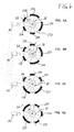
- the arithmetic unit 30 is in the FIGS. 1 and 2 drawn as a module, but according to one embodiment, the arithmetic unit 30 is physically distributed to a plurality of modules and / or electronic circuits.
- the embodiment of a device for detecting a first angle of rotation of a first shaft 10 of a motor has a first marking carrier 110 with sensor-readable markings, which in FIG. 1 by way of example as teeth 133, 134, 135, 136, 137, these markings 133 to 137 forming a first marking pattern.
- the first marking pattern comprises a plurality of marking sections, each of which has at least one tooth 133 to 137 in the exemplary embodiment.
- the first marking carrier 110 is set in a rotational movement by the first shaft 10, wherein the rotation of the first shaft 10 runs by way of example in the clockwise direction, which is indicated by the curved arrow 138 on the first shaft 10.
- the rotational angle of the first shaft 10 and the rotational angle of the first marker carrier 110 are identical.
- the first marking carrier 110 is scanned and the first sensor 141 generates a first sensor signal 151 during the scanning, wherein the first sensor signal 151 is modulated on the first marking carrier 110 by means of the markings 133 to 137.
- the sensor signal input 320 is provided as an interface of the arithmetic unit and configured to take over the first sensor signal 151 of the first sensor 141 into the arithmetic unit 30.
- the forwarding of the information provided by the first sensor 141 to the information-processing components (not completely shown) of the arithmetic unit 30 takes place from the sensor signal input 320.
- the arithmetic unit 30 assigns the first sensor signal 151 to the time signal (not shown). of the timer 330.
- Arithmetic unit 30 shown schematically has a memory unit 310 with a memory area 311 with stored marker sections, comprising at least a first stored marker section and a second stored marker section.
- the arithmetic unit 30 has a sensor signal input 320 and a timer 330 with a time signal.
- the time signal of the timer 330 is preferably available within the arithmetic unit in order that the first sensor signal 151, which is modulated by the markings 133 to 137 of the first marking carrier 110, in the course of the scanning of the first marking carrier 110, each current time information within the arithmetic unit 30th is assigned.
- Arithmetic unit 30 allows an assignment of the time interval to the angle, which is covered in the time interval of the first mark carrier 110 or was.
- the arithmetic unit 30 preferably has a compression unit 350.
- the compression unit 350 fulfills the task of at least partially eliminating redundant information adhered to the stored tag portions at the time of detection.
- a further function of the compression unit is preferably to eliminate, at least partially, redundant or superfluous information that arises during the scanning of the first mark carrier 110 by means of the first sensor 141 and possibly during the assignment of the time signal to the first sensor signal 151.
- both the stored marking portions and the recovered marking portions of the first marking carrier 110 are used in compressed form in carrying out the method according to the invention. For example, as in FIG.
- the first marker carrier 110 is designed as a gear with only two types of markers, namely small teeth 133, 134, 135 and large teeth 136, 137, it may be sufficient for the determination of the first and the further exclusion criteria, that by means of the first sensor 141 and the associated processing unit 30 is determined during the rotation of the first mark carrier 110, whether at a certain time a small tooth or a large tooth was scanned.
- the direction of rotation of the first shaft 10 is indicated in this example by the curved arrow 138, which is drawn above the first shaft.
- the temporal scanning order of the following teeth in FIG. 3 can be concluded on the rotation angle of the first wave: small tooth, small tooth, large tooth. The end of this scanning order is in the example according to FIG FIG.
- the compression unit 350 is implemented within an FPGA device.
- the inventive method assumes that the arithmetic unit 30 has a memory unit 310 with a memory area 311, wherein the stored information of the memory area 311 in particular the, in FIG. 1 not shown, stored marking sections include.
- one of the following two functions for providing the stored marking sections in the memory area 311 of the arithmetic unit 30 is carried out by means of the arithmetic unit before the method according to the invention is carried out:
- the first function provides that the first marker carrier 110 at a predefined angular velocity in a predefined direction of rotation is driven by the first shaft and at the same time by means of the first sensor and the arithmetic unit a signal-time characteristic or a signal-angle characteristic of the first mark carrier is scanned and "written".
- the second function for providing the stored marker pattern provides that an interface 340 of the arithmetic unit 30 is provided, and the data from a further external data source, which is not shown in the figures, or by manual input by the user via the interface 340 the memory unit 310 is transmitted to the arithmetic unit 30, which data form the stored marker pattern.
- a first marking section is retrieved from the first sensor signal 151 by means of the arithmetic unit 30, and subsequently from the recovered first marking section a first exclusion criterion for excluding the first stored marking section (in FIG FIG. 1 not shown). Subsequently, the first stored marking section is excluded by means of the first exclusion criterion. Thereafter, it is checked whether a difference of a total number of the stored marker portions minus a number of excluded stored marker portions is equal to one, and proceeding to the step of deriving the first rotation angle from the non-excluded stored marker portion if the difference is equal to 1 is.
- a further advantage of the method is that preferably no complete revolution of the first shaft 10 or of the first marking carrier 110 is necessary in order to determine the angle of rotation of the first shaft 10 or of the first marking carrier 110 after an initialization process.
- start-stop automatic is in particular the task to achieve a comparatively timely detection of the angle of rotation of the crankshaft for the purpose of reducing fuel consumption at each start-up process.
- the method according to the invention offers in this exemplary field of application an advantageous solution which requires comparatively cost-effective circuit complexity.
- a further advantage of the method is the flexibility of the solution according to the invention, in particular for development and test system manufacturers, in that the method is easily adaptable to various marking carriers.
- the rotational angles of crankshafts of engines can preferably be detected with one and the same device, the crankshafts of the different engines having different types of marking carriers.
- the method according to the invention can also be used in a virtual environment in the context of a runtime simulation of a virtual motor with virtual components and consequently also a virtual marking carrier and a virtual sensor.
- a second arithmetic unit which acts a simulation model of the engine with a sensor maps and with an input-output circuitry together.
- the modulated signal of the sensor is provided by the input-output circuitry so that the output of the simulated first sensor corresponds to the output of a real first sensor 141.
- the picture of the FIG. 2 shows that, in addition to the first sensor signal 151, a second sensor signal for the arithmetic unit is preferably provided.
- the second sensor signal 241 is obtained by scanning a preferably rotating second marking carrier 210 - presently shown as a rotating cam of a camshaft 20 - by a second sensor 241, which is preferably an inductive proximity switch. With a predefined approach of the cam to the second sensor 241, the second sensor signal 245 changes.
- the time signal of the timer 330 preferably assigns time information to the second sensor signal, in particular the flanks of the second sensor signal from the arithmetic unit 30.
- An advantage is that when assigning the first mark carrier with a first mark pattern to a crankshaft and an assignment of the second mark carrier with a second mark pattern to a camshaft, a determination of the number of the clock of a four-stroke engine, especially after the engine stops or immediately during the starting process of the engine.
- a determination of the number of the clock of a four-stroke engine especially after the engine stops or immediately during the starting process of the engine.
- the second mark carrier which is preferably designed as a cam of the camshaft, and is offset by the camshaft in a rotational movement, can be by means of the second sensor preferably after the initialization of the control device of the engine, for example after Activate the starting process, eg.
- the second rotation angle of the second wave By ignition key or start button, based on the position of the second mark carrier, the second rotation angle of the second wave and thus preferably determine the clock of the four-stroke engine or exclude at least one or more cycles.
- the fastest possible determination of the clocks of the cylinder of a multi-cylinder four-stroke internal combustion engine can be achieved by assigning a sensor to each cam of the camshaft, because after sampling a cam can be closed at least approximately for all cylinders to the clock of the respective cylinder in the rule .
- the rotation angle determination by sampling the cams of a camshaft taken alone for the purposes of the control of the internal combustion engine is usually not sufficient, for example, because the achievable accuracy of the rotation angle determination via cam scanning is not sufficient for a consumption-optimized control (with respect to fuel consumption) of the internal combustion engine.
- the scanning of the cam or by means of the second sensor or by means of further sensors is preferably only a limitation of an interval of the rotation angle of the first shaft, for example, to determine a cylinder stroke
- the "size" of a tooth in the context of the invention means the angle of rotation of the toothed wheel represented by this tooth.
- FIG. 3 is configured as a gear first marker carrier 10 equipped with a total of 5 teeth, the tooth gaps between the teeth always represent an equal angular width namely 30 degrees.
- a marking portion is exactly one tooth at a time, and two types of teeth are provided, namely, 30-degree teeth and 60-degree teeth. All concrete angle values in this text are given in degrees, ie the full angle is 360 degrees.
- a marking carrier 110 has a first tooth 133, a second tooth 134, a third tooth 135, wherein these three teeth each represent an angular width of 30 degrees.
- the marker carrier further includes a fourth tooth 136 and a fifth tooth 137, each of the latter teeth representing an angular width of 60 degrees each.
- Each tooth is followed by a tooth gap, which represents an angle of 30 degrees each.
- the angle of rotation of the shaft results from the addition of the angular distances of the teeth and tooth spaces scanned by the first sensor.
- first and / or second sensor 141, 241 may be configured such that only the information about scanned tooth starts or transmitted only via scanned tooth ends from the first sensor to the arithmetic unit.
- each tooth beginning and each tooth end is scanned by the first sensor and transmitted to the arithmetic unit essentially without a time delay to be considered.
- the marker carrier 110 is provided and configured to rotate in the rotational direction indicated by the curved arrow 138. During the rotation of the marking carrier, all teeth are successively guided along the first sensor 141 in succession per full revolution. By means of the first sensor 141 tooth starts and tooth ends of all teeth of the marking carrier 110 are scanned.
- the angular velocity of the first shaft 110 is assumed to be constant in this example.
- the value of the angular velocity is stored in the arithmetic unit.
- FIG. 4 the connection between the first sensor 141 and sensor signal input 320 of the arithmetic unit 30 is not shown. It goes without saying, however, that the first sensor signal 151 emanating from the first sensor 141 is connected to a computing unit 30 as shown in FIGS FIGS. 1 and 2 is shown, must be forwarded so that by means of evaluation of the first sensor signal 151 from the arithmetic unit 30, a rotation angle of the first mark carrier 110 and thus a rotation angle of the first shaft 10 can be determined.
- the angular velocity of the first shaft 110 is substantially constant and the value of the angular velocity is stored in the arithmetic unit.
- time delays resulting from the signal processing can be disregarded, in particular those time delays which occur during signal generation by means of the first sensor 141, signal forwarding of the first sensor signal 151 to the arithmetic unit 30 and signal evaluation of the signal first sensor signal 151 within the arithmetic unit 30 arise.
- FIG. 4 is an embodiment of a first mark carrier 110 in successive snapshots according to the FIG. 4 belonging Detail- FIGS. 4A to 4D shown in a preferred sequence of individual phases of the detection of the rotational angle of the first shaft 10.
- the first marking carrier shown here is preferably identical to the first marking carrier 110 according to the exemplary embodiment in FIG. 3 ,
- the stored marker sections in this embodiment have stored representations of sequences of successive tooth types, here sequences of short teeth and / or long teeth.
- An exclusion criterion for stored marking sections is formed.
- the total number of stored marker sections comprises in the exemplary embodiment stored representations of all scanning sequences which are technically possible in the present first marker carrier, the present rotational direction according to arrow 138 and the associated arrangement of the first sensor 141.
- the difference between the total number of the stored marker portions minus the number of the excluded marker portions excluded is according to the moment of the snapshot FIG. 4B greater one.
- the scan of the mark carrier 110 must be continued to determine its rotation angle.
- the arithmetic unit 30 stores the "scan history" preferably from the initialization process, ie the order and type of already scanned teeth, preferably from the last scanned tooth up to the tooth, at the total number of teeth of the first mark carrier 110 is reached.
- the "types" of teeth are in the embodiment according to FIG. 4 the “long” teeth 136, 137 and the “short” teeth 133, 134, 135 to understand.
- the third tooth 135 is scanned in the snapshot shown.
- the arithmetic unit 30 in which the stored sampling history is present, all marking sections are excluded, which do not begin with two short teeth in succession. Nevertheless, the difference between the total number of stored marker sections minus the number of excluded marker sections is still greater than one. The scan of the mark carrier 110 must be continued to determine its rotation angle.
- Out Figure 4D shows that by means of the first sensor 141, the scanning of the fourth tooth 136 is completed.
- the following scanning history is stored in the memory unit 310 of the arithmetic unit 30 in the following order: short tooth, short tooth, long tooth.
Abstract
Description
Die Erfindung betrifft ein Verfahren zur Erfassung eines Drehwinkels gemäß dem Oberbegriff des Patentanspruchs 1.The invention relates to a method for detecting a rotation angle according to the preamble of patent claim 1.
Aus der freien Internet-Enzyklopädie WIKIPEDIA ist ein Rotations-Encoder bekannt, der mit einer Welle eines Motors verbunden werden könnte. Der Encoder bietet die Möglichkeit, einen Drehwinkel, der in Sektoren eingeteilt ist, festzustellen. Hierbei könnte vorgesehen sein, konzentrisch angeordnete Sektor-Bereiche eines Kreissektors einer kreisförmigen Encoder-Scheibe von mehreren Sensoren zeitgleich abzutasten. Nachteile an dem Rotations-Encoder sind insbesondere, dass einerseits zwingend mehrere Sensoren erforderlich sind und andererseits die Anordnung von Encoder-Scheibe und zugehörigen Sensoren einen hohen konstruktiven Aufwand erfordert, insbesondere bezüglich der Einhaltung der Fertigungstoleranzen, die von der geforderten maximal zulässigen Drehwinkel-Messabweichung des Encodersystems abhängt.From the free Internet encyclopedia WIKIPEDIA a rotary encoder is known, which could be connected to a shaft of an engine. The encoder offers the possibility to determine a rotation angle, which is divided into sectors. In this case, it would be possible to scan concentrically arranged sector regions of a circular sector of a circular encoder disk of several sensors at the same time. Disadvantages of the rotary encoder are in particular that on the one hand necessarily several sensors are required and on the other hand the arrangement of encoder disc and associated sensors requires a high design effort, in particular with regard to compliance with the manufacturing tolerances of the required maximum allowable rotation angle error of the Encoder system depends.
Aus dem Dokument "
Vor diesem Hintergrund besteht die Aufgabe der Erfindung darin, ein Verfahren anzugeben, das den Stand der Technik weiterbildet.Against this background, the object of the invention is to provide a method which further develops the prior art.
Die Aufgabe wird durch ein Verfahren mit den Merkmalen des Patentanspruchs 1 gelöst. Vorteilhafte Ausgestaltungen der Erfindung sind Gegenstand von abhängigen Ansprüchen.The object is achieved by a method having the features of patent claim 1. Advantageous embodiments of the invention are the subject of dependent claims.
Gemäß dem Gegenstand der Erfindung wird ein Verfahren zur Erfassung eines ersten Drehwinkels einer ersten Welle eines Motors bereitgestellt, wobei
- ein erster Markierungsträger mit sensorlesbaren Markierungen vorgesehen ist, wobei die Markierungen ein erstes Markierungsmuster ausbilden,
- das erste Markierungsmuster Markierungsabschnitte, umfassend zumindest einen ersten Markierungsabschnitt und einen zweiten Markierungsabschnitt, aufweist,
- der erste Markierungsträger von der ersten Welle in eine Rotationsbewegung versetzt wird,
- und eine Proportionalität zwischen dem Drehwinkel der ersten Welle und dem Drehwinkel des ersten Markierungsträgers besteht,
eine Recheneinheit vorgesehen ist, aufweisend
- eine Speichereinheit mit einem Speicherbereich mit gespeicherten Markierungsabschnitten, umfassend zumindest einen ersten gespeicherten Markierungsabschnitt und einen zweiten gespeicherten Markierungsabschnitt,
- einen Sensorsignal-Eingang,
- einen Zeitgeber mit einem Zeitsignal,
- a) ein erster Markierungsabschnitt wird aus dem ersten Sensorsignal zurück gewonnen, und nachfolgend
- b) aus dem zurückgewonnenen ersten Markierungsabschnitt wird ein erstes Ausschlusskriterium zum Ausschließen des ersten gespeicherten Markierungsabschnittes ermittelt, und nachfolgend
- c) mittels des ersten Ausschlusskriteriums wird zumindest der erste gespeicherte Markierungsabschnitt ausgeschlossen, und nachfolgend
- d) es wird überprüft, ob eine Differenz einer Gesamtanzahl der gespeicherter Markierungsabschnitte abzüglich einer Anzahl ausgeschlossener gespeicherter Markierungsabschnitte gleich eins ist und es wird übergegangen zu Verfahrensschritt g) falls die Differenz gleich 1 ist, es wird übergegangen zu Verfahrensschritt e) falls die Differenz größer eins ist,
- e) es wird ein weiterer Markierungsabschnitt aus dem ersten Sensorsignal zurück gewonnen, es wird ein weiteres Ausschlusskriterium ermittelt, es wird mittels des weiteren Ausschlusskriteriums ein weiterer gespeicherter Markierungsabschnitt ausgeschlossen, und nachfolgend
- f) der Verfahrensschritt d) wird erneut ausgeführt,
- g) aus dem nicht ausgeschlossenen gespeicherten Markierungsabschnitt wird der erste Drehwinkel abgeleitet.
- a first marking carrier with sensor-readable markings is provided, wherein the markings form a first marking pattern,
- the first marking pattern has marking sections comprising at least a first marking section and a second marking section,
- the first marking carrier is set in a rotational movement by the first shaft,
- and there is a proportionality between the angle of rotation of the first shaft and the angle of rotation of the first marking carrier,
an arithmetic unit is provided, comprising
- a storage unit having a storage area with stored marking sections, comprising at least a first stored marking section and a second stored marking section,
- a sensor signal input,
- a timer with a time signal,
- a) a first marking portion is recovered from the first sensor signal, and subsequently
- b) from the recovered first marker portion, a first exclusion criterion for excluding the first stored marker portion is determined, and subsequently
- c) by means of the first exclusion criterion, at least the first stored marking section is excluded, and subsequently
- d) it is checked whether a difference of a total number of the stored tag portions minus a number of excluded tagged tag portions is equal to one and it goes to step g) if the difference is equal to 1, it goes to step e) if the difference is greater than one is
- e) a further marking section is recovered from the first sensor signal, a further exclusion criterion is determined, a further stored marking section is excluded by means of the further exclusion criterion, and subsequently
- f) the process step d) is carried out again,
- g) from the not excluded stored marking portion of the first rotation angle is derived.
Im Einzelnen gibt es eine Vielzahl von Möglichkeiten, das erfindungsgemäße Verfahren auszugestalten und weiterzubilden. Dazu wird verwiesen einerseits auf die dem Patentanspruch 1 nachgeordneten Patentansprüche, andererseits auf die folgende Beschreibung in Verbindung mit den Zeichnungen.In particular, there are a large number of possibilities for designing and developing the method according to the invention. Reference is made on the one hand to the claims subordinate to claim 1, on the other hand to the following description in conjunction with the drawings.
Es sei angemerkt, dass die Abtastung des ersten Markierungsträgers mittels des ersten Sensors sequentiell durchgeführt wird, und dass während der Abtastung der Markierungsabschnitte des ersten Markierungsträgers bevorzugt Zeitinformationen des Zeitsignals dem Sensorsignal des ersten Sensors mittels der Recheneinheit zugeordnet werden. Da in einer bevorzugten Ausführungsform zumindest für einen Teil einer Umdrehung die Winkelgeschwindigkeit der ersten Welle bekannt oder abschätzbar ist und näherungsweise als konstant anzusehen ist, ergibt sich aus der Berechnungsvorschrift für die zumindest näherungsweise konstante Winkelgeschwindigkeit ω, dass diese sich als Quotient, Drehwinkeländerung Δφ geteilt durch Zeitänderung Δt, berechnet: ![]()
![]()
Folglich kann für den Teil der Umdrehung der ersten Welle, in dem die Winkelgeschwindigkeit zumindest näherungsweise bekannt und näherungsweise konstant ist, aus einer Zeitänderung direkt auf die Winkeländerung geschlossen werden: ![]()
![]()
Es ist desweiteren bevorzugt, dass mittels der Recheneinheit nach jedem Abtasten einer Markierung oder eines Markierungsabschnittes des ersten Markierungsträgers mittels des ersten Sensors die Winkelgeschwindigkeit aktualisiert wird.It is furthermore preferred that the angular velocity is updated by means of the arithmetic unit after each scanning of a marking or a marking section of the first marking carrier by means of the first sensor.
Es sei desweiteren angemerkt, dass es gemäß einer beispielhaften Ausgestaltung des ersten Markierungsträgers vorgesehen ist, gleichartig gestaltete Markierungen bzw. gleichartig gestaltete Markierungsabschnitte mehrfach in den ersten Markierungsträger zu integrieren. Am Beispiel eines als Zahnrad ausgestalteten ersten Markierungsträgers wird dies in einem der letzten Abschnitte der Beschreibung unter Bezugnahme auf die Figuren anschaulich beschrieben, siehe insbesondere Figurenbeschreibung zu
Eine vollständige Abtastung aller Markierungsabschnitte des ersten Markierungsträgers ist mittels des ersten Sensors nur dann ermöglicht, wenn der erste Markierungsträger zumindest eine vollständige Umdrehung ausführt, und während der vollständigen Umdrehung alle Markierungsabschnitte des ersten Markierungsträgers den ersten Sensor passieren. Einer der Vorteile der Erfindung ist aber, dass zur Feststellung des Drehwinkels der ersten Welle nicht der gesamte Markierungsträger abgetastet werden muss.A complete scanning of all marking sections of the first marking carrier is made possible by means of the first sensor only if the first marking carrier performs at least one complete revolution, and during the complete revolution all marking sections of the first marking carrier pass the first sensor. However, one of the advantages of the invention is that not the entire marking carrier has to be scanned in order to determine the angle of rotation of the first shaft.
Anhand des folgenden Ausführungsbeispiels soll der Vorgang des Abtastens des ersten Markierungsträgers näher erläutert werden. Gemäß einer Ausgestaltungsform der Erfindung ist der erste Markierungsträger ein Zahnrad mit metallischen Zähnen und der erste Sensor ein induktiver Näherungsschalter, wobei die Zähne des metallischen Zahnrades während der Rotation nacheinander an dem induktiven Näherungsschalter entlanggeführt werden, damit mit dem induktiven Näherungsschalter die Zähne und/oder die Grenzflächen, an denen die Zähne beginnen oder enden, erfasst werden. Im Zuge der Abtastung des ersten Markierungsabschnittes erfolgt mittels der Recheneinheit eine Zuordnung zwischen dem von dem ersten Sensor erfassten ersten Markierungsabschnitt und dem Erfassungszeitpunkt und der Erfassungsdauer des ersten Markierungsabschnittes mittels des Zeitsignals.
Wenn die Markierungen bzw. die Markierungsabschnitte eines Markierungsträgers in den Wirkungsbereich eines Sensors gebracht werden, so dass der Sensor die Markierungen bzw. Markierungsabschnitte abtastet, so spricht man davon, dass die Markierungen bzw. Markierungsabschnitte den Sensor passieren.Reference to the following embodiment, the process of scanning the first mark carrier will be explained in more detail. According to one embodiment of the invention, the first marking carrier is a gear with metallic teeth and the first sensor is an inductive proximity switch, wherein the teeth of the metallic gear are guided along the inductive proximity switch during rotation successively, so that the inductive proximity switch teeth and / or Boundary surfaces at which the teeth begin or end are detected. In the course of scanning the first marking section, the arithmetic unit makes an association between the first marking section detected by the first sensor and the detection time and the detection duration of the first marking section by means of the time signal.
If the markings or the marking sections of a marking carrier are brought into the region of action of a sensor, so that the sensor scans the markings or marking sections, it is said that the markings or marking sections pass through the sensor.
Aus den bei der Erfassung eines ersten Markierungsabschnittes gewonnenen Daten ist es der Recheneinheit ermöglicht, zumindest einen ersten gespeicherten Markierungsabschnitt auszuschließen, und zwar den bzw. die gespeicherten Markierungsabschnitt bzw. Markierungsabschnitte, der bzw. die einer gespeicherten Beschreibung, die als gespeicherter Markierungsabschnitt oder als Markierungsabschnitts-Beschreibung bezeichnet wird, nicht entspricht bzw. nicht entsprechen. Der Begriff "Markierungsabschnitts-Beschreibung" ist also in dem oben genannten Zusammenhang derart auszulegen, dass ein n-ter Markierungsabschnitt des ersten Markierungsträgers durch eine n-te gespeicherte Datenmenge Mn charakterisiert ist, die von dem ersten Sensor abtastbaren technische Merkmale oder von diesen technischen Merkmalen abgeleitete Merkmale des n-ten Markierungsabschnittes des ersten Markierungsträgers umfasst, wobei n = 1, 2, ... m, und wobei m = Anzahl der Markierungsabschnitte des ersten Markierungsträgers.
Die Datenmenge Mn ist im Speicherbereich der Recheneinheit abgelegt.From the data obtained upon detection of a first marker portion, the arithmetic unit is enabled to exclude at least a first stored marker portion, namely the stored marker portion (s) of a stored description serving as a stored marker portion or as a marker portion Description called is, does not correspond or does not correspond. The term "marking portion description" is thus interpreted in the above context such that an n-th marking portion of the first mark carrier is characterized by an n-th stored amount of data Mn, the technical characteristics scannable by the first sensor or of these technical features derived features of the n-th marking portion of the first mark carrier, wherein n = 1, 2, ... m, and where m = number of the marking portions of the first mark carrier.
The data set Mn is stored in the memory area of the arithmetic unit.
Die Gesamtheit aller Markierungsabschnitts-Beschreibungen des ersten Markierungsträgers bildet die Markierungsträger-Beschreibung des ersten Markierungsträgers. Vorzugsweise sind alle Markierungsabschnitts-Beschreibungen des ersten Markierungsträgers in der Recheneinheit gespeichert. Mit anderen Worten bildet bevorzugt die Gesamtheit aller gespeicherten Markierungsabschnitte des ersten Markierungsträgers den ersten gespeicherten Markierungsträger. Somit ist eine gespeicherte Beschreibung eines n-ten Markierungsabschnitts gleichzusetzen mit einem n-ten gespeicherten Markierungsabschnitt. Dieser n-te gespeicherter Markierungsabschnitt umfasst bevorzugt in kodierter Form eine Signal-Zeit-Charakteristik oder eine Signal-Winkel-Charakteristik des n-ten Markierungsabschnittes auf dem ersten Markierungsträger.The entirety of all tag portion descriptions of the first tag carrier form the tag carrier description of the first tag carrier. Preferably, all of the tag portion descriptions of the first tag carrier are stored in the arithmetic unit. In other words, the entirety of all stored marking sections of the first marking carrier preferably forms the first stored marking carrier. Thus, a stored description of an nth mark portion is to be equated with an nth stored mark portion. This nth stored marking section preferably comprises in coded form a signal-time characteristic or a signal-angle characteristic of the n-th marking section on the first marking carrier.
Bevorzugt weist die Signal-Zeit-Charakteristik des n-ten gespeicherten Markierungsabschnitts ein gespeichertes Zeitintervall auf, und dieses gespeicherte Zeitintervall ist ein Maß für die Abtastdauer, in der ein Markierungsabschnitt von dem ersten Sensor abgetastet wird, wenn der erste Markierungsträger mit einer vordefinierten Winkelgeschwindigkeit rotiert und der n-te Markierungsabschnitt den Sensor passiert.Preferably, the signal-time characteristic of the nth stored tag portion has a stored time interval, and this stored time interval is a measure of the sample duration in which a tag portion is scanned by the first sensor as the first tag carrier rotates at a predefined angular velocity and the nth marking section passes the sensor.
Zur Erläuterung ist nachfolgend ein Beispiel angeführt, bei dem ein erster Markierungsabschnitt aus nur einer einzigen Markierung - beispielsweise aus einem Zahn - besteht. In diesem Beispiel ist folglich der erste Markierungsabschnitt mit der ersten Markierung gleichzusetzen.
Bevorzugt werden von der Recheneinheit Abweichungen, die mittels der Recheneinheit bei dem Vergleich zwischen einer gespeicherten n-ten Markierung und einer abgetasteten n-ten Markierung festgestellt werden, im Umfang eines vordefinierten Toleranzbereiches von der Recheneinheit akzeptiert, das heißt, eine n-te Markierung wird bevorzugt trotz einer Abtastzeit-Abweichung der zugehörigen gespeichert n-ten Markierung zugeordnet, solange die Abweichung innerhalb eines vordefinierten Toleranzbereiches liegt. Trotz einer Abweichung eines abgetasteten Wertes von einem vordefinierten "nominellen" Wert, wird der abgetastete Wert von der Recheneinheit als zulässig deklariert, solange der abgetastete Wert im Toleranzbereich des "nominellen" Wertes liegt.
Beispielsweise können die Toleranzbereiche für eine Erweiterung des Wertebereichs einer in der Recheneinheit gespeicherten Markierung vorgesehen sein. In dem Beispiel ist eine erste gespeicherte Markierung durch eine "nominelle" erste Abtastzeit Δt1 bei einer vorzugsweise konstanten ersten Winkelgeschwindigkeit ω1 definiert. Um die "nominelle" Abtastzeit wird in diesem Beispiel ein Toleranzbereich geschaffen, indem einerseits für den Minimalwert des Toleranzbereiches die "nominelle" Abtastzeit um einen Toleranzzeitwert ΔtT verringert wird, und
andererseits für den Maximalwert des Toleranzbereiches die "nominelle" Abtastzeit um einen Toleranzwert ΔtT vergrößert wird.
Ist beispielsweise die erste Abtastzeit Δt1 = 1 ms und derFor explanation, an example is given below, in which a first marking section consists of only a single marking - for example, a tooth. In this example, therefore, the first marking section is to be equated with the first marking.
Deviations, which are determined by means of the arithmetic unit in the comparison between a stored nth mark and a scanned nth mark, are preferably accepted by the arithmetic unit within the scope of a predefined tolerance range, that is, an nth mark preferred despite a sampling time deviation of the associated stored n-th mark assigned as long as the deviation is within a predefined tolerance range. Despite a deviation of a sampled value from a predefined "nominal" value, the sampled value is declared as allowable by the arithmetic unit as long as the sampled value is within the tolerance range of the "nominal" value.
For example, the tolerance ranges can be provided for an extension of the value range of a marker stored in the arithmetic unit. In the example, a first stored marker is defined by a "nominal" first scan time Δt 1 at a preferably constant first angular velocity ω 1 . In this example, a tolerance range is created around the "nominal" sampling time by, on the one hand, reducing the "nominal" sampling time by a tolerance time value Δt T for the minimum value of the tolerance range, and
on the other hand, for the maximum value of the tolerance range, the "nominal" sampling time is increased by a tolerance value Δt T.
For example, if the first sampling time Δt 1 = 1 ms and the
Toleranzzeitwert ΔtT = 0,2 ms, so ergibt sich in dem Beispiel für die minimale erste Abtastzeit: ![]()
![]()
Außerdem ergibt sich für die maximale erste Abtastzeit: ![]()
was für dieses Beispiel bedeutet, dass die erste Abtastzeit des ersten gespeicherten Markierungsträgers bei der ersten Winkelgeschwindigkeit ω1 zwischen 0,8 ms und 2,2 ms liegt. Wenn in diesem Beispiel mittels der Recheneinheit ein gespeicherter ersten Markierungsabschnitt mit einem zurückgewonnenen Markierungsabschnitt verglichen wird, und bei diesem Vergleich festgestellt wird, dass bei einer ersten Winkelgeschwindigkeit ω1 die gemessene Abtastzeit des zurückgewonnenen Markierungsabschnittes zwischen den Toleranzgrenzen Δt1min und Δt1max liegt, dann ordnet die Recheneinheit der gemessenen Abtastzeit den Wert Δt1 zu, der charakteristisch für einen Markierungsabschnitt bzw. für einen Typ eines Markierungsabschnittes ist, beispielsweise ein kurzer Zahn oder ein langer Zahn eines abgetasteten Zahnrades. Andere Markierungsabschnitte, die bei der ersten Winkelgeschwindigkeit ω1 eine Abtastzeit aufweisen, die nicht zwischen den Toleranzgrenzen Δt1min und Δt1max liegt, können ausgeschlossen werden. Es liegt für den Fachmann auf der Hand, dass sich die Abtastzeiten für ein und denselben Markierungsabschnitt verkürzen, wenn die Winkelgeschwindigkeit und damit die Drehzahl des rotierenden Markierungsträgers ansteigen.In addition, for the maximum first sampling time: ![]()
which means for this example that the first sampling time of the first stored mark carrier at the first angular velocity ω 1 is between 0.8 ms and 2.2 ms. In this example, when a stored first mark portion is compared with a retrieved mark portion by the arithmetic unit and it is found in this comparison that the measured sampling time of the retrieved mark portion is between the tolerance limits Δt 1min and Δt 1max at a first angular velocity ω1, then Calculated unit of the measured sampling the value .DELTA.t 1 , which is characteristic of a marking portion or for a type of a marking portion, for example, a short tooth or a long tooth of a scanned gear. Other marking sections which have a sampling time at the first angular velocity ω 1 which does not lie between the tolerance limits Δt 1min and Δt 1max can be excluded. It is obvious to those skilled in the art that the sampling times for one and the same marking section shorten as the angular velocity and thus the rotational speed of the rotating marking carrier increase.
Besonders bevorzugt erfolgt mittels der Recheneinheit eine Anpassung des Toleranzbereichs an die Drehzahl der ersten Welle oder an die Winkelbeschleunigung der ersten Welle oder - soweit von der Recheneinheit der Drehwinkel der ersten Welle zu einem Zeitpunkt-X zumindest annähernd bestimmbar ist - an die Position der Welle zum Zeitpunkt-X, das heißt, der Toleranzbereich ist bevorzugt kein konstanter Bereich, sondern dessen Bereichsgrenzen sind bevorzugt eine Funktion der Drehzahl oder eine Funktion der Winkelbeschleunigung oder eine Funktion der Wellenposition, also des Drehwinkels der ersten Welle. Ein Vorteil der Anpassung des Toleranzbereiches an die Wellenposition der ersten Welle kann beispielsweise bei einem Verbrennungsmotor insbesondere dann hervortreten, wenn der Toleranzbereich in einem vordefinierten Drehwinkel-Intervall der Kurbelwelle eines 4-Takt-Ottomotors oder eines 4-Takt-Dieselmotors vorgenommen wird, und beispielsweise in dem Drehwinkel-Bereich von einigen Grad ab dem oberen Totpunkt im dritten Takt des 4-Takt-Motors (Takt der mit der Zündung beginnt) der Toleranzbereich vergrößert wird. Diese Vergrößerung kann vorteilhaft sein, weil in dem dritten Takt, also nach der Zündung - beispielsweise bei Motoren mit einem oder zwei Zylinder/n - mit einer ansteigenden Drehzahl zu rechnen ist. Ähnliches gilt bevorzugt für Motoren mit vier bis sechs Zylindern, die eine leistungsabhängige Zylinderabschaltung aufweisen.Particularly preferably, by means of the arithmetic unit, an adaptation of the tolerance range to the rotational speed of the first shaft or to the angular acceleration of the first shaft or - as far as the arithmetic unit of the rotation angle of the first wave at a time-X is at least approximately determinable - to the position of the shaft to Time-X, that is, the tolerance range is preferably not a constant range, but whose range limits are preferably a function of the rotational speed or a function of the angular acceleration or a function of the shaft position, ie the rotation angle of the first shaft. An advantage of the adaptation of the tolerance range to the shaft position of the first shaft can emerge, for example, in an internal combustion engine, in particular when the tolerance range is set in a predefined rotational angle interval of the crankshaft of a 4-stroke gasoline engine or a 4-stroke diesel engine, and for example is increased in the rotation angle range of several degrees from top dead center in the third clock of the 4-stroke engine (clock starts with the ignition) of the tolerance range. This increase can be advantageous because in the third cycle, ie after the ignition - for example, in engines with one or two cylinders / n - is to be expected with an increasing speed. The same applies preferably to engines with four to six cylinders, which have a power-dependent cylinder deactivation.
Die Signal-Winkel-Charakteristik weist eine oder mehrere Winkelintervall/e auf, wobei innerhalb des Winkelintervalls oder der Winkelintervalle eine vordefinierte Information des ersten Sensorsignals abtastbar ist, soweit ein vordefinierter Winkelgeschwindigkeitsbereich und/oder ein bestimmter Winkelbeschleunigungsbereich der ersten Welle weder unterschritten noch überschritten wird.The signal-angle characteristic has one or more angular intervals, wherein predefined information of the first sensor signal can be scanned within the angular interval or the angular intervals, as far as a predefined angular velocity range and / or a specific angular acceleration range of the first wave is neither exceeded nor exceeded.
Mittels der Recheneinheit ist bevorzugt eine Signal-Zeit-Charakteristik in eine Signal-Winkel-Charakteristik oder umgekehrt umwandelbar.By means of the arithmetic unit is preferably a signal-time characteristic in a signal-angle characteristic or vice versa convertible.
Bevorzugt werden die Winkelintervalle, die den Sensorsignalen gemäß einer Weiterbildung der Erfindung zugeordnet werden, von einer sogenannten Winkel-Uhr bereitgestellt, die bevorzugt in der Recheneinheit implementiert ist. Mittels der Winkel-Uhr werden zyklisch aktuelle Winkelwerte oder Winkelintervalle des rotierenden Markierungsträgers bezogen auf einen vordefinierten Null-Grad-Wert berechnet, wobei bevorzugt das Zeitsignal des Zeitgebers der Recheneinheit und/oder eine Winkelgeschwindigkeit und/oder eine Winkelbeschleunigung als Eingangsvariablen der Winkeluhr dienen. Mittels der Winkel-Uhr wird ein Winkel-Uhr-Ausgabewert erzeugt, der dann für weitere Berechnungen der Recheneinheit zur Verfügung steht.Preferably, the angular intervals, which are assigned to the sensor signals according to an embodiment of the invention, provided by a so-called angle clock, which is preferably implemented in the arithmetic unit. The angle clock cyclically calculates current angle values or angular intervals of the rotating marking carrier relative to a predefined zero-degree value, the time signal of the timer of the arithmetic unit and / or an angular velocity and / or an angular acceleration preferably serving as input variables of the angular clock. through The angle clock is an angle-clock output value generated, which is then available for further calculations of the arithmetic unit.
Wird beispielsweise mittels des ersten Sensors ein n-ter Markierungsabschnitt des ersten Markierungsträgers abgetastet, ist mittels der Winkel-Uhr eine Zuordnung des n-ten Markierungsabschnittes zu einer Drehwinkel-Differenz ermöglicht, wobei diese Drehwinkel-Differenz die Differenz des Drehwinkels am Ende des n-ten Markierungsabschnittes abzüglich des Drehwinkels am Anfang des n-ten Markierungsabschnittes ist. Der Betrag dieser Differenz repräsentiert die Größe des Bereichs, der von dem n-ten Markierungsabschnitt eingenommenen wird, oder anders gesagt, die Größe des n-ten Markierungsabschnittes.If, for example, an nth marking section of the first marking carrier is scanned by means of the first sensor, an assignment of the nth marking section to a rotational angle difference is made possible by means of the angle clock, this rotational angle difference representing the difference of the rotational angle at the end of the n-th marking section. th marking portion minus the rotation angle at the beginning of the n-th marking section. The amount of this difference represents the size of the area occupied by the nth mark portion, or in other words, the size of the nth mark portion.
Am Beispiel eines ersten Markierungsträgers der bevorzugt als ein Zahnrad ausgestaltet ist, soll das im vorherigen Textabschnitt beschriebene Ausführungsbeispiel der Ermittlung der Größe eines n-ten Markierungsabschnittes weiter verdeutlicht werden. Ist beispielsweise der n-te Markierungsabschnitt ein erster Zahn des Zahnrades, dann erfolgt eine Signal-Winkel-Zuordnung für den ersten Zahn bevorzugt mittels des ersten Sensors und der Winkel-Uhr derart, dass der erste Sensor zum Zeitpunkt des Abtastens des Zahnanfangs des ersten Zahns den zu diesem Zeitpunkt vorliegenden Wert der Winkeluhr in einem Speicherbereich-X zwischenspeichert. Zu einem nachfolgenden Zeitpunkt, also wenn nach der Abtastung des Zahnanfangs des ersten Zahns die Abtastung des Zahn-Endes des ersten Zahns mittels des ersten Sensors erfolgt, wird bevorzugt der Wert der Winkeluhr in einem Speicherbereich-Y zwischengespeichert. Nachfolgend wird bevorzugt mittels der Recheneinheit die folgende Differenz gebildet: Wert aus Speicherbereich-Y abzüglich Wert aus Speicherbereich-X. Das Ergebnis dieser Differenz repräsentiert in dem Beispiel die Größe des ersten Zahnes in Form eines Winkelwertes. Unter der "Größe" eines Zahnes soll im Rahmen der Erfindung der Drehwinkel des Zahnrades verstanden werden, der von diesem Zahn repräsentiert wird. In der Figurenbeschreibung zu
Die Informationen, die von dem ersten Sensorsignal umfasst sind, können je nach Art des ersten Sensors und des ersten Markierungsträgers unterschiedlich ausgestaltet sein. Beispiele für verwendbare Arten eines ersten Sensors sind induktive Näherungsschalter, insbesondere Näherungsschalter, die einen Hall-Sensor umfassen, wobei der von dem induktiven Näherungsschalter abgetastete Markierungsträger bevorzugt metallische Markierungsabschnitte, beispielsweise Stahlzähne eines Zahnrades aufweist.The information that is encompassed by the first sensor signal may be configured differently depending on the nature of the first sensor and the first marking carrier. Examples of usable types of a first sensor are inductive proximity switches, in particular proximity switches, which comprise a Hall sensor, the marker carrier scanned by the inductive proximity switch preferably having metallic marking sections, for example steel teeth of a toothed wheel.
Das Sensorsignal des ersten Sensors umfasst bevorzugt nur zwei Arten von Signalpegeln, beispielsweise umfassend einen Pegel mit einer logischen "1" und einen Pegel mit einer logischen "0", wobei beispielweise ein erster Pegel von dem ersten Sensor ausgegeben wird, wenn ein Stahlzahn eines Zahnrades von dem ersten Sensor erkannt wird, und ein zweiter Pegel der von dem ersten Sensor ausgegeben wird, wenn eine Zahnlücke eines Zahnrades von dem ersten Sensor erkannt wird.The sensor signal of the first sensor preferably comprises only two types of signal levels, for example comprising a level with a logical "1" and a level with a logic "0", for example a first level being output by the first sensor when a steel tooth of a gearwheel is detected by the first sensor and a second level output by the first sensor when a tooth gap of a gear is detected by the first sensor.
In einer alternativen Weiterbildung der Erfindung ist vorgesehen, dass der erste Sensor eine Bus-Schnittstelle, beispielsweise eine CAN-Bus-Schnittstelle, aufweist, womit es für diese Weiterbildung der Erfindung erforderlich ist, dass der Sensorsignal-Eingang der Recheneinheit ebenfalls eine Bus-Schnittstelle aufweist, und das erste Sensorsignal Bus-Botschaften umfasst, die beispielsweise bei einer Änderung des Drehwinkels des ersten Markierungsträgers und dem gleichzeitigen "Passieren" der Markierungen bzw. Markierungsabschnitte des ersten Markierungsträgers am ersten Sensor eine Information darüber aufweisen, ob die jeweilige/n Markierung/en bzw. der/die jeweilige/n Markierungsabschnitt/e von dem ersten Sensor abgetastet wurden.In an alternative development of the invention, it is provided that the first sensor has a bus interface, for example a CAN bus interface, with which it is necessary for this development of the invention that the sensor signal input of the arithmetic unit also has a bus interface and the first sensor signal comprises bus messages which, for example, when the rotational angle of the first marker carrier changes and the marker marks of the first marker carrier "pass" on the first sensor simultaneously, have information as to whether the respective marker / or the respective marking portion (s) were scanned by the first sensor.
Weitere Ausgestaltungen der Erfindung können vorsehen, dass der erste Sensor einen integrierten Zeitgeber aufweist und/oder dass der Sensorsignal-Eingang als bidirektionale Bus-Schnittstelle ausgestaltet ist, die das erste Sensorsignal mittels Bus-Botschaften empfängt. Dabei ist bevorzugt vorgesehen, dass ein Zeitsignal mittels Bus-Botschaften vom ersten Sensor an den Sensorsignaleingang und/oder vom Sensorsignal-Eingang an den ersten Sensor - beispielsweise zu Synchronisationszwecken - übertragen wird. Soweit gemäß einer weiteren Ausgestaltung der Erfindung ein "intelligenter" erster Sensor mit einer Bus-Schnittstelle verwendet wird, und dem ersten Sensor zudem ein geeignetes Zeitsignal zur Verfügung steht, ist es technisch ermöglicht, dass das erste Sensorsignal in Form von Busbotschaften an den Sensorsignal-Eingang übertragen wird, wobei die Busbotschaften, die die von dem ersten Sensor erkannten Markierungen bzw. Markierungsabschnitte des ersten Markierungsträgers zusammen mit der jeweils zugehörigen Zeitinformation umfassen, an den Sensorsignal-Eingang übertragen werden.Further embodiments of the invention can provide that the first sensor has an integrated timer and / or that the sensor signal input is designed as a bidirectional bus interface, which receives the first sensor signal by means of bus messages. It is preferably provided that a time signal by means of bus messages from the first sensor to the sensor signal input and / or from the sensor signal input to the first sensor - for example, for synchronization purposes - is transmitted. As far as according to a further embodiment of the invention, an "intelligent" first sensor is used with a bus interface, and the first sensor is also a suitable time signal available, it is technically possible that the first sensor signal in the form of bus messages to the Sensorignal- Input is transmitted, wherein the bus messages, which comprise the detected by the first sensor markings or marking portions of the first mark carrier together with the respectively associated time information, are transmitted to the sensor signal input.
Ein Vorteil des erfindungsgemäßen Verfahrens ist es, dass je nach Ausgestaltung des ersten Markierungsträger die Zeitdauer, die zur Erfassung eines Drehwinkels eines Motors benötigt wird, variabel verkürzbar ist.An advantage of the method according to the invention is that, depending on the design of the first marking carrier, the time required for detecting a rotational angle of an engine can be variably shortened.
Ein weiterer Vorteil des erfindungsgemäßen Verfahrens ist, dass dieses Verfahren vergleichsweise unkompliziert an unterschiedliche Arten von Markierungsträgern anpassbar ist.
Daraus ergibt sich insbesondere der weitere Vorteil, dass das erfindungsgemäße Verfahren universeller einsetzbar und/oder kostengünstiger realisierbar ist, als das eingangs angeführte Verfahren von G. Emerson und Mitverfassern aus dem Stand der Technik. Die Erfindung und deren Weiterbildungen sind besonders vorteilhaft verwendbar im Anwendungsfeld des Motor-Steuergeräte-Prototypentests, weil beispielsweise Testingenieure, die in diesem Bereich tätig sind, in die Lage versetzt werden, die Testumgebung mittels der Erfindung schneller und einfacher an unterschiedliche Motoren, die in der Regel mit unterschiedlichen Markierungsträgern ausgestattet sind, anzupassen.
Ein Vorteil des erfindungsgemäßen Verfahrens gegenüber dem Verfahren zur Drehwinkel-Erfassung mittels eines Rotations-Encoders aus dem eingangs genannten Stand der Technik (WIKIPEDIA-Dokument) ist, dass mittels der Erfindung sich viele Anwendungen kostengünstiger realisieren lassen, insbesondere weil es bei der Erfindung nicht erforderlich ist, eine parallele Abtastung mehrerer konzentrischer Ringe, die in Sektoren unterteilt sind, mit mehreren Sensoren gleichzeitig abzutasten.A further advantage of the method according to the invention is that this method can be adapted comparatively easily to different types of marking carriers.
This results, in particular, in the further advantage that the method according to the invention can be used more universally and / or cost-effectively than the method of G. Emerson cited at the beginning and co-authors from the prior art. The invention and its developments are particularly advantageously used in the field of application of the engine control unit prototype test, because, for example, test engineers working in this field are enabled to test environment faster and easier by means of the invention to different engines that in the Usually equipped with different markers to adapt.
An advantage of the method according to the invention over the method for detecting the rotation angle by means of a rotary encoder from the aforementioned prior art (WIKIPEDIA document) is that many applications can be implemented more cost-effectively by means of the invention, in particular because it is not necessary in the invention is to scan a parallel scan of a plurality of concentric rings, which are divided into sectors, with multiple sensors simultaneously.
Gemäß einer bevorzugten Weiterbildung des erfindungsgemäßen Verfahrens ist es vorgesehen, dass die Anzahl ausgeschlossener gespeicherter Markierungsabschnitte von der Recheneinheit auf null zurückgesetzt wird, nachdem mittels der Recheneinheit die Zuordnung des ersten Drehwinkels zu dem nicht ausgeschlossenen gespeicherten Markierungsabschnitt ausgeführt wurde, und weiter nachfolgend die Verfahrensschritte nach Anspruch 1 erneut ausgeführt werden. Diese Weiterbildung der Erfindung hat den Vorteil, dass eventuelle Berechnungsfehler der Recheneinheit, die beispielsweise durch eine Signalstörung des ersten Sensorsignals hervorgerufen werden kann, die weitere Bestimmung des Drehwinkels der ersten Welle nicht beeinflusst. Die weitere Berechnung erfolgt also gemäß dieser Weiterbildung der Erfindung ohne alte Berechnungsergebnisse.According to a preferred development of the method according to the invention, it is provided that the number of excluded stored marking sections is reset to zero by the arithmetic unit after the assignment of the first rotation angle to the non-excluded stored marking section has been carried out by means of the arithmetic unit, and further below the method steps according to claim 1 again. This development of the invention has the advantage that any calculation error of the arithmetic unit, which can be caused for example by a signal disturbance of the first sensor signal, does not influence the further determination of the rotational angle of the first shaft. The further calculation is thus carried out according to this embodiment of the invention without old calculation results.
Eine andere Ausführungsform der Erfindung zeichnet sich dadurch aus, dass nachdem mittels der Recheneinheit die Zuordnung des ersten Drehwinkels zu dem nicht ausgeschlossenen gespeicherten Markierungsabschnitt ausgeführt wurde, mittels der Recheneinheit die in Drehrichtung des ersten Markierungsträgers von dem ersten Sensor abgetasteten Markierungsabschnitte gezählt werden, und nachfolgend mittels der Recheneinheit eine weitere Zuordnung der gezählten abgetasteten Markierungsabschnitte zu dem ersten Drehwinkel vorgenommen wird, und gemäß der weiteren Zuordnung der erste Drehwinkel aktualisiert wird.Another embodiment of the invention is characterized in that, after the assignment of the first rotation angle to the non-excluded stored marking section has been performed by means of the arithmetic unit, the marking sections scanned in the direction of rotation of the first marking carrier by the first sensor are counted, and subsequently by means of the arithmetic unit a further assignment of the counted scanned marking sections is made to the first rotation angle, and is updated according to the further assignment of the first rotation angle.
In einer Weiterbildung der Erfindung wird das Zählen der vom ersten Sensor abgetasteten Markierungsabschnitte von der Recheneinheit unterbrochen, und nachfolgend erneut die Verfahrensschritte nach Anspruch 1 ausgeführt.In one development of the invention, the counting of the scanned by the first sensor marking sections is interrupted by the arithmetic unit, and subsequently executed again the method steps according to claim 1.
Gemäß einer anderen Weiterbildung des erfindungsgemäßen Verfahrens weist die Recheneinheit ein Schieberegister auf, wobei das Schieberegister eine Reihenschaltung von Schieberegister-Speicher-Elementen aufweist, wobei das Schieberegister Repräsentanzen der gespeicherten Markierungsabschnitte mittels der Schieberegister-Speicher-Elemente speichert, und wobei nachdem mittels der Recheneinheit der erste Drehwinkel von dem nicht ausgeschlossenen gespeicherten Markierungsabschnitt abgeleitet wurde, mittels der Recheneinheit bei jedem in Drehrichtung des ersten Markierungsträgers von dem ersten Sensor abgetasteten Markierungsabschnitt ein Schiebeschritt am Schieberegister ausgeführt wird, wobei der Schiebeschritt ein Fortschreiten der Repräsentanzen der gespeicherten Markierungsabschnitte von einem Schieberegister-Speicher-Element zu dem in der Reihenschaltung nachfolgenden Schieberegister-Speicher-Element umfasst.According to another embodiment of the method according to the invention, the arithmetic unit has a shift register, wherein the shift register comprises a series circuit of shift register memory elements, wherein the shift register stores representations of the stored marking sections by means of the shift register memory elements, and wherein by means of the arithmetic unit first rotation angle was derived from the non-excluded stored marking portion, by means of the arithmetic unit a shift step is carried out on the shift register for each marking portion scanned by the first sensor in the direction of rotation of the first marking carrier, the shifting step advancing the representations of the stored marking portions from a shift register memory. Element to the successive in the series circuit shift register memory element comprises.
Eine weitere Ausführungsform der Erfindung sieht einen zweiter Sensor vor, der mit dem Sensorsignal-Eingang verbunden ist, wobei mittels des zweiten Sensors, eine sich zyklisch ändernde Eigenschaft des Motors oder ein vom Motor beeinflusster Parameter abgetastet wird.
Falls das erfindungsgemäße Verfahren beispielsweise zur Erfassung eines ersten Drehwinkels einer ersten Welle eines Verbrennungsmotors angewendet wird, ist es bevorzugt, dass die sich zyklisch ändernde Eigenschaft des Motors entweder der Zylinderinnendruck des Verbrennungsmotors oder die Stellung der Nockenwelle ist.A further embodiment of the invention provides for a second sensor connected to the sensor signal input, whereby a cyclically changing characteristic of the motor or a parameter influenced by the motor is sampled by means of the second sensor.
If the method according to the invention is used, for example, for detecting a first angle of rotation of a first shaft of an internal combustion engine, it is preferred that the cyclically changing property of the engine is either the internal cylinder pressure of the internal combustion engine or the position of the camshaft.
In einer vorteilhaften Variante der Erfindung ist ein zweiter Markierungsträger mit einem zweiten Markierungsmuster auf einer zweiten Welle vorgesehen, wobei die zweite Welle und der zweite Markierungsträger von der ersten Welle in eine Rotationsbewegung versetzt werden, und wobei ein zweiter Sensor vorgesehen ist und der zweite Sensor mit dem Sensorsignal-Eingang verbunden ist, wobei mittels des zweiten Sensors, mit dem der zweite Markierungsträger abgetastet wird, ein zweites Sensorsignal erzeugt wird, wobei das zweite Sensorsignal mittels des zweiten Sensors moduliert wird, wenn mit dem zweiten Sensor eine vordefinierte Lageänderung des zweiten Markierungsträgers abgetastet wird. Dabei wird es als besonders vorteilhaft angesehen, wenn das zweite Sensorsignal des zweitens Sensors von der Recheneinheit ausgewertet wird, und das zweite Sensorsignal eine Information zur Unterscheidung zwischen einer geradzahligen bzw. einer ungeradzahligen Umdrehung der ersten Welle ab einem vordefinierten Nullpunkt des ersten Drehwinkels der ersten Welle aufweist.In an advantageous variant of the invention, a second marking carrier is provided with a second marking pattern on a second shaft, wherein the second shaft and the second marking carrier are set by the first shaft in a rotational movement, and wherein a second sensor is provided and the second sensor connected to the sensor signal input, wherein by means of the second sensor, with which the second mark carrier is scanned, a second sensor signal is generated, wherein the second sensor signal is modulated by the second sensor, if with the second sensor, a predefined change in position of the second Mark carrier is scanned. It is considered to be particularly advantageous if the second sensor signal of the second sensor is evaluated by the arithmetic unit, and the second sensor signal information to distinguish between an even or an odd-numbered revolution of the first wave from a predefined zero point of the first rotation angle of the first wave having.
In einer weiteren Ausführungsform wird das zweite Sensorsignal von der Recheneinheit ausgewertet, und es weist das zweite Sensorsignal eine Information zur Unterscheidung der Takte eines Ottomotors oder Dieselmotors auf.In a further embodiment, the second sensor signal is evaluated by the arithmetic unit, and it has the second sensor signal information for distinguishing the clocks of a gasoline engine or diesel engine.
In bevorzugten Variante der Erfindung bei der ein zweiter Sensor mit einem zweiten Sensorsignal verwendet wird, ist vorgesehen, dass das erste Sensorsignal mit dem zweiten Sensorsignal zu einem kombinierten Sensorsignal, umfassend die Informationen des ersten und des zweiten Sensorsignals, zusammengefasst wird.In a preferred variant of the invention in which a second sensor with a second sensor signal is used, it is provided that the first sensor signal with the second sensor signal is combined to form a combined sensor signal comprising the information of the first and the second sensor signal.
In einer anderen Weiterbildung der Erfindung sind die in der Speichereinheit gespeicherten Markierungsabschnitte in komprimierter Form gespeichert.In another development of the invention, the marking sections stored in the memory unit are stored in compressed form.
Besonders bevorzugt ist es, wenn in dem Verfahren die aus dem ersten Sensorsignal zurück gewonnenen Markierungsabschnitte und die gespeicherten Markierungsabschnitte von der Recheneinheit bei der Ermittlung eines ersten Ausschlusskriteriums und/oder eines weiteren Ausschlusskriteriums in komprimierter Form verwendet werden. Besonders vorteilhaft ist die Verwendung der komprimierten Form der gespeicherten Markierungsabschnitte und der zurück gewonnenen Markierungsabschnitte insbesondere bei knappen Ressourcen der Recheneinheit, beispielsweise der Speicherplatzressourcen, da insbesondere redundante Informationen über die mittels Sensor zurückgewonnenen Markierungsabschnitte des Markierungsträgers nicht oder nur teilweise abgespeichert werden und somit Speicherplatz gespart wird und/oder bei der Ermittlung eines Ausschlusskriteriums zum Ausschließen eines gespeicherten Markierungsabschnittes weniger Ressourcen der Recheneinheit benötigt werden, als es ohne die Verwendung einer komprimierten Form der gespeicherten Markierungsabschnitte und einer komprimierten Form der zurück gewonnenen Markierungsabschnitte nötig gewesen wäre.It is particularly preferred if, in the method, the marking sections recovered from the first sensor signal and the stored marking sections are used by the computing unit in determining a first exclusion criterion and / or a further exclusion criterion in compressed form. Particularly advantageous is the use of the compressed form of the stored marking sections and the recovered marking sections, especially in the case of scarce resources of the arithmetic unit, for example the memory resources, since in particular redundant information on the recovered by sensor marking sections of the marker carrier are not or only partially stored and thus space is saved and / or in determining an exclusion criterion for excluding a stored tag portion, fewer resources of the arithmetic unit are needed than would have been necessary without the use of a compressed form of the stored tag portions and a compressed form of the recovered tag portions.
In einer Weiterbildung der Erfindung sind die gespeicherten Markierungsabschnitte mit unterschiedlich hohen Prioritäten attribuiert, und von der Recheneinheit werden bei der Ermittlung des Ausschlusskriteriums die gespeicherten Markierungsabschnitte in einer Reihenfolge, die durch die Höhe der Prioritäten bestimmt sind, verwendet.In a further development of the invention, the stored marking sections are attributed with different priorities, and are of the computing unit in the Determining the exclusion criterion, the stored marker sections in an order, which are determined by the height of the priorities used.
Am Beispiel einer Kurbelwelle eines Ottomotor oder eines Dieselmotors, in diesem Beispiel zusammenfassend als Verbrennungsmotor bezeichnet, soll im nachfolgenden Text die Verwendung von Prioritäten gemäß der Weiterbildung der Erfindung näher beschrieben werden: Der erste Markierungsträger ist beispielsweise direkt und konzentrisch an der Kurbelwelle des Verbrennungsmotors angebracht. Zunächst befindet sich der Verbrennungsmotor in einem Ruhezustand, das heißt, der Verbrennungsmotor ist zunächst abgeschaltet. Im abgeschalteten Zustand nehmen die Kolben des Verbrennungsmotors bevorzugte Positionen ein. Andere Positionen der Kurbelwelle sind im Ruhezustand des Verbrennungsmotors vergleichsweise unwahrscheinlich, da beispielsweise in den unwahrscheinlichen Positionen der Zylinderinnendruck derart erhöht ist, dass die Kolben des Verbrennungsmotors in eine andere Position streben, soweit keine Kräfte auf die Kurbelwelle wirken, die den Übergang der Kolben in eine Position mit geringerem Zylinderinnendruck verhindern. Den unwahrscheinlichen Positionen der Kurbelwelle und folglich den zugehörigen beim Kaltstart unwahrscheinlichen gespeicherten Markierungsabschnitten werden beispielsweise niedrige Prioritäten zugeordnet. In den ersten Millisekunden des Kaltstartvorgangs des Verbrennungsmotors werden folglich in dieser Weiterbildung der Erfindung die gespeicherten Markierungsabschnitte, denen die niedrigsten Prioritäten zugeordnet wurden, zuletzt für den Vergleich mit den von dem ersten Sensor zurückgewonnenen Markierungsabschnitten herangezogen.Using the example of a crankshaft of a gasoline engine or a diesel engine, collectively referred to as internal combustion engine in this example, the use of priorities according to the embodiment of the invention will be described in more detail below: The first marking carrier is for example mounted directly and concentrically on the crankshaft of the internal combustion engine. First, the internal combustion engine is in an idle state, that is, the internal combustion engine is initially switched off. When switched off, the pistons of the internal combustion engine assume preferred positions. Other positions of the crankshaft are relatively unlikely in the idle state of the internal combustion engine, since for example in the unlikely positions of the cylinder internal pressure is increased such that the pistons of the engine strive to another position, as far as no forces acting on the crankshaft, the transition of the piston in a Prevent position with lower internal cylinder pressure. For example, low priorities are assigned to the unlikely positions of the crankshaft and, consequently, the associated unlikely stored tag sections during cold start. In the first milliseconds of the cold start process of the internal combustion engine, therefore, in this embodiment of the invention, the stored marking sections, which have been assigned the lowest priorities, used last for comparison with the recovered from the first sensor marking sections.
Gemäß einer weiteren vorteilhaften Ausgestaltung der Erfindung ist in der Speichereinheit die Reihenfolge der Markierungsabschnitte des ersten Markierungsträgers, entsprechend der Reihenfolge der Annäherung der Markierungsabschnitte des ersten Markierungsträgers an den ersten Sensor bei drehender Welle, gespeichert, und mittels der Recheneinheit wird ein Plausibilitätstest derart ausgeführt, dass die gespeicherte Reihenfolge der Markierungsabschnitte des ersten Markierungsträgers mit einer per Abtastung durch den ersten Sensor ermittelten Reihenfolge der Markierungsabschnitte des ersten Markierungsträgers von der Recheneinheit verglichen wird, und wobei von der Recheneinheit im Falle einer Feststellung einer Abweichung der gespeicherten Reihenfolge der Markierungsabschnitte des ersten Markierungsträgers einerseits von der mit der per Abtastung ermittelten Reihenfolge der Markierungsabschnitte des ersten Markierungsträgers andererseits, ein Fehlerzustand signalisiert wird.According to a further advantageous embodiment of the invention, the order of the marking portions of the first mark carrier, according to the order of approach of the marking portions of the first mark carrier to the first sensor with rotating shaft stored in the memory unit, and by means of the arithmetic unit, a plausibility test is carried out such that the stored sequence of the marking sections of the first marking carrier is compared with a sequence of the marking sections of the first marking carrier detected by the first sensor by the arithmetic unit, and by the arithmetic unit in the event of a determination of a deviation of the stored sequence of the marking sections of the first marking carrier on the one hand on the other hand, an error condition is signaled with the order of the marking sections of the first marking carrier determined by scanning.
Falls dieser Fehlerzustand signalisiert wird, kann optional beispielsweise eine zusätzliche Weiterbildung der Erfindung mittels der Recheneinheit eingerichtet sein, die den Markierungsabschnitt, der mittels des vorbeschriebenen Plausibilitätstests als fehlerhaft erkannt wurde, ersetzt durch den, gemäß der gespeicherter Reihenfolge der Markierungsabschnitte, zu erwartenden Markierungsabschnitt, der zurückgewonnen worden wäre, wenn der Fehlerzustand nicht eingetreten wäre.
In einer Ausführungsform ist es bevorzugt, dass mittels des ersten Sensors eine Änderung einer kapazitiven, einer induktiven, eine optischen und/oder einer mechanischen Eigenschaft des ersten Markierungsträgers abgetastet wird.If this error condition is signaled, an additional refinement of the invention can optionally be set up, for example, by means of the arithmetic unit which replaces the marking section, which was identified as defective by the plausibility test described above, with the marking section to be expected according to the stored sequence of the marking sections would have been recovered if the fault condition had not occurred.
In an embodiment, it is preferred that a change of a capacitive, an inductive, an optical and / or a mechanical property of the first marking carrier is scanned by means of the first sensor.
Gemäß eines Ausführungsbeispiels der Erfindung wird der erste Drehwinkel in vordefinierten Zeitabständen oder zu Zeitpunkten, in denen eine vordefinierte Anzahl von Markierungsabschnitten von dem ersten Sensor abgetastet wurde, jeweils aktualisiert von der Recheneinheit an eine Regelvorrichtung des Motors übermittelt.According to one exemplary embodiment of the invention, the first rotation angle is transmitted at predefined time intervals or at points in time at which a predefined number of marking sections were scanned by the first sensor, in each case updated by the arithmetic unit to a control device of the motor.
In einer besonders bevorzugten Ausgestaltung des erfindungsgemäßen Verfahrens wird zumindest ein gespeicherter Markierungsabschnitt mit einem Toleranzbereich versehen, wobei der Wertebereich des gespeicherten Markierungsabschnittes um den Toleranzbereich erweitert wird.
Hierbei wird es als besonders vorteilhaft angesehen, wenn der Toleranzbereich variable Bereichsgrenzen aufweist, wobei die Bereichsgrenzen eine Funktion der Drehzahl der ersten Welle ist oder eine Funktion der Winkelbeschleunigung der ersten Welle ist oder eine Funktion des der ersten Welle zugeordneten Drehwinkels ist, der vor der Berechnung der Bereichsgrenzen von der Recheneinheit ermittelt wird.In a particularly preferred embodiment of the method according to the invention, at least one stored marking section is provided with a tolerance range, the value range of the stored marking section being extended by the tolerance range.
In this case, it is considered to be particularly advantageous if the tolerance range has variable range limits, the range limits being a function of the rotational speed of the first shaft or a function of the angular acceleration of the first shaft or a function of the rotational angle associated with the first shaft, prior to the calculation the range limits is determined by the arithmetic unit.
In einer besonders bevorzugten Ausführungsform des erfindungsgemäßen Verfahrens ist die erste Welle eine Kurbelwelle eines Verbrennungsmotors.In a particularly preferred embodiment of the method according to the invention, the first shaft is a crankshaft of an internal combustion engine.
Gemäß einer weiteren Ausgestaltung ist die zweite Welle eine Nockenwelle eines Verbrennungsmotors.According to a further embodiment, the second shaft is a camshaft of an internal combustion engine.
Es sei angemerkt, dass bevorzugt in der Ausführungsform, in der die zweite Welle eine Nockenwelle ist, die Nockenwelle via Kraftübertragungsmittel, beispielsweise Zahnriemen, Zahnräder oder Kette, mit der ersten Welle verbunden ist. Somit besteht, abgesehen von Ausführungsformen mit Motoren mit sogenannter Nockenwellenverstellung, im Wesentlichen eine Proportionalität zwischen dem Drehwinkel der ersten Welle und dem Drehwinkel der Nockenwelle. Falls eine Nockenwellenverstellung vorgesehen ist, kann eine lineare oder eine nicht-lineare mathematische Abhängigkeit zwischen dem Drehwinkel der ersten Welle und dem Drehwinkel der Nockenwelle bei jeweils vorgegebenem Verstellwinkel der Nockenwelle vorliegen. Es sei ergänzend verwiesen auf Veröffentlichungen zum Prinzip der Nockenwellenverstellung, insbesondere in der
Dieses Schriftstück offenbart einerseits ein erfindungsgemäßen Verfahren zur Erfassung eines ersten Drehwinkels einer ersten Welle eines Motors und andererseits eine erfinderische Vorrichtung zur Ausführung des erfindungsgemäßen Verfahrens sowie zur Ausführung der Weiterbildungen des erfindungsgemäßen Verfahrens, wobei
- ein erster Markierungsträger mit sensorlesbaren Markierungen vorgesehen ist, wobei mittels der Markierungen ein erstes Markierungsmuster ausgebildet ist,
- das erste Markierungsmuster Markierungsabschnitte, umfassend zumindest einen ersten Markierungsabschnitt und einen zweiten Markierungsabschnitt, aufweist,
- der erste Markierungsträger von der ersten Welle in eine Rotationsbewegung versetzbar ist,
- und eine Proportionalität zwischen dem Drehwinkel der ersten Welle und dem Drehwinkel des ersten Markierungsträgers besteht,
eine Recheneinheit vorgesehen ist, aufweisend
- eine Speichereinheit mit einem Speicherbereich mit gespeicherten Markierungsabschnitten, umfassend zumindest einen ersten gespeicherten Markierungsabschnitt und einen zweiten gespeicherten Markierungsabschnitt,
- einen Sensorsignal-Eingang,
- einen Zeitgeber mit einem Zeitsignal,
- a) ein erster Markierungsabschnitt wird aus dem ersten Sensorsignal zurück gewonnen, und nachfolgend
- b) aus dem zurückgewonnenen ersten Markierungsabschnitt wird ein erstes Ausschlusskriterium zum Ausschließen des ersten gespeicherten Markierungsabschnittes ermittelt, und nachfolgend
- c) mittels des ersten Ausschlusskriteriums wird der erste gespeicherte Markierungsabschnitt ausgeschlossen, und nachfolgend
- d) es wird überprüft, ob eine Differenz einer Gesamtanzahl der gespeicherter Markierungsabschnitte abzüglich einer Anzahl ausgeschlossener gespeicherter Markierungsabschnitte gleich eins ist und es wird übergegangen zu Verfahrensschritt g) falls die Differenz gleich 1 ist, es wird übergegangen zu Verfahrensschritt e) falls die Differenz größer eins ist,
- e) es wird ein weiterer Markierungsabschnitt aus dem ersten Sensorsignal zurück gewonnen, es wird ein weiteres Ausschlusskriterium ermittelt, es wird mittels des weiteren Ausschlusskriteriums ein weiterer gespeicherter Markierungsabschnitt ausgeschlossen, und nachfolgend
- f) der Verfahrensschritt d) wird erneut ausgeführt,
- g) aus dem nicht ausgeschlossenen gespeicherten Markierungsabschnitt wird der erste Drehwinkel abgeleitet.
- a first marking carrier with sensor-readable markings is provided, wherein by means of the markings a first marking pattern is formed,
- the first marking pattern has marking sections comprising at least a first marking section and a second marking section,
- the first marking carrier is displaceable in a rotational movement by the first shaft,
- and there is a proportionality between the angle of rotation of the first shaft and the angle of rotation of the first marking carrier,
an arithmetic unit is provided, comprising
- a storage unit having a storage area with stored marking sections, comprising at least a first stored marking section and a second stored marking section,
- a sensor signal input,
- a timer with a time signal,
- a) a first marking portion is recovered from the first sensor signal, and subsequently
- b) from the recovered first marker portion, a first exclusion criterion for excluding the first stored marker portion is determined, and subsequently
- c) by means of the first exclusion criterion, the first stored marking portion is excluded, and subsequently
- d) it is checked whether a difference of a total number of the stored tag portions minus a number of excluded tagged tag portions is equal to one and it goes to step g) if the difference is equal to 1, it goes to step e) if the difference is greater than one is
- e) a further marking section is recovered from the first sensor signal, a further exclusion criterion is determined, a further stored marking section is excluded by means of the further exclusion criterion, and subsequently
- f) the process step d) is carried out again,
- g) from the not excluded stored marking portion of the first rotation angle is derived.
Die Erfindung wird nachfolgend unter Bezugnahme auf die Zeichnungen näher erläutert. Hierbei werden gleichartige Teile mit identischen Bezeichnungen beschriftet. Die in den Figuren dargestellten beispielhaften Ausführungsformen sind stark schematisiert. Insbesondere die Recheneinheit 30 ist in den
Es zeigen die:
- Figur 1
- eine schematische Darstellung einer bevorzugten Ausführungsform einer Vorrichtung, mit der das erfindungsgemäße Verfahren ausgeführt wird;
- Figur 2
- eine schematische Darstellung einer weiteren bevorzugten Ausführungsform einer Vorrichtung, die zusätzlich zu den Bestandteilen der
Figur 1 einen zweitenSensor 241, einen zweiten Markierungsträger 210 und eine zweiteWelle 20 aufweist; - Figur 3
- in einer schematischen Darstellung Details einer beispielhaften Ausführungsform eines ersten Markierungsträgers 110 sowie eine Ausführungsform des ersten
Sensors 141, der bevorzugt den erstenMarkierungsträger 110 berührungslos abtastet; - Figuren 4A bis 4D
- einen beispielhaften Verlauf einer Erfassung eines Drehwinkels eines Ausführungsbeispiels eines ersten Markierungsträgers 110, der in dem dargestellten Ausführungsbeispiel konzentrisch mit der ersten
Welle 10 verbunden ist. Der beispielhafte Verlauf ist dargestellt in Form von vier Momentaufnahmen (4A, 4B, 4C, 4D) der relativen Anordnung vondem ersten Sensor 141 zudem ersten Markierungsträger 110 im Verlauf der Rotation des ersten Markierungsträgers 110 in Rotationsrichtung gemäß desPfeils 138.
- FIG. 1
- a schematic representation of a preferred embodiment of an apparatus with which the inventive method is carried out;
- FIG. 2
- a schematic representation of another preferred embodiment of a device, in addition to the components of
FIG. 1 asecond sensor 241, asecond marker carrier 210 and asecond shaft 20; - FIG. 3
- in a schematic representation of details of an exemplary embodiment of a
first mark carrier 110 and an embodiment of thefirst sensor 141, which preferably scans thefirst mark carrier 110 without contact; - FIGS. 4A to 4D
- an exemplary course of detection of a rotation angle of an embodiment of a
first mark carrier 110, which is connected in the illustrated embodiment concentrically with thefirst shaft 10. The exemplary course is shown in the form of four snapshots (4A, 4B, 4C, 4D) of the relative arrangement of thefirst sensor 141 to thefirst marking carrier 110 during the rotation of thefirst marking carrier 110 in the direction of rotation according to thearrow 138.
Gemäß der
Das erste Markierungsmuster umfasst in der Ausführungsform mehrere Markierungsabschnitte, die in dem Ausführungsbeispiel jeweils zumindest einen Zahn 133 bis 137 aufweisen.According to the
In the embodiment, the first marking pattern comprises a plurality of marking sections, each of which has at least one
Der erste Markierungsträger 110 wird von der ersten Welle 10 in eine Rotationsbewegung versetzt, wobei die Rotation der ersten Welle 10 beispielhaft in Uhrzeigerrichtung verläuft, was durch den gekrümmten Pfeil 138 an der ersten Welle 10 angedeutet ist. Da in der Ausführungsform der erste Markierungsträger 110 mit der ersten Welle 10 verbunden ist, und der erste Markierungsträger 110 und die erste Welle 10 konzentrisch angeordnet sind, ist der Drehwinkel der ersten Welle 10 und der Drehwinkel des ersten Markierungsträgers 110 identisch.
Mittels des ersten Sensors 141 wird der erste Markierungsträger 110 abgetastet und von dem ersten Sensor 141 wird ein erstes Sensorsignal 151 während des Abtastens erzeugt, wobei das erste Sensorsignal 151 mittels der Markierungen 133 bis 137 auf dem ersten Markierungsträger 110 moduliert wird.The
By means of the
Der Sensorsignal-Eingang 320 ist als Schnittstelle der Recheneinheit vorgesehen und eingerichtet, um das erste Sensorsignal 151 des ersten Sensors 141 in die Recheneinheit 30 zu übernehmen. Von dem Sensorsignal-Eingang 320 aus erfolgt die Weiterleitung der von dem ersten Sensor 141 bereitgestellten Informationen zu den informationsverarbeitenden Komponenten (nicht vollständig dargestellt) der Recheneinheit 30. Insbesondere erfolgt mittels der Recheneinheit 30 eine Zuordnung des ersten Sensorsignals 151 mit dem Zeitsignal (nicht dargestellt) des Zeitgebers 330.The
Die in
Desweiteren weist die Recheneinheit 30 einen Sensorsignal-Eingang 320 und einen Zeitgeber 330 mit einem Zeitsignal auf. Das Zeitsignal des Zeitgebers 330 steht innerhalb der Recheneinheit bevorzugt dafür zur Verfügung, damit dem ersten Sensorsignal 151, das mittels der Markierungen 133 bis 137 des ersten Markierungsträgers 110 moduliert wird, im Verlauf der Abtastung des ersten Markierungsträgers 110 eine jeweils aktuelle Zeitinformation innerhalb der Recheneinheit 30 zugeordnet wird.
In der Beschreibungseinleitung wurde bereits auf den Zusammenhang zwischen Winkelgeschwindigkeit, Winkel und Zeit eingegangen. Soweit innerhalb eines Zeitintervalls die Winkelgeschwindigkeit des ersten Markierungsträgers 110 als näherungsweise konstant und näherungsweise bekannt angenommen werden kann, ist mittels der Recheneinheit 30 eine Zuordnung des Zeitintervalls zu dem Winkel ermöglicht, der im Zeitintervall von dem ersten Markierungsträger 110 zurückgelegt wird oder wurde.Furthermore, the
The introduction to the description already dealt with the relationship between angular velocity, angle and time. As far as within a time interval, the angular velocity of the
Gemäß der Ausführungsform nach
Vorteilhaft werden sowohl die gespeicherter Markierungsabschnitte als auch die zurückgewonnener Markierungsabschnitte des ersten Markierungsträgers 110 in komprimierter Form bei der Ausführung des erfindungsgemäßen Verfahrens verwendet.
Falls beispielsweise, wie in
Advantageously, both the stored marking portions and the recovered marking portions of the
For example, as in
In einer beispielhaften Realisierungsform ist die Komprimierungseinheit 350 innerhalb eines FPGA-Bauelementes realisiert.In an exemplary implementation, the
Das erfindungsgemäße Verfahren setzt voraus, dass die Recheneinheit 30 eine Speichereinheit 310 mit einem Speicherbereich 311 aufweist, wobei die gespeicherten Informationen des Speicherbereichs 311 insbesondere die, in
Gemäß einer Ausführungsform wird mittels der Recheneinheit eine der folgenden beiden Funktionen zur Bereitstellung der gespeicherten Markierungsabschnitte im Speicherbereich 311 der Recheneinheit 30 ausgeführt, bevor das erfindungsgemäße Verfahren ausgeführt wird: Die erste Funktion sieht vor, dass der erste Markierungsträger 110 in einer vordefinierten Winkelgeschwindigkeit in vordefinierter Drehrichtung von der ersten Welle angetrieben wird und gleichzeitig mittels des ersten Sensors und der Recheneinheit eine Signal-Zeit-Charakteristik oder eine Signal-Winkel-Charakteristik des ersten Markierungsträgers abgetastet und "mitgeschrieben" wird.
Die zweite Funktion zur Bereitstellung des gespeicherten Markierungsmusters sieht vor, dass eine Schnittstelle 340 der Recheneinheit 30 vorgesehen ist, und von einer weiteren externen Datenquelle, die in den Figuren nicht dargestellt ist, oder per manueller Eingabe durch den Anwender via der Schnittstelle 340 die Daten an die Speichereinheit 310 der Recheneinheit 30 übertragen werden, wobei diese Daten das gespeicherte Markierungsmuster bilden.The inventive method assumes that the
According to one embodiment, one of the following two functions for providing the stored marking sections in the
The second function for providing the stored marker pattern provides that an
Mittels der Recheneinheit 30 wird eine Zuordnung zwischen einem zeitlichen Verlauf des ersten Sensorsignals 151 und dem Zeitsignal durchgeführt. Desweiteren wird mittels der Recheneinheit 30 ein erster Markierungsabschnitt aus dem ersten Sensorsignal 151 zurück gewonnen, und nachfolgend aus dem zurückgewonnenen ersten Markierungsabschnitt wird ein erstes Ausschlusskriterium zum Ausschließen des ersten gespeicherten Markierungsabschnittes (in
Ein weiterer Vorteil des Verfahrens besteht darin, dass vorzugsweise keine volle Umdrehung der ersten Welle 10 bzw. des ersten Markierungsträgers 110 notwendig ist, um den Drehwinkel der ersten Welle 10 bzw. des ersten Markierungsträgers 110 nach einem Initialisierungsvorgang zu bestimmen. Beispielsweise bei Verbrennungsmotoren in Kraftfahrzeugen mit einer sogenannten Start-Stop-Automatik besteht insbesondere die Aufgabe, bei jedem Start-Vorgang eine vergleichsweise zeitnahe Erkennung des Drehwinkels der Kurbelwelle zum Zweck der Reduzierung des Kraftstoffverbrauchs zu erzielen. Das erfindungsgemäße Verfahren bietet in diesem beispielhaften Anwendungsfeld eine vorteilhafte Lösung, die einen vergleichsweise kostengünstigen schaltungstechnischen Aufwand erfordert.A further advantage of the method is that preferably no complete revolution of the
Ein weiterer Vorteil des Verfahrens ist die Flexibilität der erfindungsgemäßen Lösung insbesondere für Entwicklungs- und Testsystemhersteller, indem das Verfahren an verschiedenartige Markierungsträger leicht anpassbar ist. Durch die Erfindung lassen sich bevorzugt mit ein- und derselben Vorrichtung die Drehwinkel von Kurbelwellen von Motoren erfassen, wobei die Kurbelwellen der unterschiedlichen Motoren unterschiedliche Arten von Markierungsträger aufweisen.A further advantage of the method is the flexibility of the solution according to the invention, in particular for development and test system manufacturers, in that the method is easily adaptable to various marking carriers. By means of the invention, the rotational angles of crankshafts of engines can preferably be detected with one and the same device, the crankshafts of the different engines having different types of marking carriers.
Es sei angemerkt, dass sich das erfindungsgemäße Verfahren auch in einer virtuellen Umgebung im Rahmen einer Ablaufsimulation eines virtuellen Motors mit virtuellen Bauelementen und folglich auch ein virtueller Markierungsträger und einem virtuellen Sensor anwenden lässt. Mit anderen Worten lassen sich bevorzugt die Ausgangssignale des Motors und / oder des Sensors von einer elektronischen Eingabe-Ausgabe-Schaltungsanordnung bereitstellen. Bevorzugt wirkt eine zweite Recheneinheit, welche ein Simulationsmodell des Motors mit einem Sensor abbildet und mit einer Eingabe-Ausgabe-Schaltungsanordnung zusammen. Hierbei wird das modulierte Signal des Sensors von der Eingabe-Ausgabe-Schaltungsanordnung bereitgestellt, sodass das Ausgangssignal des simulierten ersten Sensors dem Ausgangssignal eines realen ersten Sensors 141 entspricht.It should be noted that the method according to the invention can also be used in a virtual environment in the context of a runtime simulation of a virtual motor with virtual components and consequently also a virtual marking carrier and a virtual sensor. In other words, it is preferable to provide the output signals of the motor and / or the sensor from an electronic input-output circuit. Preferably, a second arithmetic unit, which acts a simulation model of the engine with a sensor maps and with an input-output circuitry together. Here, the modulated signal of the sensor is provided by the input-output circuitry so that the output of the simulated first sensor corresponds to the output of a real
Die Abbildung der
Ein Vorteil ist, dass sich bei einer Zuordnung des ersten Markierungsträgers mit einem ersten Markierungsmuster zu einer Kurbelwelle und einer Zuordnung des zweiten Markierungsträgers mit einem zweiten Markierungsmusters zu einer Nockenwelle eine Bestimmung der Nummer des Taktes eines Viertaktmotors, insbesondere nach dem Stillstand des Motors bzw. unmittelbar im Startvorgang des Motors, durchführen lässt. Je nach Anzahl der Zylinder und je nach Ausgestaltung des zweiten Markierungsträgers, der bevorzugt als Nocken der Nockenwelle ausgestaltet ist, und von der Nockenwelle in eine Rotationsbewegung versetzt wird, lässt sich mittels des zweiten Sensors bevorzugt nach der Initialisierung der Regelvorrichtung des Motors, beispielsweise nach dem Aktivieren des Startvorgangs, bspw. per Zündschlüssel oder Startknopf, anhand der Lage des zweiten Markierungsträgers der zweite Drehwinkel der zweiten Welle und damit bevorzugt der Takt des Viertaktmotors bestimmen oder zumindest ein oder mehrere Takte ausschließen. Eine möglichst schnelle Bestimmung der Takte der Zylinder eines Mehrzylinder-Viertakt-Verbrennungsmotors kann erreicht werden, indem jedem Nocken der Nockenwelle ein Sensor zugeordnet wird, denn nach Abtastung eines Nockens kann in der Regel zumindest näherungsweise für alle Zylinder auf den Takt des jeweiligen Zylinders geschlossen werden. Allerdings ist die Drehwinkelbestimmung per Abtastung der Nocken einer Nockenwelle allein genommen für die Zwecke der Regelung des Verbrennungsmotors in der Regel nicht ausreichend, beispielsweise weil die erzielbare Genauigkeit der Drehwinkelbestimmung via Nockenabtastung nicht ausreichend für eine verbrauchsoptimierte Regelung (bzgl. Kraftstoffverbrauch) des Verbrennungsmotors ist. Aus diesem Grund dient das Abtasten des bzw. der Nocken mittels des zweiten Sensors bzw. mittels weiterer Sensoren bevorzugt nur einer Eingrenzung eines Intervalls des Drehwinkels der ersten Welle, beispielsweise zur Feststellung eines Zylinder-Taktes und des zugehörigen Drehwinkel-Intervalls der Kurbelwelle.An advantage is that when assigning the first mark carrier with a first mark pattern to a crankshaft and an assignment of the second mark carrier with a second mark pattern to a camshaft, a determination of the number of the clock of a four-stroke engine, especially after the engine stops or immediately during the starting process of the engine. Depending on the number of cylinders and depending on the configuration of the second mark carrier, which is preferably designed as a cam of the camshaft, and is offset by the camshaft in a rotational movement, can be by means of the second sensor preferably after the initialization of the control device of the engine, for example after Activate the starting process, eg. By ignition key or start button, based on the position of the second mark carrier, the second rotation angle of the second wave and thus preferably determine the clock of the four-stroke engine or exclude at least one or more cycles. The fastest possible determination of the clocks of the cylinder of a multi-cylinder four-stroke internal combustion engine can be achieved by assigning a sensor to each cam of the camshaft, because after sampling a cam can be closed at least approximately for all cylinders to the clock of the respective cylinder in the rule , However, the rotation angle determination by sampling the cams of a camshaft taken alone for the purposes of the control of the internal combustion engine is usually not sufficient, for example, because the achievable accuracy of the rotation angle determination via cam scanning is not sufficient for a consumption-optimized control (with respect to fuel consumption) of the internal combustion engine. For this reason, the scanning of the cam or by means of the second sensor or by means of further sensors is preferably only a limitation of an interval of the rotation angle of the first shaft, for example, to determine a cylinder stroke and the associated rotational angle of the crankshaft.
Wie bereits ausgeführt, ist unter der "Größe" eines Zahnes im Rahmen der Erfindung der Drehwinkel des Zahnrades zu verstehen, der von diesem Zahn repräsentiert wird.As already stated, the "size" of a tooth in the context of the invention means the angle of rotation of the toothed wheel represented by this tooth.
Im weiteren Text zu der
In dem Ausführungsbeispiel gemäß
Das in der
Der Drehwinkel der Welle ergibt sich aus der Addition der von dem ersten Sensor abgetasteten Winkelweiten der Zähne und Zahnlücken.
Je nach Ausführungsform des ersten Sensors 141 kann vorgesehen sein, dass von dem ersten Sensor lediglich bei der Abtastung der Anfänge der Zähne und der Enden der Zähne eine entsprechende Information an die Recheneinheit 30 übermittelt wird. Weitere Ausführungsformen des ersten und/oder zweiten Sensors 141, 241 können derart ausgestaltet sein, dass nur die Informationen über abgetastete Zahnanfänge oder nur über abgetastete Zahn-enden vom ersten Sensor an die Recheneinheit übermittelt werden. Im vorliegenden Ausführungsbeispiel wird jeder Zahnanfang und jedes Zahnende vom ersten Sensor abgetastet und im Wesentlichen ohne eine zu berücksichtigende Zeitverzögerung an die Recheneinheit übermittelt.That in the
The angle of rotation of the shaft results from the addition of the angular distances of the teeth and tooth spaces scanned by the first sensor.
Depending on the embodiment of the
Die erste Welle 10, die in
Die 30-Grad-Position entspricht dem unteren Ende des ersten Zahns 133.
Folgende Winkelwerte repräsentieren die Anfänge und Enden der fünf Zähne des Markierungsträgers 110, der in
- - Erster Zahn 133:
- Der Zahnanfang repräsentiert 0°,
das Zahnende 30° ; - - Zweiter Zahn 134:
- Der Zahnanfang repräsentiert 60°, das Zahnende 90° ;
- - Dritter Zahn 135:
- Der Zahnanfang repräsentiert 120°, das Zahnende 150°;
- - Vierter Zahn 136:
- Der Zahnanfang repräsentiert 180°, das Zahnende 240° ;
- - Fünfter Zahn 137:
- Der Zahnanfang repräsentiert 270°,
das Zahnende 330° .
The 30 degree position corresponds to the lower end of the
The following angle values represent the beginnings and ends of the five teeth of the marking
- - First tooth 133:
- The tooth beginning represents 0 °, the tooth end 30 °;
- Second tooth 134:
- The tooth beginning represents 60 °, the tooth end 90 °;
- - Third tooth 135:
- The beginning of the tooth represents 120 °, the tooth end 150 °;
- Fourth tooth 136:
- The tooth beginning represents 180 °, the tooth end 240 °;
- - Fifth tooth 137:
- The tooth beginning represents 270 °, the tooth end 330 °.
Zwischen den Zähnen weist der Markierungsträger 110 jeweils eine Zahnlücke von 30° auf.
Der Markierungsträger 110 ist vorgesehen und eingerichtet, um in der Rotationsrichtung, die durch den gekrümmten Pfeil 138 angezeigt ist, zu rotieren. Bei der Rotation des Markierungsträgers werden nacheinander pro Voll-Umdrehung alle Zähne nacheinander an dem ersten Sensor 141 entlanggeführt.
Mittels des ersten Sensors 141 werden Zahnanfänge und Zahnenden aller Zähne der Markierungsträgers 110 abgetastet.Between the teeth of the
The
By means of the
Die Winkelgeschwindigkeit der ersten Welle 110 wird in diesem Beispiel als konstant angenommen. In diesem Beispiel liegt der Wert der Winkelgeschwindigkeit in der Recheneinheit gespeichert vor.The angular velocity of the
Falls, wie in dem Ausführungsbeispiel nach
Im Falle einer näherungsweise konstanten Winkelgeschwindigkeit des rotierenden Markierungsträgers 110 ist es mittels mathematischer Extrapolation, die bevorzugt auf der Recheneinheit 30 ausführbar ist, ermöglicht, den jeweiligen Drehwinkel des Markierungsträgers 110 und damit der ersten Welle 10 auch während des Passieren des Zahnes näherungsweise weiter zu berechnen. Der per Extrapolation ermittelte Drehwinkel wird bevorzugt von der Recheneinheit 30 unter Einhaltung sogenannten Echtzeitbedingungen an eine in den Figuren nicht dargestellte Regeleinheit des Motors weitergeleitet.In the case of an approximately constant angular velocity of the
Anhand des Ausführungsbeispiels einer Erfassung eines Drehwinkels eines beispielhaften Markierungsträgers 110 werden nachfolgend anhand der
In diesem Ausführungsbeispiel ist die Winkelgeschwindigkeit der ersten Welle 110 im Wesentlichen konstant und der Wert der Winkelgeschwindigkeit liegt in der Recheneinheit gespeichert vor. Außerdem wird in dem Beispiel vorausgesetzt, dass Zeitverzögerungen, die durch die Signalverarbeitung entstehen, außer Betracht bleiben können, insbesondere solche Zeitverzögerungen, die bei einer Signalerzeugung mittels des ersten Sensors 141, bei der Signalweiterleitung des ersten Sensorsignals 151 zur Recheneinheit 30 und bei der Signalauswertung des ersten Sensorsignals 151 innerhalb der Recheneinheit 30 entstehen.
In
In
Beginnt beispielsweise, wie in
Die gespeicherten Markierungsabschnitte weisen in diesem Ausführungsbeispiel gespeicherte Repräsentationen von Reihenfolgen aufeinanderfolgender Zahnarten, hier Reihenfolgen von kurzen Zähnen und/oder langen Zähnen auf.
Es wird ein Ausschlusskriterium für gespeicherte Markierungsabschnitte gebildet. Im vorliegenden Beispiel, zum Zeitpunkt nach Abtastung des zweitens Zahns 134, werden diejenigen gespeicherte Markierungsabschnitte ausgeschlossen, die mit einem 60-Grad-Zahn beginnen. Die Gesamtzahl der gespeicherten Markierungsabschnitte umfasst in dem Ausführungsbeispiel gespeicherte Repräsentierungen von allen Abtastreihenfolgen, die bei dem vorliegenden ersten Markierungsträger, der vorliegenden Rotationsrichtung gemäß Pfeil 138 und der zugehörigen Anordnung des ersten Sensors 141 technisch ermöglicht sind.
Die Differenz zwischen der Gesamtzahl der gespeicherten Markierungsabschnitte abzüglich der Anzahl der ausgeschlossenen gespeicherten Markierungsabschnitte ist zum Zeitpunkt der Momentaufnahme gemäß
An exclusion criterion for stored marking sections is formed. In the present example, at the time of scanning the
The difference between the total number of the stored marker portions minus the number of the excluded marker portions excluded is according to the moment of the snapshot
Bereits abgetastete Zähne bzw. deren Art werden und bleiben in der Speichereinheit 310 gespeichert, das heißt die Recheneinheit 30 speichert die "Abtast-Historie" bevorzugt ab dem Initialisierungsvorgang, also die Reihenfolge und Art der bereits abgetasteten Zähne, vorzugsweise vom letzten abgetasteten Zahn bis zu dem Zahn, bei dem die Gesamtzahl der Zähne des ersten Markierungsträgers 110 erreicht ist. Unter den "Arten" der Zähne sind in dem Ausführungsbeispiel gemäß
In
Wie in
Aus
Dem Fachmann ist es in Kenntnis der Erfindung ermöglicht, viele Abwandlungen der dargestellten Ausführungsbeispiele bereitzustellen. Insbesondere ist die Erfindung unter Verwendung verschiedener Markierungsträger einsetzbar.With the knowledge of the invention, it is possible for the person skilled in the art to provide many modifications of the exemplary embodiments shown. In particular, the invention can be used using various marker carriers.
Claims (20)
mittels der Recheneinheit (30) folgende Verfahrensschritte ausgeführt werden:
the following method steps are carried out by means of the arithmetic unit (30):
Applications Claiming Priority (1)
| Application Number | Priority Date | Filing Date | Title |
|---|---|---|---|
| DE102011054933A DE102011054933A1 (en) | 2011-10-28 | 2011-10-28 | Method for detecting a rotation angle |
Publications (2)
| Publication Number | Publication Date |
|---|---|
| EP2587225A1 true EP2587225A1 (en) | 2013-05-01 |
| EP2587225B1 EP2587225B1 (en) | 2018-01-17 |
Family
ID=46801371
Family Applications (1)
| Application Number | Title | Priority Date | Filing Date |
|---|---|---|---|
| EP12184008.6A Active EP2587225B1 (en) | 2011-10-28 | 2012-09-12 | Method for determining a rotation angle |
Country Status (5)
| Country | Link |
|---|---|
| US (1) | US8656762B2 (en) |
| EP (1) | EP2587225B1 (en) |
| JP (1) | JP5886171B2 (en) |
| CN (1) | CN103090837B (en) |
| DE (1) | DE102011054933A1 (en) |
Families Citing this family (12)
| Publication number | Priority date | Publication date | Assignee | Title |
|---|---|---|---|---|
| AT510735B1 (en) * | 2010-11-25 | 2012-09-15 | Avl List Gmbh | ROTARY PISTON MACHINE |
| US10059513B1 (en) | 2013-01-04 | 2018-08-28 | Schlagel, Inc. | Gate with anti-fouling proximity indicators for handling agricultural granular materials |
| US9527665B2 (en) * | 2013-01-04 | 2016-12-27 | Schlagel, Inc. | Gate with variable gate control for handling agricultural granular materials |
| JP6377335B2 (en) * | 2013-10-28 | 2018-08-22 | 日本電産サンキョー株式会社 | Data detection method and detection device in detection device |
| US9797268B2 (en) * | 2015-03-27 | 2017-10-24 | United Technologies Corporation | Oil scoop with integrated sensor |
| JP6483744B2 (en) * | 2017-03-30 | 2019-03-13 | 本田技研工業株式会社 | Sensor device arrangement structure for internal combustion engine |
| DE102017209939B4 (en) * | 2017-06-13 | 2019-12-19 | Robert Bosch Gmbh | Encoder wheel and method for determining a rotational position of a shaft |
| EP3653997B1 (en) | 2017-12-12 | 2022-04-13 | SZ DJI Technology Co., Ltd. | Rotation parameter detection method, encoder, laser radar and unmanned aerial vehicle |
| DE102018101415B3 (en) | 2018-01-23 | 2019-01-31 | Dspace Digital Signal Processing And Control Engineering Gmbh | Method for detecting the angles of rotation of two coupled shafts |
| FR3085422B1 (en) * | 2018-08-29 | 2020-11-27 | Continental Automotive France | REVERSIBLE CAMSHAFT TARGET |
| FR3095245B1 (en) * | 2019-04-19 | 2021-05-07 | Continental Automotive | Method of synchronizing an internal combustion engine |
| CN114812617B (en) * | 2022-07-01 | 2022-10-04 | 深圳市沃感科技有限公司 | Intelligent inclination angle calibration device and calibration method thereof |
Citations (5)
| Publication number | Priority date | Publication date | Assignee | Title |
|---|---|---|---|---|
| DE2825316A1 (en) | 1978-06-09 | 1979-12-20 | Maschf Augsburg Nuernberg Ag | ADJUSTABLE HYDRAULIC VALVE CONTROL FOR PISTON POWER OR MACHINERY MACHINES |
| DE4328584A1 (en) * | 1992-08-31 | 1994-03-03 | Silicon Systems Inc | Circuit for synchronizing an electronic angular position encoder |
| DE102004053156A1 (en) * | 2004-11-03 | 2006-05-04 | Robert Bosch Gmbh | Method for determining the absolute crankshaft angle position of an internal combustion engine |
| DE102004045191B3 (en) * | 2004-09-17 | 2006-05-11 | Siemens Ag | Method and arrangement for engine synchronization of internal combustion engines |
| US20100281699A1 (en) * | 2007-09-20 | 2010-11-11 | Renault S.A.S. | Absolute position sensor with serial reading |
Family Cites Families (17)
| Publication number | Priority date | Publication date | Assignee | Title |
|---|---|---|---|---|
| DE3145162A1 (en) * | 1981-11-13 | 1983-05-26 | AEG-Kanis Turbinenfabrik GmbH, 8500 Nürnberg | METHOD FOR MEASURING AND MONITORING THE SPEED OF HIGH SPEED MACHINES |
| DE3423664A1 (en) * | 1984-06-27 | 1986-01-09 | Robert Bosch Gmbh, 7000 Stuttgart | DEVICE FOR ANGULAR POSITION DETECTION OF A ROTATING PART |
| DE4133570C1 (en) * | 1991-10-10 | 1992-12-24 | Robert Bosch Gmbh, 7000 Stuttgart, De | |
| JP3303472B2 (en) * | 1993-09-14 | 2002-07-22 | 株式会社ニコン | Absolute encoder |
| JP3442869B2 (en) * | 1994-07-28 | 2003-09-02 | 株式会社ソキア | Optical absolute encoder |
| AUPN667595A0 (en) * | 1995-11-20 | 1995-12-14 | Orbital Engine Company (Australia) Proprietary Limited | Electronic position and speed sensing device |
| JP3649005B2 (en) * | 1998-11-18 | 2005-05-18 | 富士電機機器制御株式会社 | Optical absolute encoder |
| DE19963007A1 (en) | 1999-12-24 | 2001-06-28 | Bosch Gmbh Robert | Method to detect polarization reversal of signal transmitter, especially inductive transmitter; involves scanning equally spaced angle marks on transmitter disc to produce output signal for evaluation |
| JP4449760B2 (en) * | 2005-01-21 | 2010-04-14 | 株式会社デンソー | Engine control device |
| US7104119B1 (en) * | 2005-03-08 | 2006-09-12 | Delphi Technologies, Inc. | Method and apparatus for determining rotary position |
| JP4274253B2 (en) * | 2007-02-01 | 2009-06-03 | 株式会社デンソー | ENGINE CONTROL DEVICE AND PROGRAM |
| DE102007024416B4 (en) * | 2007-05-25 | 2012-01-05 | Continental Automotive Gmbh | Method and device for determining a rotational parameter of a crankshaft |
| US7966869B2 (en) * | 2007-07-06 | 2011-06-28 | Hitachi, Ltd. | Apparatus and method for detecting cam phase of engine |
| JP4636111B2 (en) * | 2008-04-17 | 2011-02-23 | 株式会社デンソー | Engine control device |
| JP4586903B2 (en) * | 2008-07-22 | 2010-11-24 | 株式会社デンソー | Engine control device |
| DE102008038960B4 (en) * | 2008-08-13 | 2020-10-01 | Iav Gmbh Ingenieurgesellschaft Auto Und Verkehr | Method for determining the angle of rotation of a camshaft |
| JP5010659B2 (en) * | 2009-09-25 | 2012-08-29 | 株式会社デンソー | Abnormality diagnosis device for crank angle detection system |
-
2011
- 2011-10-28 DE DE102011054933A patent/DE102011054933A1/en not_active Withdrawn
-
2012
- 2012-09-12 EP EP12184008.6A patent/EP2587225B1/en active Active
- 2012-10-23 CN CN201210404802.XA patent/CN103090837B/en not_active Expired - Fee Related
- 2012-10-24 JP JP2012235034A patent/JP5886171B2/en active Active
- 2012-10-26 US US13/661,871 patent/US8656762B2/en active Active
Patent Citations (5)
| Publication number | Priority date | Publication date | Assignee | Title |
|---|---|---|---|---|
| DE2825316A1 (en) | 1978-06-09 | 1979-12-20 | Maschf Augsburg Nuernberg Ag | ADJUSTABLE HYDRAULIC VALVE CONTROL FOR PISTON POWER OR MACHINERY MACHINES |
| DE4328584A1 (en) * | 1992-08-31 | 1994-03-03 | Silicon Systems Inc | Circuit for synchronizing an electronic angular position encoder |
| DE102004045191B3 (en) * | 2004-09-17 | 2006-05-11 | Siemens Ag | Method and arrangement for engine synchronization of internal combustion engines |
| DE102004053156A1 (en) * | 2004-11-03 | 2006-05-04 | Robert Bosch Gmbh | Method for determining the absolute crankshaft angle position of an internal combustion engine |
| US20100281699A1 (en) * | 2007-09-20 | 2010-11-11 | Renault S.A.S. | Absolute position sensor with serial reading |
Non-Patent Citations (2)
| Title |
|---|
| "Internet-Enzyklopädie WIKIPEDIA" |
| G. EMERSON; E. KILBRIDE: "Application-Note, Using the engine position (crank and cam) eTPU funktions", FREESCALE SEMICONDUCTOR, pages 2,3 |
Also Published As
| Publication number | Publication date |
|---|---|
| CN103090837A (en) | 2013-05-08 |
| EP2587225B1 (en) | 2018-01-17 |
| DE102011054933A1 (en) | 2013-05-02 |
| CN103090837B (en) | 2015-09-30 |
| US20130104635A1 (en) | 2013-05-02 |
| JP5886171B2 (en) | 2016-03-16 |
| JP2013096990A (en) | 2013-05-20 |
| US8656762B2 (en) | 2014-02-25 |
Similar Documents
| Publication | Publication Date | Title |
|---|---|---|
| EP2587225B1 (en) | Method for determining a rotation angle | |
| DE4141713C2 (en) | Encoder arrangement for cylinder detection and emergency operation in an internal combustion engine with n cylinders | |
| EP2106534B1 (en) | Method for incrementally determining an angle of rotation of a shaft | |
| DE102005049092B4 (en) | A method for meshing the starter pinion of a starter in the starter tooth circuit of an internal combustion engine when the internal combustion engine | |
| EP0643803B1 (en) | Sensor arrangement for rapid cylinder identification in a multi-cylinder internal combustion engine | |
| DE102012210723B4 (en) | Method for calibrating an engine-crankshaft-camshaft correlation and for an improved vehicle emergency driving mode | |
| DE102011052375B4 (en) | Rotation detecting device and method for determining the reference gap of a rotating body | |
| DE3602292C2 (en) | ||
| DE102004015037A1 (en) | Method for determining the angular position of a shaft | |
| DE102013214303A1 (en) | Method and device for determining a position of a camshaft and a phase of an internal combustion engine | |
| DE102004011807A1 (en) | Method and device for determining the angular position of a crankshaft of an internal combustion engine | |
| DE19814732B4 (en) | Speed detection method, in particular for misfire detection | |
| DE10204196B4 (en) | Method for determining the crankshaft position of an internal combustion engine | |
| DE102008035265A1 (en) | Shutdown determination device for internal combustion engines | |
| DE102013210838A1 (en) | Camshaft position sensor wheel and method and apparatus for determining a camshaft position | |
| DE10329586B4 (en) | Crank angle detector device for internal combustion engines | |
| EP2534547B1 (en) | Method for predicting the duration of a future time interval | |
| EP0898070B1 (en) | Method for identifying the combustion stroke of a selected cylinder during the starting phase of a combustion engine | |
| DE10234949C1 (en) | Crankshaft position determination method for multi-cylinder IC engine using evaluation of angle markings in camshaft signal | |
| EP1222376B1 (en) | Detection of combustion misfiring | |
| DE10228147B3 (en) | Method for determining the starting angular position of an internal combustion engine | |
| DE10061300B4 (en) | Method for synchronizing an internal combustion engine | |
| DE10154155A1 (en) | Device for measuring angle/rotational speed of a motor vehicle's crankshaft in an internal combustion engine has a transmitter on the vehicle's crankshaft with circular marks each at an incremental distance from each other | |
| DE10246224B4 (en) | Device and method for detecting a specific cylinder segment at the start of an internal combustion engine | |
| DE10320046B4 (en) | Arrangement for determining the crankshaft position of a multi-cylinder internal combustion engine |
Legal Events
| Date | Code | Title | Description |
|---|---|---|---|
| PUAI | Public reference made under article 153(3) epc to a published international application that has entered the european phase |
Free format text: ORIGINAL CODE: 0009012 |
|
| AK | Designated contracting states |
Kind code of ref document: A1 Designated state(s): AL AT BE BG CH CY CZ DE DK EE ES FI FR GB GR HR HU IE IS IT LI LT LU LV MC MK MT NL NO PL PT RO RS SE SI SK SM TR |
|
| AX | Request for extension of the european patent |
Extension state: BA ME |
|
| 17P | Request for examination filed |
Effective date: 20131104 |
|
| RBV | Designated contracting states (corrected) |
Designated state(s): AL AT BE BG CH CY CZ DE DK EE ES FI FR GB GR HR HU IE IS IT LI LT LU LV MC MK MT NL NO PL PT RO RS SE SI SK SM TR |
|
| GRAP | Despatch of communication of intention to grant a patent |
Free format text: ORIGINAL CODE: EPIDOSNIGR1 |
|
| INTG | Intention to grant announced |
Effective date: 20171025 |
|
| GRAS | Grant fee paid |
Free format text: ORIGINAL CODE: EPIDOSNIGR3 |
|
| GRAA | (expected) grant |
Free format text: ORIGINAL CODE: 0009210 |
|
| AK | Designated contracting states |
Kind code of ref document: B1 Designated state(s): AL AT BE BG CH CY CZ DE DK EE ES FI FR GB GR HR HU IE IS IT LI LT LU LV MC MK MT NL NO PL PT RO RS SE SI SK SM TR |
|
| REG | Reference to a national code |
Ref country code: GB Ref legal event code: FG4D Free format text: NOT ENGLISH |
|
| REG | Reference to a national code |
Ref country code: CH Ref legal event code: EP |
|
| REG | Reference to a national code |
Ref country code: IE Ref legal event code: FG4D Free format text: LANGUAGE OF EP DOCUMENT: GERMAN |
|
| REG | Reference to a national code |
Ref country code: DE Ref legal event code: R096 Ref document number: 502012012020 Country of ref document: DE Ref country code: AT Ref legal event code: REF Ref document number: 964730 Country of ref document: AT Kind code of ref document: T Effective date: 20180215 |
|
| REG | Reference to a national code |
Ref country code: NL Ref legal event code: MP Effective date: 20180117 |
|
| REG | Reference to a national code |
Ref country code: LT Ref legal event code: MG4D |
|
| PG25 | Lapsed in a contracting state [announced via postgrant information from national office to epo] |
Ref country code: NL Free format text: LAPSE BECAUSE OF FAILURE TO SUBMIT A TRANSLATION OF THE DESCRIPTION OR TO PAY THE FEE WITHIN THE PRESCRIBED TIME-LIMIT Effective date: 20180117 |
|
| PG25 | Lapsed in a contracting state [announced via postgrant information from national office to epo] |
Ref country code: FI Free format text: LAPSE BECAUSE OF FAILURE TO SUBMIT A TRANSLATION OF THE DESCRIPTION OR TO PAY THE FEE WITHIN THE PRESCRIBED TIME-LIMIT Effective date: 20180117 Ref country code: CY Free format text: LAPSE BECAUSE OF FAILURE TO SUBMIT A TRANSLATION OF THE DESCRIPTION OR TO PAY THE FEE WITHIN THE PRESCRIBED TIME-LIMIT Effective date: 20180117 Ref country code: ES Free format text: LAPSE BECAUSE OF FAILURE TO SUBMIT A TRANSLATION OF THE DESCRIPTION OR TO PAY THE FEE WITHIN THE PRESCRIBED TIME-LIMIT Effective date: 20180117 Ref country code: LT Free format text: LAPSE BECAUSE OF FAILURE TO SUBMIT A TRANSLATION OF THE DESCRIPTION OR TO PAY THE FEE WITHIN THE PRESCRIBED TIME-LIMIT Effective date: 20180117 Ref country code: NO Free format text: LAPSE BECAUSE OF FAILURE TO SUBMIT A TRANSLATION OF THE DESCRIPTION OR TO PAY THE FEE WITHIN THE PRESCRIBED TIME-LIMIT Effective date: 20180417 Ref country code: HR Free format text: LAPSE BECAUSE OF FAILURE TO SUBMIT A TRANSLATION OF THE DESCRIPTION OR TO PAY THE FEE WITHIN THE PRESCRIBED TIME-LIMIT Effective date: 20180117 |
|
| PG25 | Lapsed in a contracting state [announced via postgrant information from national office to epo] |
Ref country code: BG Free format text: LAPSE BECAUSE OF FAILURE TO SUBMIT A TRANSLATION OF THE DESCRIPTION OR TO PAY THE FEE WITHIN THE PRESCRIBED TIME-LIMIT Effective date: 20180417 Ref country code: RS Free format text: LAPSE BECAUSE OF FAILURE TO SUBMIT A TRANSLATION OF THE DESCRIPTION OR TO PAY THE FEE WITHIN THE PRESCRIBED TIME-LIMIT Effective date: 20180117 Ref country code: LV Free format text: LAPSE BECAUSE OF FAILURE TO SUBMIT A TRANSLATION OF THE DESCRIPTION OR TO PAY THE FEE WITHIN THE PRESCRIBED TIME-LIMIT Effective date: 20180117 Ref country code: SE Free format text: LAPSE BECAUSE OF FAILURE TO SUBMIT A TRANSLATION OF THE DESCRIPTION OR TO PAY THE FEE WITHIN THE PRESCRIBED TIME-LIMIT Effective date: 20180117 Ref country code: PL Free format text: LAPSE BECAUSE OF FAILURE TO SUBMIT A TRANSLATION OF THE DESCRIPTION OR TO PAY THE FEE WITHIN THE PRESCRIBED TIME-LIMIT Effective date: 20180117 Ref country code: IS Free format text: LAPSE BECAUSE OF FAILURE TO SUBMIT A TRANSLATION OF THE DESCRIPTION OR TO PAY THE FEE WITHIN THE PRESCRIBED TIME-LIMIT Effective date: 20180517 Ref country code: GR Free format text: LAPSE BECAUSE OF FAILURE TO SUBMIT A TRANSLATION OF THE DESCRIPTION OR TO PAY THE FEE WITHIN THE PRESCRIBED TIME-LIMIT Effective date: 20180418 |
|
| PG25 | Lapsed in a contracting state [announced via postgrant information from national office to epo] |
Ref country code: MT Free format text: LAPSE BECAUSE OF FAILURE TO SUBMIT A TRANSLATION OF THE DESCRIPTION OR TO PAY THE FEE WITHIN THE PRESCRIBED TIME-LIMIT Effective date: 20180117 |
|
| REG | Reference to a national code |
Ref country code: DE Ref legal event code: R097 Ref document number: 502012012020 Country of ref document: DE |
|
| PG25 | Lapsed in a contracting state [announced via postgrant information from national office to epo] |
Ref country code: EE Free format text: LAPSE BECAUSE OF FAILURE TO SUBMIT A TRANSLATION OF THE DESCRIPTION OR TO PAY THE FEE WITHIN THE PRESCRIBED TIME-LIMIT Effective date: 20180117 Ref country code: RO Free format text: LAPSE BECAUSE OF FAILURE TO SUBMIT A TRANSLATION OF THE DESCRIPTION OR TO PAY THE FEE WITHIN THE PRESCRIBED TIME-LIMIT Effective date: 20180117 Ref country code: IT Free format text: LAPSE BECAUSE OF FAILURE TO SUBMIT A TRANSLATION OF THE DESCRIPTION OR TO PAY THE FEE WITHIN THE PRESCRIBED TIME-LIMIT Effective date: 20180117 Ref country code: AL Free format text: LAPSE BECAUSE OF FAILURE TO SUBMIT A TRANSLATION OF THE DESCRIPTION OR TO PAY THE FEE WITHIN THE PRESCRIBED TIME-LIMIT Effective date: 20180117 |
|
| PLBE | No opposition filed within time limit |
Free format text: ORIGINAL CODE: 0009261 |
|
| STAA | Information on the status of an ep patent application or granted ep patent |
Free format text: STATUS: NO OPPOSITION FILED WITHIN TIME LIMIT |
|
| PG25 | Lapsed in a contracting state [announced via postgrant information from national office to epo] |
Ref country code: SK Free format text: LAPSE BECAUSE OF FAILURE TO SUBMIT A TRANSLATION OF THE DESCRIPTION OR TO PAY THE FEE WITHIN THE PRESCRIBED TIME-LIMIT Effective date: 20180117 Ref country code: DK Free format text: LAPSE BECAUSE OF FAILURE TO SUBMIT A TRANSLATION OF THE DESCRIPTION OR TO PAY THE FEE WITHIN THE PRESCRIBED TIME-LIMIT Effective date: 20180117 Ref country code: SM Free format text: LAPSE BECAUSE OF FAILURE TO SUBMIT A TRANSLATION OF THE DESCRIPTION OR TO PAY THE FEE WITHIN THE PRESCRIBED TIME-LIMIT Effective date: 20180117 Ref country code: CZ Free format text: LAPSE BECAUSE OF FAILURE TO SUBMIT A TRANSLATION OF THE DESCRIPTION OR TO PAY THE FEE WITHIN THE PRESCRIBED TIME-LIMIT Effective date: 20180117 |
|
| 26N | No opposition filed |
Effective date: 20181018 |
|
| PG25 | Lapsed in a contracting state [announced via postgrant information from national office to epo] |
Ref country code: SI Free format text: LAPSE BECAUSE OF FAILURE TO SUBMIT A TRANSLATION OF THE DESCRIPTION OR TO PAY THE FEE WITHIN THE PRESCRIBED TIME-LIMIT Effective date: 20180117 |
|
| PG25 | Lapsed in a contracting state [announced via postgrant information from national office to epo] |
Ref country code: MC Free format text: LAPSE BECAUSE OF FAILURE TO SUBMIT A TRANSLATION OF THE DESCRIPTION OR TO PAY THE FEE WITHIN THE PRESCRIBED TIME-LIMIT Effective date: 20180117 |
|
| REG | Reference to a national code |
Ref country code: CH Ref legal event code: PL |
|
| GBPC | Gb: european patent ceased through non-payment of renewal fee |
Effective date: 20180912 |
|
| REG | Reference to a national code |
Ref country code: BE Ref legal event code: MM Effective date: 20180930 |
|
| REG | Reference to a national code |
Ref country code: IE Ref legal event code: MM4A |
|
| PG25 | Lapsed in a contracting state [announced via postgrant information from national office to epo] |
Ref country code: LU Free format text: LAPSE BECAUSE OF NON-PAYMENT OF DUE FEES Effective date: 20180912 |
|
| PG25 | Lapsed in a contracting state [announced via postgrant information from national office to epo] |
Ref country code: IE Free format text: LAPSE BECAUSE OF NON-PAYMENT OF DUE FEES Effective date: 20180912 |
|
| PG25 | Lapsed in a contracting state [announced via postgrant information from national office to epo] |
Ref country code: LI Free format text: LAPSE BECAUSE OF NON-PAYMENT OF DUE FEES Effective date: 20180930 Ref country code: CH Free format text: LAPSE BECAUSE OF NON-PAYMENT OF DUE FEES Effective date: 20180930 Ref country code: FR Free format text: LAPSE BECAUSE OF NON-PAYMENT OF DUE FEES Effective date: 20180930 Ref country code: BE Free format text: LAPSE BECAUSE OF NON-PAYMENT OF DUE FEES Effective date: 20180930 |
|
| PG25 | Lapsed in a contracting state [announced via postgrant information from national office to epo] |
Ref country code: GB Free format text: LAPSE BECAUSE OF NON-PAYMENT OF DUE FEES Effective date: 20180912 |
|
| REG | Reference to a national code |
Ref country code: AT Ref legal event code: MM01 Ref document number: 964730 Country of ref document: AT Kind code of ref document: T Effective date: 20180912 |
|
| PG25 | Lapsed in a contracting state [announced via postgrant information from national office to epo] |
Ref country code: AT Free format text: LAPSE BECAUSE OF NON-PAYMENT OF DUE FEES Effective date: 20180912 |
|
| PG25 | Lapsed in a contracting state [announced via postgrant information from national office to epo] |
Ref country code: TR Free format text: LAPSE BECAUSE OF FAILURE TO SUBMIT A TRANSLATION OF THE DESCRIPTION OR TO PAY THE FEE WITHIN THE PRESCRIBED TIME-LIMIT Effective date: 20180117 |
|
| PG25 | Lapsed in a contracting state [announced via postgrant information from national office to epo] |
Ref country code: HU Free format text: LAPSE BECAUSE OF FAILURE TO SUBMIT A TRANSLATION OF THE DESCRIPTION OR TO PAY THE FEE WITHIN THE PRESCRIBED TIME-LIMIT; INVALID AB INITIO Effective date: 20120912 Ref country code: PT Free format text: LAPSE BECAUSE OF FAILURE TO SUBMIT A TRANSLATION OF THE DESCRIPTION OR TO PAY THE FEE WITHIN THE PRESCRIBED TIME-LIMIT Effective date: 20180117 |
|
| PG25 | Lapsed in a contracting state [announced via postgrant information from national office to epo] |
Ref country code: MK Free format text: LAPSE BECAUSE OF NON-PAYMENT OF DUE FEES Effective date: 20180117 |
|
| REG | Reference to a national code |
Ref country code: DE Ref legal event code: R081 Ref document number: 502012012020 Country of ref document: DE Owner name: DSPACE GMBH, DE Free format text: FORMER OWNER: DSPACE DIGITAL SIGNAL PROCESSING AND CONTROL ENGINEERING GMBH, 33102 PADERBORN, DE |
|
| P01 | Opt-out of the competence of the unified patent court (upc) registered |
Effective date: 20230515 |
|
| P02 | Opt-out of the competence of the unified patent court (upc) changed |
Effective date: 20230516 |
|
| PGFP | Annual fee paid to national office [announced via postgrant information from national office to epo] |
Ref country code: DE Payment date: 20230920 Year of fee payment: 12 |