EP2587015A1 - Internal combustion engine and straddle-type vehicle equipped with the engine - Google Patents
Internal combustion engine and straddle-type vehicle equipped with the engine Download PDFInfo
- Publication number
- EP2587015A1 EP2587015A1 EP12176485.6A EP12176485A EP2587015A1 EP 2587015 A1 EP2587015 A1 EP 2587015A1 EP 12176485 A EP12176485 A EP 12176485A EP 2587015 A1 EP2587015 A1 EP 2587015A1
- Authority
- EP
- European Patent Office
- Prior art keywords
- boss
- face
- cylinder
- knock sensor
- cylinder block
- Prior art date
- Legal status (The legal status is an assumption and is not a legal conclusion. Google has not performed a legal analysis and makes no representation as to the accuracy of the status listed.)
- Granted
Links
Images


Classifications
-
- G—PHYSICS
- G01—MEASURING; TESTING
- G01L—MEASURING FORCE, STRESS, TORQUE, WORK, MECHANICAL POWER, MECHANICAL EFFICIENCY, OR FLUID PRESSURE
- G01L23/00—Devices or apparatus for measuring or indicating or recording rapid changes, such as oscillations, in the pressure of steam, gas, or liquid; Indicators for determining work or energy of steam, internal-combustion, or other fluid-pressure engines from the condition of the working fluid
- G01L23/22—Devices or apparatus for measuring or indicating or recording rapid changes, such as oscillations, in the pressure of steam, gas, or liquid; Indicators for determining work or energy of steam, internal-combustion, or other fluid-pressure engines from the condition of the working fluid for detecting or indicating knocks in internal-combustion engines; Units comprising pressure-sensitive members combined with ignitors for firing internal-combustion engines
- G01L23/221—Devices or apparatus for measuring or indicating or recording rapid changes, such as oscillations, in the pressure of steam, gas, or liquid; Indicators for determining work or energy of steam, internal-combustion, or other fluid-pressure engines from the condition of the working fluid for detecting or indicating knocks in internal-combustion engines; Units comprising pressure-sensitive members combined with ignitors for firing internal-combustion engines for detecting or indicating knocks in internal combustion engines
-
- F—MECHANICAL ENGINEERING; LIGHTING; HEATING; WEAPONS; BLASTING
- F01—MACHINES OR ENGINES IN GENERAL; ENGINE PLANTS IN GENERAL; STEAM ENGINES
- F01P—COOLING OF MACHINES OR ENGINES IN GENERAL; COOLING OF INTERNAL-COMBUSTION ENGINES
- F01P1/00—Air cooling
- F01P1/06—Arrangements for cooling other engine or machine parts
-
- F—MECHANICAL ENGINEERING; LIGHTING; HEATING; WEAPONS; BLASTING
- F02—COMBUSTION ENGINES; HOT-GAS OR COMBUSTION-PRODUCT ENGINE PLANTS
- F02B—INTERNAL-COMBUSTION PISTON ENGINES; COMBUSTION ENGINES IN GENERAL
- F02B61/00—Adaptations of engines for driving vehicles or for driving propellers; Combinations of engines with gearing
- F02B61/02—Adaptations of engines for driving vehicles or for driving propellers; Combinations of engines with gearing for driving cycles
-
- F—MECHANICAL ENGINEERING; LIGHTING; HEATING; WEAPONS; BLASTING
- F02—COMBUSTION ENGINES; HOT-GAS OR COMBUSTION-PRODUCT ENGINE PLANTS
- F02B—INTERNAL-COMBUSTION PISTON ENGINES; COMBUSTION ENGINES IN GENERAL
- F02B77/00—Component parts, details or accessories, not otherwise provided for
- F02B77/08—Safety, indicating, or supervising devices
- F02B77/085—Safety, indicating, or supervising devices with sensors measuring combustion processes, e.g. knocking, pressure, ionization, combustion flame
-
- F—MECHANICAL ENGINEERING; LIGHTING; HEATING; WEAPONS; BLASTING
- F02—COMBUSTION ENGINES; HOT-GAS OR COMBUSTION-PRODUCT ENGINE PLANTS
- F02B—INTERNAL-COMBUSTION PISTON ENGINES; COMBUSTION ENGINES IN GENERAL
- F02B77/00—Component parts, details or accessories, not otherwise provided for
- F02B77/11—Thermal or acoustic insulation
-
- F—MECHANICAL ENGINEERING; LIGHTING; HEATING; WEAPONS; BLASTING
- F02—COMBUSTION ENGINES; HOT-GAS OR COMBUSTION-PRODUCT ENGINE PLANTS
- F02F—CYLINDERS, PISTONS OR CASINGS, FOR COMBUSTION ENGINES; ARRANGEMENTS OF SEALINGS IN COMBUSTION ENGINES
- F02F1/00—Cylinders; Cylinder heads
- F02F1/02—Cylinders; Cylinder heads having cooling means
- F02F1/04—Cylinders; Cylinder heads having cooling means for air cooling
- F02F1/06—Shape or arrangement of cooling fins; Finned cylinders
- F02F1/065—Shape or arrangement of cooling fins; Finned cylinders with means for directing or distributing cooling medium
-
- F—MECHANICAL ENGINEERING; LIGHTING; HEATING; WEAPONS; BLASTING
- F02—COMBUSTION ENGINES; HOT-GAS OR COMBUSTION-PRODUCT ENGINE PLANTS
- F02F—CYLINDERS, PISTONS OR CASINGS, FOR COMBUSTION ENGINES; ARRANGEMENTS OF SEALINGS IN COMBUSTION ENGINES
- F02F1/00—Cylinders; Cylinder heads
- F02F1/24—Cylinder heads
- F02F1/26—Cylinder heads having cooling means
- F02F1/28—Cylinder heads having cooling means for air cooling
- F02F1/30—Finned cylinder heads
-
- F—MECHANICAL ENGINEERING; LIGHTING; HEATING; WEAPONS; BLASTING
- F02—COMBUSTION ENGINES; HOT-GAS OR COMBUSTION-PRODUCT ENGINE PLANTS
- F02B—INTERNAL-COMBUSTION PISTON ENGINES; COMBUSTION ENGINES IN GENERAL
- F02B75/00—Other engines
- F02B75/16—Engines characterised by number of cylinders, e.g. single-cylinder engines
Definitions
- the present invention relates to an internal combustion engine fitted with a sensor for detecting knocking.
- the invention also relates to a straddle-type vehicle equipped with the engine.
- An internal combustion engine can cause knocking in some cases, depending on its operating conditions. Knocking should be avoided as much as possible because it results in, for example, unusual noise and performance degradation of the internal combustion engine.
- a sensor for detecting knocking that is, a knock sensor
- an action such as changing ignition timing is taken.
- JP 2004-301106 A discloses a water-cooled engine in which a knock sensor is fitted to a cylinder block.
- a water-cooled engine needs a flow passage for coolant, i.e., a water jacket, to be formed in, for example, a cylinder block and a cylinder head. It also requires, for example, a pump for conveying the coolant and a radiator for cooling the coolant. For this reason, the structure of the water-cooled engine tends to be complicated.
- coolant i.e., a water jacket
- a straddle-type vehicle equipped with a single-cylinder internal combustion engine (hereinafter referred to as a "single-cylinder engine") is known, such as represented by a relatively small-sized motorcycle.
- the single-cylinder engine has the advantage that it has a simpler structure than the multi-cylinder engine.
- the single-cylinder engine is desired to have a relatively simple cooling structure. For that reason, conventionally, at least a portion of the cylinder block and the cylinder head is cooled by air.
- the cylinder block and so forth are cooled from the surface.
- the cylinder block and so forth are cooled from a water jacket disposed inside the surface.
- the knock sensor is disposed on a boss provided on the surface of the engine. This means that, when the boss is provided for the air-cooled engine provided with fins, engine cooling becomes insufficient, and consequently, cooling of the knock sensor may become insufficient.
- the temperature of the knock sensor may become too high, degrading the reliability of the knock sensor.
- the present invention provides an internal combustion engine comprising: a single-cylinder internal combustion engine for a vehicle, comprising: a crank case accommodating a crankshaft; a cylinder block connected to the crank case and having a cylinder formed therein; a cylinder head connected to the cylinder block; a sensor mounting boss formed on the crank case, the cylinder block, or the cylinder head; a sensor for detecting knocking, mounted to the boss, a fin formed on at least a portion of the cylinder block and the cylinder head; and a heat insulation member interposed between the boss and the sensor, heat insulation member being made of a material having a lower thermal conductivity than the boss.
- the present invention makes it possible to suppress the temperature rise of the knock sensor and to improve the reliability of the knock sensor in a single-cylinder internal combustion engine fitted with a knock sensor.
- the straddle-type vehicle according to first embodiment is a scooter type motorcycle 1.
- the motorcycle 1 is one example of the straddle-type vehicle according to the present invention
- the straddle-type vehicle according to the present invention is not limited to the scooter type motorcycle 1.
- the straddle-type vehicle according to the present invention may be any other type of motorcycle, such as a moped type motorcycle, an off-road type motorcycle, or an on-road type motorcycle.
- the straddle-type vehicle according to the present invention is intended to mean any type of vehicle on which a rider straddles to ride, and it is not limited to a two-wheeled vehicle.
- the straddle-type vehicle according to the present invention may be, for example, a three-wheeled vehicle that changes its traveling direction by leaning the vehicle body.
- the straddle-type vehicle according to the present invention may be other type of straddle-type vehicle such as an ATV (All Terrain Vehicle).
- front and rear
- left respectively refer to front, rear, left, and right as defined based on the perspective of the rider of the motorcycle 1.
- Reference characters F, Re, L, and R in the drawings indicate front, rear, left, and right, respectively.
- the motorcycle 1 has a vehicle body 2, a front wheel 3, a rear wheel 4, and an engine unit 5 for driving the rear wheel 4.
- vehicle body 2 has a handlebar 6, which is operated by the rider, and a seat 7, on which the rider is to be seated.
- the engine unit 5 is what is called a unit swing type engine unit, and it is supported by a body frame, not shown in the drawings, so that it can pivot about a pivot shaft 8. The engine unit is supported so as to be swingable relative to the body frame.
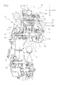
- Fig. 2 is a cross-sectional view taken along line II-II of Fig. 1 .
- the engine unit 5 includes an engine 10, which is one example of the internal combustion engine according to the present invention, and a V-belt type continuously variable transmission (hereinafter referred to as "CVT") 20.
- the CVT 20 is one example of a transmission.
- the engine 10 and the CVT 20 integrally form the engine unit 5, but it is of course possible that the engine 10 and a transmission may be separated from each other.
- the engine 10 is an engine that has a single cylinder, in other words, a single-cylinder engine.
- the engine 10 is a four-stroke engine, which repeats an intake stroke, a compression stroke, a combustion stroke, and an exhaust stroke, one after another.
- the engine 10 has a crankcase 11, a cylinder block 12 extending frontward from the crankcase 11, a cylinder head 13 connected to a front portion of the cylinder block 12, and a cylinder head cover 14 connected to a front portion of the cylinder head 13.
- a cylinder 15 is formed inside the cylinder block 12.
- the cylinder 15 may be formed by a cylinder liner inserted in the body of the cylinder block 12 (i.e., in the portion of the cylinder block 12 other than the cylinder 15) or may be integrated with the body of the cylinder block 12. In other words, the cylinder 15 may be formed either separably or inseparably from the body of the cylinder block 12. A piston, not shown in the drawings, is accommodated slidably in the cylinder block 15.
- the cylinder head 13 covers a front portion of the cylinder 15.
- a recessed portion, not shown in the drawings, and an intake port an exhaust port, also not shown in the drawings, that are connected to the recessed portion are formed in the cylinder head 13.
- An intake pipe 35 (see Fig. 3 ) is connected to the intake port, and an exhaust pipe 38 is connected to the exhaust port.
- the top face of the piston, the inner circumferential surface of the cylinder 15, and the recessed portion together form a combustion chamber, which is not shown in the drawings.
- the piston is coupled to a crankshaft 17 via a connecting rod 16.
- the crank shaft 17 extends leftward and rightward.
- the crank shaft 17 is accommodated in the crankcase 11.
- crankcase 11, the cylinder block 12, the cylinder head 13, and the cylinder head cover 14 are separate parts, and they are fitted to each other. However, they may not be separate parts but may be integrated with each other as appropriate.
- the crankcase 11 and the cylinder block 12 may be formed integrally with each other, or the cylinder block 12 and the cylinder head 13 may be formed integrally with each other.
- the cylinder head 13 and the cylinder head cover 14 may be formed integrally with each other.
- the CVT 20 has a first pulley 21, which is a driving pulley, a second pulley 22, which is a driven pulley, and a V-belt 23 wrapped around the first pulley 21 and the second pulley 22.
- a left end portion of the crankshaft 17 protrudes to the left from the crankcase 11.
- the first pulley 21 is fitted to the left end portion of the crankshaft 17.
- the second pulley 22 is fitted to a main shaft 24.
- the main shaft 24 is coupled to a rear wheel shaft 25 via a gear mechanism, which is not shown in the drawings.
- Fig. 2 depicts the state in which the transmission ratio for a front portion of the first pulley 21 and that for a rear portion of the first pulley 21 are different from each other.
- the second pulley 22 has the same configuration.
- a transmission case 26 is provided on the left of the crankcase 11.
- the CVT 20 is accommodated in the transmission case 26.
- An alternator 27 is provided on a right side portion of the crankshaft 17.
- a fan 28 is secured to a right end portion of the crankshaft 17.
- the fan 28 rotates with the crankshaft 17.
- the fan 28 is formed such as to suck air to the left by rotating.
- An air shroud 30 is disposed on the right of the crankcase 11, the cylinder block 12, and the cylinder head 13.
- the alternator 27 and the fan 28 are accommodated in the air shroud 30.
- the air shroud 30 and the fan 28 are one example of an air guide member, and they serve the role of guiding air mainly to the crank case 11, the cylinder block 12, and the cylinder head 13.
- a suction port 31 is formed in the air shroud 30.
- the suction port 31 is positioned on the right of the fan 28.
- the suction port 31 is formed at a position facing the fan 28. As indicated by arrow A in Fig. 2 , the air sucked by the fan 28 is introduced through the suction port 31 into the air shroud 30 and is supplied to, for example, the crank case 11, the cylinder block 12, and the cylinder head 13.
- Fig. 3 is a right side view illustrating a portion of the engine 10.
- the air shroud 30 is mounted to the crankcase 11, the cylinder block 12, and the cylinder head 13, and it extends frontward along the cylinder block 12 and the cylinder head 13.
- the air shroud 30 covers right side portions of the crank case 11, the cylinder block 12, and the cylinder head 13.
- the air shroud 30 partially covers upper and lower portions of the cylinder block 12 and the cylinder head 13.
- the engine 10 is a type of engine in which the cylinder block 12 and the cylinder head 13 extend in a horizontal direction or in a direction inclined slightly upward with respect to a horizontal direction toward the front, that is, what is called a horizontally mounted type engine.
- Reference character L1 represents the line that passes through the center of the cylinder 15 (see Fig. 2 , the line is hereinafter referred to as the "cylinder axis").
- the cylinder axis L1 extends in a horizontal direction or in a direction slightly inclined from a horizontal direction. It should be noted, however, that the direction of the cylinder axis L 1 is not particularly limited.
- the inclination angle of the cylinder axis L 1 with respect to the horizontal plane may be from 0° to 15°, or may be greater.
- the engine 10 is an air-cooled engine, the entire body of which is cooled by air. As illustrated in Fig. 2 , a plurality of cooling fins 33 are formed on the cylinder block 12 and the cylinder head 13. However, the engine 10 may be an engine that has the cooling fins 33 but a portion of which is cooled by coolant. In other words, the engine 10 may be an engine a portion of which is cooled by air but another portion of which is cooled by coolant.
- the fins 33 of the engine 10 according to the present embodiment are formed in the following shape.
- the fins 33 according to the present embodiment protrude from the surfaces of the cylinder block 12 and the cylinder head 13 and extend so as to be orthogonal to the cylinder axis L1. In other words, the fins 33 extend in a direction orthogonal to the surfaces of the cylinder block 12 and the cylinder head 13.
- the fins 33 are arrayed in a direction along the cylinder axis L1. Gaps are provided between adjacent fins 33. The gap between the fins 33 may be uniform or may not be uniform.
- the fins 33 that are formed on the cylinder block 12 are formed over the top face 12a, the right face 12b, and the bottom face 12c (see Fig. 3 ) of the cylinder block 12,
- the fins 33 that are formed on the cylinder head 13 are formed over the top face 13a, the right face 13b, the bottom face 13c (see Fig. 3 ), and the left face 13d of the cylinder head 13. It should be noted, however, that the position of the fins 33 is not particularly limited.
- the fins 33 may be formed either only on the cylinder block 12 or only on the cylinder head 13.
- the thicknesses of the plurality of fins 33 are equal to each other. However, the fins 33 may have different thicknesses one from another. Each one of the fins 33 may have a uniform thickness irrespective of the location therein or may have different thicknesses from one location therein to another. In other words, the thickness of each of the fins 33 may be locally different.
- each of the fins 33 may be formed in a flat plate shape so that the surface of the fin 33 is a flat surface.
- the fin 33 may be curved, and the surface of the fin 33 may be a curved surface.
- the shape of the fin 33 is not limited to a flat plate shape, and the fin 33 may have various other shapes such as needle shapes and hemispherical shapes.
- the fin 33 does not need to extend in a direction orthogonal to the cylinder axis L1 but may extend in a direction parallel to the cylinder axis L1.
- the fin 33 may extend in a direction inclined with respect to the cylinder axis L1.
- the plurality of the fins 33 may extend either in the same direction or in different directions from each other.
- a sensor mounting boss 40 is formed on the top face 12a of the cylinder block 12.
- the boss 40 is disposed above the cylinder block 12.
- the boss 40 is disposed above the engine body (that is, the portion of the engine 10 excluding the boss 40).
- the boss 40 is disposed at a position that overlaps with the engine body.
- an intake pipe 35 is connected to the top face of the cylinder head 13.
- the boss 40 is formed on a face of the cylinder block 12 that corresponds to the face of the cylinder head 13 to which the intake pipe 35 is connected. It is also possible to form the boss 40 on the cylinder head 13.
- the boss 40 may be formed on the top face of the cylinder head 13, or may be formed on the face of the cylinder head 13 to which the intake pipe 35 is connected.
- reference numeral 19 an intake port.
- the intake port extends obliquely downward and rearward, forming a curve.
- the right end of the boss 40 is positioned more to the right than the left end of the intake port 19
- the left end of the boss 40 is positioned more to the left than the right end of the intake port 19. That is, at least a portion of the boss 40 and at least a portion of the intake port 19 are disposed at an aligned position with respect to the left-right direction. In other words, at least a portion of the boss 40 and at least a portion of the intake port 19 are lined up, one in front and the other behind.
- both the center of the boss 40 and the center of the intake port 19 are positioned on the cylinder axis L1.
- at least a portion of the boss 40 and at least a portion of the intake port 19 are at an aligned position with respect to the left-right direction so that a knock sensor 41 to be mounted to the boss 40 can be protected by the intake port 19 from a flying stone or the like from the front.
- the knock sensor 41 can be protected by the intake pipe 35 mounted to the intake port 19.
- a chain case 99 is provided on a left side portion of the cylinder block 12.
- a cam chain is disposed inside the chain case 99.
- a mount portion 96 for mounting a cam chain tensioner 97 is provided on a portion of the chain case 99, that is, on a left side portion of the top face 12a of the cylinder block 12.
- the cam chain tensioner 97 is inserted into a hole of the mount portion 96 so as to come into contact with the cam chain.
- the rear end of the boss 40 is positioned more to the rear than the front end of the cam chain tensioner 97, and the front end of the boss 40 is positioned more to the front than the rear end of the cam chain tensioner 97.
- At least a portion of the boss 40 and at least a portion of the cam chain tensioner 97 are disposed at an aligned position with respect to the front-rear direction. In other words, at least a portion of the boss 40 and at least a portion of the cam chain tensioner 97 are lined up, one on the right and the other on the left. Thus, by the mount portion 96 and the cam chain tensioner 97, the knock sensor 41 mounted to the boss 40 can be protected.
- the boss 40 is integrally formed with the cylinder block 12.
- the boss 40 is formed in a tubular shape having a large wall thickness.
- the top face of the boss 40 is formed in a flat surface. It should be noted, however, that the shape of the boss 40 is not particularly limited as long as the later-described knock sensor 41 can be mounted thereto.
- the boss 40 is continuous with some of the fins 33. In other words, the boss 40 is connected to some of the fins 33. More specifically, no gap is formed between the boss 40 and those fins 33.
- the boss 40 and those fins 33 are integrally formed with each other.
- the boss 40 is connected to three of the fins 33. It should be noted, however, that the number of the fins 33 that are connected to the boss 40 is not limited to three.
- the boss 40 may be connected to either a plurality of the fins 33 or with only one of the fins 33.
- boss 40 is connected to some of the fins 33 in the present embodiment, the boss 40 may not be connected to the fins 33.
- the boss 40 may be provided at a portion of the cylinder block 12 or the cylinder head 13 where the fins 33 are not formed.
- the boss 40 is formed at a position overlapping the cylinder axis L1, as viewed in plan.
- the boss 40 is formed at such a position that an extension line L2 of the center of the boss 40 (see Fig. 3 ) intersects with the cylinder axis L1.
- the boss 40 may be formed at such a position that the extension line L2 of the center of the boss 40 does not intersect with the cylinder axis L1.
- the boss 40 may be formed at a position that overlaps with an inner portion of the cylinder 15 but does not overlap with the cylinder axis L1, when viewed from a direction along the center of the boss 40. It is also possible to form the boss 40 at a position that does not overlap with an inner portion of the cylinder 15, when viewed from a direction along the center of the boss 40.
- the front-rear position of the boss 40 is not particularly limited.
- the center C2 of the boss 40 is positioned closer to the bottom dead center BDC than the midpoint MC between the top dead center TDC and the bottom dead center BDC of the piston. It is also possible to dispose the boss 40 further closer to the bottom dead center BDC. Conversely, it is also possible to dispose the boss 40 so as to be positioned closer to the top dead center TDC than the midpoint MC between the top dead center TDC and the bottom dead center BDC of the piston.
- the height of the boss 40 may be the same as the height of the fins 33. Alternatively, the height of the boss 40 may be higher than the height of the fins 33. In other words, a portion of the boss 40 may protrude from the fins 33. Alternatively, the height of the boss 40 may be lower than the height of the fins 33.
- the boss 40 extends in a direction orthogonal to the top face 12a of the cylinder block 12. Since the fins 33 protrude in a direction orthogonal to the top face 12a of the cylinder block 12, the protruding direction of the boss 40 and the protruding direction of the fins 33 are parallel to each other. However, the protruding direction of the boss 40 is not particularly limited, and the boss 40 may protrude in a direction inclined with respect to the top face 12a of the cylinder block 12.
- a heat insulation member 45 is placed on the boss 40, and the knock sensor 41 for detecting knocking is mounted on the heat insulation member 45.
- the heat insulation member 45 refers to a member having a lower thermal conductivity than the boss 40.
- the heat insulation member 45 and the knock sensor 41 are mounted to the boss 40 by a bolt 42.
- the knock sensor 41 it may be preferable to use, for example, a sensor that detects vibration and converts the vibration into an electric signal to output the signal (for example, a sensor equipped with a piezoelectric element).
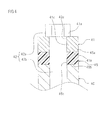
- Fig. 4 is a schematic cross-sectional view illustrating the boss 40, the heat insulation member 45, the knock sensor 41, and the bolt 42.
- the heat insulation member 45 is formed in a cylindrical shape.
- the heat insulation member 45 is formed in a cylindrical shape having substantially the same inner diameter and substantially the same outer diameter as those of the boss 40.
- the inner diameter of the heat insulation member 45 may be different from the inner diameter of the boss 40, and the outer diameter of the heat insulation member 45 may be different from the outer diameter of the boss 40.
- the heat insulation member 45 may not necessarily be formed in a cylindrical shape.
- the heat insulation member 45 may be formed in a C-shaped cross section.
- the heat insulation member 45 has an obverse face 45a and a reverse face 45b.
- Both the obverse face 45a and the reverse face 45b are formed to be flat surfaces.
- a through-hole 45c passing from the obverse face 45a through to the reverse face 45b is formed at the center of the heat insulation member 45.
- the heat insulation member 45 is formed of a single member. It is also possible, however, that the heat insulation member 45 be formed of a plurality of members. For example, the heat insulation member 45 may be formed by laminating a plurality of annular members.
- the knock sensor 41 is also formed in a cylindrical shape.
- the knock sensor 41 is formed in a cylindrical shape having substantially the same inner diameter and substantially the same outer diameter as those of the boss 40.
- the shape of the knock sensor 41 is not limited to the cylindrical shape and may be other shapes.
- the inner diameter of the knock sensor 41 may be different from the inner diameter of the boss 40, and the outer diameter of the knock sensor 41 may be different from the outer diameter of the boss 40.
- the knock sensor 41 has an obverse face 41a and a reverse face 41b. Both the obverse face 41a and the reverse face 41b are formed to be flat surfaces.
- a through-hole 41c passing from the obverse face 41a through to the reverse face 41b is formed at the center of the knock sensor 41.
- the inner diameter of the through-hole 41c of the knock sensor 41, the inner diameter of the through-hole 45c of the heat insulation member 45, and the inner diameter of the boss 40 are equal to each other.
- the bolt 42 is a fastener for mounting the heat insulation member 45 and the knock sensor 41 to the boss 40.
- the bolt 42 has a head 42a and a shaft portion 42b extending downward from the head 42a.
- the head 42a and the shaft portion 42b are integrally formed with each other.
- the head 42a is formed to have a larger diameter than the shaft portion 42b.
- the head 42a is formed to have a hexagonal cross section so that it can engage with a tool such as a hex wench.
- the shape of the head 42a is not particularly limited. For example, a straight slot or a cross slot engaging with a screwdriver may be formed in the head 42a. Alternatively, another type of engaging portion for engaging with a tool for rotating the head 42a may be formed in the head 42a.
- a helical groove is formed in the outer circumferential surface of the shaft portion 42b.
- a helical groove is also formed in the inner circumferential surface of the boss 40.
- the observe face 41 a of the knock sensor 41 is in contact with the head 42a of the bolt 42.
- the reverse face 41b of the knock sensor 41 is in contact with the obverse face 45a of the heat insulation member 45.
- the observe face 41a of the knock sensor 41 and the head 42a of the bolt 42 are brought into intimate contact with each other, and the reverse face 41b of the knock sensor 41 and the obverse face 45a of the heat insulation member 45 are brought into intimate contact with each other.
- Bringing the reverse face 41b of the knock sensor 41 and the obverse face 45a of the heat insulation member 45 into intimate contact with each other enables vibrations to be transmitted from the boss 40 via the heat insulation member 45 to the knock sensor 41 in good condition.
- bringing the obverse face 41a of the knock sensor 41 and the head 42a of the bolt 42 into intimate contact with each other enables vibrations to be transmitted in good condition from the boss 40 to the knock sensor 41 through the bolt 42.
- a helical groove that engages with the helical groove of the bolt 42 in one or both of the inner circumferential surface of the through-hole 45c of the heat insulation member 45 and the inner circumferential surface of the through-hole 41c of the knock sensor 41.
- a helical groove is formed in the inner circumferential surface of the through-hole 41c of the knock sensor 41, the contact area between the bolt 42 and the knock sensor 41 is increased, so that vibration can be transmitted from the bolt 42 to the knock sensor 41 in better condition.
- the method of securing the bolt 42 is not necessarily limited to the just-described method.
- Another possible method is as follows. A bolt 42 is embedded in the boss 40 in advance, then the heat insulation member 45, the knock sensor 41, and a nut are fitted to the bolt 42 in that order, and then, the nut is tightened.
- the heat insulation member 45 is for reducing the heat quantity that is transmitted from the boss 40 to the knock sensor 41.
- the heat insulation member 45 is formed of a material having a lower thermal conductivity than the material of the cylinder block 12 (i.e., the material of the boss 40).
- the knock sensor 41 is a sensor that detects vibration
- the heat insulation member 45 be formed of a material that does not easily damp vibration.
- the heat insulation member 45 be formed of a material that suppresses heat conduction but does not easily damp vibration. Generally, a material with a high density can transmit vibration in good condition.
- the material of the heat insulation member 45 is not particularly limited, but, for example, it is possible to suitably use a material that has a thermal conductivity 1/10 or less (preferably 1/100 or less) and a density of 1/10 or greater of that of the material of the cylinder block 12.
- the heat insulation member 45 and the boss 40 may be formed of the same kind of material or may be formed of different kinds of materials.
- the boss 40 may be made of a metal (such as cast iron and aluminum) while the heat insulation member 45 may be made of a resin. It is also possible that the boss 40 may be made of a metal while the heat insulation member 45 may be made of a ceramic.
- the material of the cylinder block 12 is not particularly limited. Usable examples include ADC12 (DC material) having a thermal conductivity, as determined according to JIS R1611, of about 96 W/(m ⁇ K) and a density of 2.68 kg/m 3 , AC4B (LP) having a thermal conductivity of about 134 W/(m ⁇ K) and a density of about 2.77 kg/m 3 , FC250 (cast iron) having a thermal conductivity of about 50 W/(m ⁇ K) and a density of 7.3 kg/m 3 , and alumina ceramic having a thermal conductivity of about 29 W/(m ⁇ K) and a density of about 3.9 kg/m 3 .
- a suitable example of the heat insulation member 45 is a phenolic resin.
- the thermal conductivity of the phenolic resin determined according to JIS A1412 is about 0.2 W/(m ⁇ K), which is less than 1/100 of the thermal conductivities of the above-mentioned materials.
- the density of the phenolic resin is about 1.25 kg/m 3 , which is greater than 1/10 of the densities of the above-mentioned materials.
- the intake pipe 35 is connected to the top face 13a of the cylinder head 13.
- a throttle body 36 that accommodates a throttle valve, which is not shown in the drawings, is connected to the intake pipe 35.
- the knock sensor 41 When viewed from side, the knock sensor 41 is disposed below the intake pipe 35 or the throttle body 36.
- a fuel injection valve 37 is disposed in front of the intake pipe 35. When viewed from side, the knock sensor 41 is disposed on the opposite side of the intake pipe 35 (the left side of Fig. 3 ) to the side on which the fuel injection valve 37 is disposed (the right side of Fig. 3 ).
- the exhaust pipe 38 is connected to the bottom face 13c of the cylinder head 13.
- the heat generated by combustion in the combustion chamber is conducted mainly from the cylinder block 12 via the boss 40 to the knock sensor 41. That is, the knock sensor 41 is heated mainly by heat conduction from the boss 40.
- the heat insulation member 45 is provided between the boss 40 and the knock sensor 41. This serves to prevent the knock sensor 41 from being heated by the boss 40. As a result, the temperature rise of the knock sensor 41 can be inhibited because the knock sensor 41 is not easily heated by the boss 40, so the reliability of the knock sensor 41 can be enhanced.
- the vibration transmitted from the boss 40 to the knock sensor 41 may be damped, and the detection accuracy of the knock sensor 41 may be lowered.
- a portion of the bolt 42 for mounting the knock sensor 41 is in contact with the boss 40, and another portion thereof is in contact with the knock sensor 41. More specifically, the head 42a of the bolt 42 is in contact with the obverse face 41a of the knock sensor 41, and a portion of the outer circumferential surface of the shaft portion 42b of the bolt 42 is in contact with the inner circumferential surface of the boss 40. This means that the vibration of the boss 40 is transmitted to the knock sensor 41 not just through the heat insulation member 45 but also through the bolt 42.
- the bolt 42 serves the role of transmitting the vibration of the boss 40 to the knock sensor 41, in addition to the role of fitting the knock sensor 41 and the heat insulation member 45 to the boss 40. Therefore, even though the heat insulation member 45 is interposed between the boss 40 and the knock sensor 41, the detection accuracy of the knock sensor 41 can be kept high.
- the combustion chamber is formed inside the cylinder block 12 and the cylinder head 13.
- vibration resulting from the knocking propagates from the combustion chamber to the cylinder block 12, the cylinder head 13, and so forth.
- the knock sensor 41 is mounted to the cylinder block 12.
- the knock sensor 41 is disposed in the vicinity of the combustion chamber, in other words, in the vicinity of the location at which knocking occurs. As a result, it is possible to detect knocking with high accuracy by the knock sensor 41.
- the vicinity of the combustion chamber is a location suitable for detection of knocking, it is a location in which the temperature is high.
- the temperature of the cylinder block 12 tends to be higher than that of the crankcase 11. Consequently, merely mounting the knock sensor 41 on the boss 40 of the cylinder block 12 may pose a risk of heating the knock sensor 41 by the cylinder block 12 with a high temperature, causing the temperature of the knock sensor 41 to become too high.
- the heat insulation member 45 is provided between the boss 40 and the knock sensor 41 as described above. Therefore, although the knock sensor 41 is mounted to the cylinder block 12, the temperature rise of the knock sensor 41 can be suppressed.
- the cylinder head 13 has the top face 13a, the right face 13b, the bottom face 13c, and the left face 13d.
- the intake pipe 35 is connected to the top face 13a, while the exhaust pipe 38 is connected to the bottom face 13c.
- the cylinder block 12 likewise has the top face 12a, the right face 12b, the bottom face 12c, and the left face 12d.
- the boss 40 is formed on the top face 12a. More specifically, the boss 40 is formed on, of the faces 12a to 12d of the cylinder block 12, the face 12a that corresponds to the face 13a of the cylinder head 13 to which the intake pipe 35 is connected. Air at ambient temperature flows through the intake pipe 35, while high-temperature exhaust gas after combustion flows through the exhaust pipe 38.
- the intake pipe 35 is colder than the exhaust pipe 38, and the top face 12a and the top face 13a are colder than the bottom face 12c and the bottom face 13c.
- the boss 40 is provided on the top face 12a, which is colder. Therefore, the temperature rise of the knock sensor 41 can be even more suppressed.
- the fins 33 are formed on the cylinder block 12 and the cylinder head 13. As a result, the coolability of the cylinder block 12 and the cylinder head 13 can be enhanced.
- the boss 40 is connected to some of the fins 33. As a result, the heat of the boss 40 does not remain in the boss 40 itself, but it is released vigorously through the fins 33. The coolability of the boss 40 is enhanced, and the temperature of the boss 40 is prevented from becoming excessively high. Therefore, it becomes possible to suppress the temperature rise of the knock sensor 41 further.
- the air guided by the air shroud 30 is supplied to the knock sensor 41, in addition to the boss 40. Accordingly, the knock sensor 41 itself can also be cooled effectively by the air.
- the air shroud 30 covers at least a portion of the cylinder block 12 and the cylinder head 13. The air shroud 30 supplies air not only to the boss 40 but also to the cylinder block 12, the cylinder head 13, and so forth. As a result, the cylinder block 12, the cylinder head 13, and so forth can be cooled effectively. This also serves to prevent the temperature rise of the boss 40 and suppress the temperature rise of the knock sensor 41.
- the intake pipe 35 and the throttle body 36 are disposed above the boss 40.
- the air shroud 30 is not provided, there may be cases in which the air flow stagnates in the region around the boss 40 that is above the top face 12a of the cylinder block 12, due to the influence of the intake pipe 35 and the throttle body 36.
- a good flow of air can be supplied to the boss 40, which is positioned below the intake pipe 35 or the throttle body 36, because the air shroud 30 is provided.
- the boss 40 can be cooled effectively, and the temperature rise of the knock sensor 41 can be suppressed.
- the cylinder block 12 and the cylinder head 13 extend frontward and obliquely upward from the crankcase 11.
- the cylinder axis L1 is inclined from a horizontal plane. For that reason, without any design change, air does not flow smoothly over the top face 12a of the cylinder block 12 in comparison with the right face 12b, the bottom face 12c, and the left face 12d.
- air can be supplied to the boss 40 by the air shroud 30. As a result, although the boss 40 is provided on the top face 12a, to which air is inherently not supplied smoothly, the boss 40 can be cooled sufficiently, and the temperature rise of the knock sensor 41 can be suppressed.
- the boss 40 is formed on the cylinder block 12.
- the boss 40 is disposed at a location even closer to the location at which knocking occurs, so the detection accuracy of the knock sensor 41 can be even more increased.
- the cylinder head 13 tends to become hotter than the cylinder block 12.
- the temperature rise of the knock sensor 41 can be suppressed by interposing the heat insulation member 45 between the boss 40 and the knock sensor 41.
- the knock sensor 41 may result in a fault.
- the boss 40 is provided on the top face 12a of the cylinder block 12. The top face 12a of the cylinder block 12 is less likely to be hit by the stone chips and the like that are kicked up from the ground than the right face 12b, the bottom face 12c, and the left face 12d. Therefore, the knock sensor 41 can be inhibited from being hit by the stone chips and the like.
- the intake pipe 35 or the throttle body 36 is disposed above the knock sensor 41, as illustrated in Fig. 3 .
- the intake pipe 35 and the throttle body 36 are components that have greater strength than the knock sensor 41. Even if an object falls from above, the knock sensor 41 can be protected by the intake pipe 35 or the throttle body 36.
- the boss 40 is disposed at such a position that the extension line L2 of the center of the boss 40 passes through the cylinder 15, particularly at such a position that the extension line L2 intersects the cylinder axis L1.
- the knock sensor 41 is disposed at such a position that knocking can be detected more easily. Therefore, the present embodiment can increase the detection accuracy of the knock sensor 41.
- the boss 40 is formed so as to be connected to some of the fins 30. However, it is not absolutely necessary that the boss 40 is connected to some of the fins 30. As illustrated in Fig. 5 , in the engine 10 according to the second embodiment, the boss 40 is independent from the fins 30.
- no fin 33 is formed at a base portion (in other words, a rear portion) 12r of the cylinder block 12.
- the boss 40 is provided at the base portion 12r of the top face of the cylinder block 12, that is, at the portion in which no fin 33 is formed.
- the boss 40 may be provided on any other faces of the cylinder block 12 than the top face thereof.
- the heat insulation member 45 is provided on the boss 40, and the knock sensor 41 is provided further on the heat insulation member 45.
- the heat insulation member 45 is disposed between the boss 40 and the knock sensor 41.
- the heat insulation member 45 and the knock sensor 41 are mounted to the boss 40 by a bolt 42.
- the structure and arrangement of the boss 40, the heat insulation member 45, the knock sensor 41, and the bolt 42 are the same as those in the first embodiment (see Fig. 4 ).
- the air outside the air shroud 30 is sucked through the suction port 31 into the air shroud 30.
- the sucked air A is guided generally frontward, and is supplied to the boss 40 and the knock sensor 41.
- the boss 40 and the knock sensor 41 are cooled by this air.
- the air that has cooled the boss 40 and the knock sensor 41 flows along the cylinder block 12 and the cylinder head 13 from the front to the left, to cool the cylinder block 12 and the cylinder head 13.
- fins 33 are formed in front of the boss 40.
- the air shroud 30 is configured so as to guide air successively to the boss 40 and then to the fins 33 in that order.
- the air with a relatively low temperature that is sucked from the suction port 31 flows through the surrounding region of the boss 40 and the knock sensor 41. At that time, the air itself is heated because it cools the boss 40 and the knock sensor 41, and the temperature thereof rises.
- the air the temperature of which has been raised is supplied to the fins 33.
- the fins 33 are cooled by the air the temperature of which has been raised.
- the temperature rise of the knock sensor 41 can be suppressed because the heat insulation member 45 is provided between the boss 40 and the knock sensor 41. Moreover, since vibration is transmitted from the boss 40 to the knock sensor 41 through the bolt 42, the detection accuracy of the knock sensor 41 can be kept high, although the heat insulation member 45 is interposed between the boss 40 and the knock sensor 41. In addition thereto, substantially the same advantageous effects as obtained by the first embodiment can be obtained.
- the air shroud 30 is configured so as to guide air successively to the boss 40 and then to the fins 33 in that order. For this reason, the boss 40 and the knock sensor 41 are supplied with the air with a relatively low temperature before cooling the fins 33. Thus, the temperature rise of the knock sensor 41 can be suppressed more effectively.
- the boss 40 is formed on the cylinder block 12.
- the boss 40 may be formed on a portion other than the cylinder block 12.
- the boss 40 is formed on the crank case 11.
- the position of the boss 40 is not particularly limited, but in the present embodiment, the boss 40 is formed on a front portion of the crankcase 11. In other words, the boss 40 is formed in a portion of the crank case 11 near the cylinder block 12.
- the boss 40 is provided on the top face 11a of the crankcase 11, and it is formed so as to extend frontward and obliquely upward.
- the air shroud 30 is fitted to the crank case 11, the cylinder block 12 and the cylinder head 13.
- the air that is sucked by the fan 28 from the suction port 31 generally flows over the crank case 11, then the cylinder block 12, and then the cylinder head 13 in that order.
- the air before cooling the cylinder block 12 and the cylinder head 13 is supplied to the boss 40 and the knock sensor 41.
- the air that has cooled the boss 40 and the knock sensor 41 is thereafter supplied to the cylinder block 12 and the cylinder head 13, to cool the cylinder block 12 and the cylinder head 13.
- the crank case 11 has a lower temperature than the cylinder block 12 and the cylinder head 13. Therefore, according to the present embodiment, the temperature rise of the boss 40 can be suppressed even more, and the temperature rise of the knock sensor 41 can be suppressed even further.
- the air with a relatively low temperature that has not yet been heated by the cylinder block 12 or the cylinder head 13 is supplied to the boss 40 and the knock sensor 41.
- the boss 40 and the knock sensor 41 can be cooled effectively.
- the boss 40 is formed on the top face 12a of the cylinder block 12.
- the boss 40 is formed on the top face 11a of the crank case 11.
- the boss 40 may be formed on, for example, other faces of the cylinder block 12 than the top face 12a thereof.
- the boss 40 is formed on the right face 12b of the cylinder block 12.
- no fin 33 is formed at a base portion of the cylinder block 12, and the boss 40 is formed on the right face 12b of the base portion thereof.
- the boss 40 is independent from the fins 33.
- the boss 40 may be connected to some of the fins 40 as in the first embodiment. The rest of the configurations are similar to the first embodiment, and therefore a further description thereof will be omitted.
- the temperature rise of the knock sensor 41 can be suppressed because the heat insulation member 45 is provided between the boss 40 and the knock sensor 41. Moreover, since vibration is transmitted from the boss 40 to the knock sensor 41 through the bolt 42, the detection accuracy of the knock sensor 41 can be kept high, although the heat insulation member 45 is interposed between the boss 40 and the knock sensor 41. In addition thereto, substantially the same advantageous effects as obtained by the first embodiment can be obtained.
- the suction port 31 is formed in a right side portion of the air shroud 30, and the air is introduced from the right to the left.
- the boss 40 is formed on the right face 12b of the cylinder block 12 and the knock sensor 41 is disposed on the right of the cylinder block 12. Accordingly, the air introduced from the suction port 31 can be supplied immediately to the boss 40 and the knock sensor 41. As a result, the boss 40 and the knock sensor 41 can be cooled effectively.
- the boss 40 and the knock sensor 41 are supplied with the air with a relatively low temperature before cooling the fins 33.
- the boss 40 and the knock sensor 41 can be cooled effectively, and the temperature rise of the knock sensor 41 can be suppressed sufficiently.
- the engine 10 in the foregoing embodiments is a horizontally mounted type engine in which the cylinder axis L1 extends in a horizontal direction or in a substantially horizontal direction.
- the direction of the cylinder axis L1 is not limited to the horizontal direction or the substantially horizontal direction.
- an engine 50 according to the fifth embodiment is what is called a vertically mounted type engine, in which the cylinder axis L1 extends in a substantially vertical direction.
- the inclination angle of the cylinder axis L 1 from a horizontal plane is 45 degrees or greater.
- the straddle-type vehicle is what is called an on-road -type motorcycle 1A.
- the motorcycle 1A is equipped with a front wheel 3, a rear wheel 4, and a vehicle body 2 having a handlebar 6, a seat 7, and so forth.
- the rear wheel 4 is coupled to an engine 50 via a transmission chain (not shown) and is driven by the engine 50.
- the engine 50 is fixed to the engine unit 9 but is non-swingably fixed to a body frame 9.
- the engine 50 has a crankcase 11, a cylinder block 12 extending frontward and obliquely upward from the crankcase 11, a cylinder head 13 connected to an upper portion of the cylinder block 12, and a cylinder head cover 14 connected to an upper portion of the cylinder head 13.
- fins 33 are formed on the cylinder block 12 and the cylinder head 13.
- a boss (not shown) is formed on the rear face of the cylinder block 12.
- a heat insulation member (not shown) is provided on the boss.
- a knock sensor 41 is provided on the heat insulation member.
- the heat insulation member and the knock sensor 41 are mounted to the boss by a bolt 42.
- the structure and arrangement of the boss, the heat insulation member, the knock sensor 41, and the bolt 42 are the same as those in the first embodiment (see Fig. 4 ), and therefore a further description thereof will be omitted.
- the temperature rise of the knock sensor 41 can be suppressed because the heat insulation member is provided between the boss and the knock sensor 41. Moreover, since vibration is transmitted from the boss to the knock sensor 41 through the bolt 42, the detection accuracy of the knock sensor 41 can be kept high, although the heat insulation member is interposed between the boss and the knock sensor 41. In addition thereto, substantially the same advantageous effects as obtained by the first embodiment can be obtained.
- the head 42a of the bolt 42 and the observe face 41a of the knock sensor 41 are in direct contact with each other (see Fig. 4 ).
- another member such as a washer
- the boss 40 is formed at such a position that the extension line L2 of the center of the boss 40 intersects the cylinder axis L1.
- the position of the boss 40 is not particularly limited.
- the engines 10 and 50 are air-cooled engines.
- the internal combustion engine according to the present invention may be an engine in which a portion thereof is cooled by coolant.
- a water jacket may be formed in the cylinder head, and the cylinder head may be cooled by coolant.
- the fin or fins may be formed only on the cylinder block.
- the engines 10 and 50 are four-stroke engines.
- the internal combustion engine according to the present invention may be a two-stroke engine.
Landscapes
- Engineering & Computer Science (AREA)
- Chemical & Material Sciences (AREA)
- Combustion & Propulsion (AREA)
- Mechanical Engineering (AREA)
- General Engineering & Computer Science (AREA)
- Physics & Mathematics (AREA)
- General Physics & Mathematics (AREA)
- Acoustics & Sound (AREA)
- Cylinder Crankcases Of Internal Combustion Engines (AREA)
Abstract
Description
- The present invention relates to an internal combustion engine fitted with a sensor for detecting knocking. The invention also relates to a straddle-type vehicle equipped with the engine.
- An internal combustion engine can cause knocking in some cases, depending on its operating conditions. Knocking should be avoided as much as possible because it results in, for example, unusual noise and performance degradation of the internal combustion engine. Conventionally, it is known that a sensor for detecting knocking, that is, a knock sensor, is fitted to an internal combustion engine. It is also known that, upon detecting knocking by the knock sensor, an action such as changing ignition timing is taken.
-
JP 2004-301106 A - A water-cooled engine needs a flow passage for coolant, i.e., a water jacket, to be formed in, for example, a cylinder block and a cylinder head. It also requires, for example, a pump for conveying the coolant and a radiator for cooling the coolant. For this reason, the structure of the water-cooled engine tends to be complicated.
- A straddle-type vehicle equipped with a single-cylinder internal combustion engine (hereinafter referred to as a "single-cylinder engine") is known, such as represented by a relatively small-sized motorcycle. The single-cylinder engine has the advantage that it has a simpler structure than the multi-cylinder engine. To fully exploit the advantage, the single-cylinder engine is desired to have a relatively simple cooling structure. For that reason, conventionally, at least a portion of the cylinder block and the cylinder head is cooled by air.
- In the air-cooled engine provided with fins, the cylinder block and so forth are cooled from the surface. On the contrary, in the water-cooled engine, the cylinder block and so forth are cooled from a water jacket disposed inside the surface. The knock sensor is disposed on a boss provided on the surface of the engine. This means that, when the boss is provided for the air-cooled engine provided with fins, engine cooling becomes insufficient, and consequently, cooling of the knock sensor may become insufficient. In other words, when the above-described conventional technique, in which it is assumed that cooling is done from the inside of the surface of the engine, is applied to the air-cooled engine, the temperature of the knock sensor may become too high, degrading the reliability of the knock sensor.
- It is an object of the present invention to suppress the temperature rise of the knock sensor and to improve the reliability of the knock sensor in a single-cylinder internal combustion engine fitted with a knock sensor.
- The present invention provides an internal combustion engine comprising: a single-cylinder internal combustion engine for a vehicle, comprising: a crank case accommodating a crankshaft; a cylinder block connected to the crank case and having a cylinder formed therein; a cylinder head connected to the cylinder block; a sensor mounting boss formed on the crank case, the cylinder block, or the cylinder head; a sensor for detecting knocking, mounted to the boss, a fin formed on at least a portion of the cylinder block and the cylinder head; and a heat insulation member interposed between the boss and the sensor, heat insulation member being made of a material having a lower thermal conductivity than the boss.
- The present invention makes it possible to suppress the temperature rise of the knock sensor and to improve the reliability of the knock sensor in a single-cylinder internal combustion engine fitted with a knock sensor.
-
-
Fig. 1 is a left side view of a motorcycle according to a first embodiment; -
Fig. 2 is a cross-sectional view taken along line II-II ofFig. 1 ; -
Fig. 3 is a right side view illustrating a portion of an engine according to the first embodiment; -
Fig. 4 is a cross-sectional view illustrating a boss, a heat insulation member, and a knock sensor through which a bolt is inserted; -
Fig. 5 is a right side view illustrating a portion of an engine according to a second embodiment; -
Fig. 6 is a right side view illustrating a portion of an engine according to a third embodiment; -
Fig. 7 is a cross-sectional view corresponding toFig. 2 , illustrating an engine unit according to a fourth embodiment; and -
Fig. 8 is a left side view of a motorcycle according to a fifth embodiment. - As illustrated in
Fig. 1 , the straddle-type vehicle according to first embodiment is ascooter type motorcycle 1. Although themotorcycle 1 is one example of the straddle-type vehicle according to the present invention, the straddle-type vehicle according to the present invention is not limited to thescooter type motorcycle 1. The straddle-type vehicle according to the present invention may be any other type of motorcycle, such as a moped type motorcycle, an off-road type motorcycle, or an on-road type motorcycle. In addition, the straddle-type vehicle according to the present invention is intended to mean any type of vehicle on which a rider straddles to ride, and it is not limited to a two-wheeled vehicle. The straddle-type vehicle according to the present invention may be, for example, a three-wheeled vehicle that changes its traveling direction by leaning the vehicle body. The straddle-type vehicle according to the present invention may be other type of straddle-type vehicle such as an ATV (All Terrain Vehicle). - In the following description, the terms "front," "rear," "left," and "right" respectively refer to front, rear, left, and right as defined based on the perspective of the rider of the
motorcycle 1. Reference characters F, Re, L, and R in the drawings indicate front, rear, left, and right, respectively. - The
motorcycle 1 has avehicle body 2, afront wheel 3, arear wheel 4, and anengine unit 5 for driving therear wheel 4. Thevehicle body 2 has ahandlebar 6, which is operated by the rider, and aseat 7, on which the rider is to be seated. Theengine unit 5 is what is called a unit swing type engine unit, and it is supported by a body frame, not shown in the drawings, so that it can pivot about a pivot shaft 8. The engine unit is supported so as to be swingable relative to the body frame. -
Fig. 2 is a cross-sectional view taken along line II-II ofFig. 1 . As illustrated inFig. 2 , theengine unit 5 includes anengine 10, which is one example of the internal combustion engine according to the present invention, and a V-belt type continuously variable transmission (hereinafter referred to as "CVT") 20. The CVT 20 is one example of a transmission. In the present embodiment, theengine 10 and the CVT 20 integrally form theengine unit 5, but it is of course possible that theengine 10 and a transmission may be separated from each other. - The
engine 10 is an engine that has a single cylinder, in other words, a single-cylinder engine. Theengine 10 is a four-stroke engine, which repeats an intake stroke, a compression stroke, a combustion stroke, and an exhaust stroke, one after another. Theengine 10 has acrankcase 11, acylinder block 12 extending frontward from thecrankcase 11, acylinder head 13 connected to a front portion of thecylinder block 12, and acylinder head cover 14 connected to a front portion of thecylinder head 13. Acylinder 15 is formed inside thecylinder block 12. - The
cylinder 15 may be formed by a cylinder liner inserted in the body of the cylinder block 12 (i.e., in the portion of thecylinder block 12 other than the cylinder 15) or may be integrated with the body of thecylinder block 12. In other words, thecylinder 15 may be formed either separably or inseparably from the body of thecylinder block 12. A piston, not shown in the drawings, is accommodated slidably in thecylinder block 15. - The
cylinder head 13 covers a front portion of thecylinder 15. A recessed portion, not shown in the drawings, and an intake port an exhaust port, also not shown in the drawings, that are connected to the recessed portion are formed in thecylinder head 13. An intake pipe 35 (seeFig. 3 ) is connected to the intake port, and anexhaust pipe 38 is connected to the exhaust port. The top face of the piston, the inner circumferential surface of thecylinder 15, and the recessed portion together form a combustion chamber, which is not shown in the drawings. The piston is coupled to acrankshaft 17 via a connectingrod 16. Thecrank shaft 17 extends leftward and rightward. Thecrank shaft 17 is accommodated in thecrankcase 11. - In the present embodiment, the
crankcase 11, thecylinder block 12, thecylinder head 13, and thecylinder head cover 14 are separate parts, and they are fitted to each other. However, they may not be separate parts but may be integrated with each other as appropriate. For example, thecrankcase 11 and thecylinder block 12 may be formed integrally with each other, or thecylinder block 12 and thecylinder head 13 may be formed integrally with each other. Alternatively, thecylinder head 13 and thecylinder head cover 14 may be formed integrally with each other. - The
CVT 20 has afirst pulley 21, which is a driving pulley, asecond pulley 22, which is a driven pulley, and a V-belt 23 wrapped around thefirst pulley 21 and thesecond pulley 22. A left end portion of thecrankshaft 17 protrudes to the left from thecrankcase 11. Thefirst pulley 21 is fitted to the left end portion of thecrankshaft 17. Thesecond pulley 22 is fitted to amain shaft 24. Themain shaft 24 is coupled to arear wheel shaft 25 via a gear mechanism, which is not shown in the drawings.Fig. 2 depicts the state in which the transmission ratio for a front portion of thefirst pulley 21 and that for a rear portion of thefirst pulley 21 are different from each other. Thesecond pulley 22 has the same configuration. Atransmission case 26 is provided on the left of thecrankcase 11. TheCVT 20 is accommodated in thetransmission case 26. - An
alternator 27 is provided on a right side portion of thecrankshaft 17. Afan 28 is secured to a right end portion of thecrankshaft 17. Thefan 28 rotates with thecrankshaft 17. Thefan 28 is formed such as to suck air to the left by rotating. Anair shroud 30 is disposed on the right of thecrankcase 11, thecylinder block 12, and thecylinder head 13. Thealternator 27 and thefan 28 are accommodated in theair shroud 30. Theair shroud 30 and thefan 28 are one example of an air guide member, and they serve the role of guiding air mainly to the crankcase 11, thecylinder block 12, and thecylinder head 13. Asuction port 31 is formed in theair shroud 30. Thesuction port 31 is positioned on the right of thefan 28. Thesuction port 31 is formed at a position facing thefan 28. As indicated by arrow A inFig. 2 , the air sucked by thefan 28 is introduced through thesuction port 31 into theair shroud 30 and is supplied to, for example, thecrank case 11, thecylinder block 12, and thecylinder head 13. -
Fig. 3 is a right side view illustrating a portion of theengine 10. As illustrated inFig. 3 , theair shroud 30 is mounted to thecrankcase 11, thecylinder block 12, and thecylinder head 13, and it extends frontward along thecylinder block 12 and thecylinder head 13. Theair shroud 30 covers right side portions of thecrank case 11, thecylinder block 12, and thecylinder head 13. In addition, theair shroud 30 partially covers upper and lower portions of thecylinder block 12 and thecylinder head 13. - As illustrated in
Fig. 3 , theengine 10 according to the present embodiment is a type of engine in which thecylinder block 12 and thecylinder head 13 extend in a horizontal direction or in a direction inclined slightly upward with respect to a horizontal direction toward the front, that is, what is called a horizontally mounted type engine. Reference character L1 represents the line that passes through the center of the cylinder 15 (seeFig. 2 , the line is hereinafter referred to as the "cylinder axis"). The cylinder axis L1 extends in a horizontal direction or in a direction slightly inclined from a horizontal direction. It should be noted, however, that the direction of thecylinder axis L 1 is not particularly limited. For example, the inclination angle of thecylinder axis L 1 with respect to the horizontal plane may be from 0° to 15°, or may be greater. - The
engine 10 according to the present embodiment is an air-cooled engine, the entire body of which is cooled by air. As illustrated inFig. 2 , a plurality of coolingfins 33 are formed on thecylinder block 12 and thecylinder head 13. However, theengine 10 may be an engine that has the coolingfins 33 but a portion of which is cooled by coolant. In other words, theengine 10 may be an engine a portion of which is cooled by air but another portion of which is cooled by coolant. - Although the specific shape of the
fins 33 is not particularly limited, thefins 33 of theengine 10 according to the present embodiment are formed in the following shape. Thefins 33 according to the present embodiment protrude from the surfaces of thecylinder block 12 and thecylinder head 13 and extend so as to be orthogonal to the cylinder axis L1. In other words, thefins 33 extend in a direction orthogonal to the surfaces of thecylinder block 12 and thecylinder head 13. Thefins 33 are arrayed in a direction along the cylinder axis L1. Gaps are provided betweenadjacent fins 33. The gap between thefins 33 may be uniform or may not be uniform. - In the present embodiment, the
fins 33 that are formed on thecylinder block 12 are formed over thetop face 12a, theright face 12b, and thebottom face 12c (seeFig. 3 ) of thecylinder block 12, Thefins 33 that are formed on thecylinder head 13 are formed over thetop face 13a, theright face 13b, thebottom face 13c (seeFig. 3 ), and theleft face 13d of thecylinder head 13. It should be noted, however, that the position of thefins 33 is not particularly limited. Thefins 33 may be formed either only on thecylinder block 12 or only on thecylinder head 13. - The thicknesses of the plurality of
fins 33 are equal to each other. However, thefins 33 may have different thicknesses one from another. Each one of thefins 33 may have a uniform thickness irrespective of the location therein or may have different thicknesses from one location therein to another. In other words, the thickness of each of thefins 33 may be locally different. - In the present embodiment, each of the
fins 33 may be formed in a flat plate shape so that the surface of thefin 33 is a flat surface. However, thefin 33 may be curved, and the surface of thefin 33 may be a curved surface. In addition, the shape of thefin 33 is not limited to a flat plate shape, and thefin 33 may have various other shapes such as needle shapes and hemispherical shapes. When thefin 33 is formed in a flat plate shape, thefin 33 does not need to extend in a direction orthogonal to the cylinder axis L1 but may extend in a direction parallel to the cylinder axis L1. Alternatively, thefin 33 may extend in a direction inclined with respect to the cylinder axis L1. The plurality of thefins 33 may extend either in the same direction or in different directions from each other. - As illustrated in
Fig. 2 , asensor mounting boss 40 is formed on thetop face 12a of thecylinder block 12. Theboss 40 is disposed above thecylinder block 12. In other words, theboss 40 is disposed above the engine body (that is, the portion of theengine 10 excluding the boss 40). As viewed in plan, theboss 40 is disposed at a position that overlaps with the engine body. As will be described later, anintake pipe 35 is connected to the top face of thecylinder head 13. Theboss 40 is formed on a face of thecylinder block 12 that corresponds to the face of thecylinder head 13 to which theintake pipe 35 is connected. It is also possible to form theboss 40 on thecylinder head 13. Theboss 40 may be formed on the top face of thecylinder head 13, or may be formed on the face of thecylinder head 13 to which theintake pipe 35 is connected. - In
Fig. 2 ,reference numeral 19 an intake port. Although not shown in the drawings, the intake port extends obliquely downward and rearward, forming a curve. As illustrated inFig. 2 , the right end of theboss 40 is positioned more to the right than the left end of theintake port 19, and the left end of theboss 40 is positioned more to the left than the right end of theintake port 19. That is, at least a portion of theboss 40 and at least a portion of theintake port 19 are disposed at an aligned position with respect to the left-right direction. In other words, at least a portion of theboss 40 and at least a portion of theintake port 19 are lined up, one in front and the other behind. Here, when viewed from a direction orthogonal to the cylinder axis L1, both the center of theboss 40 and the center of theintake port 19 are positioned on the cylinder axis L1. Thus, at least a portion of theboss 40 and at least a portion of theintake port 19 are at an aligned position with respect to the left-right direction so that aknock sensor 41 to be mounted to theboss 40 can be protected by theintake port 19 from a flying stone or the like from the front. In addition, theknock sensor 41 can be protected by theintake pipe 35 mounted to theintake port 19. - A
chain case 99 is provided on a left side portion of thecylinder block 12. A cam chain is disposed inside thechain case 99. Amount portion 96 for mounting acam chain tensioner 97 is provided on a portion of thechain case 99, that is, on a left side portion of thetop face 12a of thecylinder block 12. Thecam chain tensioner 97 is inserted into a hole of themount portion 96 so as to come into contact with the cam chain. The rear end of theboss 40 is positioned more to the rear than the front end of thecam chain tensioner 97, and the front end of theboss 40 is positioned more to the front than the rear end of thecam chain tensioner 97. That is, at least a portion of theboss 40 and at least a portion of thecam chain tensioner 97 are disposed at an aligned position with respect to the front-rear direction. In other words, at least a portion of theboss 40 and at least a portion of thecam chain tensioner 97 are lined up, one on the right and the other on the left. Thus, by themount portion 96 and thecam chain tensioner 97, theknock sensor 41 mounted to theboss 40 can be protected. - The
boss 40 is integrally formed with thecylinder block 12. Theboss 40 is formed in a tubular shape having a large wall thickness. The top face of theboss 40 is formed in a flat surface. It should be noted, however, that the shape of theboss 40 is not particularly limited as long as the later-describedknock sensor 41 can be mounted thereto. In the present embodiment, theboss 40 is continuous with some of thefins 33. In other words, theboss 40 is connected to some of thefins 33. More specifically, no gap is formed between theboss 40 and thosefins 33. In the present embodiment, theboss 40 and thosefins 33 are integrally formed with each other. - In the present embodiment, the
boss 40 is connected to three of thefins 33. It should be noted, however, that the number of thefins 33 that are connected to theboss 40 is not limited to three. Theboss 40 may be connected to either a plurality of thefins 33 or with only one of thefins 33. - In addition, although the
boss 40 is connected to some of thefins 33 in the present embodiment, theboss 40 may not be connected to thefins 33. Theboss 40 may be provided at a portion of thecylinder block 12 or thecylinder head 13 where thefins 33 are not formed. - As illustrated in
Fig. 2 , theboss 40 is formed at a position overlapping the cylinder axis L1, as viewed in plan. Theboss 40 is formed at such a position that an extension line L2 of the center of the boss 40 (seeFig. 3 ) intersects with the cylinder axis L1. Theboss 40, however, may be formed at such a position that the extension line L2 of the center of theboss 40 does not intersect with the cylinder axis L1. For example, theboss 40 may be formed at a position that overlaps with an inner portion of thecylinder 15 but does not overlap with the cylinder axis L1, when viewed from a direction along the center of theboss 40. It is also possible to form theboss 40 at a position that does not overlap with an inner portion of thecylinder 15, when viewed from a direction along the center of theboss 40. - The front-rear position of the
boss 40 is not particularly limited. In the present embodiment, the center C2 of theboss 40 is positioned closer to the bottom dead center BDC than the midpoint MC between the top dead center TDC and the bottom dead center BDC of the piston. It is also possible to dispose theboss 40 further closer to the bottom dead center BDC. Conversely, it is also possible to dispose theboss 40 so as to be positioned closer to the top dead center TDC than the midpoint MC between the top dead center TDC and the bottom dead center BDC of the piston. - As illustrated in
Fig. 3 , the height of theboss 40 may be the same as the height of thefins 33. Alternatively, the height of theboss 40 may be higher than the height of thefins 33. In other words, a portion of theboss 40 may protrude from thefins 33. Alternatively, the height of theboss 40 may be lower than the height of thefins 33. Theboss 40 extends in a direction orthogonal to thetop face 12a of thecylinder block 12. Since thefins 33 protrude in a direction orthogonal to thetop face 12a of thecylinder block 12, the protruding direction of theboss 40 and the protruding direction of thefins 33 are parallel to each other. However, the protruding direction of theboss 40 is not particularly limited, and theboss 40 may protrude in a direction inclined with respect to thetop face 12a of thecylinder block 12. - As illustrated in
Fig. 3 , aheat insulation member 45 is placed on theboss 40, and theknock sensor 41 for detecting knocking is mounted on theheat insulation member 45. Herein, theheat insulation member 45 refers to a member having a lower thermal conductivity than theboss 40. Theheat insulation member 45 and theknock sensor 41 are mounted to theboss 40 by abolt 42. When knocking occurs, the combustion pressure abruptly changes, so specific vibration occurs in, for example, thecylinder block 12 and thecylinder head 13. As theknock sensor 41, it may be preferable to use, for example, a sensor that detects vibration and converts the vibration into an electric signal to output the signal (for example, a sensor equipped with a piezoelectric element). -
Fig. 4 is a schematic cross-sectional view illustrating theboss 40, theheat insulation member 45, theknock sensor 41, and thebolt 42. Theheat insulation member 45 is formed in a cylindrical shape. Herein, theheat insulation member 45 is formed in a cylindrical shape having substantially the same inner diameter and substantially the same outer diameter as those of theboss 40. However, the inner diameter of theheat insulation member 45 may be different from the inner diameter of theboss 40, and the outer diameter of theheat insulation member 45 may be different from the outer diameter of theboss 40. Theheat insulation member 45 may not necessarily be formed in a cylindrical shape. For example, theheat insulation member 45 may be formed in a C-shaped cross section. Theheat insulation member 45 has anobverse face 45a and areverse face 45b. Both theobverse face 45a and thereverse face 45b are formed to be flat surfaces. A through-hole 45c passing from theobverse face 45a through to thereverse face 45b is formed at the center of theheat insulation member 45. In the present embodiment, theheat insulation member 45 is formed of a single member. It is also possible, however, that theheat insulation member 45 be formed of a plurality of members. For example, theheat insulation member 45 may be formed by laminating a plurality of annular members. - The
knock sensor 41 is also formed in a cylindrical shape. Herein, theknock sensor 41 is formed in a cylindrical shape having substantially the same inner diameter and substantially the same outer diameter as those of theboss 40. However, the shape of theknock sensor 41 is not limited to the cylindrical shape and may be other shapes. The inner diameter of theknock sensor 41 may be different from the inner diameter of theboss 40, and the outer diameter of theknock sensor 41 may be different from the outer diameter of theboss 40. Theknock sensor 41 has anobverse face 41a and areverse face 41b. Both theobverse face 41a and thereverse face 41b are formed to be flat surfaces. A through-hole 41c passing from theobverse face 41a through to thereverse face 41b is formed at the center of theknock sensor 41. In the present embodiment, the inner diameter of the through-hole 41c of theknock sensor 41, the inner diameter of the through-hole 45c of theheat insulation member 45, and the inner diameter of theboss 40 are equal to each other. - The
bolt 42 is a fastener for mounting theheat insulation member 45 and theknock sensor 41 to theboss 40. Thebolt 42 has a head 42a and ashaft portion 42b extending downward from the head 42a. The head 42a and theshaft portion 42b are integrally formed with each other. The head 42a is formed to have a larger diameter than theshaft portion 42b. The head 42a is formed to have a hexagonal cross section so that it can engage with a tool such as a hex wench. It should be noted, however, that the shape of the head 42a is not particularly limited. For example, a straight slot or a cross slot engaging with a screwdriver may be formed in the head 42a. Alternatively, another type of engaging portion for engaging with a tool for rotating the head 42a may be formed in the head 42a. - In the present embodiment, although not shown in the drawings, a helical groove is formed in the outer circumferential surface of the
shaft portion 42b. A helical groove is also formed in the inner circumferential surface of theboss 40. Theheat insulation member 45 and theknock sensor 41 are placed on theboss 40 in that order, and after thebolt 42 is inserted from above into the through-hole 41c of theknock sensor 41, the through-hole 45c of theheat insulation member 45, and theboss 40, thebolt 42 is tightened by a tool so that thebolt 42 can be fastened. - The observe
face 41 a of theknock sensor 41 is in contact with the head 42a of thebolt 42. Thereverse face 41b of theknock sensor 41 is in contact with theobverse face 45a of theheat insulation member 45. By fastening thebolt 42 sufficiently, the observeface 41a of theknock sensor 41 and the head 42a of thebolt 42 are brought into intimate contact with each other, and thereverse face 41b of theknock sensor 41 and theobverse face 45a of theheat insulation member 45 are brought into intimate contact with each other. Bringing thereverse face 41b of theknock sensor 41 and theobverse face 45a of theheat insulation member 45 into intimate contact with each other enables vibrations to be transmitted from theboss 40 via theheat insulation member 45 to theknock sensor 41 in good condition. Also, bringing theobverse face 41a of theknock sensor 41 and the head 42a of thebolt 42 into intimate contact with each other enables vibrations to be transmitted in good condition from theboss 40 to theknock sensor 41 through thebolt 42. - It is also possible to form a helical groove that engages with the helical groove of the
bolt 42 in one or both of the inner circumferential surface of the through-hole 45c of theheat insulation member 45 and the inner circumferential surface of the through-hole 41c of theknock sensor 41. When a helical groove is formed in the inner circumferential surface of the through-hole 41c of theknock sensor 41, the contact area between thebolt 42 and theknock sensor 41 is increased, so that vibration can be transmitted from thebolt 42 to theknock sensor 41 in better condition. - However, the method of securing the
bolt 42 is not necessarily limited to the just-described method. Another possible method is as follows. Abolt 42 is embedded in theboss 40 in advance, then theheat insulation member 45, theknock sensor 41, and a nut are fitted to thebolt 42 in that order, and then, the nut is tightened. - The
heat insulation member 45 is for reducing the heat quantity that is transmitted from theboss 40 to theknock sensor 41. Theheat insulation member 45 is formed of a material having a lower thermal conductivity than the material of the cylinder block 12 (i.e., the material of the boss 40). However, since theknock sensor 41 is a sensor that detects vibration, it is preferable that theheat insulation member 45 be formed of a material that does not easily damp vibration. It is preferable that theheat insulation member 45 be formed of a material that suppresses heat conduction but does not easily damp vibration. Generally, a material with a high density can transmit vibration in good condition. The material of theheat insulation member 45 is not particularly limited, but, for example, it is possible to suitably use a material that has athermal conductivity 1/10 or less (preferably 1/100 or less) and a density of 1/10 or greater of that of the material of thecylinder block 12. - The
heat insulation member 45 and theboss 40 may be formed of the same kind of material or may be formed of different kinds of materials. For example, theboss 40 may be made of a metal (such as cast iron and aluminum) while theheat insulation member 45 may be made of a resin. It is also possible that theboss 40 may be made of a metal while theheat insulation member 45 may be made of a ceramic. - The material of the
cylinder block 12 is not particularly limited. Usable examples include ADC12 (DC material) having a thermal conductivity, as determined according to JIS R1611, of about 96 W/(m·K) and a density of 2.68 kg/m3, AC4B (LP) having a thermal conductivity of about 134 W/(m·K) and a density of about 2.77 kg/m3, FC250 (cast iron) having a thermal conductivity of about 50 W/(m·K) and a density of 7.3 kg/m3, and alumina ceramic having a thermal conductivity of about 29 W/(m·K) and a density of about 3.9 kg/m3. A suitable example of theheat insulation member 45 is a phenolic resin. The thermal conductivity of the phenolic resin determined according to JIS A1412 is about 0.2 W/(m·K), which is less than 1/100 of the thermal conductivities of the above-mentioned materials. In addition, the density of the phenolic resin is about 1.25 kg/m3, which is greater than 1/10 of the densities of the above-mentioned materials. - As illustrated in
Fig. 3 , theintake pipe 35 is connected to thetop face 13a of thecylinder head 13. Athrottle body 36 that accommodates a throttle valve, which is not shown in the drawings, is connected to theintake pipe 35. When viewed from side, theknock sensor 41 is disposed below theintake pipe 35 or thethrottle body 36. Afuel injection valve 37 is disposed in front of theintake pipe 35. When viewed from side, theknock sensor 41 is disposed on the opposite side of the intake pipe 35 (the left side ofFig. 3 ) to the side on which thefuel injection valve 37 is disposed (the right side ofFig. 3 ). Theexhaust pipe 38 is connected to thebottom face 13c of thecylinder head 13. - The heat generated by combustion in the combustion chamber is conducted mainly from the
cylinder block 12 via theboss 40 to theknock sensor 41. That is, theknock sensor 41 is heated mainly by heat conduction from theboss 40. However, in theengine 10 according to the present embodiment, theheat insulation member 45 is provided between theboss 40 and theknock sensor 41. This serves to prevent theknock sensor 41 from being heated by theboss 40. As a result, the temperature rise of theknock sensor 41 can be inhibited because theknock sensor 41 is not easily heated by theboss 40, so the reliability of theknock sensor 41 can be enhanced. - When the
heat insulation member 45 is interposed between theboss 40 and theknock sensor 41, the vibration transmitted from theboss 40 to theknock sensor 41 may be damped, and the detection accuracy of theknock sensor 41 may be lowered. Nevertheless, in the present embodiment, a portion of thebolt 42 for mounting theknock sensor 41 is in contact with theboss 40, and another portion thereof is in contact with theknock sensor 41. More specifically, the head 42a of thebolt 42 is in contact with theobverse face 41a of theknock sensor 41, and a portion of the outer circumferential surface of theshaft portion 42b of thebolt 42 is in contact with the inner circumferential surface of theboss 40. This means that the vibration of theboss 40 is transmitted to theknock sensor 41 not just through theheat insulation member 45 but also through thebolt 42. Thebolt 42 serves the role of transmitting the vibration of theboss 40 to theknock sensor 41, in addition to the role of fitting theknock sensor 41 and theheat insulation member 45 to theboss 40. Therefore, even though theheat insulation member 45 is interposed between theboss 40 and theknock sensor 41, the detection accuracy of theknock sensor 41 can be kept high. - The combustion chamber is formed inside the
cylinder block 12 and thecylinder head 13. When knocking occurs in the combustion chamber, vibration resulting from the knocking propagates from the combustion chamber to thecylinder block 12, thecylinder head 13, and so forth. In the present embodiment, theknock sensor 41 is mounted to thecylinder block 12. Theknock sensor 41 is disposed in the vicinity of the combustion chamber, in other words, in the vicinity of the location at which knocking occurs. As a result, it is possible to detect knocking with high accuracy by theknock sensor 41. - Although the vicinity of the combustion chamber is a location suitable for detection of knocking, it is a location in which the temperature is high. The temperature of the
cylinder block 12 tends to be higher than that of thecrankcase 11. Consequently, merely mounting theknock sensor 41 on theboss 40 of thecylinder block 12 may pose a risk of heating theknock sensor 41 by thecylinder block 12 with a high temperature, causing the temperature of theknock sensor 41 to become too high. However, according to the present embodiment, theheat insulation member 45 is provided between theboss 40 and theknock sensor 41 as described above. Therefore, although theknock sensor 41 is mounted to thecylinder block 12, the temperature rise of theknock sensor 41 can be suppressed. - The
cylinder head 13 has thetop face 13a, theright face 13b, thebottom face 13c, and theleft face 13d. Theintake pipe 35 is connected to thetop face 13a, while theexhaust pipe 38 is connected to thebottom face 13c. Thecylinder block 12 likewise has thetop face 12a, theright face 12b, thebottom face 12c, and theleft face 12d. Theboss 40 is formed on thetop face 12a. More specifically, theboss 40 is formed on, of thefaces 12a to 12d of thecylinder block 12, theface 12a that corresponds to theface 13a of thecylinder head 13 to which theintake pipe 35 is connected. Air at ambient temperature flows through theintake pipe 35, while high-temperature exhaust gas after combustion flows through theexhaust pipe 38. Accordingly, theintake pipe 35 is colder than theexhaust pipe 38, and thetop face 12a and thetop face 13a are colder than thebottom face 12c and thebottom face 13c. According to the present embodiment, theboss 40 is provided on thetop face 12a, which is colder. Therefore, the temperature rise of theknock sensor 41 can be even more suppressed. - The
fins 33 are formed on thecylinder block 12 and thecylinder head 13. As a result, the coolability of thecylinder block 12 and thecylinder head 13 can be enhanced. In addition, in theengine 10 according to the present embodiment, theboss 40 is connected to some of thefins 33. As a result, the heat of theboss 40 does not remain in theboss 40 itself, but it is released vigorously through thefins 33. The coolability of theboss 40 is enhanced, and the temperature of theboss 40 is prevented from becoming excessively high. Therefore, it becomes possible to suppress the temperature rise of theknock sensor 41 further. - With the
engine 10 according to the present embodiment, airflow is guided to theboss 40 by theair shroud 30. As a result, theboss 40 can be cooled effectively by the air. This means that the coolability of theboss 40 is high, preventing the temperature of theboss 40 from becoming excessively high. Thus, the temperature rise of theknock sensor 41 can be suppressed further. - Moreover, the air guided by the
air shroud 30 is supplied to theknock sensor 41, in addition to theboss 40. Accordingly, theknock sensor 41 itself can also be cooled effectively by the air. In addition, theair shroud 30 covers at least a portion of thecylinder block 12 and thecylinder head 13. Theair shroud 30 supplies air not only to theboss 40 but also to thecylinder block 12, thecylinder head 13, and so forth. As a result, thecylinder block 12, thecylinder head 13, and so forth can be cooled effectively. This also serves to prevent the temperature rise of theboss 40 and suppress the temperature rise of theknock sensor 41. - As illustrated in
Fig. 3 , theintake pipe 35 and thethrottle body 36 are disposed above theboss 40. As a consequence, if theair shroud 30 is not provided, there may be cases in which the air flow stagnates in the region around theboss 40 that is above thetop face 12a of thecylinder block 12, due to the influence of theintake pipe 35 and thethrottle body 36. Nevertheless, in the present embodiment, a good flow of air can be supplied to theboss 40, which is positioned below theintake pipe 35 or thethrottle body 36, because theair shroud 30 is provided. As a result, theboss 40 can be cooled effectively, and the temperature rise of theknock sensor 41 can be suppressed. - As the
motorcycle 1 runs, an airflow from the front to the rear is produced. In the present embodiment, thecylinder block 12 and thecylinder head 13 extend frontward and obliquely upward from thecrankcase 11. As illustrated inFig. 3 , the cylinder axis L1 is inclined from a horizontal plane. For that reason, without any design change, air does not flow smoothly over thetop face 12a of thecylinder block 12 in comparison with theright face 12b, thebottom face 12c, and theleft face 12d. However, according to the present embodiment, air can be supplied to theboss 40 by theair shroud 30. As a result, although theboss 40 is provided on thetop face 12a, to which air is inherently not supplied smoothly, theboss 40 can be cooled sufficiently, and the temperature rise of theknock sensor 41 can be suppressed. - As the
motorcycle 1 runs, air flows from the front to the rear. It is also possible to cool theboss 40 and so forth by the airflow that occurs in association with running of themotorcycle 1, without using thefan 28. However, such an air flow does not occur when themotorcycle 1 temporarily stops, that is, when idling. According to the present embodiment, as long as thecrankshaft 17 is rotating, air can be supplied by thefan 28. Even when idling, air can be supplied to theboss 40 and so forth, so the temperature rise of theknock sensor 41 can be suppressed more effectively. - In the present embodiment, the
boss 40 is formed on thecylinder block 12. However, it is also possible to form theboss 40 on thecylinder head 13. In this case, theboss 40 is disposed at a location even closer to the location at which knocking occurs, so the detection accuracy of theknock sensor 41 can be even more increased. On the other hand, thecylinder head 13 tends to become hotter than thecylinder block 12. However, in this case as well, the temperature rise of theknock sensor 41 can be suppressed by interposing theheat insulation member 45 between theboss 40 and theknock sensor 41. - While the
motorcycle 1 is running, there are cases where stone chips, dirt, and the like are kicked up from the ground. If such kicked-up stone chips and the like collide against theknock sensor 41, the condition of mounting of theknock sensor 41 may worsen and the detection accuracy may degrade. In addition, theknock sensor 41 may result in a fault. However, according to the present embodiment, theboss 40 is provided on thetop face 12a of thecylinder block 12. Thetop face 12a of thecylinder block 12 is less likely to be hit by the stone chips and the like that are kicked up from the ground than theright face 12b, thebottom face 12c, and theleft face 12d. Therefore, theknock sensor 41 can be inhibited from being hit by the stone chips and the like. - Note that in the present embodiment, the
intake pipe 35 or thethrottle body 36 is disposed above theknock sensor 41, as illustrated inFig. 3 . Theintake pipe 35 and thethrottle body 36 are components that have greater strength than theknock sensor 41. Even if an object falls from above, theknock sensor 41 can be protected by theintake pipe 35 or thethrottle body 36. - According to the present embodiment, as illustrated in
Fig. 2 , theboss 40 is disposed at such a position that the extension line L2 of the center of theboss 40 passes through thecylinder 15, particularly at such a position that the extension line L2 intersects the cylinder axis L1. This means that theknock sensor 41 is disposed at such a position that knocking can be detected more easily. Therefore, the present embodiment can increase the detection accuracy of theknock sensor 41. - As illustrated in
Fig. 3 , in theengine 10 according to the first embodiment, theboss 40 is formed so as to be connected to some of thefins 30. However, it is not absolutely necessary that theboss 40 is connected to some of thefins 30. As illustrated inFig. 5 , in theengine 10 according to the second embodiment, theboss 40 is independent from thefins 30. - In the present embodiment, no
fin 33 is formed at a base portion (in other words, a rear portion) 12r of thecylinder block 12. Theboss 40 is provided at thebase portion 12r of the top face of thecylinder block 12, that is, at the portion in which nofin 33 is formed. However, theboss 40 may be provided on any other faces of thecylinder block 12 than the top face thereof. - In the present embodiment as well, the
heat insulation member 45 is provided on theboss 40, and theknock sensor 41 is provided further on theheat insulation member 45. Theheat insulation member 45 is disposed between theboss 40 and theknock sensor 41. Theheat insulation member 45 and theknock sensor 41 are mounted to theboss 40 by abolt 42. The structure and arrangement of theboss 40, theheat insulation member 45, theknock sensor 41, and thebolt 42 are the same as those in the first embodiment (seeFig. 4 ). - As illustrated in
Fig. 5 , as thefan 28 rotates in association with rotation of thecrankshaft 17, the air outside theair shroud 30 is sucked through thesuction port 31 into theair shroud 30. The sucked air A is guided generally frontward, and is supplied to theboss 40 and theknock sensor 41. Theboss 40 and theknock sensor 41 are cooled by this air. The air that has cooled theboss 40 and theknock sensor 41 flows along thecylinder block 12 and thecylinder head 13 from the front to the left, to cool thecylinder block 12 and thecylinder head 13. - As illustrated in
Fig. 5 ,fins 33 are formed in front of theboss 40. Theair shroud 30 is configured so as to guide air successively to theboss 40 and then to thefins 33 in that order. The air with a relatively low temperature that is sucked from thesuction port 31 flows through the surrounding region of theboss 40 and theknock sensor 41. At that time, the air itself is heated because it cools theboss 40 and theknock sensor 41, and the temperature thereof rises. The air the temperature of which has been raised is supplied to thefins 33. Thefins 33 are cooled by the air the temperature of which has been raised. - In the present embodiment as well, the temperature rise of the
knock sensor 41 can be suppressed because theheat insulation member 45 is provided between theboss 40 and theknock sensor 41. Moreover, since vibration is transmitted from theboss 40 to theknock sensor 41 through thebolt 42, the detection accuracy of theknock sensor 41 can be kept high, although theheat insulation member 45 is interposed between theboss 40 and theknock sensor 41. In addition thereto, substantially the same advantageous effects as obtained by the first embodiment can be obtained. - In addition, in the present embodiment, the
air shroud 30 is configured so as to guide air successively to theboss 40 and then to thefins 33 in that order. For this reason, theboss 40 and theknock sensor 41 are supplied with the air with a relatively low temperature before cooling thefins 33. Thus, the temperature rise of theknock sensor 41 can be suppressed more effectively. - In the first and second embodiments, the
boss 40 is formed on thecylinder block 12. However, theboss 40 may be formed on a portion other than thecylinder block 12. As illustrated inFig. 6 , in theengine 10 according to the third embodiment, theboss 40 is formed on thecrank case 11. - The position of the
boss 40 is not particularly limited, but in the present embodiment, theboss 40 is formed on a front portion of thecrankcase 11. In other words, theboss 40 is formed in a portion of thecrank case 11 near thecylinder block 12. Theboss 40 is provided on thetop face 11a of thecrankcase 11, and it is formed so as to extend frontward and obliquely upward. - The rest of the configurations are similar to the second embodiment, and therefore a further description thereof will be omitted. In the present embodiment as well, the
air shroud 30 is fitted to the crankcase 11, thecylinder block 12 and thecylinder head 13. - The air that is sucked by the
fan 28 from thesuction port 31 generally flows over thecrank case 11, then thecylinder block 12, and then thecylinder head 13 in that order. The air before cooling thecylinder block 12 and thecylinder head 13 is supplied to theboss 40 and theknock sensor 41. The air that has cooled theboss 40 and theknock sensor 41 is thereafter supplied to thecylinder block 12 and thecylinder head 13, to cool thecylinder block 12 and thecylinder head 13. - The crank
case 11 has a lower temperature than thecylinder block 12 and thecylinder head 13. Therefore, according to the present embodiment, the temperature rise of theboss 40 can be suppressed even more, and the temperature rise of theknock sensor 41 can be suppressed even further. - The air with a relatively low temperature that has not yet been heated by the
cylinder block 12 or thecylinder head 13 is supplied to theboss 40 and theknock sensor 41. As a result, theboss 40 and theknock sensor 41 can be cooled effectively. - In the first and second embodiments, the
boss 40 is formed on thetop face 12a of thecylinder block 12. In the third embodiment, theboss 40 is formed on thetop face 11a of thecrank case 11. However, theboss 40 may be formed on, for example, other faces of thecylinder block 12 than thetop face 12a thereof. As illustrated inFig. 7 , in theengine 10 according to the fourth embodiment, theboss 40 is formed on theright face 12b of thecylinder block 12. - In the present embodiment, no
fin 33 is formed at a base portion of thecylinder block 12, and theboss 40 is formed on theright face 12b of the base portion thereof. Theboss 40 is independent from thefins 33. However, theboss 40 may be connected to some of thefins 40 as in the first embodiment. The rest of the configurations are similar to the first embodiment, and therefore a further description thereof will be omitted. - In the present embodiment as well, the temperature rise of the
knock sensor 41 can be suppressed because theheat insulation member 45 is provided between theboss 40 and theknock sensor 41. Moreover, since vibration is transmitted from theboss 40 to theknock sensor 41 through thebolt 42, the detection accuracy of theknock sensor 41 can be kept high, although theheat insulation member 45 is interposed between theboss 40 and theknock sensor 41. In addition thereto, substantially the same advantageous effects as obtained by the first embodiment can be obtained. - The
suction port 31 is formed in a right side portion of theair shroud 30, and the air is introduced from the right to the left. Theboss 40 is formed on theright face 12b of thecylinder block 12 and theknock sensor 41 is disposed on the right of thecylinder block 12. Accordingly, the air introduced from thesuction port 31 can be supplied immediately to theboss 40 and theknock sensor 41. As a result, theboss 40 and theknock sensor 41 can be cooled effectively. - In this embodiment as well, the
boss 40 and theknock sensor 41 are supplied with the air with a relatively low temperature before cooling thefins 33. As a result, theboss 40 and theknock sensor 41 can be cooled effectively, and the temperature rise of theknock sensor 41 can be suppressed sufficiently. - The
engine 10 in the foregoing embodiments is a horizontally mounted type engine in which the cylinder axis L1 extends in a horizontal direction or in a substantially horizontal direction. However, the direction of the cylinder axis L1 is not limited to the horizontal direction or the substantially horizontal direction. As illustrated inFig. 8 , anengine 50 according to the fifth embodiment is what is called a vertically mounted type engine, in which the cylinder axis L1 extends in a substantially vertical direction. The inclination angle of thecylinder axis L 1 from a horizontal plane is 45 degrees or greater. - The straddle-type vehicle according to the present embodiment is what is called an on-road -type motorcycle 1A. The motorcycle 1A is equipped with a
front wheel 3, arear wheel 4, and avehicle body 2 having ahandlebar 6, aseat 7, and so forth. Therear wheel 4 is coupled to anengine 50 via a transmission chain (not shown) and is driven by theengine 50. In the present embodiment, theengine 50 is fixed to theengine unit 9 but is non-swingably fixed to abody frame 9. - The
engine 50 has acrankcase 11, acylinder block 12 extending frontward and obliquely upward from thecrankcase 11, acylinder head 13 connected to an upper portion of thecylinder block 12, and acylinder head cover 14 connected to an upper portion of thecylinder head 13. In the present embodiment as well,fins 33 are formed on thecylinder block 12 and thecylinder head 13. A boss (not shown) is formed on the rear face of thecylinder block 12. A heat insulation member (not shown) is provided on the boss. Aknock sensor 41 is provided on the heat insulation member. The heat insulation member and theknock sensor 41 are mounted to the boss by abolt 42. The structure and arrangement of the boss, the heat insulation member, theknock sensor 41, and thebolt 42 are the same as those in the first embodiment (seeFig. 4 ), and therefore a further description thereof will be omitted. - In the present embodiment, as the motorcycle 1A runs, air flows from the front toward the rear of the
engine 50. Thecylinder block 12, thecylinder head 13, and so forth are cooled by the air flowing from the front. The boss and theknock sensor 41 are also cooled by the airflow produced in association with running of the motorcycle. Although not shown in the figure, it is also possible to provide an air guide member for guiding, to the boss, the airflow that flows from the front to the rear. - In the present embodiment as well, the temperature rise of the
knock sensor 41 can be suppressed because the heat insulation member is provided between the boss and theknock sensor 41. Moreover, since vibration is transmitted from the boss to theknock sensor 41 through thebolt 42, the detection accuracy of theknock sensor 41 can be kept high, although the heat insulation member is interposed between the boss and theknock sensor 41. In addition thereto, substantially the same advantageous effects as obtained by the first embodiment can be obtained. - In the foregoing embodiments, the head 42a of the
bolt 42 and the observeface 41a of theknock sensor 41 are in direct contact with each other (seeFig. 4 ). However, it is also possible to interpose another member, such as a washer, between the head 42a of thebolt 42 and the observeface 41a of theknock sensor 41. Various modifications are possible as long as the detection accuracy of theknock sensor 41 does not degrade significantly. - As illustrated in
Fig. 2 , in theengine 10 according to the first embodiment, theboss 40 is formed at such a position that the extension line L2 of the center of theboss 40 intersects the cylinder axis L1. However, the position of theboss 40 is not particularly limited. For example, it is also possible to allow theboss 40 to be biased rightward or leftward from the cylinder axis L1. - In the foregoing embodiments, the
engines - In the foregoing embodiments, the
engines - Although the present invention has been described in detail hereinabove, it should be understood that the foregoing embodiments are merely exemplary of the invention, and various modifications and alterations of the above-described examples are within the scope of the invention disclosed herein.
-
- 1 -- Motorcycle (straddle-type vehicle)
- 10 -- Engine (internal combustion engine)
- 11 -- Crankcase
- 12 -- Cylinder block
- 13 -- Cylinder head
- 14 -- Cylinder head cover
- 15 -- Cylinder
- 30 -- Air shroud (air guide member)
- 33 -- Fin
- 40 -- Boss
- 41 -- Knock sensor (sensor)
- 42 -- Bolt
- 45 -- Heat insulation member
Claims (13)
- A single-cylinder internal combustion engine for a vehicle, comprising:a crank case accommodating a crankshaft;a cylinder block connected to the crank case and having a cylinder formed therein;a cylinder head connected to the cylinder block;a sensor mounting boss formed on the crank case, the cylinder block, or the cylinder head;a sensor for detecting knocking, mounted to the boss;a fin formed on at least a portion of the cylinder block and the cylinder head; anda heat insulation member interposed between the boss and the sensor, the heat insulation member being made of a material having a lower thermal conductivity than the boss.
- The internal combustion engine according to claim 1, wherein:the sensor is configured to detect vibration, and further comprising:a bolt for mounting the sensor and the heat insulation member to the boss, a portion of the bolt being in contact with the boss and another portion of the bolt being in contact with the sensor.
- The internal combustion engine according to claim 1, wherein:the heat insulation member has a through-hole formed therein; andthe sensor has an obverse face, a reverse face being in contact with the heat insulation member, and a through-hole passing from the obverse face to the reverse face, and the sensor is configured to detect vibration; and further comprising:a bolt for mounting the sensor and the heat insulation member to the boss, the bolt having a shaft portion and a head, the shaft portion penetrating through the through-hole of the sensor and the through-hole of the heat insulation member and being inserted in the boss, and the head being in contact with the obverse face of the sensor and having a larger diameter than the shaft portion.
- The internal combustion engine according to claim 1, wherein the boss is formed on the cylinder block.
- The internal combustion engine according to claim 1, wherein the boss is formed on the cylinder head.
- The internal combustion engine according to claim 1, wherein:the boss is made of a metal; andthe heat insulation member is made of a resin.
- The internal combustion engine according to claim 1, wherein:the boss is made of a metal; andthe heat insulation member is made of a ceramic.
- The internal combustion engine according to claim 1, wherein:each of the cylinder block and the cylinder head has a top face, a bottom face, a left face, and a right face;an intake pipe is connected to one of the top face, the bottom face, the left face, and the right face of the cylinder head, and an exhaust pipe is connected to an opposite face to the face to which the intake pipe is connected; andthe boss is formed on the face of the cylinder head to which the intake pipe is connected or on a face of the cylinder bock that corresponds to the face of the cylinder head to which the intake pipe is connected.
- The internal combustion engine according to claim 1, wherein the boss is continuous with the fin.
- The internal combustion engine according to claim 1, further comprising an air guide member mounted to at least a portion of the crankcase, the cylinder block, or the cylinder head, for guiding air at least to the boss.
- The internal combustion engine according to claim 10, further comprising:a fan disposed at a side of the crankcase and driven by the crankshaft; and whereinthe air guide member comprises a shroud having a suction port formed at a position facing the fan.
- The internal combustion engine according to claim 1, wherein the heat insulation member is a separate part from the sensor, the cylinder block, and the cylinder head.
- A straddle-type vehicle comprising an internal combustion engine according to claim 1.
Applications Claiming Priority (1)
| Application Number | Priority Date | Filing Date | Title |
|---|---|---|---|
| JP2011158621A JP2013024099A (en) | 2011-07-20 | 2011-07-20 | Internal combustion engine and straddle-type vehicle equipped with the same |
Publications (2)
| Publication Number | Publication Date |
|---|---|
| EP2587015A1 true EP2587015A1 (en) | 2013-05-01 |
| EP2587015B1 EP2587015B1 (en) | 2014-09-10 |
Family
ID=46548251
Family Applications (1)
| Application Number | Title | Priority Date | Filing Date |
|---|---|---|---|
| EP12176485.6A Active EP2587015B1 (en) | 2011-07-20 | 2012-07-16 | Internal combustion engine and straddle-type vehicle equipped with the engine |
Country Status (9)
| Country | Link |
|---|---|
| US (1) | US9464956B2 (en) |
| EP (1) | EP2587015B1 (en) |
| JP (1) | JP2013024099A (en) |
| CN (1) | CN102889128B (en) |
| BR (1) | BR102012017974B1 (en) |
| ES (1) | ES2503641T3 (en) |
| MY (1) | MY164211A (en) |
| PH (1) | PH12012000205B1 (en) |
| TW (1) | TWI445881B (en) |
Families Citing this family (9)
| Publication number | Priority date | Publication date | Assignee | Title |
|---|---|---|---|---|
| JPH0526132A (en) * | 1991-07-16 | 1993-02-02 | Keihin Seiki Mfg Co Ltd | Fuel injector |
| JP2013024101A (en) * | 2011-07-20 | 2013-02-04 | Yamaha Motor Co Ltd | Internal combustion engine and straddle-type vehicle equipped with the same |
| JP2016011587A (en) * | 2014-06-27 | 2016-01-21 | 本田技研工業株式会社 | Knock sensor mounting structure in unit swing engine |
| WO2016189568A1 (en) * | 2015-05-25 | 2016-12-01 | 日産自動車株式会社 | Internal combustion engine |
| BR112019019950A2 (en) * | 2017-03-30 | 2020-04-28 | Honda Motor Co Ltd | internal combustion engine |
| DE102018211169A1 (en) * | 2018-07-06 | 2020-01-09 | Bayerische Motoren Werke Aktiengesellschaft | Internal combustion engine for a motor vehicle, in particular for a motor vehicle, and motor vehicle |
| CN109083759A (en) * | 2018-08-18 | 2018-12-25 | 全椒县全动机械有限公司 | A kind of cylinder of internal-combustion engine sleeve |
| CN112128006B (en) * | 2020-10-13 | 2022-05-03 | 永康市展力机械有限公司 | Cylinder convenient to heat dissipation |
| JP7231944B2 (en) * | 2020-12-03 | 2023-03-02 | 株式会社ミヤワキ | Vibration probes and measuring equipment |
Citations (5)
| Publication number | Priority date | Publication date | Assignee | Title |
|---|---|---|---|---|
| GB762222A (en) * | 1954-04-14 | 1956-11-28 | Ricardo & Co Engineers | Internal combustion engines of the air cooled, liquid fuel injection compression ignition type |
| EP0079042A1 (en) * | 1981-11-05 | 1983-05-18 | Nissan Motor Co., Ltd. | Internal combustion engine with engine knock sensor |
| DE3616636A1 (en) * | 1986-05-16 | 1987-11-19 | Porsche Ag | AIR-COOLED MULTI-CYLINDER INTERNAL COMBUSTION ENGINE |
| JP2003343311A (en) * | 2002-05-31 | 2003-12-03 | Honda Motor Co Ltd | Knock sensor mounting structure for V-type engine |
| JP2004301106A (en) | 2003-04-01 | 2004-10-28 | Honda Motor Co Ltd | Mounting structure of knock sensor in internal combustion engine |
Family Cites Families (25)
| Publication number | Priority date | Publication date | Assignee | Title |
|---|---|---|---|---|
| JPS5887429A (en) * | 1981-11-20 | 1983-05-25 | Nissan Motor Co Ltd | Detector for knocking |
| JPS58111364U (en) * | 1982-01-26 | 1983-07-29 | 日産自動車株式会社 | Knotking avoidance device |
| JPS59187237A (en) * | 1983-04-01 | 1984-10-24 | Nippon Soken Inc | Detector of knocking for internal-combustion engine |
| US4645965A (en) * | 1984-10-26 | 1987-02-24 | Texas Instruments Incorporated | Cylinder pressure transmitter for an internal combustion engine |
| US5228294A (en) | 1988-11-30 | 1993-07-20 | Murray Jerome L | Rotary internal combustion engine |
| JPH03148028A (en) * | 1989-11-02 | 1991-06-24 | Matsushita Electric Ind Co Ltd | Piezoelectric pressure sensor |
| JP3133311B2 (en) * | 1990-04-24 | 2001-02-05 | ヤマハ発動機株式会社 | Fuel injection two-stroke engine |
| DE4103705A1 (en) * | 1990-07-18 | 1992-01-23 | Bosch Gmbh Robert | PRESSURE SENSOR FOR DETECTING PRINTERS IN THE COMBUSTION CHAMBER OF COMBUSTION ENGINES |
| FR2715737B1 (en) * | 1994-02-01 | 1996-03-01 | Siemens Automotive Sa | Accelerometric sensor for measuring the knock of an internal combustion engine. |
| DE19829408C2 (en) | 1998-07-01 | 2003-07-24 | Bosch Gmbh Robert | Vibration sensor with a pressure sleeve |
| WO2002097255A1 (en) * | 2001-05-22 | 2002-12-05 | Hitachi, Ltd. | Compression ignition internal combustion engine |
| JP2004239156A (en) * | 2003-02-05 | 2004-08-26 | Suzuki Motor Corp | Outboard motor |
| JP2004278461A (en) | 2003-03-18 | 2004-10-07 | Toyota Motor Corp | Knocking control device for internal combustion engine |
| JP2005016511A (en) * | 2003-06-03 | 2005-01-20 | Yamaha Motor Co Ltd | Engine balancer structure |
| US6776026B1 (en) * | 2003-06-09 | 2004-08-17 | Delphi Technologies, Inc. | Knock sensor |
| JP4305118B2 (en) | 2003-10-10 | 2009-07-29 | 日産自動車株式会社 | Internal combustion engine cylinder block |
| JP4209829B2 (en) | 2004-10-15 | 2009-01-14 | 三菱電機株式会社 | Knock sensor and manufacturing method thereof |
| JP4566125B2 (en) | 2005-12-27 | 2010-10-20 | 本田技研工業株式会社 | Air-cooled internal combustion engine having a sensor for detecting engine state |
| JP4490455B2 (en) | 2006-10-06 | 2010-06-23 | トヨタ自動車株式会社 | Internal combustion engine knock determination device, knock determination method, program for realizing the method, and recording medium storing the program |
| TW200949063A (en) | 2008-05-22 | 2009-12-01 | Sanyang Industry Co Ltd | Engine cylinder head structure |
| TWM359590U (en) | 2009-02-20 | 2009-06-21 | San Ho Industry Inc | Gasket structure having fireproof ring |
| TWM382379U (en) | 2009-12-22 | 2010-06-11 | Colis Ind Co Ltd | Engine cylinder capable of increasing stroke |
| TWM392874U (en) | 2010-05-12 | 2010-11-21 | Sanyang Industry Co Ltd | Improved structure of engine |
| JP2013024100A (en) * | 2011-07-20 | 2013-02-04 | Yamaha Motor Co Ltd | Internal combustion engine and saddle-type vehicle equipped with the same |
| JP2013024101A (en) * | 2011-07-20 | 2013-02-04 | Yamaha Motor Co Ltd | Internal combustion engine and straddle-type vehicle equipped with the same |
-
2011
- 2011-07-20 JP JP2011158621A patent/JP2013024099A/en not_active Withdrawn
-
2012
- 2012-07-13 MY MYPI2012700462A patent/MY164211A/en unknown
- 2012-07-16 ES ES12176485.6T patent/ES2503641T3/en active Active
- 2012-07-16 EP EP12176485.6A patent/EP2587015B1/en active Active
- 2012-07-17 PH PH12012000205A patent/PH12012000205B1/en unknown
- 2012-07-19 BR BR102012017974-1A patent/BR102012017974B1/en active IP Right Grant
- 2012-07-19 US US13/552,672 patent/US9464956B2/en active Active
- 2012-07-19 TW TW101126094A patent/TWI445881B/en active
- 2012-07-20 CN CN201210259952.6A patent/CN102889128B/en active Active
Patent Citations (5)
| Publication number | Priority date | Publication date | Assignee | Title |
|---|---|---|---|---|
| GB762222A (en) * | 1954-04-14 | 1956-11-28 | Ricardo & Co Engineers | Internal combustion engines of the air cooled, liquid fuel injection compression ignition type |
| EP0079042A1 (en) * | 1981-11-05 | 1983-05-18 | Nissan Motor Co., Ltd. | Internal combustion engine with engine knock sensor |
| DE3616636A1 (en) * | 1986-05-16 | 1987-11-19 | Porsche Ag | AIR-COOLED MULTI-CYLINDER INTERNAL COMBUSTION ENGINE |
| JP2003343311A (en) * | 2002-05-31 | 2003-12-03 | Honda Motor Co Ltd | Knock sensor mounting structure for V-type engine |
| JP2004301106A (en) | 2003-04-01 | 2004-10-28 | Honda Motor Co Ltd | Mounting structure of knock sensor in internal combustion engine |
Also Published As
| Publication number | Publication date |
|---|---|
| MY164211A (en) | 2017-11-30 |
| BR102012017974A2 (en) | 2016-09-06 |
| CN102889128B (en) | 2016-12-21 |
| JP2013024099A (en) | 2013-02-04 |
| EP2587015B1 (en) | 2014-09-10 |
| PH12012000205A1 (en) | 2014-09-08 |
| US20130019667A1 (en) | 2013-01-24 |
| TW201314015A (en) | 2013-04-01 |
| BR102012017974B1 (en) | 2021-10-19 |
| PH12012000205B1 (en) | 2014-09-08 |
| CN102889128A (en) | 2013-01-23 |
| US9464956B2 (en) | 2016-10-11 |
| TWI445881B (en) | 2014-07-21 |
| ES2503641T3 (en) | 2014-10-07 |
Similar Documents
| Publication | Publication Date | Title |
|---|---|---|
| EP2587016B1 (en) | Internal combustion engine and straddle-type vehicle equipped with the engine | |
| EP2587015B1 (en) | Internal combustion engine and straddle-type vehicle equipped with the engine | |
| EP2587014B1 (en) | Internal combustion engine and straddle-type vehicle equipped with the engine | |
| US9243572B2 (en) | Internal combustion engine and straddle-type vehicle equipped with the engine | |
| JP7578654B2 (en) | Oil passage arrangement structure of internal combustion engine | |
| JP6302926B2 (en) | engine | |
| EP4168663A1 (en) | A cylinder block of an internal combustion engine |
Legal Events
| Date | Code | Title | Description |
|---|---|---|---|
| PUAI | Public reference made under article 153(3) epc to a published international application that has entered the european phase |
Free format text: ORIGINAL CODE: 0009012 |
|
| AK | Designated contracting states |
Kind code of ref document: A1 Designated state(s): AL AT BE BG CH CY CZ DE DK EE ES FI FR GB GR HR HU IE IS IT LI LT LU LV MC MK MT NL NO PL PT RO RS SE SI SK SM TR |
|
| AX | Request for extension of the european patent |
Extension state: BA ME |
|
| 17P | Request for examination filed |
Effective date: 20131104 |
|
| RBV | Designated contracting states (corrected) |
Designated state(s): AL AT BE BG CH CY CZ DE DK EE ES FI FR GB GR HR HU IE IS IT LI LT LU LV MC MK MT NL NO PL PT RO RS SE SI SK SM TR |
|
| GRAP | Despatch of communication of intention to grant a patent |
Free format text: ORIGINAL CODE: EPIDOSNIGR1 |
|
| GRAJ | Information related to disapproval of communication of intention to grant by the applicant or resumption of examination proceedings by the epo deleted |
Free format text: ORIGINAL CODE: EPIDOSDIGR1 |
|
| GRAP | Despatch of communication of intention to grant a patent |
Free format text: ORIGINAL CODE: EPIDOSNIGR1 |
|
| INTG | Intention to grant announced |
Effective date: 20140402 |
|
| INTG | Intention to grant announced |
Effective date: 20140415 |
|
| GRAS | Grant fee paid |
Free format text: ORIGINAL CODE: EPIDOSNIGR3 |
|
| GRAA | (expected) grant |
Free format text: ORIGINAL CODE: 0009210 |
|
| AK | Designated contracting states |
Kind code of ref document: B1 Designated state(s): AL AT BE BG CH CY CZ DE DK EE ES FI FR GB GR HR HU IE IS IT LI LT LU LV MC MK MT NL NO PL PT RO RS SE SI SK SM TR |
|
| REG | Reference to a national code |
Ref country code: GB Ref legal event code: FG4D |
|
| REG | Reference to a national code |
Ref country code: CH Ref legal event code: EP |
|
| REG | Reference to a national code |
Ref country code: ES Ref legal event code: FG2A Ref document number: 2503641 Country of ref document: ES Kind code of ref document: T3 Effective date: 20141007 |
|
| REG | Reference to a national code |
Ref country code: IE Ref legal event code: FG4D |
|
| REG | Reference to a national code |
Ref country code: AT Ref legal event code: REF Ref document number: 686817 Country of ref document: AT Kind code of ref document: T Effective date: 20141015 |
|
| REG | Reference to a national code |
Ref country code: DE Ref legal event code: R096 Ref document number: 602012003035 Country of ref document: DE Effective date: 20141023 |
|
| PG25 | Lapsed in a contracting state [announced via postgrant information from national office to epo] |
Ref country code: SE Free format text: LAPSE BECAUSE OF FAILURE TO SUBMIT A TRANSLATION OF THE DESCRIPTION OR TO PAY THE FEE WITHIN THE PRESCRIBED TIME-LIMIT Effective date: 20140910 Ref country code: LT Free format text: LAPSE BECAUSE OF FAILURE TO SUBMIT A TRANSLATION OF THE DESCRIPTION OR TO PAY THE FEE WITHIN THE PRESCRIBED TIME-LIMIT Effective date: 20140910 Ref country code: NO Free format text: LAPSE BECAUSE OF FAILURE TO SUBMIT A TRANSLATION OF THE DESCRIPTION OR TO PAY THE FEE WITHIN THE PRESCRIBED TIME-LIMIT Effective date: 20141210 Ref country code: FI Free format text: LAPSE BECAUSE OF FAILURE TO SUBMIT A TRANSLATION OF THE DESCRIPTION OR TO PAY THE FEE WITHIN THE PRESCRIBED TIME-LIMIT Effective date: 20140910 |
|
| REG | Reference to a national code |
Ref country code: GR Ref legal event code: EP Ref document number: 20140402252 Country of ref document: GR Effective date: 20141223 |
|
| REG | Reference to a national code |
Ref country code: NL Ref legal event code: VDEP Effective date: 20140910 |
|
| REG | Reference to a national code |
Ref country code: LT Ref legal event code: MG4D |
|
| PG25 | Lapsed in a contracting state [announced via postgrant information from national office to epo] |
Ref country code: LV Free format text: LAPSE BECAUSE OF FAILURE TO SUBMIT A TRANSLATION OF THE DESCRIPTION OR TO PAY THE FEE WITHIN THE PRESCRIBED TIME-LIMIT Effective date: 20140910 Ref country code: RS Free format text: LAPSE BECAUSE OF FAILURE TO SUBMIT A TRANSLATION OF THE DESCRIPTION OR TO PAY THE FEE WITHIN THE PRESCRIBED TIME-LIMIT Effective date: 20140910 Ref country code: HR Free format text: LAPSE BECAUSE OF FAILURE TO SUBMIT A TRANSLATION OF THE DESCRIPTION OR TO PAY THE FEE WITHIN THE PRESCRIBED TIME-LIMIT Effective date: 20140910 Ref country code: CY Free format text: LAPSE BECAUSE OF FAILURE TO SUBMIT A TRANSLATION OF THE DESCRIPTION OR TO PAY THE FEE WITHIN THE PRESCRIBED TIME-LIMIT Effective date: 20140910 |
|
| REG | Reference to a national code |
Ref country code: AT Ref legal event code: MK05 Ref document number: 686817 Country of ref document: AT Kind code of ref document: T Effective date: 20140910 |
|
| PG25 | Lapsed in a contracting state [announced via postgrant information from national office to epo] |
Ref country code: NL Free format text: LAPSE BECAUSE OF FAILURE TO SUBMIT A TRANSLATION OF THE DESCRIPTION OR TO PAY THE FEE WITHIN THE PRESCRIBED TIME-LIMIT Effective date: 20140910 |
|
| PG25 | Lapsed in a contracting state [announced via postgrant information from national office to epo] |
Ref country code: SK Free format text: LAPSE BECAUSE OF FAILURE TO SUBMIT A TRANSLATION OF THE DESCRIPTION OR TO PAY THE FEE WITHIN THE PRESCRIBED TIME-LIMIT Effective date: 20140910 Ref country code: CZ Free format text: LAPSE BECAUSE OF FAILURE TO SUBMIT A TRANSLATION OF THE DESCRIPTION OR TO PAY THE FEE WITHIN THE PRESCRIBED TIME-LIMIT Effective date: 20140910 Ref country code: PT Free format text: LAPSE BECAUSE OF FAILURE TO SUBMIT A TRANSLATION OF THE DESCRIPTION OR TO PAY THE FEE WITHIN THE PRESCRIBED TIME-LIMIT Effective date: 20150112 Ref country code: EE Free format text: LAPSE BECAUSE OF FAILURE TO SUBMIT A TRANSLATION OF THE DESCRIPTION OR TO PAY THE FEE WITHIN THE PRESCRIBED TIME-LIMIT Effective date: 20140910 Ref country code: IS Free format text: LAPSE BECAUSE OF FAILURE TO SUBMIT A TRANSLATION OF THE DESCRIPTION OR TO PAY THE FEE WITHIN THE PRESCRIBED TIME-LIMIT Effective date: 20150110 Ref country code: RO Free format text: LAPSE BECAUSE OF FAILURE TO SUBMIT A TRANSLATION OF THE DESCRIPTION OR TO PAY THE FEE WITHIN THE PRESCRIBED TIME-LIMIT Effective date: 20140910 |
|
| PG25 | Lapsed in a contracting state [announced via postgrant information from national office to epo] |
Ref country code: AT Free format text: LAPSE BECAUSE OF FAILURE TO SUBMIT A TRANSLATION OF THE DESCRIPTION OR TO PAY THE FEE WITHIN THE PRESCRIBED TIME-LIMIT Effective date: 20140910 Ref country code: PL Free format text: LAPSE BECAUSE OF FAILURE TO SUBMIT A TRANSLATION OF THE DESCRIPTION OR TO PAY THE FEE WITHIN THE PRESCRIBED TIME-LIMIT Effective date: 20140910 |
|
| REG | Reference to a national code |
Ref country code: DE Ref legal event code: R097 Ref document number: 602012003035 Country of ref document: DE |
|
| PLBE | No opposition filed within time limit |
Free format text: ORIGINAL CODE: 0009261 |
|
| STAA | Information on the status of an ep patent application or granted ep patent |
Free format text: STATUS: NO OPPOSITION FILED WITHIN TIME LIMIT |
|
| PG25 | Lapsed in a contracting state [announced via postgrant information from national office to epo] |
Ref country code: DK Free format text: LAPSE BECAUSE OF FAILURE TO SUBMIT A TRANSLATION OF THE DESCRIPTION OR TO PAY THE FEE WITHIN THE PRESCRIBED TIME-LIMIT Effective date: 20140910 |
|
| 26N | No opposition filed |
Effective date: 20150611 |
|
| PG25 | Lapsed in a contracting state [announced via postgrant information from national office to epo] |
Ref country code: SI Free format text: LAPSE BECAUSE OF FAILURE TO SUBMIT A TRANSLATION OF THE DESCRIPTION OR TO PAY THE FEE WITHIN THE PRESCRIBED TIME-LIMIT Effective date: 20140910 |
|
| PG25 | Lapsed in a contracting state [announced via postgrant information from national office to epo] |
Ref country code: MC Free format text: LAPSE BECAUSE OF FAILURE TO SUBMIT A TRANSLATION OF THE DESCRIPTION OR TO PAY THE FEE WITHIN THE PRESCRIBED TIME-LIMIT Effective date: 20140910 |
|
| REG | Reference to a national code |
Ref country code: CH Ref legal event code: PL |
|
| PG25 | Lapsed in a contracting state [announced via postgrant information from national office to epo] |
Ref country code: LU Free format text: LAPSE BECAUSE OF FAILURE TO SUBMIT A TRANSLATION OF THE DESCRIPTION OR TO PAY THE FEE WITHIN THE PRESCRIBED TIME-LIMIT Effective date: 20150716 |
|
| REG | Reference to a national code |
Ref country code: IE Ref legal event code: MM4A |
|
| PG25 | Lapsed in a contracting state [announced via postgrant information from national office to epo] |
Ref country code: LI Free format text: LAPSE BECAUSE OF NON-PAYMENT OF DUE FEES Effective date: 20150731 Ref country code: CH Free format text: LAPSE BECAUSE OF NON-PAYMENT OF DUE FEES Effective date: 20150731 |
|
| REG | Reference to a national code |
Ref country code: FR Ref legal event code: PLFP Year of fee payment: 5 |
|
| PG25 | Lapsed in a contracting state [announced via postgrant information from national office to epo] |
Ref country code: IE Free format text: LAPSE BECAUSE OF NON-PAYMENT OF DUE FEES Effective date: 20150716 Ref country code: BE Free format text: LAPSE BECAUSE OF FAILURE TO SUBMIT A TRANSLATION OF THE DESCRIPTION OR TO PAY THE FEE WITHIN THE PRESCRIBED TIME-LIMIT Effective date: 20140910 |
|
| PG25 | Lapsed in a contracting state [announced via postgrant information from national office to epo] |
Ref country code: MT Free format text: LAPSE BECAUSE OF FAILURE TO SUBMIT A TRANSLATION OF THE DESCRIPTION OR TO PAY THE FEE WITHIN THE PRESCRIBED TIME-LIMIT Effective date: 20140910 |
|
| PG25 | Lapsed in a contracting state [announced via postgrant information from national office to epo] |
Ref country code: SM Free format text: LAPSE BECAUSE OF FAILURE TO SUBMIT A TRANSLATION OF THE DESCRIPTION OR TO PAY THE FEE WITHIN THE PRESCRIBED TIME-LIMIT Effective date: 20140910 Ref country code: HU Free format text: LAPSE BECAUSE OF FAILURE TO SUBMIT A TRANSLATION OF THE DESCRIPTION OR TO PAY THE FEE WITHIN THE PRESCRIBED TIME-LIMIT; INVALID AB INITIO Effective date: 20120716 Ref country code: BG Free format text: LAPSE BECAUSE OF FAILURE TO SUBMIT A TRANSLATION OF THE DESCRIPTION OR TO PAY THE FEE WITHIN THE PRESCRIBED TIME-LIMIT Effective date: 20140910 |
|
| REG | Reference to a national code |
Ref country code: FR Ref legal event code: PLFP Year of fee payment: 6 |
|
| PG25 | Lapsed in a contracting state [announced via postgrant information from national office to epo] |
Ref country code: MK Free format text: LAPSE BECAUSE OF FAILURE TO SUBMIT A TRANSLATION OF THE DESCRIPTION OR TO PAY THE FEE WITHIN THE PRESCRIBED TIME-LIMIT Effective date: 20140910 |
|
| REG | Reference to a national code |
Ref country code: FR Ref legal event code: PLFP Year of fee payment: 7 |
|
| PG25 | Lapsed in a contracting state [announced via postgrant information from national office to epo] |
Ref country code: AL Free format text: LAPSE BECAUSE OF FAILURE TO SUBMIT A TRANSLATION OF THE DESCRIPTION OR TO PAY THE FEE WITHIN THE PRESCRIBED TIME-LIMIT Effective date: 20140910 |
|
| P01 | Opt-out of the competence of the unified patent court (upc) registered |
Effective date: 20230527 |
|
| PGFP | Annual fee paid to national office [announced via postgrant information from national office to epo] |
Ref country code: DE Payment date: 20240719 Year of fee payment: 13 |
|
| PGFP | Annual fee paid to national office [announced via postgrant information from national office to epo] |
Ref country code: GR Payment date: 20240723 Year of fee payment: 13 |
|
| PGFP | Annual fee paid to national office [announced via postgrant information from national office to epo] |
Ref country code: GB Payment date: 20240723 Year of fee payment: 13 |
|
| PGFP | Annual fee paid to national office [announced via postgrant information from national office to epo] |
Ref country code: FR Payment date: 20240730 Year of fee payment: 13 |
|
| PGFP | Annual fee paid to national office [announced via postgrant information from national office to epo] |
Ref country code: ES Payment date: 20240828 Year of fee payment: 13 |
|
| PGFP | Annual fee paid to national office [announced via postgrant information from national office to epo] |
Ref country code: IT Payment date: 20240725 Year of fee payment: 13 |
|
| PGFP | Annual fee paid to national office [announced via postgrant information from national office to epo] |
Ref country code: TR Payment date: 20240708 Year of fee payment: 13 |
|
| REG | Reference to a national code |
Ref country code: DE Ref legal event code: R119 Ref document number: 602012003035 Country of ref document: DE |
|
| GBPC | Gb: european patent ceased through non-payment of renewal fee |
Effective date: 20250716 |
|
| PG25 | Lapsed in a contracting state [announced via postgrant information from national office to epo] |
Ref country code: GB Free format text: LAPSE BECAUSE OF NON-PAYMENT OF DUE FEES Effective date: 20250716 |
|
| PG25 | Lapsed in a contracting state [announced via postgrant information from national office to epo] |
Ref country code: DE Free format text: LAPSE BECAUSE OF NON-PAYMENT OF DUE FEES Effective date: 20260203 |
|
| PG25 | Lapsed in a contracting state [announced via postgrant information from national office to epo] |
Ref country code: FR Free format text: LAPSE BECAUSE OF NON-PAYMENT OF DUE FEES Effective date: 20250731 |
|
| PG25 | Lapsed in a contracting state [announced via postgrant information from national office to epo] |
Ref country code: GR Free format text: LAPSE BECAUSE OF NON-PAYMENT OF DUE FEES Effective date: 20260204 |