EP2586984A2 - Turbine rotor blade and corresponding turbomachine - Google Patents
Turbine rotor blade and corresponding turbomachine Download PDFInfo
- Publication number
- EP2586984A2 EP2586984A2 EP12189881.1A EP12189881A EP2586984A2 EP 2586984 A2 EP2586984 A2 EP 2586984A2 EP 12189881 A EP12189881 A EP 12189881A EP 2586984 A2 EP2586984 A2 EP 2586984A2
- Authority
- EP
- European Patent Office
- Prior art keywords
- squeeler
- turbine blade
- trailing edge
- bleed
- Prior art date
- Legal status (The legal status is an assumption and is not a legal conclusion. Google has not performed a legal analysis and makes no representation as to the accuracy of the status listed.)
- Granted
Links
Images

Classifications
-
- F—MECHANICAL ENGINEERING; LIGHTING; HEATING; WEAPONS; BLASTING
- F01—MACHINES OR ENGINES IN GENERAL; ENGINE PLANTS IN GENERAL; STEAM ENGINES
- F01D—NON-POSITIVE DISPLACEMENT MACHINES OR ENGINES, e.g. STEAM TURBINES
- F01D5/00—Blades; Blade-carrying members; Heating, heat-insulating, cooling or antivibration means on the blades or the members
- F01D5/12—Blades
- F01D5/14—Form or construction
- F01D5/20—Specially-shaped blade tips to seal space between tips and stator
Definitions
- the subject matter disclosed herein relates to the art of turbomachines and, more particularly, to a turbomachine blade having a tip portion including a squeeler pocket.
- gas turbomachines include a combustor assembly within which a fuel/air mixture is combusted to release heat energy.
- the heat energy forms a high temperature gas stream that is channeled to a turbine portion via a hot gas path.
- the hot gas stream flows over rotor blades that convert thermal energy from the high temperature gas stream to mechanical energy that rotates a turbine shaft.
- the turbine portion may be used in a variety of applications, such as for providing power to a pump or an electrical generator.
- the rotor blades typically include an airfoil, having a pressure side and a suction side joined by leading and trailing edges, which guide the hot gas stream along the hot gas path.
- the airfoil is generally joined to a base portion having a dovetail mount.
- the dovetail mount provides an interface to a turbine rotor which, in addition to supporting the rotor blades, provides a delivery pathway for cooling air. More specifically, cooling air is guided from the turbine rotor into cavities formed in the rotor blades. The cooling air flows through the cavities to lower temperatures at the pressure side, suction side and the leading and trailing edges.
- rotor blades are formed with tip cavities that receive a portion of the cooling air. The cooling air passing into the tip cavity lowers temperatures at tip portions of the rotor blades.
- a turbine blade includes an airfoil portion including a suction side having a suction side contour, a pressure side having a pressure side contour, a leading edge, a trailing edge and a tip portion, and a squeeler pocket formed in the tip portion.
- the squeeler pocket includes a base wall, a first side wall that extends along the pressure side between the leading edge and the trailing edge, and a second side wall that extends along the suction side between the leading edge and the trailing edge.
- the first side wall includes a first internal surface having a first substantially continuous curvilinear profile and the second side wall includes a second internal surface having a second substantially continuous curvilinear profile.
- a bleed passage extends from the squeeler pocket towards the trailing edge.
- the first and second side walls are configured to deliver a substantially unobstructed fluid flow from the squeeler pocket to the bleed passage and limit the fluid flow spillage onto one of the pressure side and the suction side.
- a turbomachine includes a compressor portion, a combustor assembly fluidly coupled to the compressor portion, and a turbine portion operatively coupled to the compressor portion and fluidly connected to the combustor assembly.
- the turbine portion includes a turbine blade as described above.
- Turbomachine 2 includes a compressor portion 4 and a turbine portion 6.
- Compressor portion 4 is fluidly coupled to turbine portion 6 through a combustor assembly 8.
- Compressor portion 4 is also mechanically linked to turbine portion 6 via a common compressor/turbine shaft 10.
- Turbine portion 6 includes a plurality of turbine stages 14 that extend along a hot gas path 15.
- Turbine stages 14 include a first stage 16, a second stage 18, and a third stage 20.
- the number of stages for turbine portion 6 could of course vary.
- First stage 16 includes a plurality of stators or stationary vanes one of which is indicated at 22, and a plurality of rotating airfoil members or turbine blades one of which is indicated at 24.
- second stage 18 includes a plurality of second stage stators or stationary vanes, one of which is indicated at 26, and second stage rotating airfoil members or turbine blades, one of which is indicated at 28.
- Third stage 20 includes a plurality of third stage stators or stationary vanes, one of which is indicated at 30, and a plurality of third stage rotating airfoil members or turbine blades, one of which is indicated at 32.
- Turbine blade 24 includes an airfoil portion 42 having a suction side 44 including a suction side contour (not separately labeled), and a pressure side 45 having a pressure side contour (also not separately labeled). Suction side 44 and pressure size 45 extend between a leading edge 47 and a trailing edge 48.
- turbine blade 24 includes a tip portion 50 provided with a squeeler pocket 60. As will be discussed more fully below, squeeler pocket 60 conditions working fluid flowing over turbine blade 24 to prevent spillage over tip portion 50. Reducing spillage enhances turbomachine efficiency by directing a greater portion of the working fluid onto working surfaces of turbine portion 6.
- squeeler pocket 60 includes a base wall 64 that is bounded by first and second side walls 66 and 67.
- First sidewall 66 includes a first inner surface 69 having a substantially continuous curvilinear profile.
- second sidewall 67 includes a second inner surface 72 having a substantially continuous curvilinear profile.
- first inner surface includes a substantially continuous curvilinear profile that substantially mirrors the pressure side contour.
- Second inner surface 72 includes a substantially continuous curvilinear profile that substantially mirrors the suction side contour.
- tip portion 50 includes a bleed passage 84 that extends from squeeler pocket 60 to trailing edge 48.
- Bleed passage 84 is exposed at tip portion 50 and includes a first end portion 85 that extends from squeeler pocket 60 to a second end portion 86.
- second end portion 86 is provided with an outlet 87 shown in the form of an opening (not separately labeled) formed in trailing edge 48 at tip portion 50.
- Outlet 87 provides a pathway for working fluid entering squeeler pocket 60 to exit tip portion 50 without spilling over onto a working surface.
- first and second side walls 66 and 67 by providing a substantially continuous curvilinear profile for first and second side walls 66 and 67, turbulence in the working fluid entering squeeler pocket 60 is reduced thereby substantially reducing or eliminating spillage or over flow onto pressure side 45 or suction side 44. The reduction or elimination of overflow increases turbine efficiency.
- Bleed passage 120 takes the form of a bleed conduit 124 is encapsulated by tip portion 50. More specifically, bleed conduit 124 extends through airfoil portion 42. More specifically, bleed conduit 124 includes a wall section 126 that is completely contained within airfoil portion 42. With this arrangement, bleed conduit 124 includes a first end or inlet 128 that is open to squeeler pocket 60 and a second end or outlet 129 that is open at trailing edge 48. In this manner, working fluid entering squeeler pocket 60 enters into bleed conduit 124 through inlet 128 and is discharged through trailing edge 48 via outlet 129.
- Bleed passage 140 takes the form of a bleed conduit 144 that is encapsulated by tip portion 50. More specifically, bleed conduit 144 extends through airfoil portion 42. More specifically, bleed conduit 144 includes a wall section 146 that is completely contained within airfoil portion 42. With this arrangement, bleed conduit 144 includes a first end or inlet 148 that is open to squeeler pocket 60 and a second end or outlet 149 that is open at pressure side 45. In this manner, working fluid entering squeeler pocket 60 enters into bleed conduit 144 through inlet 148 and is discharged through pressure side 45 via outlet 149.
- Bleed passage 160 takes the form of a bleed conduit 164 that is encapsulated by tip portion 50. More specifically, bled conduit 164 extends through airfoil portion 42. More specifically, bleed conduit 164 includes a wall section 166 that is completely contained within airfoil portion 42. With this arrangement, bleed conduit 164 includes a first end or inlet 168 that is open to squeeler pocket 60 and a second end or outlet 169 that is open at suction side 44. In this manner, working fluid entering squeeler pocket 60 enters into bleed conduit 164 through inlet 168 and is discharged through suction side 44 via outlet 149.
- the exemplary embodiments describe a squeeler pocket that is designed to deliver a substantially unobstructed fluid flow to the bleed passage to reduce working fluid spillage over a tip portion of a turbine blade.
- the substantiality continuous curvilinear side portions of the squeeler pocket reduces abrupt pressure increases resulting from sudden flow area reductions in the bleed passage.
- the bleed passage directs the fluid from the squeeler pocket through a surface of the turbine blade so as to reduce losses. That is, the working fluid that has passed into the squeeler pocket is guided back into the turbine portion to remix with the working fluid flowing along the hot gas path.
Landscapes
- Engineering & Computer Science (AREA)
- Mechanical Engineering (AREA)
- General Engineering & Computer Science (AREA)
- Turbine Rotor Nozzle Sealing (AREA)
Abstract
Description
- The subject matter disclosed herein relates to the art of turbomachines and, more particularly, to a turbomachine blade having a tip portion including a squeeler pocket.
- In general, gas turbomachines include a combustor assembly within which a fuel/air mixture is combusted to release heat energy. The heat energy forms a high temperature gas stream that is channeled to a turbine portion via a hot gas path. The hot gas stream flows over rotor blades that convert thermal energy from the high temperature gas stream to mechanical energy that rotates a turbine shaft. The turbine portion may be used in a variety of applications, such as for providing power to a pump or an electrical generator.
- The rotor blades typically include an airfoil, having a pressure side and a suction side joined by leading and trailing edges, which guide the hot gas stream along the hot gas path. The airfoil is generally joined to a base portion having a dovetail mount. The dovetail mount provides an interface to a turbine rotor which, in addition to supporting the rotor blades, provides a delivery pathway for cooling air. More specifically, cooling air is guided from the turbine rotor into cavities formed in the rotor blades. The cooling air flows through the cavities to lower temperatures at the pressure side, suction side and the leading and trailing edges. In addition, rotor blades are formed with tip cavities that receive a portion of the cooling air. The cooling air passing into the tip cavity lowers temperatures at tip portions of the rotor blades.
- According to one aspect of the invention, a turbine blade includes an airfoil portion including a suction side having a suction side contour, a pressure side having a pressure side contour, a leading edge, a trailing edge and a tip portion, and a squeeler pocket formed in the tip portion. The squeeler pocket includes a base wall, a first side wall that extends along the pressure side between the leading edge and the trailing edge, and a second side wall that extends along the suction side between the leading edge and the trailing edge. The first side wall includes a first internal surface having a first substantially continuous curvilinear profile and the second side wall includes a second internal surface having a second substantially continuous curvilinear profile. A bleed passage extends from the squeeler pocket towards the trailing edge. The first and second side walls are configured to deliver a substantially unobstructed fluid flow from the squeeler pocket to the bleed passage and limit the fluid flow spillage onto one of the pressure side and the suction side.
- According to another aspect of the invention, a turbomachine includes a compressor portion, a combustor assembly fluidly coupled to the compressor portion, and a turbine portion operatively coupled to the compressor portion and fluidly connected to the combustor assembly. The turbine portion includes a turbine blade as described above.
- These and other advantages and features will become more apparent from the following description taken in conjunction with the drawings.
- Embodiments of the present invention will now be described, by way of example only, with reference to the accompanying drawings in which:
-
FIG. 1 is a schematic diagram of a turbomachine including a turbine blade in accordance with an exemplary embodiment; -
FIG. 2 . is partial perspective side view of a turbine blade including a squeeler pocket and bleed passage in accordance with an exemplary embodiment; -
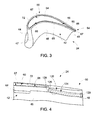
FIG. 3 is a partial perspective upper view of the turbine blade ofFIG. 2 ; -
FIG. 4 is a partial perspective side view of a turbine blade including a squeeler pocket and a bleed passage shown in the form of a bleed conduit in accordance with another aspect of the exemplary embodiment; -
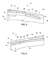
FIG. 5 is a partial perspective side view of a turbine blade including a squeeler pocket and a bleed passage shown in the form of a bleed conduit in accordance with yet another aspect of the exemplary embodiment; and -
FIG. 6 is a partial perspective side view of a turbine blade including a squeeler pocket and a bleed passage shown in the form of a bleed conduit in accordance with still another aspect of the exemplary embodiment. - The detailed description explains embodiments of the invention, together with advantages and features, by way of example with reference to the drawings.
- With reference to
FIG. 1 , a turbomachine in accordance with an exemplary embodiment is indicated generally at 2.Turbomachine 2 includes acompressor portion 4 and aturbine portion 6.Compressor portion 4 is fluidly coupled toturbine portion 6 through acombustor assembly 8.Compressor portion 4 is also mechanically linked toturbine portion 6 via a common compressor/turbine shaft 10.Turbine portion 6 includes a plurality ofturbine stages 14 that extend along ahot gas path 15.Turbine stages 14 include afirst stage 16, asecond stage 18, and athird stage 20. Of course, it should be understood that the number of stages forturbine portion 6 could of course vary.First stage 16 includes a plurality of stators or stationary vanes one of which is indicated at 22, and a plurality of rotating airfoil members or turbine blades one of which is indicated at 24. Likewise,second stage 18 includes a plurality of second stage stators or stationary vanes, one of which is indicated at 26, and second stage rotating airfoil members or turbine blades, one of which is indicated at 28.Third stage 20 includes a plurality of third stage stators or stationary vanes, one of which is indicated at 30, and a plurality of third stage rotating airfoil members or turbine blades, one of which is indicated at 32. - Reference will now be made to
FIGs. 2 and3 in describing firststage turbine blade 24 with an understanding that second and third stage blades 28 and 32 could include similar structure.Turbine blade 24 includes anairfoil portion 42 having asuction side 44 including a suction side contour (not separately labeled), and apressure side 45 having a pressure side contour (also not separately labeled).Suction side 44 andpressure size 45 extend between a leadingedge 47 and atrailing edge 48. In the exemplary embodiment shown,turbine blade 24 includes atip portion 50 provided with asqueeler pocket 60. As will be discussed more fully below,squeeler pocket 60 conditions working fluid flowing overturbine blade 24 to prevent spillage overtip portion 50. Reducing spillage enhances turbomachine efficiency by directing a greater portion of the working fluid onto working surfaces ofturbine portion 6. - In accordance with an exemplary embodiment,
squeeler pocket 60 includes abase wall 64 that is bounded by first andsecond side walls First sidewall 66 includes a firstinner surface 69 having a substantially continuous curvilinear profile. Similarly,second sidewall 67 includes a secondinner surface 72 having a substantially continuous curvilinear profile. More specifically, first inner surface includes a substantially continuous curvilinear profile that substantially mirrors the pressure side contour. Secondinner surface 72 includes a substantially continuous curvilinear profile that substantially mirrors the suction side contour. At this point it should be understood that the phrase "substantially continuous curvilinear profile" should be understood to describe a curvilinear wall having substantially no excursions (bumps and the like) between leadingedge 47 along a path towardtrailing edge 48. - In further accordance with the exemplary embodiment,
tip portion 50 includes ableed passage 84 that extends fromsqueeler pocket 60 to trailingedge 48.Bleed passage 84 is exposed attip portion 50 and includes afirst end portion 85 that extends fromsqueeler pocket 60 to asecond end portion 86. In the exemplary aspect shown,second end portion 86 is provided with anoutlet 87 shown in the form of an opening (not separately labeled) formed intrailing edge 48 attip portion 50.Outlet 87 provides a pathway for working fluid enteringsqueeler pocket 60 toexit tip portion 50 without spilling over onto a working surface. Moreover, by providing a substantially continuous curvilinear profile for first andsecond side walls squeeler pocket 60 is reduced thereby substantially reducing or eliminating spillage or over flow ontopressure side 45 orsuction side 44. The reduction or elimination of overflow increases turbine efficiency. - Reference will now be made to
FIG. 4 , wherein like reference numbers represent corresponding parts in the respective views, in describing ableed passage 120 in accordance with another aspect of the exemplary embodiment.Bleed passage 120 takes the form of a bleedconduit 124 is encapsulated bytip portion 50. More specifically,bleed conduit 124 extends throughairfoil portion 42. More specifically,bleed conduit 124 includes awall section 126 that is completely contained withinairfoil portion 42. With this arrangement, bleedconduit 124 includes a first end orinlet 128 that is open tosqueeler pocket 60 and a second end oroutlet 129 that is open at trailingedge 48. In this manner, working fluid enteringsqueeler pocket 60 enters intobleed conduit 124 throughinlet 128 and is discharged through trailingedge 48 viaoutlet 129. - Reference will now be made to
FIG. 5 , wherein like reference numbers represent corresponding parts in the respective views, in describing ableed passage 140 in accordance with another aspect of the exemplary embodiment. Bleedpassage 140 takes the form of ableed conduit 144 that is encapsulated bytip portion 50. More specifically, bleedconduit 144 extends throughairfoil portion 42. More specifically, bleedconduit 144 includes awall section 146 that is completely contained withinairfoil portion 42. With this arrangement, bleedconduit 144 includes a first end orinlet 148 that is open tosqueeler pocket 60 and a second end oroutlet 149 that is open atpressure side 45. In this manner, working fluid enteringsqueeler pocket 60 enters intobleed conduit 144 throughinlet 148 and is discharged throughpressure side 45 viaoutlet 149. - Reference will now be made to
FIG. 6 , wherein like reference numbers represent corresponding parts in the respective views, in describing ableed passage 160 in accordance with another aspect of the exemplary embodiment. Bleedpassage 160 takes the form of ableed conduit 164 that is encapsulated bytip portion 50. More specifically, bledconduit 164 extends throughairfoil portion 42. More specifically, bleedconduit 164 includes awall section 166 that is completely contained withinairfoil portion 42. With this arrangement, bleedconduit 164 includes a first end orinlet 168 that is open tosqueeler pocket 60 and a second end oroutlet 169 that is open atsuction side 44. In this manner, working fluid enteringsqueeler pocket 60 enters intobleed conduit 164 throughinlet 168 and is discharged throughsuction side 44 viaoutlet 149. - At this point it should be understood that the exemplary embodiments describe a squeeler pocket that is designed to deliver a substantially unobstructed fluid flow to the bleed passage to reduce working fluid spillage over a tip portion of a turbine blade. The substantiality continuous curvilinear side portions of the squeeler pocket reduces abrupt pressure increases resulting from sudden flow area reductions in the bleed passage. The bleed passage directs the fluid from the squeeler pocket through a surface of the turbine blade so as to reduce losses. That is, the working fluid that has passed into the squeeler pocket is guided back into the turbine portion to remix with the working fluid flowing along the hot gas path.
- While the invention has been described in detail in connection with only a limited number of embodiments, it should be readily understood that the invention is not limited to such disclosed embodiments. Rather, the invention can be modified to incorporate any number of variations, alterations, substitutions or equivalent arrangements not heretofore described, but which are commensurate with the spirit and scope of the invention. Additionally, while various embodiments of the invention have been described, it is to be understood that aspects of the invention may include only some of the described embodiments. Accordingly, the invention is not to be seen as limited by the foregoing description, but is only limited by the scope of the appended claims.
Claims (11)
- A turbine blade (24) comprising:an airfoil portion (42) including a suction side (44) having a suction side contour, a pressure side (45) having a pressure side contour, a leading edge (47), a trailing edge (48) and a tip portion (50);a squeeler pocket (60) formed in the tip portion (50), the squeeler pocket (60) including a base wall (64), a first side wall (66) that extends along the pressure side (45) between the leading edge (47) and the trailing edge (48), and a second side wall (67) that extends along the suction side (44) between the leading edge (47) and the trailing edge (48), the first side wall (66) including a first internal surface (69) having a first substantially continuous curvilinear profile, and the second side wall (67) including a second internal surface (72) having a second substantially continuous curvilinear profile; anda bleed passage (84) extending from the squeeler pocket (60) towards the trailing edge (48), wherein the first and second side walls (66,67) are configured to deliver a substantially unobstructed fluid flow from the squeeler pocket (60) to the bleed passage (84) and limit fluid flow spillage onto one of the pressure side (45) and the suction side (44).
- The turbine blade according to claim 1, wherein the first substantially continuous curvilinear profile substantially mirrors the pressure side (45) contour.
- The turbine blade according to claim 1 or 2, wherein the second substantially continuous curvilinear profile substantially mirrors the suction side (44) contour.
- The turbine blade according to any of claims 1 to 3, wherein the bleed passage (84) is exposed at the tip portion (50).
- The turbine blade according to any of claims 1 to 3, wherein the bleed passage (120) comprises a bleed conduit (124) that is encapsulated within the tip portion (50).
- The turbine blade according to any preceding claim, wherein the bleed passage (84) includes an outlet (87, 129) formed in the trailing edge (48).
- The turbine blade according to any of claims 1 to 6, wherein the bleed passage (120) comprises a bleed conduit (124) that extends from the squeeler pocket (60) toward the trailing edge (48) through the airfoil portion (42).
- The turbine blade according to claim 7, wherein the bleed conduit (124) includes an inlet section (128) exposed at the squeeler pocket (60) and an outlet section (129) that extends through the trailing edge (48) of the airfoil portion (42).
- The turbine blade according to claim 7, wherein the bleed conduit (164) includes an inlet section (168) exposed at the squeeler pocket (60) and an outlet section (169) that extends through the suction side (44) of the airfoil portion (42).
- The turbine blade according to claim 7, wherein the bleed conduit (144) includes an inlet section (148) exposed at the squeeler pocket (60) and an outlet section (149) that extends through the pressure side (45) of the airfoil portion (42).
- A turbomachine comprising:a compressor portion (4);a combustor assembly (8) fluidly coupled to the compressor portion (4); anda turbine portion (6) operatively coupled to the compressor portion (4) and fluidly connected to the combustor assembly (8), the turbine portion (6) including a turbine blade (24) as recited in any of claims 1 to 10.
Applications Claiming Priority (1)
| Application Number | Priority Date | Filing Date | Title |
|---|---|---|---|
| US13/284,010 US9051843B2 (en) | 2011-10-28 | 2011-10-28 | Turbomachine blade including a squeeler pocket |
Publications (3)
| Publication Number | Publication Date |
|---|---|
| EP2586984A2 true EP2586984A2 (en) | 2013-05-01 |
| EP2586984A3 EP2586984A3 (en) | 2014-06-11 |
| EP2586984B1 EP2586984B1 (en) | 2020-02-19 |
Family
ID=47073346
Family Applications (1)
| Application Number | Title | Priority Date | Filing Date |
|---|---|---|---|
| EP12189881.1A Active EP2586984B1 (en) | 2011-10-28 | 2012-10-25 | Turbine rotor blade and corresponding turbomachine |
Country Status (3)
| Country | Link |
|---|---|
| US (1) | US9051843B2 (en) |
| EP (1) | EP2586984B1 (en) |
| CN (1) | CN103089320B (en) |
Cited By (1)
| Publication number | Priority date | Publication date | Assignee | Title |
|---|---|---|---|---|
| EP3088675A1 (en) * | 2015-04-29 | 2016-11-02 | General Electric Company | Rotor blade having a flared tip and corresponding gas turbine |
Families Citing this family (4)
| Publication number | Priority date | Publication date | Assignee | Title |
|---|---|---|---|---|
| US20160245095A1 (en) * | 2015-02-25 | 2016-08-25 | General Electric Company | Turbine rotor blade |
| US10443405B2 (en) * | 2017-05-10 | 2019-10-15 | General Electric Company | Rotor blade tip |
| US11644046B2 (en) * | 2018-01-05 | 2023-05-09 | Aurora Flight Sciences Corporation | Composite fan blades with integral attachment mechanism |
| US12123319B2 (en) | 2020-12-30 | 2024-10-22 | Ge Infrastructure Technology Llc | Cooling circuit having a bypass conduit for a turbomachine component |
Family Cites Families (61)
| Publication number | Priority date | Publication date | Assignee | Title |
|---|---|---|---|---|
| US891383A (en) | 1907-12-09 | 1908-06-23 | Gen Electric | Elastic-fluid turbine. |
| US2392673A (en) | 1943-08-27 | 1946-01-08 | Gen Electric | Elastic fluid turbine |
| US2795373A (en) | 1950-03-03 | 1957-06-11 | Rolls Royce | Guide vane assemblies in annular fluid ducts |
| US3635585A (en) | 1969-12-23 | 1972-01-18 | Westinghouse Electric Corp | Gas-cooled turbine blade |
| US3854842A (en) | 1973-04-30 | 1974-12-17 | Gen Electric | Rotor blade having improved tip cap |
| US4194869A (en) | 1978-06-29 | 1980-03-25 | United Technologies Corporation | Stator vane cluster |
| DE3202855C1 (en) | 1982-01-29 | 1983-03-31 | MTU Motoren- und Turbinen-Union München GmbH, 8000 München | Device for reducing secondary flow losses in a bladed flow channel |
| US4741667A (en) | 1986-05-28 | 1988-05-03 | United Technologies Corporation | Stator vane |
| US5397215A (en) | 1993-06-14 | 1995-03-14 | United Technologies Corporation | Flow directing assembly for the compression section of a rotary machine |
| GB2281356B (en) | 1993-08-20 | 1997-01-29 | Rolls Royce Plc | Gas turbine engine turbine |
| US5326221A (en) | 1993-08-27 | 1994-07-05 | General Electric Company | Over-cambered stage design for steam turbines |
| US5375972A (en) | 1993-09-16 | 1994-12-27 | The United States Of America As Represented By The Secretary Of The Air Force | Turbine stator vane structure |
| US5525038A (en) | 1994-11-04 | 1996-06-11 | United Technologies Corporation | Rotor airfoils to control tip leakage flows |
| US5581996A (en) | 1995-08-16 | 1996-12-10 | General Electric Company | Method and apparatus for turbine cooling |
| JPH10184304A (en) | 1996-12-27 | 1998-07-14 | Toshiba Corp | Axial turbine turbine nozzles and turbine blades |
| US5927946A (en) * | 1997-09-29 | 1999-07-27 | General Electric Company | Turbine blade having recuperative trailing edge tip cooling |
| JP2000045704A (en) | 1998-07-31 | 2000-02-15 | Toshiba Corp | Steam turbine |
| US6077036A (en) | 1998-08-20 | 2000-06-20 | General Electric Company | Bowed nozzle vane with selective TBC |
| GB9823840D0 (en) | 1998-10-30 | 1998-12-23 | Rolls Royce Plc | Bladed ducting for turbomachinery |
| US6224336B1 (en) | 1999-06-09 | 2001-05-01 | General Electric Company | Triple tip-rib airfoil |
| GB0003676D0 (en) | 2000-02-17 | 2000-04-05 | Abb Alstom Power Nv | Aerofoils |
| US6561761B1 (en) | 2000-02-18 | 2003-05-13 | General Electric Company | Fluted compressor flowpath |
| US6709223B2 (en) | 2000-04-27 | 2004-03-23 | The Toro Company | Tracked compact utility loader |
| JP3912989B2 (en) | 2001-01-25 | 2007-05-09 | 三菱重工業株式会社 | gas turbine |
| US6478537B2 (en) | 2001-02-16 | 2002-11-12 | Siemens Westinghouse Power Corporation | Pre-segmented squealer tip for turbine blades |
| JP4373629B2 (en) | 2001-08-31 | 2009-11-25 | 株式会社東芝 | Axial flow turbine |
| WO2003052240A2 (en) | 2001-12-14 | 2003-06-26 | Alstom Technology Ltd | Gas turbine system |
| GB2384276A (en) | 2002-01-18 | 2003-07-23 | Alstom | Gas turbine low pressure stage |
| US6669445B2 (en) | 2002-03-07 | 2003-12-30 | United Technologies Corporation | Endwall shape for use in turbomachinery |
| US6969232B2 (en) | 2002-10-23 | 2005-11-29 | United Technologies Corporation | Flow directing device |
| GB0319002D0 (en) | 2003-05-13 | 2003-09-17 | Alstom Switzerland Ltd | Improvements in or relating to steam turbines |
| ITMI20040712A1 (en) | 2004-04-09 | 2004-07-09 | Nuovo Pignone Spa | ROTOR AND HIGH EFFICIENCY FOR A SECOND STAGE, A GAS TURBINE |
| US7547187B2 (en) | 2005-03-31 | 2009-06-16 | Hitachi, Ltd. | Axial turbine |
| US7195454B2 (en) | 2004-12-02 | 2007-03-27 | General Electric Company | Bullnose step turbine nozzle |
| US7134842B2 (en) | 2004-12-24 | 2006-11-14 | General Electric Company | Scalloped surface turbine stage |
| EP1710397B1 (en) | 2005-03-31 | 2014-06-11 | Kabushiki Kaisha Toshiba | Bowed nozzle vane |
| US7244104B2 (en) | 2005-05-31 | 2007-07-17 | Pratt & Whitney Canada Corp. | Deflectors for controlling entry of fluid leakage into the working fluid flowpath of a gas turbine engine |
| US7465152B2 (en) | 2005-09-16 | 2008-12-16 | General Electric Company | Angel wing seals for turbine blades and methods for selecting stator, rotor and wing seal profiles |
| US8511978B2 (en) | 2006-05-02 | 2013-08-20 | United Technologies Corporation | Airfoil array with an endwall depression and components of the array |
| US7887297B2 (en) | 2006-05-02 | 2011-02-15 | United Technologies Corporation | Airfoil array with an endwall protrusion and components of the array |
| US7607893B2 (en) | 2006-08-21 | 2009-10-27 | General Electric Company | Counter tip baffle airfoil |
| US7549844B2 (en) * | 2006-08-24 | 2009-06-23 | Siemens Energy, Inc. | Turbine airfoil cooling system with bifurcated and recessed trailing edge exhaust channels |
| US7520728B2 (en) | 2006-09-07 | 2009-04-21 | Pratt & Whitney Canada Corp. | HP turbine vane airfoil profile |
| US7845906B2 (en) * | 2007-01-24 | 2010-12-07 | United Technologies Corporation | Dual cut-back trailing edge for airfoils |
| US7740449B1 (en) | 2007-01-26 | 2010-06-22 | Florida Turbine Technologies, Inc. | Process for adjusting a flow capacity of an airfoil |
| US7632075B2 (en) | 2007-02-15 | 2009-12-15 | Siemens Energy, Inc. | External profile for turbine blade airfoil |
| JP5283855B2 (en) | 2007-03-29 | 2013-09-04 | 株式会社Ihi | Turbomachine wall and turbomachine |
| US8011889B1 (en) * | 2007-09-07 | 2011-09-06 | Florida Turbine Technologies, Inc. | Turbine blade with trailing edge tip corner cooling |
| GB0724612D0 (en) | 2007-12-19 | 2008-01-30 | Rolls Royce Plc | Rotor blades |
| US8313291B2 (en) | 2007-12-19 | 2012-11-20 | Nuovo Pignone, S.P.A. | Turbine inlet guide vane with scalloped platform and related method |
| JP5291355B2 (en) | 2008-02-12 | 2013-09-18 | 三菱重工業株式会社 | Turbine cascade endwall |
| DE102008029605A1 (en) | 2008-06-23 | 2009-12-24 | Rolls-Royce Deutschland Ltd & Co Kg | Bucket cover tape with passage |
| GB0813556D0 (en) * | 2008-07-24 | 2008-09-03 | Rolls Royce Plc | A blade for a rotor |
| US8419356B2 (en) | 2008-09-25 | 2013-04-16 | Siemens Energy, Inc. | Turbine seal assembly |
| US8459956B2 (en) * | 2008-12-24 | 2013-06-11 | General Electric Company | Curved platform turbine blade |
| US8083484B2 (en) * | 2008-12-26 | 2011-12-27 | General Electric Company | Turbine rotor blade tips that discourage cross-flow |
| US8105037B2 (en) | 2009-04-06 | 2012-01-31 | United Technologies Corporation | Endwall with leading-edge hump |
| US8286430B2 (en) | 2009-05-28 | 2012-10-16 | General Electric Company | Steam turbine two flow low pressure configuration |
| US8342797B2 (en) * | 2009-08-31 | 2013-01-01 | Rolls-Royce North American Technologies Inc. | Cooled gas turbine engine airflow member |
| US9039375B2 (en) | 2009-09-01 | 2015-05-26 | General Electric Company | Non-axisymmetric airfoil platform shaping |
| US8721291B2 (en) | 2011-07-12 | 2014-05-13 | Siemens Energy, Inc. | Flow directing member for gas turbine engine |
-
2011
- 2011-10-28 US US13/284,010 patent/US9051843B2/en active Active
-
2012
- 2012-10-25 EP EP12189881.1A patent/EP2586984B1/en active Active
- 2012-10-26 CN CN201210417460.5A patent/CN103089320B/en active Active
Non-Patent Citations (1)
| Title |
|---|
| None |
Cited By (2)
| Publication number | Priority date | Publication date | Assignee | Title |
|---|---|---|---|---|
| EP3088675A1 (en) * | 2015-04-29 | 2016-11-02 | General Electric Company | Rotor blade having a flared tip and corresponding gas turbine |
| US10107108B2 (en) | 2015-04-29 | 2018-10-23 | General Electric Company | Rotor blade having a flared tip |
Also Published As
| Publication number | Publication date |
|---|---|
| EP2586984B1 (en) | 2020-02-19 |
| CN103089320B (en) | 2016-07-06 |
| US20130108444A1 (en) | 2013-05-02 |
| US9051843B2 (en) | 2015-06-09 |
| CN103089320A (en) | 2013-05-08 |
| EP2586984A3 (en) | 2014-06-11 |
Similar Documents
| Publication | Publication Date | Title |
|---|---|---|
| CN111677556B (en) | Fillet optimization for turbine airfoils | |
| EP2374997B1 (en) | Component for a gas turbine engine | |
| US10774659B2 (en) | Tip leakage flow directionality control | |
| EP2581555A1 (en) | Turbomachine Component having a Flow Contour Feature | |
| EP2597263B1 (en) | Bucket assembly for turbine system | |
| US10815790B2 (en) | Tip leakage flow directionality control | |
| CN107013329B (en) | Airfoils for gas turbine engines | |
| EP2597260A1 (en) | Bucket assembly for turbine system | |
| CN106988789A (en) | The engine component cooled down with film | |
| EP2586984B1 (en) | Turbine rotor blade and corresponding turbomachine | |
| EP2551458A2 (en) | Blade Cooling and Sealing System | |
| US20090169360A1 (en) | Turbine Nozzle Segment | |
| JP2019007478A (en) | Rotor blade tip | |
| EP3214269A1 (en) | Airfoil for a gas turbine engine | |
| CN102652207B (en) | Guide vanes with wing lifts for energy conversion machines and machines for converting energy comprising guide vanes | |
| WO2014164888A1 (en) | Low pressure loss cooled blade | |
| EP2597262B1 (en) | Bucket assembly for turbine system | |
| GB2467350A (en) | Cooling and sealing in gas turbine engine turbine stage | |
| US10612389B2 (en) | Engine component with porous section | |
| EP3205824A1 (en) | Accelerator insert for a gas turbine engine airfoil | |
| US11788417B2 (en) | Turbine blade and gas turbine | |
| US10508548B2 (en) | Turbine engine with a platform cooling circuit | |
| EP3090130A2 (en) | Tip leakage flow directionality control |
Legal Events
| Date | Code | Title | Description |
|---|---|---|---|
| PUAI | Public reference made under article 153(3) epc to a published international application that has entered the european phase |
Free format text: ORIGINAL CODE: 0009012 |
|
| AK | Designated contracting states |
Kind code of ref document: A2 Designated state(s): AL AT BE BG CH CY CZ DE DK EE ES FI FR GB GR HR HU IE IS IT LI LT LU LV MC MK MT NL NO PL PT RO RS SE SI SK SM TR |
|
| AX | Request for extension of the european patent |
Extension state: BA ME |
|
| PUAL | Search report despatched |
Free format text: ORIGINAL CODE: 0009013 |
|
| AK | Designated contracting states |
Kind code of ref document: A3 Designated state(s): AL AT BE BG CH CY CZ DE DK EE ES FI FR GB GR HR HU IE IS IT LI LT LU LV MC MK MT NL NO PL PT RO RS SE SI SK SM TR |
|
| AX | Request for extension of the european patent |
Extension state: BA ME |
|
| RIC1 | Information provided on ipc code assigned before grant |
Ipc: F01D 5/20 20060101AFI20140507BHEP |
|
| 17P | Request for examination filed |
Effective date: 20141211 |
|
| RBV | Designated contracting states (corrected) |
Designated state(s): AL AT BE BG CH CY CZ DE DK EE ES FI FR GB GR HR HU IE IS IT LI LT LU LV MC MK MT NL NO PL PT RO RS SE SI SK SM TR |
|
| GRAP | Despatch of communication of intention to grant a patent |
Free format text: ORIGINAL CODE: EPIDOSNIGR1 |
|
| STAA | Information on the status of an ep patent application or granted ep patent |
Free format text: STATUS: GRANT OF PATENT IS INTENDED |
|
| INTG | Intention to grant announced |
Effective date: 20190805 |
|
| GRAS | Grant fee paid |
Free format text: ORIGINAL CODE: EPIDOSNIGR3 |
|
| GRAJ | Information related to disapproval of communication of intention to grant by the applicant or resumption of examination proceedings by the epo deleted |
Free format text: ORIGINAL CODE: EPIDOSDIGR1 |
|
| GRAL | Information related to payment of fee for publishing/printing deleted |
Free format text: ORIGINAL CODE: EPIDOSDIGR3 |
|
| STAA | Information on the status of an ep patent application or granted ep patent |
Free format text: STATUS: REQUEST FOR EXAMINATION WAS MADE |
|
| GRAR | Information related to intention to grant a patent recorded |
Free format text: ORIGINAL CODE: EPIDOSNIGR71 |
|
| STAA | Information on the status of an ep patent application or granted ep patent |
Free format text: STATUS: GRANT OF PATENT IS INTENDED |
|
| GRAA | (expected) grant |
Free format text: ORIGINAL CODE: 0009210 |
|
| STAA | Information on the status of an ep patent application or granted ep patent |
Free format text: STATUS: THE PATENT HAS BEEN GRANTED |
|
| INTC | Intention to grant announced (deleted) | ||
| AK | Designated contracting states |
Kind code of ref document: B1 Designated state(s): AL AT BE BG CH CY CZ DE DK EE ES FI FR GB GR HR HU IE IS IT LI LT LU LV MC MK MT NL NO PL PT RO RS SE SI SK SM TR |
|
| INTG | Intention to grant announced |
Effective date: 20200113 |
|
| REG | Reference to a national code |
Ref country code: GB Ref legal event code: FG4D |
|
| REG | Reference to a national code |
Ref country code: CH Ref legal event code: EP |
|
| REG | Reference to a national code |
Ref country code: DE Ref legal event code: R096 Ref document number: 602012067856 Country of ref document: DE |
|
| REG | Reference to a national code |
Ref country code: AT Ref legal event code: REF Ref document number: 1235186 Country of ref document: AT Kind code of ref document: T Effective date: 20200315 |
|
| REG | Reference to a national code |
Ref country code: IE Ref legal event code: FG4D |
|
| REG | Reference to a national code |
Ref country code: NL Ref legal event code: MP Effective date: 20200219 |
|
| PG25 | Lapsed in a contracting state [announced via postgrant information from national office to epo] |
Ref country code: NO Free format text: LAPSE BECAUSE OF FAILURE TO SUBMIT A TRANSLATION OF THE DESCRIPTION OR TO PAY THE FEE WITHIN THE PRESCRIBED TIME-LIMIT Effective date: 20200519 Ref country code: RS Free format text: LAPSE BECAUSE OF FAILURE TO SUBMIT A TRANSLATION OF THE DESCRIPTION OR TO PAY THE FEE WITHIN THE PRESCRIBED TIME-LIMIT Effective date: 20200219 Ref country code: FI Free format text: LAPSE BECAUSE OF FAILURE TO SUBMIT A TRANSLATION OF THE DESCRIPTION OR TO PAY THE FEE WITHIN THE PRESCRIBED TIME-LIMIT Effective date: 20200219 |
|
| REG | Reference to a national code |
Ref country code: LT Ref legal event code: MG4D |
|
| PG25 | Lapsed in a contracting state [announced via postgrant information from national office to epo] |
Ref country code: IS Free format text: LAPSE BECAUSE OF FAILURE TO SUBMIT A TRANSLATION OF THE DESCRIPTION OR TO PAY THE FEE WITHIN THE PRESCRIBED TIME-LIMIT Effective date: 20200619 Ref country code: SE Free format text: LAPSE BECAUSE OF FAILURE TO SUBMIT A TRANSLATION OF THE DESCRIPTION OR TO PAY THE FEE WITHIN THE PRESCRIBED TIME-LIMIT Effective date: 20200219 Ref country code: LV Free format text: LAPSE BECAUSE OF FAILURE TO SUBMIT A TRANSLATION OF THE DESCRIPTION OR TO PAY THE FEE WITHIN THE PRESCRIBED TIME-LIMIT Effective date: 20200219 Ref country code: GR Free format text: LAPSE BECAUSE OF FAILURE TO SUBMIT A TRANSLATION OF THE DESCRIPTION OR TO PAY THE FEE WITHIN THE PRESCRIBED TIME-LIMIT Effective date: 20200520 Ref country code: BG Free format text: LAPSE BECAUSE OF FAILURE TO SUBMIT A TRANSLATION OF THE DESCRIPTION OR TO PAY THE FEE WITHIN THE PRESCRIBED TIME-LIMIT Effective date: 20200519 Ref country code: HR Free format text: LAPSE BECAUSE OF FAILURE TO SUBMIT A TRANSLATION OF THE DESCRIPTION OR TO PAY THE FEE WITHIN THE PRESCRIBED TIME-LIMIT Effective date: 20200219 |
|
| PG25 | Lapsed in a contracting state [announced via postgrant information from national office to epo] |
Ref country code: NL Free format text: LAPSE BECAUSE OF FAILURE TO SUBMIT A TRANSLATION OF THE DESCRIPTION OR TO PAY THE FEE WITHIN THE PRESCRIBED TIME-LIMIT Effective date: 20200219 |
|
| PG25 | Lapsed in a contracting state [announced via postgrant information from national office to epo] |
Ref country code: LT Free format text: LAPSE BECAUSE OF FAILURE TO SUBMIT A TRANSLATION OF THE DESCRIPTION OR TO PAY THE FEE WITHIN THE PRESCRIBED TIME-LIMIT Effective date: 20200219 Ref country code: ES Free format text: LAPSE BECAUSE OF FAILURE TO SUBMIT A TRANSLATION OF THE DESCRIPTION OR TO PAY THE FEE WITHIN THE PRESCRIBED TIME-LIMIT Effective date: 20200219 Ref country code: EE Free format text: LAPSE BECAUSE OF FAILURE TO SUBMIT A TRANSLATION OF THE DESCRIPTION OR TO PAY THE FEE WITHIN THE PRESCRIBED TIME-LIMIT Effective date: 20200219 Ref country code: DK Free format text: LAPSE BECAUSE OF FAILURE TO SUBMIT A TRANSLATION OF THE DESCRIPTION OR TO PAY THE FEE WITHIN THE PRESCRIBED TIME-LIMIT Effective date: 20200219 Ref country code: SM Free format text: LAPSE BECAUSE OF FAILURE TO SUBMIT A TRANSLATION OF THE DESCRIPTION OR TO PAY THE FEE WITHIN THE PRESCRIBED TIME-LIMIT Effective date: 20200219 Ref country code: PT Free format text: LAPSE BECAUSE OF FAILURE TO SUBMIT A TRANSLATION OF THE DESCRIPTION OR TO PAY THE FEE WITHIN THE PRESCRIBED TIME-LIMIT Effective date: 20200712 Ref country code: SK Free format text: LAPSE BECAUSE OF FAILURE TO SUBMIT A TRANSLATION OF THE DESCRIPTION OR TO PAY THE FEE WITHIN THE PRESCRIBED TIME-LIMIT Effective date: 20200219 Ref country code: RO Free format text: LAPSE BECAUSE OF FAILURE TO SUBMIT A TRANSLATION OF THE DESCRIPTION OR TO PAY THE FEE WITHIN THE PRESCRIBED TIME-LIMIT Effective date: 20200219 Ref country code: CZ Free format text: LAPSE BECAUSE OF FAILURE TO SUBMIT A TRANSLATION OF THE DESCRIPTION OR TO PAY THE FEE WITHIN THE PRESCRIBED TIME-LIMIT Effective date: 20200219 |
|
| REG | Reference to a national code |
Ref country code: AT Ref legal event code: MK05 Ref document number: 1235186 Country of ref document: AT Kind code of ref document: T Effective date: 20200219 |
|
| REG | Reference to a national code |
Ref country code: DE Ref legal event code: R097 Ref document number: 602012067856 Country of ref document: DE |
|
| PLBE | No opposition filed within time limit |
Free format text: ORIGINAL CODE: 0009261 |
|
| STAA | Information on the status of an ep patent application or granted ep patent |
Free format text: STATUS: NO OPPOSITION FILED WITHIN TIME LIMIT |
|
| 26N | No opposition filed |
Effective date: 20201120 |
|
| PG25 | Lapsed in a contracting state [announced via postgrant information from national office to epo] |
Ref country code: AT Free format text: LAPSE BECAUSE OF FAILURE TO SUBMIT A TRANSLATION OF THE DESCRIPTION OR TO PAY THE FEE WITHIN THE PRESCRIBED TIME-LIMIT Effective date: 20200219 |
|
| PG25 | Lapsed in a contracting state [announced via postgrant information from national office to epo] |
Ref country code: SI Free format text: LAPSE BECAUSE OF FAILURE TO SUBMIT A TRANSLATION OF THE DESCRIPTION OR TO PAY THE FEE WITHIN THE PRESCRIBED TIME-LIMIT Effective date: 20200219 Ref country code: PL Free format text: LAPSE BECAUSE OF FAILURE TO SUBMIT A TRANSLATION OF THE DESCRIPTION OR TO PAY THE FEE WITHIN THE PRESCRIBED TIME-LIMIT Effective date: 20200219 |
|
| REG | Reference to a national code |
Ref country code: CH Ref legal event code: PL |
|
| GBPC | Gb: european patent ceased through non-payment of renewal fee |
Effective date: 20201025 |
|
| PG25 | Lapsed in a contracting state [announced via postgrant information from national office to epo] |
Ref country code: LU Free format text: LAPSE BECAUSE OF NON-PAYMENT OF DUE FEES Effective date: 20201025 Ref country code: MC Free format text: LAPSE BECAUSE OF FAILURE TO SUBMIT A TRANSLATION OF THE DESCRIPTION OR TO PAY THE FEE WITHIN THE PRESCRIBED TIME-LIMIT Effective date: 20200219 |
|
| REG | Reference to a national code |
Ref country code: BE Ref legal event code: MM Effective date: 20201031 |
|
| PG25 | Lapsed in a contracting state [announced via postgrant information from national office to epo] |
Ref country code: FR Free format text: LAPSE BECAUSE OF NON-PAYMENT OF DUE FEES Effective date: 20201031 |
|
| PG25 | Lapsed in a contracting state [announced via postgrant information from national office to epo] |
Ref country code: LI Free format text: LAPSE BECAUSE OF NON-PAYMENT OF DUE FEES Effective date: 20201031 Ref country code: GB Free format text: LAPSE BECAUSE OF NON-PAYMENT OF DUE FEES Effective date: 20201025 Ref country code: BE Free format text: LAPSE BECAUSE OF NON-PAYMENT OF DUE FEES Effective date: 20201031 Ref country code: CH Free format text: LAPSE BECAUSE OF NON-PAYMENT OF DUE FEES Effective date: 20201031 |
|
| PG25 | Lapsed in a contracting state [announced via postgrant information from national office to epo] |
Ref country code: IE Free format text: LAPSE BECAUSE OF NON-PAYMENT OF DUE FEES Effective date: 20201025 |
|
| PG25 | Lapsed in a contracting state [announced via postgrant information from national office to epo] |
Ref country code: TR Free format text: LAPSE BECAUSE OF FAILURE TO SUBMIT A TRANSLATION OF THE DESCRIPTION OR TO PAY THE FEE WITHIN THE PRESCRIBED TIME-LIMIT Effective date: 20200219 Ref country code: MT Free format text: LAPSE BECAUSE OF FAILURE TO SUBMIT A TRANSLATION OF THE DESCRIPTION OR TO PAY THE FEE WITHIN THE PRESCRIBED TIME-LIMIT Effective date: 20200219 Ref country code: CY Free format text: LAPSE BECAUSE OF FAILURE TO SUBMIT A TRANSLATION OF THE DESCRIPTION OR TO PAY THE FEE WITHIN THE PRESCRIBED TIME-LIMIT Effective date: 20200219 |
|
| PG25 | Lapsed in a contracting state [announced via postgrant information from national office to epo] |
Ref country code: MK Free format text: LAPSE BECAUSE OF FAILURE TO SUBMIT A TRANSLATION OF THE DESCRIPTION OR TO PAY THE FEE WITHIN THE PRESCRIBED TIME-LIMIT Effective date: 20200219 Ref country code: AL Free format text: LAPSE BECAUSE OF FAILURE TO SUBMIT A TRANSLATION OF THE DESCRIPTION OR TO PAY THE FEE WITHIN THE PRESCRIBED TIME-LIMIT Effective date: 20200219 |
|
| REG | Reference to a national code |
Ref country code: DE Ref legal event code: R082 Ref document number: 602012067856 Country of ref document: DE Ref country code: DE Ref legal event code: R081 Ref document number: 602012067856 Country of ref document: DE Owner name: GENERAL ELECTRIC TECHNOLOGY GMBH, CH Free format text: FORMER OWNER: GENERAL ELECTRIC COMPANY, SCHENECTADY, NY, US |
|
| PGFP | Annual fee paid to national office [announced via postgrant information from national office to epo] |
Ref country code: IT Payment date: 20250923 Year of fee payment: 14 |
|
| PGFP | Annual fee paid to national office [announced via postgrant information from national office to epo] |
Ref country code: DE Payment date: 20250923 Year of fee payment: 14 |