EP2586890A1 - Pipe for evacuating gas and related evacuation method - Google Patents
Pipe for evacuating gas and related evacuation method Download PDFInfo
- Publication number
- EP2586890A1 EP2586890A1 EP11187034.1A EP11187034A EP2586890A1 EP 2586890 A1 EP2586890 A1 EP 2586890A1 EP 11187034 A EP11187034 A EP 11187034A EP 2586890 A1 EP2586890 A1 EP 2586890A1
- Authority
- EP
- European Patent Office
- Prior art keywords
- gas
- evacuation
- inert gas
- reactor
- injection
- Prior art date
- Legal status (The legal status is an assumption and is not a legal conclusion. Google has not performed a legal analysis and makes no representation as to the accuracy of the status listed.)
- Withdrawn
Links
Images


Classifications
-
- C—CHEMISTRY; METALLURGY
- C23—COATING METALLIC MATERIAL; COATING MATERIAL WITH METALLIC MATERIAL; CHEMICAL SURFACE TREATMENT; DIFFUSION TREATMENT OF METALLIC MATERIAL; COATING BY VACUUM EVAPORATION, BY SPUTTERING, BY ION IMPLANTATION OR BY CHEMICAL VAPOUR DEPOSITION, IN GENERAL; INHIBITING CORROSION OF METALLIC MATERIAL OR INCRUSTATION IN GENERAL
- C23C—COATING METALLIC MATERIAL; COATING MATERIAL WITH METALLIC MATERIAL; SURFACE TREATMENT OF METALLIC MATERIAL BY DIFFUSION INTO THE SURFACE, BY CHEMICAL CONVERSION OR SUBSTITUTION; COATING BY VACUUM EVAPORATION, BY SPUTTERING, BY ION IMPLANTATION OR BY CHEMICAL VAPOUR DEPOSITION, IN GENERAL
- C23C16/00—Chemical coating by decomposition of gaseous compounds, without leaving reaction products of surface material in the coating, i.e. chemical vapour deposition [CVD] processes
- C23C16/44—Chemical coating by decomposition of gaseous compounds, without leaving reaction products of surface material in the coating, i.e. chemical vapour deposition [CVD] processes characterised by the method of coating
- C23C16/4412—Details relating to the exhausts, e.g. pumps, filters, scrubbers, particle traps
-
- C—CHEMISTRY; METALLURGY
- C23—COATING METALLIC MATERIAL; COATING MATERIAL WITH METALLIC MATERIAL; CHEMICAL SURFACE TREATMENT; DIFFUSION TREATMENT OF METALLIC MATERIAL; COATING BY VACUUM EVAPORATION, BY SPUTTERING, BY ION IMPLANTATION OR BY CHEMICAL VAPOUR DEPOSITION, IN GENERAL; INHIBITING CORROSION OF METALLIC MATERIAL OR INCRUSTATION IN GENERAL
- C23C—COATING METALLIC MATERIAL; COATING MATERIAL WITH METALLIC MATERIAL; SURFACE TREATMENT OF METALLIC MATERIAL BY DIFFUSION INTO THE SURFACE, BY CHEMICAL CONVERSION OR SUBSTITUTION; COATING BY VACUUM EVAPORATION, BY SPUTTERING, BY ION IMPLANTATION OR BY CHEMICAL VAPOUR DEPOSITION, IN GENERAL
- C23C16/00—Chemical coating by decomposition of gaseous compounds, without leaving reaction products of surface material in the coating, i.e. chemical vapour deposition [CVD] processes
- C23C16/44—Chemical coating by decomposition of gaseous compounds, without leaving reaction products of surface material in the coating, i.e. chemical vapour deposition [CVD] processes characterised by the method of coating
- C23C16/455—Chemical coating by decomposition of gaseous compounds, without leaving reaction products of surface material in the coating, i.e. chemical vapour deposition [CVD] processes characterised by the method of coating characterised by the method used for introducing gases into reaction chamber or for modifying gas flows in reaction chamber
- C23C16/45523—Pulsed gas flow or change of composition over time
- C23C16/45525—Atomic layer deposition [ALD]
- C23C16/45544—Atomic layer deposition [ALD] characterized by the apparatus
Definitions
- the present invention relates to the evacuation of gases from a reactor and more particularly the evacuation of reactive gas residues at the outlet of a chemical reactor such as the reactor of an atomic layer deposition equipment.
- the solutions of the state of the art correspond to the use of two separate vacuum pumps, each being dedicated to a reactive gas.
- the transmission to one or the other of the vacuum pumps being carried out by a system of mechanical valves at the entrance of the an evacuation pipe directing the reactive gas towards one or the other of the evacuation routes of the pipe to which the vacuum pumps are connected.
- the mixing of the reactive gases can occur at the mechanical valves, resulting in the deposition of a by-product layer at the valves which can disrupt their operation and lead to failure.
- the object of the invention is therefore to provide a device for preventing a mixing of the reactive gases at the moving mechanical elements in order to prevent the formation of by-products that can lead to a malfunction and also allowing an orientation. reactive gas from one evacuation route to another evacuation route in a more rapid manner and thus more suitable for pulsed processes such as the atomic layer deposition process.
- the term "conductance" of a pipe is the quotient of the flow divided by the pressure difference upstream and downstream of the pipe and corresponds to the ease of flow of a fluid in the pipe. pipe.
- the embodiments of the present invention relate to the use of an inert gas at a reactant gas evacuation pipe from a reactor, for example an atomic layer deposition reactor, comprising at least two channels discharge pipe to direct the reactive gas to evacuate towards one of the evacuation routes.
- the figure 1 represents a first embodiment of an evacuation pipe.
- the pipe comprises an inlet 1 intended to be connected to the outlet of a reactor in order to receive the residues of two reactive gases, or two different mixtures of reactive gases, coming from the reactor, two evacuation routes 3 and 5 connected each a vacuum pump 7 and 9 and a central trunk 11 connecting the inlet 1 of the pipe to the two evacuation routes 3 and 5.
- the evacuation routes being made to obtain a conductance, for example having similar dimensions and a similar pumping capacity having the same order of magnitude.
- each evacuation route comprises respectively first and second means for injecting an inert gas 13 and 15.
- injector means 13 and 15 may for example comprise a first 17 and a second valve 18 to pass through. or block the inert gas and a first 19 and a second injection nozzle to diffuse the inert gas in the selected direction, in the opposite direction to the direction of pumping (that is to say against the direction of the direction of propagation of the reactive gas in the escape route).
- the injection of inert gas 21 counter-clockwise in one of the evacuation routes makes it possible to direct the reactive gas towards the other evacuation route as shown in FIG. figure 2 .
- the first injection means 13 of inert gas 21 of the first escape route 3 are activated (by the opening of the first valve 17) to constrain the residues of reactive gas G2 to go to the second escape route 5 to be transmitted to the second vacuum pump 9, the latter being dedicated to the pumping of the reactive gas G2.
- the second injection means 15 of inert gas 21 of the second escape route 5 remain inactivated (second valve 18 closed).
- the inert gas may be, for example, N 2 nitrogen, Ar argon or Helium He.
- the second injection means 15 of an inert gas 21 of the second escape route 5 are activated, whereas the injection means 13 of a inert gas 21 of the first evacuation route 3 are deactivated.
- the gas G1 is thus directed to the first vacuum pump 7 dedicated to pumping the gas G1.
- the two gases G1 and G2 are generally injected alternately into the reactor so that the activation of the first and second second inert gas injection means 13 and 15 is also performed alternately depending on the reactive gas G1 or G2 present in the reactor.
- the quantity of inert gas 21 injected can be adjusted according to the amount of reactive gas G1 or G2 to be discharged and the desired reactive gas concentration G1 or G2 at the vacuum pump 7 or 9.
- the amount of inert gas 21 is the same for the two alternation injection sequences so as not to modify the pressure inside the reactor and the pipe.
- the quantity of inert gas injected is calculated to obtain a concentration of 20% of reactive gas G1 or G2 in the gaseous mixture at the level of the vacuum pump, the gaseous mixture at the level of the vacuum pump being composed of reactive gas G1, G2 and injected inert gas 21. It is considered that the outlet concentration of the reactive gas gas G1 or G2 is 100%.
- this concentration of reactive gas G1 or G2 at the vacuum pump can be reduced to 1%.
- the first and second injection means 13 and 15 do not completely block the passage of the inert gas 21 when they are inactive, but are put in a standby mode in which a small amount of gas inert 21 continues to be injected to prevent deposit formation on the injection nozzles 19 and 20 of the inert gas, thereby protecting the injection nozzles 19 and 20.
- valves 23 and 25 are located at the outlet of the evacuation routes 3 and 5 and at the inlet of the vacuum pumps 7 and 9. These valves 23 and 25 are automatic valves which remain open continuously in operation.
- the figure 3 presents a second embodiment of the present invention in the case where the number of escape routes is equal to 2.
- the difference with respect to the pipeline presented above concerns the configuration of the central trunk 27.
- This configuration corresponds to a first tube, connected to the second escape route 5 whose section is smaller than the section of the inlet 1 of the pipe and forming the inner portion 29 of the central trunk 27 and a second tube, connected to the first escape route 3 whose section corresponds to the section of the inlet 1 of the pipe and forming the peripheral portion 31 of the central trunk 27.
- the sections of the inner part 29 and the peripheral part are calculated so as to obtain conductances of the same order of magnitude between the inlet 1 of the pipe and the respective evacuation routes 3 and 5.
- the figure 4 represents a cross-sectional view of the pipe at its inlet 1 in which the inner 29 and peripheral 31 portions of the central trunk 27 have a circular section. Nevertheless, the present invention can also be applied to sections of different shape such as oval, rectangular or square sections.
- first and second inert gas injection means 33 and 35 are used in order to orient the reactive gas residues G1 or G2 from the reactor to one or the other of the reaction channels. evacuation to be transmitted to the dedicated vacuum pump, 7 or 9.
- the first inert gas injection means 33 of the peripheral portion 31 are regularly distributed around the perimeter of the peripheral portion 31 (for example by using a set of injection nozzles 32 connected to an inlet of inert gas controlled by a valve 24) at the inlet 1 of the pipe.
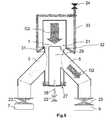
- the inert gas injection means 33 are oriented towards the center of the inlet 1 of the pipe, so as to create an annular jet, slightly conical, as shown in FIGS. figures 6 and 7 .
- the figure 7 represents the orientation of the injection of the inert gas at the inlet 1 represented on the figure 4 .
- the gas injection means inert 33 of the peripheral portion 31 are activated (the inert gas injection means 35 of the inner part 29 remaining inactivated) so as to direct the second reactive gas G2 to the inner portion 29 of the central trunk 27 and consequently to the corresponding vacuum pump 9.
- the second inert gas injection means 35 of the inner portion 29 of the central trunk 27 are located in the axis of the inner portion 29 and at the end opposite the inlet 1 of the pipe and are oriented towards the input 1 as represented on the figure 5 .
- these gas injection means inert 35 are activated by the opening of a valve 22 (the inert gas injection means 33 of the peripheral portion 31 remaining inactivated by the closing of the valve 24) so as to prevent the reactive gas G1 from entering the internal part 29 and to force it to go in the evacuation route 3 linked to the peripheral portion 31 of the central trunk 27.
- an injected inert gas 21 thus constitutes a gaseous screen making it possible to block the entrance of the selected evacuation channel with respect to a reactive gas, and consequently to direct a reactive gas into the gas channel.
- evacuation dedicated thereto without the need for valves or other mechanical elements, the latter being able to be deteriorated by interaction with the reactive gases.
- the embodiments of the present invention thus make it possible to avoid the use of mechanical parts that can become blocked or clogged, thereby improving the service life of the pipe while reducing its maintenance.
- the change of orientation of the reactive gas from one evacuation route to another can be done more quickly compared to the solutions of the state of the art.
- the embodiments of the present invention allow a constant dilution of the reactive gas upstream of the pumping system, thus facilitating its treatment.
Landscapes
- Chemical & Material Sciences (AREA)
- General Chemical & Material Sciences (AREA)
- Chemical Kinetics & Catalysis (AREA)
- Engineering & Computer Science (AREA)
- Materials Engineering (AREA)
- Mechanical Engineering (AREA)
- Metallurgy (AREA)
- Organic Chemistry (AREA)
- Chemical Vapour Deposition (AREA)
Abstract
Description
La présente invention concerne l'évacuation des gaz d'un réacteur et plus particulièrement l'évacuation des résidus de gaz réactifs en sortie d'un réacteur chimique tel que le réacteur d'un équipement de dépôt de couches atomiques.The present invention relates to the evacuation of gases from a reactor and more particularly the evacuation of reactive gas residues at the outlet of a chemical reactor such as the reactor of an atomic layer deposition equipment.
Le fonctionnement habituel d'un équipement de dépôt en couche atomique selon l'état de la technique est décrit ci-après. Deux gaz réactifs G1 et G2 sont introduits séquentiellement dans un réacteur dans lequel se trouve un substrat (« wafer » en anglais) afin de permettre le dépôt d'une couche atomique sur le substrat. Une haute température est maintenue dans le réacteur par des éléments chauffants. Le résidu de gaz réactif (G1 ou G2) est évacué au travers d'une canalisation d'évacuation située en sortie de réacteur vers une pompe à vide.
Le problème avec une telle méthode est que les deux gaz réactifs G1 et G2 peuvent être mélangés au niveau de la pompe à vide. Un tel mélange peut produire des réactions chimiques conduisant à la formation de particules solides et de poudres dans la pompe à vide qui permet d'évacuer les gaz G1 et G2. Les particules solides et les poudres s'accumulant dans la pompe à vide peuvent conduire à une panne et/ou à une détérioration prématurée de la pompe à vide impactant par là même le coût de fabrication global des substrats.
Afin de surmonter ce problème, les solutions de l'état de la technique correspondent à l'utilisation de deux pompes à vide distinctes, chacune étant dédiée à un gaz réactif. La transmission vers l'une ou l'autre des pompes à vide étant réalisée par un système de vannes mécaniques à l'entrée de la canalisation d'évacuation dirigeant le gaz réactif vers l'une ou l'autre des voies d'évacuation de la canalisation auxquelles sont connectées les pompes à vide.
Néanmoins, avec de telles solutions, le mélange des gaz réactifs peut se produire au niveau des vannes mécaniques, entraînant le dépôt d'une couche de sous-produit au niveau des vannes ce qui peut perturber leur fonctionnement et conduire à une panne.
Le but de l'invention est donc de proposer un dispositif permettant d'éviter un mélange des gaz réactifs au niveau des éléments mécaniques en mouvement afin d'empêcher la formation de sous-produits pouvant conduire à une panne de fonctionnement et permettant également une orientation du gaz réactif d'une voie d'évacuation vers une autre voie d'évacuation de manière plus rapide et donc plus adaptée aux procédés pulsés tels que le procédé de dépôt en couches atomiques.The usual operation of atomic layer deposition equipment according to the state of the art is described below. Two reactive gases G1 and G2 are introduced sequentially into a reactor in which there is a substrate ("wafer" in English) to allow the deposition of an atomic layer on the substrate. High temperature is maintained in the reactor by heating elements. The reactive gas residue (G1 or G2) is discharged through an evacuation pipe at the outlet of the reactor to a vacuum pump.
The problem with such a method is that both reactive gases G1 and G2 can be mixed at the vacuum pump. Such a mixture can produce chemical reactions leading to the formation of solid particles and powders in the vacuum pump which allows the gases G1 and G2 to be evacuated. Solid particles and powders accumulating in the vacuum pump can lead to premature failure and / or deterioration of the vacuum pump thereby impacting the overall manufacturing cost of the substrates.
In order to overcome this problem, the solutions of the state of the art correspond to the use of two separate vacuum pumps, each being dedicated to a reactive gas. The transmission to one or the other of the vacuum pumps being carried out by a system of mechanical valves at the entrance of the an evacuation pipe directing the reactive gas towards one or the other of the evacuation routes of the pipe to which the vacuum pumps are connected.
Nevertheless, with such solutions, the mixing of the reactive gases can occur at the mechanical valves, resulting in the deposition of a by-product layer at the valves which can disrupt their operation and lead to failure.
The object of the invention is therefore to provide a device for preventing a mixing of the reactive gases at the moving mechanical elements in order to prevent the formation of by-products that can lead to a malfunction and also allowing an orientation. reactive gas from one evacuation route to another evacuation route in a more rapid manner and thus more suitable for pulsed processes such as the atomic layer deposition process.
Ainsi, le dispositif selon la présente invention est une canalisation d'évacuation de gaz comprenant une première voie d'évacuation et au moins une deuxième voie d'évacuation destinées à être connectées respectivement à une première pompe à vide et à au moins une deuxième pompe à vide d'une part et à une sortie d'un réacteur d'autre part dans laquelle la première et au moins la deuxième voie d'évacuation comprennent des premiers et au moins des deuxièmes moyens d'injection d'un gaz inerte dont la direction de l'injection est respectivement orientée à l'opposé du sens d'aspiration des pompes à vide.
On entend par gaz inerte un gaz inerte unique ou un mélange de gaz inertes. Le gaz inerte peut être par exemple de l'azote N2, de l'Argon Ar et/ou de l'hélium He.
Selon un autre aspect de la présente invention, la canalisation comprend un tronc central mettant en communication d'une part la sortie du réacteur et d'autre part la première et au moins la deuxième voies d'évacuation, la première et au moins la deuxième voies d'évacuation ayant des conductances du même ordre de grandeur.
Selon un aspect additionnel de la présente invention, les voies d'évacuation sont au nombre de deux et le tronc central comprend d'une part une partie interne en communication avec la première voie d'évacuation et d'autre part une partie périphérique séparée de la partie interne par une paroi, en communication avec la deuxième voie d'évacuation.
Selon un aspect supplémentaire de la présente invention, les conductances respectives de la partie interne et de la partie périphérique du tronc central sont du même ordre de grandeur.
Selon un autre aspect de la présente invention, les premiers moyens d'injection d'un gaz inerte sont situés dans l'axe de la partie interne du tronc central et sont orientés vers la sortie du réacteur, tandis que les deuxièmes moyens d'injection d'un gaz inerte sont situés sur le pourtour de la partie périphérique du tronc central, et sont orientés sensiblement vers le centre de la section du tronc central.
La présente invention a également pour objet un procédé d'évacuation d'un premier et d'au moins un deuxième gaz réactifs issus d'un réacteur par une canalisation d'évacuation, le premier et au moins le deuxième gaz réactifs étant évacués de manière séquentielle par une première et au moins une deuxième voies d'évacuation connectées à une première et à au moins une deuxième pompes à vide, dans lequel l'orientation de la circulation d'un gaz réactif vers l'une des voies d'évacuation est contrôlée par l'injection d'un gaz inerte sensiblement en sens opposé au sens d'aspiration des pompes à vide respectives.
Selon un autre aspect de la présente invention, l'injection de gaz inerte est réalisée à l'entrée d'une au moins des première et deuxième voies d'évacuation.
Selon un aspect additionnel de la présente invention, les premier et au moins deuxième gaz réactifs issus du réacteur sont reçus séquentiellement, et les première et au moins deuxième pompes à vide sont dédiées respectivement au premier et au moins deuxième gaz réactif de sorte qu'un gaz inerte est injecté au niveau de la première voie d'évacuation lorsque le gaz réactif à évacuer est destiné à la deuxième pompe à vide et qu'un gaz inerte est injecté au niveau de la deuxième voie d'évacuation lorsque le gaz réactif à évacuer est destiné à la première pompe à vide.
Selon un aspect supplémentaire de la présente invention, les premier et au moins deuxième gaz réactifs issus du réacteur sont reçus alternativement, de sorte que l'injection d'un gaz inerte au niveau des voies d'évacuation est aussi réalisée de manière alternative.
Selon un autre aspect de la présente invention, la quantité de gaz inerte injectée est la même pour les deux séquences de l'alternance et est calculée pour obtenir une concentration de 20% de gaz réactif dans le mélange gazeux au niveau de la pompe à vide, le mélange gazeux au niveau de la pompe à vide étant composé de gaz réactif et de gaz inerte injecté.
D'autres caractéristiques et avantages de l'invention apparaîtront dans la description qui va maintenant en être faite, en référence aux dessins annexés qui en représentent, à titre indicatif mais non limitatif, un mode de réalisation possible.
Sur ces dessins:
- la
figure 1 représente un schéma d'un premier mode de réalisation d'une canalisation d'évacuation selon la présente invention; - la
figure 2 représente un schéma du premier mode de réalisation d'une canalisation d'évacuation selon la présente invention lorsque les premiers moyens d'injection de gaz inerte sont activés; - la
figure 3 représente un schéma d'un deuxième mode de réalisation d'une canalisation d'évacuation selon la présente invention; - la
figure 4 représente un schéma d'une vue en coupe transversale de la canalisation au niveau de l'entrée de la canalisation pour le deuxième mode de réalisation de la présente invention; - la
figure 5 représente un schéma d'une première étape de fonctionnement du deuxième mode de réalisation d'une canalisation d'évacuation selon la présente invention lorsque les premiers moyens d'injection de gaz inerte sont activés; - la
figure 6 représente un schéma d'une deuxième étape de fonctionnement du deuxième mode de réalisation d'une canalisation d'évacuation selon la présente invention lorsque les deuxièmes moyens d'injection de gaz inerte sont activés; - la
figure 7 représente un schéma d'une vue en coupe transversale de la canalisation au niveau de l'entrée de la canalisation et la direction du gaz inerte lorsque les deuxièmes moyens d'injection sont activés.
By inert gas is meant a single inert gas or a mixture of inert gases. The inert gas may be, for example, N 2 nitrogen, Argon Ar and / or Helium He.
According to another aspect of the present invention, the pipe comprises a central trunk connecting on the one hand the outlet of the reactor and on the other hand the first and at least the second lanes. the first and at least the second escape routes having conductances of the same order of magnitude.
According to an additional aspect of the present invention, the evacuation routes are two in number and the central trunk comprises on the one hand an internal part in communication with the first escape route and on the other hand a peripheral part separated from the inner part by a wall, in communication with the second escape route.
According to a further aspect of the present invention, the respective conductances of the inner part and the peripheral part of the central trunk are of the same order of magnitude.
According to another aspect of the present invention, the first means for injecting an inert gas are located in the axis of the internal part of the central trunk and are oriented towards the outlet of the reactor, while the second injection means an inert gas are located around the perimeter of the central trunk, and are oriented substantially towards the center of the section of the central trunk.
The present invention also relates to a method of evacuating a first and at least a second reactive gas from a reactor through an evacuation pipe, the first and at least the second reactant gas being evacuated sequentially by a first and at least a second evacuation routes connected to a first and at least a second vacuum pumps, wherein the orientation of the circulation of a reactive gas towards one of the escape routes is controlled by the injection of an inert gas substantially in opposite direction to the suction direction of the respective vacuum pumps.
According to another aspect of the present invention, the injection of inert gas is performed at the entrance of at least one of the first and second escape routes.
According to an additional aspect of the present invention, the first and at least second reagent gases from the reactor are received sequentially, and the first and at least second vacuum pumps are respectively dedicated to the first and at least second reactive gases so that an inert gas is injected at the first evacuation route when the reactive gas to be evacuated is destined for the second vacuum pump and an inert gas is injected at the second exhaust path when the reactive gas to be evacuated is for the first vacuum pump.
According to a further aspect of the present invention, the first and at least second reactive gases from the reactor are received alternately, so that the injection of an inert gas at the evacuation routes is also performed alternately.
According to another aspect of the present invention, the amount of inert gas injected is the same for both sequences of the alternation and is calculated to obtain a concentration of 20% of reactive gas in the gas mixture at the vacuum pump. , the gas mixture at the vacuum pump being composed of reactive gas and injected inert gas.
Other features and advantages of the invention will appear in the description which will now be made, with reference to the accompanying drawings which represent, by way of indication but not limitation, a possible embodiment.
On these drawings:
- the
figure 1 represents a diagram of a first embodiment of an exhaust pipe according to the present invention; - the
figure 2 represents a diagram of the first embodiment of an exhaust pipe according to the present invention when the first inert gas injection means are activated; - the
figure 3 represents a diagram of a second embodiment of an exhaust pipe according to the present invention; - the
figure 4 shows a schematic of a cross-sectional view of the pipe at the inlet of the pipe for the second embodiment of the present invention; - the
figure 5 represents a diagram of a first operating step of the second embodiment of an exhaust pipe according to the present invention when the first inert gas injection means are activated; - the
figure 6 shows a diagram of a second operating step of the second embodiment of an exhaust pipe according to the present invention when the second inert gas injection means are activated; - the
figure 7 represents a diagram of a cross-sectional view of the pipe at the inlet of the pipe and the direction of the inert gas when the second injection means are activated.
Dans le cadre de la présente invention, le terme « conductance » d'une canalisation est le quotient du flux divisé par la différence de pression en amont et en aval de la canalisation et correspond à la facilité d'écoulement d'un fluide dans la canalisation.In the context of the present invention, the term "conductance" of a pipe is the quotient of the flow divided by the pressure difference upstream and downstream of the pipe and corresponds to the ease of flow of a fluid in the pipe. pipe.
Les modes de réalisation de la présente invention concernent l'utilisation d'un gaz inerte au niveau d'une canalisation d'évacuation de gaz réactif issu d'un réacteur, par exemple un réacteur de dépôt de couches atomiques, comprenant au moins deux voies d'évacuation afin d'orienter le gaz réactif à évacuer vers l'une des voies d'évacuation.
La
La canalisation comprend une entrée 1 destinée à être connectée à la sortie d'un réacteur afin de recevoir les résidus de deux gaz réactifs, ou de deux mélanges différents de gaz réactifs, issus du réacteur, deux voies d'évacuation 3 et 5 reliées chacune à une pompe à vide 7 et 9 et un tronc central 11 reliant l'entrée 1 de la canalisation aux deux voies d'évacuation 3 et 5. Les voies d'évacuation étant réalisées de manière à obtenir une conductance, par exemple en ayant des dimensions similaires et une capacité de pompage similaire ayant le même ordre de grandeur.
De plus, chaque voie d'évacuation comprend respectivement des premiers et deuxièmes moyens d'injection d'un gaz inerte 13 et 15. Ces moyens d'injections 13 et 15 peuvent par exemple comprendre une première 17 et une deuxième 18 vanne pour laisser passer ou bloquer le gaz inerte et une première 19 et une deuxième 20 buse d'injection pour diffuser le gaz inerte dans la direction choisie, en sens opposé à la direction de pompage (c'est à dire à contre-sens du sens de propagation du gaz réactif dans la voie d'évacuation).The embodiments of the present invention relate to the use of an inert gas at a reactant gas evacuation pipe from a reactor, for example an atomic layer deposition reactor, comprising at least two channels discharge pipe to direct the reactive gas to evacuate towards one of the evacuation routes.
The
The pipe comprises an
In addition, each evacuation route comprises respectively first and second means for injecting an
Ainsi, l'injection de gaz inerte 21 à contre-sens dans l'une des voies d'évacuation permet de diriger le gaz réactif vers l'autre voie d'évacuation comme représenté sur la
Lorsque le gaz G1 est reçu à l'entrée 1 de la canalisation, les deuxièmes moyens d'injection 15 d'un gaz inerte 21 de la deuxième voie d'évacuation 5 sont activés, alors que les moyens d'injection 13 d'un gaz inerte 21 de la première voie d'évacuation 3 sont désactivés. Le gaz G1 est ainsi dirigé vers la première pompe à vide 7 dédiée au pompage du gaz G1.
En pratique, les deux gaz G1 et G2 sont généralement injectés alternativement dans le réacteur de sorte que l'activation des premiers et deuxièmes moyens d'injection de gaz inerte 13 et 15 est également réalisée de façon alternative en fonction du gaz réactif G1 ou G2 présent dans le réacteur.
D'autre part, la quantité de gaz inerte 21 injectée peut être réglée en fonction de la quantité de gaz réactif G1 ou G2 à évacuer et de la concentration de gaz réactif G1 ou G2 désirée au niveau de la pompe à vide 7 ou 9. Avantageusement, la quantité de gaz inerte 21 est la même pour les deux séquences d'injection de l'alternance de manière à ne pas modifier la pression à l'intérieur du réacteur et de la canalisation. La quantité de gaz inerte injectée est calculée pour obtenir une concentration de 20% de gaz réactif G1 ou G2 dans le mélange gazeux au niveau de la pompe à vide, le mélange gazeux au niveau de la pompe à vide étant composé de gaz réactif G1, G2 et de gaz inerte injecté 21. On considère que la concentration en sortie du réacteur du gaz réactif G1 ou G2 est de 100%.
Si cela est nécessaire, en fonction du système de pompage, cette concentration de gaz réactif G1 ou G2 au niveau de la pompe à vide peut être réduite à 1%.
De plus, selon un mode de réalisation, les premiers et deuxièmes moyens d'injection 13 et 15 ne bloquent pas totalement le passage du gaz inerte 21 lorsqu'ils sont inactifs, mais sont mis dans un mode veille dans lequel une faible quantité de gaz inerte 21 continue à être injectée pour empêcher la formation de dépôt sur les buses d'injection 19 et 20 du gaz inerte, protégeant ainsi les buses d'injection 19 et 20.
Par ailleurs, des vannes 23 et 25 sont situées à la sortie des voies d'évacuation 3 et 5 et à l'entrée des pompes à vide 7 et 9. Ces vannes 23 et 25 sont des vannes automatiques qui restent ouvertes en permanence en fonctionnement normal, et sont fermées en cas de panne de la pompe à vide correspondante afin d'isoler la pompe à vide défaillante de la canalisation.
De plus, seules deux voies d'évacuation sont représentées sur les
When the gas G1 is received at the
In practice, the two gases G1 and G2 are generally injected alternately into the reactor so that the activation of the first and second second inert gas injection means 13 and 15 is also performed alternately depending on the reactive gas G1 or G2 present in the reactor.
On the other hand, the quantity of
If necessary, depending on the pumping system, this concentration of reactive gas G1 or G2 at the vacuum pump can be reduced to 1%.
In addition, according to one embodiment, the first and second injection means 13 and 15 do not completely block the passage of the
Furthermore,
In addition, only two escape routes are represented on the
La
La
Néanmoins, la présente invention peut également s'appliquer à des sections de forme différente comme par exemple des sections ovales, voir rectangulaires ou carrées.
Comme pour le mode de réalisation précédent, des premiers et deuxièmes moyens d'injection de gaz inerte 33 et 35 sont utilisés afin d'orienter les résidus de gaz réactifs G1 ou G2 issus du réacteur vers l'une ou l'autre des voies d'évacuation pour être transmis à la pompe à vide dédiée, 7 ou 9.The
Nevertheless, the present invention can also be applied to sections of different shape such as oval, rectangular or square sections.
As for the previous embodiment, first and second inert gas injection means 33 and 35 are used in order to orient the reactive gas residues G1 or G2 from the reactor to one or the other of the reaction channels. evacuation to be transmitted to the dedicated vacuum pump, 7 or 9.
Les premiers moyens d'injection de gaz inerte 33 de la partie périphérique 31 sont régulièrement répartis sur le pourtour de la partie périphérique 31 (par exemple en utilisant un ensemble de buses d'injection 32 reliées à une arrivée de gaz inerte contrôlée par une vanne 24) au niveau de l'entrée 1 de la canalisation. Les moyens d'injection de gaz inerte 33 sont orientés vers le centre de l'entrée 1 de la canalisation, de manière à créer un jet annulaire, légèrement conique, comme représenté sur les
Ainsi, lorsque le deuxième gaz réactif G2 destiné à la pompe à vide 9 connectée à la deuxième voie d'évacuation 5 reliée à la partie interne 29 du tronc central 27 est reçu en entrée 1 de la canalisation, les moyens d'injection de gaz inerte 33 de la partie périphérique 31 sont activés (les moyens d'injection de gaz inerte 35 de la partie interne 29 restant inactivés) de manière à diriger le deuxième gaz réactif G2 vers la partie interne 29 du tronc central 27 et par conséquence vers la pompe à vide 9 correspondante.
Les deuxièmes moyens d'injection de gaz inerte 35 de la partie interne 29 du tronc central 27 sont situés dans l'axe de la partie interne 29 et à l'extrémité opposée à l'entrée 1 de la canalisation et sont orientés vers l'entrée 1 comme représenté sur la
Ainsi, lorsque le premier gaz réactif G1 destiné à la pompe à vide 7 connectée à la première voie d'évacuation 3 reliée à la partie périphérique 31 du tronc central 27 est reçu en entrée 1 de la canalisation, ces moyens d'injection de gaz inerte 35 sont activés par l'ouverture d'une vanne 22 (les moyens d'injection de gaz inerte 33 de la partie périphérique 31 restant inactivés par la fermeture de la vanne 24) de manière à empêcher le gaz réactif G1 de rentrer dans la partie interne 29 et à le forcer à aller dans la voie d'évacuation 3 liée à la partie périphérique 31 du tronc central 27.The first inert gas injection means 33 of the
Thus, when the second reactive gas G2 for the
The second inert gas injection means 35 of the
Thus, when the first reactive gas G1 for the
L'utilisation d'un gaz inerte 21 injecté constitue donc un écran gazeux permettant de bloquer l'entrée de la voie d'évacuation sélectionnée vis à vis d'un gaz réactif, et par conséquence d'orienter un gaz réactif dans la voie d'évacuation qui lui est dédiée sans avoir besoin de vannes ou autres éléments mécaniques, ces derniers pouvant être détériorés par interaction avec les gaz réactifs. Les modes de réalisation de la présente invention permettent donc d'éviter l'utilisation de parties mécaniques pouvant se bloquer ou se boucher, améliorant ainsi la durée de vie de la canalisation tout en réduisant sa maintenance. De plus, le changement d'orientation du gaz réactif d'une voie d'évacuation vers une autre peut se faire de manière plus rapide par rapport aux solutions de l'état de la technique. Enfin, les modes de réalisation de la présente invention permettent une dilution constante du gaz réactif en amont du système de pompage, facilitant ainsi son traitement.The use of an injected
Claims (10)
Priority Applications (1)
| Application Number | Priority Date | Filing Date | Title |
|---|---|---|---|
| EP11187034.1A EP2586890A1 (en) | 2011-10-28 | 2011-10-28 | Pipe for evacuating gas and related evacuation method |
Applications Claiming Priority (1)
| Application Number | Priority Date | Filing Date | Title |
|---|---|---|---|
| EP11187034.1A EP2586890A1 (en) | 2011-10-28 | 2011-10-28 | Pipe for evacuating gas and related evacuation method |
Publications (1)
| Publication Number | Publication Date |
|---|---|
| EP2586890A1 true EP2586890A1 (en) | 2013-05-01 |
Family
ID=45023592
Family Applications (1)
| Application Number | Title | Priority Date | Filing Date |
|---|---|---|---|
| EP11187034.1A Withdrawn EP2586890A1 (en) | 2011-10-28 | 2011-10-28 | Pipe for evacuating gas and related evacuation method |
Country Status (1)
| Country | Link |
|---|---|
| EP (1) | EP2586890A1 (en) |
Cited By (1)
| Publication number | Priority date | Publication date | Assignee | Title |
|---|---|---|---|---|
| CN111670265A (en) * | 2018-01-31 | 2020-09-15 | 朗姆研究公司 | Manifold valve for multiple precursors |
Citations (3)
| Publication number | Priority date | Publication date | Assignee | Title |
|---|---|---|---|---|
| US20020023588A1 (en) * | 1999-06-03 | 2002-02-28 | Mitsubishi Denki Kabushiki Kaisha | Chemical vapor deposition apparatus and a method of manufacturing a semiconductor device |
| US20040250765A1 (en) * | 2002-10-03 | 2004-12-16 | Tokyo Electron Limited | Processing apparatus |
| US20100012292A1 (en) * | 2007-03-31 | 2010-01-21 | Tokyo Electron Limited | Trap apparatus, exhaust system and processing system using same |
-
2011
- 2011-10-28 EP EP11187034.1A patent/EP2586890A1/en not_active Withdrawn
Patent Citations (3)
| Publication number | Priority date | Publication date | Assignee | Title |
|---|---|---|---|---|
| US20020023588A1 (en) * | 1999-06-03 | 2002-02-28 | Mitsubishi Denki Kabushiki Kaisha | Chemical vapor deposition apparatus and a method of manufacturing a semiconductor device |
| US20040250765A1 (en) * | 2002-10-03 | 2004-12-16 | Tokyo Electron Limited | Processing apparatus |
| US20100012292A1 (en) * | 2007-03-31 | 2010-01-21 | Tokyo Electron Limited | Trap apparatus, exhaust system and processing system using same |
Cited By (3)
| Publication number | Priority date | Publication date | Assignee | Title |
|---|---|---|---|---|
| CN111670265A (en) * | 2018-01-31 | 2020-09-15 | 朗姆研究公司 | Manifold valve for multiple precursors |
| US11427908B2 (en) | 2018-01-31 | 2022-08-30 | Lam Research Corporation | Manifold valve for multiple precursors |
| US11859282B2 (en) | 2018-01-31 | 2024-01-02 | Lam Research Corporation | Manifold valve for controlling multiple gases |
Similar Documents
| Publication | Publication Date | Title |
|---|---|---|
| FR2965888A1 (en) | GAS DRAIN PIPING AND ASSOCIATED DRAINAGE METHOD | |
| CN112051012B (en) | Gas phase reactor system comprising a gas detector | |
| EP1190285B1 (en) | Method and device for conditioning atmosphere in a process chamber | |
| US8372201B2 (en) | High temperature ALD inlet manifold | |
| EP2875240B1 (en) | Method and device for pumping of a process chamber | |
| EP0759320B1 (en) | Apparatus for separating gas by adsorption | |
| EP2586890A1 (en) | Pipe for evacuating gas and related evacuation method | |
| FR2998634A1 (en) | SPHERICAL SHUTTER VALVE, IN PARTICULAR FOR GAS TURBINE | |
| JP7151420B2 (en) | Gas supply device and gas supply method | |
| WO2020164876A1 (en) | Sniffer probe and leak detector | |
| KR102694942B1 (en) | Gas supply apparatus | |
| EP0716296A1 (en) | Leak detector | |
| KR20040020821A (en) | Thin-film deposition apparatus and method for rapidly switching supply of source gases | |
| TWI811992B (en) | Gas supply device, vacuum processing device and gas supply method | |
| KR20230131558A (en) | Gas supply apparatus | |
| FR2932059A1 (en) | PLASMA TREATMENT SYSTEM OF FLUID OR MIXTURE OF FLUIDS | |
| WO2021014105A1 (en) | Reactor for depositing material on a surface of a substrate arranged inside the reactor, and method for depositing the material on a substrate while protecting the reactor wall | |
| JP2635119B2 (en) | Vacuum equipment | |
| JPH11117072A (en) | Method for carrying substrate in/out of chamber | |
| KR20040104090A (en) | Method of preventing process badness by pump trip in Pump equipment | |
| KR20040029196A (en) | Exhaust system of chamber having valves for semiconductor and thinfilmtransistor liquid crystal display manufacture |
Legal Events
| Date | Code | Title | Description |
|---|---|---|---|
| PUAI | Public reference made under article 153(3) epc to a published international application that has entered the european phase |
Free format text: ORIGINAL CODE: 0009012 |
|
| AK | Designated contracting states |
Kind code of ref document: A1 Designated state(s): AL AT BE BG CH CY CZ DE DK EE ES FI FR GB GR HR HU IE IS IT LI LT LU LV MC MK MT NL NO PL PT RO RS SE SI SK SM TR |
|
| AX | Request for extension of the european patent |
Extension state: BA ME |
|
| STAA | Information on the status of an ep patent application or granted ep patent |
Free format text: STATUS: THE APPLICATION IS DEEMED TO BE WITHDRAWN |
|
| 18D | Application deemed to be withdrawn |
Effective date: 20131105 |