EP2586729A1 - Anchor chain guide mechanism for ladle conveyance - Google Patents
Anchor chain guide mechanism for ladle conveyance Download PDFInfo
- Publication number
- EP2586729A1 EP2586729A1 EP10853696.2A EP10853696A EP2586729A1 EP 2586729 A1 EP2586729 A1 EP 2586729A1 EP 10853696 A EP10853696 A EP 10853696A EP 2586729 A1 EP2586729 A1 EP 2586729A1
- Authority
- EP
- European Patent Office
- Prior art keywords
- anchor chain
- guide
- chain
- motive power
- anchor
- Prior art date
- Legal status (The legal status is an assumption and is not a legal conclusion. Google has not performed a legal analysis and makes no representation as to the accuracy of the status listed.)
- Withdrawn
Links
- 230000005540 biological transmission Effects 0.000 claims abstract description 17
- 239000005997 Calcium carbide Substances 0.000 claims description 8
- CLZWAWBPWVRRGI-UHFFFAOYSA-N tert-butyl 2-[2-[2-[2-[bis[2-[(2-methylpropan-2-yl)oxy]-2-oxoethyl]amino]-5-bromophenoxy]ethoxy]-4-methyl-n-[2-[(2-methylpropan-2-yl)oxy]-2-oxoethyl]anilino]acetate Chemical compound CC1=CC=C(N(CC(=O)OC(C)(C)C)CC(=O)OC(C)(C)C)C(OCCOC=2C(=CC=C(Br)C=2)N(CC(=O)OC(C)(C)C)CC(=O)OC(C)(C)C)=C1 CLZWAWBPWVRRGI-UHFFFAOYSA-N 0.000 claims description 8
- 238000000034 method Methods 0.000 description 3
- 238000006073 displacement reaction Methods 0.000 description 2
- 238000007665 sagging Methods 0.000 description 2
- 230000003319 supportive effect Effects 0.000 description 2
- 235000008733 Citrus aurantifolia Nutrition 0.000 description 1
- 229910000831 Steel Inorganic materials 0.000 description 1
- 235000011941 Tilia x europaea Nutrition 0.000 description 1
- 239000000571 coke Substances 0.000 description 1
- 238000001816 cooling Methods 0.000 description 1
- 230000008878 coupling Effects 0.000 description 1
- 238000010168 coupling process Methods 0.000 description 1
- 238000005859 coupling reaction Methods 0.000 description 1
- 230000007547 defect Effects 0.000 description 1
- 239000012530 fluid Substances 0.000 description 1
- 238000010438 heat treatment Methods 0.000 description 1
- 239000004571 lime Substances 0.000 description 1
- 238000004519 manufacturing process Methods 0.000 description 1
- 239000000203 mixture Substances 0.000 description 1
- 239000010959 steel Substances 0.000 description 1
- 238000003466 welding Methods 0.000 description 1
Images


Classifications
-
- B—PERFORMING OPERATIONS; TRANSPORTING
- B65—CONVEYING; PACKING; STORING; HANDLING THIN OR FILAMENTARY MATERIAL
- B65G—TRANSPORT OR STORAGE DEVICES, e.g. CONVEYORS FOR LOADING OR TIPPING, SHOP CONVEYOR SYSTEMS OR PNEUMATIC TUBE CONVEYORS
- B65G21/00—Supporting or protective framework or housings for endless load-carriers or traction elements of belt or chain conveyors
- B65G21/20—Means incorporated in, or attached to, framework or housings for guiding load-carriers, traction elements or loads supported on moving surfaces
- B65G21/22—Rails or the like engaging sliding elements or rollers attached to load-carriers or traction elements
-
- B—PERFORMING OPERATIONS; TRANSPORTING
- B65—CONVEYING; PACKING; STORING; HANDLING THIN OR FILAMENTARY MATERIAL
- B65G—TRANSPORT OR STORAGE DEVICES, e.g. CONVEYORS FOR LOADING OR TIPPING, SHOP CONVEYOR SYSTEMS OR PNEUMATIC TUBE CONVEYORS
- B65G23/00—Driving gear for endless conveyors; Belt- or chain-tensioning arrangements
- B65G23/02—Belt- or chain-engaging elements
- B65G23/14—Endless driving elements extending parallel to belt or chain
- B65G23/16—Endless driving elements extending parallel to belt or chain with dogs engaging abutments on belts or chains
-
- B—PERFORMING OPERATIONS; TRANSPORTING
- B65—CONVEYING; PACKING; STORING; HANDLING THIN OR FILAMENTARY MATERIAL
- B65G—TRANSPORT OR STORAGE DEVICES, e.g. CONVEYORS FOR LOADING OR TIPPING, SHOP CONVEYOR SYSTEMS OR PNEUMATIC TUBE CONVEYORS
- B65G23/00—Driving gear for endless conveyors; Belt- or chain-tensioning arrangements
- B65G23/38—Driving gear for endless conveyors; Belt- or chain-tensioning arrangements for effecting intermittent movement of belts or chains
-
- C—CHEMISTRY; METALLURGY
- C21—METALLURGY OF IRON
- C21C—PROCESSING OF PIG-IRON, e.g. REFINING, MANUFACTURE OF WROUGHT-IRON OR STEEL; TREATMENT IN MOLTEN STATE OF FERROUS ALLOYS
- C21C5/00—Manufacture of carbon-steel, e.g. plain mild steel, medium carbon steel or cast steel or stainless steel
- C21C5/52—Manufacture of steel in electric furnaces
- C21C5/5294—General arrangement or layout of the electric melt shop
-
- F—MECHANICAL ENGINEERING; LIGHTING; HEATING; WEAPONS; BLASTING
- F27—FURNACES; KILNS; OVENS; RETORTS
- F27D—DETAILS OR ACCESSORIES OF FURNACES, KILNS, OVENS OR RETORTS, IN SO FAR AS THEY ARE OF KINDS OCCURRING IN MORE THAN ONE KIND OF FURNACE
- F27D3/00—Charging; Discharging; Manipulation of charge
- F27D3/12—Travelling or movable supports or containers for the charge
-
- Y—GENERAL TAGGING OF NEW TECHNOLOGICAL DEVELOPMENTS; GENERAL TAGGING OF CROSS-SECTIONAL TECHNOLOGIES SPANNING OVER SEVERAL SECTIONS OF THE IPC; TECHNICAL SUBJECTS COVERED BY FORMER USPC CROSS-REFERENCE ART COLLECTIONS [XRACs] AND DIGESTS
- Y02—TECHNOLOGIES OR APPLICATIONS FOR MITIGATION OR ADAPTATION AGAINST CLIMATE CHANGE
- Y02P—CLIMATE CHANGE MITIGATION TECHNOLOGIES IN THE PRODUCTION OR PROCESSING OF GOODS
- Y02P10/00—Technologies related to metal processing
- Y02P10/20—Recycling
Definitions
- the present invention relates to a guide mechanism of an anchor chain for conveying ladles, and more particular to a guide mechanism for introducing and guiding an anchor chain for conveying ladles, which receive a product (calcium carbide) from a calcium carbide producing furnace, into a motive power transmission region along a loop track.
- a product calcium carbide
- Calcium carbide (hereinafter also referred to as merely “carbide”) can be produced by heating a mixture of lime and coke to 2000 °C or more in an electric furnace.
- Product as molten in the furnace is sequentially received through tap outlets by a plurality of ladles. Then, those ladles are conveyed to a product processing region away from the furnace. In the product processing region, the products are unloaded from the ladles such as by using a ceiling crane, and cooling, crushing and other processes are carried out on the products.
- the ladles as emptied in the product processing region are conveyed to the tap outlets of the furnace to receive the products again.
- the weight of one ladle is approximately 1400 kg as an example.
- the weight of the molten carbide that is received by one ladle at one time is approximately 700 kg as an example. In a large furnace, it is needed to move approximately 100 ladles at the same time.
- a method is generally used in which many bogies on which the ladles are loaded are connected to an anchor chain which is disposed along a track, and the anchor chain is moved along the track by driving apparatuses. Examples of such an anchor chain method are disclosed in JP,S51-57487,A , JP,H04-235808,A , etc.
- a driving apparatus transmits an output of a motive power source to a conveyer chain through a decelerator and the like, and then to the anchor chain by sequentially engaging multi-engagement parts provided on the conveyer chain at predetermined intervals with the anchor chain as the conveyer chain is revolving. Thereby, the motive power is transmitted to the anchor chain.
- the weight of a unit ring constructing the anchor chain is approximately 4 kg as an example, and the weight of the entire anchor chain comes to approximately 8200 kg as an example.
- many ladles, bogies, etc. are connected to the anchor chain. Therefore, there is a case that a heavy-weighted anchor chain is twisted or sagged in a region where the motive power is transmitted from the driving apparatuses to the anchor chain. In this case, there is a problem that the motive power is not efficiently transmitted to the anchor chain. Further, when a positional displacement of the conveyer chain in the driving apparatus arises, a defect in the engagement with the anchor chain occurs, leading to a drop in motive power transmission efficiency to the anchor chain.
- a circular furnace with three tap outlets at 120 degree intervals in the circumferential direction is mainly used to increase efficiency in taking out the products.
- a sharply curved portion of the track is formed to pass the track through the three tap outlets. Slacks and the like of the anchor chain at the sharply curved portion would be a cause of twists and the like of the anchor chain in the motive power transmission region.
- an object of the present invention is to provide a guide mechanism of an anchor chain for conveying ladles, which can prevent an anchor chain from being twisted or sagged and a conveyer chain from being displaced in a motive power transmission region, and can transmit motive power to the anchor chain reliably and efficiently.
- a guide mechanism of an anchor chain for conveying ladles comprising: an anchor chain which is placed along a loop track in order to convey ladles, which receive a product from a calcium carbide producing furnace, along the track, the anchor chain arranged along being constituted by a plurality of longitudinal unit rings and a plurality of lateral unit rings alternately connected to each other; a conveyer chain which can revolve under the anchor chain to transmit motive power from a motive power source to the anchor chain to move the anchor chain along the track, the conveyer chain including a plurality of engagement parts which can be engaged with the anchor chain at predetermined intervals; a linear anchor chain guide which is provided in a motive power transmission region where the motive power is transmitted from the conveyer chain to the anchor chain, the linear anchor chain guide being along the longitudinal direction of the anchor chain; and a stopper which is fixed to an upper end of each of the longitudinal unit rings, wherein the anchor chain guide comprises a pair of left and right (the direction
- the linear anchor chain guide is provided in the motive power transmission region where the motive power is transmitted from the conveyer chain to the anchor chain, and the anchor chain is introduced and guided to the anchor chain guide.
- the guide side parts in the left and right guide half members constituting the anchor chain guide can limit a leftward or rightward movement of the anchor chain.
- the guide upper parts can limit an upward movement of the anchor chain.
- the stopper placed at the upper end of each vertical unit ring of the anchor chain cannot pass downwardly through the clearance set between the guide upper parts of the left and right guide half members. Therefore, a downward movement of the anchor chain can be limited.
- the anchor chain guide is open downwardly, and through this lower opening, the engagement parts of the conveyer chain are sequentially engaged with the anchor chain to push the anchor chain in the traveling direction.
- the guide mechanism includes a conveyer chain guide for positioning the conveyer chain with respect to the anchor chain.
- the conveyer chain guide can prevent the conveyer chain from floating or being detached and fix the position in which the engagement parts of the conveyer chain are engaged with the anchor chain.
- the anchor chain in the motive power transmission region, the anchor chain is restricted in the right and left direction and the up and down direction, twisting or sagging in the anchor chain can be prevented.
- the motive power can be transmitted from the conveyer chain to the anchor chain reliably and efficiently.
- a positional displacement of the conveyer chain can be prevented.
- the transmission of the motive power from the conveyer chain to the anchor chain becomes more reliable.
- Fig. 1 is an explanatory plane view schematically showing an track 4 etc. for conveying ladles 3 which receive molten products from tap outlets 2a, 2b and 2c of a calcium carbide producing furnace 1.
- the track 4 is laid in a loop form between the furnace 1 and a product processing region 5 away from the furnace 1.
- the track 4 includes a sharply curved portion 4' to pass the three tap outlets 2a, 2b and 2c which are provided at 120 degree intervals of the furnace 1 having a circular horizontal section.
- the anchor chain 10 receives motive power from two anchor chain driving apparatuses 20 as an example installed for the track 4 to move on the track 4 in the clockwise direction.
- the anchor chain driving apparatus 20 includes a conveyer chain 21 (see Fig. 2 etc.) for transmitting the motive power from a motive power source (motor) (not shown) to the anchor chain 10.
- a motive power source (motor) (not shown)
- an output of the motive power source is transmitted to the conveyer chain 21 through an electromagnetic clutch, a fluid coupling, a decelerator, a one-way clutch, a driving roller chain and the like,.
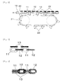
- Fig. 2 is an explanatory side view schematically showing a motive power transmission region in which the motive power is transmitted from the conveyer chain 21 of the anchor chain driving apparatus 20 to the anchor chain 10.
- a conveyer chain guide 40 as will be described later is omitted for convenience.
- Figs. 3 and 4 are a partial side view and a partial top view of the anchor chain 10, respectively.
- the anchor chain 10 is configured such that many vertical unit rings (hereafter also referred to as merely “vertical rings”) 11 made of typical structural rolled steel (SS) and many horizontal unit rings (hereinafter also referred to as merely “horizontal rings”) 12 are alternately connected to each other.
- a rectangular plate-like downward stopper 13 made of SS is fixed to a top of each longitudinal ring 11 by welding.
- the conveyer chain 21 is arranged just under the anchor chain 10 in the motive power transmission region, in order to transmit the motive power to the anchor chain 10.
- a plurality of hooks 22 as engagement parts are provided at predetermined intervals in the longitudinal direction of the conveyer chain 21.
- Each of the hooks 22 can be inserted into a gap between adjacent two lateral rings 12 in the anchor chain 10.
- the hook 22 is branched into two tip parts to be inserted between adjacent lateral rings 12 so as to sandwich the longitudinal ring 11 between them.
- the reference numeral 30 in Fig. 2 indicates an anchor chain guide, which is provided in the motive power transmission region.
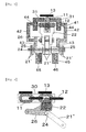
- Fig. 6 is an explanatory section view of the anchor chain guide 30.
- the anchor chain guide 30 is constituted by a pair of left and right guide half members 31, 31 made of the SS, which are supported by respective supportive components (not shown) and are linearly elongated in the traveling direction.
- the guide half members 31, 31 each have L-shaped section and are open downwardly. Through this lower opening in the guide 30, the above-mentioned engagement between the engagement parts 22 of the conveyer chain 21 and the anchor chain 10 is carried out.
- Each of those guide half members 31, 31 includes a guide side part 32 for limiting a leftward or rightward movement of the lateral rings 12 and a guide upper part 33 for limiting an upward movement of the lateral rings 12. Between the guide upper parts 33, 33 of the left and right guide half members 31, 31, a clearance 34 is set through which a portion of each of the longitudinal rings 11 above the lateral rings 12 can pass. The downward stopper 13 fixed to the upper end of the longitudinal ring 11 cannot pass through the clearance 34 downwardly. The anchor chain 10 is pulled into the motive power transmission region while being guided by the guide 30.
- the lateral ring 12 is passed to between the guide side parts 32, 32 of the guide half members 31, 31 and below the guide upper parts 33, 33, and an upper part of the longitudinal ring 11 is passed through the clearance 34.
- the downward stopper 13 of the longitudinal ring 11 is passed to above the guide upper parts 33, 33.
- Fig. 7 is a side view of the conveyer chain 21 similar to Fig. 2 , but it shows the conveyer chain guide 40 as omitted in Fig. 2 .
- the anchor chain 10 and the anchor chain guide 30 are omitted in Fig. 7 .
- Fig. 8 is an explanatory section view of the conveyer chain guide 40. In Fig. 8 , the anchor chain 10 and the guide 30 are also shown. Also referring to Fig.
- the conveyer chain 21 comprises left and right link chains 23, 23, each of which is constructed by a plurality of unit links 21' that are connected to each other in the longitudinal direction, a plurality of lateral shafts 24 which connect the left and right link chains 23, 23 while linking longitudinally adjacent unit links 21' , and two left and right rollers 25, 25 which are placed on the respective lateral shafts 24.
- a block plate 26 for connecting the hooks 22 is installed via the lateral shaft 24 at predetermined intervals in the longitudinal direction of the conveyer chain 21.
- the block plate 26 is provided every other unit link 21' .
- a region (unit region) between longitudinally adjacent two lateral shafts 24 comes to alternately the unit regions where the block plate 26 exists and the unit regions where the block plate 26 does not exist.
- the left and right inner unit links 21" are fixed between the left and right rollers 25, 25 and on the two lateral shafts 24 defining the unit region between them.
- Both longitudinal ends of the inner unit link 21" in one unit region are fixed on the lateral shafts 24 and overlapped with both longitudinal ends of the block plate 26 in another unit region adjacent to the one unit region as shown in Fig. 9 .
- a conveyer chain 21-side end of the hook 22 is fixed to the block plate 26 using bolts and nuts.
- the conveyer chain guide 40 as provided in the motive power transmission region comprises an upper guide 41 and a lower guide 45, which are supported by supportive members (not shown), elongated and made of SS.
- the upper guide 41 is constituted by left and right upper guide half members 42, 42, each of which is approximately U-shaped in section.
- Each of the upper guide half members 42, 42 includes a lower end part 43 which downwardly comes close to or in contact with the left or right roller 25 in the conveyer chain 21, and an upper end part 44 which comes close to or in contact with the outer side of the left or right guide half member 31 in the anchor chain guide 30.
- the lower end parts 43 are also close to the (inner) unit links 21' of the left and right link chains 23, 23, the vertical length of each unit links 21' being greater than the diameter of each roller 25. Further, the lower end of the lower end part 43 is located slightly lower than the upper end of the unit link 21' .
- the lower guide 45 is constituted by left and right lower guide half members 46, 46, each of which is rectangular shaped in section. The lower guide half members 46, 46 are provided to downwardly come close to or in contact with the left and right rollers 25, 25.
- the lower end parts 43 of the respective upper guide half members 42 and the respective lower guide half members 46 surely prevent the conveyer chain 21 from moving up and down such as floating of the chain or the like.
- the lower end parts 43 of the respective upper guide half members 42 are close to the unit links 21' , and the lower ends of the lower end parts 43 are located lower than the upper ends of the unit links 21' .
- left and right movements of the conveyer chain 21 can be also prevented.
Landscapes
- Engineering & Computer Science (AREA)
- Mechanical Engineering (AREA)
- Chemical & Material Sciences (AREA)
- Manufacturing & Machinery (AREA)
- Materials Engineering (AREA)
- Metallurgy (AREA)
- Organic Chemistry (AREA)
- General Engineering & Computer Science (AREA)
- Chain Conveyers (AREA)
- Devices For Conveying Motion By Means Of Endless Flexible Members (AREA)
- Framework For Endless Conveyors (AREA)
Abstract
Description
- The present invention relates to a guide mechanism of an anchor chain for conveying ladles, and more particular to a guide mechanism for introducing and guiding an anchor chain for conveying ladles, which receive a product (calcium carbide) from a calcium carbide producing furnace, into a motive power transmission region along a loop track.
- Calcium carbide (hereinafter also referred to as merely "carbide") can be produced by heating a mixture of lime and coke to 2000 °C or more in an electric furnace. Product as molten in the furnace is sequentially received through tap outlets by a plurality of ladles. Then, those ladles are conveyed to a product processing region away from the furnace. In the product processing region, the products are unloaded from the ladles such as by using a ceiling crane, and cooling, crushing and other processes are carried out on the products. The ladles as emptied in the product processing region are conveyed to the tap outlets of the furnace to receive the products again. The weight of one ladle is approximately 1400 kg as an example. The weight of the molten carbide that is received by one ladle at one time is approximately 700 kg as an example. In a large furnace, it is needed to move approximately 100 ladles at the same time. As a way to convey ladles as very heavy loads, a method is generally used in which many bogies on which the ladles are loaded are connected to an anchor chain which is disposed along a track, and the anchor chain is moved along the track by driving apparatuses. Examples of such an anchor chain method are disclosed in
JP,S51-57487,A JP,H04-235808,A - The weight of a unit ring constructing the anchor chain is approximately 4 kg as an example, and the weight of the entire anchor chain comes to approximately 8200 kg as an example. Moreover, as mentioned above, many ladles, bogies, etc. are connected to the anchor chain. Therefore, there is a case that a heavy-weighted anchor chain is twisted or sagged in a region where the motive power is transmitted from the driving apparatuses to the anchor chain. In this case, there is a problem that the motive power is not efficiently transmitted to the anchor chain. Further, when a positional displacement of the conveyer chain in the driving apparatus arises, a defect in the engagement with the anchor chain occurs, leading to a drop in motive power transmission efficiency to the anchor chain. At present, a circular furnace with three tap outlets at 120 degree intervals in the circumferential direction is mainly used to increase efficiency in taking out the products. However, in this case, a sharply curved portion of the track is formed to pass the track through the three tap outlets. Slacks and the like of the anchor chain at the sharply curved portion would be a cause of twists and the like of the anchor chain in the motive power transmission region.
-
- [Patent Document 1]
-
JP,S51-57487,A - [Patent Document 2]
-
JP,H04-235808,A - In view of the above-mentioned problems, an object of the present invention is to provide a guide mechanism of an anchor chain for conveying ladles, which can prevent an anchor chain from being twisted or sagged and a conveyer chain from being displaced in a motive power transmission region, and can transmit motive power to the anchor chain reliably and efficiently.
- To solve the above-mentioned problems, according to the present invention, there is provided a guide mechanism of an anchor chain for conveying ladles, comprising: an anchor chain which is placed along a loop track in order to convey ladles, which receive a product from a calcium carbide producing furnace, along the track, the anchor chain arranged along being constituted by a plurality of longitudinal unit rings and a plurality of lateral unit rings alternately connected to each other; a conveyer chain which can revolve under the anchor chain to transmit motive power from a motive power source to the anchor chain to move the anchor chain along the track, the conveyer chain including a plurality of engagement parts which can be engaged with the anchor chain at predetermined intervals; a linear anchor chain guide which is provided in a motive power transmission region where the motive power is transmitted from the conveyer chain to the anchor chain, the linear anchor chain guide being along the longitudinal direction of the anchor chain; and a stopper which is fixed to an upper end of each of the longitudinal unit rings, wherein the anchor chain guide comprises a pair of left and right (the direction along the direction perpendicular to the longitudinal direction of the anchor chain and along the horizontal direction) guide half members, and each of the guide half members includes a guide side part for limiting a leftward or rightward movement of the lateral unit rings and a guide upper part for limiting an upward movement of the lateral unit ring, respectively, and a clearance, through which a portion of each of the longitudinal unit rings above the lateral unit rings is passed, is provided between the guide upper parts of the left and right guide half members, herein the stopper cannot pass through the clearance downwardly.
- In the invention, the linear anchor chain guide is provided in the motive power transmission region where the motive power is transmitted from the conveyer chain to the anchor chain, and the anchor chain is introduced and guided to the anchor chain guide. The guide side parts in the left and right guide half members constituting the anchor chain guide can limit a leftward or rightward movement of the anchor chain. The guide upper parts can limit an upward movement of the anchor chain. The stopper placed at the upper end of each vertical unit ring of the anchor chain cannot pass downwardly through the clearance set between the guide upper parts of the left and right guide half members. Therefore, a downward movement of the anchor chain can be limited. The anchor chain guide is open downwardly, and through this lower opening, the engagement parts of the conveyer chain are sequentially engaged with the anchor chain to push the anchor chain in the traveling direction.
- In an embodiment, the guide mechanism includes a conveyer chain guide for positioning the conveyer chain with respect to the anchor chain. The conveyer chain guide can prevent the conveyer chain from floating or being detached and fix the position in which the engagement parts of the conveyer chain are engaged with the anchor chain.
- In the guide mechanism of the anchor chain for conveying ladles in accordance with the present invention, in the motive power transmission region, the anchor chain is restricted in the right and left direction and the up and down direction, twisting or sagging in the anchor chain can be prevented. Thus, the motive power can be transmitted from the conveyer chain to the anchor chain reliably and efficiently. Also, a positional displacement of the conveyer chain can be prevented. Hence, the transmission of the motive power from the conveyer chain to the anchor chain becomes more reliable.
-
-
Fig. 1 is an explanatory plane view schematically showing an track etc. for conveying ladles between a calcium carbide producing furnace and a product processing region. -
Fig. 2 is an explanatory side view schematically showing a state where motive power is transmitted from a conveyer chain to an anchor chain. -
Fig. 3 is a partial side view of the anchor chain. -
Fig. 4 is a partial top view of the anchor chain. -
Fig. 5 is an explanatory top view schematically showing a state where a hook of the conveyer chain is engaged with the anchor chain, with an anchor chain guide omitted. -
Fig. 6 is an explanatory sectional view of the anchor chain guide. -
Fig. 7 is an explanatory side view similar toFig. 2 , schematically showing the conveyer chain and a conveyer chain guide. -
Fig. 8 is an explanatory view of the conveyer chain guide. -
Fig. 9 is an explanation cutaway view showing a hook plate as enlarged to which a hook is fixed. - Hereinafter, a preferable embodiment of a guide mechanism of an anchor chain for conveying ladles in accordance with the present invention will be described below with reference to the drawings. However, the invention is not limited thereto.
Fig. 1 is an explanatory plane view schematically showing antrack 4 etc. for conveyingladles 3 which receive molten products fromtap outlets carbide producing furnace 1. Thetrack 4 is laid in a loop form between thefurnace 1 and aproduct processing region 5 away from thefurnace 1. Thetrack 4 includes a sharply curved portion 4' to pass the threetap outlets furnace 1 having a circular horizontal section. Adashed line 10 inFig. 1 indicates ananchor chain 10 arranged along the center of thetrack 4. Although not show, many guide rollers for smoothly moving theanchor chain 10 along thetrack 4 are provided in thetrack 4. A lot of bogies (not shown) which can move on thetrack 4 are connected to theanchor chain 10 in an almost entire area of the chain. The bogies are loaded with theladles 3 in a one-to-one manner. Although, inFig. 1 , theladles 3 are represented only around thefurnace 1 and in theproduct processing region 5 for convenience, theladles 3 exist in an almost entire area of theanchor chain 10 as placed on all of the bogies respectively. Theanchor chain 10 receives motive power from two anchorchain driving apparatuses 20 as an example installed for thetrack 4 to move on thetrack 4 in the clockwise direction. Thereby, theladles 3 loaded on the bogies are moved in the traveling direction (see the arrows). The anchorchain driving apparatus 20 includes a conveyer chain 21 (seeFig. 2 etc.) for transmitting the motive power from a motive power source (motor) (not shown) to theanchor chain 10. Although not shown, an output of the motive power source is transmitted to theconveyer chain 21 through an electromagnetic clutch, a fluid coupling, a decelerator, a one-way clutch, a driving roller chain and the like,. -
Fig. 2 is an explanatory side view schematically showing a motive power transmission region in which the motive power is transmitted from theconveyer chain 21 of the anchorchain driving apparatus 20 to theanchor chain 10. InFig. 2 , aconveyer chain guide 40 as will be described later is omitted for convenience.Figs. 3 and 4 are a partial side view and a partial top view of theanchor chain 10, respectively. Theanchor chain 10 is configured such that many vertical unit rings (hereafter also referred to as merely "vertical rings") 11 made of typical structural rolled steel (SS) and many horizontal unit rings (hereinafter also referred to as merely "horizontal rings") 12 are alternately connected to each other. A rectangular plate-likedownward stopper 13 made of SS is fixed to a top of eachlongitudinal ring 11 by welding. - The
conveyer chain 21 is arranged just under theanchor chain 10 in the motive power transmission region, in order to transmit the motive power to theanchor chain 10. In theconveyer chain 21, as also shown inFig. 5 , a plurality ofhooks 22 as engagement parts are provided at predetermined intervals in the longitudinal direction of theconveyer chain 21. Each of thehooks 22 can be inserted into a gap between adjacent twolateral rings 12 in theanchor chain 10. Thehook 22 is branched into two tip parts to be inserted between adjacent lateral rings 12 so as to sandwich thelongitudinal ring 11 between them. When theconveyer chain 21 is revolved (in the counterclockwise direction inFig. 2 ), thehooks 22 sequentially engage theanchor chain 10 to push theanchor chain 10. Thereby, thechain 10 is moved in the traveling direction. Theconveyer chain 21 will be described later in detail. - The
reference numeral 30 inFig. 2 indicates an anchor chain guide, which is provided in the motive power transmission region.Fig. 6 is an explanatory section view of theanchor chain guide 30. Theanchor chain guide 30 is constituted by a pair of left and right guide halfmembers guide half members guide 30, the above-mentioned engagement between theengagement parts 22 of theconveyer chain 21 and theanchor chain 10 is carried out. Each of those guide halfmembers guide side part 32 for limiting a leftward or rightward movement of the lateral rings 12 and a guideupper part 33 for limiting an upward movement of the lateral rings 12. Between the guideupper parts members clearance 34 is set through which a portion of each of thelongitudinal rings 11 above the lateral rings 12 can pass. Thedownward stopper 13 fixed to the upper end of thelongitudinal ring 11 cannot pass through theclearance 34 downwardly. Theanchor chain 10 is pulled into the motive power transmission region while being guided by theguide 30. At this time, thelateral ring 12 is passed to between theguide side parts guide half members upper parts longitudinal ring 11 is passed through theclearance 34. Moreover, thedownward stopper 13 of thelongitudinal ring 11 is passed to above the guideupper parts anchor chain 10 is restricted in the right and left direction and the up and down direction by theanchor chain guide 30, and its twisting or sagging can be prevented. Therefore, the transmission of the motive power from theconveyer chain 21 to theanchor chain 10 can be done surly and efficiently. -
Fig. 7 is a side view of theconveyer chain 21 similar toFig. 2 , but it shows theconveyer chain guide 40 as omitted inFig. 2 . Theanchor chain 10 and theanchor chain guide 30 are omitted inFig. 7 .Fig. 8 is an explanatory section view of theconveyer chain guide 40. InFig. 8 , theanchor chain 10 and theguide 30 are also shown. Also referring toFig. 5 , theconveyer chain 21 comprises left andright link chains lateral shafts 24 which connect the left andright link chains right rollers respective lateral shafts 24. Between the left andright rollers block plate 26 for connecting thehooks 22 is installed via thelateral shaft 24 at predetermined intervals in the longitudinal direction of theconveyer chain 21. Theblock plate 26 is provided every other unit link 21' . Thus, a region (unit region) between longitudinally adjacent twolateral shafts 24 comes to alternately the unit regions where theblock plate 26 exists and the unit regions where theblock plate 26 does not exist. In the unit regions without theblock plate 26, the left and right inner unit links 21" are fixed between the left andright rollers lateral shafts 24 defining the unit region between them. Both longitudinal ends of theinner unit link 21" in one unit region are fixed on thelateral shafts 24 and overlapped with both longitudinal ends of theblock plate 26 in another unit region adjacent to the one unit region as shown inFig. 9 . A conveyer chain 21-side end of thehook 22 is fixed to theblock plate 26 using bolts and nuts. - The
conveyer chain guide 40 as provided in the motive power transmission region comprises anupper guide 41 and alower guide 45, which are supported by supportive members (not shown), elongated and made of SS. Theupper guide 41 is constituted by left and right upper guide halfmembers members lower end part 43 which downwardly comes close to or in contact with the left orright roller 25 in theconveyer chain 21, and anupper end part 44 which comes close to or in contact with the outer side of the left or rightguide half member 31 in theanchor chain guide 30. Thelower end parts 43 are also close to the (inner) unit links 21' of the left andright link chains roller 25. Further, the lower end of thelower end part 43 is located slightly lower than the upper end of the unit link 21' . Thelower guide 45 is constituted by left and right lowerguide half members guide half members right rollers lower end parts 43 of the respective upper guide halfmembers 42 and the respective lowerguide half members 46 surely prevent theconveyer chain 21 from moving up and down such as floating of the chain or the like. Also, as mentioned above, thelower end parts 43 of the respective upper guide halfmembers 42 are close to the unit links 21' , and the lower ends of thelower end parts 43 are located lower than the upper ends of the unit links 21' . Thus, left and right movements of theconveyer chain 21 can be also prevented. -
1 Calcium Carbide Manufacturing Furnace 2a, 2b, 2c Tap Outlet 3 Ladle 4 Track 5 Product Processing Region 10 Anchor Chain 11 Vertical Unit Ring 12 Horizontal Unit Ring 13 Downward stopper 20 Anchor Chain Driving Apparatus 21 Conveyer Chain 22 Hook (Engagement Part) 30 Anchor Chain Guide 31 Guide Half Member 32 Guide Side Part 33 Guide Upper Part 40 Conveyer Chain Guide 41 Upper Guide 45 Lower Guide
Claims (2)
- A guide mechanism of an anchor chain for conveying ladles, comprising:an anchor chain which is placed along a loop track in order to convey ladles, which receive a product from a calcium carbide producing furnace, along the track, the anchor chain arranged along being constituted by a plurality of longitudinal unit rings and a plurality of lateral unit rings alternately connected to each other;a conveyer chain which can revolve under the anchor chain to transmit motive power from a motive power source to the anchor chain to move the anchor chain along the track, the conveyer chain including a plurality of engagement parts which can be engaged with the anchor chain at predetermined intervals;a linear anchor chain guide which is provided in a motive power transmission region where the motive power is transmitted from the conveyer chain to the anchor chain, the linear anchor chain guide being along the longitudinal direction of the anchor chain; anda stopper which is fixed to an upper end of each of the longitudinal unit rings,wherein the anchor chain guide comprises a pair of left and right guide half members, and each of the guide half members includes a guide side part for limiting a leftward or rightward movement of the lateral unit rings and a guide upper part for limiting an upward movement of the lateral unit ring, respectively, and a clearance, through which a portion of each of the longitudinal unit rings above the lateral unit rings is passed, is provided between the guide upper parts of the left and right guide half members,wherein the stopper cannot pass through the clearance downwardly.
- The guide mechanism according to claim 1, which includes a conveyer chain guide for positioning the conveyer chain with respect to the anchor chain.
Applications Claiming Priority (2)
| Application Number | Priority Date | Filing Date | Title |
|---|---|---|---|
| JP2010143803 | 2010-06-24 | ||
| PCT/JP2010/063558 WO2011161836A1 (en) | 2010-06-24 | 2010-08-10 | Anchor chain guide mechanism for ladle conveyance |
Publications (2)
| Publication Number | Publication Date |
|---|---|
| EP2586729A1 true EP2586729A1 (en) | 2013-05-01 |
| EP2586729A4 EP2586729A4 (en) | 2017-02-01 |
Family
ID=45371047
Family Applications (1)
| Application Number | Title | Priority Date | Filing Date |
|---|---|---|---|
| EP10853696.2A Withdrawn EP2586729A4 (en) | 2010-06-24 | 2010-08-10 | Anchor chain guide mechanism for ladle conveyance |
Country Status (4)
| Country | Link |
|---|---|
| EP (1) | EP2586729A4 (en) |
| JP (1) | JP5831886B2 (en) |
| CN (1) | CN103038148B (en) |
| WO (1) | WO2011161836A1 (en) |
Cited By (1)
| Publication number | Priority date | Publication date | Assignee | Title |
|---|---|---|---|---|
| WO2016203393A3 (en) * | 2015-06-19 | 2017-03-16 | Pulsar S.R.L. | A conveyor for transporting a product. |
Families Citing this family (10)
| Publication number | Priority date | Publication date | Assignee | Title |
|---|---|---|---|---|
| JP5427249B2 (en) * | 2012-01-06 | 2014-02-26 | 本田技研工業株式会社 | Caterpillar chain for conveyor chain drive |
| ITUB20152285A1 (en) * | 2015-07-17 | 2017-01-17 | Magaldi Ind Srl | CONVEYOR TRANSPORT SYSTEM FOR LARGE LOOSE MATERIAL FLOWS |
| CN108177932B (en) * | 2018-02-28 | 2024-07-12 | 河南腾越机械科技有限公司 | Transmission device for bottle blowing machine |
| CN111573153B (en) * | 2020-05-11 | 2021-10-15 | 浦江县汕淋贸易有限公司 | A glass can conveying device |
| CN112278788B (en) * | 2020-11-12 | 2022-05-17 | 绩溪山合机械有限公司 | Feeding conveying device for hoisting chain |
| CN113415595A (en) * | 2021-06-29 | 2021-09-21 | 上海楼哒物流技术中心 | Traction method, traction device and logistics transmission system |
| CN114873166B (en) * | 2022-05-20 | 2023-12-15 | 南京嘉翼精密机器制造股份有限公司 | Automatic assembly production line |
| CN116753846B (en) * | 2023-08-16 | 2023-11-21 | 江苏亚星锚链股份有限公司 | Chain length measuring device |
| JP7797564B2 (en) * | 2024-04-22 | 2026-01-13 | 大同工業株式会社 | Vacuum conveyor chains and vacuum conveyor devices |
| FI20245822A1 (en) * | 2024-06-27 | 2025-12-28 | Raumaster Paper Oy | Drive unit, chain conveyor and method |
Family Cites Families (12)
| Publication number | Priority date | Publication date | Assignee | Title |
|---|---|---|---|---|
| US1960719A (en) * | 1931-02-10 | 1934-05-29 | Stibbs Harry | Conveyer drive |
| FR1172613A (en) * | 1956-02-17 | 1959-02-12 | Hauhinco Maschf | Intermediate drive device for an endless apron conveyor with a central round-link chain serving as a tractor unit |
| DE1208684B (en) * | 1963-02-26 | 1966-01-05 | Rud Ketten Rieger & Dietz | Endless intermediate drive for conveyor chains |
| JPS5151892A (en) * | 1974-10-30 | 1976-05-07 | Denki Kagaku Kogyo Kk | Ankaachentono kudosochi |
| JPS586140B2 (en) | 1974-11-14 | 1983-02-03 | 松下電工株式会社 | sokuonkei |
| NL7908142A (en) * | 1979-11-07 | 1981-06-01 | Gispen & Staalmeubel Bv | WAREHOUSE. |
| JPS5957412U (en) * | 1982-10-09 | 1984-04-14 | テイサ産業株式会社 | scraper conveyor |
| JPS6196704A (en) * | 1984-10-17 | 1986-05-15 | 株式会社東芝 | Manufacture of resistor |
| JPH01118911U (en) * | 1988-02-05 | 1989-08-11 | ||
| JP2943407B2 (en) * | 1991-01-14 | 1999-08-30 | 三菱電機株式会社 | Continuous transportation treatment device of high-temperature melt and its method |
| DE4210387C2 (en) * | 1992-03-30 | 1994-03-24 | Denki Kagaku Kogyo Kk | Method and device for the continuous transport and treatment of high-temperature melted material |
| CN2176347Y (en) * | 1993-10-18 | 1994-09-07 | 逢吉工业股份有限公司 | conveyor belt device |
-
2010
- 2010-08-10 JP JP2012521259A patent/JP5831886B2/en active Active
- 2010-08-10 EP EP10853696.2A patent/EP2586729A4/en not_active Withdrawn
- 2010-08-10 CN CN201080067656.5A patent/CN103038148B/en active Active
- 2010-08-10 WO PCT/JP2010/063558 patent/WO2011161836A1/en not_active Ceased
Non-Patent Citations (1)
| Title |
|---|
| See references of WO2011161836A1 * |
Cited By (2)
| Publication number | Priority date | Publication date | Assignee | Title |
|---|---|---|---|---|
| WO2016203393A3 (en) * | 2015-06-19 | 2017-03-16 | Pulsar S.R.L. | A conveyor for transporting a product. |
| US10329097B2 (en) | 2015-06-19 | 2019-06-25 | Pulsar S.R.L. | Conveyor for transporting a product |
Also Published As
| Publication number | Publication date |
|---|---|
| JP5831886B2 (en) | 2015-12-09 |
| CN103038148B (en) | 2015-04-08 |
| CN103038148A (en) | 2013-04-10 |
| JPWO2011161836A1 (en) | 2013-08-19 |
| WO2011161836A1 (en) | 2011-12-29 |
| EP2586729A4 (en) | 2017-02-01 |
Similar Documents
| Publication | Publication Date | Title |
|---|---|---|
| JP5831886B2 (en) | Anchor chain guide mechanism for ladle transport | |
| CN102616528B (en) | Drive train and container cleaning machine comprising the drive train | |
| CN108689081A (en) | A kind of steel scrap conveyer belt, conveying device and application | |
| JP6072587B2 (en) | Truss drop prevention device for passenger conveyor | |
| JP2015045475A (en) | Continuous sintering furnace mesh belt | |
| CN203255625U (en) | Anti-deviation device for belt | |
| CN201808878U (en) | Synchronous transmission mechanism of charging basket-free roller-hearth furnace | |
| CN101832134B (en) | Coal planer and planing chain connecting device thereof | |
| CN206218628U (en) | Reinforced roller-way transfers chain | |
| CN105384360B (en) | The automatic production line and production method of vacuum glass | |
| KR20130056804A (en) | Method for preventing alignment disorder of workpiece in roller hearth kiln | |
| CN219216330U (en) | Round bar self-rotation conveying device for ball rolling mill before rolling | |
| US4601660A (en) | Loading apparatus for heat treatment furnace | |
| KR20090027548A (en) | Bolted Pipe Conveyor | |
| CN112227729B (en) | Rail car device and method for steel bar penetrating through silo | |
| CN103113019A (en) | Chain-plate transmission mechanism for foam-glass heating furnace | |
| KR101702421B1 (en) | Chain Type Conveyor Equpment | |
| CN102145696A (en) | Mine cableway conveyed by roller chain | |
| US5702043A (en) | Auxiliary transport device | |
| CN100471406C (en) | Transport of a wrapping-paper web in the tobacco industry | |
| CN217075844U (en) | Chain bed is transported to steelmaking continuous casting blank | |
| JP5003123B2 (en) | Steel pipe transverse feed device | |
| CN224262219U (en) | Device convenient to control graphitization resistance furnace feeding | |
| KR200302845Y1 (en) | Parts transfer device by Working beam method | |
| CN117943657A (en) | High-temperature mesh belt conveying heating and cooling device and heating and cooling method |
Legal Events
| Date | Code | Title | Description |
|---|---|---|---|
| PUAI | Public reference made under article 153(3) epc to a published international application that has entered the european phase |
Free format text: ORIGINAL CODE: 0009012 |
|
| 17P | Request for examination filed |
Effective date: 20121221 |
|
| AK | Designated contracting states |
Kind code of ref document: A1 Designated state(s): AL AT BE BG CH CY CZ DE DK EE ES FI FR GB GR HR HU IE IS IT LI LT LU LV MC MK MT NL NO PL PT RO SE SI SK SM TR |
|
| DAX | Request for extension of the european patent (deleted) | ||
| RAP1 | Party data changed (applicant data changed or rights of an application transferred) |
Owner name: DENKA COMPANY LIMITED |
|
| RA4 | Supplementary search report drawn up and despatched (corrected) |
Effective date: 20170105 |
|
| RIC1 | Information provided on ipc code assigned before grant |
Ipc: B65G 23/16 20060101ALN20161223BHEP Ipc: B65G 21/22 20060101AFI20161223BHEP Ipc: B65G 17/10 20060101ALI20161223BHEP Ipc: B65G 23/38 20060101ALI20161223BHEP |
|
| STAA | Information on the status of an ep patent application or granted ep patent |
Free format text: STATUS: THE APPLICATION IS DEEMED TO BE WITHDRAWN |
|
| 18D | Application deemed to be withdrawn |
Effective date: 20170804 |