EP2586681A1 - Structure of front section of vehicle - Google Patents
Structure of front section of vehicle Download PDFInfo
- Publication number
- EP2586681A1 EP2586681A1 EP11797947.6A EP11797947A EP2586681A1 EP 2586681 A1 EP2586681 A1 EP 2586681A1 EP 11797947 A EP11797947 A EP 11797947A EP 2586681 A1 EP2586681 A1 EP 2586681A1
- Authority
- EP
- European Patent Office
- Prior art keywords
- dashboard
- center frame
- vertical wall
- joined
- bent
- Prior art date
- Legal status (The legal status is an assumption and is not a legal conclusion. Google has not performed a legal analysis and makes no representation as to the accuracy of the status listed.)
- Withdrawn
Links
Images




Classifications
-
- B—PERFORMING OPERATIONS; TRANSPORTING
- B62—LAND VEHICLES FOR TRAVELLING OTHERWISE THAN ON RAILS
- B62D—MOTOR VEHICLES; TRAILERS
- B62D25/00—Superstructure or monocoque structure sub-units; Parts or details thereof not otherwise provided for
- B62D25/08—Front or rear portions
-
- B—PERFORMING OPERATIONS; TRANSPORTING
- B62—LAND VEHICLES FOR TRAVELLING OTHERWISE THAN ON RAILS
- B62D—MOTOR VEHICLES; TRAILERS
- B62D25/00—Superstructure or monocoque structure sub-units; Parts or details thereof not otherwise provided for
- B62D25/08—Front or rear portions
- B62D25/14—Dashboards as superstructure sub-units
Definitions
- This invention relates to a vehicle body front part structure.
- Priority is claimed on Japanese Patent Application No. 2010-143870, filed June 24, 2010 , the contents of which are incorporated herein by reference.
- a vehicle body has a cabin (compartment) where passengers ride, an engine compartment, which is arranged at the front of this cabin and houses an engine and the like, and a floor part provided underneath the cabin. Furthermore, a pair of hinge pillars is provided in the two corners of the front part of the cabin in the vehicle width direction, so as to extend in the vertical direction, which support the side doors via hinges, and a cowl with a closed cross-section structure extending in the vehicle width direction spans the top parts of the two hinge pillars. Moreover, a dashboard is provided in the area enclosed by the floor part, the pair of hinge pillars, and the cowl, which separates the engine compartment from the cabin.
- the dashboard Since the dashboard is a part that only separates the engine compartment from the cabin, in many cases it is formed from thin sheet for lightness. As a result, there is a possibility that the dashboard membrane vibrates when moving. Therefore, in order to suppress the membrane vibration, a stiffening member extending in the vertical direction is provided in the dashboard. This can increase the stiffness of the dashboard.
- the stiffening member is formed with a U-shaped cross-section, which is open on the dashboard side, and forms a closed cross-section by flanges provided on the open side ends being joined to the dashboard. Furthermore, the top end of the stiffening member extends to the cowl, and is joined to the bottom surface of this cowl (for example, refer to Patent Document 1).
- Patent Document 1 Japanese Patent Publication No. 4348983
- this invention has been made in consideration of the above situation, with an object of providing a vehicle body front part structure that can suppress the vibration of a dashboard membrane effectively.
- the present invention employs the following measures in order to solve the above-described problem and achieve the associated object. That is,
- the vehicle body front part structure according to the above-described (2) by making use of a second vertical wall of the front glass panel having a high stiffness, it is possible to further increase the stiffness of the bent part. As a result, it is possible to suppress the vibration of the dashboard lower membrane more reliably.
- the vehicle body front part structure in the above-described (3) it is possible to support the bottom end of the center frame by a tunnel part having a high stiffness. As a result, the stiffness of the center frame can be increased, so that it is possible to suppress the vibration of the dashboard lower membrane even more reliably.
- the vehicle body front part structure in the above-described (4) it is possible to further increase the stiffness of the whole dashboard lower. Moreover, since a front impact load transmitted from the dashboard cross member is transmitted to the tunnel part via the center frame, it is possible to disperse the front impact load.
- the vehicle body front part structure in the above-described (5) it is possible to increase the support effect of the center frame with respect to the dashboard lower, by the degree of inclination of the center frame.
- the ridges of the center frame are formed in straight lines, it is possible to further increase the support effect of the center frame with respect to the dashboard lower.
- the vehicle body front part structure can disperse the front impact load.
- FIG. 1 is a perspective view of a dashboard lower viewed from the cabin side
- FIG. 2 is a plan view of the dashboard lower viewed from the cabin side
- FIG. 3 is a plan view of the dashboard lower viewed from the engine compartment side.
- a vehicle body front part structure 1 is provided with front side frames 4a and 4b, front pillars 5a and 5b, upper members 6a and 6b, a dashboard lower 10, and a floor panel 9.
- the front side frames 4a and 4b are located at the front, forming left and right frame parts of an engine compartment 2.
- the front pillars 5a and 5b are disposed at the rear of the front side frames 4a and 4b, and on the left and right outside of them, and extend in the vertical direction.
- the upper members 6a and 6b are disposed above the front side frames 4a and 4b, the front ends of which are joined to the front ends of the front side frames 4a and 4b, and the rear ends are joined to the front pillars 5a and 5b.
- the dashboard lower 10 separates the engine compartment 2 from a cabin 3 disposed at the rear of this, and is joined to the front side frames 4a and 4b, the front pillars 5a and 5b, and the upper members 6a and 6b.
- the floor panel 9 is joined to the bottom end of the dashboard lower 10.
- the dashboard lower 10 is formed from a pressed sheet metal member, and has a vertical wall (first vertical wall) 11 along the vertical direction, and sloping walls 12 extending in a slope downward to the rear from the lower part of the vertical wall 11. Furthermore, wheel housing parts 16a and 16b are provided on the left and right sides of the dashboard lower 10 respectively.
- the wheel housing parts 16a and 16b are both formed so as to protrude toward the cabin 3. Furthermore, gussets 18a and 18b are provided at the tops of the wheel housing parts 16a and 16b respectively.
- the rear ends of the front side frames 4a and 4b are joined by spot welding to the ends of the gussets 18a and 18b, respectively, toward the center of the vehicle in the width direction, with the dashboard lower 10 being sandwiched between them.
- the front pillars 5a and 5b are joined by spot welding to the ends of the gussets 18a and 18b, respectively, toward the outside of the vehicle in the width direction.
- a tunnel part 13 that protrudes upwards is formed in one piece centered between the sloping walls 12 of the dashboard lower 10 in the vehicle width direction, that is in the lower part of the dashboard lower 10.
- a step part 14 on the driver's seat side is disposed on the left side, and a step part 15 on the passenger's seat side is disposed on the right side with the tunnel part 13 in between them.
- a steering opening part 20, which connects the engine compartment 2 with the cabin 3, is formed at the boundary of the vertical wall 11 and the sloping wall 12 in the driver's seat side step part 14 as shown in FIG. 1 .
- the steering opening part 20 is formed in order for a steering shaft and a universal joint connected to the steering shaft (not shown in the figure) to be inserted therethrough.
- a steering joint cover 21 to cover it is installed in the steering opening part 20 from the engine compartment 2 side.
- the steering joint cover 21 is a cup shape formed so as to protrude toward the engine compartment 2 side, and has a joint insertion entry 22 formed in order for the steering shaft and universal joint (not shown in the figure) to be inserted.
- a dashboard cross member 23 which extends in the vehicle width direction, that is, along the left and right front side frames 4a and 4b, is provided in a location corresponding to the steering joint cover 21 on the surface of the engine compartment 2 side of the dashboard lower 10.
- the dashboard cross member 23 increases the stiffness of the dashboard lower 10, and disperses a front impact load.
- the cross-section shape in the case where it is viewed in cross-section perpendicular to the direction of the length of the dashboard cross member 23 is formed in a substantially hat shape.
- a closed cross-section structure part 24 is formed by joining the open side of the dashboard cross member 23 facing toward the dashboard lower 10 by spot welding (refer to FIG. 5 and FIG. 6 ).
- the closed cross-section structure part 24 which is a closed cross-section structure, is formed in the dashboard cross member 23.
- the dashboard cross member 23 is formed so as to be divided into left and right with the steering joint cover 21 between the parts. That is, the dashboard cross member 23 comprises a left cross member 23a and a right cross member 23b. One end of each of the left cross member 23a and the right cross member 23b is joined to the steering joint cover 21 by spot welding. That is, the left cross member 23a and the right cross member 23b are connected via the steering joint cover 21. On the other hand, the opposite ends of each of the left cross member 23a and the right cross member 23b are joined to the corresponding left and right front side frames 4a and 4b by spot welding.
- a concave part 31 is formed in a location corresponding to the right cross member 23b, on the surface of the cabin 3 side of the dashboard lower 10, so as to be elongated in the left and right direction.
- the concave part 31 is formed by the dashboard lower 10 protruding toward the engine compartment 2 side. By so doing, it is possible to further increase the stiffness of the region corresponding to the dashboard cross member 23 of the dashboard lower 10.
- an accelerator pedal bracket 32 on which an accelerator pedal (not shown in the figure) is mounted is provided on the surface of the dashboard lower 10 above and to the right of the steering opening part 20 on the cabin 3 side of the vertical wall 11.
- a mounting hole 33 in which a brake master cylinder (not shown in the figure) is mounted is formed in the vertical wall 11 above and to the left of the steering opening part 20.
- a master cylinder stiffener 25 is provided at a location corresponding to the mounting hole 33 on the cabin 3 side of the surface of the vertical wall 11. An unevenness is formed in the master cylinder stiffener 25 by pressing a sheet metal material, and the brake master cylinder (not shown in the figure) is mounted on the unevenness.
- a damping material fixing panel 26 is provided on the vertical wall 11 above and to the right of the tunnel part 13. The damping material fixing panel 26 affixes a melting sheet (not shown in the figure) attached as a damping material of the dashboard lower 10, and an unevenness is formed in the damping material fixing panel 26 by pressing a sheet metal material.
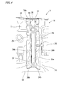
- FIG. 4 is a front view of the center frame.
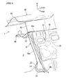
- FIG. 5 is a perspective view of the center frame.
- FIG. 6 is a cross-sectional perspective view taken along line A-A of FIG. 1 .
- FIG. 7 is a cross-sectional view taken along line B-B of FIG. 2 .
- a cross-sectional shape in the case where it is viewed in cross-section perpendicular to the direction of the length of the center frame 28, is formed in a substantially hat shape, and it is formed so as to span the bent part 27 of the vertical wall 11 and the tunnel part 13. That is, the center frame 28 is configured of a frame body 36 formed in a substantially U shape in cross-section, and flange parts 29 that bend and extend toward the outside from the two side edges of the frame body 36.
- the center frame 28 has a pair of side walls 36b facing each other, and a base wall 36a that connects the pair of side walls 36b.
- the frame body 36 is disposed such that its open side faces the vertical wall 11 side, and the bottom wall 36a of the frame body 36 slopes down toward the rear.
- the height of the side walls 36b of the frame body 36 is set such that it gradually becomes higher as it proceeds downward so as to correspond to the downward slope of the bottom wall 36a, and it follows the unevenness of the vertical wall 11.
- the center frame 28 slopes down toward the rear, while the flange parts 29 overlap the vertical wall 11.
- a ridge part (ridgeline) 37 which is a connecting portion of the bottom wall 36a and the side wall 36b, is formed in a straight line.
- a plurality of weld bead parts 39 is formed on the left and right side walls 36b and 36b and the flange parts 29.
- the stiffness of the center frame 28 is increased by the plurality of weld bead parts 39.
- the flange parts 29 formed in this manner are joined by spot welding in a state in which they overlap the vertical wall 11, and a closed cross-section structure part 38 is formed between the vertical wall 11 and center frame 28.
- top end flange parts 34a which are bent and extend toward the rear such that they overlap the bent parts 27 of the vertical wall 11, are formed at the top end of the center frame 28.
- the top end flange parts 34a and the bent parts 27 overlap each other, and are joined by spot welding.
- a closed cross-section structure part 35 is formed between the center frame 28 and the bent parts 27.
- bottom end flange parts 34b which extend so as to follow the top surface of the tunnel part 13, are formed at the bottom ends of the flange parts 29.
- the bottom end flange parts 34b and the top surface of the tunnel part 13 are overlapped and joined by spot welding.
- the arrangement is such that areas of the flange parts 29 that correspond to the region of the dashboard cross member 23 are exposed on the engine compartment 2 side of the dashboard lower 10.
- the areas exposed are joined to the dashboard cross member 23 by spot welding.
- Reference sign M shown in FIG. 3 denotes spot welds between the dashboard lower 10 and each of the steering joint cover 21, the dashboard cross member 23, the master cylinder stiffener 25, the damping material fixed panel 26, and the center frame 28.
- the dashboard upper assembly 40 has a lower panel 40a and an upper panel 40b, which are formed by pressing sheet metal material, and is constructed by stacking the lower panel 40a and the upper panel 40b on top of each other. Moreover, a closed cross-section structure is formed by the lower panel 40a and the upper panel 40b.
- a flange part 41 a is formed on the rims of the upper panel 40b and a flange part 41b is formed on the rims of the lower panel 40a.
- the dashboard upper assembly 40 is formed by spot welding the stacked flange part 41 a and flange part 41 b. Then, the bent part 27 of the dashboard lower 10 is joined to the flange part 41 by spot welding.
- a front glass support panel 42 is formed by pressing a sheet metal material, and has a vertical wall (second vertical wall) 43 and an extended part 44.
- the bent part 27 of the dashboard lower 10 is connected to the vertical wall 43 of the front glass support panel 42 with the dashboard upper assembly 40 between them.
- the vertical wall 43 is formed on the same plane as the vertical wall 11 of the dashboard lower 10.
- the extended part 44 is bent and extends toward the front from the top edge of the vertical wall 43.
- a flange part 45 which is bent and extends toward the rear, is formed at the bottom edge of the vertical wall 43, and the bent part 27 of the dashboard lower 10 is joined to the flange part 45 by spot welding with the dashboard upper assembly 40 between them.
- a closed cross-section structure part 35 is formed between the bent part 27 and the center frame 28 by joining the top end flange part 34a of the center frame 28 to the bent part 27 formed at the top edge part of the dashboard lower 10 (refer to FIG. 7 ), it is possible to increase the stiffness of the bent part 27 effectively. As a result, it is possible to effectively suppress the membrane vibration, with the bent part 27 of the dashboard lower 10 being the start point, when a vehicle is moving, for example.
- the bent part 27 of the dashboard lower 10 is joined to the front glass support panel 42 with the dashboard upper assembly 40 between them. That is, the flange part 45 is formed on the vertical wall 43 of the front glass support panel 42 having a high stiffness.
- the stiffness of the bent part 27 can be further increased by joining the bent part 27 of the dashboard lower 10 to the flange part 45. As a result, it is possible to suppress the membrane vibration of the dashboard lower 10 more reliably.
- the bottom end flange part 34b which extends so as to follow the top surface of the tunnel part 13, is formed at the bottom end of the flange part 29, and the bottom end flange part 34b is joined to the top surface of the tunnel part 13 by spot welding. That is, the bottom end of the center frame 28 is supported by the tunnel part 13 having a high stiffness. As a result, the stiffness of the center frame 28 can be increased, so it is possible to suppress the membrane vibration of the dashboard lower 10 even more reliably.
- the flange parts 29 of the center frame 28 are arranged such that areas corresponding to the region of the dashboard cross member 23 are exposed on the engine compartment 2 side. The areas exposed are joined to the dashboard cross member 23 by spot welding. As a result, since the dashboard cross member 23 and the center frame 28 are unified to support the dashboard lower 10, the stiffness of the whole dashboard lower 10 is further increased. Furthermore, since a front impact load transmitted from the dashboard cross member 23 is transmitted to the tunnel part 13 via the center frame 28, the vehicle body front part structure 1 can disperse the load.
- the bottom wall 36a of the frame body 36 of the center frame 28 is disposed such that it slopes down toward the rear, and furthermore, the ridge parts 37 between the bottom wall 36a and the side walls 36b, which configures the frame body 36, are formed in straight lines. In this manner, it is possible to increase the support effect of the center frame 28 with respect to the dashboard lower 10 reliably by the degree of inclination of the center frame 28. Moreover, it is possible to transmit a front impact load transmitted from the dashboard cross member 23 to the tunnel part 13 via the center frame 28 efficiently.
- the left and right front side frames 4a and 4b are joined to the end parts on the central side in the vehicle width direction of the left and right gussets 18 and 19 respectively.
- the left and right front pillars 5a and 5b are joined to the end parts on the outside in the vehicle width direction (refer to FIG. 1 and FIG. 3 ).
- the vehicle body front part structure 1 can disperse the load.
- the front impact load transmitted from the right front side frame 4b on the right side is transmitted to the front pillar 5b on the right side via the gusset 18b on the right side, the vehicle body front part structure 1 can disperse the load.
- the present invention is not limited to the above-described embodiment. It includes a range of changes and modifications to the above-described embodiment provided they do not depart from the gist of the present invention.
- the above-described embodiment is described using a construction in which the lower panel 40a and the upper panel 40b are overlapped as a dashboard upper assembly 40 to which the bent part 27 of the dashboard lower 10 is connected.
- this is not a limitation, and a dashboard assembly constructed using only sheet metal material may be used instead of the dashboard upper assembly 40.
Landscapes
- Engineering & Computer Science (AREA)
- Chemical & Material Sciences (AREA)
- Combustion & Propulsion (AREA)
- Transportation (AREA)
- Mechanical Engineering (AREA)
- Body Structure For Vehicles (AREA)
Abstract
Description
- This invention relates to a vehicle body front part structure.
Priority is claimed on Japanese Patent Application No.2010-143870, filed June 24, 2010 - In general, a vehicle body has a cabin (compartment) where passengers ride, an engine compartment, which is arranged at the front of this cabin and houses an engine and the like, and a floor part provided underneath the cabin. Furthermore, a pair of hinge pillars is provided in the two corners of the front part of the cabin in the vehicle width direction, so as to extend in the vertical direction, which support the side doors via hinges, and a cowl with a closed cross-section structure extending in the vehicle width direction spans the top parts of the two hinge pillars. Moreover, a dashboard is provided in the area enclosed by the floor part, the pair of hinge pillars, and the cowl, which separates the engine compartment from the cabin.
- Since the dashboard is a part that only separates the engine compartment from the cabin, in many cases it is formed from thin sheet for lightness. As a result, there is a possibility that the dashboard membrane vibrates when moving. Therefore, in order to suppress the membrane vibration, a stiffening member extending in the vertical direction is provided in the dashboard. This can increase the stiffness of the dashboard.
The stiffening member is formed with a U-shaped cross-section, which is open on the dashboard side, and forms a closed cross-section by flanges provided on the open side ends being joined to the dashboard. Furthermore, the top end of the stiffening member extends to the cowl, and is joined to the bottom surface of this cowl (for example, refer to Patent Document 1). - [Patent Document 1] Japanese Patent Publication No.
4348983 - However, in the above-described conventional technique, since a stiffening member is joined to the bottom surface of the cowl, the bottom surface of the cowl is deformed, so that there is a possibility that the dashboard membrane vibrates with the top end of the dashboard being the start point. Therefore, there is a problem in that even if the stiffness of the dashboard is increased using the stiffening member, it is difficult to suppress the membrane vibration effectively.
- Consequently, this invention has been made in consideration of the above situation, with an object of providing a vehicle body front part structure that can suppress the vibration of a dashboard membrane effectively.
- The present invention employs the following measures in order to solve the above-described problem and achieve the associated object.
That is, - (1) a vehicle body front part structure according to a first aspect of the present invention includes: a center frame which extends along a vertical direction of a vehicle, a top end flange part that bends toward a rear being formed on a top end of the center frame; and a dashboard lower which has a first vertical wall, a bent part that is bent toward the rear being formed on a top edge of the first vertical wall. The top end flange part and the bent part are joined overlapping each other, and a closed cross-section structure part is formed between the center frame and the bent part.
-
- (2) The vehicle body front part structure according to the above-described (1) may further include a front glass support panel having a second vertical wall that is formed on a same plane as the first vertical wall; and the second vertical wall of the front glass support panel is joined to the bent part of the dashboard lower.
-
- (3) In the vehicle body front part structure according to the above-described (1), a bottom end flange part may be formed at a bottom end of the center frame; a tunnel part may be provided in a center of a bottom of the dashboard lower in a width direction of the vehicle; and the bottom end flange parts may be joined to the tunnel part.
-
- (4) In the vehicle body front part structure according to the above-described (3), a vehicle body front part structure may further include a dashboard cross member which is provided with the dashboard lower and extends along the vehicle width direction. The dashboard cross member and the center frame may be joined.
-
- (5) In the vehicle body front part structure according to the above-described (3), the center frame may have a pair of walls facing each other and a bottom wall which joins bottom ends of the pair of side walls to each other, and may be disposed in a descending slope toward the rear; and a ridge of the center frame, which is a connecting portion of the side walls and the bottom wall, may be formed in a straight line.
- According to the vehicle body front part structure in the above-described (1), since a closed cross-section structure part is formed between the bent part which is a start point of membrane vibration of the first vertical wall of the dashboard lower, and the center frame, it is possible to increase the stiffness of the bent part. As a result, it is possible to suppress the vibration of the dashboard lower membrane effectively.
- According to the vehicle body front part structure according to the above-described (2), by making use of a second vertical wall of the front glass panel having a high stiffness, it is possible to further increase the stiffness of the bent part. As a result, it is possible to suppress the vibration of the dashboard lower membrane more reliably.
- According to the vehicle body front part structure in the above-described (3), it is possible to support the bottom end of the center frame by a tunnel part having a high stiffness. As a result, the stiffness of the center frame can be increased, so that it is possible to suppress the vibration of the dashboard lower membrane even more reliably.
- According to the vehicle body front part structure in the above-described (4), it is possible to further increase the stiffness of the whole dashboard lower. Moreover, since a front impact load transmitted from the dashboard cross member is transmitted to the tunnel part via the center frame, it is possible to disperse the front impact load.
- According to the vehicle body front part structure in the above-described (5), it is possible to increase the support effect of the center frame with respect to the dashboard lower, by the degree of inclination of the center frame. In addition, since the ridges of the center frame are formed in straight lines, it is possible to further increase the support effect of the center frame with respect to the dashboard lower. Furthermore, since a front impact load is transmitted to the tunnel part via the center frame efficiently, the vehicle body front part structure can disperse the front impact load.
-
-
FIG. 1 is a perspective view of a dashboard lower according to an embodiment of the present invention, viewed from the cabin side. -
FIG. 2 is a plan view of the dashboard lower according to the embodiment, viewed from the cabin side. -
FIG. 3 is a plan view of the dashboard lower according to the embodiment, viewed from the engine compartment side. -
FIG. 4 is a front view of a center frame according to the embodiment. -
FIG. 5 a perspective view of the center frame according to the embodiment. -
FIG. 6 is a cross-sectional perspective view taken along line A-A ofFIG. 1 . -
FIG. 7 is a cross-sectional view taken along line B-B ofFIG. 2 . - Next is a description of an embodiment of the present invention based on the drawings. In the following description, there are cases in which the front in the direction of travel of a vehicle is simply denoted as "front", rear in the direction of travel is simply "rear", right in the vehicle width direction is simply "right", left in the vehicle width direction is simply "left", up in the gravity direction is simply "up", and down in the gravity direction is simply "down".
FIG. 1 is a perspective view of a dashboard lower viewed from the cabin side,FIG. 2 is a plan view of the dashboard lower viewed from the cabin side, andFIG. 3 is a plan view of the dashboard lower viewed from the engine compartment side. - As shown in
FIG. 1 to FIG. 3 , a vehicle bodyfront part structure 1 is provided withfront side frames front pillars upper members floor panel 9.
Thefront side frames engine compartment 2. Thefront pillars front side frames upper members front side frames front side frames front pillars engine compartment 2 from acabin 3 disposed at the rear of this, and is joined to thefront side frames front pillars upper members floor panel 9 is joined to the bottom end of the dashboard lower 10. - The dashboard lower 10 is formed from a pressed sheet metal member, and has a vertical wall (first vertical wall) 11 along the vertical direction, and sloping
walls 12 extending in a slope downward to the rear from the lower part of thevertical wall 11. Furthermore,wheel housing parts - The
wheel housing parts cabin 3. Furthermore,gussets wheel housing parts
The rear ends of thefront side frames gussets front pillars gussets - As shown in
FIG. 1 and FIG. 2A, atunnel part 13 that protrudes upwards is formed in one piece centered between thesloping walls 12 of the dashboard lower 10 in the vehicle width direction, that is in the lower part of the dashboard lower 10. Astep part 14 on the driver's seat side is disposed on the left side, and astep part 15 on the passenger's seat side is disposed on the right side with thetunnel part 13 in between them. - A
steering opening part 20, which connects theengine compartment 2 with thecabin 3, is formed at the boundary of thevertical wall 11 and the slopingwall 12 in the driver's seatside step part 14 as shown inFIG. 1 . Thesteering opening part 20 is formed in order for a steering shaft and a universal joint connected to the steering shaft (not shown in the figure) to be inserted therethrough. Moreover, a steeringjoint cover 21 to cover it is installed in thesteering opening part 20 from theengine compartment 2 side.
The steeringjoint cover 21 is a cup shape formed so as to protrude toward theengine compartment 2 side, and has ajoint insertion entry 22 formed in order for the steering shaft and universal joint (not shown in the figure) to be inserted. - Furthermore, a
dashboard cross member 23, which extends in the vehicle width direction, that is, along the left and right front side frames 4a and 4b, is provided in a location corresponding to the steeringjoint cover 21 on the surface of theengine compartment 2 side of the dashboard lower 10. Thedashboard cross member 23 increases the stiffness of the dashboard lower 10, and disperses a front impact load. Moreover, the cross-section shape in the case where it is viewed in cross-section perpendicular to the direction of the length of thedashboard cross member 23 is formed in a substantially hat shape. A closedcross-section structure part 24 is formed by joining the open side of thedashboard cross member 23 facing toward the dashboard lower 10 by spot welding (refer toFIG. 5 andFIG. 6 ). To be specific, as shown inFIG. 6 , in the case where it is viewed in a parallel cross-section along the vertical direction, the closedcross-section structure part 24, which is a closed cross-section structure, is formed in thedashboard cross member 23. - Moreover, the
dashboard cross member 23 is formed so as to be divided into left and right with the steeringjoint cover 21 between the parts. That is, thedashboard cross member 23 comprises aleft cross member 23a and aright cross member 23b.
One end of each of theleft cross member 23a and theright cross member 23b is joined to the steeringjoint cover 21 by spot welding. That is, theleft cross member 23a and theright cross member 23b are connected via the steeringjoint cover 21. On the other hand, the opposite ends of each of theleft cross member 23a and theright cross member 23b are joined to the corresponding left and right front side frames 4a and 4b by spot welding. - A
concave part 31 is formed in a location corresponding to theright cross member 23b, on the surface of thecabin 3 side of the dashboard lower 10, so as to be elongated in the left and right direction. Theconcave part 31 is formed by the dashboard lower 10 protruding toward theengine compartment 2 side. By so doing, it is possible to further increase the stiffness of the region corresponding to thedashboard cross member 23 of the dashboard lower 10. - Furthermore, an
accelerator pedal bracket 32 on which an accelerator pedal (not shown in the figure) is mounted, is provided on the surface of the dashboard lower 10 above and to the right of thesteering opening part 20 on thecabin 3 side of thevertical wall 11. Moreover, a mountinghole 33 in which a brake master cylinder (not shown in the figure) is mounted, is formed in thevertical wall 11 above and to the left of thesteering opening part 20. - A
master cylinder stiffener 25 is provided at a location corresponding to the mountinghole 33 on thecabin 3 side of the surface of thevertical wall 11. An unevenness is formed in themaster cylinder stiffener 25 by pressing a sheet metal material, and the brake master cylinder (not shown in the figure) is mounted on the unevenness.
Moreover, a dampingmaterial fixing panel 26 is provided on thevertical wall 11 above and to the right of thetunnel part 13. The dampingmaterial fixing panel 26 affixes a melting sheet (not shown in the figure) attached as a damping material of the dashboard lower 10, and an unevenness is formed in the dampingmaterial fixing panel 26 by pressing a sheet metal material. - A
bent part 27, which is bent and extends toward the rear, is formed at the top edge of thevertical wall 11. Acenter frame 28, which extends along the vertical direction of the vehicle, is provided between thebent part 27 of thevertical wall 11 and thetunnel part 13. -
FIG. 4 is a front view of the center frame.FIG. 5 is a perspective view of the center frame.FIG. 6 is a cross-sectional perspective view taken along line A-A ofFIG. 1 .FIG. 7 is a cross-sectional view taken along line B-B ofFIG. 2 .
As shown inFIG. 4 to FIG. 7 , a cross-sectional shape, in the case where it is viewed in cross-section perpendicular to the direction of the length of thecenter frame 28, is formed in a substantially hat shape, and it is formed so as to span thebent part 27 of thevertical wall 11 and thetunnel part 13. That is, thecenter frame 28 is configured of aframe body 36 formed in a substantially U shape in cross-section, andflange parts 29 that bend and extend toward the outside from the two side edges of theframe body 36. - The
center frame 28 has a pair ofside walls 36b facing each other, and abase wall 36a that connects the pair ofside walls 36b.
Theframe body 36 is disposed such that its open side faces thevertical wall 11 side, and thebottom wall 36a of theframe body 36 slopes down toward the rear. Furthermore, the height of theside walls 36b of theframe body 36 is set such that it gradually becomes higher as it proceeds downward so as to correspond to the downward slope of thebottom wall 36a, and it follows the unevenness of thevertical wall 11.
As a result, thecenter frame 28 slopes down toward the rear, while theflange parts 29 overlap thevertical wall 11. Moreover, a ridge part (ridgeline) 37, which is a connecting portion of thebottom wall 36a and theside wall 36b, is formed in a straight line. - Furthermore, a plurality of
weld bead parts 39 is formed on the left andright side walls flange parts 29. The stiffness of thecenter frame 28 is increased by the plurality ofweld bead parts 39. Theflange parts 29 formed in this manner are joined by spot welding in a state in which they overlap thevertical wall 11, and a closedcross-section structure part 38 is formed between thevertical wall 11 andcenter frame 28. - Moreover, top
end flange parts 34a, which are bent and extend toward the rear such that they overlap thebent parts 27 of thevertical wall 11, are formed at the top end of thecenter frame 28. The topend flange parts 34a and thebent parts 27 overlap each other, and are joined by spot welding. In this manner, a closedcross-section structure part 35 is formed between thecenter frame 28 and thebent parts 27.
On the other hand, bottomend flange parts 34b, which extend so as to follow the top surface of thetunnel part 13, are formed at the bottom ends of theflange parts 29. The bottomend flange parts 34b and the top surface of thetunnel part 13 are overlapped and joined by spot welding. - As shown in
FIG. 3 , the arrangement is such that areas of theflange parts 29 that correspond to the region of thedashboard cross member 23 are exposed on theengine compartment 2 side of the dashboard lower 10. The areas exposed are joined to thedashboard cross member 23 by spot welding.
Reference sign M shown inFIG. 3 denotes spot welds between the dashboard lower 10 and each of the steeringjoint cover 21, thedashboard cross member 23, themaster cylinder stiffener 25, the damping material fixedpanel 26, and thecenter frame 28. - Furthermore, as shown in
FIG. 7 , thebent part 27 of the dashboard lower 10 is joined to a dashboardupper assembly 40 by spot welding. The dashboardupper assembly 40 has alower panel 40a and anupper panel 40b, which are formed by pressing sheet metal material, and is constructed by stacking thelower panel 40a and theupper panel 40b on top of each other. Moreover, a closed cross-section structure is formed by thelower panel 40a and theupper panel 40b. - A
flange part 41 a is formed on the rims of theupper panel 40b and aflange part 41b is formed on the rims of thelower panel 40a. The dashboardupper assembly 40 is formed by spot welding the stackedflange part 41 a andflange part 41 b. Then, thebent part 27 of the dashboard lower 10 is joined to the flange part 41 by spot welding. - Moreover, a front
glass support panel 42 is formed by pressing a sheet metal material, and has a vertical wall (second vertical wall) 43 and anextended part 44. Thebent part 27 of the dashboard lower 10 is connected to thevertical wall 43 of the frontglass support panel 42 with the dashboardupper assembly 40 between them.
Thevertical wall 43 is formed on the same plane as thevertical wall 11 of the dashboard lower 10. Theextended part 44 is bent and extends toward the front from the top edge of thevertical wall 43.
Aflange part 45, which is bent and extends toward the rear, is formed at the bottom edge of thevertical wall 43, and thebent part 27 of the dashboard lower 10 is joined to theflange part 45 by spot welding with the dashboardupper assembly 40 between them. - Therefore, according to the above-described embodiment, since a closed
cross-section structure part 35 is formed between thebent part 27 and thecenter frame 28 by joining the topend flange part 34a of thecenter frame 28 to thebent part 27 formed at the top edge part of the dashboard lower 10 (refer toFIG. 7 ), it is possible to increase the stiffness of thebent part 27 effectively. As a result, it is possible to effectively suppress the membrane vibration, with thebent part 27 of the dashboard lower 10 being the start point, when a vehicle is moving, for example. - Furthermore, the
bent part 27 of the dashboard lower 10 is joined to the frontglass support panel 42 with the dashboardupper assembly 40 between them. That is, theflange part 45 is formed on thevertical wall 43 of the frontglass support panel 42 having a high stiffness. The stiffness of thebent part 27 can be further increased by joining thebent part 27 of the dashboard lower 10 to theflange part 45. As a result, it is possible to suppress the membrane vibration of the dashboard lower 10 more reliably. - Moreover, the bottom
end flange part 34b, which extends so as to follow the top surface of thetunnel part 13, is formed at the bottom end of theflange part 29, and the bottomend flange part 34b is joined to the top surface of thetunnel part 13 by spot welding. That is, the bottom end of thecenter frame 28 is supported by thetunnel part 13 having a high stiffness. As a result, the stiffness of thecenter frame 28 can be increased, so it is possible to suppress the membrane vibration of the dashboard lower 10 even more reliably. - The
flange parts 29 of thecenter frame 28 are arranged such that areas corresponding to the region of thedashboard cross member 23 are exposed on theengine compartment 2 side. The areas exposed are joined to thedashboard cross member 23 by spot welding. As a result, since thedashboard cross member 23 and thecenter frame 28 are unified to support the dashboard lower 10, the stiffness of the whole dashboard lower 10 is further increased. Furthermore, since a front impact load transmitted from thedashboard cross member 23 is transmitted to thetunnel part 13 via thecenter frame 28, the vehicle bodyfront part structure 1 can disperse the load. - Moreover, the
bottom wall 36a of theframe body 36 of thecenter frame 28 is disposed such that it slopes down toward the rear, and furthermore, theridge parts 37 between thebottom wall 36a and theside walls 36b, which configures theframe body 36, are formed in straight lines. In this manner, it is possible to increase the support effect of thecenter frame 28 with respect to the dashboard lower 10 reliably by the degree of inclination of thecenter frame 28. Moreover, it is possible to transmit a front impact load transmitted from thedashboard cross member 23 to thetunnel part 13 via thecenter frame 28 efficiently. - The left and right front side frames 4a and 4b are joined to the end parts on the central side in the vehicle width direction of the left and right gussets 18 and 19 respectively. On the other hand, the left and right
front pillars FIG. 1 andFIG. 3 ). As a result, since a front impact load transmitted from the leftfront side frame 4a on the left side is transmitted to thefront pillar 5a on the left side via thegusset 18a on the left side, the vehicle bodyfront part structure 1 can disperse the load. Furthermore, since the front impact load transmitted from the rightfront side frame 4b on the right side is transmitted to thefront pillar 5b on the right side via thegusset 18b on the right side, the vehicle bodyfront part structure 1 can disperse the load. - The present invention is not limited to the above-described embodiment. It includes a range of changes and modifications to the above-described embodiment provided they do not depart from the gist of the present invention.
For example, the above-described embodiment is described using a construction in which thelower panel 40a and theupper panel 40b are overlapped as a dashboardupper assembly 40 to which thebent part 27 of the dashboard lower 10 is connected. However, this is not a limitation, and a dashboard assembly constructed using only sheet metal material may be used instead of the dashboardupper assembly 40. - Moreover, in the above-described embodiment, a case is described in which metal joins of each part are achieved by spot welding. However, this is not a limitation, and it is possible to use appropriate conventionally known metal welding methods such as TIG (tungsten inert gas) welding, MIG (metal inert gas) welding, arc welding such as plasma arc welding, laser welding, electron beam welding, and the like.
-
- 1 Vehicle body front part structure
- 10 Dashboard lower
- 11, 43 Vertical wall
- 13 Tunnel part
- 23 Dashboard cross member
- 27 Bent part
- 28 Center frame
- 34a Top end flange part
- 34b Bottom end flange part
- 37 Ridge part (ridgeline)
- 42 Front glass support panel
Claims (5)
- A vehicle body front part structure comprising:a center frame which extends along a vertical direction of a vehicle, a top end flange part that bends toward a rear being formed on a top end of the center frame; anda dashboard lower which has a first vertical wall, wherein a bent part that is bent toward the rear being formed on a top edge of the first vertical wall, whereinthe top end flange part and the bent part are joined overlapping each other, and a closed cross-section structure part is formed between the center frame and the bent part.
- The vehicle body front part structure according to claim 1, further comprising a front glass support panel having a second vertical wall that is formed on a same plane as the first vertical wall, wherein
the second vertical wall of the front glass support panel is joined to the bent part of the dashboard lower. - The vehicle body front part structure according to claim 1, wherein:a bottom end flange part is formed at a bottom end of the center frame;a tunnel part is provided in a center of a bottom of the dashboard lower in a width direction of the vehicle; andthe bottom end flange parts are joined to the tunnel part.
- The vehicle body front part structure according to claim 3, further comprising
a dashboard cross member which is provided with the dashboard lower and extends along the vehicle width direction, wherein
the dashboard cross member and the center frame are joined. - The vehicle body front part structure according to claim 3, wherein
the center frame has a pair of walls facing each other and a bottom wall which joins bottom ends of the pair of side walls to each other, and is disposed in a descending slope toward the rear; and
a ridge of the center frame, which is a connecting portion of the side walls and the bottom wall, is formed in a straight line.
Applications Claiming Priority (2)
| Application Number | Priority Date | Filing Date | Title |
|---|---|---|---|
| JP2010143870 | 2010-06-24 | ||
| PCT/JP2011/061765 WO2011162060A1 (en) | 2010-06-24 | 2011-05-23 | Structure of front section of vehicle |
Publications (2)
| Publication Number | Publication Date |
|---|---|
| EP2586681A1 true EP2586681A1 (en) | 2013-05-01 |
| EP2586681A4 EP2586681A4 (en) | 2013-11-13 |
Family
ID=45371257
Family Applications (1)
| Application Number | Title | Priority Date | Filing Date |
|---|---|---|---|
| EP11797947.6A Withdrawn EP2586681A4 (en) | 2010-06-24 | 2011-05-23 | Structure of front section of vehicle |
Country Status (5)
| Country | Link |
|---|---|
| US (1) | US8801082B2 (en) |
| EP (1) | EP2586681A4 (en) |
| JP (1) | JP5352741B2 (en) |
| CN (1) | CN102947169A (en) |
| WO (1) | WO2011162060A1 (en) |
Families Citing this family (5)
| Publication number | Priority date | Publication date | Assignee | Title |
|---|---|---|---|---|
| US8702158B2 (en) * | 2010-05-25 | 2014-04-22 | Honda Motor Co., Ltd. | Structure for vehicle body front portion |
| JP5664497B2 (en) * | 2011-08-10 | 2015-02-04 | トヨタ自動車株式会社 | Vehicle front structure |
| JP2015136988A (en) * | 2014-01-21 | 2015-07-30 | 本田技研工業株式会社 | Vehicle body front part structure |
| CN107264644A (en) * | 2017-07-27 | 2017-10-20 | 东风小康汽车有限公司重庆分公司 | A kind of body of a motor car driving cabin assembly structure |
| KR20230129652A (en) * | 2022-03-02 | 2023-09-11 | 현대자동차주식회사 | Dash panel body structure with reinforced road path connectivity |
Family Cites Families (29)
| Publication number | Priority date | Publication date | Assignee | Title |
|---|---|---|---|---|
| JPS60117224A (en) | 1983-11-29 | 1985-06-24 | Asahi Optical Co Ltd | Manual setting circuit for aperture value of camera |
| JPS60117224U (en) * | 1984-01-19 | 1985-08-08 | 三菱自動車工業株式会社 | Automobile roll stopper support structure |
| JPS6297885A (en) | 1985-10-25 | 1987-05-07 | Nippon Telegr & Teleph Corp <Ntt> | Laser beam recording member and production thereof |
| JPH0534308Y2 (en) * | 1985-12-12 | 1993-08-31 | ||
| JPH0428178A (en) | 1990-05-23 | 1992-01-30 | Fujitsu Ltd | Connector terminal structure |
| JPH0428178U (en) * | 1990-06-29 | 1992-03-05 | ||
| JP2531718Y2 (en) * | 1990-11-09 | 1997-04-09 | マツダ株式会社 | Car front body structure |
| JPH04297382A (en) | 1991-03-26 | 1992-10-21 | Suzuki Motor Corp | Vehicle body structure |
| JPH04348983A (en) | 1991-05-16 | 1992-12-03 | Tokyo Electric Co Ltd | dot printer |
| JP2589552Y2 (en) | 1993-12-28 | 1999-01-27 | トヨタ車体株式会社 | Body front structure |
| JP4297382B2 (en) | 1996-09-09 | 2009-07-15 | 大日本印刷株式会社 | Method for producing multicolor hologram recording body |
| JP3995315B2 (en) * | 1997-09-16 | 2007-10-24 | 富士重工業株式会社 | Front body structure of the vehicle |
| JP2000033884A (en) * | 1998-05-13 | 2000-02-02 | Toyota Auto Body Co Ltd | Vehicle body front structure of tilt type cab-over type vehicle |
| JP2004106704A (en) * | 2002-09-18 | 2004-04-08 | Fuji Heavy Ind Ltd | Car body front structure |
| JP4348983B2 (en) | 2003-03-31 | 2009-10-21 | マツダ株式会社 | Front body structure of automobile |
| JP3962003B2 (en) * | 2003-10-16 | 2007-08-22 | 本田技研工業株式会社 | Body structure |
| JP4501623B2 (en) | 2004-09-28 | 2010-07-14 | 日産自動車株式会社 | Dash panel structure |
| JP4096940B2 (en) | 2004-12-06 | 2008-06-04 | 日産自動車株式会社 | Car body rear structure |
| JP2007030627A (en) * | 2005-07-25 | 2007-02-08 | Mazda Motor Corp | Front body structure of automobile |
| JP4853101B2 (en) * | 2006-05-12 | 2012-01-11 | マツダ株式会社 | Front body structure of automobile |
| JP2008037153A (en) * | 2006-08-02 | 2008-02-21 | Mazda Motor Corp | Automotive front structure |
| DE602008000247D1 (en) * | 2007-09-10 | 2009-12-10 | Honda Motor Co Ltd | Front part construction of a vehicle |
| JP4724166B2 (en) | 2007-09-20 | 2011-07-13 | 本田技研工業株式会社 | Brake master cylinder mounting structure |
| CN201296297Y (en) * | 2008-10-21 | 2009-08-26 | 比亚迪股份有限公司 | Front panel strengthening structure and front panel assembly of vehicle body |
| JP4677025B2 (en) * | 2008-10-30 | 2011-04-27 | 本田技研工業株式会社 | Body front structure |
| KR20100058973A (en) * | 2008-11-25 | 2010-06-04 | 현대자동차주식회사 | Frame of dash panel for a vehicle |
| KR20100060286A (en) * | 2008-11-27 | 2010-06-07 | 현대자동차주식회사 | Dash panel support structure |
| JP5120491B2 (en) | 2009-09-02 | 2013-01-16 | トヨタ自動車株式会社 | Vehicle front structure |
| CN101734291A (en) * | 2010-01-04 | 2010-06-16 | 重庆长安汽车股份有限公司 | Vehicle front wallboard with strengthening structure |
-
2011
- 2011-05-23 JP JP2012521381A patent/JP5352741B2/en not_active Expired - Fee Related
- 2011-05-23 US US13/704,727 patent/US8801082B2/en active Active
- 2011-05-23 CN CN2011800303672A patent/CN102947169A/en active Pending
- 2011-05-23 EP EP11797947.6A patent/EP2586681A4/en not_active Withdrawn
- 2011-05-23 WO PCT/JP2011/061765 patent/WO2011162060A1/en not_active Ceased
Also Published As
| Publication number | Publication date |
|---|---|
| JP5352741B2 (en) | 2013-11-27 |
| EP2586681A4 (en) | 2013-11-13 |
| US8801082B2 (en) | 2014-08-12 |
| US20130093216A1 (en) | 2013-04-18 |
| WO2011162060A1 (en) | 2011-12-29 |
| CN102947169A (en) | 2013-02-27 |
| JPWO2011162060A1 (en) | 2013-08-19 |
Similar Documents
| Publication | Publication Date | Title |
|---|---|---|
| CN109421818B (en) | Vehicle rear structure | |
| CN102666264B (en) | Vehicle body panel joining structure | |
| JP5352682B2 (en) | Body floor structure | |
| CN105882759B (en) | Upper vehicle body structure of vehicle | |
| CN105882760B (en) | Upper vehicle body structure of vehicle | |
| CN102510825B (en) | Structure for front section of vehicle body | |
| CN110606132B (en) | lower body structure | |
| CN102310886B (en) | Front body structure | |
| EP2559611B1 (en) | Structure of front section of vehicle body | |
| US8474563B2 (en) | Frontal structure of vehicle | |
| US8801082B2 (en) | Vehicle body front part structure | |
| CN108367787A (en) | Body construction | |
| EP2586682B1 (en) | Structure of front section of vehicle body | |
| JP4277215B2 (en) | Rear body structure of the vehicle | |
| JP7456339B2 (en) | Vehicle front body structure | |
| JP2018149945A (en) | Car body rear structure | |
| JP5081279B2 (en) | Body front structure | |
| JP2010105536A (en) | Vehicle front body structure | |
| JP2016147640A (en) | Panel structure of vehicle body |
Legal Events
| Date | Code | Title | Description |
|---|---|---|---|
| PUAI | Public reference made under article 153(3) epc to a published international application that has entered the european phase |
Free format text: ORIGINAL CODE: 0009012 |
|
| 17P | Request for examination filed |
Effective date: 20130108 |
|
| AK | Designated contracting states |
Kind code of ref document: A1 Designated state(s): AL AT BE BG CH CY CZ DE DK EE ES FI FR GB GR HR HU IE IS IT LI LT LU LV MC MK MT NL NO PL PT RO RS SE SI SK SM TR |
|
| DAX | Request for extension of the european patent (deleted) | ||
| A4 | Supplementary search report drawn up and despatched |
Effective date: 20131015 |
|
| RIC1 | Information provided on ipc code assigned before grant |
Ipc: B62D 25/08 20060101AFI20131009BHEP Ipc: B62D 25/14 20060101ALI20131009BHEP |
|
| RIC1 | Information provided on ipc code assigned before grant |
Ipc: B62D 25/14 20060101ALI20131028BHEP Ipc: B62D 25/08 20060101AFI20131028BHEP |
|
| GRAP | Despatch of communication of intention to grant a patent |
Free format text: ORIGINAL CODE: EPIDOSNIGR1 |
|
| INTG | Intention to grant announced |
Effective date: 20141112 |
|
| STAA | Information on the status of an ep patent application or granted ep patent |
Free format text: STATUS: THE APPLICATION IS DEEMED TO BE WITHDRAWN |
|
| 18D | Application deemed to be withdrawn |
Effective date: 20150324 |