EP2586680A1 - A synchronizing system for hydraulic four wheel steering - Google Patents
A synchronizing system for hydraulic four wheel steering Download PDFInfo
- Publication number
- EP2586680A1 EP2586680A1 EP12189610.4A EP12189610A EP2586680A1 EP 2586680 A1 EP2586680 A1 EP 2586680A1 EP 12189610 A EP12189610 A EP 12189610A EP 2586680 A1 EP2586680 A1 EP 2586680A1
- Authority
- EP
- European Patent Office
- Prior art keywords
- steering
- wheel
- synchronizing system
- cylinders
- synchronizing
- Prior art date
- Legal status (The legal status is an assumption and is not a legal conclusion. Google has not performed a legal analysis and makes no representation as to the accuracy of the status listed.)
- Granted
Links
Images


Classifications
-
- B—PERFORMING OPERATIONS; TRANSPORTING
- B62—LAND VEHICLES FOR TRAVELLING OTHERWISE THAN ON RAILS
- B62D—MOTOR VEHICLES; TRAILERS
- B62D7/00—Steering linkage; Stub axles or their mountings
- B62D7/06—Steering linkage; Stub axles or their mountings for individually-pivoted wheels, e.g. on king-pins
- B62D7/14—Steering linkage; Stub axles or their mountings for individually-pivoted wheels, e.g. on king-pins the pivotal axes being situated in more than one plane transverse to the longitudinal centre line of the vehicle, e.g. all-wheel steering
- B62D7/142—Steering linkage; Stub axles or their mountings for individually-pivoted wheels, e.g. on king-pins the pivotal axes being situated in more than one plane transverse to the longitudinal centre line of the vehicle, e.g. all-wheel steering specially adapted for particular vehicles, e.g. tractors, carts, earth-moving vehicles, trucks
Definitions
- the present invention relates to lawn and garden tractors and other off road vehicles having hydraulic four wheel steering, and specifically to synchronizing the steering angles of the front and rear wheels.
- Lawn and garden tractors and other off road vehicles may be equipped with mechanical four wheel steering systems having linkages extending between the front and rear wheel steering assemblies. Examples of mechanical four wheel steering systems are shown in US Patents 6,131,689 and 6,684,974 . Disadvantages of mechanical four wheel steering systems include their additional weight and cost. Mechanical four wheel steering systems also require space under the tractor frame that otherwise might be needed for high capacity mower decks.
- Hydraulic four wheel steering systems also have been proposed for lawn and garden tractors and other off road vehicles in order to reduce the weight and number of parts, save cost, and allow for higher capacity mower decks.
- hydraulic four wheel steering systems have steering angles that may become misaligned between the front and rear wheels.
- Position sensors and electronic positioning devices have been proposed to align or synchronize the front and rear wheels of lawn and garden tractors and other off road vehicles.
- synchronizing system for hydraulic four wheel steering that does not require or include position sensors or electronic positioning devices, and provides a low cost and less complex system to synchronize hydraulic four wheel steering of a lawn and garden tractor or other off road vehicle.
- a synchronizing system for hydraulic four wheel steering includes a double acting front steering cylinder mounted between a stationary member and a front wheel support assembly, and a double acting rear steering cylinder mounted between a stationary member and a rear wheel support assembly.
- a synchronizing valve assembly may be connected by hydraulic lines between the front and the rear steering cylinders, with a pair of normally closed directional relief valves that can open to synchronize the positions of the front and the rear steering cylinders.
- synchronizing system 10 for hydraulic four wheel steering may be used on off road vehicles such as lawn and garden tractor 12, mowers or other utility vehicles.
- Mower deck 13 within which a cutting blade may be rotated to cut grass or other vegetation may be suspended by the vehicle between the front wheels and tires 14, and the rear wheels and tires 16.
- the synchronizing system may be particularly advantageous for use on lawn and garden tractors that carry mid-mounted mower decks between the front and rear wheels. Additionally, the synchronizing system may be advantageous for lawn and garden tractors and similar vehicles having four wheel traction drive.
- the system also may be used on vehicles without mid-mounted mower decks or two wheel drive vehicles.
- Left and right front wheels 14 may be connected together by tie rod 18 linking between left and right front pivotal wheel support assemblies 20, and the left and right rear wheels 16 may be connected together by tie rod 22 linking between left and right rear pivotal wheel support assemblies 24.
- Lawn and garden tractor 12 may include steering wheel 26 operably connected to power steering unit 27.
- the power steering unit may include power steering directional spool valve 28 that may be moved by steering wheel 26 between a right turn position where the front wheels and rear wheels are turned to the right, and a left turn position where the front wheels and rear wheels are turned to the left.
- the power steering unit also may include steering valve directional pump 29 and high or increased pressure line 30 connecting power steering valve 28 to pump 29. Lines 21, 23 and 25 may connect valve 28 to tank or reservoir 78, a hydraulic pump (not shown), and a bypass to auxiliary hydraulics (not shown).
- the synchronizing system may include a pair of double acting or two-way steering cylinders 32, 34 and hydraulic lines forming a closed loop from power steering pump 30 through steering cylinders 32, 34 back to the pump.
- Power steering valve 28 may drive either of front steering cylinder 32 or rear steering cylinder 34, with one cylinder being the master and the other cylinder being the slave.
- Each steering cylinder may be a piston-type double acting cylinder having a movable piston or rod 33, 35 and a cylinder housing or barrel 37, 39.
- the piston or rod may be attached to the wheel support assembly, while the housing or barrel of the cylinder may be mounted to a stationary frame or axle member 41, 43 of the vehicle between the pair of front and rear wheels, or vice versa.
- Each of the steering cylinders may provide mechanical stops that may be reached when the front and rear wheels are fully turned to the right or the left.
- each front tire and wheel may be between about 5 degrees and about 20 degrees greater than the turning angle of each rear tire and wheel.
- front steering cylinder 32 may have a longer stroke than rear steering cylinder 34 between the fully extended position and fully retracted position.
- the stroke of the front steering cylinder may between about 50% and about 100% longer than the stroke of the rear steering cylinder.
- the displacement of the front steering cylinder bore and annulus may be larger than the rear steering cylinder bore and annulus.
- the front steering cylinder bore and annulus may be between about 10% and about 40% larger in displacement than the rear steering cylinder bore and annulus.
- the synchronizing system may include synchronizing valve assembly 36 having first and second directional relief valves 38, 40 preferably positioned in a manifold.
- First directional relief valve 38 may dump hydraulic fluid into the loop if there is insufficient hydraulic fluid between the front and rear steering cylinders for the cylinders to be synchronized.
- Second directional relief valve 40 may dump hydraulic fluid to tank or reservoir 42 if there is excess fluid between the front and rear steering cylinders for the cylinders to be synchronized.
- Both directional relief valves 38 and 40 are normally closed and may be spring biased to a closed position, and may open in response to hydraulic pressure in line exceeding a predetermined value such as 850 psi.
- Front primary steering line 44 may connect port 46 of power steering unit 27 to bore 48 of front steering cylinder 32.
- Front secondary steering line 50 may connect annulus 52 of front steering cylinder 32 to port 54 of synchronizing valve assembly 36.
- Rear primary steering line 56 may connect port 58 of power steering valve 28 to port 60 of synchronizing valve assembly 36.
- Rear steering valve line 62 may connect port 64 of synchronizing valve assembly 36 to annulus 66 of rear steering cylinder 34.
- Rear secondary steering line 68 may connect bore 70 of rear steering cylinder 34 to port 72 of synchronizing valve assembly 36.
- Synchronizing valve assembly 36 may include a manifold having internal passages connecting ports 60 and 64 to the inlet of first directional relief valve 38. Additional passages in the synchronizing valve assembly manifold may connect ports 54 and 72 and the outlet of first directional relief valve 38 to the inlet of second directional relief valve 40.
- the synchronizing valve assembly also may include a passage connecting the outlet of second directional relief valve 40 and port 74. Cooling return line 76 may connect port 74 to tank 42.
- Figs. 2 and 4 show an embodiment of synchronizing system 10 where steering wheel 26 and front and rear wheels 14, 16 are turned to the left. Turning the steering wheel to the left opens power steering valve 28 from power steering pump 30 to rear primary steering line 56.
- Rear primary steering line 56 may be connected to port 60 of synchronizing valve assembly 36. Passages in synchronizing valve assembly 36 may connect port 60 to port 64.
- Rear steering valve line 62 may connect port 64 of synchronizing valve assembly 36 to annulus 66 of rear steering cylinder 34. Hydraulic fluid pressure in annulus 66 forces rear steering cylinder 34 to retract. As rear steering cylinder 34 retracts, hydraulic fluid may be forced out the opposite end or bore 70 of rear steering cylinder 34.
- Rear secondary steering line 68 may connect bore 70 to port 72 of synchronizing valve assembly 36. Passages in synchronizing valve assembly 36 may connect port 72 to port 54.
- Front secondary steering line 50 may connect port 54 of synchronizing valve assembly 36 to annulus 52 of front steering cylinder 32. Hydraulic fluid pressure in annulus 52 forces front steering cylinder 32 to retract. As front steering cylinder 32 retracts, hydraulic fluid may be forced out the bore 48 of front steering cylinder 32.
- Front primary steering line 44 may connect bore 48 to port 46 of power steering valve 27, which may be connected by line 21 to tank 42.
- the synchronizing system may be used to continue retracting front steering cylinder 32.
- steering wheel 26 may be turned fully to the left and held in the full left turn position for at least about five seconds and preferably between at least about ten seconds and about fifteen seconds.
- hydraulic fluid pressure in rear primary steering line 60 may become sufficiently high to open first directional relief valve 38.
- First directional relief valve 38 connects between ports 60 and 54.
- Front secondary steering line 50 may be connected between port 54 and annulus 52 of front steering cylinder 32.
- First directional relief valve 38 may dump hydraulic fluid into the loop because there is insufficient hydraulic fluid between the front and rear steering cylinders for the cylinders to be synchronized. While the steering wheel continues to be held in a full left turn position, front steering cylinder 32 continues retracting until reaching a stop at which time the front and rear wheels may be synchronized in a left turn position.
- FIGs. 3 and 5 show an embodiment of synchronizing system 10 where steering wheel 26 and the front and rear wheels 14, 16 are turned to the right. Turning the steering wheel to right left opens power steering valve 28 from power steering pump 30 to front primary steering line 44.
- Front primary steering line 44 may be connected to bore 48 of front steering cylinder 32. Hydraulic fluid pressure in bore 48 forces front steering cylinder 32 to extend. As front steering cylinder 32 extends, hydraulic fluid may be forced out annulus 52 of front steering cylinder 32.
- Front secondary steering line 50 may connect annulus 52 to port 54 of synchronizing valve assembly 36. Passages in synchronizing valve assembly 36 may connect port 54 to port 72.
- Rear secondary steering line 68 may connect port 72 of synchronizing valve assembly 36 to bore 70 of rear steering cylinder 34.
- Hydraulic fluid pressure in bore 70 forces rear steering cylinder 34 to extend. As rear steering cylinder 34 extends, hydraulic fluid may be forced out the opposite end or annulus 66 of rear steering cylinder 34.
- Rear steering valve line 62 may connect annulus 66 to port 64 of synchronizing valve assembly 36. Passages in synchronizing valve assembly 36 may connect port 64 to port 60.
- Rear steering valve line 56 may connect port 60 of synchronizing valve assembly 36 to port 58 of power steering unit 27, which may be connected by line 21 to tank 42.
- the synchronizing system may be used to continue extending front steering cylinder 32.
- steering wheel 26 may be turned fully to the right and held in the full right turn position for at least about five seconds and preferably between at least about ten seconds and about fifteen seconds.
- hydraulic fluid pressure in front secondary steering line 50 may become sufficiently high to open second directional relief valve 40.
- Second directional relief valve 40 connects between ports 54 and 74. Cooling return line 76 may connect port 74 to tank 42.
- Second directional relief valve 40 may dump hydraulic fluid to tank or reservoir 42 because there is excess fluid between the front and rear steering cylinders for the cylinders to be synchronized. While the steering wheel continues to be held in a full right turn position, front steering cylinder 32 continues extending until reaching a stop at which time the front and rear wheels may be synchronized in a right turn position.
- the synchronizing system also may be used to continue retracting or extending rear steering cylinder 34. While the steering wheel continues to be held in a full left turn or right turn position, the front steering cylinder or rear steering cylinder may continue retracting or extending until reaching a stop at which time the front and rear wheels may be synchronized in a left turn or right turn position.
- the front and rear steering cylinders may be retracted when turning the wheels to the left and extended when turning the wheels to the right, but the synchronizing system also may have the front and rear steering cylinders extended when turning the wheels to the left and retracted when turning the wheels to the right.
Landscapes
- Engineering & Computer Science (AREA)
- Chemical & Material Sciences (AREA)
- Combustion & Propulsion (AREA)
- Transportation (AREA)
- Mechanical Engineering (AREA)
- Steering-Linkage Mechanisms And Four-Wheel Steering (AREA)
Abstract
Description
- The present invention relates to lawn and garden tractors and other off road vehicles having hydraulic four wheel steering, and specifically to synchronizing the steering angles of the front and rear wheels.
- Lawn and garden tractors and other off road vehicles may be equipped with mechanical four wheel steering systems having linkages extending between the front and rear wheel steering assemblies. Examples of mechanical four wheel steering systems are shown in
US Patents 6,131,689 and6,684,974 . Disadvantages of mechanical four wheel steering systems include their additional weight and cost. Mechanical four wheel steering systems also require space under the tractor frame that otherwise might be needed for high capacity mower decks. - Hydraulic four wheel steering systems also have been proposed for lawn and garden tractors and other off road vehicles in order to reduce the weight and number of parts, save cost, and allow for higher capacity mower decks. However, hydraulic four wheel steering systems have steering angles that may become misaligned between the front and rear wheels.
- Position sensors and electronic positioning devices have been proposed to align or synchronize the front and rear wheels of lawn and garden tractors and other off road vehicles. However, there is a need for synchronizing system for hydraulic four wheel steering that does not require or include position sensors or electronic positioning devices, and provides a low cost and less complex system to synchronize hydraulic four wheel steering of a lawn and garden tractor or other off road vehicle.
- It is therefore the object of the present invention to comply with one or all of these needs.
- This object is met according to the invention by the teaching of
claim 1, while features developing the solution in an advantageous manner are set forth in the further claims. - A synchronizing system for hydraulic four wheel steering includes a double acting front steering cylinder mounted between a stationary member and a front wheel support assembly, and a double acting rear steering cylinder mounted between a stationary member and a rear wheel support assembly. A synchronizing valve assembly may be connected by hydraulic lines between the front and the rear steering cylinders, with a pair of normally closed directional relief valves that can open to synchronize the positions of the front and the rear steering cylinders.
-
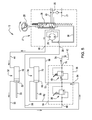
Fig. 1 is a bottom view of a synchronizing system for hydraulic four wheel steering according to a first embodiment of the invention. -
Fig. 2 is a bottom view of a synchronizing system for hydraulic four wheel steering according to a first embodiment of the invention, with the wheels fully turned to the left. -
Fig. 3 is a bottom view of a synchronizing system for hydraulic four wheel steering according to a first embodiment of the invention, with the wheels fully turned to the right. -
Fig. 4 is a schematic drawing of a synchronizing system for hydraulic four wheel steering according to a first embodiment of the invention, with the first directional relief valve open to synchronize both steering cylinders in fully retracted positions. -
Fig. 5 is a schematic drawing of a synchronizing system for hydraulic four wheel steering according to a first embodiment of the invention, with the second directional relief valve open to synchronize both steering cylinders in fully extended positions. - In a embodiment shown in
Figs. 1-5 , synchronizingsystem 10 for hydraulic four wheel steering may be used on off road vehicles such as lawn andgarden tractor 12, mowers or other utility vehicles.Mower deck 13 within which a cutting blade may be rotated to cut grass or other vegetation may be suspended by the vehicle between the front wheels andtires 14, and the rear wheels andtires 16. The synchronizing system may be particularly advantageous for use on lawn and garden tractors that carry mid-mounted mower decks between the front and rear wheels. Additionally, the synchronizing system may be advantageous for lawn and garden tractors and similar vehicles having four wheel traction drive. The system also may be used on vehicles without mid-mounted mower decks or two wheel drive vehicles. Left and rightfront wheels 14 may be connected together bytie rod 18 linking between left and right front pivotal wheel support assemblies 20, and the left and rightrear wheels 16 may be connected together bytie rod 22 linking between left and right rear pivotalwheel support assemblies 24. - Lawn and
garden tractor 12 may includesteering wheel 26 operably connected topower steering unit 27. The power steering unit may include power steeringdirectional spool valve 28 that may be moved bysteering wheel 26 between a right turn position where the front wheels and rear wheels are turned to the right, and a left turn position where the front wheels and rear wheels are turned to the left. The power steering unit also may include steering valvedirectional pump 29 and high or increasedpressure line 30 connectingpower steering valve 28 to pump 29.Lines valve 28 to tank orreservoir 78, a hydraulic pump (not shown), and a bypass to auxiliary hydraulics (not shown). - The synchronizing system may include a pair of double acting or two-
way steering cylinders power steering pump 30 throughsteering cylinders Power steering valve 28 may drive either offront steering cylinder 32 orrear steering cylinder 34, with one cylinder being the master and the other cylinder being the slave. Each steering cylinder may be a piston-type double acting cylinder having a movable piston orrod barrel axle member - The turning angle of each front tire and wheel may be between about 5 degrees and about 20 degrees greater than the turning angle of each rear tire and wheel. For each front wheel to have a greater turning angle,
front steering cylinder 32 may have a longer stroke thanrear steering cylinder 34 between the fully extended position and fully retracted position. For example, the stroke of the front steering cylinder may between about 50% and about 100% longer than the stroke of the rear steering cylinder. Additionally, the displacement of the front steering cylinder bore and annulus may be larger than the rear steering cylinder bore and annulus. For example, the front steering cylinder bore and annulus may be between about 10% and about 40% larger in displacement than the rear steering cylinder bore and annulus. - The synchronizing system may include synchronizing
valve assembly 36 having first and seconddirectional relief valves directional relief valve 38 may dump hydraulic fluid into the loop if there is insufficient hydraulic fluid between the front and rear steering cylinders for the cylinders to be synchronized. Seconddirectional relief valve 40 may dump hydraulic fluid to tank orreservoir 42 if there is excess fluid between the front and rear steering cylinders for the cylinders to be synchronized. Bothdirectional relief valves - Front
primary steering line 44 may connectport 46 ofpower steering unit 27 to bore 48 offront steering cylinder 32. Frontsecondary steering line 50 may connectannulus 52 offront steering cylinder 32 toport 54 of synchronizingvalve assembly 36. Rearprimary steering line 56 may connectport 58 ofpower steering valve 28 toport 60 of synchronizingvalve assembly 36. Rearsteering valve line 62 may connectport 64 of synchronizingvalve assembly 36 toannulus 66 ofrear steering cylinder 34. Rearsecondary steering line 68 may connectbore 70 ofrear steering cylinder 34 toport 72 of synchronizingvalve assembly 36. - Synchronizing
valve assembly 36 may include a manifold having internalpassages connecting ports directional relief valve 38. Additional passages in the synchronizing valve assembly manifold may connectports directional relief valve 38 to the inlet of seconddirectional relief valve 40. The synchronizing valve assembly also may include a passage connecting the outlet of seconddirectional relief valve 40 andport 74.Cooling return line 76 may connectport 74 totank 42. -
Figs. 2 and4 show an embodiment of synchronizingsystem 10 wheresteering wheel 26 and front andrear wheels power steering valve 28 frompower steering pump 30 to rearprimary steering line 56. Rearprimary steering line 56 may be connected toport 60 of synchronizingvalve assembly 36. Passages in synchronizingvalve assembly 36 may connectport 60 toport 64. Rearsteering valve line 62 may connectport 64 of synchronizingvalve assembly 36 toannulus 66 ofrear steering cylinder 34. Hydraulic fluid pressure inannulus 66 forcesrear steering cylinder 34 to retract. Asrear steering cylinder 34 retracts, hydraulic fluid may be forced out the opposite end or bore 70 ofrear steering cylinder 34. Rearsecondary steering line 68 may connectbore 70 toport 72 of synchronizingvalve assembly 36. Passages in synchronizingvalve assembly 36 may connectport 72 toport 54. Frontsecondary steering line 50 may connectport 54 of synchronizingvalve assembly 36 toannulus 52 offront steering cylinder 32. Hydraulic fluid pressure inannulus 52 forcesfront steering cylinder 32 to retract. Asfront steering cylinder 32 retracts, hydraulic fluid may be forced out thebore 48 offront steering cylinder 32. Frontprimary steering line 44 may connectbore 48 toport 46 ofpower steering valve 27, which may be connected byline 21 to tank 42. - If
rear steering cylinder 34 is completely retracted and reaches a stop beforefront steering cylinder 32 is completely retracted, the synchronizing system may be used to continue retractingfront steering cylinder 32. As shown inFig. 4 ,steering wheel 26 may be turned fully to the left and held in the full left turn position for at least about five seconds and preferably between at least about ten seconds and about fifteen seconds. As a result, hydraulic fluid pressure in rearprimary steering line 60 may become sufficiently high to open firstdirectional relief valve 38. Firstdirectional relief valve 38 connects betweenports secondary steering line 50 may be connected betweenport 54 andannulus 52 offront steering cylinder 32. Firstdirectional relief valve 38 may dump hydraulic fluid into the loop because there is insufficient hydraulic fluid between the front and rear steering cylinders for the cylinders to be synchronized. While the steering wheel continues to be held in a full left turn position,front steering cylinder 32 continues retracting until reaching a stop at which time the front and rear wheels may be synchronized in a left turn position. -
Figs. 3 and5 show an embodiment of synchronizingsystem 10 wheresteering wheel 26 and the front andrear wheels power steering valve 28 frompower steering pump 30 to frontprimary steering line 44. Frontprimary steering line 44 may be connected to bore 48 offront steering cylinder 32. Hydraulic fluid pressure inbore 48 forcesfront steering cylinder 32 to extend. Asfront steering cylinder 32 extends, hydraulic fluid may be forced outannulus 52 offront steering cylinder 32. Frontsecondary steering line 50 may connectannulus 52 to port 54 of synchronizingvalve assembly 36. Passages in synchronizingvalve assembly 36 may connectport 54 toport 72. Rearsecondary steering line 68 may connectport 72 of synchronizingvalve assembly 36 to bore 70 ofrear steering cylinder 34. Hydraulic fluid pressure inbore 70 forcesrear steering cylinder 34 to extend. Asrear steering cylinder 34 extends, hydraulic fluid may be forced out the opposite end orannulus 66 ofrear steering cylinder 34. Rearsteering valve line 62 may connectannulus 66 to port 64 of synchronizingvalve assembly 36. Passages in synchronizingvalve assembly 36 may connectport 64 toport 60. Rearsteering valve line 56 may connectport 60 of synchronizingvalve assembly 36 to port 58 ofpower steering unit 27, which may be connected byline 21 totank 42. - If
rear steering cylinder 34 is completely extended and reaches a stop beforefront steering cylinder 32 is completely extended, the synchronizing system may be used to continue extendingfront steering cylinder 32. As shown inFig. 5 ,steering wheel 26 may be turned fully to the right and held in the full right turn position for at least about five seconds and preferably between at least about ten seconds and about fifteen seconds. As a result, hydraulic fluid pressure in frontsecondary steering line 50 may become sufficiently high to open seconddirectional relief valve 40. Seconddirectional relief valve 40 connects betweenports Cooling return line 76 may connectport 74 totank 42. Seconddirectional relief valve 40 may dump hydraulic fluid to tank orreservoir 42 because there is excess fluid between the front and rear steering cylinders for the cylinders to be synchronized. While the steering wheel continues to be held in a full right turn position,front steering cylinder 32 continues extending until reaching a stop at which time the front and rear wheels may be synchronized in a right turn position. - If
front steering cylinder 32 is completely retracted or extended and reaches a stop beforerear steering cylinder 34 is completely retracted or extended, the synchronizing system also may be used to continue retracting or extendingrear steering cylinder 34. While the steering wheel continues to be held in a full left turn or right turn position, the front steering cylinder or rear steering cylinder may continue retracting or extending until reaching a stop at which time the front and rear wheels may be synchronized in a left turn or right turn position. In a preferred embodiment, the front and rear steering cylinders may be retracted when turning the wheels to the left and extended when turning the wheels to the right, but the synchronizing system also may have the front and rear steering cylinders extended when turning the wheels to the left and retracted when turning the wheels to the right.
Claims (15)
- A synchronizing system for hydraulic four wheel steering comprising:a double acting front steering cylinder mounted between a stationary member and a front wheel support assembly;a double acting rear steering cylinder mounted between a stationary member and a rear wheel support assembly; anda synchronizing valve assembly connected by hydraulic lines between the front and the rear steering cylinders, the assembly having a pair of directional relief valves that can open to synchronize the positions of the front and the rear steering cylinders.
- The synchronizing system according to claim 1, comprising a power steering valve operably connected to a steering wheel that may be turned to move the power steering valve between a full left turn position and a full right turn position.
- The synchronizing system according to claim 2, wherein each of the front and the rear steering cylinders connected by hydraulic lines to the power steering valve and moveable between a retracted position and an extended position in response to the position of the power steering valve.
- The synchronizing system according to one of the claims 1 to 3, wherein the pair of directional relief valves include a first directional relief valve that opens to synchronize both of the front and the rear steering cylinders in a fully extended position.
- The synchronizing system according to one of the claims 1 to 4, wherein the pair of directional relief valves include a second directional relief valve that opens to synchronize both of the front and the rear steering cylinders in a fully retracted position.
- The synchronizing system according to one of the claims 1 to 5, wherein the front steering cylinder has a longer stroke than the rear steering cylinder.
- The synchronizing system according to one of the claims 1 to 6, wherein one end of each steering cylinder is mounted to a wheel support assembly and an opposite end of each steering cylinder is mounted to a stationary member between a left wheel and a right wheel of a lawn and garden tractor having a mid-mounted mower deck.
- The synchronizing system according to claim 7, further comprising a pair of front wheels and a pair of rear wheels on the lawn and garden tractor, each front wheel having a greater turning angle than each rear wheel.
- The synchronizing system according to one of the claims 1 to 8, wherein the first directional relief valve opens in response to hydraulic fluid pressure acting on the first directional relief valve if only one of the steering cylinders is fully retracted.
- The synchronizing system according to one of the claims 1 to 9, wherein the second directional relief valve opens in response to hydraulic fluid pressure acting on the second directional relief valve if only one of the steering cylinders is fully extended.
- The synchronizing system according to one of the claims 1 to 10, further comprising a steering wheel operably connected to a power steering unit connected by hydraulic lines to the front and the rear steering cylinders and the synchronizing valve assembly, the steering wheel may be turned fully in one direction to synchronize both of the front and the rear steering cylinders in an extended position, and turned fully in an opposite direction to synchronize both of the front and the rear steering cylinders in a retracted position.
- The synchronizing system according to one of the claims 1 to 11, wherein one of the first and the second directional relief valves opens when turning a steering wheel fully to the left if there is not enough hydraulic fluid between the front and the rear steering cylinders for the front and the rear cylinders to be synchronized.
- The synchronizing system according to one of the claims 1 to 12, wherein one of the first and the second directional relief valves opens when turning a steering wheel fully to the right if there is excess hydraulic fluid between the front and the rear steering cylinders for the front and the rear cylinders to be synchronized.
- The synchronizing system according to one of the claims 1 to 13, wherein the pair of directional relief valves are in a synchronizing valve assembly having a manifold with passages extending between a plurality of ports.
- The synchronizing system according to one of the claims 1 to 14, wherein the hydraulic lines form a loop including the power steering valve, the pump, and the pair of two-way steering cylinders if the pair of directional relief valves are closed.
Applications Claiming Priority (1)
| Application Number | Priority Date | Filing Date | Title |
|---|---|---|---|
| US13/284,179 US8651223B2 (en) | 2011-10-28 | 2011-10-28 | Synchronizing system for hydraulic four wheel steering |
Publications (3)
| Publication Number | Publication Date |
|---|---|
| EP2586680A1 true EP2586680A1 (en) | 2013-05-01 |
| EP2586680A8 EP2586680A8 (en) | 2013-10-30 |
| EP2586680B1 EP2586680B1 (en) | 2017-06-21 |
Family
ID=48171263
Family Applications (1)
| Application Number | Title | Priority Date | Filing Date |
|---|---|---|---|
| EP12189610.4A Active EP2586680B1 (en) | 2011-10-28 | 2012-10-23 | A synchronizing system for hydraulic four wheel steering |
Country Status (2)
| Country | Link |
|---|---|
| US (1) | US8651223B2 (en) |
| EP (1) | EP2586680B1 (en) |
Cited By (2)
| Publication number | Priority date | Publication date | Assignee | Title |
|---|---|---|---|---|
| CN107140017A (en) * | 2017-04-12 | 2017-09-08 | 西华大学 | The orchard management power platform of four-wheel steering four-wheel drive |
| CN108891481A (en) * | 2018-07-17 | 2018-11-27 | 四川川龙拖拉机制造有限公司 | 4-wheel Steering Control System, carriage and four-wheel tractor |
Families Citing this family (3)
| Publication number | Priority date | Publication date | Assignee | Title |
|---|---|---|---|---|
| DE102017109800B4 (en) * | 2017-05-08 | 2019-01-24 | Danfoss Power Solutions Aps | Hydraulic steering unit |
| US10464600B2 (en) | 2017-05-12 | 2019-11-05 | Cnh Industrial America Llc | Four wheel steering with rear mounted control valves |
| US11731691B2 (en) * | 2019-09-11 | 2023-08-22 | Super ATV, LLC | Rear end steering and mounting system |
Citations (9)
| Publication number | Priority date | Publication date | Assignee | Title |
|---|---|---|---|---|
| DE1812208A1 (en) * | 1968-04-02 | 1969-12-18 | Whiteman Mfg Company | Device for synchronizing hydraulic cylinder drives |
| GB1240582A (en) * | 1968-05-28 | 1971-07-28 | Massey Ferguson Inc | Synchronized four-wheel steering system |
| DE2052085A1 (en) * | 1970-10-23 | 1972-04-27 | Zahnradfabrik Friedrichshafen Ag, 7990 Friedrichshafen | Power-operated steering device for vehicles with steerable axles |
| US4006664A (en) * | 1975-04-03 | 1977-02-08 | Pettibone Corporation | Steering system including tandem hydraulic cylinders with self-synchronization |
| US4531604A (en) * | 1984-02-16 | 1985-07-30 | Marine Travelift, Inc. | Hydraulic steering synchronization system |
| US6131689A (en) | 1998-12-11 | 2000-10-17 | Deere & Company | All-wheel-steer biasing mechanism |
| US20030070865A1 (en) * | 2001-10-17 | 2003-04-17 | Deere & Company | Phase maintaining control for a hydraulic steering system |
| US6684974B1 (en) | 2002-07-24 | 2004-02-03 | Deere & Company | Four-wheel steering system for utility vehicle |
| WO2006102514A1 (en) * | 2005-03-23 | 2006-09-28 | Clark Equipment Company | Self-synchronizing hydraulic system |
Family Cites Families (5)
| Publication number | Priority date | Publication date | Assignee | Title |
|---|---|---|---|---|
| US4776418A (en) | 1987-12-28 | 1988-10-11 | Winckler Peter S | Four wheel steering having closed hydraulic system with pressure control assembly |
| US5174595A (en) * | 1991-07-17 | 1992-12-29 | Deere & Company | Four wheel steering mechanism |
| US5489006A (en) * | 1993-07-23 | 1996-02-06 | Textron Inc. | System and apparatus for limiting vehicle turning radius |
| DE4414161C1 (en) * | 1994-04-22 | 1995-11-02 | Zahnradfabrik Friedrichshafen | Multi-axle steering system for vehicles |
| KR100292695B1 (en) * | 1995-02-28 | 2001-06-15 | 토니헬샴 | Rear wheel automatic alignment device for four-wheel steering vehicle |
-
2011
- 2011-10-28 US US13/284,179 patent/US8651223B2/en active Active
-
2012
- 2012-10-23 EP EP12189610.4A patent/EP2586680B1/en active Active
Patent Citations (9)
| Publication number | Priority date | Publication date | Assignee | Title |
|---|---|---|---|---|
| DE1812208A1 (en) * | 1968-04-02 | 1969-12-18 | Whiteman Mfg Company | Device for synchronizing hydraulic cylinder drives |
| GB1240582A (en) * | 1968-05-28 | 1971-07-28 | Massey Ferguson Inc | Synchronized four-wheel steering system |
| DE2052085A1 (en) * | 1970-10-23 | 1972-04-27 | Zahnradfabrik Friedrichshafen Ag, 7990 Friedrichshafen | Power-operated steering device for vehicles with steerable axles |
| US4006664A (en) * | 1975-04-03 | 1977-02-08 | Pettibone Corporation | Steering system including tandem hydraulic cylinders with self-synchronization |
| US4531604A (en) * | 1984-02-16 | 1985-07-30 | Marine Travelift, Inc. | Hydraulic steering synchronization system |
| US6131689A (en) | 1998-12-11 | 2000-10-17 | Deere & Company | All-wheel-steer biasing mechanism |
| US20030070865A1 (en) * | 2001-10-17 | 2003-04-17 | Deere & Company | Phase maintaining control for a hydraulic steering system |
| US6684974B1 (en) | 2002-07-24 | 2004-02-03 | Deere & Company | Four-wheel steering system for utility vehicle |
| WO2006102514A1 (en) * | 2005-03-23 | 2006-09-28 | Clark Equipment Company | Self-synchronizing hydraulic system |
Cited By (3)
| Publication number | Priority date | Publication date | Assignee | Title |
|---|---|---|---|---|
| CN107140017A (en) * | 2017-04-12 | 2017-09-08 | 西华大学 | The orchard management power platform of four-wheel steering four-wheel drive |
| CN107140017B (en) * | 2017-04-12 | 2019-03-05 | 西华大学 | Four-wheel steering four-wheel drive orchard management power platform |
| CN108891481A (en) * | 2018-07-17 | 2018-11-27 | 四川川龙拖拉机制造有限公司 | 4-wheel Steering Control System, carriage and four-wheel tractor |
Also Published As
| Publication number | Publication date |
|---|---|
| US8651223B2 (en) | 2014-02-18 |
| EP2586680B1 (en) | 2017-06-21 |
| US20130105242A1 (en) | 2013-05-02 |
| EP2586680A8 (en) | 2013-10-30 |
Similar Documents
| Publication | Publication Date | Title |
|---|---|---|
| EP2586680B1 (en) | A synchronizing system for hydraulic four wheel steering | |
| US7325398B2 (en) | Closed circuit energy recovery system for a work implement | |
| US5918558A (en) | Dual-pump, flow-isolated hydraulic circuit for an agricultural tractor | |
| EP2550170B1 (en) | Hydrostatic hybrid drive system | |
| DE112008000832T5 (en) | Hydrostatic drive system with a variable charge pump | |
| EP3001042B1 (en) | Hydraulic system | |
| DE102013114040A9 (en) | Hydrostatic drive with energy storage | |
| DE102011107061A1 (en) | Drive train of a vehicle, in particular a mobile work machine | |
| US8459400B2 (en) | Force steer axle assembly with redundant centering | |
| WO1997039935A1 (en) | Vehicle steering mechanism | |
| DE102013114038A1 (en) | Hydrostatic drive in a closed circuit | |
| DK1648216T3 (en) | Agricultural mower | |
| US20180066681A1 (en) | Hydraulic stabilizing system | |
| US20120152629A1 (en) | Hydraulic system having load lock valve | |
| EP2712787B1 (en) | Agricultural vehicle with power steering | |
| NL1034161C2 (en) | Steering. | |
| RU2464194C1 (en) | Self-propelled machine axle wheels steering system | |
| US9340954B2 (en) | Regenerative circuit for articulated joint | |
| US20190118882A1 (en) | Hydraulic operating system for trailer axle | |
| CA2471082A1 (en) | A ram-based positioning system | |
| US11643141B2 (en) | Trailer assembly and associated self-erecting crane | |
| CN207526788U (en) | A kind of hydraulic system of combined tractor | |
| DE102012107777B4 (en) | STEERING SYSTEM FOR A TRAILING AXLE OF A VEHICLE | |
| US7506719B2 (en) | Self-synchronizing hydraulic system | |
| FI65527B (en) | FORDONSBUREN BAERARE FOER SKOGSBRUKSREDSKAP |
Legal Events
| Date | Code | Title | Description |
|---|---|---|---|
| PUAI | Public reference made under article 153(3) epc to a published international application that has entered the european phase |
Free format text: ORIGINAL CODE: 0009012 |
|
| AK | Designated contracting states |
Kind code of ref document: A1 Designated state(s): AL AT BE BG CH CY CZ DE DK EE ES FI FR GB GR HR HU IE IS IT LI LT LU LV MC MK MT NL NO PL PT RO RS SE SI SK SM TR |
|
| AX | Request for extension of the european patent |
Extension state: BA ME |
|
| 17P | Request for examination filed |
Effective date: 20131104 |
|
| RBV | Designated contracting states (corrected) |
Designated state(s): AL AT BE BG CH CY CZ DE DK EE ES FI FR GB GR HR HU IE IS IT LI LT LU LV MC MK MT NL NO PL PT RO RS SE SI SK SM TR |
|
| 17Q | First examination report despatched |
Effective date: 20151007 |
|
| GRAP | Despatch of communication of intention to grant a patent |
Free format text: ORIGINAL CODE: EPIDOSNIGR1 |
|
| INTG | Intention to grant announced |
Effective date: 20170111 |
|
| GRAS | Grant fee paid |
Free format text: ORIGINAL CODE: EPIDOSNIGR3 |
|
| GRAA | (expected) grant |
Free format text: ORIGINAL CODE: 0009210 |
|
| AK | Designated contracting states |
Kind code of ref document: B1 Designated state(s): AL AT BE BG CH CY CZ DE DK EE ES FI FR GB GR HR HU IE IS IT LI LT LU LV MC MK MT NL NO PL PT RO RS SE SI SK SM TR |
|
| REG | Reference to a national code |
Ref country code: GB Ref legal event code: FG4D |
|
| REG | Reference to a national code |
Ref country code: CH Ref legal event code: EP |
|
| REG | Reference to a national code |
Ref country code: IE Ref legal event code: FG4D |
|
| REG | Reference to a national code |
Ref country code: AT Ref legal event code: REF Ref document number: 902666 Country of ref document: AT Kind code of ref document: T Effective date: 20170715 |
|
| REG | Reference to a national code |
Ref country code: DE Ref legal event code: R096 Ref document number: 602012033653 Country of ref document: DE |
|
| REG | Reference to a national code |
Ref country code: NL Ref legal event code: MP Effective date: 20170621 |
|
| PG25 | Lapsed in a contracting state [announced via postgrant information from national office to epo] |
Ref country code: LT Free format text: LAPSE BECAUSE OF FAILURE TO SUBMIT A TRANSLATION OF THE DESCRIPTION OR TO PAY THE FEE WITHIN THE PRESCRIBED TIME-LIMIT Effective date: 20170621 Ref country code: FI Free format text: LAPSE BECAUSE OF FAILURE TO SUBMIT A TRANSLATION OF THE DESCRIPTION OR TO PAY THE FEE WITHIN THE PRESCRIBED TIME-LIMIT Effective date: 20170621 Ref country code: NO Free format text: LAPSE BECAUSE OF FAILURE TO SUBMIT A TRANSLATION OF THE DESCRIPTION OR TO PAY THE FEE WITHIN THE PRESCRIBED TIME-LIMIT Effective date: 20170921 Ref country code: GR Free format text: LAPSE BECAUSE OF FAILURE TO SUBMIT A TRANSLATION OF THE DESCRIPTION OR TO PAY THE FEE WITHIN THE PRESCRIBED TIME-LIMIT Effective date: 20170922 Ref country code: HR Free format text: LAPSE BECAUSE OF FAILURE TO SUBMIT A TRANSLATION OF THE DESCRIPTION OR TO PAY THE FEE WITHIN THE PRESCRIBED TIME-LIMIT Effective date: 20170621 |
|
| REG | Reference to a national code |
Ref country code: LT Ref legal event code: MG4D |
|
| REG | Reference to a national code |
Ref country code: AT Ref legal event code: MK05 Ref document number: 902666 Country of ref document: AT Kind code of ref document: T Effective date: 20170621 |
|
| PG25 | Lapsed in a contracting state [announced via postgrant information from national office to epo] |
Ref country code: LV Free format text: LAPSE BECAUSE OF FAILURE TO SUBMIT A TRANSLATION OF THE DESCRIPTION OR TO PAY THE FEE WITHIN THE PRESCRIBED TIME-LIMIT Effective date: 20170621 Ref country code: NL Free format text: LAPSE BECAUSE OF FAILURE TO SUBMIT A TRANSLATION OF THE DESCRIPTION OR TO PAY THE FEE WITHIN THE PRESCRIBED TIME-LIMIT Effective date: 20170621 Ref country code: SE Free format text: LAPSE BECAUSE OF FAILURE TO SUBMIT A TRANSLATION OF THE DESCRIPTION OR TO PAY THE FEE WITHIN THE PRESCRIBED TIME-LIMIT Effective date: 20170621 Ref country code: BG Free format text: LAPSE BECAUSE OF FAILURE TO SUBMIT A TRANSLATION OF THE DESCRIPTION OR TO PAY THE FEE WITHIN THE PRESCRIBED TIME-LIMIT Effective date: 20170921 Ref country code: RS Free format text: LAPSE BECAUSE OF FAILURE TO SUBMIT A TRANSLATION OF THE DESCRIPTION OR TO PAY THE FEE WITHIN THE PRESCRIBED TIME-LIMIT Effective date: 20170621 |
|
| PG25 | Lapsed in a contracting state [announced via postgrant information from national office to epo] |
Ref country code: RO Free format text: LAPSE BECAUSE OF FAILURE TO SUBMIT A TRANSLATION OF THE DESCRIPTION OR TO PAY THE FEE WITHIN THE PRESCRIBED TIME-LIMIT Effective date: 20170621 Ref country code: SK Free format text: LAPSE BECAUSE OF FAILURE TO SUBMIT A TRANSLATION OF THE DESCRIPTION OR TO PAY THE FEE WITHIN THE PRESCRIBED TIME-LIMIT Effective date: 20170621 Ref country code: CZ Free format text: LAPSE BECAUSE OF FAILURE TO SUBMIT A TRANSLATION OF THE DESCRIPTION OR TO PAY THE FEE WITHIN THE PRESCRIBED TIME-LIMIT Effective date: 20170621 Ref country code: AT Free format text: LAPSE BECAUSE OF FAILURE TO SUBMIT A TRANSLATION OF THE DESCRIPTION OR TO PAY THE FEE WITHIN THE PRESCRIBED TIME-LIMIT Effective date: 20170621 Ref country code: EE Free format text: LAPSE BECAUSE OF FAILURE TO SUBMIT A TRANSLATION OF THE DESCRIPTION OR TO PAY THE FEE WITHIN THE PRESCRIBED TIME-LIMIT Effective date: 20170621 |
|
| PG25 | Lapsed in a contracting state [announced via postgrant information from national office to epo] |
Ref country code: ES Free format text: LAPSE BECAUSE OF FAILURE TO SUBMIT A TRANSLATION OF THE DESCRIPTION OR TO PAY THE FEE WITHIN THE PRESCRIBED TIME-LIMIT Effective date: 20170621 Ref country code: IT Free format text: LAPSE BECAUSE OF FAILURE TO SUBMIT A TRANSLATION OF THE DESCRIPTION OR TO PAY THE FEE WITHIN THE PRESCRIBED TIME-LIMIT Effective date: 20170621 Ref country code: SM Free format text: LAPSE BECAUSE OF FAILURE TO SUBMIT A TRANSLATION OF THE DESCRIPTION OR TO PAY THE FEE WITHIN THE PRESCRIBED TIME-LIMIT Effective date: 20170621 Ref country code: PL Free format text: LAPSE BECAUSE OF FAILURE TO SUBMIT A TRANSLATION OF THE DESCRIPTION OR TO PAY THE FEE WITHIN THE PRESCRIBED TIME-LIMIT Effective date: 20170621 Ref country code: IS Free format text: LAPSE BECAUSE OF FAILURE TO SUBMIT A TRANSLATION OF THE DESCRIPTION OR TO PAY THE FEE WITHIN THE PRESCRIBED TIME-LIMIT Effective date: 20171021 |
|
| REG | Reference to a national code |
Ref country code: DE Ref legal event code: R097 Ref document number: 602012033653 Country of ref document: DE |
|
| PLBE | No opposition filed within time limit |
Free format text: ORIGINAL CODE: 0009261 |
|
| STAA | Information on the status of an ep patent application or granted ep patent |
Free format text: STATUS: NO OPPOSITION FILED WITHIN TIME LIMIT |
|
| PG25 | Lapsed in a contracting state [announced via postgrant information from national office to epo] |
Ref country code: DK Free format text: LAPSE BECAUSE OF FAILURE TO SUBMIT A TRANSLATION OF THE DESCRIPTION OR TO PAY THE FEE WITHIN THE PRESCRIBED TIME-LIMIT Effective date: 20170621 |
|
| 26N | No opposition filed |
Effective date: 20180322 |
|
| PG25 | Lapsed in a contracting state [announced via postgrant information from national office to epo] |
Ref country code: MC Free format text: LAPSE BECAUSE OF FAILURE TO SUBMIT A TRANSLATION OF THE DESCRIPTION OR TO PAY THE FEE WITHIN THE PRESCRIBED TIME-LIMIT Effective date: 20170621 |
|
| REG | Reference to a national code |
Ref country code: CH Ref legal event code: PL |
|
| REG | Reference to a national code |
Ref country code: IE Ref legal event code: MM4A |
|
| REG | Reference to a national code |
Ref country code: FR Ref legal event code: ST Effective date: 20180629 |
|
| PG25 | Lapsed in a contracting state [announced via postgrant information from national office to epo] |
Ref country code: LI Free format text: LAPSE BECAUSE OF NON-PAYMENT OF DUE FEES Effective date: 20171031 Ref country code: CH Free format text: LAPSE BECAUSE OF NON-PAYMENT OF DUE FEES Effective date: 20171031 Ref country code: LU Free format text: LAPSE BECAUSE OF NON-PAYMENT OF DUE FEES Effective date: 20171023 |
|
| REG | Reference to a national code |
Ref country code: BE Ref legal event code: MM Effective date: 20171031 |
|
| PG25 | Lapsed in a contracting state [announced via postgrant information from national office to epo] |
Ref country code: FR Free format text: LAPSE BECAUSE OF NON-PAYMENT OF DUE FEES Effective date: 20171031 Ref country code: BE Free format text: LAPSE BECAUSE OF NON-PAYMENT OF DUE FEES Effective date: 20171031 Ref country code: SI Free format text: LAPSE BECAUSE OF FAILURE TO SUBMIT A TRANSLATION OF THE DESCRIPTION OR TO PAY THE FEE WITHIN THE PRESCRIBED TIME-LIMIT Effective date: 20170621 |
|
| PG25 | Lapsed in a contracting state [announced via postgrant information from national office to epo] |
Ref country code: MT Free format text: LAPSE BECAUSE OF NON-PAYMENT OF DUE FEES Effective date: 20171023 |
|
| PG25 | Lapsed in a contracting state [announced via postgrant information from national office to epo] |
Ref country code: IE Free format text: LAPSE BECAUSE OF NON-PAYMENT OF DUE FEES Effective date: 20171023 |
|
| PG25 | Lapsed in a contracting state [announced via postgrant information from national office to epo] |
Ref country code: HU Free format text: LAPSE BECAUSE OF FAILURE TO SUBMIT A TRANSLATION OF THE DESCRIPTION OR TO PAY THE FEE WITHIN THE PRESCRIBED TIME-LIMIT; INVALID AB INITIO Effective date: 20121023 |
|
| PG25 | Lapsed in a contracting state [announced via postgrant information from national office to epo] |
Ref country code: CY Free format text: LAPSE BECAUSE OF NON-PAYMENT OF DUE FEES Effective date: 20170621 |
|
| PG25 | Lapsed in a contracting state [announced via postgrant information from national office to epo] |
Ref country code: MK Free format text: LAPSE BECAUSE OF FAILURE TO SUBMIT A TRANSLATION OF THE DESCRIPTION OR TO PAY THE FEE WITHIN THE PRESCRIBED TIME-LIMIT Effective date: 20170621 |
|
| PG25 | Lapsed in a contracting state [announced via postgrant information from national office to epo] |
Ref country code: TR Free format text: LAPSE BECAUSE OF FAILURE TO SUBMIT A TRANSLATION OF THE DESCRIPTION OR TO PAY THE FEE WITHIN THE PRESCRIBED TIME-LIMIT Effective date: 20170621 |
|
| PG25 | Lapsed in a contracting state [announced via postgrant information from national office to epo] |
Ref country code: PT Free format text: LAPSE BECAUSE OF FAILURE TO SUBMIT A TRANSLATION OF THE DESCRIPTION OR TO PAY THE FEE WITHIN THE PRESCRIBED TIME-LIMIT Effective date: 20170621 |
|
| PG25 | Lapsed in a contracting state [announced via postgrant information from national office to epo] |
Ref country code: AL Free format text: LAPSE BECAUSE OF FAILURE TO SUBMIT A TRANSLATION OF THE DESCRIPTION OR TO PAY THE FEE WITHIN THE PRESCRIBED TIME-LIMIT Effective date: 20170621 |
|
| PGFP | Annual fee paid to national office [announced via postgrant information from national office to epo] |
Ref country code: DE Payment date: 20230920 Year of fee payment: 12 |
|
| REG | Reference to a national code |
Ref country code: DE Ref legal event code: R119 Ref document number: 602012033653 Country of ref document: DE |
|
| PG25 | Lapsed in a contracting state [announced via postgrant information from national office to epo] |
Ref country code: DE Free format text: LAPSE BECAUSE OF NON-PAYMENT OF DUE FEES Effective date: 20250501 |
|
| PGFP | Annual fee paid to national office [announced via postgrant information from national office to epo] |
Ref country code: GB Payment date: 20251027 Year of fee payment: 14 |