EP2586541B1 - Bending machine for helically bending an elongated workpiece - Google Patents
Bending machine for helically bending an elongated workpiece Download PDFInfo
- Publication number
- EP2586541B1 EP2586541B1 EP12425171.1A EP12425171A EP2586541B1 EP 2586541 B1 EP2586541 B1 EP 2586541B1 EP 12425171 A EP12425171 A EP 12425171A EP 2586541 B1 EP2586541 B1 EP 2586541B1
- Authority
- EP
- European Patent Office
- Prior art keywords
- bending
- rollers
- spherical body
- partially spherical
- roller
- Prior art date
- Legal status (The legal status is an assumption and is not a legal conclusion. Google has not performed a legal analysis and makes no representation as to the accuracy of the status listed.)
- Active
Links
- 238000005452 bending Methods 0.000 title claims description 70
- 230000008878 coupling Effects 0.000 claims description 13
- 238000010168 coupling process Methods 0.000 claims description 13
- 238000005859 coupling reaction Methods 0.000 claims description 13
- 238000006073 displacement reaction Methods 0.000 claims description 5
- 125000006850 spacer group Chemical group 0.000 claims description 5
- 210000003746 feather Anatomy 0.000 claims description 2
- 230000000712 assembly Effects 0.000 description 2
- 238000000429 assembly Methods 0.000 description 2
- 238000010276 construction Methods 0.000 description 2
- 230000015556 catabolic process Effects 0.000 description 1
- 230000001419 dependent effect Effects 0.000 description 1
Images


Classifications
-
- B—PERFORMING OPERATIONS; TRANSPORTING
- B21—MECHANICAL METAL-WORKING WITHOUT ESSENTIALLY REMOVING MATERIAL; PUNCHING METAL
- B21D—WORKING OR PROCESSING OF SHEET METAL OR METAL TUBES, RODS OR PROFILES WITHOUT ESSENTIALLY REMOVING MATERIAL; PUNCHING METAL
- B21D11/00—Bending not restricted to forms of material mentioned in only one of groups B21D5/00, B21D7/00, B21D9/00; Bending not provided for in groups B21D5/00 - B21D9/00; Twisting
- B21D11/06—Bending into helical or spiral form; Forming a succession of return bends, e.g. serpentine form
-
- B—PERFORMING OPERATIONS; TRANSPORTING
- B21—MECHANICAL METAL-WORKING WITHOUT ESSENTIALLY REMOVING MATERIAL; PUNCHING METAL
- B21D—WORKING OR PROCESSING OF SHEET METAL OR METAL TUBES, RODS OR PROFILES WITHOUT ESSENTIALLY REMOVING MATERIAL; PUNCHING METAL
- B21D5/00—Bending sheet metal along straight lines, e.g. to form simple curves
- B21D5/14—Bending sheet metal along straight lines, e.g. to form simple curves by passing between rollers
Definitions
- the present invention relates to a bending machine for helically bending an elongated workpiece, according to the preamble of claim 1.
- At least three rollers are rotatable together with respective supporting shafts having vertically arranged parallel axis.
- the vertical axis rollers co-operate in bending an elongated workpiece, such as a section or a pipe.
- the vertical axis rollers are arranged horizontally coplanar so that a workpiece helix extends in height in a cylindrical shape thanks to a horizontal axis roller being idly mounted downstream of the vertical axis third roller. Since the horizontal axis roller is height adjustably mounted so to project with respect to the vertical axis rollers, a helix pitch is obtained.
- the Chinese patent CN 2476361 describes a helical bending machine with multiple heads according to the preamble of claim 1.
- bending rollers in one piece with internal helical wheels are shown coplanar inclined according to the helix pitch of a pipe being worked with respect to respective drive shafts that the helical wheels engage by their internal toothings.
- this inclined arrangement of assemblies of helical wheels and bending rollers is achieved and maintained, nor said arrangement is explained in detail in the description of the patent.
- this inclined arrangement is achieved by an inclination of the internal helical wheels with respect to the rollers that are external to them, this inclination should be able to be changed depending on the helix pitch of the workpiece, or the assemblies of helical wheels and bending rollers should be changed every time a helical bending operation is decided to be performed with a different pitch.
- the bending machine in the above mentioned Chinese patent is not of the kind in which the bending rollers are integral with the supporting shafts like in the bending machine of the present invention, but they are moved by shafts through respective toothings, the construction of the bending machine is particularly complex and susceptible to failure and breakdown.
- the technical task underlying the present invention is to propose a bending machine for helically bending an elongated workpiece which overcomes the above mentioned construction drawbacks.
- an object of the present invention is to provide a bending machine for helically bending an elongated workpiece, the bending machine being able to avoid stresses that irregularly deform the elongated workpiece, and to prevent an uneven wear of the rollers.
- a further object of the invention is to enable an automatic variation of inclination of the bending rollers of a helical bending machine in which the bending rollers rotate integrally with their supporting shafts according to the desired helix pitch for an elongated workpiece.
- a bending machine for helically bending an elongated workpiece comprising at least three bending rollers that co-operate in bending the elongated workpiece by rotating together with respective supporting shafts having parallel axes, wherein each bending roller is able to shift along its supporting shaft by means of a prismatic coupling in a limited linear stroke, and to swing by means of a rotary coupling in a limited amount of angular displacement according to an arc of meridian with respect to the axis of the supporting shaft so that each bending roller is orientated coplanar to the elongated workpiece that takes an inclined position depending on a desired helix pitch.
- FIG. 1 A machine body is denoted as 1 where generically indicated as 2 are bending rollers, whose operation is not further described because it is conventional.
- the bending rollers 2, three in number, are mounted on respective supporting shafts having parallel axes y.
- the supporting shafts generally indicated as 3 are threaded near their free ends 4.
- the pitch setting means are constituted by idle rollers 5 having horizontal axis x, being mounted on end pins 6 that are height adjustable to determine the helix pitch.
- each bending roller 2 is arranged to shift along its shaft 3 for a stroke limited by means of a prismatic coupling and to swing by means of a rotary coupling for a limited amount of angular displacement along an arc of meridian from the axis y of the supporting shaft 3.
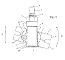
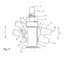
- FIGS 3 and 4 are enlarged sections of a part of the bending machine in two opposite positions of a bending roller 2 on its supporting shaft 3 having a vertical axis y.
- Each bending roller 2 is made into two specularly symmetrical half-rollers 20, 21.
- Each half-roller 20, 21 is provided with a central recess 7 in a manner that each half-roller engages a partially spherical body 8, that is substantially a barrel having a central hole (not denoted by a reference numeral) along which the partially spherical body 8 is connected to its own supporting shaft 3 by means of a prismatic coupling.
- the prismatic coupling between partially spherical body 8 and supporting shaft 3 is formed by a feather key 9.
- the supporting shaft 3 has a threaded portion 10 on which a nut 11 is screwed against a spacer 12 that limits the stroke of linear shift of the partially spherical body 8 and then the bending roller 2 formed of two half-rollers 20, 21 engaged with it by fixing screws 13, as shown in Figure 1 .
- the direction of shift is indicated by the two-points arrow F.
- the bending roller 2 can shift on the supporting shaft 3 between an abutment element 14, see the lower end position in Figure 3 , and the spacer 12, see the upper stroke end as shown in Figure 4 .
- the lower end position is obtained with a cylindrical extension 15 of the substantially spherical body 8 in contact with an abutment element 14. while the position of upper stroke end is obtained with a top portion of the substantially spherical body 8 in contact with the spacer 12.
- the partially spherical body 8 has a pocket (not indicated with a reference numeral) for housing a ball 16.
- the pocket has dimensions such as to protrude the ball 16 in an inner race 17 that is semi-closed at its ends 18, 18 to prevent the exit of the ball 16.
- the inner race 17 is made in the central cavity 7 of each half-roller 20, 21 to create a linear spherical coupling between the partially spherical body 8 and the roller 2 obtained by the union of the half-rollers 20, 21 joined by screws 13.
- the ball 16 in the inner race 17 limits the amount of angular displacement along an arc of meridian of the roller 2 with respect to the partially spherical body 8.
- the arc of meridian is schematised in a curved two-points arrow G.
- the vertical movement of the rollers in the lower and upper positions can take place continuously in order to allow the three bending rollers 2 to be conformed to the pattern of the helix according to which the elongated workpiece T is deformed.
- the shift of each bending roller 2 is permitted by the partially spherical body 8 which is contained within its cavity 7 and slides on the supporting shaft 3.
- the locking nut 11 prevents the bending rollers 2 to escape from the supporting shaft 3. Thanks to the arrangement according to the present invention, the bending rollers 2 can be oriented coplanar along the respective supporting shafts 3, to which the bending rollers 2 are rigidly connected.
- the idle rollers 5 arranged at different heights, as shown in Figure 2 determine the helix pitch to be obtained; the bending rollers 2 are arranged according to the inclination that determines that helix pitch, as they are able to shift along the respective supporting shafts 3 and turn in a linear fashion along a meridian.
- the stroke is limited by the spacer 12 and the abutment element 14, while the rotation is determined by the ball 16 engaging the race 17.
- the bending rollers 2 may perform the curvature of the elongated workpiece T by co-operating with the idle rollers 5 to get the desired helix pitch. Thanks to the invention, such a co-operation takes place with an orientation of the bending rollers 2 according to the inclination determined by the idle rollers 5 without an unnecessary stress state on the elongated piece T, or a wear on the rollers.
Description
- The present invention relates to a bending machine for helically bending an elongated workpiece, according to the preamble of
claim 1. - In the present bending machines that are disposed generally horizontally, at least three rollers are rotatable together with respective supporting shafts having vertically arranged parallel axis. The vertical axis rollers co-operate in bending an elongated workpiece, such as a section or a pipe.
- In this kind of machines the vertical axis rollers are arranged horizontally coplanar so that a workpiece helix extends in height in a cylindrical shape thanks to a horizontal axis roller being idly mounted downstream of the vertical axis third roller. Since the horizontal axis roller is height adjustably mounted so to project with respect to the vertical axis rollers, a helix pitch is obtained.
- The diverging action exerted by the horizontal axis roller counteracting the action accomplished by the vertical axis rollers that would tend to maintain the elongated workpiece on the same plane of symmetry, determines a state of stress which irregularly deforms the elongated workpiece besides to wear unevenly the vertical axis rollers due to their eccentric operation.
- The Chinese patent
CN 2476361 describes a helical bending machine with multiple heads according to the preamble ofclaim 1. In the patent drawings, bending rollers in one piece with internal helical wheels, are shown coplanar inclined according to the helix pitch of a pipe being worked with respect to respective drive shafts that the helical wheels engage by their internal toothings. However, it is not clear from the drawings how this inclined arrangement of assemblies of helical wheels and bending rollers is achieved and maintained, nor said arrangement is explained in detail in the description of the patent. If this inclined arrangement is achieved by an inclination of the internal helical wheels with respect to the rollers that are external to them, this inclination should be able to be changed depending on the helix pitch of the workpiece, or the assemblies of helical wheels and bending rollers should be changed every time a helical bending operation is decided to be performed with a different pitch. - Furthermore, since the bending machine in the above mentioned Chinese patent is not of the kind in which the bending rollers are integral with the supporting shafts like in the bending machine of the present invention, but they are moved by shafts through respective toothings, the construction of the bending machine is particularly complex and susceptible to failure and breakdown.
- In this context, the technical task underlying the present invention is to propose a bending machine for helically bending an elongated workpiece which overcomes the above mentioned construction drawbacks.
- In particular, an object of the present invention is to provide a bending machine for helically bending an elongated workpiece, the bending machine being able to avoid stresses that irregularly deform the elongated workpiece, and to prevent an uneven wear of the rollers.
- A further object of the invention is to enable an automatic variation of inclination of the bending rollers of a helical bending machine in which the bending rollers rotate integrally with their supporting shafts according to the desired helix pitch for an elongated workpiece.
- The object is generally achieved by a bending machine for helically bending an elongated workpiece, comprising at least three bending rollers that co-operate in bending the elongated workpiece by rotating together with respective supporting shafts having parallel axes, wherein each bending roller is able to shift along its supporting shaft by means of a prismatic coupling in a limited linear stroke, and to swing by means of a rotary coupling in a limited amount of angular displacement according to an arc of meridian with respect to the axis of the supporting shaft so that each bending roller is orientated coplanar to the elongated workpiece that takes an inclined position depending on a desired helix pitch.
- In the following detailed description, an embodiment of the invention is explained as defined in the enclosed dependent claims and illustrated in the accompanying drawings in which:
-
Figure 1 is a diagrammatic top plan view of a preferred embodiment of the bending machine according to the invention; -
Figure 2 is a diagrammatic side view of the bending machine inFigure 1 ; and -
Figures 3 and4 are enlarged cross-sections of a part of the bending machine in two opposite positions of a bending roller on its vertical axis shaft. - Referring initially to the plan view and the side view of
Figures 1 and2 , there is shown a bending machine for helically bending an elongated workpiece T. A machine body is denoted as 1 where generically indicated as 2 are bending rollers, whose operation is not further described because it is conventional. Thebending rollers 2, three in number, are mounted on respective supporting shafts having parallel axes y. The supporting shafts generally indicated as 3 are threaded near theirfree ends 4. - Conventionally, the three
bending rollers 2, which rotate integrally with the respective supportingshafts 3, co-operate in bending the elongated workpiece T and are apt to be oriented coplanar to the elongated workpiece arranged in an inclined position by setting means for setting the helix pitch. In the present embodiment, the pitch setting means are constituted byidle rollers 5 having horizontal axis x, being mounted onend pins 6 that are height adjustable to determine the helix pitch. - According to the invention each
bending roller 2 is arranged to shift along itsshaft 3 for a stroke limited by means of a prismatic coupling and to swing by means of a rotary coupling for a limited amount of angular displacement along an arc of meridian from the axis y of the supportingshaft 3. - In order to observe in greater detail the degrees of freedom of the bending rollers and the limitations of their possible movement, reference is made now to
Figures 3 and4 which are enlarged sections of a part of the bending machine in two opposite positions of abending roller 2 on its supportingshaft 3 having a vertical axis y. Eachbending roller 2 is made into two specularly symmetrical half-rollers roller central recess 7 in a manner that each half-roller engages a partially spherical body 8, that is substantially a barrel having a central hole (not denoted by a reference numeral) along which the partially spherical body 8 is connected to its own supportingshaft 3 by means of a prismatic coupling. The prismatic coupling between partially spherical body 8 and supportingshaft 3 is formed by afeather key 9. The supportingshaft 3 has a threadedportion 10 on which anut 11 is screwed against aspacer 12 that limits the stroke of linear shift of the partially spherical body 8 and then thebending roller 2 formed of two half-rollers screws 13, as shown inFigure 1 . The direction of shift is indicated by the two-points arrow F. - Thanks to the prismatic coupling described above, the
bending roller 2 can shift on the supportingshaft 3 between anabutment element 14, see the lower end position inFigure 3 , and thespacer 12, see the upper stroke end as shown inFigure 4 . The lower end position is obtained with acylindrical extension 15 of the substantially spherical body 8 in contact with anabutment element 14. while the position of upper stroke end is obtained with a top portion of the substantially spherical body 8 in contact with thespacer 12. - The partially spherical body 8 has a pocket (not indicated with a reference numeral) for housing a
ball 16. The pocket has dimensions such as to protrude theball 16 in aninner race 17 that is semi-closed at itsends ball 16. Theinner race 17 is made in thecentral cavity 7 of each half-roller roller 2 obtained by the union of the half-rollers screws 13. Theball 16 in theinner race 17 limits the amount of angular displacement along an arc of meridian of theroller 2 with respect to the partially spherical body 8. The arc of meridian is schematised in a curved two-points arrow G. - The vertical movement of the rollers in the lower and upper positions can take place continuously in order to allow the three
bending rollers 2 to be conformed to the pattern of the helix according to which the elongated workpiece T is deformed. The shift of eachbending roller 2 is permitted by the partially spherical body 8 which is contained within itscavity 7 and slides on the supportingshaft 3. Thelocking nut 11 prevents thebending rollers 2 to escape from the supportingshaft 3. Thanks to the arrangement according to the present invention, thebending rollers 2 can be oriented coplanar along the respective supportingshafts 3, to which thebending rollers 2 are rigidly connected. Theidle rollers 5 arranged at different heights, as shown inFigure 2 , determine the helix pitch to be obtained; thebending rollers 2 are arranged according to the inclination that determines that helix pitch, as they are able to shift along the respective supportingshafts 3 and turn in a linear fashion along a meridian. The stroke is limited by thespacer 12 and theabutment element 14, while the rotation is determined by theball 16 engaging therace 17. In this way, thebending rollers 2 may perform the curvature of the elongated workpiece T by co-operating with theidle rollers 5 to get the desired helix pitch. Thanks to the invention, such a co-operation takes place with an orientation of thebending rollers 2 according to the inclination determined by theidle rollers 5 without an unnecessary stress state on the elongated piece T, or a wear on the rollers.
Claims (6)
- A bending machine for helically bending an elongated workpiece (T), comprising at least three bending rollers (2) that co-operate in bending the elongated workpiece (T) by rotating together with respective supporting shafts (3) having parallel axes (y), characterised in that each bending roller (2) is able to shift along its supporting shaft (3) by means of a prismatic coupling in a limited linear stroke, and to swing by means of a rotary coupling in a limited amount of angular displacement according to an arc of meridian with respect to the axis of the supporting shaft (3) so that each bending roller (2) is orientated coplanar to the elongated workpiece (T) that takes an inclined position depending on a desired helix pitch.
- The bending machine according to claim 1, wherein said bending roller (2) is made from two half-rollers (20, 21) that are provided with a central space (7) so that each half-roller engages a partially spherical body (8) having a central hole along which the partially spherical body (8) is connected to its own supporting shaft (3) by means of the prismatic coupling.
- The bending machine according to claim 2, wherein said partially spherical body (8) has a pocket adapted to house a ball (16) projecting into an inner race (17) being half closed at its ends in order to prevent the ball (16) from slipping out, the inner race (17) being made in the central space (7) of each of the bending half-rollers (20, 21) in order to create a linear spherical coupling between said partially spherical body (8) and said bending roller (2) by said ball (16) in order to limit the amount of angular displacement according to the arc of meridian.
- The bending machine according to claim 2, wherein the prismatic coupling between partially spherical body (8) and supporting shaft (3) is achieved by a feather key (9), and the supporting shaft (3) has a threaded portion (10) on which a nut (11) is screwed against a spacer (12) limiting the shift stroke of the partially spherical body (8), and then of the bending roller (2).
- The bending machine according to claim 2, wherein the partially spherical body (8) has an abutting cylindrical extension (15).
- The bending machine according to claim 2, wherein the two bending half-rollers (20, 21) are a mirror image of each other.
Priority Applications (1)
| Application Number | Priority Date | Filing Date | Title |
|---|---|---|---|
| PL12425171T PL2586541T3 (en) | 2011-10-24 | 2012-10-22 | Bending machine for helically bending an elongated workpiece |
Applications Claiming Priority (1)
| Application Number | Priority Date | Filing Date | Title |
|---|---|---|---|
| IT000557A ITRM20110557A1 (en) | 2011-10-24 | 2011-10-24 | BENDING MACHINE TO BEND TO ELICA A STRETCHED ELEMENT |
Publications (2)
| Publication Number | Publication Date |
|---|---|
| EP2586541A1 EP2586541A1 (en) | 2013-05-01 |
| EP2586541B1 true EP2586541B1 (en) | 2013-11-13 |
Family
ID=45044642
Family Applications (1)
| Application Number | Title | Priority Date | Filing Date |
|---|---|---|---|
| EP12425171.1A Active EP2586541B1 (en) | 2011-10-24 | 2012-10-22 | Bending machine for helically bending an elongated workpiece |
Country Status (7)
| Country | Link |
|---|---|
| US (1) | US9168577B2 (en) |
| EP (1) | EP2586541B1 (en) |
| CN (1) | CN103084449B (en) |
| ES (1) | ES2446381T3 (en) |
| IT (1) | ITRM20110557A1 (en) |
| PL (1) | PL2586541T3 (en) |
| PT (1) | PT2586541E (en) |
Families Citing this family (10)
| Publication number | Priority date | Publication date | Assignee | Title |
|---|---|---|---|---|
| CN103240310A (en) * | 2013-05-22 | 2013-08-14 | 南通奥特机械设备有限公司 | Numerical control four-roller section-bending machine |
| CN104550345A (en) * | 2015-02-10 | 2015-04-29 | 南通华德锻压机床有限公司 | Panel reeling machine capable of limiting |
| CN106216495B (en) * | 2016-08-23 | 2018-04-06 | 平湖市华海造船有限公司 | A kind of Cold Bending Forming of Frame machine |
| CN110319114B (en) * | 2018-03-30 | 2021-01-01 | 比亚迪股份有限公司 | Swing bearing and wearable device |
| CN109622693B (en) * | 2018-12-05 | 2020-09-01 | 河北冀能化工设备有限公司 | Spiral half-pipe processing and forming equipment for fermentation tank |
| CN110170556A (en) * | 2019-04-27 | 2019-08-27 | 临海市创宇工艺有限公司 | A kind of steel tube bending machine |
| CN110405020B (en) * | 2019-08-08 | 2024-01-05 | 江阴市宏业机械制造有限公司 | Multifunctional rolling machine and rolling method |
| CN111036743B (en) * | 2019-12-11 | 2021-06-22 | 山东郓城骏通专用车有限公司 | High-speed cam bending machine |
| CN112808807B (en) * | 2021-02-23 | 2022-12-13 | 江西美达教育设备集团有限公司 | One-time forming machine for aluminum products |
| CN113664078B (en) * | 2021-10-21 | 2021-12-21 | 江苏昆彭精密机械有限责任公司 | Metal piece bending forming device |
Family Cites Families (18)
| Publication number | Priority date | Publication date | Assignee | Title |
|---|---|---|---|---|
| US1847677A (en) * | 1929-03-26 | 1932-03-01 | Sternbergh Lambert | Universal joint |
| US1928114A (en) * | 1932-03-18 | 1933-09-26 | Scheffler Frederick William | Antifriction bearing |
| US1926830A (en) * | 1932-03-25 | 1933-09-12 | Buffalo Forge Co | Bending machine roll |
| US3523438A (en) * | 1965-09-22 | 1970-08-11 | Borg Warner | Apparatus for coiling a bar for use in making a bearing assembly |
| JPS4946467B1 (en) * | 1970-07-16 | 1974-12-10 | ||
| US4645369A (en) * | 1981-05-26 | 1987-02-24 | Albert Jr Frank | Ball type universal joint and method of manufacture |
| US4723431A (en) * | 1985-01-14 | 1988-02-09 | Serrated Rule Corp. | Method for manufacturing formed metal |
| US4850212A (en) * | 1988-05-13 | 1989-07-25 | Frey Samuel W | Bending apparatus |
| DE3912244A1 (en) * | 1989-04-14 | 1990-10-18 | Pulzer Biegetechnik Gmbh | Device for bending cylindrical materials into spiral shape - by feeding material to rotating former by grooved roller which moves along axis of former |
| JPH0818077B2 (en) * | 1989-08-30 | 1996-02-28 | 有限会社坂本鉄工所 | Angle bender |
| US5431035A (en) * | 1993-03-10 | 1995-07-11 | Sheen; Reen Y. | Hydraulic pipe bender of large dimension |
| JP2715397B2 (en) * | 1995-10-09 | 1998-02-18 | 日進精機株式会社 | Die rotation mechanism in push-through bending machine |
| CN2299674Y (en) * | 1996-12-31 | 1998-12-09 | 陈德霖 | Frofile bending machine |
| IT1296311B1 (en) * | 1997-05-23 | 1999-06-25 | Cml Costr Mecc Liri Srl | MULTIFUNCTIONAL MODULAR CENTERING MACHINE AND LINEAR POSITIONING SYSTEM FOR IT |
| IT1302352B1 (en) * | 1998-10-01 | 2000-09-05 | Cml Costr Mecc Liri Srl | CURLING MACHINE FOR THE SPIRAL BENDING OF AN OSIMILE METAL TAPE |
| CN2476361Y (en) * | 2001-04-20 | 2002-02-13 | 梁玲 | Multiple spiral coil pipe bending machine |
| US6623167B2 (en) * | 2001-05-03 | 2003-09-23 | Deere & Company | Arrangement for clamping inner bearing race to non-circular section shaft and for preventing axial load in the bearing, axial creep and rotational knock |
| ES2249460T3 (en) * | 2001-07-18 | 2006-04-01 | Cml International S.P.A. | BENDING MACHINE WITH AN ADAPTED CONTROL ELEMENT TO PREVENT THAT AN ANGLE OF IRON FROM THE OUTSIDE WING TURNS DURING ITS FOLDING. |
-
2011
- 2011-10-24 IT IT000557A patent/ITRM20110557A1/en unknown
-
2012
- 2012-10-22 PT PT124251711T patent/PT2586541E/en unknown
- 2012-10-22 EP EP12425171.1A patent/EP2586541B1/en active Active
- 2012-10-22 PL PL12425171T patent/PL2586541T3/en unknown
- 2012-10-22 ES ES12425171.1T patent/ES2446381T3/en active Active
- 2012-10-24 CN CN201210409926.7A patent/CN103084449B/en not_active Expired - Fee Related
- 2012-10-24 US US13/658,865 patent/US9168577B2/en not_active Expired - Fee Related
Also Published As
| Publication number | Publication date |
|---|---|
| CN103084449B (en) | 2015-04-22 |
| US9168577B2 (en) | 2015-10-27 |
| PL2586541T3 (en) | 2014-07-31 |
| ITRM20110557A1 (en) | 2013-04-25 |
| ES2446381T3 (en) | 2014-03-07 |
| US20130098130A1 (en) | 2013-04-25 |
| PT2586541E (en) | 2014-02-17 |
| EP2586541A1 (en) | 2013-05-01 |
| CN103084449A (en) | 2013-05-08 |
Similar Documents
| Publication | Publication Date | Title |
|---|---|---|
| EP2586541B1 (en) | Bending machine for helically bending an elongated workpiece | |
| US8066604B2 (en) | Articulated chain for drive transmission in bicycles | |
| EP3059473B1 (en) | Internal gear and manufacturing method thereof with die | |
| CN205798002U (en) | Axially accurate positioning and there is the short stress path rolling mill of high rigidity | |
| CN106763592A (en) | A kind of relative concavo-convex engaging circle-arc tooth wheel rackwork for sliding of nothing | |
| CN108884919A (en) | Direct acting telescoping mechanism and mechanical arm mechanism | |
| CN101559573A (en) | Machine and process for grinding dies | |
| EP3320998A1 (en) | Method for manufacturing rolling bearing unit | |
| RU2532207C2 (en) | Sliding block for hinge spindle | |
| KR101506967B1 (en) | Manufacturing method and manufacturing apparatus for twisted flat bar | |
| CN106523632A (en) | Convex-concave engaged arc gear and rack mechanism without relative sliding | |
| EP2265463B1 (en) | Headrest frame and method | |
| CN106536976B (en) | Amphistyly Wave gear device | |
| BR102015007652B1 (en) | METHOD FOR GRINDING A WORKPIECE WITH A GRINDING WORM | |
| US10543524B2 (en) | Thread rolling tool | |
| CN105121079A (en) | Helical blade cutter | |
| JP2018065243A (en) | Polishing arm for polishing inner profile of work-piece by abrasive wheel | |
| CN102762891A (en) | Decelerating device | |
| RU2475316C2 (en) | Device for helical rolling of tubes or rods | |
| CN109249983A (en) | Rack and pinion gear for motor vehicles | |
| US10307907B2 (en) | Movement transmission device, in particular a robot arm | |
| US20070227219A1 (en) | Straightener | |
| CN203836142U (en) | Adjusting gear | |
| CN206810898U (en) | A kind of steel plate evener | |
| JP6797001B2 (en) | Gear mechanism |
Legal Events
| Date | Code | Title | Description |
|---|---|---|---|
| PUAI | Public reference made under article 153(3) epc to a published international application that has entered the european phase |
Free format text: ORIGINAL CODE: 0009012 |
|
| AK | Designated contracting states |
Kind code of ref document: A1 Designated state(s): AL AT BE BG CH CY CZ DE DK EE ES FI FR GB GR HR HU IE IS IT LI LT LU LV MC MK MT NL NO PL PT RO RS SE SI SK SM TR |
|
| AX | Request for extension of the european patent |
Extension state: BA ME |
|
| GRAP | Despatch of communication of intention to grant a patent |
Free format text: ORIGINAL CODE: EPIDOSNIGR1 |
|
| 17P | Request for examination filed |
Effective date: 20130429 |
|
| RIC1 | Information provided on ipc code assigned before grant |
Ipc: B21D 11/06 20060101ALI20130515BHEP Ipc: B21D 5/14 20060101AFI20130515BHEP |
|
| INTG | Intention to grant announced |
Effective date: 20130531 |
|
| GRAS | Grant fee paid |
Free format text: ORIGINAL CODE: EPIDOSNIGR3 |
|
| GRAA | (expected) grant |
Free format text: ORIGINAL CODE: 0009210 |
|
| AK | Designated contracting states |
Kind code of ref document: B1 Designated state(s): AL AT BE BG CH CY CZ DE DK EE ES FI FR GB GR HR HU IE IS IT LI LT LU LV MC MK MT NL NO PL PT RO RS SE SI SK SM TR |
|
| REG | Reference to a national code |
Ref country code: GB Ref legal event code: FG4D |
|
| REG | Reference to a national code |
Ref country code: CH Ref legal event code: EP |
|
| REG | Reference to a national code |
Ref country code: AT Ref legal event code: REF Ref document number: 640331 Country of ref document: AT Kind code of ref document: T Effective date: 20131215 |
|
| REG | Reference to a national code |
Ref country code: IE Ref legal event code: FG4D |
|
| REG | Reference to a national code |
Ref country code: DE Ref legal event code: R096 Ref document number: 602012000513 Country of ref document: DE Effective date: 20140109 |
|
| REG | Reference to a national code |
Ref country code: PT Ref legal event code: SC4A Free format text: AVAILABILITY OF NATIONAL TRANSLATION Effective date: 20140211 |
|
| REG | Reference to a national code |
Ref country code: SE Ref legal event code: TRGR |
|
| REG | Reference to a national code |
Ref country code: ES Ref legal event code: FG2A Ref document number: 2446381 Country of ref document: ES Kind code of ref document: T3 Effective date: 20140307 |
|
| REG | Reference to a national code |
Ref country code: NL Ref legal event code: VDEP Effective date: 20131113 |
|
| REG | Reference to a national code |
Ref country code: AT Ref legal event code: MK05 Ref document number: 640331 Country of ref document: AT Kind code of ref document: T Effective date: 20131113 |
|
| REG | Reference to a national code |
Ref country code: LT Ref legal event code: MG4D |
|
| PG25 | Lapsed in a contracting state [announced via postgrant information from national office to epo] |
Ref country code: NO Free format text: LAPSE BECAUSE OF FAILURE TO SUBMIT A TRANSLATION OF THE DESCRIPTION OR TO PAY THE FEE WITHIN THE PRESCRIBED TIME-LIMIT Effective date: 20140213 Ref country code: IS Free format text: LAPSE BECAUSE OF FAILURE TO SUBMIT A TRANSLATION OF THE DESCRIPTION OR TO PAY THE FEE WITHIN THE PRESCRIBED TIME-LIMIT Effective date: 20140313 Ref country code: LT Free format text: LAPSE BECAUSE OF FAILURE TO SUBMIT A TRANSLATION OF THE DESCRIPTION OR TO PAY THE FEE WITHIN THE PRESCRIBED TIME-LIMIT Effective date: 20131113 Ref country code: FI Free format text: LAPSE BECAUSE OF FAILURE TO SUBMIT A TRANSLATION OF THE DESCRIPTION OR TO PAY THE FEE WITHIN THE PRESCRIBED TIME-LIMIT Effective date: 20131113 Ref country code: NL Free format text: LAPSE BECAUSE OF FAILURE TO SUBMIT A TRANSLATION OF THE DESCRIPTION OR TO PAY THE FEE WITHIN THE PRESCRIBED TIME-LIMIT Effective date: 20131113 Ref country code: HR Free format text: LAPSE BECAUSE OF FAILURE TO SUBMIT A TRANSLATION OF THE DESCRIPTION OR TO PAY THE FEE WITHIN THE PRESCRIBED TIME-LIMIT Effective date: 20131113 |
|
| PG25 | Lapsed in a contracting state [announced via postgrant information from national office to epo] |
Ref country code: CY Free format text: LAPSE BECAUSE OF FAILURE TO SUBMIT A TRANSLATION OF THE DESCRIPTION OR TO PAY THE FEE WITHIN THE PRESCRIBED TIME-LIMIT Effective date: 20131113 Ref country code: RS Free format text: LAPSE BECAUSE OF FAILURE TO SUBMIT A TRANSLATION OF THE DESCRIPTION OR TO PAY THE FEE WITHIN THE PRESCRIBED TIME-LIMIT Effective date: 20131113 Ref country code: AT Free format text: LAPSE BECAUSE OF FAILURE TO SUBMIT A TRANSLATION OF THE DESCRIPTION OR TO PAY THE FEE WITHIN THE PRESCRIBED TIME-LIMIT Effective date: 20131113 Ref country code: BE Free format text: LAPSE BECAUSE OF FAILURE TO SUBMIT A TRANSLATION OF THE DESCRIPTION OR TO PAY THE FEE WITHIN THE PRESCRIBED TIME-LIMIT Effective date: 20131113 Ref country code: LV Free format text: LAPSE BECAUSE OF FAILURE TO SUBMIT A TRANSLATION OF THE DESCRIPTION OR TO PAY THE FEE WITHIN THE PRESCRIBED TIME-LIMIT Effective date: 20131113 |
|
| PG25 | Lapsed in a contracting state [announced via postgrant information from national office to epo] |
Ref country code: EE Free format text: LAPSE BECAUSE OF FAILURE TO SUBMIT A TRANSLATION OF THE DESCRIPTION OR TO PAY THE FEE WITHIN THE PRESCRIBED TIME-LIMIT Effective date: 20131113 |
|
| REG | Reference to a national code |
Ref country code: PL Ref legal event code: T3 |
|
| REG | Reference to a national code |
Ref country code: DE Ref legal event code: R097 Ref document number: 602012000513 Country of ref document: DE |
|
| PG25 | Lapsed in a contracting state [announced via postgrant information from national office to epo] |
Ref country code: SK Free format text: LAPSE BECAUSE OF FAILURE TO SUBMIT A TRANSLATION OF THE DESCRIPTION OR TO PAY THE FEE WITHIN THE PRESCRIBED TIME-LIMIT Effective date: 20131113 Ref country code: CZ Free format text: LAPSE BECAUSE OF FAILURE TO SUBMIT A TRANSLATION OF THE DESCRIPTION OR TO PAY THE FEE WITHIN THE PRESCRIBED TIME-LIMIT Effective date: 20131113 |
|
| PLBE | No opposition filed within time limit |
Free format text: ORIGINAL CODE: 0009261 |
|
| STAA | Information on the status of an ep patent application or granted ep patent |
Free format text: STATUS: NO OPPOSITION FILED WITHIN TIME LIMIT |
|
| PG25 | Lapsed in a contracting state [announced via postgrant information from national office to epo] |
Ref country code: DK Free format text: LAPSE BECAUSE OF FAILURE TO SUBMIT A TRANSLATION OF THE DESCRIPTION OR TO PAY THE FEE WITHIN THE PRESCRIBED TIME-LIMIT Effective date: 20131113 |
|
| 26N | No opposition filed |
Effective date: 20140814 |
|
| REG | Reference to a national code |
Ref country code: DE Ref legal event code: R097 Ref document number: 602012000513 Country of ref document: DE Effective date: 20140814 |
|
| PG25 | Lapsed in a contracting state [announced via postgrant information from national office to epo] |
Ref country code: SI Free format text: LAPSE BECAUSE OF FAILURE TO SUBMIT A TRANSLATION OF THE DESCRIPTION OR TO PAY THE FEE WITHIN THE PRESCRIBED TIME-LIMIT Effective date: 20131113 |
|
| PG25 | Lapsed in a contracting state [announced via postgrant information from national office to epo] |
Ref country code: LU Free format text: LAPSE BECAUSE OF FAILURE TO SUBMIT A TRANSLATION OF THE DESCRIPTION OR TO PAY THE FEE WITHIN THE PRESCRIBED TIME-LIMIT Effective date: 20141022 Ref country code: MC Free format text: LAPSE BECAUSE OF FAILURE TO SUBMIT A TRANSLATION OF THE DESCRIPTION OR TO PAY THE FEE WITHIN THE PRESCRIBED TIME-LIMIT Effective date: 20131113 |
|
| REG | Reference to a national code |
Ref country code: IE Ref legal event code: MM4A Ref country code: PT Ref legal event code: MM4A Free format text: LAPSE DUE TO NON-PAYMENT OF FEES Effective date: 20150722 |
|
| PG25 | Lapsed in a contracting state [announced via postgrant information from national office to epo] |
Ref country code: IT Free format text: LAPSE BECAUSE OF FAILURE TO SUBMIT A TRANSLATION OF THE DESCRIPTION OR TO PAY THE FEE WITHIN THE PRESCRIBED TIME-LIMIT Effective date: 20131113 |
|
| PG25 | Lapsed in a contracting state [announced via postgrant information from national office to epo] |
Ref country code: PT Free format text: LAPSE BECAUSE OF NON-PAYMENT OF DUE FEES Effective date: 20150722 Ref country code: IE Free format text: LAPSE BECAUSE OF NON-PAYMENT OF DUE FEES Effective date: 20141022 |
|
| REG | Reference to a national code |
Ref country code: PT Ref legal event code: NF4A Free format text: RESTITUTIO IN INTEGRUM Effective date: 20151211 |
|
| REG | Reference to a national code |
Ref country code: FR Ref legal event code: PLFP Year of fee payment: 4 |
|
| PGRI | Patent reinstated in contracting state [announced from national office to epo] |
Ref country code: PT Effective date: 20151211 |
|
| REG | Reference to a national code |
Ref country code: DE Ref legal event code: R119 Ref document number: 602012000513 Country of ref document: DE |
|
| PG25 | Lapsed in a contracting state [announced via postgrant information from national office to epo] |
Ref country code: RO Free format text: LAPSE BECAUSE OF FAILURE TO SUBMIT A TRANSLATION OF THE DESCRIPTION OR TO PAY THE FEE WITHIN THE PRESCRIBED TIME-LIMIT Effective date: 20131113 |
|
| REG | Reference to a national code |
Ref country code: CH Ref legal event code: PL |
|
| PG25 | Lapsed in a contracting state [announced via postgrant information from national office to epo] |
Ref country code: GR Free format text: LAPSE BECAUSE OF FAILURE TO SUBMIT A TRANSLATION OF THE DESCRIPTION OR TO PAY THE FEE WITHIN THE PRESCRIBED TIME-LIMIT Effective date: 20140214 Ref country code: BG Free format text: LAPSE BECAUSE OF FAILURE TO SUBMIT A TRANSLATION OF THE DESCRIPTION OR TO PAY THE FEE WITHIN THE PRESCRIBED TIME-LIMIT Effective date: 20131113 |
|
| REG | Reference to a national code |
Ref country code: DE Ref legal event code: R073 Ref document number: 602012000513 Country of ref document: DE |
|
| PG25 | Lapsed in a contracting state [announced via postgrant information from national office to epo] |
Ref country code: LI Free format text: LAPSE BECAUSE OF NON-PAYMENT OF DUE FEES Effective date: 20151031 Ref country code: CH Free format text: LAPSE BECAUSE OF NON-PAYMENT OF DUE FEES Effective date: 20151031 Ref country code: MT Free format text: LAPSE BECAUSE OF FAILURE TO SUBMIT A TRANSLATION OF THE DESCRIPTION OR TO PAY THE FEE WITHIN THE PRESCRIBED TIME-LIMIT Effective date: 20131113 Ref country code: DE Free format text: LAPSE BECAUSE OF NON-PAYMENT OF DUE FEES Effective date: 20160503 Ref country code: HU Free format text: LAPSE BECAUSE OF FAILURE TO SUBMIT A TRANSLATION OF THE DESCRIPTION OR TO PAY THE FEE WITHIN THE PRESCRIBED TIME-LIMIT; INVALID AB INITIO Effective date: 20121022 |
|
| REG | Reference to a national code |
Ref country code: DE Ref legal event code: R074 Ref document number: 602012000513 Country of ref document: DE |
|
| REG | Reference to a national code |
Ref country code: FR Ref legal event code: PLFP Year of fee payment: 5 |
|
| PGRI | Patent reinstated in contracting state [announced from national office to epo] |
Ref country code: DE Effective date: 20160901 |
|
| PG25 | Lapsed in a contracting state [announced via postgrant information from national office to epo] |
Ref country code: SM Free format text: LAPSE BECAUSE OF FAILURE TO SUBMIT A TRANSLATION OF THE DESCRIPTION OR TO PAY THE FEE WITHIN THE PRESCRIBED TIME-LIMIT Effective date: 20131113 |
|
| REG | Reference to a national code |
Ref country code: FR Ref legal event code: PLFP Year of fee payment: 6 |
|
| PG25 | Lapsed in a contracting state [announced via postgrant information from national office to epo] |
Ref country code: MK Free format text: LAPSE BECAUSE OF FAILURE TO SUBMIT A TRANSLATION OF THE DESCRIPTION OR TO PAY THE FEE WITHIN THE PRESCRIBED TIME-LIMIT Effective date: 20131113 |
|
| PG25 | Lapsed in a contracting state [announced via postgrant information from national office to epo] |
Ref country code: AL Free format text: LAPSE BECAUSE OF FAILURE TO SUBMIT A TRANSLATION OF THE DESCRIPTION OR TO PAY THE FEE WITHIN THE PRESCRIBED TIME-LIMIT Effective date: 20131113 |
|
| PGFP | Annual fee paid to national office [announced via postgrant information from national office to epo] |
Ref country code: TR Payment date: 20181023 Year of fee payment: 9 |
|
| PGFP | Annual fee paid to national office [announced via postgrant information from national office to epo] |
Ref country code: SE Payment date: 20191031 Year of fee payment: 8 |
|
| PGFP | Annual fee paid to national office [announced via postgrant information from national office to epo] |
Ref country code: PT Payment date: 20201019 Year of fee payment: 9 Ref country code: GB Payment date: 20201211 Year of fee payment: 9 |
|
| PGFP | Annual fee paid to national office [announced via postgrant information from national office to epo] |
Ref country code: DE Payment date: 20201230 Year of fee payment: 9 |
|
| REG | Reference to a national code |
Ref country code: SE Ref legal event code: EUG |
|
| PGFP | Annual fee paid to national office [announced via postgrant information from national office to epo] |
Ref country code: FR Payment date: 20210429 Year of fee payment: 9 |
|
| PG25 | Lapsed in a contracting state [announced via postgrant information from national office to epo] |
Ref country code: SE Free format text: LAPSE BECAUSE OF NON-PAYMENT OF DUE FEES Effective date: 20201023 |
|
| REG | Reference to a national code |
Ref country code: DE Ref legal event code: R119 Ref document number: 602012000513 Country of ref document: DE |
|
| GBPC | Gb: european patent ceased through non-payment of renewal fee |
Effective date: 20211022 |
|
| PG25 | Lapsed in a contracting state [announced via postgrant information from national office to epo] |
Ref country code: TR Free format text: LAPSE BECAUSE OF NON-PAYMENT OF DUE FEES Effective date: 20191022 |
|
| PG25 | Lapsed in a contracting state [announced via postgrant information from national office to epo] |
Ref country code: PT Free format text: LAPSE BECAUSE OF NON-PAYMENT OF DUE FEES Effective date: 20220422 Ref country code: GB Free format text: LAPSE BECAUSE OF NON-PAYMENT OF DUE FEES Effective date: 20211022 Ref country code: DE Free format text: LAPSE BECAUSE OF NON-PAYMENT OF DUE FEES Effective date: 20220503 |
|
| PG25 | Lapsed in a contracting state [announced via postgrant information from national office to epo] |
Ref country code: FR Free format text: LAPSE BECAUSE OF NON-PAYMENT OF DUE FEES Effective date: 20211031 |
|
| PGFP | Annual fee paid to national office [announced via postgrant information from national office to epo] |
Ref country code: ES Payment date: 20221031 Year of fee payment: 10 |
|
| PGFP | Annual fee paid to national office [announced via postgrant information from national office to epo] |
Ref country code: PL Payment date: 20221024 Year of fee payment: 11 |
|
| REG | Reference to a national code |
Ref country code: ES Ref legal event code: FD2A Effective date: 20231201 |
|
| PG25 | Lapsed in a contracting state [announced via postgrant information from national office to epo] |
Ref country code: ES Free format text: LAPSE BECAUSE OF NON-PAYMENT OF DUE FEES Effective date: 20221023 |
|
| PG25 | Lapsed in a contracting state [announced via postgrant information from national office to epo] |
Ref country code: ES Free format text: LAPSE BECAUSE OF NON-PAYMENT OF DUE FEES Effective date: 20221023 |