EP2586050B1 - Toggle switch with magnetic mechanical and electrical control - Google Patents
Toggle switch with magnetic mechanical and electrical control Download PDFInfo
- Publication number
- EP2586050B1 EP2586050B1 EP11804080.7A EP11804080A EP2586050B1 EP 2586050 B1 EP2586050 B1 EP 2586050B1 EP 11804080 A EP11804080 A EP 11804080A EP 2586050 B1 EP2586050 B1 EP 2586050B1
- Authority
- EP
- European Patent Office
- Prior art keywords
- magnet
- movable arm
- switch
- arm
- power mode
- Prior art date
- Legal status (The legal status is an assumption and is not a legal conclusion. Google has not performed a legal analysis and makes no representation as to the accuracy of the status listed.)
- Not-in-force
Links
- 238000000034 method Methods 0.000 claims description 8
- 230000004044 response Effects 0.000 claims description 8
- 230000001419 dependent effect Effects 0.000 claims description 2
- 230000003213 activating effect Effects 0.000 claims 10
- 238000010586 diagram Methods 0.000 description 14
- 230000007246 mechanism Effects 0.000 description 11
- 230000006870 function Effects 0.000 description 9
- 230000008859 change Effects 0.000 description 8
- 230000003993 interaction Effects 0.000 description 8
- 238000004891 communication Methods 0.000 description 7
- 230000009471 action Effects 0.000 description 6
- 230000005355 Hall effect Effects 0.000 description 4
- 235000014676 Phragmites communis Nutrition 0.000 description 3
- 238000004519 manufacturing process Methods 0.000 description 3
- 230000000704 physical effect Effects 0.000 description 3
- 230000008569 process Effects 0.000 description 3
- 238000012545 processing Methods 0.000 description 3
- 230000001960 triggered effect Effects 0.000 description 3
- 238000004378 air conditioning Methods 0.000 description 2
- 238000000418 atomic force spectrum Methods 0.000 description 2
- 238000001514 detection method Methods 0.000 description 2
- 230000000694 effects Effects 0.000 description 2
- 238000010438 heat treatment Methods 0.000 description 2
- 230000003287 optical effect Effects 0.000 description 2
- 229910052761 rare earth metal Inorganic materials 0.000 description 2
- 150000002910 rare earth metals Chemical class 0.000 description 2
- 230000001846 repelling effect Effects 0.000 description 2
- 230000000284 resting effect Effects 0.000 description 2
- 238000009423 ventilation Methods 0.000 description 2
- 238000006243 chemical reaction Methods 0.000 description 1
- 230000003247 decreasing effect Effects 0.000 description 1
- 238000013461 design Methods 0.000 description 1
- 238000012986 modification Methods 0.000 description 1
- 230000004048 modification Effects 0.000 description 1
- 238000012544 monitoring process Methods 0.000 description 1
- 229910001172 neodymium magnet Inorganic materials 0.000 description 1
- 230000001151 other effect Effects 0.000 description 1
- 230000000717 retained effect Effects 0.000 description 1
- XLYOFNOQVPJJNP-UHFFFAOYSA-N water Substances O XLYOFNOQVPJJNP-UHFFFAOYSA-N 0.000 description 1
- 229910000859 α-Fe Inorganic materials 0.000 description 1
Images



Classifications
-
- H—ELECTRICITY
- H01—ELECTRIC ELEMENTS
- H01H—ELECTRIC SWITCHES; RELAYS; SELECTORS; EMERGENCY PROTECTIVE DEVICES
- H01H36/00—Switches actuated by change of magnetic field or of electric field, e.g. by change of relative position of magnet and switch, by shielding
- H01H36/0006—Permanent magnet actuating reed switches
-
- H—ELECTRICITY
- H01—ELECTRIC ELEMENTS
- H01H—ELECTRIC SWITCHES; RELAYS; SELECTORS; EMERGENCY PROTECTIVE DEVICES
- H01H36/00—Switches actuated by change of magnetic field or of electric field, e.g. by change of relative position of magnet and switch, by shielding
-
- H—ELECTRICITY
- H01—ELECTRIC ELEMENTS
- H01H—ELECTRIC SWITCHES; RELAYS; SELECTORS; EMERGENCY PROTECTIVE DEVICES
- H01H23/00—Tumbler or rocker switches, i.e. switches characterised by being operated by rocking an operating member in the form of a rocker button
- H01H23/02—Details
- H01H23/12—Movable parts; Contacts mounted thereon
- H01H23/16—Driving mechanisms
-
- H—ELECTRICITY
- H01—ELECTRIC ELEMENTS
- H01H—ELECTRIC SWITCHES; RELAYS; SELECTORS; EMERGENCY PROTECTIVE DEVICES
- H01H5/00—Snap-action arrangements, i.e. in which during a single opening operation or a single closing operation energy is first stored and then released to produce or assist the contact movement
- H01H5/02—Energy stored by the attraction or repulsion of magnetic parts
-
- H—ELECTRICITY
- H03—ELECTRONIC CIRCUITRY
- H03K—PULSE TECHNIQUE
- H03K17/00—Electronic switching or gating, i.e. not by contact-making and –breaking
- H03K17/94—Electronic switching or gating, i.e. not by contact-making and –breaking characterised by the way in which the control signals are generated
- H03K17/965—Switches controlled by moving an element forming part of the switch
- H03K17/97—Switches controlled by moving an element forming part of the switch using a magnetic movable element
-
- H—ELECTRICITY
- H01—ELECTRIC ELEMENTS
- H01H—ELECTRIC SWITCHES; RELAYS; SELECTORS; EMERGENCY PROTECTIVE DEVICES
- H01H3/00—Mechanisms for operating contacts
- H01H3/32—Driving mechanisms, i.e. for transmitting driving force to the contacts
- H01H3/50—Driving mechanisms, i.e. for transmitting driving force to the contacts with indexing or locating means, e.g. indexing by ball and spring
- H01H2003/506—Driving mechanisms, i.e. for transmitting driving force to the contacts with indexing or locating means, e.g. indexing by ball and spring making use of permanent magnets
-
- H—ELECTRICITY
- H01—ELECTRIC ELEMENTS
- H01H—ELECTRIC SWITCHES; RELAYS; SELECTORS; EMERGENCY PROTECTIVE DEVICES
- H01H23/00—Tumbler or rocker switches, i.e. switches characterised by being operated by rocking an operating member in the form of a rocker button
- H01H23/02—Details
- H01H23/12—Movable parts; Contacts mounted thereon
- H01H23/14—Tumblers
- H01H23/143—Tumblers having a generally flat elongated shape
-
- H—ELECTRICITY
- H03—ELECTRONIC CIRCUITRY
- H03K—PULSE TECHNIQUE
- H03K2217/00—Indexing scheme related to electronic switching or gating, i.e. not by contact-making or -breaking covered by H03K17/00
- H03K2217/94—Indexing scheme related to electronic switching or gating, i.e. not by contact-making or -breaking covered by H03K17/00 characterised by the way in which the control signal is generated
- H03K2217/965—Switches controlled by moving an element forming part of the switch
- H03K2217/9651—Switches controlled by moving an element forming part of the switch the moving element acting on a force, e.g. pressure sensitive element
Definitions
- Embodiments of the invention are generally related to toggle switches, and more particularly to a master switch with mechanical and electrical control provided magnetically.
- Switches are used in a variety of consumer electronics and lighting control to provide operation by a user. Specifically within the realm of in-home displays, programmable thermostats, and home automation systems, switches can be used to provide control of home systems such as lighting, HVAC (heating, ventilation, and air conditioning), entertainment, or other systems. Switches may be electronic, such as through pushing an icon representation on a touchscreen, or mechanical such as a button, rocker switch, flip switch, or other. Known switches have separate mechanisms to provide mechanical control (e.g., springs) and electrical control. While toggle switches are known for turning on and off lights, in-home displays and programmable thermostats have traditionally used on/off buttons on the front of the unit.
- GB2199926A discloses a toggle switch comprising a chassis, a first magnet disposed on the chassis, the first magnet having a first magnetic field that projects out from the chassis; a movable arm to sheer across the chassis when the movable arm is moved; a second magnet disposed on the movable arm, the second magnet having a second magnetic field that projects out from the movable arm; wherein the first and second magnetic fields are substantially directed toward each other and repel each other, and wherein sheering the movable arm across the chassis requires application of a force to the movable arm sufficient to overcome the magnetic repulsion of the first and second magnetic fields; and a magnet position sensor to detect a position of the second magnet of the movable arm, wherein one position of the second magnet corresponds to an position of the switch, and another position of the second magnet corresponds to an position of the switch.
- US2009/171506A1 discloses a slide switch having two positions to indicate the occupancy status of a room wherein control of various slave components is retained by a master controller or surrendered to a room occupant.
- a switch includes magnets that provide both mechanical actuation of the switch as well as electrical operation of the switch.
- a toggle switch can be provided for a control device that results in a unique user experience for use of such devices. While toggle switches may be known for lighting control, the clean on/off toggle experience of lighting switches has not been applied to control devices such as in-home displays (IHDs), programmable thermostats, or other system controllers.
- IHDs in-home displays
- a system controller equipped with such a switch can detect a state of the switch and control operation of one or more systems in a structure based on the state of the switch. The system controller can detect the state of the switch by detecting a position of a magnet of the switch.
- a device for such a toggle switch, includes a chassis or body that has a fixed portion with a first magnet.
- a movable portion with an opposing second magnet allows the first and second magnets to sheer across each other when the movable portion is moved.
- the magnetic fields a generally directed toward each other with their fields aligned to repel each other, a force is created that must be overcome to move the movable portion.
- a force is applied to sheer the magnets across each other and sheer the movable portion across the face of the fixed portion.
- the magnetic field interaction provides mechanical actuation for the switch, seeing that force is applied to overcome the repulsive force of the magnetic field interaction.
- a magnet position sensor detects a position of the moving magnet to provide electrical actuation of the switch. Thus, one detected position of the magnet corresponds to an "ON" position of the switch triggering an on operation in the switch, and another position of the magnet corresponds to an "OFF" position of the switch triggering an off operation in the switch.
- the toggle switch incorporated into an IHD, programmable thermostat, or other control device provides an on/off toggle experience, but related to control of one or more systems of a structure.
- the structure can be a home (such as a single family dwelling), an apartment or other portion of a multi-family dwelling, an office building or a portion of an office building, or other structure where such control devices may be used.
- functional operation of the switch triggers placing the structure into a "home” or "on” mode where the structure is expected to be occupied, or an "away” or “off” mode where the structure is expected to be unoccupied.
- the home mode may be normal settings and operation to make the system on or ready for use by an occupant, while the away mode may include low power settings intended for the structure when no occupants are present.
- FIGS 1A-1D are block diagrams of different aspects of an embodiment of a toggle switch where a magnet provides mechanical and electrical control in the switch. It will be understood that the illustrations of the drawings provide examples of certain aspects of a switch design, but are not intended to illustrate all details of the switch, nor are the drawings intended to be to scale. Certain implementation details such as rounding of corners, holes or cutouts, placement of manufacturing alignment marks, screw holes, or other such details are not illustrated for simplicity and clarity in the drawings.
- Sensor 150 is disposed somewhere within or on chassis 110, in a place that may detect the magnetic field of magnet 132 (the movable magnet).
- Sensor 150 could be a Hall effect sensor or any other sensor (e.g., a reed switch) that detects, reacts to, or changes state in response to a magnetic field and generates an electrical signal in response to a magnetic field.
- Magnets 122 and 132 are most conveniently permanent magnets, seeing that powering the magnets as electromagnets would require a power source and wiring.
- Figure 1A illustrates one position of the movable arm or the switch assembly
- Figure 1C illustrates the other position.
- Application of force by a user to movable arm 130 changes the state of the switch assembly between Figures 1A and 1C.
- Figure 1B illustrates a different perspective of the switch, looking at the assembly from the side of the perspective of Figure 1A .
- Figure 1D illustrates the assembly from the side of the perspective of Figure 1C .
- the plain area of movable arm 130 represents the face of the side of the toggle switch, and the shaded areas represent the portion of the switch that angles back away from the view of Figures 1B and 1D .
- shaded areas represent the "bottom” and “top,” respectively, of movable arm 130 as shown in Figures 1B and 1D , which would go back into the drawing from the perspective of those figures. Additionally, certain details that would be “inside” movable arm 130 (the fixed arm and the magnets) are also shown.
- the motion of movable arm 130 causes a face of the movable arm to sheer across a face of fixed arm 120. Consequently, magnet 132 (the movable magnet, or the magnet in the movable arm) sheers across magnet 122 (the fixed magnet, or the magnet in the fixed arm).
- the magnets are aligned to pass over each other or sheer across each other with the movement of movable arm 130.
- the magnets are oriented to have repelling magnetic fields face each other.
- a force must be applied to movable arm 130 to overcome the force of the magnetic fields to move the magnets past each other.
- the assembly includes pivot point 140, which may be implemented for example by attaching movable arm 130 to fixed arm 120 with a pin or other mechanism that secures the two arms while still allowing rotation of the movable arm with respect to the fixed arm. With pivot point 140, the sheering of magnet 132 across magnet 122 results in an over-center operation of the switch. Pivot point 140 may be a fulcrum upon which the movable arm pivots.
- Figure 2 is a block diagram of an embodiment of a control device that has a toggle switch.
- Device 210 represents a functional diagram of a control device or other device that incorporates a switch that has both mechanical and electrical actuation via magnetic interaction.
- device 210 is an IHD device, and certain details may be specific to such an implementation.
- switch 220 as a toggle switch connected to a chassis via a hinge or pivot point.
- switch 220 provides similar operation, where ends 222 and 224 rotate up and down, opposite of each other in response to force applied to the other end.
- switch 220 could operate on a push-button operation, where the switch is pushed down and pulled back up.
- the operation of pushing down and pulling up switch 220 could sheer magnets (e.g., opposing magnets in the center of the switch, or pairs at each of the ends) cross each other to provide the mechanical experience of the switch.
- the electrical actuation of the switch results in a functional operation of the switch, such as the generation of a signal by a sensor, to cause something to happen responsive to a user interacting with the switch.
- a programmable thermostat or an IHD are programmed and then left to run. Although they may provide information on a display, a user is generally not prompted to interact regularly with the device. With a unique user experience and an intuitive feel of turning the structure on or off, the switch in combination with device 210 may prompt more interaction from a user. The increased interaction may result in increased awareness of the user to the functioning of systems within the premises of the structure.
- switch 220 provides mechanical actuation that is connected with a main display on device 210.
- pushing switch 220 may result in an "on” or “hello” event to activate settings associated with that event.
- toggling switch 220 to result in an "off,” “goodbye,” or “sleep” event may activate setting associated with the vacating of the premises.
- a profile or multiple settings can be configured for device 210 to control systems within the structure (e.g., lighting, HVAC (heating, ventilation, and air conditioning), entertainment, audio-visual (A/V) equipment, security system, or other systems).
- Toggling switch 220 can trigger one profile or the other.
- one profile is associated with normal operation of one or more systems in the structure, and another profile is associated with a low power mode of operation.
- system settings may be triggered to use less energy, while returning to normal operation can reverse the low power settings.
- the security system may be triggered to come on during low power mode.
- detecting a magnetic field refers to any form of detecting, reacting to, or changing state based on the presence or change of a magnetic field.
- discussion above and below regarding detecting a magnetic field will be understood to apply to detection or other types of reactions to the magnetic field.
- Controller 240 represents a processor, microcontroller, or other control logic of device 210, which controls the functionality of device 210 by executing logic, receiving and processing input, and generating output.
- controller 240 can provide the functionality necessary to present a display of the various functions available in device 210, and execute each of the functions.
- Functions 270-1 through 270-N represent the various functions of device 210.
- each function represents and controls a different system within a structure or on a premises. Alternatively, certain functions may control multiple systems. Example systems are provided above, as well as below with respect to Figure 4 .
- controller 240 detects the signal of sensor 230, and triggers particular states of one or more systems (either individually, or collectively) in response to the detected position or state of switch 220.
- Device 210 may include a memory device (not shown) that stores settings for use with different positions of switch 220. Controller 240 can access the memory device and activate a particular system state of the structure (e.g., occupied or unoccupied, normal operation or low power operation) in response to the position of switch 220.
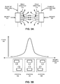
- Figure 3A is a block diagram of an embodiment of magnetic field interaction for a toggle switch that provides mechanical control magnetically.
- Magnet 302 is disposed in or on a first arm (either a fixed or a movable arm) in a toggle switch as described herein.
- Magnet 304 is disposed in a second arm (the other of the fixed or movable arm).
- Dashed lines represent the plane of a face of the first arm 322, and a plane of a face of the second arm 324. Curved lines are shown extending from each magnet to represent the magnetic fields produced by each magnet.
- the arrows represent the general direction of the magnetic fields, field direction 312 for magnet 302 and field direction 314 for magnet 304.
- a field direction is defined as the general outward direction that the lines of the magnetic field come off the face of the magnet.
- arrows are generally shown pointing from the north to the south pole.
- the lines with the arrows merely represent the general direction of the repelling force as directed from one magnet to the other.
- the magnets could be oriented with south poles facing each other or north poles facing each other.
- the magnetic field of magnet 302 is generally orthogonal to the first arm.
- the magnetic field of magnet 304 is generally orthogonal to the second arm.
- such a configuration is not necessary. While such a configuration may provide the "cleanest" toggle feel and over-center action, similar action could be achieved in a somewhat modified way by angling the magnets at non-orthogonal positions.
- the fields may still generally face each other and provide a repulsive force, thus functionally substantially the same as described herein. It will be understood by those of skill in the art that there may be practical limits to the positioned angles, as well as increased manufacturing time, cost, and/or precision required.
- Figure 3B is a block diagram of an embodiment of a force curve for a toggle switch with opposing magnets on a movable and a fixed portion of the switch. Assuming the magnetic field directions discussed with respect to Figure 3A, Figure 3B generally illustrates relative force caused by the magnetic repulsion with the different magnet positions illustrated. As generally seen, force 320 is greatest when the magnetic fields are directly orthogonal and the magnet overlap 330 is greatest, and falls off as the overlap 330 of the magnets is decreased in either direction.
- position 334 with the magnets directly overlapping is shown corresponding to the highest force 320.
- Position 334 would correspond to the sheering of the two arms of the switch when the magnets are directly aligned.
- the force generated is a repulsive force that generally follows the field direction of the magnets.
- the magnets when the magnets are fixed in the arms of the switch, it is assumed that the magnets cannot repel each other directly away from each other.
- the force is translated into a sheering force that first resists sheering of the arms across each other, and then causes the arms to sheer away from each other once the apex of the force is reached.
- the pivot point acts as a fulcrum for the sheering force, which causes the movable arm to pivot.
- Position 332 represents an approximate state of the magnets when the switch is in one of its two resting positions
- position 336 represents an approximate state of the magnets when the switch is in the other resting position. Note that some magnetic force may still be present. It is useful to bound movement of the switch via structure of the movable arm, the fixed arm, or a combination. Thus, position 332 represents one position of the switch where the magnetic force has caused movement of the movable arm, which is then bounded by the physical properties of the switch (e.g., tabs, lips or edges, dimensions, or other physical properties of the movable and/or fixed arms). When adequate force is applied to the movable arm, the state of the switch changes through position 334 to position 336, where motion is again bounded by physical properties of the switch assembly.
- the physical properties of the switch e.g., tabs, lips or edges, dimensions, or other physical properties of the movable and/or fixed arms
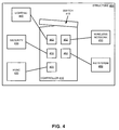
- Figure 4 is a block diagram of an embodiment of a control device with a toggle switch that controls systems within a structure.
- Structure 400 can be any building or portion of a building used for either a residence or a place of business.
- Structure 400 in general represents any space or area that has systems that can be controlled for different states of occupancy.
- Controller 410 is connected to and controls (at least to an extent) various systems in structure 400.
- Example systems are shown in Figure 4 , which are not meant to either be necessary to exhaustive as to what can be used with the system.
- Such systems may include HVAC 420, security 430, lighting 440, wireless network 450, and A/V system 460.
- Controller 410 includes a corresponding control, 422, 432, 442, 452, 462, respectively, for each system.
- a user can interact with the various systems via the controller.
- certain monitoring controls or applications on controller 410 allow a user to monitor, for example, utility use, but do not necessarily allow the user to turn the utility on or off.
- One or more control or application on controller 410 may include settings that can be changed.
- a "global" system change may be effected via switch 412, which is a switch according to any embodiment described herein. Via switch 412, settings for structure 400 may be changed, and thus structure 400 may be "turned on” and “turned off” or “awakened” and “put to sleep.”
- Figure 5 is a flow diagram of an embodiment of detecting electrical actuation of a switch via a magnet that provides mechanical actuation of the switch.
- Flow diagrams as illustrated herein provide examples of sequences of various process actions, which may be performed by processing logic that may include hardware, software, or a combination. Although shown in a particular sequence or order, unless otherwise specified, the order of the actions can be modified. Thus, the illustrated implementations should be understood only as an example, and the process can be performed in a different order, and some actions may be performed in parallel. Additionally, one or more operations can be omitted in various embodiments of the invention; thus, not all actions are required in every implementation. Other process flows are possible.
- a switch assembly includes a movable magnet that sheers across a fixed magnet. The movement of the movable magnet over the fixed magnet provides mechanical operation of the switch, and the position of the movable magnet provides electrical operation of the switch.
- a magnet position sensor detects the magnetic field, 502, specifically to determine the position of the movable magnet.
- a processor coupled to the sensor identifies a state of the magnet position sensor, 504. The state will be either off or on. It will be understood that magnet position sensors that operate based on magnetic field detection can be calibrated to be on or off depending upon a configured threshold field detected. Thus, whether the sensor state identifies an on or off state is dependent upon the calibrated threshold.
- the processor determines from the identified state what state the sensor is in, and consequently, whether the switch is considered to be on or off, 506. Magnet position sensors such as Hall effect sensors frequently operate to generate a current in the presence of sufficient magnetic field.
- the processor can be configured to recognize either the presence of the current as an "on" state for the switch or as an "off" state for the switch, depending on the implementation.
- the state identification is performed by interrupt (e.g., a change to an I/O pin is detected, which state changes based on the sensor changing states).
- State identification can be performed either by interrupt-driven mechanism or circuit-driven mechanism. An interrupt-driven mechanism detects a state of the switch, which triggers a change in a controller, which then executes an interrupt routine to handle the detected change.
- a circuit-driven mechanism causes a state change, or an output, or some other effect directly in response to the switch state change as an input to the circuit. The position could alternatively be polled, which would require more processing.
- the processor triggers one or more systems to a low power or unoccupied structure mode, 510. For example, HVAC and/or water heater settings may be adjusted, lights powered off, solar or wind power can be set to give back to the grid, security systems may be turned on, or other system triggers may occur.
- the processor if the switch state is on, 508, the processor triggers one or more system to a normal power or occupied mode, 512, which may mean to reverse the settings made in low-power mode. The system adjusts the settings based on the system mode triggered, 514, to effect the profile selected by the state of the switch.
- a machine readable storage medium may cause a machine to perform the functions or operations described, and includes any mechanism that stores information in a form accessible by a machine (e.g., computing device, electronic system, etc.), such as recordable/non-recordable media (e.g., read only memory (ROM), random access memory (RAM), magnetic disk storage media, optical storage media, flash memory devices, etc.).
- a communication interface includes any mechanism that interfaces to any of a hardwired, wireless, optical, etc., medium to communicate to another device, such as a memory bus interface, a processor bus interface, an Internet connection, a disk controller, etc.
- the communication interface can be configured by providing configuration parameters and/or sending signals to prepare the communication interface to provide a data signal describing the software content.
- the communication interface can be accessed via one or more commands or signals sent to the communication interface.
- Each component described herein may be a means for performing the operations or functions described.
- Each component described herein includes software, hardware, or a combination of these.
- the components can be implemented as software modules, hardware modules, special-purpose hardware (e.g., application specific hardware, application specific integrated circuits (ASICs), digital signal processors (DSPs), etc.), embedded controllers, hardwired circuitry, etc.
- special-purpose hardware e.g., application specific hardware, application specific integrated circuits (ASICs), digital signal processors (DSPs), etc.
- embedded controllers e.g., hardwired circuitry, etc.
Landscapes
- Switches That Are Operated By Magnetic Or Electric Fields (AREA)
- Keying Circuit Devices (AREA)
Description
- Embodiments of the invention are generally related to toggle switches, and more particularly to a master switch with mechanical and electrical control provided magnetically.
- Switches are used in a variety of consumer electronics and lighting control to provide operation by a user. Specifically within the realm of in-home displays, programmable thermostats, and home automation systems, switches can be used to provide control of home systems such as lighting, HVAC (heating, ventilation, and air conditioning), entertainment, or other systems. Switches may be electronic, such as through pushing an icon representation on a touchscreen, or mechanical such as a button, rocker switch, flip switch, or other. Known switches have separate mechanisms to provide mechanical control (e.g., springs) and electrical control. While toggle switches are known for turning on and off lights, in-home displays and programmable thermostats have traditionally used on/off buttons on the front of the unit.
-
GB2199926A -
US2009/171506A1 discloses a slide switch having two positions to indicate the occupancy status of a room wherein control of various slave components is retained by a master controller or surrendered to a room occupant. - The following description includes discussion of figures having illustrations given by way of example of implementations of embodiments of the invention. The drawings should be understood by way of example, and not by way of limitation. As used herein, references to one or more "embodiments" are to be understood as describing a particular feature, structure, or characteristic included in at least one implementation of the invention. Thus, phrases such as "in one embodiment" or "in an alternate embodiment" appearing herein describe various embodiments and implementations of the invention, and do not necessarily all refer to the same embodiment. However, they are also not necessarily mutually exclusive.
-
Figures 1A-1D are block diagrams of different aspects of an embodiment of a toggle switch where a magnet provides mechanical and electrical control in the switch. -
Figure 2 is a block diagram of an embodiment of a control device that has a toggle switch. -
Figure 3A is a block diagram of an embodiment of magnetic field interaction for a toggle switch that provides mechanical control magnetically. -
Figure 3B is a block diagram of an embodiment of a force curve for a toggle switch with opposing magnets on a movable and a fixed portion of the switch. -
Figure 4 is a block diagram of an embodiment of a control device with a toggle switch that controls systems within a structure. -
Figure 5 is a flow diagram of an embodiment of detecting electrical actuation of a switch via a magnet that provides mechanical actuation of the switch. - Descriptions of certain details and implementations follow, including a description of the figures, which may depict some or all of the embodiments described below, as well as discussing other potential embodiments or implementations of the inventive concepts presented herein. An overview of embodiments of the invention is provided below, followed by a more detailed description with reference to the drawings.
- As described herein, a switch includes magnets that provide both mechanical actuation of the switch as well as electrical operation of the switch. With such a switch, a toggle switch can be provided for a control device that results in a unique user experience for use of such devices. While toggle switches may be known for lighting control, the clean on/off toggle experience of lighting switches has not been applied to control devices such as in-home displays (IHDs), programmable thermostats, or other system controllers. A system controller equipped with such a switch can detect a state of the switch and control operation of one or more systems in a structure based on the state of the switch. The system controller can detect the state of the switch by detecting a position of a magnet of the switch.
- For such a toggle switch, a device includes a chassis or body that has a fixed portion with a first magnet. A movable portion with an opposing second magnet allows the first and second magnets to sheer across each other when the movable portion is moved. When the magnetic fields a generally directed toward each other with their fields aligned to repel each other, a force is created that must be overcome to move the movable portion. Thus, a force is applied to sheer the magnets across each other and sheer the movable portion across the face of the fixed portion.
- The magnetic field interaction provides mechanical actuation for the switch, seeing that force is applied to overcome the repulsive force of the magnetic field interaction. A magnet position sensor detects a position of the moving magnet to provide electrical actuation of the switch. Thus, one detected position of the magnet corresponds to an "ON" position of the switch triggering an on operation in the switch, and another position of the magnet corresponds to an "OFF" position of the switch triggering an off operation in the switch.
- The toggle switch incorporated into an IHD, programmable thermostat, or other control device provides an on/off toggle experience, but related to control of one or more systems of a structure. The structure can be a home (such as a single family dwelling), an apartment or other portion of a multi-family dwelling, an office building or a portion of an office building, or other structure where such control devices may be used. In one embodiment, functional operation of the switch triggers placing the structure into a "home" or "on" mode where the structure is expected to be occupied, or an "away" or "off" mode where the structure is expected to be unoccupied. The home mode may be normal settings and operation to make the system on or ready for use by an occupant, while the away mode may include low power settings intended for the structure when no occupants are present.
-
Figures 1A-1D are block diagrams of different aspects of an embodiment of a toggle switch where a magnet provides mechanical and electrical control in the switch. It will be understood that the illustrations of the drawings provide examples of certain aspects of a switch design, but are not intended to illustrate all details of the switch, nor are the drawings intended to be to scale. Certain implementation details such as rounding of corners, holes or cutouts, placement of manufacturing alignment marks, screw holes, or other such details are not illustrated for simplicity and clarity in the drawings. -
Chassis 110 illustrates a portion of a chassis or body, which provides mechanical structure for a control device.Chassis 110 includes fixed arm or fixedportion 120, which is illustrated inFigures 1A-1D as extending fromchassis 110 in a "T" shape.Magnet 122 is disposed infixed arm 120. As illustrated,magnet 122 is embedded infixed arm 120 near the end of one of the extended portions of the "T"; however, the magnet could be disposed closer to the stem of the "T". Note that forFigures 1B and 1D , the arrows forfixed arm 120 point to the stem of the "T" ofchassis 110, while inFigures 1A and 1C , the arrows point to one of the extended portions of the "T". - From the perspective of looking at
Figures 1A and 1C , movable arm ormovable portion 130 is perceived to be "behind" fixedarm 120. In one embodiment,movable arm 130 could be a portion in a plane parallel to fixedarm 120. In another embodiment, as shown inFigures 1B and 1D ,movable arm 130 may surround fixedarm 120, and the illustrations of 1A and 1C could be understood as cutaway views. As seen inFigures 1B and 1D ,movable arm 130 includes space inside of a shell, and includes a face in whichmagnet 132 is disposed. The face ofmovable arm 130 that hasmagnet 132 is parallel to fixedarm 120. -
Sensor 150 is disposed somewhere within or onchassis 110, in a place that may detect the magnetic field of magnet 132 (the movable magnet).Sensor 150 could be a Hall effect sensor or any other sensor (e.g., a reed switch) that detects, reacts to, or changes state in response to a magnetic field and generates an electrical signal in response to a magnetic field.Magnets magnets Sensor 150 detects the proximity ofmagnet 132, and generates a signal that can be detected by a processor or control logic. -
Figure 1A illustrates one position of the movable arm or the switch assembly, andFigure 1C illustrates the other position. Application of force by a user tomovable arm 130 changes the state of the switch assembly betweenFigures 1A and 1C. Figure 1B illustrates a different perspective of the switch, looking at the assembly from the side of the perspective ofFigure 1A . Similarly,Figure 1D illustrates the assembly from the side of the perspective ofFigure 1C . InFigures 1B and 1D , the plain area ofmovable arm 130 represents the face of the side of the toggle switch, and the shaded areas represent the portion of the switch that angles back away from the view ofFigures 1B and 1D . Thus, the shaded areas represent the "bottom" and "top," respectively, ofmovable arm 130 as shown inFigures 1B and 1D , which would go back into the drawing from the perspective of those figures. Additionally, certain details that would be "inside" movable arm 130 (the fixed arm and the magnets) are also shown. - It will be understood that either the position illustrated in
Figure 1A or the position illustrated inFigure 1C could be considered the "on" position, while the other would be the "off" position. The response of a system to the different positions of the switch is discussed in more detail below with respect to the other drawings. - As seen from
Figures 1A-1D , the motion ofmovable arm 130 causes a face of the movable arm to sheer across a face of fixedarm 120. Consequently, magnet 132 (the movable magnet, or the magnet in the movable arm) sheers across magnet 122 (the fixed magnet, or the magnet in the fixed arm). The magnets are aligned to pass over each other or sheer across each other with the movement ofmovable arm 130. The magnets are oriented to have repelling magnetic fields face each other. Thus, as the magnets sheer across each other, there is a force associated with the magnetic fields that causes resistance. A force must be applied tomovable arm 130 to overcome the force of the magnetic fields to move the magnets past each other. - In one embodiment, the assembly includes
pivot point 140, which may be implemented for example by attachingmovable arm 130 to fixedarm 120 with a pin or other mechanism that secures the two arms while still allowing rotation of the movable arm with respect to the fixed arm. Withpivot point 140, the sheering ofmagnet 132 acrossmagnet 122 results in an over-center operation of the switch.Pivot point 140 may be a fulcrum upon which the movable arm pivots. - It will be understood that while illustrated with a single magnet in fixed
arm 120 and a single magnet inmovable arm 130, multiple magnets could be used in either or both arms. Additionally, matching opposing magnets could be placed on the other extended portion of the "T". In such a case, multiple weaker, less expensive magnets may provide a similar effect as rare-earth magnets. It will also be understood that the faces of the arms could touch each other, or be placed in close enough proximity that there is not a measurable space or gap between the overlapping portions. Alternatively, a measurable space or gap may be created between the faces of the two arms. In general, a stronger magnetic field interaction is achieved if the arms are closer to each other, while a smoother rocking of the movable arm is achieved with at least some gap between the two. -
Figure 2 is a block diagram of an embodiment of a control device that has a toggle switch.Device 210 represents a functional diagram of a control device or other device that incorporates a switch that has both mechanical and electrical actuation via magnetic interaction. In one embodiment,device 210 is an IHD device, and certain details may be specific to such an implementation. - The examples in
Figures 1A-1D illustratedswitch 220 as a toggle switch connected to a chassis via a hinge or pivot point. In one embodiment,switch 220 provides similar operation, where ends 222 and 224 rotate up and down, opposite of each other in response to force applied to the other end. Alternatively, switch 220 could operate on a push-button operation, where the switch is pushed down and pulled back up. The operation of pushing down and pulling upswitch 220 could sheer magnets (e.g., opposing magnets in the center of the switch, or pairs at each of the ends) cross each other to provide the mechanical experience of the switch. - The electrical actuation of the switch results in a functional operation of the switch, such as the generation of a signal by a sensor, to cause something to happen responsive to a user interacting with the switch. Traditionally a programmable thermostat or an IHD are programmed and then left to run. Although they may provide information on a display, a user is generally not prompted to interact regularly with the device. With a unique user experience and an intuitive feel of turning the structure on or off, the switch in combination with
device 210 may prompt more interaction from a user. The increased interaction may result in increased awareness of the user to the functioning of systems within the premises of the structure. - In one embodiment,
switch 220 provides mechanical actuation that is connected with a main display ondevice 210. Thus, pushingswitch 220 may result in an "on" or "hello" event to activate settings associated with that event. Similarly, togglingswitch 220 to result in an "off," "goodbye," or "sleep" event may activate setting associated with the vacating of the premises. It will be understood that a profile or multiple settings can be configured fordevice 210 to control systems within the structure (e.g., lighting, HVAC (heating, ventilation, and air conditioning), entertainment, audio-visual (A/V) equipment, security system, or other systems). Togglingswitch 220 can trigger one profile or the other. In one embodiment, one profile is associated with normal operation of one or more systems in the structure, and another profile is associated with a low power mode of operation. In the low power mode, system settings may be triggered to use less energy, while returning to normal operation can reverse the low power settings. In one embodiment, although most devices may be put to lower power consumption, the security system may be triggered to come on during low power mode. -
Sensor 230 represents a magnet position sensor or a magnetic sensor to detect whetherswitch 220 is in an on or off position or state.Sensor 230 is positioned to detect or react to a magnetic field whenswitch 220 is in one state, and not detect a magnetic field or not react to or detect a weaker magnetic field whenswitch 220 is in the other state. As mentioned above, a Hall effect sensor is one type of sensor that could be used. Additionally, a reed switch has magnetic-field sensitive elements that are typically brought into contact in the presence of a sufficient magnetic field, and generates a signal. A Hall effect sensor operates on an electrical basis and is configurable to different field strength. A reed switch is principally mechanical, with portions that bend or react to a magnetic field. Any type of mechanism that reacts to a change in magnetic field state may be adequate to detect a magnetic field. As described herein, "detecting" a magnetic field refers to any form of detecting, reacting to, or changing state based on the presence or change of a magnetic field. Thus, discussion above and below regarding detecting a magnetic field will be understood to apply to detection or other types of reactions to the magnetic field. -
Controller 240 represents a processor, microcontroller, or other control logic ofdevice 210, which controls the functionality ofdevice 210 by executing logic, receiving and processing input, and generating output. In an IHD,controller 240 can provide the functionality necessary to present a display of the various functions available indevice 210, and execute each of the functions. Functions 270-1 through 270-N represent the various functions ofdevice 210. In one embodiment, each function represents and controls a different system within a structure or on a premises. Alternatively, certain functions may control multiple systems. Example systems are provided above, as well as below with respect toFigure 4 . - In one embodiment,
controller 240 detects the signal ofsensor 230, and triggers particular states of one or more systems (either individually, or collectively) in response to the detected position or state ofswitch 220.Device 210 may include a memory device (not shown) that stores settings for use with different positions ofswitch 220.Controller 240 can access the memory device and activate a particular system state of the structure (e.g., occupied or unoccupied, normal operation or low power operation) in response to the position ofswitch 220. - I/O (input/output) device(s) 250 represents one or more input and output control devices for interacting with a user. For example, buttons, switches, sliders, scroll mechanisms, displays, LEDs (light emitting diodes), or other I/O mechanisms may be used in
device 210.Switch 220 is technically an I/O device, but is represented separately. Network/system connection 260 represents connections (communicative and/or electrical) may be provided to the systems controlled bydevice 210. The devices may each have a dedicated connection, or may be connected over a bus or a network. -
Figure 3A is a block diagram of an embodiment of magnetic field interaction for a toggle switch that provides mechanical control magnetically.Magnet 302 is disposed in or on a first arm (either a fixed or a movable arm) in a toggle switch as described herein.Magnet 304 is disposed in a second arm (the other of the fixed or movable arm). Dashed lines represent the plane of a face of thefirst arm 322, and a plane of a face of thesecond arm 324. Curved lines are shown extending from each magnet to represent the magnetic fields produced by each magnet. The arrows represent the general direction of the magnetic fields,field direction 312 formagnet 302 andfield direction 314 formagnet 304. - It will be understood that magnetic fields in general curve between the north and south poles of dipole magnets. For purposes of this description, a field direction is defined as the general outward direction that the lines of the magnetic field come off the face of the magnet. It will also be understood that in magnetic field drawings, arrows are generally shown pointing from the north to the south pole. However, as shown herein, the lines with the arrows merely represent the general direction of the repelling force as directed from one magnet to the other. Thus, despite the arrows on the field lines, the magnets could be oriented with south poles facing each other or north poles facing each other.
- As illustrated, the magnetic field of
magnet 302 is generally orthogonal to the first arm. Similarly, the magnetic field ofmagnet 304 is generally orthogonal to the second arm. However, such a configuration is not necessary. While such a configuration may provide the "cleanest" toggle feel and over-center action, similar action could be achieved in a somewhat modified way by angling the magnets at non-orthogonal positions. The fields may still generally face each other and provide a repulsive force, thus functionally substantially the same as described herein. It will be understood by those of skill in the art that there may be practical limits to the positioned angles, as well as increased manufacturing time, cost, and/or precision required. - It will also be understood that the position of
magnets Figure 3A is solely for purposes of convenience in illustrating the magnetic field orientation, and is not intended to illustrate distance between the magnets for a practical system implementation. -
Figure 3B is a block diagram of an embodiment of a force curve for a toggle switch with opposing magnets on a movable and a fixed portion of the switch. Assuming the magnetic field directions discussed with respect toFigure 3A, Figure 3B generally illustrates relative force caused by the magnetic repulsion with the different magnet positions illustrated. As generally seen, force 320 is greatest when the magnetic fields are directly orthogonal and themagnet overlap 330 is greatest, and falls off as theoverlap 330 of the magnets is decreased in either direction. - Thus,
position 334 with the magnets directly overlapping is shown corresponding to thehighest force 320.Position 334 would correspond to the sheering of the two arms of the switch when the magnets are directly aligned. It will be understood that the force generated is a repulsive force that generally follows the field direction of the magnets. However, when the magnets are fixed in the arms of the switch, it is assumed that the magnets cannot repel each other directly away from each other. Thus, the force is translated into a sheering force that first resists sheering of the arms across each other, and then causes the arms to sheer away from each other once the apex of the force is reached. In an embodiment where the arms are connected via a pivot point, the pivot point acts as a fulcrum for the sheering force, which causes the movable arm to pivot. -
Position 332 represents an approximate state of the magnets when the switch is in one of its two resting positions, andposition 336 represents an approximate state of the magnets when the switch is in the other resting position. Note that some magnetic force may still be present. It is useful to bound movement of the switch via structure of the movable arm, the fixed arm, or a combination. Thus,position 332 represents one position of the switch where the magnetic force has caused movement of the movable arm, which is then bounded by the physical properties of the switch (e.g., tabs, lips or edges, dimensions, or other physical properties of the movable and/or fixed arms). When adequate force is applied to the movable arm, the state of the switch changes throughposition 334 toposition 336, where motion is again bounded by physical properties of the switch assembly. -
Figure 4 is a block diagram of an embodiment of a control device with a toggle switch that controls systems within a structure.Structure 400 can be any building or portion of a building used for either a residence or a place of business.Structure 400 in general represents any space or area that has systems that can be controlled for different states of occupancy. -
Controller 410 is connected to and controls (at least to an extent) various systems instructure 400. Example systems are shown inFigure 4 , which are not meant to either be necessary to exhaustive as to what can be used with the system. Such systems may includeHVAC 420,security 430,lighting 440,wireless network 450, and A/V system 460.Controller 410 includes a corresponding control, 422, 432, 442, 452, 462, respectively, for each system. - A user can interact with the various systems via the controller. In one embodiment, certain monitoring controls or applications on
controller 410 allow a user to monitor, for example, utility use, but do not necessarily allow the user to turn the utility on or off. One or more control or application oncontroller 410 may include settings that can be changed. A "global" system change may be effected viaswitch 412, which is a switch according to any embodiment described herein. Viaswitch 412, settings forstructure 400 may be changed, and thus structure 400 may be "turned on" and "turned off" or "awakened" and "put to sleep." -
Figure 5 is a flow diagram of an embodiment of detecting electrical actuation of a switch via a magnet that provides mechanical actuation of the switch. Flow diagrams as illustrated herein provide examples of sequences of various process actions, which may be performed by processing logic that may include hardware, software, or a combination. Although shown in a particular sequence or order, unless otherwise specified, the order of the actions can be modified. Thus, the illustrated implementations should be understood only as an example, and the process can be performed in a different order, and some actions may be performed in parallel. Additionally, one or more operations can be omitted in various embodiments of the invention; thus, not all actions are required in every implementation. Other process flows are possible. - A switch assembly includes a movable magnet that sheers across a fixed magnet. The movement of the movable magnet over the fixed magnet provides mechanical operation of the switch, and the position of the movable magnet provides electrical operation of the switch. A magnet position sensor detects the magnetic field, 502, specifically to determine the position of the movable magnet. A processor coupled to the sensor identifies a state of the magnet position sensor, 504. The state will be either off or on. It will be understood that magnet position sensors that operate based on magnetic field detection can be calibrated to be on or off depending upon a configured threshold field detected. Thus, whether the sensor state identifies an on or off state is dependent upon the calibrated threshold.
- The processor determines from the identified state what state the sensor is in, and consequently, whether the switch is considered to be on or off, 506. Magnet position sensors such as Hall effect sensors frequently operate to generate a current in the presence of sufficient magnetic field. The processor can be configured to recognize either the presence of the current as an "on" state for the switch or as an "off" state for the switch, depending on the implementation. In one embodiment, the state identification is performed by interrupt (e.g., a change to an I/O pin is detected, which state changes based on the sensor changing states). State identification can be performed either by interrupt-driven mechanism or circuit-driven mechanism. An interrupt-driven mechanism detects a state of the switch, which triggers a change in a controller, which then executes an interrupt routine to handle the detected change. A circuit-driven mechanism causes a state change, or an output, or some other effect directly in response to the switch state change as an input to the circuit. The position could alternatively be polled, which would require more processing.
- In one embodiment, if the switch state is off, 508, the processor triggers one or more systems to a low power or unoccupied structure mode, 510. For example, HVAC and/or water heater settings may be adjusted, lights powered off, solar or wind power can be set to give back to the grid, security systems may be turned on, or other system triggers may occur. In one embodiment, if the switch state is on, 508, the processor triggers one or more system to a normal power or occupied mode, 512, which may mean to reverse the settings made in low-power mode. The system adjusts the settings based on the system mode triggered, 514, to effect the profile selected by the state of the switch.
- To the extent various operations or functions are described herein, they may be described or defined as software code, instructions, configuration, and/or data. The content may be directly executable ("object" or "executable" form), source code, or difference code ("delta" or "patch" code). The software content of the embodiments described herein may be provided via an article of manufacture with the content stored thereon, or via a method of operating a communication interface to send data via the communication interface. A machine readable storage medium may cause a machine to perform the functions or operations described, and includes any mechanism that stores information in a form accessible by a machine (e.g., computing device, electronic system, etc.), such as recordable/non-recordable media (e.g., read only memory (ROM), random access memory (RAM), magnetic disk storage media, optical storage media, flash memory devices, etc.). A communication interface includes any mechanism that interfaces to any of a hardwired, wireless, optical, etc., medium to communicate to another device, such as a memory bus interface, a processor bus interface, an Internet connection, a disk controller, etc. The communication interface can be configured by providing configuration parameters and/or sending signals to prepare the communication interface to provide a data signal describing the software content. The communication interface can be accessed via one or more commands or signals sent to the communication interface.
- Various components described herein may be a means for performing the operations or functions described. Each component described herein includes software, hardware, or a combination of these. The components can be implemented as software modules, hardware modules, special-purpose hardware (e.g., application specific hardware, application specific integrated circuits (ASICs), digital signal processors (DSPs), etc.), embedded controllers, hardwired circuitry, etc.
- Besides what is described herein, various modifications may be made to the disclosed embodiments and implementations of the invention without departing from their scope. Therefore, the illustrations and examples herein should be construed in an illustrative, and not a restrictive sense. The scope of the invention should be measured solely by reference to the claims that follow.
Claims (13)
- A method comprising:identifying a state of a magnet position sensor (150), wherein the state of the magnetic position sensor is dependent upon a position of a first magnet (132) that provides mechanical actuation of a switch;wherein the first magnet is disposed in a movable arm (130) that sheers across a fixed arm (120) when moved, and wherein a second magnet (122) is disposed in the fixed arm, the first magnet having a first magnetic field that projects out from the movable arm and the second magnet having a second magnetic field that projects out from the fixed arm; and wherein the first and second magnetic fields are substantially directed toward each other and repel each other, and wherein sheering the movable arm across the fixed arm requires application of a force to the movable arm sufficient to overcome the magnetic repulsion of the first and second magnetic fields; andtriggering a system mode based on the identified state of the magnet position sensor, a first system mode activating a normal power mode corresponding to a structure being occupied and a second system mode activating a low power mode corresponding to the structure being unoccupied,wherein the mechanical actuation is an over-center movement of the movable arm, and wherein the movable arm is connected to the fixed arm at a pivot point (140).
- The method of claim 1, wherein the pivot point (140)is a fulcrum upon which the movable arm pivots.
- The method of claim 1, wherein the structure comprises a single family dwelling, a multi-family dwelling, or a work place.
- The method of claim 1, wherein activating the low power mode comprises changing operation for multiple systems selected from among: lighting, temperature control, audio-visual system, or security system; and
wherein activating the normal power mode comprises reversing the settings from the low power mode. - A toggle switch comprising:a chassis (110) having a fixed arm (120);a first magnet (132) disposed on the fixed arm, the first magnet having a first magnetic field that projects out from the fixed arm;a movable arm (130) to sheer across the fixed arm when the movable arm is moved;a second magnet (122) disposed on the movable arm, the second magnet having a second magnetic field that projects out from the movable arm;wherein the first and second magnetic fields are substantially directed toward each other and repel each other, and wherein sheering the movable arm across the fixed arm requires application of a force to the movable arm sufficient to overcome the magnetic repulsion of the first and second magnetic fields; anda magnet position sensor (150) to detect a position of the second magnet of the movable arm, wherein one position of the second magnet corresponds to an "ON" position of the switch, and another position of the second magnet corresponds to an "OFF" position of the switch,wherein the movable arm is connected to the fixed arm at a pivot point, and wherein movement of the movable arm is an over-center movement of the movable arm.
- The toggle switch of claim 5, wherein the fixed arm has a first face opposing a second face of the movable arm that sheers across the first face, and wherein the first face and the second face do not touch each other.
- The toggle switch of claim 5, wherein the first magnetic field is orthogonal to the fixed arm.
- The toggle switch of claim 5, wherein the second magnetic field is orthogonal to the movable arm.
- The toggle switch of claim 5, wherein movement of the movable arm is bounded by the pivot point, which is a fulcrum upon which the movable arm pivots.
- The toggle switch of claim 5, wherein the magnet position sensor generates a signal in response to detecting the position of the second magnet of the movable arm, the signal to trigger a system mode based on the detected position, a first system mode activating a normal power mode corresponding to a structure being occupied and a second system mode activating a low power mode corresponding to the structure being unoccupied.
- A system comprising:the toggle switch of any of claims 5 to 10; anda system controller to determine whether the switch is on or off, and trigger a system mode based on the identified state of the switch, a first system mode activating a normal power mode corresponding to a structure being occupied and a second system mode activating a low power mode corresponding to the structure being unoccupied.
- The system of claim 11, wherein the structure comprises a single family dwelling, a multi-family dwelling, or a work place.
- The system of claim 11, wherein activating the low power mode comprises changing operation for multiple systems selected from among: lighting, temperature control, audio-visual system, or security system; and
wherein activating the normal power mode comprises reversing the settings from the low power mode.
Applications Claiming Priority (2)
| Application Number | Priority Date | Filing Date | Title |
|---|---|---|---|
| US12/825,158 US8305172B2 (en) | 2010-06-28 | 2010-06-28 | Toggle switch with magnetic mechanical and electrical control |
| PCT/US2011/042001 WO2012006011A2 (en) | 2010-06-28 | 2011-06-27 | Toggle switch with magnetic mechanical and electrical control |
Publications (3)
| Publication Number | Publication Date |
|---|---|
| EP2586050A2 EP2586050A2 (en) | 2013-05-01 |
| EP2586050A4 EP2586050A4 (en) | 2014-08-06 |
| EP2586050B1 true EP2586050B1 (en) | 2016-07-20 |
Family
ID=45351991
Family Applications (1)
| Application Number | Title | Priority Date | Filing Date |
|---|---|---|---|
| EP11804080.7A Not-in-force EP2586050B1 (en) | 2010-06-28 | 2011-06-27 | Toggle switch with magnetic mechanical and electrical control |
Country Status (6)
| Country | Link |
|---|---|
| US (1) | US8305172B2 (en) |
| EP (1) | EP2586050B1 (en) |
| JP (1) | JP5621043B2 (en) |
| KR (1) | KR101530766B1 (en) |
| CN (1) | CN102959667B (en) |
| WO (1) | WO2012006011A2 (en) |
Families Citing this family (34)
| Publication number | Priority date | Publication date | Assignee | Title |
|---|---|---|---|---|
| US8335842B2 (en) | 2004-03-16 | 2012-12-18 | Icontrol Networks, Inc. | Premises management networking |
| US10339791B2 (en) | 2007-06-12 | 2019-07-02 | Icontrol Networks, Inc. | Security network integrated with premise security system |
| US11582065B2 (en) | 2007-06-12 | 2023-02-14 | Icontrol Networks, Inc. | Systems and methods for device communication |
| US8635350B2 (en) | 2006-06-12 | 2014-01-21 | Icontrol Networks, Inc. | IP device discovery systems and methods |
| US9729342B2 (en) | 2010-12-20 | 2017-08-08 | Icontrol Networks, Inc. | Defining and implementing sensor triggered response rules |
| US20150054947A1 (en) | 2005-03-16 | 2015-02-26 | Paul J. Dawes | Device for data routing in networks |
| US11218878B2 (en) | 2007-06-12 | 2022-01-04 | Icontrol Networks, Inc. | Communication protocols in integrated systems |
| US12283172B2 (en) * | 2007-06-12 | 2025-04-22 | Icontrol Networks, Inc. | Communication protocols in integrated systems |
| US12541237B2 (en) | 2007-08-10 | 2026-02-03 | Icontrol Networks, Inc. | Integrated security system with parallel processing architecture |
| US11831462B2 (en) | 2007-08-24 | 2023-11-28 | Icontrol Networks, Inc. | Controlling data routing in premises management systems |
| US11729255B2 (en) | 2008-08-11 | 2023-08-15 | Icontrol Networks, Inc. | Integrated cloud system with lightweight gateway for premises automation |
| US11758026B2 (en) | 2008-08-11 | 2023-09-12 | Icontrol Networks, Inc. | Virtual device systems and methods |
| US11258625B2 (en) | 2008-08-11 | 2022-02-22 | Icontrol Networks, Inc. | Mobile premises automation platform |
| US8638211B2 (en) | 2009-04-30 | 2014-01-28 | Icontrol Networks, Inc. | Configurable controller and interface for home SMA, phone and multimedia |
| US9729685B2 (en) | 2011-09-28 | 2017-08-08 | Apple Inc. | Cover for a tablet device |
| US8762704B2 (en) * | 2011-09-29 | 2014-06-24 | Apple Inc. | Customized content for electronic devices |
| US8847979B2 (en) * | 2012-06-08 | 2014-09-30 | Samuel G. Smith | Peek mode and graphical user interface (GUI) experience |
| KR101978239B1 (en) | 2012-06-22 | 2019-05-14 | 삼성전자주식회사 | Method for editing contents and an electronic device thereof |
| US8878637B2 (en) | 2012-08-08 | 2014-11-04 | Jared A. Sartee | Accessory device |
| CN103165296A (en) * | 2013-03-18 | 2013-06-19 | 科世达(上海)管理有限公司 | Switch |
| US9645721B2 (en) | 2013-07-19 | 2017-05-09 | Apple Inc. | Device input modes with corresponding cover configurations |
| US9474345B2 (en) | 2013-08-13 | 2016-10-25 | Apple Inc. | Magnetic related features of a cover for an electronic device |
| SG2013094115A (en) * | 2013-12-19 | 2015-07-30 | Schneider Electric South East Asia Hq Pte Ltd | Trigger actuator for a switching device |
| US11405463B2 (en) | 2014-03-03 | 2022-08-02 | Icontrol Networks, Inc. | Media content management |
| US9569943B2 (en) | 2014-12-30 | 2017-02-14 | Google Inc. | Alarm arming with open entry point |
| CN104658785B (en) * | 2015-02-13 | 2017-03-08 | 嘉兴市微能信息科技有限公司 | Libra formula magnetic pole brusque-switch equipment |
| WO2017165865A2 (en) * | 2016-03-24 | 2017-09-28 | Lutron Electronics Co., Inc | Gesture-based control device for controlling an electrical load |
| GB2560173A (en) * | 2017-03-01 | 2018-09-05 | Aqualisa Products Ltd | Controller |
| US20180335801A1 (en) * | 2017-05-19 | 2018-11-22 | Apple Inc. | Magnetically compensated button feel in an electronic system |
| US12145740B2 (en) * | 2020-11-11 | 2024-11-19 | Honeywell International Inc. | Mounting device adapter and method in a system for displaying mission critical information on an uncertified display |
| CN113294916A (en) * | 2021-05-27 | 2021-08-24 | 冉顶权 | Switch system installed on water heater outside wall |
| US12061750B1 (en) | 2023-02-08 | 2024-08-13 | Ford Global Technologies, Llc | Modular vehicle HMI |
| US12403769B2 (en) | 2023-09-21 | 2025-09-02 | Ford Global Technologies, Llc | Modular vehicle HMI |
| US12517632B2 (en) * | 2023-09-21 | 2026-01-06 | Ford Global Technologies, Llc | Modular vehicle HMI |
Family Cites Families (10)
| Publication number | Priority date | Publication date | Assignee | Title |
|---|---|---|---|---|
| SE457680B (en) * | 1987-01-15 | 1989-01-16 | Toecksfors Verkstads Ab | ELECTRONIC SWITCH INCLUDING ONE IN A MUCH MOVABLE MANUAL |
| US5348078A (en) | 1993-07-08 | 1994-09-20 | Steven D. Dushane | Dwelling heating and air conditioning system |
| JPH10134682A (en) * | 1996-10-29 | 1998-05-22 | Yazaki Corp | Non-contact switch |
| JPH1166175A (en) * | 1997-08-22 | 1999-03-09 | Hitachi Ltd | Information management system and television receiver |
| JP2002007059A (en) * | 2000-06-27 | 2002-01-11 | Nagano Fujitsu Component Kk | Device for inputting coordinates |
| US6689972B1 (en) * | 2001-09-04 | 2004-02-10 | Harrow Products, Inc. | High security switch |
| JP2003331674A (en) * | 2002-05-14 | 2003-11-21 | Konica Minolta Holdings Inc | Switch and image forming device |
| US6922123B2 (en) | 2002-11-19 | 2005-07-26 | Delphi Technologies, Inc. | Magnetic detent action for switches |
| JP2005285612A (en) | 2004-03-30 | 2005-10-13 | Hst Kk | Structure provided with magnetic reaction type sensor or switch |
| US8160749B2 (en) * | 2007-12-20 | 2012-04-17 | David Donaldson | Energy conservation system |
-
2010
- 2010-06-28 US US12/825,158 patent/US8305172B2/en not_active Expired - Fee Related
-
2011
- 2011-06-27 CN CN201180030833.7A patent/CN102959667B/en not_active Expired - Fee Related
- 2011-06-27 KR KR1020127033491A patent/KR101530766B1/en not_active Expired - Fee Related
- 2011-06-27 WO PCT/US2011/042001 patent/WO2012006011A2/en not_active Ceased
- 2011-06-27 EP EP11804080.7A patent/EP2586050B1/en not_active Not-in-force
- 2011-06-27 JP JP2013516850A patent/JP5621043B2/en not_active Expired - Fee Related
Also Published As
| Publication number | Publication date |
|---|---|
| EP2586050A4 (en) | 2014-08-06 |
| KR20130030774A (en) | 2013-03-27 |
| JP5621043B2 (en) | 2014-11-05 |
| WO2012006011A2 (en) | 2012-01-12 |
| US20110316655A1 (en) | 2011-12-29 |
| US8305172B2 (en) | 2012-11-06 |
| CN102959667B (en) | 2015-11-25 |
| CN102959667A (en) | 2013-03-06 |
| WO2012006011A3 (en) | 2012-04-12 |
| KR101530766B1 (en) | 2015-06-22 |
| EP2586050A2 (en) | 2013-05-01 |
| JP2013533589A (en) | 2013-08-22 |
Similar Documents
| Publication | Publication Date | Title |
|---|---|---|
| US8305172B2 (en) | Toggle switch with magnetic mechanical and electrical control | |
| CN109074977B (en) | Remote load control device capable of direction detection | |
| EP3427131B1 (en) | Intelligent lighting control apparatuses, systems, and methods | |
| US9520247B1 (en) | Automated operation of fixtures | |
| US9967959B2 (en) | Intelligent lighting control system learning exclusion apparatuses, systems, and methods | |
| US11715943B2 (en) | Faceplate for multi-sensor control device | |
| WO2018009716A1 (en) | Intelligent lighting control system scene list selection apparatuses, systems, and methods | |
| WO2018009758A1 (en) | Intelligent lighting control system electrical connector apparatuses, systems, and methods | |
| JP2005533357A (en) | Magnetic sensing thermostat control | |
| CN114461080A (en) | Input device and method for operating input device | |
| CN114994580A (en) | Door magnetic anomaly detection system and detection method thereof | |
| CN112065198A (en) | Anti-collision system of anti-collision door, anti-collision door and anti-collision method | |
| TW201837658A (en) | Operation device, apparatus control system | |
| KR101942522B1 (en) | An controller and a system of air conditioner comprising thereof | |
| US10389149B2 (en) | Sensory and control platform for an automation system | |
| CN112049537B (en) | Anti-collision system of anti-collision door, anti-collision door and anti-collision method | |
| CN212562899U (en) | Anticollision system and crashproof door of crashproof door | |
| US10775810B2 (en) | Control apparatus for controlling IoT devices with rotation operation | |
| RAJ | Automatic room light controller with bidirectional visitor counter | |
| CN101241807A (en) | switch system | |
| Ghuge et al. | Presence light: An intelligent lightening system for energy saving | |
| US10452145B2 (en) | Systems and methods for haptically-enhanced smart home architectures | |
| WO2016117988A1 (en) | System and device for digital automated control | |
| TW201140996A (en) | Multi-devices control module | |
| CN105718112A (en) | Display device |
Legal Events
| Date | Code | Title | Description |
|---|---|---|---|
| PUAI | Public reference made under article 153(3) epc to a published international application that has entered the european phase |
Free format text: ORIGINAL CODE: 0009012 |
|
| 17P | Request for examination filed |
Effective date: 20121207 |
|
| AK | Designated contracting states |
Kind code of ref document: A2 Designated state(s): AL AT BE BG CH CY CZ DE DK EE ES FI FR GB GR HR HU IE IS IT LI LT LU LV MC MK MT NL NO PL PT RO RS SE SI SK SM TR |
|
| DAX | Request for extension of the european patent (deleted) | ||
| A4 | Supplementary search report drawn up and despatched |
Effective date: 20140708 |
|
| RIC1 | Information provided on ipc code assigned before grant |
Ipc: H01H 3/50 20060101ALN20140702BHEP Ipc: H01H 23/16 20060101AFI20140702BHEP Ipc: H01H 5/02 20060101ALI20140702BHEP Ipc: H03K 17/97 20060101ALI20140702BHEP Ipc: G05D 23/00 20060101ALN20140702BHEP Ipc: H01H 36/00 20060101ALI20140702BHEP Ipc: H01H 23/14 20060101ALN20140702BHEP |
|
| 17Q | First examination report despatched |
Effective date: 20150320 |
|
| GRAP | Despatch of communication of intention to grant a patent |
Free format text: ORIGINAL CODE: EPIDOSNIGR1 |
|
| RIC1 | Information provided on ipc code assigned before grant |
Ipc: G05D 23/00 20060101ALN20160108BHEP Ipc: H03K 17/97 20060101ALI20160108BHEP Ipc: H01H 5/02 20060101ALI20160108BHEP Ipc: H01H 36/00 20060101ALI20160108BHEP Ipc: H01H 23/14 20060101ALN20160108BHEP Ipc: H01H 23/16 20060101AFI20160108BHEP Ipc: H01H 3/50 20060101ALN20160108BHEP |
|
| INTG | Intention to grant announced |
Effective date: 20160212 |
|
| GRAS | Grant fee paid |
Free format text: ORIGINAL CODE: EPIDOSNIGR3 |
|
| GRAA | (expected) grant |
Free format text: ORIGINAL CODE: 0009210 |
|
| AK | Designated contracting states |
Kind code of ref document: B1 Designated state(s): AL AT BE BG CH CY CZ DE DK EE ES FI FR GB GR HR HU IE IS IT LI LT LU LV MC MK MT NL NO PL PT RO RS SE SI SK SM TR |
|
| REG | Reference to a national code |
Ref country code: GB Ref legal event code: FG4D |
|
| REG | Reference to a national code |
Ref country code: CH Ref legal event code: EP |
|
| REG | Reference to a national code |
Ref country code: IE Ref legal event code: FG4D |
|
| REG | Reference to a national code |
Ref country code: AT Ref legal event code: REF Ref document number: 814671 Country of ref document: AT Kind code of ref document: T Effective date: 20160815 |
|
| REG | Reference to a national code |
Ref country code: DE Ref legal event code: R096 Ref document number: 602011028419 Country of ref document: DE |
|
| REG | Reference to a national code |
Ref country code: NL Ref legal event code: FP |
|
| REG | Reference to a national code |
Ref country code: LT Ref legal event code: MG4D |
|
| REG | Reference to a national code |
Ref country code: AT Ref legal event code: MK05 Ref document number: 814671 Country of ref document: AT Kind code of ref document: T Effective date: 20160720 |
|
| PG25 | Lapsed in a contracting state [announced via postgrant information from national office to epo] |
Ref country code: RS Free format text: LAPSE BECAUSE OF FAILURE TO SUBMIT A TRANSLATION OF THE DESCRIPTION OR TO PAY THE FEE WITHIN THE PRESCRIBED TIME-LIMIT Effective date: 20160720 Ref country code: LT Free format text: LAPSE BECAUSE OF FAILURE TO SUBMIT A TRANSLATION OF THE DESCRIPTION OR TO PAY THE FEE WITHIN THE PRESCRIBED TIME-LIMIT Effective date: 20160720 Ref country code: IT Free format text: LAPSE BECAUSE OF FAILURE TO SUBMIT A TRANSLATION OF THE DESCRIPTION OR TO PAY THE FEE WITHIN THE PRESCRIBED TIME-LIMIT Effective date: 20160720 Ref country code: IS Free format text: LAPSE BECAUSE OF FAILURE TO SUBMIT A TRANSLATION OF THE DESCRIPTION OR TO PAY THE FEE WITHIN THE PRESCRIBED TIME-LIMIT Effective date: 20161120 Ref country code: NO Free format text: LAPSE BECAUSE OF FAILURE TO SUBMIT A TRANSLATION OF THE DESCRIPTION OR TO PAY THE FEE WITHIN THE PRESCRIBED TIME-LIMIT Effective date: 20161020 Ref country code: FI Free format text: LAPSE BECAUSE OF FAILURE TO SUBMIT A TRANSLATION OF THE DESCRIPTION OR TO PAY THE FEE WITHIN THE PRESCRIBED TIME-LIMIT Effective date: 20160720 Ref country code: HR Free format text: LAPSE BECAUSE OF FAILURE TO SUBMIT A TRANSLATION OF THE DESCRIPTION OR TO PAY THE FEE WITHIN THE PRESCRIBED TIME-LIMIT Effective date: 20160720 |
|
| PG25 | Lapsed in a contracting state [announced via postgrant information from national office to epo] |
Ref country code: BE Free format text: LAPSE BECAUSE OF FAILURE TO SUBMIT A TRANSLATION OF THE DESCRIPTION OR TO PAY THE FEE WITHIN THE PRESCRIBED TIME-LIMIT Effective date: 20160720 Ref country code: SE Free format text: LAPSE BECAUSE OF FAILURE TO SUBMIT A TRANSLATION OF THE DESCRIPTION OR TO PAY THE FEE WITHIN THE PRESCRIBED TIME-LIMIT Effective date: 20160720 Ref country code: PL Free format text: LAPSE BECAUSE OF FAILURE TO SUBMIT A TRANSLATION OF THE DESCRIPTION OR TO PAY THE FEE WITHIN THE PRESCRIBED TIME-LIMIT Effective date: 20160720 Ref country code: ES Free format text: LAPSE BECAUSE OF FAILURE TO SUBMIT A TRANSLATION OF THE DESCRIPTION OR TO PAY THE FEE WITHIN THE PRESCRIBED TIME-LIMIT Effective date: 20160720 Ref country code: LV Free format text: LAPSE BECAUSE OF FAILURE TO SUBMIT A TRANSLATION OF THE DESCRIPTION OR TO PAY THE FEE WITHIN THE PRESCRIBED TIME-LIMIT Effective date: 20160720 Ref country code: PT Free format text: LAPSE BECAUSE OF FAILURE TO SUBMIT A TRANSLATION OF THE DESCRIPTION OR TO PAY THE FEE WITHIN THE PRESCRIBED TIME-LIMIT Effective date: 20161121 Ref country code: GR Free format text: LAPSE BECAUSE OF FAILURE TO SUBMIT A TRANSLATION OF THE DESCRIPTION OR TO PAY THE FEE WITHIN THE PRESCRIBED TIME-LIMIT Effective date: 20161021 Ref country code: AT Free format text: LAPSE BECAUSE OF FAILURE TO SUBMIT A TRANSLATION OF THE DESCRIPTION OR TO PAY THE FEE WITHIN THE PRESCRIBED TIME-LIMIT Effective date: 20160720 |
|
| REG | Reference to a national code |
Ref country code: DE Ref legal event code: R097 Ref document number: 602011028419 Country of ref document: DE |
|
| PG25 | Lapsed in a contracting state [announced via postgrant information from national office to epo] |
Ref country code: EE Free format text: LAPSE BECAUSE OF FAILURE TO SUBMIT A TRANSLATION OF THE DESCRIPTION OR TO PAY THE FEE WITHIN THE PRESCRIBED TIME-LIMIT Effective date: 20160720 Ref country code: RO Free format text: LAPSE BECAUSE OF FAILURE TO SUBMIT A TRANSLATION OF THE DESCRIPTION OR TO PAY THE FEE WITHIN THE PRESCRIBED TIME-LIMIT Effective date: 20160720 |
|
| PLBE | No opposition filed within time limit |
Free format text: ORIGINAL CODE: 0009261 |
|
| STAA | Information on the status of an ep patent application or granted ep patent |
Free format text: STATUS: NO OPPOSITION FILED WITHIN TIME LIMIT |
|
| PG25 | Lapsed in a contracting state [announced via postgrant information from national office to epo] |
Ref country code: DK Free format text: LAPSE BECAUSE OF FAILURE TO SUBMIT A TRANSLATION OF THE DESCRIPTION OR TO PAY THE FEE WITHIN THE PRESCRIBED TIME-LIMIT Effective date: 20160720 Ref country code: BG Free format text: LAPSE BECAUSE OF FAILURE TO SUBMIT A TRANSLATION OF THE DESCRIPTION OR TO PAY THE FEE WITHIN THE PRESCRIBED TIME-LIMIT Effective date: 20161020 Ref country code: SM Free format text: LAPSE BECAUSE OF FAILURE TO SUBMIT A TRANSLATION OF THE DESCRIPTION OR TO PAY THE FEE WITHIN THE PRESCRIBED TIME-LIMIT Effective date: 20160720 Ref country code: SK Free format text: LAPSE BECAUSE OF FAILURE TO SUBMIT A TRANSLATION OF THE DESCRIPTION OR TO PAY THE FEE WITHIN THE PRESCRIBED TIME-LIMIT Effective date: 20160720 Ref country code: CZ Free format text: LAPSE BECAUSE OF FAILURE TO SUBMIT A TRANSLATION OF THE DESCRIPTION OR TO PAY THE FEE WITHIN THE PRESCRIBED TIME-LIMIT Effective date: 20160720 |
|
| 26N | No opposition filed |
Effective date: 20170421 |
|
| PGFP | Annual fee paid to national office [announced via postgrant information from national office to epo] |
Ref country code: GB Payment date: 20170621 Year of fee payment: 7 |
|
| PG25 | Lapsed in a contracting state [announced via postgrant information from national office to epo] |
Ref country code: SI Free format text: LAPSE BECAUSE OF FAILURE TO SUBMIT A TRANSLATION OF THE DESCRIPTION OR TO PAY THE FEE WITHIN THE PRESCRIBED TIME-LIMIT Effective date: 20160720 |
|
| PGFP | Annual fee paid to national office [announced via postgrant information from national office to epo] |
Ref country code: NL Payment date: 20170614 Year of fee payment: 7 |
|
| PGFP | Annual fee paid to national office [announced via postgrant information from national office to epo] |
Ref country code: DE Payment date: 20170621 Year of fee payment: 7 |
|
| PG25 | Lapsed in a contracting state [announced via postgrant information from national office to epo] |
Ref country code: MC Free format text: LAPSE BECAUSE OF FAILURE TO SUBMIT A TRANSLATION OF THE DESCRIPTION OR TO PAY THE FEE WITHIN THE PRESCRIBED TIME-LIMIT Effective date: 20160720 |
|
| REG | Reference to a national code |
Ref country code: CH Ref legal event code: PL |
|
| REG | Reference to a national code |
Ref country code: FR Ref legal event code: ST Effective date: 20180228 |
|
| REG | Reference to a national code |
Ref country code: IE Ref legal event code: MM4A |
|
| PG25 | Lapsed in a contracting state [announced via postgrant information from national office to epo] |
Ref country code: IE Free format text: LAPSE BECAUSE OF NON-PAYMENT OF DUE FEES Effective date: 20170627 Ref country code: LI Free format text: LAPSE BECAUSE OF NON-PAYMENT OF DUE FEES Effective date: 20170630 Ref country code: LU Free format text: LAPSE BECAUSE OF NON-PAYMENT OF DUE FEES Effective date: 20170627 Ref country code: CH Free format text: LAPSE BECAUSE OF NON-PAYMENT OF DUE FEES Effective date: 20170630 |
|
| PG25 | Lapsed in a contracting state [announced via postgrant information from national office to epo] |
Ref country code: FR Free format text: LAPSE BECAUSE OF NON-PAYMENT OF DUE FEES Effective date: 20170630 |
|
| PG25 | Lapsed in a contracting state [announced via postgrant information from national office to epo] |
Ref country code: MT Free format text: LAPSE BECAUSE OF NON-PAYMENT OF DUE FEES Effective date: 20170627 |
|
| PG25 | Lapsed in a contracting state [announced via postgrant information from national office to epo] |
Ref country code: AL Free format text: LAPSE BECAUSE OF FAILURE TO SUBMIT A TRANSLATION OF THE DESCRIPTION OR TO PAY THE FEE WITHIN THE PRESCRIBED TIME-LIMIT Effective date: 20160720 |
|
| REG | Reference to a national code |
Ref country code: DE Ref legal event code: R119 Ref document number: 602011028419 Country of ref document: DE |
|
| REG | Reference to a national code |
Ref country code: NL Ref legal event code: MM Effective date: 20180701 |
|
| GBPC | Gb: european patent ceased through non-payment of renewal fee |
Effective date: 20180627 |
|
| PG25 | Lapsed in a contracting state [announced via postgrant information from national office to epo] |
Ref country code: NL Free format text: LAPSE BECAUSE OF NON-PAYMENT OF DUE FEES Effective date: 20180701 |
|
| PG25 | Lapsed in a contracting state [announced via postgrant information from national office to epo] |
Ref country code: DE Free format text: LAPSE BECAUSE OF NON-PAYMENT OF DUE FEES Effective date: 20190101 Ref country code: GB Free format text: LAPSE BECAUSE OF NON-PAYMENT OF DUE FEES Effective date: 20180627 |
|
| PG25 | Lapsed in a contracting state [announced via postgrant information from national office to epo] |
Ref country code: HU Free format text: LAPSE BECAUSE OF FAILURE TO SUBMIT A TRANSLATION OF THE DESCRIPTION OR TO PAY THE FEE WITHIN THE PRESCRIBED TIME-LIMIT; INVALID AB INITIO Effective date: 20110627 |
|
| PG25 | Lapsed in a contracting state [announced via postgrant information from national office to epo] |
Ref country code: CY Free format text: LAPSE BECAUSE OF NON-PAYMENT OF DUE FEES Effective date: 20160720 |
|
| PG25 | Lapsed in a contracting state [announced via postgrant information from national office to epo] |
Ref country code: MK Free format text: LAPSE BECAUSE OF FAILURE TO SUBMIT A TRANSLATION OF THE DESCRIPTION OR TO PAY THE FEE WITHIN THE PRESCRIBED TIME-LIMIT Effective date: 20160720 |
|
| PG25 | Lapsed in a contracting state [announced via postgrant information from national office to epo] |
Ref country code: TR Free format text: LAPSE BECAUSE OF FAILURE TO SUBMIT A TRANSLATION OF THE DESCRIPTION OR TO PAY THE FEE WITHIN THE PRESCRIBED TIME-LIMIT Effective date: 20160720 |