EP2585660B1 - Schloss und schliessvorrichtung mit einem zylinder, einem zylinderstecker und einem befestigungselement - Google Patents
Schloss und schliessvorrichtung mit einem zylinder, einem zylinderstecker und einem befestigungselement Download PDFInfo
- Publication number
- EP2585660B1 EP2585660B1 EP11798481.5A EP11798481A EP2585660B1 EP 2585660 B1 EP2585660 B1 EP 2585660B1 EP 11798481 A EP11798481 A EP 11798481A EP 2585660 B1 EP2585660 B1 EP 2585660B1
- Authority
- EP
- European Patent Office
- Prior art keywords
- cylinder
- lock device
- securing member
- cylinder plug
- flange
- Prior art date
- Legal status (The legal status is an assumption and is not a legal conclusion. Google has not performed a legal analysis and makes no representation as to the accuracy of the status listed.)
- Active
Links
Images


Classifications
-
- E—FIXED CONSTRUCTIONS
- E05—LOCKS; KEYS; WINDOW OR DOOR FITTINGS; SAFES
- E05B—LOCKS; ACCESSORIES THEREFOR; HANDCUFFS
- E05B27/00—Cylinder locks or other locks with tumbler pins or balls that are set by pushing the key in
-
- E—FIXED CONSTRUCTIONS
- E05—LOCKS; KEYS; WINDOW OR DOOR FITTINGS; SAFES
- E05B—LOCKS; ACCESSORIES THEREFOR; HANDCUFFS
- E05B9/00—Lock casings or latch-mechanism casings ; Fastening locks or fasteners or parts thereof to the wing
- E05B9/08—Fastening locks or fasteners or parts thereof, e.g. the casings of latch-bolt locks or cylinder locks to the wing
- E05B9/084—Fastening of lock cylinders, plugs or cores
- E05B9/086—Fastening of rotors, plugs or cores to an outer stator
-
- E—FIXED CONSTRUCTIONS
- E05—LOCKS; KEYS; WINDOW OR DOOR FITTINGS; SAFES
- E05B—LOCKS; ACCESSORIES THEREFOR; HANDCUFFS
- E05B27/00—Cylinder locks or other locks with tumbler pins or balls that are set by pushing the key in
- E05B27/0057—Cylinder locks or other locks with tumbler pins or balls that are set by pushing the key in with increased picking resistance
-
- E—FIXED CONSTRUCTIONS
- E05—LOCKS; KEYS; WINDOW OR DOOR FITTINGS; SAFES
- E05B—LOCKS; ACCESSORIES THEREFOR; HANDCUFFS
- E05B29/00—Cylinder locks and other locks with plate tumblers which are set by pushing the key in
-
- E—FIXED CONSTRUCTIONS
- E05—LOCKS; KEYS; WINDOW OR DOOR FITTINGS; SAFES
- E05B—LOCKS; ACCESSORIES THEREFOR; HANDCUFFS
- E05B9/00—Lock casings or latch-mechanism casings ; Fastening locks or fasteners or parts thereof to the wing
- E05B9/04—Casings of cylinder locks
-
- E—FIXED CONSTRUCTIONS
- E05—LOCKS; KEYS; WINDOW OR DOOR FITTINGS; SAFES
- E05B—LOCKS; ACCESSORIES THEREFOR; HANDCUFFS
- E05B17/00—Accessories in connection with locks
- E05B17/20—Means independent of the locking mechanism for preventing unauthorised opening, e.g. for securing the bolt in the fastening position
- E05B17/2084—Means to prevent forced opening by attack, tampering or jimmying
Definitions
- the present invention relates generally to locks and in particular to a lock device comprising a cylinder house and a cylinder plug arranged in the cylinder house.
- Locks of the abovementioned type are manoeuvred by means of a matching key, which can be inserted into a key way arranged in the cylinder plug.
- the key's action on the pins arranged in the cylinder plug and in the cylinder house releases the cylinder plug and allows the cylinder plug to be turned relative to the cylinder house.
- the cylinder house is usually mounted for use in a lock case.
- the lock case typically comprises a lock mechanism which, via mechanical coupling between the lock mechanism and the cylinder plug, permits manoeuvring of a dead bolt arranged in the lock case when the cylinder plug is turned.
- a securing member is generally arranged at the end of the cylinder plug protruding from the cylinder house.
- securing members are, for instance, a circlip received in a peripheral groove in said protruding end.
- a disadvantage of the above solution is, for example, that when an attempt is made to remove the cylinder plug mounted in the cylinder house by exerting force in the axial direction, the securing member may be radially deformed by expansion of its opening that surrounds the cylinder plug. In this way, the cylinder plug can be released from the cylinder house.
- US 4 711 106 A discloses a locking device which may be used in locking two objects together, and includes a stud having a threaded axial hole extending rearwardly from the forward end thereof and a keyed portion having at least one key, and a knob which locks over a forward portion of the stud and includes a casing with an inner surface including at least one keyway each of which receives the corresponding key on the stud to prevent rotation of the casing with respect to the stud.
- the knob also includes a tumbler housing which is mounted in an axially fixed position within the casing to rotate freely when a key is inserted into the tumbler housing, and to remain locked in a fixed position when the key is withdrawn.
- a threaded stud Connected to a rear end of the tumbler housing is a threaded stud which engages the threaded axial hole of the stud when the tumbler housing is turned by a key to thereby pull a forward portion of the stud into the casing hole.
- a first object of the present invention is to make available a lock device that improves security against manipulation of the lock device.
- Another object of the present invention is to make available a lock device that permits the use of a more reliable type of cylinder plug without structurally changing the cylinder house.
- the present invention is based on the recognition by the inventor that, instead of arranging a securing member on an end protruding from the cylinder house, the securing member can be at least partially arranged on the cylinder plug inside the cylinder house when the cylinder plug is in the mounted position.
- the interior of the cylinder house thus counteracts expansion of the securing member when a strong axial force is applied to the cylinder plug, which can occur, for example, during manipulation aimed at removing the cylinder plug from the cylinder house.
- the inventor has also recognized that, by providing the rear end of the securing member with a radially projecting flange, existing cylinder house designs do not have to be adapted to a cylinder plug and a securing member according to the invention.
- a lock device comprising:
- the cylinder house can counteract radial expansion of the securing member when a strong axial force is applied to the cylinder plug.
- the walls of the through-opening of the cylinder house can counteract radial expansion of the first portion of the securing member.
- the cylinder house does not need to be modified in order to avoid the cylinder plug being removed from the cylinder house from the front.
- the flange of the securing member bears against the outer wall of the cylinder house and is therefore not received in the through-opening.
- a function of the flange, achieved by bearing against the rear outer wall of the cylinder plug, is to prevent the cylinder plug from being able to be removed via the front of the cylinder house.
- the cylinder house does not need to be adapted to receive the securing member.
- the through-opening does not need to have a first internal diameter in order to receive the cylinder plug and a second, greater internal diameter in the portion for receiving the securing member.
- the end surface of the first end portion of the cylinder plug has a screw hole, and the lock device, in the mounted state, further comprises a screw received in the screw hole, which screw hole is arranged such that a part of the head of the screw bears against the inner peripheral surface of the flange in order to secure the flange to the cylinder plug.
- the first end portion of the cylinder plug can have a first external diameter, and a central portion of the cylinder plug can have a second external diameter, which is greater than the first external diameter.
- the design of the cylinder plug means that the cylinder house does not have to be modified in order to be able to receive said portion of the securing member.
- this can be achieved by virtue of the fact that the second external diameter can be substantially the same size as the external diameter of the first portion of the securing member.
- the first portion of the securing member can be cylindrical.
- the cylindrical shape means that the first portion can be easily turned in the through-opening.
- the cylinder plug and the securing member are secured to each other in this way, the result of which is that relative rotation between the cylinder plug and the securing member can be avoided. This reduces the risk of the securing member being unscrewed or released from the cylinder plug upon repeated rotation of the cylinder plug.
- the screw head can have a conical surface designed to bear against the inner peripheral surface of the flange.
- the conical surface can increase the contact surface between the inner peripheral surface of the flange and the screw head. The increased contact surface means that relative rotation between the cylinder plug and the securing member can be more effectively avoided.
- the inner peripheral surface of the flange can be conical in the axial direction. Upon engagement with a conical screw head, this therefore increases the resistance force against relative rotation occurring between the cylinder plug and the securing member.
- the flange can have at least one groove in the radial direction, in order to permit rotation of the securing member relative to the cylinder plug. In this way, the securing member can be easily mounted on the cylinder plug by means of a tool that engages with said at least one radial groove.
- One embodiment can further comprise a washer which, in the mounted state, is arranged between the end surface of the end portion and the screw head of the screw, in order thereby to prevent manipulation of the lock device. This therefore reduces the risk of manipulation around the rear end of the lock via the key way of the cylinder plug.
- the cylinder plug can have an integrated tailpiece.
- the manufacturing process can be simplified, and the tailpiece can have improved strength compared to a tailpiece that is mounted thereon.
- the risk of manipulation is also reduced since the integrated tailpiece means that there are no openings around the tailpiece in the rear end surface of the cylinder plug, through which openings manipulation could occur.
- the lock device according to the invention can advantageously be used together with a lock case in order thereby to form a lock.
- FIG. 1 shows a lock device 1 according to the invention.
- the lock device 1 comprises a cylinder house 3, a cylinder plug 5 (shown only schematically here by broken lines in order to illustrate that it is received in the cylinder house 3), and a securing member 9.
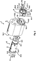
- FIG 2 shows an exploded schematic view of the lock device 1 from Figure 1 .
- the cylinder house 3 has a first plane outer wall 13-1.
- the cylinder house 3 has a second plane outer wall 13-2.
- the first outer wall 13-1 and the second outer wall 13-2 are arranged on opposite sides of the cylinder house 3.
- the first outer wall 13-1 defines a side of the cylinder house designed to receive a key.
- the second outer wall 13-2 defines a rear face of the cylinder house 3 designed to bear against a lock case.
- the cylinder house 3 has a through-opening 15.
- the cylinder plug 5 is arranged in the through-opening 15.
- the cylinder plug 5 is introduced into the through-opening 15 from the side of the cylinder house 3 that has the first outer wall 13-1, from the direction A.
- the second outer wall 13-2 has a cylindrical part 14-1 projecting axially from the second outer wall 13-2.
- the projecting part has a flange contact surface 14-2 parallel to the second outer wall 13-2.
- the cylinder plug 5 has a key way in which a key can be inserted from a direction A for the purpose of manoeuvring the cylinder plug 5.
- the cylinder plug has an end surface 6 which, when the cylinder plug 5 is in the mounted state in the cylinder house 3, projects out of the cylinder house 3.
- the end surface 6 defines an end of the cylinder plug 5 opposite the end that defines the opening of the key way.
- the cylinder plug 5 has a tailpiece 7 arranged at the end surface 6 and integrated with the cylinder plug.
- the tailpiece 7 comprises two parallel projections separated by a spacing.
- the tailpiece 7 is arranged to engage with a follower arranged in a lock case.
- the rotation force to which the cylinder plug 5 is subjected when the cylinder plug 5 is turned relative to the cylinder house 3 is transmitted mechanically by the follower to a tailpiece in a lock case.
- the tailpiece conveys the rotation force onwards for manoeuvring a dead bolt arranged in the lock case.
- the cylinder plug 5 has three portions extending in the axial direction, each with a different cross-sectional dimension.
- a first end portion 5-1 has a threaded outer peripheral surface 5'-1.
- the first end portion 5-1 has a first external diameter d1.
- the next cylinder plug portion is the central portion 5-2 of the cylinder plug 5.
- the central portion 5-2 has a group of pin openings 8, which run through the cylinder plug to the key way.
- the central portion 5-2 has a second external diameter d2, which is greater than the first external diameter d1.
- the central portion 5-2 is connected to a second end portion 5-3.
- the second end portion 5-3 is arranged on an opposite side of the central portion 5-2 from the first end portion 5-1.
- the second end portion 5-3 has an external diameter d3, which is greater than the external diameter d2 of the central portion 5-2.
- the second end portion 5-3 thus defines a cylinder-shaped flange of the cylinder plug 5.
- the through-opening 15 has an end portion with a cross-sectional dimension greater than the cross-sectional dimension d4 of the rest of the through-opening 15.
- This end portion has a cross-sectional dimension substantially the same size as the external diameter d3 of second end portion 5-3.
- the end portion is designed to receive the second end portion 5-3 of the cylinder plug 5.
- a radial surface 5'-3 of the cylinder plug 5 bears on a corresponding radial surface of the through-opening 15 where the cross-sectional dimension merges directly into the cross-sectional dimension d4.
- This design prevents the cylinder plug 5 from being able to move axially towards the rear face of the cylinder house 3 as defined by the second outer wall 13-2.
- all of said cross-sectional dimensions are diameters. Said cross-sectional dimensions are therefore circular or substantially circular.
- the securing member 9 has a cylindrical first portion 9-1 and a second portion formed by a flange 9-2.
- the flange 9-2 is cylindrical and projects radially relative to the first portion 9-1.
- a through-opening extends through the first portion 9-1 and the flange 9-2.
- the through-opening of the securing member 9 has an internal diameter substantially the same size as the external diameter d1 of the first end portion 5-1.
- the first portion 9-1 has an inner peripheral surface 9-3 which is threaded.
- the securing member 9 can therefore be arranged around the threaded first end portion 5-1 of the cylinder plug 5. In this position, the threads of the first end portion 5-1 engage with the threads in the peripheral surface 9-3.
- the first portion 9-1 of the securing member 9 has an external diameter d5 substantially the same size as the internal diameter d4 of the through-opening 15.
- the first portion 9-1 of the securing member 9 can therefore be introduced into the cylinder house 3.
- the peripheral surface of the through-opening 15 of the cylinder house 3 thus limits the radial expansion possibilities of the first portion 9-1 of the securing member 9 when acted on axially by the cylinder plug 5.
- the securing member 9 has two radial grooves 10-1 and 10-2 in the end surface of the flange 9-2. Each groove 10-1 and 10-2 runs across the entire radial extent of the end surface of the flange 9-2. In the grooves 10-1 and 10-2, tools can engage with the securing member 9 in order to allow the cylinder plug 5 and the securing member 9 to be screwed together.
- the flange has a cross-sectional dimension d6 greater than the cross-sectional dimension d4 of the through-opening 15 of the cylinder house 3.
- the end surface 6 of the cylinder plug 5 has a screw hole 11, in which a screw 19 can be screwed.
- a washer 17 can be secured to the end surface 6 by the screw 19.
- the washer 17 has two side recesses 17-1 and 17-2 designed to receive the two projections of the tailpiece 7.
- the washer 17 has a recess 17-3 for receiving the screw 19.
- the head of the screw 19 is preferably cone-shaped.
- the screw hole 11 preferably has a cone-shaped opening designed to receive a cone-shaped screw head.
- the peripheral inner surface 9-4 of the flange 9-2 converges in the axial direction towards the first outer wall 13-1. This increases the contact surface between the cone-shaped screw head and the peripheral inner surface 9-4 which, in the mounted position, bears against the cone-shaped screw head.
- the screw hole 11 is arranged near the periphery of the end surface 6 in order to ensure that the head of the screw 19 will bear against the peripheral inner surface 9-4.
- the fixing of the securing member 9 and of the cylinder plug 5 by means of the screw 19 avoids the securing member 9 and the cylinder plug 5 coming loose from each other upon repeated turning of the cylinder plug 5, for example by means of a key.
- Figure 3a shows clearly how the screw 19 bears against the peripheral inner surface 9-4 of the flange 9-2.
- Figure 3b shows a partially cutaway side view of the lock device 1.
- the figure shows the cylinder plug 5 received in the cylinder house 3.
- the securing member 9 is mounted on the cylinder plug 5. It can be seen in particular that the flange 9-2 bears against the flange contact surface 14-2. This design avoids the cylinder plug 5 being able to be removed by force from the cylinder house 3.
- the flange can have a non-circular cross section. It suffices that the flange has a cross-sectional dimension greater than the diameter d4 of the through-hole.
- the cylinder house can have a substantially plane rear outer wall, against which the flange can bear.
- the tailpiece instead of being integrated with the cylinder plug, can be mounted onto the cylinder plug.
Landscapes
- Engineering & Computer Science (AREA)
- Mechanical Engineering (AREA)
- Physics & Mathematics (AREA)
- Electromagnetism (AREA)
- Underground Structures, Protecting, Testing And Restoring Foundations (AREA)
- Mutual Connection Of Rods And Tubes (AREA)
- Filling Or Discharging Of Gas Storage Vessels (AREA)
Claims (11)
- Schließvorrichtung (1), umfassend:ein Zylindergehäuse (3) mit einer durchgehenden Öffnung (15), einem Zylinderstecker (5), der in der durchgehenden Öffnung (15) aufgenommen werden kann und dem drehbaren Eingriff in das Zylindergehäuse (3) dient, wobei der Zylinderstecker (5) einen ersten Endabschnitt (5-1) aufweist, der eine äußere periphere Oberfläche mit Gewinde umfasst, und einem Befestigungselement (9) mit einer durchgehenden Öffnung, wobei das Befestigungselement (9) einen ersten Abschnitt (9-1) aufweist, an dem die periphere Oberfläche der durchgehenden Öffnung ein Gewinde für den Eingriff mit der äußeren peripheren Oberfläche mit Gewinde des ersten Endabschnitts (5-1) aufweist, undeinem Flansch (9-2) der eine Querschnittsabmessung d6 aufweist, die größer ist, als die Querschnittsabmessung d4 der durchgehenden Öffnung (15), wobei der erste Abschnitt (9-1) des Befestigungselements (9) so aufgebaut ist, dass er in der durchgehenden Öffnung (15) des Zylindergehäuses (3) aufgenommen werden kann, wobei der Flansch (9-2) an einer Außenwand (14-2) des Zylindergehäuses (3) anliegt, wobei die Endoberfläche (6) des ersten Endabschnitts (5-1) des Zylindersteckers (5) ein Schraubenloch (11) aufweist, wobei die Schließvorrichtung (1) im montierten Zustand ferner eine Schraube (19) umfasst, die in dem Schraubenloch (11) aufgenommen wird, wobei das Schraubenloch (11) so angeordnet ist, dass ein Teil des Kopfs der Schraube (19) an der inneren peripheren Oberfläche (9-4) des Flanschs (9-2) anliegt, um den Flansch (9-2) am Zylinderstecker (5) zu sichern.
- Schließvorrichtung (1) nach Anspruch 1, wobei der erste Endabschnitt (5-1) des Zylindersteckers (5) einen ersten Außendurchmesser d1 aufweist, und ein mittiger Abschnitt (5-2) des Zylindersteckers (5) einen zweiten Außendurchmesser d2 aufweist, der größer ist, als der erste Außendurchmesser d1.
- Schließvorrichtung (1) nach Anspruch 2, wobei der zweite Außendurchmesser d2 im Wesentlichen dieselbe Größe aufweist, wie der Außendurchmesser d5 des ersten Abschnitts (9-1) des Befestigungselements (9).
- Schließvorrichtung (1) nach einem der vorhergehenden Ansprüche, wobei der erste Abschnitt (9-1) des Befestigungselements (9) zylindrisch ist.
- Schließvorrichtung (1) nach einem der vorhergehenden Ansprüche, wobei die Querschnittsabmessung d4 der durchgehenden Öffnung (15) und der Außendurchmesser d5 des ersten Abschnitts (9-1) des Befestigungselements (9) im Wesentlichen die gleiche Größe aufweisen.
- Schließvorrichtung (1) nach einem der vorhergehenden Ansprüche, wobei der Schraubenkopf eine konische Oberfläche aufweist, die vorgesehen ist, um an der inneren peripheren Oberfläche (9-4) des Flanschs anzuliegen.
- Schließvorrichtung (1) nach Anspruch 6, wobei die innere periphere Oberfläche (9-4) des Flanschs (9-2) in der axialen Richtung konisch ist.
- Schließvorrichtung (1) nach einem der vorhergehenden Ansprüche, wobei der Flansch (9-2) wenigstes eine Kerbe (10-1, 10-2) in der radialen Richtung aufweist, um eine Drehung des Befestigungselements (9) im Verhältnis zu dem Zylinderstecker (5) zu gestatten.
- Schließvorrichtung (1) nach einem der vorhergehenden Ansprüche, ferner umfassend eine Scheibe (17), die im montierten Zustand zwischen der Endoberfläche (6) des Endabschnitts (5-1) und dem Schraubenkopf der Schraube (19) angeordnet ist, um dadurch eine Manipulation der Schließvorrichtung (1) zu verhindern.
- Schließvorrichtung (1) nach einem der vorhergehenden Ansprüche, wobei der Zylinderstecker (5) ein integriertes Abschlussstück (7) aufweist.
- Schloss, umfassend eine Schließvorrichtung (1) nach einem der Ansprüche 1 bis 10 und einen Schlosskasten, wobei die Schließvorrichtung so aufgebaut ist, dass sie durch eine mechanische Koppelung in den Schlosskasten eingreift.
Priority Applications (1)
| Application Number | Priority Date | Filing Date | Title |
|---|---|---|---|
| PL11798481T PL2585660T3 (pl) | 2010-06-24 | 2011-06-23 | Zamki i urządzenia zamykające zawierające cylinder, wkładkę cylindra i element zabezpieczający |
Applications Claiming Priority (2)
| Application Number | Priority Date | Filing Date | Title |
|---|---|---|---|
| SE1050693A SE534259C2 (sv) | 2010-06-24 | 2010-06-24 | Lås och låsanordning med cylinder, cylinderkärna och fastlåsningsorgan |
| PCT/SE2011/050832 WO2011162712A1 (en) | 2010-06-24 | 2011-06-23 | Lock and lock device comprises a cylinder, cylinder plug and a securing member |
Publications (3)
| Publication Number | Publication Date |
|---|---|
| EP2585660A1 EP2585660A1 (de) | 2013-05-01 |
| EP2585660A4 EP2585660A4 (de) | 2016-07-20 |
| EP2585660B1 true EP2585660B1 (de) | 2018-07-18 |
Family
ID=44166408
Family Applications (1)
| Application Number | Title | Priority Date | Filing Date |
|---|---|---|---|
| EP11798481.5A Active EP2585660B1 (de) | 2010-06-24 | 2011-06-23 | Schloss und schliessvorrichtung mit einem zylinder, einem zylinderstecker und einem befestigungselement |
Country Status (6)
| Country | Link |
|---|---|
| EP (1) | EP2585660B1 (de) |
| DK (1) | DK2585660T3 (de) |
| LT (1) | LT2585660T (de) |
| PL (1) | PL2585660T3 (de) |
| SE (1) | SE534259C2 (de) |
| WO (1) | WO2011162712A1 (de) |
Families Citing this family (1)
| Publication number | Priority date | Publication date | Assignee | Title |
|---|---|---|---|---|
| CN104110171A (zh) * | 2014-03-13 | 2014-10-22 | 徐发煌 | 螺旋锐角间隔定位防钻防盗锁 |
Family Cites Families (5)
| Publication number | Priority date | Publication date | Assignee | Title |
|---|---|---|---|---|
| US4711106A (en) * | 1986-12-31 | 1987-12-08 | Johnson Clyde T | Locking device |
| SE510053C2 (sv) * | 1997-08-15 | 1999-04-12 | Assa Ab | Cylinderlås |
| CN2506740Y (zh) * | 2001-11-10 | 2002-08-21 | 台山华一五金制品有限公司 | 具有高抗拉强度锁芯的门锁 |
| US7290418B2 (en) * | 2004-07-30 | 2007-11-06 | Ez Change Lock Company, Llc | Programmable lock with a controlled programming position |
| ES2561977T3 (es) * | 2007-02-21 | 2016-03-01 | Assa Abloy Ab | Dispositivo de bloqueo |
-
2010
- 2010-06-24 SE SE1050693A patent/SE534259C2/sv unknown
-
2011
- 2011-06-23 LT LTEP11798481.5T patent/LT2585660T/lt unknown
- 2011-06-23 DK DK11798481.5T patent/DK2585660T3/en active
- 2011-06-23 EP EP11798481.5A patent/EP2585660B1/de active Active
- 2011-06-23 PL PL11798481T patent/PL2585660T3/pl unknown
- 2011-06-23 WO PCT/SE2011/050832 patent/WO2011162712A1/en not_active Ceased
Non-Patent Citations (1)
| Title |
|---|
| None * |
Also Published As
| Publication number | Publication date |
|---|---|
| WO2011162712A1 (en) | 2011-12-29 |
| PL2585660T3 (pl) | 2019-01-31 |
| SE1050693A1 (sv) | 2011-06-21 |
| DK2585660T3 (en) | 2018-10-29 |
| EP2585660A1 (de) | 2013-05-01 |
| EP2585660A4 (de) | 2016-07-20 |
| LT2585660T (lt) | 2018-10-10 |
| SE534259C2 (sv) | 2011-06-21 |
Similar Documents
| Publication | Publication Date | Title |
|---|---|---|
| US8707746B1 (en) | Lock with replaceable bottom pins | |
| US9103141B2 (en) | Connection means and lock mounting device with such connection means | |
| TWI647370B (zh) | 掛鎖 | |
| US2900697A (en) | Fasteners for panels and the like | |
| US20170002587A1 (en) | Lock assembly with an interchangeable lock core | |
| US9435140B2 (en) | Locking device | |
| US7895865B2 (en) | Cylinder lock assembly with a tailpiece rotationally coupled to the cylinder plug | |
| EP2585660B1 (de) | Schloss und schliessvorrichtung mit einem zylinder, einem zylinderstecker und einem befestigungselement | |
| EP3783175B1 (de) | Bausatz für nockenverschluss | |
| CN111425069B (zh) | 基于破坏后自动死锁的锁心结构 | |
| CN110618501B (zh) | 防松光纤连接器插头壳体及防松光纤连接器插头 | |
| EP2990569B1 (de) | Zylinderkern für einen zylinder für schlösser | |
| EP3470605B1 (de) | Schliessvorrichtung und schlüssel | |
| US20090001735A1 (en) | Mechanism for Securing the Handle of a Door or Window | |
| US10465417B2 (en) | Housing for removable lock core | |
| US20080083253A1 (en) | Door lock assembly with which a door cannot be unlatched by rotating a handle | |
| US20110061501A1 (en) | Signal lock tool | |
| EP2450507B1 (de) | Schlossschutz für ein Zylinderschloss | |
| CN219605078U (zh) | 矿用小绞车授权开启装置 | |
| CN219576079U (zh) | 一种连接器锁环及连接器锁环组件 | |
| EP2811087B1 (de) | Schloss mit auswechselbaren, unteren Zuhaltungen | |
| CN210714148U (zh) | 锁芯机构、锁具和解锁钥匙 | |
| JP2017008599A (ja) | シリンダー錠 | |
| KR200160554Y1 (ko) | 도어 록 조립체 | |
| CN121123722A (zh) | 解锁工具和线缆组件拔出方法 |
Legal Events
| Date | Code | Title | Description |
|---|---|---|---|
| PUAI | Public reference made under article 153(3) epc to a published international application that has entered the european phase |
Free format text: ORIGINAL CODE: 0009012 |
|
| 17P | Request for examination filed |
Effective date: 20130121 |
|
| AK | Designated contracting states |
Kind code of ref document: A1 Designated state(s): AL AT BE BG CH CY CZ DE DK EE ES FI FR GB GR HR HU IE IS IT LI LT LU LV MC MK MT NL NO PL PT RO RS SE SI SK SM TR |
|
| DAX | Request for extension of the european patent (deleted) | ||
| RA4 | Supplementary search report drawn up and despatched (corrected) |
Effective date: 20160621 |
|
| RIC1 | Information provided on ipc code assigned before grant |
Ipc: E05B 17/20 20060101ALN20160615BHEP Ipc: E05B 9/04 20060101AFI20160615BHEP Ipc: E05B 9/08 20060101ALI20160615BHEP |
|
| REG | Reference to a national code |
Ref country code: DE Ref legal event code: R079 Ref document number: 602011050204 Country of ref document: DE Free format text: PREVIOUS MAIN CLASS: E05B0027000000 Ipc: E05B0009040000 |
|
| GRAP | Despatch of communication of intention to grant a patent |
Free format text: ORIGINAL CODE: EPIDOSNIGR1 |
|
| STAA | Information on the status of an ep patent application or granted ep patent |
Free format text: STATUS: GRANT OF PATENT IS INTENDED |
|
| RIC1 | Information provided on ipc code assigned before grant |
Ipc: E05B 17/20 20060101ALN20171221BHEP Ipc: E05B 9/04 20060101AFI20171221BHEP Ipc: E05B 9/08 20060101ALI20171221BHEP |
|
| INTG | Intention to grant announced |
Effective date: 20180119 |
|
| GRAS | Grant fee paid |
Free format text: ORIGINAL CODE: EPIDOSNIGR3 |
|
| GRAA | (expected) grant |
Free format text: ORIGINAL CODE: 0009210 |
|
| STAA | Information on the status of an ep patent application or granted ep patent |
Free format text: STATUS: THE PATENT HAS BEEN GRANTED |
|
| AK | Designated contracting states |
Kind code of ref document: B1 Designated state(s): AL AT BE BG CH CY CZ DE DK EE ES FI FR GB GR HR HU IE IS IT LI LT LU LV MC MK MT NL NO PL PT RO RS SE SI SK SM TR |
|
| REG | Reference to a national code |
Ref country code: GB Ref legal event code: FG4D |
|
| REG | Reference to a national code |
Ref country code: CH Ref legal event code: EP |
|
| REG | Reference to a national code |
Ref country code: IE Ref legal event code: FG4D |
|
| REG | Reference to a national code |
Ref country code: AT Ref legal event code: REF Ref document number: 1019534 Country of ref document: AT Kind code of ref document: T Effective date: 20180815 |
|
| REG | Reference to a national code |
Ref country code: DE Ref legal event code: R096 Ref document number: 602011050204 Country of ref document: DE |
|
| REG | Reference to a national code |
Ref country code: DK Ref legal event code: T3 Effective date: 20181016 |
|
| REG | Reference to a national code |
Ref country code: NL Ref legal event code: MP Effective date: 20180718 |
|
| REG | Reference to a national code |
Ref country code: NO Ref legal event code: T2 Effective date: 20180718 |
|
| REG | Reference to a national code |
Ref country code: AT Ref legal event code: MK05 Ref document number: 1019534 Country of ref document: AT Kind code of ref document: T Effective date: 20180718 |
|
| REG | Reference to a national code |
Ref country code: EE Ref legal event code: FG4A Ref document number: E016307 Country of ref document: EE Effective date: 20181012 |
|
| PG25 | Lapsed in a contracting state [announced via postgrant information from national office to epo] |
Ref country code: NL Free format text: LAPSE BECAUSE OF FAILURE TO SUBMIT A TRANSLATION OF THE DESCRIPTION OR TO PAY THE FEE WITHIN THE PRESCRIBED TIME-LIMIT Effective date: 20180718 |
|
| PG25 | Lapsed in a contracting state [announced via postgrant information from national office to epo] |
Ref country code: RS Free format text: LAPSE BECAUSE OF FAILURE TO SUBMIT A TRANSLATION OF THE DESCRIPTION OR TO PAY THE FEE WITHIN THE PRESCRIBED TIME-LIMIT Effective date: 20180718 Ref country code: GR Free format text: LAPSE BECAUSE OF FAILURE TO SUBMIT A TRANSLATION OF THE DESCRIPTION OR TO PAY THE FEE WITHIN THE PRESCRIBED TIME-LIMIT Effective date: 20181019 Ref country code: AT Free format text: LAPSE BECAUSE OF FAILURE TO SUBMIT A TRANSLATION OF THE DESCRIPTION OR TO PAY THE FEE WITHIN THE PRESCRIBED TIME-LIMIT Effective date: 20180718 Ref country code: SE Free format text: LAPSE BECAUSE OF FAILURE TO SUBMIT A TRANSLATION OF THE DESCRIPTION OR TO PAY THE FEE WITHIN THE PRESCRIBED TIME-LIMIT Effective date: 20180718 Ref country code: BG Free format text: LAPSE BECAUSE OF FAILURE TO SUBMIT A TRANSLATION OF THE DESCRIPTION OR TO PAY THE FEE WITHIN THE PRESCRIBED TIME-LIMIT Effective date: 20181018 |
|
| PG25 | Lapsed in a contracting state [announced via postgrant information from national office to epo] |
Ref country code: AL Free format text: LAPSE BECAUSE OF FAILURE TO SUBMIT A TRANSLATION OF THE DESCRIPTION OR TO PAY THE FEE WITHIN THE PRESCRIBED TIME-LIMIT Effective date: 20180718 Ref country code: HR Free format text: LAPSE BECAUSE OF FAILURE TO SUBMIT A TRANSLATION OF THE DESCRIPTION OR TO PAY THE FEE WITHIN THE PRESCRIBED TIME-LIMIT Effective date: 20180718 |
|
| REG | Reference to a national code |
Ref country code: DE Ref legal event code: R097 Ref document number: 602011050204 Country of ref document: DE |
|
| PG25 | Lapsed in a contracting state [announced via postgrant information from national office to epo] |
Ref country code: IT Free format text: LAPSE BECAUSE OF FAILURE TO SUBMIT A TRANSLATION OF THE DESCRIPTION OR TO PAY THE FEE WITHIN THE PRESCRIBED TIME-LIMIT Effective date: 20180718 Ref country code: ES Free format text: LAPSE BECAUSE OF FAILURE TO SUBMIT A TRANSLATION OF THE DESCRIPTION OR TO PAY THE FEE WITHIN THE PRESCRIBED TIME-LIMIT Effective date: 20180718 Ref country code: CZ Free format text: LAPSE BECAUSE OF FAILURE TO SUBMIT A TRANSLATION OF THE DESCRIPTION OR TO PAY THE FEE WITHIN THE PRESCRIBED TIME-LIMIT Effective date: 20180718 Ref country code: RO Free format text: LAPSE BECAUSE OF FAILURE TO SUBMIT A TRANSLATION OF THE DESCRIPTION OR TO PAY THE FEE WITHIN THE PRESCRIBED TIME-LIMIT Effective date: 20180718 |
|
| PLBE | No opposition filed within time limit |
Free format text: ORIGINAL CODE: 0009261 |
|
| STAA | Information on the status of an ep patent application or granted ep patent |
Free format text: STATUS: NO OPPOSITION FILED WITHIN TIME LIMIT |
|
| PG25 | Lapsed in a contracting state [announced via postgrant information from national office to epo] |
Ref country code: SM Free format text: LAPSE BECAUSE OF FAILURE TO SUBMIT A TRANSLATION OF THE DESCRIPTION OR TO PAY THE FEE WITHIN THE PRESCRIBED TIME-LIMIT Effective date: 20180718 Ref country code: SK Free format text: LAPSE BECAUSE OF FAILURE TO SUBMIT A TRANSLATION OF THE DESCRIPTION OR TO PAY THE FEE WITHIN THE PRESCRIBED TIME-LIMIT Effective date: 20180718 |
|
| 26N | No opposition filed |
Effective date: 20190423 |
|
| PG25 | Lapsed in a contracting state [announced via postgrant information from national office to epo] |
Ref country code: SI Free format text: LAPSE BECAUSE OF FAILURE TO SUBMIT A TRANSLATION OF THE DESCRIPTION OR TO PAY THE FEE WITHIN THE PRESCRIBED TIME-LIMIT Effective date: 20180718 |
|
| REG | Reference to a national code |
Ref country code: DE Ref legal event code: R119 Ref document number: 602011050204 Country of ref document: DE |
|
| PG25 | Lapsed in a contracting state [announced via postgrant information from national office to epo] |
Ref country code: MC Free format text: LAPSE BECAUSE OF FAILURE TO SUBMIT A TRANSLATION OF THE DESCRIPTION OR TO PAY THE FEE WITHIN THE PRESCRIBED TIME-LIMIT Effective date: 20180718 |
|
| REG | Reference to a national code |
Ref country code: CH Ref legal event code: PL |
|
| REG | Reference to a national code |
Ref country code: BE Ref legal event code: MM Effective date: 20190630 |
|
| PG25 | Lapsed in a contracting state [announced via postgrant information from national office to epo] |
Ref country code: TR Free format text: LAPSE BECAUSE OF FAILURE TO SUBMIT A TRANSLATION OF THE DESCRIPTION OR TO PAY THE FEE WITHIN THE PRESCRIBED TIME-LIMIT Effective date: 20180718 |
|
| PG25 | Lapsed in a contracting state [announced via postgrant information from national office to epo] |
Ref country code: DE Free format text: LAPSE BECAUSE OF NON-PAYMENT OF DUE FEES Effective date: 20200101 Ref country code: IE Free format text: LAPSE BECAUSE OF NON-PAYMENT OF DUE FEES Effective date: 20190623 |
|
| PG25 | Lapsed in a contracting state [announced via postgrant information from national office to epo] |
Ref country code: LU Free format text: LAPSE BECAUSE OF NON-PAYMENT OF DUE FEES Effective date: 20190623 Ref country code: LI Free format text: LAPSE BECAUSE OF NON-PAYMENT OF DUE FEES Effective date: 20190630 Ref country code: CH Free format text: LAPSE BECAUSE OF NON-PAYMENT OF DUE FEES Effective date: 20190630 Ref country code: BE Free format text: LAPSE BECAUSE OF NON-PAYMENT OF DUE FEES Effective date: 20190630 |
|
| PG25 | Lapsed in a contracting state [announced via postgrant information from national office to epo] |
Ref country code: PT Free format text: LAPSE BECAUSE OF FAILURE TO SUBMIT A TRANSLATION OF THE DESCRIPTION OR TO PAY THE FEE WITHIN THE PRESCRIBED TIME-LIMIT Effective date: 20181118 Ref country code: FR Free format text: LAPSE BECAUSE OF NON-PAYMENT OF DUE FEES Effective date: 20190630 |
|
| REG | Reference to a national code |
Ref country code: EE Ref legal event code: HC1A Ref document number: E016307 Country of ref document: EE |
|
| PG25 | Lapsed in a contracting state [announced via postgrant information from national office to epo] |
Ref country code: CY Free format text: LAPSE BECAUSE OF FAILURE TO SUBMIT A TRANSLATION OF THE DESCRIPTION OR TO PAY THE FEE WITHIN THE PRESCRIBED TIME-LIMIT Effective date: 20180718 |
|
| PG25 | Lapsed in a contracting state [announced via postgrant information from national office to epo] |
Ref country code: MT Free format text: LAPSE BECAUSE OF FAILURE TO SUBMIT A TRANSLATION OF THE DESCRIPTION OR TO PAY THE FEE WITHIN THE PRESCRIBED TIME-LIMIT Effective date: 20180718 Ref country code: HU Free format text: LAPSE BECAUSE OF FAILURE TO SUBMIT A TRANSLATION OF THE DESCRIPTION OR TO PAY THE FEE WITHIN THE PRESCRIBED TIME-LIMIT; INVALID AB INITIO Effective date: 20110623 |
|
| PG25 | Lapsed in a contracting state [announced via postgrant information from national office to epo] |
Ref country code: MK Free format text: LAPSE BECAUSE OF FAILURE TO SUBMIT A TRANSLATION OF THE DESCRIPTION OR TO PAY THE FEE WITHIN THE PRESCRIBED TIME-LIMIT Effective date: 20180718 |
|
| PGFP | Annual fee paid to national office [announced via postgrant information from national office to epo] |
Ref country code: LT Payment date: 20220616 Year of fee payment: 12 Ref country code: EE Payment date: 20220519 Year of fee payment: 12 |
|
| PGFP | Annual fee paid to national office [announced via postgrant information from national office to epo] |
Ref country code: PL Payment date: 20220513 Year of fee payment: 12 Ref country code: LV Payment date: 20220519 Year of fee payment: 12 |
|
| PGFP | Annual fee paid to national office [announced via postgrant information from national office to epo] |
Ref country code: IS Payment date: 20220524 Year of fee payment: 12 |
|
| REG | Reference to a national code |
Ref country code: EE Ref legal event code: MM4A Ref document number: E016307 Country of ref document: EE Effective date: 20230630 |
|
| REG | Reference to a national code |
Ref country code: LT Ref legal event code: MM4D Effective date: 20230623 |
|
| PG25 | Lapsed in a contracting state [announced via postgrant information from national office to epo] |
Ref country code: LV Free format text: LAPSE BECAUSE OF NON-PAYMENT OF DUE FEES Effective date: 20230623 |
|
| PG25 | Lapsed in a contracting state [announced via postgrant information from national office to epo] |
Ref country code: LT Free format text: LAPSE BECAUSE OF NON-PAYMENT OF DUE FEES Effective date: 20230623 |
|
| PG25 | Lapsed in a contracting state [announced via postgrant information from national office to epo] |
Ref country code: EE Free format text: LAPSE BECAUSE OF NON-PAYMENT OF DUE FEES Effective date: 20230630 Ref country code: LT Free format text: LAPSE BECAUSE OF NON-PAYMENT OF DUE FEES Effective date: 20230623 |
|
| PG25 | Lapsed in a contracting state [announced via postgrant information from national office to epo] |
Ref country code: PL Free format text: LAPSE BECAUSE OF NON-PAYMENT OF DUE FEES Effective date: 20230623 |
|
| PG25 | Lapsed in a contracting state [announced via postgrant information from national office to epo] |
Ref country code: PL Free format text: LAPSE BECAUSE OF NON-PAYMENT OF DUE FEES Effective date: 20230623 |
|
| PGFP | Annual fee paid to national office [announced via postgrant information from national office to epo] |
Ref country code: FI Payment date: 20250620 Year of fee payment: 15 |
|
| PGFP | Annual fee paid to national office [announced via postgrant information from national office to epo] |
Ref country code: GB Payment date: 20250508 Year of fee payment: 15 Ref country code: DK Payment date: 20250618 Year of fee payment: 15 |
|
| PGFP | Annual fee paid to national office [announced via postgrant information from national office to epo] |
Ref country code: NO Payment date: 20250610 Year of fee payment: 15 |
|
| PG25 | Lapsed in a contracting state [announced via postgrant information from national office to epo] |
Ref country code: IS Free format text: LAPSE BECAUSE OF NON-PAYMENT OF DUE FEES Effective date: 20240104 |