EP2585272B1 - Method for controlling the heating-up of an extrusion device for producing an elastomeric semi-finished product - Google Patents
Method for controlling the heating-up of an extrusion device for producing an elastomeric semi-finished product Download PDFInfo
- Publication number
- EP2585272B1 EP2585272B1 EP11743336.7A EP11743336A EP2585272B1 EP 2585272 B1 EP2585272 B1 EP 2585272B1 EP 11743336 A EP11743336 A EP 11743336A EP 2585272 B1 EP2585272 B1 EP 2585272B1
- Authority
- EP
- European Patent Office
- Prior art keywords
- working temperature
- elastomeric material
- structural units
- temperature
- heating
- Prior art date
- Legal status (The legal status is an assumption and is not a legal conclusion. Google has not performed a legal analysis and makes no representation as to the accuracy of the status listed.)
- Active
Links
- 238000001125 extrusion Methods 0.000 title claims description 85
- 238000000034 method Methods 0.000 title claims description 65
- 239000011265 semifinished product Substances 0.000 title claims description 27
- 239000013536 elastomeric material Substances 0.000 claims description 94
- 238000010438 heat treatment Methods 0.000 claims description 69
- 230000003247 decreasing effect Effects 0.000 claims description 4
- 239000010410 layer Substances 0.000 description 8
- 238000004073 vulcanization Methods 0.000 description 7
- 238000004873 anchoring Methods 0.000 description 6
- 230000003014 reinforcing effect Effects 0.000 description 5
- 239000011324 bead Substances 0.000 description 4
- 230000008021 deposition Effects 0.000 description 3
- 238000010586 diagram Methods 0.000 description 3
- 238000004519 manufacturing process Methods 0.000 description 3
- 239000000463 material Substances 0.000 description 3
- 239000000203 mixture Substances 0.000 description 3
- 230000002787 reinforcement Effects 0.000 description 3
- 239000003431 cross linking reagent Substances 0.000 description 2
- 238000001746 injection moulding Methods 0.000 description 2
- 239000011159 matrix material Substances 0.000 description 2
- 239000004753 textile Substances 0.000 description 2
- 238000011144 upstream manufacturing Methods 0.000 description 2
- 230000004913 activation Effects 0.000 description 1
- 239000000654 additive Substances 0.000 description 1
- 230000005540 biological transmission Effects 0.000 description 1
- 230000015572 biosynthetic process Effects 0.000 description 1
- 239000007795 chemical reaction product Substances 0.000 description 1
- 239000011247 coating layer Substances 0.000 description 1
- 238000004132 cross linking Methods 0.000 description 1
- 230000000694 effects Effects 0.000 description 1
- 238000000465 moulding Methods 0.000 description 1
- 239000004014 plasticizer Substances 0.000 description 1
- 229920000642 polymer Polymers 0.000 description 1
- 239000000047 product Substances 0.000 description 1
- 230000002035 prolonged effect Effects 0.000 description 1
- 239000012763 reinforcing filler Substances 0.000 description 1
- 230000000630 rising effect Effects 0.000 description 1
- 238000007493 shaping process Methods 0.000 description 1
- 230000001360 synchronised effect Effects 0.000 description 1
Images

Classifications
-
- B—PERFORMING OPERATIONS; TRANSPORTING
- B29—WORKING OF PLASTICS; WORKING OF SUBSTANCES IN A PLASTIC STATE IN GENERAL
- B29C—SHAPING OR JOINING OF PLASTICS; SHAPING OF MATERIAL IN A PLASTIC STATE, NOT OTHERWISE PROVIDED FOR; AFTER-TREATMENT OF THE SHAPED PRODUCTS, e.g. REPAIRING
- B29C48/00—Extrusion moulding, i.e. expressing the moulding material through a die or nozzle which imparts the desired form; Apparatus therefor
- B29C48/14—Extrusion moulding, i.e. expressing the moulding material through a die or nozzle which imparts the desired form; Apparatus therefor characterised by the particular extruding conditions, e.g. in a modified atmosphere or by using vibration
-
- B—PERFORMING OPERATIONS; TRANSPORTING
- B29—WORKING OF PLASTICS; WORKING OF SUBSTANCES IN A PLASTIC STATE IN GENERAL
- B29C—SHAPING OR JOINING OF PLASTICS; SHAPING OF MATERIAL IN A PLASTIC STATE, NOT OTHERWISE PROVIDED FOR; AFTER-TREATMENT OF THE SHAPED PRODUCTS, e.g. REPAIRING
- B29C45/00—Injection moulding, i.e. forcing the required volume of moulding material through a nozzle into a closed mould; Apparatus therefor
- B29C45/17—Component parts, details or accessories; Auxiliary operations
- B29C45/72—Heating or cooling
- B29C45/74—Heating or cooling of the injection unit
-
- B—PERFORMING OPERATIONS; TRANSPORTING
- B29—WORKING OF PLASTICS; WORKING OF SUBSTANCES IN A PLASTIC STATE IN GENERAL
- B29C—SHAPING OR JOINING OF PLASTICS; SHAPING OF MATERIAL IN A PLASTIC STATE, NOT OTHERWISE PROVIDED FOR; AFTER-TREATMENT OF THE SHAPED PRODUCTS, e.g. REPAIRING
- B29C45/00—Injection moulding, i.e. forcing the required volume of moulding material through a nozzle into a closed mould; Apparatus therefor
- B29C45/17—Component parts, details or accessories; Auxiliary operations
- B29C45/76—Measuring, controlling or regulating
- B29C45/78—Measuring, controlling or regulating of temperature
-
- B—PERFORMING OPERATIONS; TRANSPORTING
- B29—WORKING OF PLASTICS; WORKING OF SUBSTANCES IN A PLASTIC STATE IN GENERAL
- B29C—SHAPING OR JOINING OF PLASTICS; SHAPING OF MATERIAL IN A PLASTIC STATE, NOT OTHERWISE PROVIDED FOR; AFTER-TREATMENT OF THE SHAPED PRODUCTS, e.g. REPAIRING
- B29C48/00—Extrusion moulding, i.e. expressing the moulding material through a die or nozzle which imparts the desired form; Apparatus therefor
- B29C48/022—Extrusion moulding, i.e. expressing the moulding material through a die or nozzle which imparts the desired form; Apparatus therefor characterised by the choice of material
-
- B—PERFORMING OPERATIONS; TRANSPORTING
- B29—WORKING OF PLASTICS; WORKING OF SUBSTANCES IN A PLASTIC STATE IN GENERAL
- B29C—SHAPING OR JOINING OF PLASTICS; SHAPING OF MATERIAL IN A PLASTIC STATE, NOT OTHERWISE PROVIDED FOR; AFTER-TREATMENT OF THE SHAPED PRODUCTS, e.g. REPAIRING
- B29C48/00—Extrusion moulding, i.e. expressing the moulding material through a die or nozzle which imparts the desired form; Apparatus therefor
- B29C48/25—Component parts, details or accessories; Auxiliary operations
- B29C48/36—Means for plasticising or homogenising the moulding material or forcing it through the nozzle or die
- B29C48/365—Means for plasticising or homogenising the moulding material or forcing it through the nozzle or die using pumps, e.g. piston pumps
- B29C48/37—Gear pumps
-
- B—PERFORMING OPERATIONS; TRANSPORTING
- B29—WORKING OF PLASTICS; WORKING OF SUBSTANCES IN A PLASTIC STATE IN GENERAL
- B29C—SHAPING OR JOINING OF PLASTICS; SHAPING OF MATERIAL IN A PLASTIC STATE, NOT OTHERWISE PROVIDED FOR; AFTER-TREATMENT OF THE SHAPED PRODUCTS, e.g. REPAIRING
- B29C48/00—Extrusion moulding, i.e. expressing the moulding material through a die or nozzle which imparts the desired form; Apparatus therefor
- B29C48/25—Component parts, details or accessories; Auxiliary operations
- B29C48/36—Means for plasticising or homogenising the moulding material or forcing it through the nozzle or die
- B29C48/395—Means for plasticising or homogenising the moulding material or forcing it through the nozzle or die using screws surrounded by a cooperating barrel, e.g. single screw extruders
-
- B—PERFORMING OPERATIONS; TRANSPORTING
- B29—WORKING OF PLASTICS; WORKING OF SUBSTANCES IN A PLASTIC STATE IN GENERAL
- B29C—SHAPING OR JOINING OF PLASTICS; SHAPING OF MATERIAL IN A PLASTIC STATE, NOT OTHERWISE PROVIDED FOR; AFTER-TREATMENT OF THE SHAPED PRODUCTS, e.g. REPAIRING
- B29C48/00—Extrusion moulding, i.e. expressing the moulding material through a die or nozzle which imparts the desired form; Apparatus therefor
- B29C48/25—Component parts, details or accessories; Auxiliary operations
- B29C48/78—Thermal treatment of the extrusion moulding material or of preformed parts or layers, e.g. by heating or cooling
- B29C48/875—Thermal treatment of the extrusion moulding material or of preformed parts or layers, e.g. by heating or cooling for achieving a non-uniform temperature distribution, e.g. using barrels having both cooling and heating zones
-
- B—PERFORMING OPERATIONS; TRANSPORTING
- B29—WORKING OF PLASTICS; WORKING OF SUBSTANCES IN A PLASTIC STATE IN GENERAL
- B29C—SHAPING OR JOINING OF PLASTICS; SHAPING OF MATERIAL IN A PLASTIC STATE, NOT OTHERWISE PROVIDED FOR; AFTER-TREATMENT OF THE SHAPED PRODUCTS, e.g. REPAIRING
- B29C48/00—Extrusion moulding, i.e. expressing the moulding material through a die or nozzle which imparts the desired form; Apparatus therefor
- B29C48/25—Component parts, details or accessories; Auxiliary operations
- B29C48/92—Measuring, controlling or regulating
-
- B—PERFORMING OPERATIONS; TRANSPORTING
- B29—WORKING OF PLASTICS; WORKING OF SUBSTANCES IN A PLASTIC STATE IN GENERAL
- B29C—SHAPING OR JOINING OF PLASTICS; SHAPING OF MATERIAL IN A PLASTIC STATE, NOT OTHERWISE PROVIDED FOR; AFTER-TREATMENT OF THE SHAPED PRODUCTS, e.g. REPAIRING
- B29C2948/00—Indexing scheme relating to extrusion moulding
- B29C2948/92—Measuring, controlling or regulating
- B29C2948/92323—Location or phase of measurement
- B29C2948/92485—Start-up, shut-down or parameter setting phase; Emergency shut-down; Material change; Test or laboratory equipment or studies
-
- B—PERFORMING OPERATIONS; TRANSPORTING
- B29—WORKING OF PLASTICS; WORKING OF SUBSTANCES IN A PLASTIC STATE IN GENERAL
- B29C—SHAPING OR JOINING OF PLASTICS; SHAPING OF MATERIAL IN A PLASTIC STATE, NOT OTHERWISE PROVIDED FOR; AFTER-TREATMENT OF THE SHAPED PRODUCTS, e.g. REPAIRING
- B29C2948/00—Indexing scheme relating to extrusion moulding
- B29C2948/92—Measuring, controlling or regulating
- B29C2948/92504—Controlled parameter
- B29C2948/92704—Temperature
-
- B—PERFORMING OPERATIONS; TRANSPORTING
- B29—WORKING OF PLASTICS; WORKING OF SUBSTANCES IN A PLASTIC STATE IN GENERAL
- B29C—SHAPING OR JOINING OF PLASTICS; SHAPING OF MATERIAL IN A PLASTIC STATE, NOT OTHERWISE PROVIDED FOR; AFTER-TREATMENT OF THE SHAPED PRODUCTS, e.g. REPAIRING
- B29C2948/00—Indexing scheme relating to extrusion moulding
- B29C2948/92—Measuring, controlling or regulating
- B29C2948/92819—Location or phase of control
- B29C2948/92857—Extrusion unit
- B29C2948/92876—Feeding, melting, plasticising or pumping zones, e.g. the melt itself
- B29C2948/92895—Barrel or housing
-
- B—PERFORMING OPERATIONS; TRANSPORTING
- B29—WORKING OF PLASTICS; WORKING OF SUBSTANCES IN A PLASTIC STATE IN GENERAL
- B29C—SHAPING OR JOINING OF PLASTICS; SHAPING OF MATERIAL IN A PLASTIC STATE, NOT OTHERWISE PROVIDED FOR; AFTER-TREATMENT OF THE SHAPED PRODUCTS, e.g. REPAIRING
- B29C2948/00—Indexing scheme relating to extrusion moulding
- B29C2948/92—Measuring, controlling or regulating
- B29C2948/92819—Location or phase of control
- B29C2948/92857—Extrusion unit
- B29C2948/92904—Die; Nozzle zone
-
- B—PERFORMING OPERATIONS; TRANSPORTING
- B29—WORKING OF PLASTICS; WORKING OF SUBSTANCES IN A PLASTIC STATE IN GENERAL
- B29C—SHAPING OR JOINING OF PLASTICS; SHAPING OF MATERIAL IN A PLASTIC STATE, NOT OTHERWISE PROVIDED FOR; AFTER-TREATMENT OF THE SHAPED PRODUCTS, e.g. REPAIRING
- B29C2948/00—Indexing scheme relating to extrusion moulding
- B29C2948/92—Measuring, controlling or regulating
- B29C2948/92819—Location or phase of control
- B29C2948/9298—Start-up, shut-down or parameter setting phase; Emergency shut-down; Material change; Test or laboratory equipment or studies
-
- B—PERFORMING OPERATIONS; TRANSPORTING
- B29—WORKING OF PLASTICS; WORKING OF SUBSTANCES IN A PLASTIC STATE IN GENERAL
- B29C—SHAPING OR JOINING OF PLASTICS; SHAPING OF MATERIAL IN A PLASTIC STATE, NOT OTHERWISE PROVIDED FOR; AFTER-TREATMENT OF THE SHAPED PRODUCTS, e.g. REPAIRING
- B29C48/00—Extrusion moulding, i.e. expressing the moulding material through a die or nozzle which imparts the desired form; Apparatus therefor
- B29C48/03—Extrusion moulding, i.e. expressing the moulding material through a die or nozzle which imparts the desired form; Apparatus therefor characterised by the shape of the extruded material at extrusion
- B29C48/07—Flat, e.g. panels
- B29C48/08—Flat, e.g. panels flexible, e.g. films
-
- B—PERFORMING OPERATIONS; TRANSPORTING
- B29—WORKING OF PLASTICS; WORKING OF SUBSTANCES IN A PLASTIC STATE IN GENERAL
- B29C—SHAPING OR JOINING OF PLASTICS; SHAPING OF MATERIAL IN A PLASTIC STATE, NOT OTHERWISE PROVIDED FOR; AFTER-TREATMENT OF THE SHAPED PRODUCTS, e.g. REPAIRING
- B29C48/00—Extrusion moulding, i.e. expressing the moulding material through a die or nozzle which imparts the desired form; Apparatus therefor
- B29C48/03—Extrusion moulding, i.e. expressing the moulding material through a die or nozzle which imparts the desired form; Apparatus therefor characterised by the shape of the extruded material at extrusion
- B29C48/09—Articles with cross-sections having partially or fully enclosed cavities, e.g. pipes or channels
-
- B—PERFORMING OPERATIONS; TRANSPORTING
- B29—WORKING OF PLASTICS; WORKING OF SUBSTANCES IN A PLASTIC STATE IN GENERAL
- B29C—SHAPING OR JOINING OF PLASTICS; SHAPING OF MATERIAL IN A PLASTIC STATE, NOT OTHERWISE PROVIDED FOR; AFTER-TREATMENT OF THE SHAPED PRODUCTS, e.g. REPAIRING
- B29C48/00—Extrusion moulding, i.e. expressing the moulding material through a die or nozzle which imparts the desired form; Apparatus therefor
- B29C48/25—Component parts, details or accessories; Auxiliary operations
- B29C48/269—Extrusion in non-steady condition, e.g. start-up or shut-down
-
- B—PERFORMING OPERATIONS; TRANSPORTING
- B29—WORKING OF PLASTICS; WORKING OF SUBSTANCES IN A PLASTIC STATE IN GENERAL
- B29C—SHAPING OR JOINING OF PLASTICS; SHAPING OF MATERIAL IN A PLASTIC STATE, NOT OTHERWISE PROVIDED FOR; AFTER-TREATMENT OF THE SHAPED PRODUCTS, e.g. REPAIRING
- B29C48/00—Extrusion moulding, i.e. expressing the moulding material through a die or nozzle which imparts the desired form; Apparatus therefor
- B29C48/25—Component parts, details or accessories; Auxiliary operations
- B29C48/36—Means for plasticising or homogenising the moulding material or forcing it through the nozzle or die
- B29C48/375—Plasticisers, homogenisers or feeders comprising two or more stages
- B29C48/387—Plasticisers, homogenisers or feeders comprising two or more stages using a screw extruder and a gear pump
-
- B—PERFORMING OPERATIONS; TRANSPORTING
- B29—WORKING OF PLASTICS; WORKING OF SUBSTANCES IN A PLASTIC STATE IN GENERAL
- B29C—SHAPING OR JOINING OF PLASTICS; SHAPING OF MATERIAL IN A PLASTIC STATE, NOT OTHERWISE PROVIDED FOR; AFTER-TREATMENT OF THE SHAPED PRODUCTS, e.g. REPAIRING
- B29C48/00—Extrusion moulding, i.e. expressing the moulding material through a die or nozzle which imparts the desired form; Apparatus therefor
- B29C48/25—Component parts, details or accessories; Auxiliary operations
- B29C48/78—Thermal treatment of the extrusion moulding material or of preformed parts or layers, e.g. by heating or cooling
- B29C48/80—Thermal treatment of the extrusion moulding material or of preformed parts or layers, e.g. by heating or cooling at the plasticising zone, e.g. by heating cylinders
- B29C48/83—Heating or cooling the cylinders
- B29C48/832—Heating
-
- B—PERFORMING OPERATIONS; TRANSPORTING
- B29—WORKING OF PLASTICS; WORKING OF SUBSTANCES IN A PLASTIC STATE IN GENERAL
- B29C—SHAPING OR JOINING OF PLASTICS; SHAPING OF MATERIAL IN A PLASTIC STATE, NOT OTHERWISE PROVIDED FOR; AFTER-TREATMENT OF THE SHAPED PRODUCTS, e.g. REPAIRING
- B29C48/00—Extrusion moulding, i.e. expressing the moulding material through a die or nozzle which imparts the desired form; Apparatus therefor
- B29C48/25—Component parts, details or accessories; Auxiliary operations
- B29C48/78—Thermal treatment of the extrusion moulding material or of preformed parts or layers, e.g. by heating or cooling
- B29C48/80—Thermal treatment of the extrusion moulding material or of preformed parts or layers, e.g. by heating or cooling at the plasticising zone, e.g. by heating cylinders
- B29C48/84—Thermal treatment of the extrusion moulding material or of preformed parts or layers, e.g. by heating or cooling at the plasticising zone, e.g. by heating cylinders by heating or cooling the feeding screws
-
- B—PERFORMING OPERATIONS; TRANSPORTING
- B29—WORKING OF PLASTICS; WORKING OF SUBSTANCES IN A PLASTIC STATE IN GENERAL
- B29C—SHAPING OR JOINING OF PLASTICS; SHAPING OF MATERIAL IN A PLASTIC STATE, NOT OTHERWISE PROVIDED FOR; AFTER-TREATMENT OF THE SHAPED PRODUCTS, e.g. REPAIRING
- B29C48/00—Extrusion moulding, i.e. expressing the moulding material through a die or nozzle which imparts the desired form; Apparatus therefor
- B29C48/25—Component parts, details or accessories; Auxiliary operations
- B29C48/78—Thermal treatment of the extrusion moulding material or of preformed parts or layers, e.g. by heating or cooling
- B29C48/86—Thermal treatment of the extrusion moulding material or of preformed parts or layers, e.g. by heating or cooling at the nozzle zone
-
- B—PERFORMING OPERATIONS; TRANSPORTING
- B29—WORKING OF PLASTICS; WORKING OF SUBSTANCES IN A PLASTIC STATE IN GENERAL
- B29D—PRODUCING PARTICULAR ARTICLES FROM PLASTICS OR FROM SUBSTANCES IN A PLASTIC STATE
- B29D30/00—Producing pneumatic or solid tyres or parts thereof
- B29D30/06—Pneumatic tyres or parts thereof (e.g. produced by casting, moulding, compression moulding, injection moulding, centrifugal casting)
- B29D30/08—Building tyres
- B29D30/10—Building tyres on round cores, i.e. the shape of the core is approximately identical with the shape of the completed tyre
- B29D30/16—Applying the layers; Guiding or stretching the layers during application
-
- B—PERFORMING OPERATIONS; TRANSPORTING
- B29—WORKING OF PLASTICS; WORKING OF SUBSTANCES IN A PLASTIC STATE IN GENERAL
- B29K—INDEXING SCHEME ASSOCIATED WITH SUBCLASSES B29B, B29C OR B29D, RELATING TO MOULDING MATERIALS OR TO MATERIALS FOR MOULDS, REINFORCEMENTS, FILLERS OR PREFORMED PARTS, e.g. INSERTS
- B29K2021/00—Use of unspecified rubbers as moulding material
- B29K2021/006—Thermosetting elastomers
-
- B—PERFORMING OPERATIONS; TRANSPORTING
- B29—WORKING OF PLASTICS; WORKING OF SUBSTANCES IN A PLASTIC STATE IN GENERAL
- B29K—INDEXING SCHEME ASSOCIATED WITH SUBCLASSES B29B, B29C OR B29D, RELATING TO MOULDING MATERIALS OR TO MATERIALS FOR MOULDS, REINFORCEMENTS, FILLERS OR PREFORMED PARTS, e.g. INSERTS
- B29K2301/00—Use of unspecified macromolecular compounds as reinforcement
- B29K2301/10—Thermosetting resins
Definitions
- the present invention relates to a method for controlling the heating of an extrusion device of a semi-finished product made of elastomeric material.
- the above-mentioned method is carried out in a process for building a component made of elastomeric material of a tyre for vehicle wheels.
- elastomeric material is used to indicate a composition comprising at least one elastomeric polymer and at least one reinforcing filler.
- such composition further comprises additives such as, for example, a cross-linking agent and/or a plasticizer. Thanks to the presence of the cross-linking agent, such material may be cross-linked by heating, so as to make the end product.
- si-finished product made of elastomeric material is used to indicate an elongated element made of elastomeric material only and having a flat shape.
- component made of elastomeric material is used to indicate any component of the tyre, or a part thereof, obtained from said semi-finished product and thus comprising elastomeric material only.
- thermal inertia of a structural unit of an extrusion device indicates the tendency of a structural unit to withstand changes in temperature; it is higher when the mass of material constituting such structural unit is greater.
- working temperature of a structural unit of the extrusion device indicates the temperature at which such structural unit is maintained during the extrusion process. This implies that at temperatures lower than the operating one, the extrusion process does not take place.
- a tyre for vehicle wheels generally comprises a carcass structure comprising at least one carcass ply formed of reinforcing cords incorporated in an elastomeric matrix.
- the carcass ply has end edges respectively engaged with annular anchoring structures.
- the latter are arranged in the areas of the tyre usually identified by the name "beads" and they are normally formed each by a substantially circumferential annular insert on which at least one filling insert is applied, in a radially outer position thereof.
- Such annular inserts are commonly identified as “bead cores” and have the task of keeping the tyre firmly fixed to the anchoring seat specifically provided in the rim of the wheel, thus preventing, in operation, the radially inner end edge of the tyre coming out from such a seat.
- an airtight coating layer made of elastomeric material, typically called liner is typically provided in a radially inner position with respect to the carcass ply/plies.
- the belt structure comprises one or more belt layers arranged radially one on top on the other and having textile or metallic reinforcement cords arranged preferably according to an inclined orientation with respect to the circumferential direction of the tyre and normally crossed with respect to the cords of the possible adjacent belt layer.
- the belt structure can further comprise at least one reinforcing structure defined by at least one continuous reinforcing elongated element including at least one textile or metallic reinforcement cord incorporated in a matrix of elastomeric material and extending parallel to the longitudinal direction of the elongated element itself.
- under-belt a layer of elastomeric material, called "under-belt"
- under-belt a layer of elastomeric material, called "under-belt”
- said layer having the function of making the radially outer surface of the carcass structure as uniform as possible for the subsequent application of the belt structure.
- tread band In a radially outer position with respect to the belt structure a tread band is applied, also made of elastomeric material, as well as other structural elements making up the tyre.
- Respective sidewalls of elastomeric material are also applied on the side surfaces of the carcass structure, each extending from one of the side edges of the tread band up to the respective annular anchoring structure to the beads.
- a tyre for vehicle wheels typically comprises a plurality of components made of elastomeric material only, according to the definition given above.
- the following components can be identified, as non-limiting examples: tread band, sidewalls, the so-called under-belt and/or under-layer layers, filling inserts of the annular anchoring structures, liner, sub-liner, sidewall inserts, reinforcing inserts, etc.
- the above-mentioned components may be made starting from semi-finished products made of elastomeric material only, obtained by an extrusion process.
- the extruded semi-finished product is then laid on a forming support which can rotate about a rotation axis, so as to obtain a deposition preferably according to adjacent and/or at least partly superimposed coils, depending on the component to be made.
- the extrusion process is carried out in a device consisting of a plurality of structural units having different mass, thermal inertia and working temperature, where at least some structural units having low mass and thermal inertia have a high working temperature and vice versa.
- US 2003/047828A1 describes that heat-up characteristic are obtained individually for a plurality of heat zones of an injection molding machine.
- a heat-up time is obtained from the heat-up characteristic of each heat zone and the difference between a preset temperature and an actual temperature.
- a heat-zone that requires the logest heat-up time is specified. Heat-up of each heat zone is controlled in accordance with the longest heat-up time.
- JP 1 267022A describes a method of automatically raising temperatures for a multi-zone temperature control system such as an extruder, wherein separate starting times of temperature raising of the respective zones are calculated and stored the in order to make the temperatures of all the zones simultaneously arrive at the set temperature.
- JP 2002-361705A describes an injection molding machine configured so that the temperature rising completion for all of regions to be heated always coincide with each other.
- JP 2 309408A describes an automatic temperature-elevation control system wherein the slowest objective temperature arrival time and the objective temperature are divided into plural steps and a new objective temperature is found out every lapse of time in each step.
- WO 2006/037369 in the name of the Applicant, recites that in a process for manufacturing an elastomeric tyre component, the elastomeric component is fed to an extruding device comprising a plurality of units each having a respective working temperature. Said units are heated to reach the respective working temperature, starting from the unit having the lowest working temperature up to the unit having the highest working temperature.
- the Applicant has considered that, in order to ensure that during the extrusion process the elastomeric material fed into the extrusion device has sufficient fluidity at the required operating flow rates and pressures, all of the above units must be heated to reaching the respective working temperature prior to the feeding of the elastomeric material into the extrusion device.
- the Applicant has further considered that in order to minimise the process times, said heating should occur as a whole in the shortest possible time.
- the Applicant has considered that whenever the extrusion process is ended or interrupted, it is advantageous to leave some elastomeric material into the extrusion device to prevent the formation of air bubbles, which would cause troubles upon restart.
- the Applicant has noted that a method suitable for allowing the respective working temperature to be reached by all the units making up the extrusion device as quickly as possible, without risking a vulcanization of the elastomeric material at any one of the above units and without the need of running experimental tests beforehand on the single units of the specific extrusion device used would meet even better the opposed process requirements.
- the Applicant has understood that in order to limit the heating process cycle time as much as possible it is suitable to implement an automatic procedure that initially provides for the simultaneous heating of all the units, thus carrying out a method totally different from that described in WO 2006/037369 , which instead provides for a predetermined sequence of activation of the heating starting from the unit having the lowest working temperature up to that having the highest working temperature.
- the Applicant has further understood that in order to prevent the risk of having a vulcanization of the elastomeric material into the extrusion device, it is advisable that the above heating procedure be such as to allow the units having a low thermal inertia and a high working temperature to be the last ones reaching the respective working temperatures, that is, once the units having higher thermal mass and lower working temperature have reached their working temperatures.
- the Applicant has perceived that such result may be effectively obtained by implementing a heating procedure that at first provides for a simultaneous heating of all the units up to a predetermined temperature value and when a predetermined unit is close to or has reached such temperature, a further simultaneous heating of the other units up to a new temperature value properly predetermined. Such further simultaneous heating is repeated several times and each time only for the units that have not yet reached the respective working temperature, such repetition continuing until all the units of the extrusion device have reached the respective working temperature.
- the present invention therefore relates to a method for controlling the heating of an extrusion device of a semi-finished product made from elastomeric material, the extrusion device comprising a plurality of structural units, each structural unit having a working temperature different to the working temperature of at least one other structural unit and a thermal inertia different to the thermal inertia of at least one other structural unit, the method comprising:
- the Applicant believes that with the method of the present invention, when a structural unit reaches its working temperature, also the other structural units that have a lower working temperature have substantially already reached such temperature.
- this reduces the time interval required for each structural unit to reach the respective working temperature, with an advantageous reduction of the overall implementation time of the extrusion process.
- the risk of having a vulcanization of the elastomeric material at a structural unit having low thermal inertia and high working temperature is prevented. In fact, such working temperature is reached lastly and although the heating of said structural unit is relatively fast due to the low thermal inertia, the residence time at the high working temperature before starting the feeding of the elastomeric material is reduced to the minimum.
- the method of the present invention can advantageously be implemented on any extrusion device, preferably those with a gear pump, where mixture is always present at the end portion of the machine which may be removed only by disassembling parts of the machinery (the extruders with opening head and without gear pump usually allow the machine to be fully emptied, thus the cross-linking problem does not occur), irrespective of the number and type of structural units that make up such extrusion device and irrespective of the difference of mass and/or thermal inertia of said structural units. In fact, in order to implement said method it is sufficient to know only the working temperature of each structural unit making up the extrusion device.
- the present invention may have at least one of the following preferred features, taken individually or in combination with the others.
- said iterative repetition comprises at least: e) simultaneously heating said other structural units of said extrusion device.
- said iterative repetition also comprises at least:
- said iterative repetition also comprises at least:
- each structural unit has a working temperature different to the working temperature of all the other structural units.
- each structural unit has a thermal inertia different to the thermal inertia of all the other structural units.
- said plurality of structural units comprises at least one housing, at least one member for moving the elastomeric material inside said at least one housing and at least one drawing member of the elastomeric material.
- said at least one member for moving the elastomeric material comprises an extrusion screw.
- Such particular moving member has a relatively low working temperature and a predetermined thermal inertia.
- said at least one housing has a working temperature higher than that of the member for moving the elastomeric material.
- said at least one housing has a thermal inertia higher than that of the member for moving the elastomeric material.
- said at least one drawing member comprises at least one nozzle.
- Such particular drawing member is characterised in that it has a particularly low thermal inertia and a particularly high working temperature. Therefore, it is a highly critical element as regards the risk of vulcanization discussed above.
- the method of the present invention is particularly advantageous since it provides that reaching the working temperature of the nozzle occurs once all the other structural units of the extrusion device have reached their working temperature, thus reducing to the minimum the residence time of the nozzle at such high working temperature before the extrusion process for manufacturing the semi-finished product made of elastomeric material takes place.
- said at least one drawing member comprises at least one pair of calender rollers.
- said plurality of structural units further comprises at least one gear pump assembly arranged between said at least one member for moving the elastomeric material and said at least one drawing member of the elastomeric material.
- Such pump assembly preferably has a thermal inertia lower than that of the member for moving the elastomeric material and higher than that of the drawing member of the elastomeric material, especially when a nozzle is used as drawing member.
- said at least one housing has a working temperature not lower than about 50°C, more preferably not lower than about 60°C.
- said at least one housing has a working temperature not higher than about 120°C, more preferably not lower than about 90°C.
- said at least one housing has a working temperature comprised between about 50°C and about 120°C, more preferably between about 50°C and about 90°C, even more preferably between about 60°C and 90°C, even more preferably equal to about 80°C.
- said at least one member for moving the elastomeric material has a working temperature not lower than about 40°C, more preferably not lower than about 50°C.
- said at least one member for moving the elastomeric material has a working temperature not higher than about 120°C, more preferably not higher than about 90°C.
- said at least one member for moving the elastomeric material has a working temperature comprised between about 40°C and about 120°C, more preferably between about 50°C and about 90°C, even more preferably equal to about 80°C.
- said at least one drawing member has a working temperature not lower than about 70°C, more preferably not lower than about 90°C.
- said at least one drawing member has a working temperature not higher than about 130°C, more preferably not higher than about 125°C.
- said at least one drawing member has a working temperature comprised between about 70°C and about 130°C, more preferably between about 90°C and about 125°C, even more preferably equal to about 110°C.
- said at least one gear pump assembly has a working temperature not lower than about 70°C, more preferably not lower than about 80°C.
- said at least one gear pump assembly has a working temperature not higher than about 120°C, more preferably not higher than about 110°C.
- said at least one pump assembly has a working temperature comprised between about 70°C and about 120°C, more preferably between about 80°C and about 110°C, even more preferably equal to about 110°C.
- the working temperatures of said structural units are such as to define a set of increasing temperatures in the following order: member for moving the elastomeric material, housing, drawing member of the elastomeric material.
- the working temperatures of said structural units are such as to define a set of increasing temperatures in the following order: member for moving the elastomeric material, housing, gear pump assembly and drawing member of the elastomeric material.
- the thermal inertias of said structural units are such as to define a set of decreasing thermal inertias in the following order: housing, member for moving the elastomeric material, drawing member of the elastomeric material.
- the thermal inertias of said structural units are such as to define a set of decreasing thermal inertias in the following order: housing, member for moving the elastomeric material, gear pump assembly and drawing member of the elastomeric material.
- said semi-finished product made of elastomeric material has, in the output section of said drawing member, a thickness not smaller than about 0.5 mm, preferably not smaller than about 0.6 mm.
- said semi-finished product made of elastomeric material has, in the output section of said drawing member, a thickness not greater than about 4 mm, preferably not greater than about 2 mm.
- said semi-finished product made of elastomeric material has, in the output section of said drawing member, a thickness comprised between about 0.5 mm and about 4 mm, more preferably between about 0.6 mm and about 2 mm.
- said semi-finished product made of elastomeric material has, in the output section of said drawing member, a width comprised between about 5 mm and about 25 mm.
- the elastomeric material is fed into the extrusion device with a flow rate comprised between about 2 cm 3 /s and about 50 cm 3 /s.
- a flow rate comprised between about 2 cm 3 /s and about 50 cm 3 /s.
- flow rate values allow limiting the overall cycle time.
- the heating of the extrusion device is automatically controlled through a remote control unit that also manages the subsequent extrusion of the elastomeric material (when all the structural units of the extrusion device have reached the respective working temperature) for manufacturing the semi-finished product made of elastomeric material.
- the present invention has a preferred embodiment thereof in a process for building a component made of elastomeric material of a tyre for vehicle wheels.
- the above-mentioned process is preferably carried out by providing the movement of a first forming support along a first building line for building a carcass structure comprising at least one carcass ply and a pair of annular anchoring structures, and the movement of a second forming support along a second building line for building a crown structure comprising at least one belt structure and a tread band.
- the carcass structure and the crown structure thus built are transferred, with a synchronised movement in production-frequency and by respective robot arms, to a workstation for assembling and shaping the tyre being processed, where the carcass structure and the crown structure are reciprocally associated so as to obtain a green tyre.
- Such green tyre is then transferred on a moulding and curing line for obtaining the finished product.
- the process for building a component made from elastomeric material of a tyre for vehicle wheels may be carried out in a process for building a tyre wherein the single tyre components are directly built, according to a predetermined frequency, on a single forming support, generally toroidal.
- the components made of elastomeric material only are obtained starting from a semi-finished product made of elastomeric material only.
- Such semi-finished product is obtained by extrusion and is laid on a forming support while the latter is moved around a rotation axis thereof, so as to obtain a deposition preferably according to adjacent and/or at least partly superimposed coils, according to the component to be made.
- the extrusion of the semi-finished product takes place at an extrusion device 1 of the type illustrated in figure 1 .
- the semi-finished product obtained through such extrusion device is indicated with 100, whereas the forming support whereon such semi-finished product 100 is laid is indicated with 50.
- the extrusion device 1 preferably comprises four different structural units, each preferably having mass, thermal inertia (Ii) and working temperature (Ti) different from those of the other structural units.
- a first structural unit 10 of the extrusion device 10 is defined by a housing 11 in turn defined by a hollow body having a longitudinal axis X-X.
- the housing 11 comprises, at an upstream end portion 11a thereof, a hopper 12 for loading the elastomeric material to be extruded.
- a second structural unit 20 of the extrusion device 10 is defined by an extrusion screw 21 rotatably mounted within the housing 11.
- the extrusion screw 21 acts as a member for moving the elastomeric material within the housing 11.
- the extrusion screw 21 moves the elastomeric material from the upstream end portion 11a of housing 11 to a downstream end portion 11b of housing 11, along a movement direction generally indicated with A.
- a third structural unit 30 of the extrusion device 10 is preferably defined by a gear pump assembly 31 operatively associated with the housing 11 at the downstream end portion 11b thereof.
- Such gear pump assembly 31 receives the elastomeric material carried by the extrusion screw 21 and pushes it by pressure downstream, with reference to the moving direction A of the elastomeric material.
- a fourth structural unit 40 of the extrusion device 10 is preferably defined by a nozzle 41 associated with the gear pump assembly 31 downstream thereof, always with reference to the moving direction A of the elastomeric material. Through such nozzle 41, the elastomeric material pushed by the gear pump assembly 31 is drawn as a semi-finished product 100, to be then laid on the outer surface 50a of the forming support 50.
- the gear pump assembly 31 pushes the elastomeric material into the nozzle 41 with a pressure not lower than about 30 bar, preferably comprised between about 40 bar and about 600 bar.
- the elastomeric material is fed towards the forming support 50 with a flow rate preferably not lower than about 2 cm 3 /s, more preferably comprised between about 3 cm 3 /s and about 50 cm 3 /s.
- Nozzle 41 has an output opening for the elastomeric material shaped so as to define a semi-finished product 100 made of elastomeric material having desired shape and dimensions.
- the semi-finished product 100 made of elastomeric material is defined by a flat element having, in the output section of said drawing member, a thickness not smaller than about 0.5 mm, preferably not smaller than about 0.6 m, more preferably comprised between about 0.5 mm and about 3 mm, even more preferably comprised between about 0.6 mm and about 2 mm.
- Said flat element further has, in the output section of said drawing member, a width preferably comprised between about 5 mm and about 25 mm.
- the working temperatures of said structural units 11, 21, 31, 41 preferably define a set of working temperatures T i that increase in the following order: extrusion screw 21 (working temperature T 1 ), housing 11 (working temperature T 2 ), gear pump assembly 31 (working temperature T 3 ) and nozzle 41 (working temperature T 4 ).
- thermal inertias of said structural units 11, 21, 31, 41 define a set of thermal inertias I i that decrease in the following order: housing 11 (thermal inertia I 1 ) , extrusion screw 21 (thermal inertia I 2 ), gear pump assembly 31 (thermal inertia I 3 ) and nozzle 41 (thermal inertia I 4 ).
- the housing 11 has a working temperature (T 2 ) comprised between about 50°C and about 120°C, more preferably between about 50°C and about 90°C, even more preferably between about 60°C and 90°C, even more preferably equal to about 80°C.
- T 2 working temperature
- the extrusion screw 21 has a working temperature (T 1 ) comprised between about 40°C and about 120°C, more preferably between about 50°C and about 90°C, even more preferably equal to about 80°C.
- T 1 working temperature
- the nozzle 41 has a working temperature (T 4 ) comprised between about 70°C and about 130°C, more preferably between about 90°C and about 125°C, even more preferably equal to about 110°C.
- T 4 working temperature
- the gear pump assembly 31 has a working temperature (T 3 ) comprised between about 70°C and about 120°C, more preferably between about 80°C and about 110°C, even more preferably equal to about 100°C.
- T 3 working temperature
- Each of said structural units 11, 21, 31, 41 is operatively associated with a respective control unit provided for heating the structural unit up to reaching the respective working temperature.
- the housing 11 is operatively associated with a first control unit 110
- the extrusion screw 21 is operatively associated with a second control unit 120
- the gear pump assembly 31 is operatively associated with a third control unit 130
- the nozzle 41 is operatively associated with a fourth control unit 140.
- Control units 110-140 are all operatively associated with a remote control unit 60 which, besides automatically controlling the heating of said structural units 11, 21, 31, 41, also manages the subsequent extrusion of the elastomeric material once all the structural units 11, 21, 31, 41 have reached the respective working temperature.
- all the control units 110-140 are set to a first heating temperature T h1 having a value equal or close to that of the lowest temperature in the set of temperatures T i described above, substantially corresponding to the working temperature T 1 of the extrusion screw 21 (for example, about 60°C).
- Control units 110-140 are then simultaneously switched on in order to heat all the structural units 11, 21, 31, 41 up to reaching temperature T h1 . Since each of said structural units 11, 21, 31, 41 has a mass and a thermal inertia Ii different from that of the other structural units, the heating of the various structural units 11, 21, 31, 41 will take place in different times and according to different heating profiles.
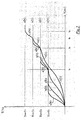
- the nozzle 41 since the nozzle 41 has a thermal inertia I 4 lower than that of the other structural units, it will be the first to reach temperature T h1 (curve a in figure 2 ), followed in the order by the gear pump assembly 31 (which has a thermal inertia I 3 immediately higher than that of the nozzle 41 - curve b), the extrusion screw 21 (which has a thermal inertia I 2 immediately higher than that of the pump assembly 31 - curve c), and the housing 11 (which has a thermal inertia I 1 immediately higher than that of the extrusion screw 21 - curve d).
- control units 110, 130 and 140 are automatically set to a second temperature value T h2 equal or close to that of the second lower working temperature in the set of temperatures Ti described above, substantially corresponding to the working temperature T 2 of the housing 11 (for example, about 80°C).
- control units 130 and 140 are automatically set to a third temperature value T h3 equal or close to that of the third lower working temperature in the set of temperatures Ti described above, substantially corresponding to the working temperature T 3 of the gear pump assembly 31 (for example, about 100°C).
- control unit 140 is automatically set to a fourth temperature value T h4 substantially equal or close to the working temperature T 4 of nozzle 41 (for example about 110°C).
- the feeding of the elastomeric material into the hopper 12 of the extrusion device 1 can take place so as to obtain the semi-finished product 100 made of elastomeric material.
- Such semi-finished product 100 is in turn suitable for being used, in the preferred embodiments of the present invention, for building a component made of elastomeric material of a tyre for vehicle wheels by deposition on the outer surface 50a of said forming support 50.
- Control units 110, 120, 130 and 140 are suitable for resuming the heating of one or more structural units whose working temperature has already been reached, if one of the working temperatures already reached would drop below a predetermined threshold value before the last working temperature is reached by the corresponding structural unit.
- the heating temperatures T h1 -T h4 are indicated as equal to the working temperatures T 1 -T 4 for simplicity of description only, said temperatures may anyway actually be not exactly matching.
- the above method may be carried out on extrusion devices consisting of just two structural units too, or on extrusion devices consisting of more than four structural units.
- the setting and heating operations described above are iteratively repeated multiple times and each time only for the structural units having working temperature Ti higher than the heating temperature T hi set lastly, until all the structural units of the extrusion device have reached the respective working temperature.
Description
- The present invention relates to a method for controlling the heating of an extrusion device of a semi-finished product made of elastomeric material.
- Preferably, the above-mentioned method is carried out in a process for building a component made of elastomeric material of a tyre for vehicle wheels.
- Throughout the following description and in the subsequent claims, the expression "elastomeric material" is used to indicate a composition comprising at least one elastomeric polymer and at least one reinforcing filler. Preferably, such composition further comprises additives such as, for example, a cross-linking agent and/or a plasticizer. Thanks to the presence of the cross-linking agent, such material may be cross-linked by heating, so as to make the end product.
- The expression "semi-finished product made of elastomeric material", on the other hand, is used to indicate an elongated element made of elastomeric material only and having a flat shape.
- The expression "component made of elastomeric material" is used to indicate any component of the tyre, or a part thereof, obtained from said semi-finished product and thus comprising elastomeric material only.
- Throughout the present description and in the subsequent claims, "thermal inertia" of a structural unit of an extrusion device indicates the tendency of a structural unit to withstand changes in temperature; it is higher when the mass of material constituting such structural unit is greater.
- On the other hand, "working temperature" of a structural unit of the extrusion device indicates the temperature at which such structural unit is maintained during the extrusion process. This implies that at temperatures lower than the operating one, the extrusion process does not take place.
- As known, a tyre for vehicle wheels generally comprises a carcass structure comprising at least one carcass ply formed of reinforcing cords incorporated in an elastomeric matrix. The carcass ply has end edges respectively engaged with annular anchoring structures. The latter are arranged in the areas of the tyre usually identified by the name "beads" and they are normally formed each by a substantially circumferential annular insert on which at least one filling insert is applied, in a radially outer position thereof. Such annular inserts are commonly identified as "bead cores" and have the task of keeping the tyre firmly fixed to the anchoring seat specifically provided in the rim of the wheel, thus preventing, in operation, the radially inner end edge of the tyre coming out from such a seat.
- At the beads specific reinforcement structures may be provided having the function of improving the torque transmission to the tyre.
- In tyres devoid of inner tube, called "tubeless", an airtight coating layer made of elastomeric material, typically called liner, is typically provided in a radially inner position with respect to the carcass ply/plies.
- In a radially outer position with respect to the carcass structure, on the other hand, a belt structure is associated.
- The belt structure comprises one or more belt layers arranged radially one on top on the other and having textile or metallic reinforcement cords arranged preferably according to an inclined orientation with respect to the circumferential direction of the tyre and normally crossed with respect to the cords of the possible adjacent belt layer.
- The belt structure can further comprise at least one reinforcing structure defined by at least one continuous reinforcing elongated element including at least one textile or metallic reinforcement cord incorporated in a matrix of elastomeric material and extending parallel to the longitudinal direction of the elongated element itself.
- Between the carcass structure and the belt structure a layer of elastomeric material, called "under-belt", can be provided, said layer having the function of making the radially outer surface of the carcass structure as uniform as possible for the subsequent application of the belt structure.
- In a radially outer position with respect to the belt structure a tread band is applied, also made of elastomeric material, as well as other structural elements making up the tyre.
- Respective sidewalls of elastomeric material are also applied on the side surfaces of the carcass structure, each extending from one of the side edges of the tread band up to the respective annular anchoring structure to the beads.
- From the above description it is clear that a tyre for vehicle wheels typically comprises a plurality of components made of elastomeric material only, according to the definition given above. Among them the following components can be identified, as non-limiting examples: tread band, sidewalls, the so-called under-belt and/or under-layer layers, filling inserts of the annular anchoring structures, liner, sub-liner, sidewall inserts, reinforcing inserts, etc.
- The above-mentioned components may be made starting from semi-finished products made of elastomeric material only, obtained by an extrusion process. The extruded semi-finished product is then laid on a forming support which can rotate about a rotation axis, so as to obtain a deposition preferably according to adjacent and/or at least partly superimposed coils, depending on the component to be made.
- Typically, the extrusion process is carried out in a device consisting of a plurality of structural units having different mass, thermal inertia and working temperature, where at least some structural units having low mass and thermal inertia have a high working temperature and vice versa.
- Prior to feeding the elastomeric material into the extrusion device, all of the above structural units are brought to the respective working temperature.
-
US 2003/047828A1 describes that heat-up characteristic are obtained individually for a plurality of heat zones of an injection molding machine. A heat-up time is obtained from the heat-up characteristic of each heat zone and the difference between a preset temperature and an actual temperature. A heat-zone that requires the logest heat-up time is specified. Heat-up of each heat zone is controlled in accordance with the longest heat-up time. -
JP 1 267022A -
JP 2002-361705A -
JP 2 309408A -
WO 2006/037369 , in the name of the Applicant, recites that in a process for manufacturing an elastomeric tyre component, the elastomeric component is fed to an extruding device comprising a plurality of units each having a respective working temperature. Said units are heated to reach the respective working temperature, starting from the unit having the lowest working temperature up to the unit having the highest working temperature. - The Applicant has considered that, in order to ensure that during the extrusion process the elastomeric material fed into the extrusion device has sufficient fluidity at the required operating flow rates and pressures, all of the above units must be heated to reaching the respective working temperature prior to the feeding of the elastomeric material into the extrusion device.
- The Applicant has further considered that in order to minimise the process times, said heating should occur as a whole in the shortest possible time.
- On the other hand, the Applicant has considered that whenever the extrusion process is ended or interrupted, it is advantageous to leave some elastomeric material into the extrusion device to prevent the formation of air bubbles, which would cause troubles upon restart.
- The Applicant has then observed that irrespective of the fact that the extruder is emptied or not, it is not possible to quickly empty the end portion of the machine when it comprises a gear pump and a nozzle (such units normally being those with higher working temperature and smaller mass). In fact, emptying in this case is only possible upon mechanical disassembly, which requires some time.
- Due to the presence of such elastomeric material, it is necessary preventing that reaching the respective working temperature by one of said units causes an excessive and/or prolonged heating of another unit having lower mass and thermal inertia and higher working temperature. In this case there would be an undesired vulcanization of the elastomeric material at the last mentioned unit, with consequent need of disassembling the extrusion device for eliminating any traces of vulcanized material prior to the next use thereof. This is quite burdensome in terms of time and practicality.
- The Applicant has noted that the process described in said
WO 2006/037369 actually allows meeting the at least partly opposed requirements discussed above. - However, the Applicant has observed that in order to allow said process to actually give the desired advantageous effects in the practical embodiment thereof, it is necessary to know the actual mass and thermal inertia of each of the units of the specific extrusion device used. This allows the actual heating profile of each unit to be known so as to determine the exact moment to activate the heating of each unit. In the practice, it would therefore be necessary to run experimental tests on the single units of the specific extrusion device used. According to the Applicant, such procedure is quite burdensome in terms of process times and costs.
- The Applicant has noted that a method suitable for allowing the respective working temperature to be reached by all the units making up the extrusion device as quickly as possible, without risking a vulcanization of the elastomeric material at any one of the above units and without the need of running experimental tests beforehand on the single units of the specific extrusion device used would meet even better the opposed process requirements.
- The Applicant has observed that through a particular heating procedure of said units that may be automatically implemented on any extrusion device, irrespective of the size and/or type thereof, the above results would be achieved without the need of running experimental tests on the single units of the specific extrusion device used.
- Firstly, the Applicant has understood that in order to limit the heating process cycle time as much as possible it is suitable to implement an automatic procedure that initially provides for the simultaneous heating of all the units, thus carrying out a method totally different from that described in
WO 2006/037369 , which instead provides for a predetermined sequence of activation of the heating starting from the unit having the lowest working temperature up to that having the highest working temperature. - The Applicant has further understood that in order to prevent the risk of having a vulcanization of the elastomeric material into the extrusion device, it is advisable that the above heating procedure be such as to allow the units having a low thermal inertia and a high working temperature to be the last ones reaching the respective working temperatures, that is, once the units having higher thermal mass and lower working temperature have reached their working temperatures.
- The Applicant has perceived that such result may be effectively obtained by implementing a heating procedure that at first provides for a simultaneous heating of all the units up to a predetermined temperature value and when a predetermined unit is close to or has reached such temperature, a further simultaneous heating of the other units up to a new temperature value properly predetermined. Such further simultaneous heating is repeated several times and each time only for the units that have not yet reached the respective working temperature, such repetition continuing until all the units of the extrusion device have reached the respective working temperature.
- In particular, the Applicant has found that by carrying out a heating procedure that provides for:
- an initial simultaneous heating of all the units until the unit having the lowest working temperature has reached the working temperature,
- when said unit is close to or has reached said working temperature, a subsequent simultaneous heating of the other units until the working temperature of the unit of said other units whose working temperature is closest to the heating temperature previously set has been reached,
- a repetition of such subsequent heating each time with reference to only the units having working temperature higher than the last set heating temperature and until all the units of the extrusion device have reached the respective working temperature;
- In a first aspect thereof, the present invention therefore relates to a method for controlling the heating of an extrusion device of a semi-finished product made from elastomeric material, the extrusion device comprising a plurality of structural units, each structural unit having a working temperature different to the working temperature of at least one other structural unit and a thermal inertia different to the thermal inertia of at least one other structural unit, the method comprising:
- a) setting, for each structural unit, a heating temperature to a value equal or close to that of the working temperature of the structural unit which has the lowest working temperature;
- b) simultaneously heating all the structural units of said extrusion device;
- c) when the structural unit having the lowest working temperature is approaching or has reached said heating temperature, setting, for the other structural units, a subsequent heating temperature to a value equal or close to that of the working temperature of the structural unit of said other structural units whose working temperature is closest to the heating temperature previously set;
- d) iteratively repeating the operations recited in b) and c), for only those structural units having a working temperature greater than the heating temperature lastly set, until all of the structural units of the extrusion device have reached the respective working temperature.
- The Applicant believes that with the method of the present invention, when a structural unit reaches its working temperature, also the other structural units that have a lower working temperature have substantially already reached such temperature. Advantageously, this reduces the time interval required for each structural unit to reach the respective working temperature, with an advantageous reduction of the overall implementation time of the extrusion process. Moreover, the risk of having a vulcanization of the elastomeric material at a structural unit having low thermal inertia and high working temperature is prevented. In fact, such working temperature is reached lastly and although the heating of said structural unit is relatively fast due to the low thermal inertia, the residence time at the high working temperature before starting the feeding of the elastomeric material is reduced to the minimum.
- The method of the present invention can advantageously be implemented on any extrusion device, preferably those with a gear pump, where mixture is always present at the end portion of the machine which may be removed only by disassembling parts of the machinery (the extruders with opening head and without gear pump usually allow the machine to be fully emptied, thus the cross-linking problem does not occur), irrespective of the number and type of structural units that make up such extrusion device and irrespective of the difference of mass and/or thermal inertia of said structural units. In fact, in order to implement said method it is sufficient to know only the working temperature of each structural unit making up the extrusion device.
- The present invention may have at least one of the following preferred features, taken individually or in combination with the others.
- Preferably, said iterative repetition comprises at least: e) simultaneously heating said other structural units of said extrusion device.
- More preferably, said iterative repetition also comprises at least:
- f) when the structural unit of said other structural units which has the lowest working temperature is approaching or has reached said subsequent heating temperature, setting, for the remaining structural units, a further heating temperature to a value equal or close to that of the working temperature of the structural unit of said remaining structural units whose working temperature is closest to the heating temperature lastly set.
- Even more preferably, said iterative repetition also comprises at least:
- g) iteratively repeating the operations recited in e) and f), for only those structural units having a working temperature greater than the heating temperature lastly set, until all of the structural units of the extrusion device have reached the respective working temperature.
- The above method may be implemented without distinction on extrusion devices having a number of structural units higher than or equal to, two. Just in order to illustrate the present invention in a sufficiently clear and understandable manner, in the previous paragraphs and throughout the following description (as well as in the subsequent claims), reference has been and shall be made to an extrusion device having three or more structural units.
- In the preferred embodiments of the present invention, each structural unit has a working temperature different to the working temperature of all the other structural units.
- Preferably, each structural unit has a thermal inertia different to the thermal inertia of all the other structural units.
- In preferred embodiments of the present invention, said plurality of structural units comprises at least one housing, at least one member for moving the elastomeric material inside said at least one housing and at least one drawing member of the elastomeric material.
- Preferably, said at least one member for moving the elastomeric material comprises an extrusion screw. Such particular moving member has a relatively low working temperature and a predetermined thermal inertia.
- Preferably, said at least one housing has a working temperature higher than that of the member for moving the elastomeric material.
- Preferably, said at least one housing has a thermal inertia higher than that of the member for moving the elastomeric material.
- In the preferred embodiments of the present invention, said at least one drawing member comprises at least one nozzle. Such particular drawing member is characterised in that it has a particularly low thermal inertia and a particularly high working temperature. Therefore, it is a highly critical element as regards the risk of vulcanization discussed above. In this case, the method of the present invention is particularly advantageous since it provides that reaching the working temperature of the nozzle occurs once all the other structural units of the extrusion device have reached their working temperature, thus reducing to the minimum the residence time of the nozzle at such high working temperature before the extrusion process for manufacturing the semi-finished product made of elastomeric material takes place.
- In alternative embodiments, said at least one drawing member comprises at least one pair of calender rollers.
- In the preferred embodiments of the present invention, said plurality of structural units further comprises at least one gear pump assembly arranged between said at least one member for moving the elastomeric material and said at least one drawing member of the elastomeric material. Such pump assembly preferably has a thermal inertia lower than that of the member for moving the elastomeric material and higher than that of the drawing member of the elastomeric material, especially when a nozzle is used as drawing member.
- Preferably, said at least one housing has a working temperature not lower than about 50°C, more preferably not lower than about 60°C.
- Preferably, said at least one housing has a working temperature not higher than about 120°C, more preferably not lower than about 90°C.
- In particularly preferred embodiments of the present invention, said at least one housing has a working temperature comprised between about 50°C and about 120°C, more preferably between about 50°C and about 90°C, even more preferably between about 60°C and 90°C, even more preferably equal to about 80°C.
- Preferably, said at least one member for moving the elastomeric material has a working temperature not lower than about 40°C, more preferably not lower than about 50°C.
- Preferably, said at least one member for moving the elastomeric material has a working temperature not higher than about 120°C, more preferably not higher than about 90°C.
- In particularly preferred embodiments of the present invention, said at least one member for moving the elastomeric material has a working temperature comprised between about 40°C and about 120°C, more preferably between about 50°C and about 90°C, even more preferably equal to about 80°C.
- Preferably, said at least one drawing member has a working temperature not lower than about 70°C, more preferably not lower than about 90°C.
- Preferably, said at least one drawing member has a working temperature not higher than about 130°C, more preferably not higher than about 125°C.
- In particularly preferred embodiments of the present invention, said at least one drawing member has a working temperature comprised between about 70°C and about 130°C, more preferably between about 90°C and about 125°C, even more preferably equal to about 110°C.
- Preferably, said at least one gear pump assembly has a working temperature not lower than about 70°C, more preferably not lower than about 80°C.
- Preferably, said at least one gear pump assembly has a working temperature not higher than about 120°C, more preferably not higher than about 110°C.
- In particularly preferred embodiments of the present invention, said at least one pump assembly has a working temperature comprised between about 70°C and about 120°C, more preferably between about 80°C and about 110°C, even more preferably equal to about 110°C.
- In preferred embodiments of the present invention, the working temperatures of said structural units are such as to define a set of increasing temperatures in the following order: member for moving the elastomeric material, housing, drawing member of the elastomeric material.
- Preferably, the working temperatures of said structural units are such as to define a set of increasing temperatures in the following order: member for moving the elastomeric material, housing, gear pump assembly and drawing member of the elastomeric material.
- In preferred embodiments of the present invention, the thermal inertias of said structural units are such as to define a set of decreasing thermal inertias in the following order: housing, member for moving the elastomeric material, drawing member of the elastomeric material.
- Preferably, the thermal inertias of said structural units are such as to define a set of decreasing thermal inertias in the following order: housing, member for moving the elastomeric material, gear pump assembly and drawing member of the elastomeric material.
- In preferred embodiments of the present invention, said semi-finished product made of elastomeric material has, in the output section of said drawing member, a thickness not smaller than about 0.5 mm, preferably not smaller than about 0.6 mm.
- In preferred embodiments of the present invention, said semi-finished product made of elastomeric material has, in the output section of said drawing member, a thickness not greater than about 4 mm, preferably not greater than about 2 mm.
- In particularly preferred embodiments of the present invention, said semi-finished product made of elastomeric material has, in the output section of said drawing member, a thickness comprised between about 0.5 mm and about 4 mm, more preferably between about 0.6 mm and about 2 mm.
- In a preferred embodiment of the present invention, said semi-finished product made of elastomeric material has, in the output section of said drawing member, a width comprised between about 5 mm and about 25 mm.
- In preferred embodiments of the present invention, the elastomeric material is fed into the extrusion device with a flow rate comprised between about 2 cm3/s and about 50 cm3/s. Advantageously, such flow rate values allow limiting the overall cycle time.
- All the value ranges recited in the present description and in the subsequent claims should be understood as specifically including also any sub-range between any minimum and maximum value belonging to the respective range, even if the minimum and maximum values of such sub-ranges are not explicitly recited in this description.
- Preferably, the heating of the extrusion device is automatically controlled through a remote control unit that also manages the subsequent extrusion of the elastomeric material (when all the structural units of the extrusion device have reached the respective working temperature) for manufacturing the semi-finished product made of elastomeric material.
- Further features and advantages of the present invention will appear more clearly from the following detailed description of some embodiments thereof, made with reference to the attached drawings. In such drawings:
-
figure 1 is a schematic view of an extrusion device that may be used in the method of the present invention; -
figure 2 shows a diagram that illustrates a heating method of the extrusion device offigure 1 according to the present invention. - The present invention has a preferred embodiment thereof in a process for building a component made of elastomeric material of a tyre for vehicle wheels.
- The above-mentioned process is preferably carried out by providing the movement of a first forming support along a first building line for building a carcass structure comprising at least one carcass ply and a pair of annular anchoring structures, and the movement of a second forming support along a second building line for building a crown structure comprising at least one belt structure and a tread band. The carcass structure and the crown structure thus built are transferred, with a synchronised movement in production-frequency and by respective robot arms, to a workstation for assembling and shaping the tyre being processed, where the carcass structure and the crown structure are reciprocally associated so as to obtain a green tyre. Such green tyre is then transferred on a moulding and curing line for obtaining the finished product.
- As an alternative, the process for building a component made from elastomeric material of a tyre for vehicle wheels, wherein the present invention is embodied, may be carried out in a process for building a tyre wherein the single tyre components are directly built, according to a predetermined frequency, on a single forming support, generally toroidal.
- In the above-described processes, the components made of elastomeric material only (such as for example tread band, sidewalls, the so-called under-belt and/or under-layer layers, filling inserts of the annular anchoring structures, liner, sub-liner, sidewall inserts, reinforcing inserts, etc) are obtained starting from a semi-finished product made of elastomeric material only. Such semi-finished product is obtained by extrusion and is laid on a forming support while the latter is moved around a rotation axis thereof, so as to obtain a deposition preferably according to adjacent and/or at least partly superimposed coils, according to the component to be made.
- The extrusion of the semi-finished product takes place at an
extrusion device 1 of the type illustrated infigure 1 . The semi-finished product obtained through such extrusion device is indicated with 100, whereas the forming support whereon suchsemi-finished product 100 is laid is indicated with 50. - The
extrusion device 1 preferably comprises four different structural units, each preferably having mass, thermal inertia (Ii) and working temperature (Ti) different from those of the other structural units. - A first
structural unit 10 of theextrusion device 10 is defined by ahousing 11 in turn defined by a hollow body having a longitudinal axis X-X. Thehousing 11 comprises, at anupstream end portion 11a thereof, ahopper 12 for loading the elastomeric material to be extruded. - A second
structural unit 20 of theextrusion device 10 is defined by anextrusion screw 21 rotatably mounted within thehousing 11. Theextrusion screw 21 acts as a member for moving the elastomeric material within thehousing 11. In particular, theextrusion screw 21 moves the elastomeric material from theupstream end portion 11a ofhousing 11 to adownstream end portion 11b ofhousing 11, along a movement direction generally indicated with A. - A third
structural unit 30 of theextrusion device 10 is preferably defined by agear pump assembly 31 operatively associated with thehousing 11 at thedownstream end portion 11b thereof. Suchgear pump assembly 31 receives the elastomeric material carried by theextrusion screw 21 and pushes it by pressure downstream, with reference to the moving direction A of the elastomeric material. - A fourth
structural unit 40 of theextrusion device 10 is preferably defined by anozzle 41 associated with thegear pump assembly 31 downstream thereof, always with reference to the moving direction A of the elastomeric material. Throughsuch nozzle 41, the elastomeric material pushed by thegear pump assembly 31 is drawn as asemi-finished product 100, to be then laid on theouter surface 50a of the formingsupport 50. - Preferably, the
gear pump assembly 31 pushes the elastomeric material into thenozzle 41 with a pressure not lower than about 30 bar, preferably comprised between about 40 bar and about 600 bar. - The elastomeric material is fed towards the forming
support 50 with a flow rate preferably not lower than about 2 cm3/s, more preferably comprised between about 3 cm3/s and about 50 cm3/s. - In an alternative embodiment (not shown) of the
extrusion device 1 of the present invention, instead of thenozzle 41 it is possible to use a pair of calender rollers as a member for drawing the elastomeric material. -
Nozzle 41 has an output opening for the elastomeric material shaped so as to define asemi-finished product 100 made of elastomeric material having desired shape and dimensions. - In preferred embodiments of the present invention, the
semi-finished product 100 made of elastomeric material is defined by a flat element having, in the output section of said drawing member, a thickness not smaller than about 0.5 mm, preferably not smaller than about 0.6 m, more preferably comprised between about 0.5 mm and about 3 mm, even more preferably comprised between about 0.6 mm and about 2 mm. - Said flat element further has, in the output section of said drawing member, a width preferably comprised between about 5 mm and about 25 mm.
- The working temperatures of said
structural units - The thermal inertias of said
structural units - Preferably, the
housing 11 has a working temperature (T2) comprised between about 50°C and about 120°C, more preferably between about 50°C and about 90°C, even more preferably between about 60°C and 90°C, even more preferably equal to about 80°C. - Preferably, the
extrusion screw 21 has a working temperature (T1) comprised between about 40°C and about 120°C, more preferably between about 50°C and about 90°C, even more preferably equal to about 80°C. - Preferably, the
nozzle 41 has a working temperature (T4) comprised between about 70°C and about 130°C, more preferably between about 90°C and about 125°C, even more preferably equal to about 110°C. - Preferably, the
gear pump assembly 31 has a working temperature (T3) comprised between about 70°C and about 120°C, more preferably between about 80°C and about 110°C, even more preferably equal to about 100°C. - Each of said
structural units - In particular, the
housing 11 is operatively associated with afirst control unit 110, theextrusion screw 21 is operatively associated with asecond control unit 120, thegear pump assembly 31 is operatively associated with athird control unit 130 and thenozzle 41 is operatively associated with afourth control unit 140. - Control units 110-140 are all operatively associated with a
remote control unit 60 which, besides automatically controlling the heating of saidstructural units structural units - The control of the heating of the various
structural units extrusion device 1 of thesemi-finished product 100 made of elastomeric material takes place according to the method described below, with reference tofigure 2 . Such figure shows a diagram having time values expressed in minutes on the abscissa and temperature values expressed in degrees Celsius on the ordinate. - At first, all the control units 110-140 are set to a first heating temperature Th1 having a value equal or close to that of the lowest temperature in the set of temperatures Ti described above, substantially corresponding to the working temperature T1 of the extrusion screw 21 (for example, about 60°C).
- Control units 110-140 are then simultaneously switched on in order to heat all the
structural units structural units structural units - In the specific case of the
extrusion device 1 illustrated infigure 1 , since thenozzle 41 has a thermal inertia I4 lower than that of the other structural units, it will be the first to reach temperature Th1 (curve a infigure 2 ), followed in the order by the gear pump assembly 31 (which has a thermal inertia I3 immediately higher than that of the nozzle 41 - curve b), the extrusion screw 21 (which has a thermal inertia I2 immediately higher than that of the pump assembly 31 - curve c), and the housing 11 (which has a thermal inertia I1 immediately higher than that of the extrusion screw 21 - curve d). - Close to or upon reaching temperature Th1 by the extrusion screw 21 (curve c, time tc),
control units - The simultaneous heating of the
gear pump assembly 31 and of the nozzle 41 (which at time tc have already reached the heating temperature Th1) is then resumed up to reaching temperature Th2. Simultaneously with said heating, the heating of the housing 11 (which at time tc has not yet reached the heating temperature Th1) continues up to reaching temperature Th2. - Close to or upon reaching temperature Th2 by the housing 11 (curve d, time td),
control units - The simultaneous heating of the
gear pump assembly 31 and of the nozzle 41 (which at time td have already reached the heating temperature Th2) is then resumed up to reaching temperature Th3. - Close to or upon reaching temperature Th3 by the gear pump assembly (curve b, time tb), the
control unit 140 is automatically set to a fourth temperature value Th4 substantially equal or close to the working temperature T4 of nozzle 41 (for example about 110°C). - The heating of nozzle 41 (which at time tb has already reached the heating temperature Th3) is then resumed up to reaching the working temperature T4 thereof (curve a, time ta).
- At this point, since all the
structural units extrusion device 1 have reached the respective working temperature T1-T4, the feeding of the elastomeric material into thehopper 12 of theextrusion device 1 can take place so as to obtain thesemi-finished product 100 made of elastomeric material. Suchsemi-finished product 100 is in turn suitable for being used, in the preferred embodiments of the present invention, for building a component made of elastomeric material of a tyre for vehicle wheels by deposition on theouter surface 50a of said formingsupport 50. -
Control units - In the diagram of
figure 2 , the heating temperatures Th1-Th4 are indicated as equal to the working temperatures T1-T4 for simplicity of description only, said temperatures may anyway actually be not exactly matching. - From the above description it is clear that the risk of having a vulcanization of the elastomeric material inside the nozzle 41 (which is the structural unit having the lowest thermal inertia and the highest working temperature) is substantially eliminated due to the fact that
such nozzle 41 reaches the working temperature T4 lastly, that is, after the otherstructural units nozzle 41 is relatively quick due to the low thermal inertia thereof, the residence time ofnozzle 41 at the respective high working temperature T4 before starting the extrusion process is minimised in this way. - It is also clear that the time required for bringing all the
structural units structural units - The above method may be carried out on extrusion devices consisting of just two structural units too, or on extrusion devices consisting of more than four structural units. In this last-mentioned case, the setting and heating operations described above are iteratively repeated multiple times and each time only for the structural units having working temperature Ti higher than the heating temperature Thi set lastly, until all the structural units of the extrusion device have reached the respective working temperature.
Claims (20)
- Method for controlling the heating of an extrusion device (1) of a semi-finished product made of elastomeric material (100), the extrusion device (1) comprising a plurality of structural units (10,11; 20,21; 30,31; 40,41), each structural unit (10,11; 20,21; 30,31; 40,41) having a working temperature (T1, T2, T3, T4) different to the working temperature of at least one other structural unit and a thermal inertia (I1, I2, I3, I4) different to the thermal inertia of at least one other structural unit, the method comprising:a) setting, for each structural unit (10,11; 20,21; 30,31; 40,41), a heating temperature (Th1) to a value equal or close to that of the working temperature (T1) of the structural unit (20,21) which has the lowest working temperature;b) simultaneously heating all the structural units (10,11; 20,21; 30,31; 40,41) of said extrusion device (1);c) when the structural unit (20,21) having the lowest working temperature is approaching or has reached said heating temperature (Th1), setting, for the other structural units (10,11; 30,31; 40,41), a subsequent heating temperature (Th2) to a value equal or close to that of the working temperature (T2) of the structural unit (10,11) of said other structural units (10,11; 30,31; 40,41) whose working temperature is closest to the heating temperature (Th1) previously set;d) iteratively repeating the operations recited in b) and c), for only the structural units (30,31; 40,41) having a working temperature (T3, T4) greater than the heating temperature (Th2) lastly set, until all of the structural units (10,11; 20,21; 30,31; 40,41) of the extrusion device (1) have reached the respective working temperature (T1, T2, T3, T4).
- Method according to claim 1, wherein said iterative repetition comprises at least:e) simultaneously heating said other structural units (10,11; 30,31; 40,41) of said extrusion device (1).
- Method according to claim 1 or 2, wherein said iterative repetition comprises at least:f) when the structural unit (10,11) of said other structural units (10,11; 30,31; 40,41) which has the lowest working temperature is approaching or has reached said subsequent heating temperature (Th2), setting, for the remaining structural units (30,31; 40,41), a further heating temperature (Th3) to a value equal or close to that of the working temperature (T3) of the structural unit (30,31) of said remaining structural units (30,31; 40,41) whose working temperature is closest to the heating temperature (Th2) lastly set.
- Method according to claim 3 when depending on claim 2, wherein said iterative repetition comprises at least:g) iteratively repeating the operations recited in e) and f), for only the structural units (40,41) having a working temperature (T4) greater than the heating temperature (Th3) lastly set, until all of the structural units (10,11; 20,21; 30,31; 40,41) of the extrusion device (1) have reached the respective working temperature (T1, T2, T3, T4).
- Method according to claim 1, wherein each structural unit (10,11; 20,21; 30,31; 40,41) has a working temperature (T1, T2, T3, T4) different to the working temperature of all the other structural units.
- Method according to any one of the previous claims, wherein each structural unit (10,11; 20,21; 30,31; 40,41) has a thermal inertia (I1, I2, I3, I4) different to the thermal inertia of all the other structural units.
- Method according to any one of the previous claims, wherein said plurality of structural units (10,11; 20,21; 30,31; 40,41) comprises at least one housing (11), at least one member (21) for moving the elastomeric material inside said at least one housing (11) and at least one drawing member (41) of the elastomeric material.
- Method according to claim 7, wherein said at least one drawing member comprises at least one nozzle (41).
- Method according to claim 7 or 8, wherein said plurality of structural units (10,11; 20,21; 30,31; 40,41) further comprises at least one gear pump assembly (31) arranged between said at least one member (21) for moving the elastomeric material and said at least one drawing member (41) of the elastomeric material.
- Method according to any one of claims 7 to 9, wherein said at least one housing (11) has a working temperature (T2) of between about 50°C and about 120°C.
- Method according to any one of claims 7 to 10, wherein said at least one member (21) for moving the elastomeric material has a working temperature (T1) of between about 40°C and about 120°C.
- Method according to any one of claims 7 to 11, wherein said at least one drawing member (41) has a working temperature (T4) of between about 70°C and about 130°C.
- Method according to any one of claims 9 to 12, wherein said at least one gear pump assembly (31) has a working temperature (T3) of between about 70°C and about 120°C.
- Method according to any one of claims 7 to 13, wherein the working temperatures (T1, T2, T3, T4) of said structural units (10,11; 20,21; 30,31; 40,41) are such as to define a set of temperatures (Ti) increasing in the following order: member (21) for moving the elastomeric material, housing (11), drawing member (41) of the elastomeric material.
- Method according to any one of claims 9 to 14, wherein the working temperatures (T1, T2, T3, T4) of said structural units (10,11; 20,21; 30,31; 40,41) are such as to define a set of temperatures (Ti) increasing in the following order: member (21) for moving the elastomeric material, housing (11), gear pump assembly (31) and drawing member (41) of the elastomeric material.
- Method according to any one of claims 7 to 15, wherein the thermal inertias (I1, I2, I3, I4) of said structural units (10,11; 20,21; 30,31; 40,41) are such as to define a set of thermal inertias (Ii) decreasing in the following order: housing (11), member (21) for moving the elastomeric material, drawing member (41) of the elastomeric material.
- Method according to any one of claims 9 to 16, wherein the thermal inertias (I1, I2, I3, I4) of said structural units (10,11; 20,21; 30,31; 40,41) are such as to define a set of thermal inertias (Ii) decreasing in the following order: housing (11), member (21) for moving the elastomeric material, gear pump assembly (31) and drawing member (41) of the elastomeric material.
- Method according to any one of claims 7 to 17, wherein said semi-finished product made of elastomeric material (100) has, in an output section of said drawing member (41), a thickness of between about 0.5 mm and about 4 mm.
- Method according to any one of claims 7 to 18, wherein said semi-finished product made of elastomeric material (100) has, in an output section of said drawing member (41), a width of between about 5 mm and about 25 mm.
- Method according to any one of the previous claims, wherein the elastomeric material is fed into the extrusion device (1) with a flow rate of between about 2 cm3/s and about 50 cm3/s.
Applications Claiming Priority (3)
| Application Number | Priority Date | Filing Date | Title |
|---|---|---|---|
| ITMI20101171 | 2010-06-28 | ||
| US36288910P | 2010-07-09 | 2010-07-09 | |
| PCT/IB2011/001515 WO2012001492A1 (en) | 2010-06-28 | 2011-06-27 | Method for controlling the heating - up of an extrusion device for producing elastomeric semi - finished product |
Publications (2)
| Publication Number | Publication Date |
|---|---|
| EP2585272A1 EP2585272A1 (en) | 2013-05-01 |
| EP2585272B1 true EP2585272B1 (en) | 2017-08-23 |
Family
ID=43558468
Family Applications (1)
| Application Number | Title | Priority Date | Filing Date |
|---|---|---|---|
| EP11743336.7A Active EP2585272B1 (en) | 2010-06-28 | 2011-06-27 | Method for controlling the heating-up of an extrusion device for producing an elastomeric semi-finished product |
Country Status (7)
| Country | Link |
|---|---|
| US (1) | US9403309B2 (en) |
| EP (1) | EP2585272B1 (en) |
| JP (1) | JP5802271B2 (en) |
| KR (1) | KR101860449B1 (en) |
| CN (1) | CN102958671B (en) |
| BR (1) | BR112012031733B1 (en) |
| WO (1) | WO2012001492A1 (en) |
Families Citing this family (8)
| Publication number | Priority date | Publication date | Assignee | Title |
|---|---|---|---|---|
| JP5984755B2 (en) * | 2013-07-23 | 2016-09-06 | 株式会社神戸製鋼所 | Resin discharge mechanism |
| KR102295482B1 (en) * | 2014-02-25 | 2021-08-27 | 세이이치 유야마 | 3d printer |
| WO2017109744A1 (en) | 2015-12-24 | 2017-06-29 | Pirelli Tyre S.P.A. | Extrusion device and process for extruding a semi-finished product made of elastomeric material |
| US10532512B2 (en) * | 2018-06-07 | 2020-01-14 | Thermwood Corporation | Additive manufacturing apparatus |
| CN111791449A (en) * | 2020-07-29 | 2020-10-20 | 泰州市光明电子材料有限公司 | Polytetrafluoroethylene extrusion pipe forming equipment |
| WO2022076688A1 (en) * | 2020-10-09 | 2022-04-14 | Mackay Michael E | Positive displacement pump material delivery system for additive manufacture |
| AU2021266284B2 (en) | 2020-11-16 | 2023-03-16 | Commonwealth Scientific And Industrial Research Organisation | Material extruder |
| IT202000029222A1 (en) | 2020-12-01 | 2022-06-01 | Pirelli | Extrusion method of a semi-finished product in elastomeric material |
Family Cites Families (19)
| Publication number | Priority date | Publication date | Assignee | Title |
|---|---|---|---|---|
| US4843576A (en) * | 1987-04-15 | 1989-06-27 | Westinghouse Electric Corp. | Temperature control arrangement for an extruding process |
| JP2530685B2 (en) | 1988-04-19 | 1996-09-04 | 東芝機械株式会社 | Automatic temperature raising method for multi-zone temperature control system such as extruder |
| JPH02111515U (en) * | 1989-02-20 | 1990-09-06 | ||
| JPH02309408A (en) | 1989-05-24 | 1990-12-25 | Sekisui Chem Co Ltd | System and method for automatic temperature rise control |
| JPH08281754A (en) * | 1995-04-07 | 1996-10-29 | Japan Steel Works Ltd:The | Heating method of cylinder heater for injection molding machine |
| JPH0976321A (en) | 1995-09-08 | 1997-03-25 | Japan Steel Works Ltd:The | Starter for injection molding machine |
| JPH09237337A (en) | 1996-03-01 | 1997-09-09 | Ricoh Co Ltd | Image display device |
| JP3611667B2 (en) * | 1996-04-19 | 2005-01-19 | ファナック株式会社 | Temperature control method for injection molding machine |
| JP2835033B2 (en) * | 1996-07-17 | 1998-12-14 | 株式会社名機製作所 | Method and apparatus for controlling temperature of heating cylinder of injection molding machine |
| US6313212B1 (en) | 1997-09-25 | 2001-11-06 | Pirelli Coordinamento Pneumatici S.P.A. | Continuous process for producing semi-finished rubber products with a silica reinforcing filler, for tyres, and tyres thus produced |
| EP0928680B1 (en) | 1997-12-30 | 2003-03-12 | Pirelli Pneumatici Societa' Per Azioni | A method for making tyres for vehicle wheels |
| JP3824502B2 (en) * | 2001-06-11 | 2006-09-20 | 日精樹脂工業株式会社 | Temperature control method and apparatus for injection molding machine |
| JP2003080576A (en) | 2001-09-10 | 2003-03-19 | Fanuc Ltd | Method and apparatus for controlling temperature of injection molding machine |
| JP2004199526A (en) * | 2002-12-19 | 2004-07-15 | Toshiba Mach Co Ltd | Heating control method, heating control program and heating control device |
| US7341640B2 (en) | 2004-02-27 | 2008-03-11 | Toyo Tire & Rubber Co., Ltd. | Method of and apparatus for forming rubber strip materials for building tires and method of building tires |
| BRPI0419096B1 (en) | 2004-10-08 | 2014-10-29 | Pirelli | "PROCESS FOR MANUFACTURING AN ELASTOMIC TIRE COMPONENT". |
| CN200945701Y (en) * | 2006-07-21 | 2007-09-12 | 张守志 | Cooling device of tyre adhesive tape extrusion machine |
| CN201012535Y (en) * | 2007-01-31 | 2008-01-30 | 中国化学工业桂林工程公司 | Hydraulic pressure composite head of the composite multiple rubber material extruding machine |
| PL2258541T3 (en) | 2007-09-27 | 2017-04-28 | Pirelli Tyre S.P.A. | Process and plant for producing tyres for vehicle wheels |
-
2011
- 2011-06-27 CN CN201180030362.XA patent/CN102958671B/en active Active
- 2011-06-27 JP JP2013517568A patent/JP5802271B2/en active Active
- 2011-06-27 KR KR1020127033188A patent/KR101860449B1/en active IP Right Grant
- 2011-06-27 US US13/807,177 patent/US9403309B2/en active Active
- 2011-06-27 WO PCT/IB2011/001515 patent/WO2012001492A1/en active Application Filing
- 2011-06-27 BR BR112012031733-4A patent/BR112012031733B1/en active IP Right Grant
- 2011-06-27 EP EP11743336.7A patent/EP2585272B1/en active Active
Non-Patent Citations (1)
| Title |
|---|
| None * |
Also Published As
| Publication number | Publication date |
|---|---|
| BR112012031733A2 (en) | 2017-05-23 |
| CN102958671A (en) | 2013-03-06 |
| US9403309B2 (en) | 2016-08-02 |
| BR112012031733B1 (en) | 2020-02-11 |
| EP2585272A1 (en) | 2013-05-01 |
| KR101860449B1 (en) | 2018-07-02 |
| KR20130119331A (en) | 2013-10-31 |
| CN102958671B (en) | 2016-01-20 |
| JP2013534481A (en) | 2013-09-05 |
| JP5802271B2 (en) | 2015-10-28 |
| WO2012001492A1 (en) | 2012-01-05 |
| US20130106011A1 (en) | 2013-05-02 |
Similar Documents
| Publication | Publication Date | Title |
|---|---|---|
| EP2585272B1 (en) | Method for controlling the heating-up of an extrusion device for producing an elastomeric semi-finished product | |
| US11623187B2 (en) | Extrusion device and process for extruding a semi-finished product made of elastomeric material | |
| EP1509386B1 (en) | A method and apparatus for manufacturing elastomeric material components of a tyre for vehicle wheels | |
| EP2049324B1 (en) | Process and apparatus for building pneumatic tyres | |
| US7341640B2 (en) | Method of and apparatus for forming rubber strip materials for building tires and method of building tires | |
| EP1817157B1 (en) | Method and apparatus for manufacturing a tyre for vehicle wheels | |
| EP1638756B1 (en) | A process for manufacturing elastomeric components of a tyre for vehicle wheels | |
| EP1799427B1 (en) | Process for manufacturing elastomeric tire components | |
| EP3112141B1 (en) | Apparatus and method for forming an elastomeric strip | |
| US20200070395A1 (en) | Method of forming an elastomeric strip | |
| EP4255713A1 (en) | Method for extruding a semi-finished product made of elastomeric material |
Legal Events
| Date | Code | Title | Description |
|---|---|---|---|
| PUAI | Public reference made under article 153(3) epc to a published international application that has entered the european phase |
Free format text: ORIGINAL CODE: 0009012 |
|
| 17P | Request for examination filed |
Effective date: 20121122 |
|
| AK | Designated contracting states |
Kind code of ref document: A1 Designated state(s): AL AT BE BG CH CY CZ DE DK EE ES FI FR GB GR HR HU IE IS IT LI LT LU LV MC MK MT NL NO PL PT RO RS SE SI SK SM TR |
|
| DAX | Request for extension of the european patent (deleted) | ||
| RAP1 | Party data changed (applicant data changed or rights of an application transferred) |
Owner name: PIRELLI TYRE S.P.A. |
|
| GRAP | Despatch of communication of intention to grant a patent |
Free format text: ORIGINAL CODE: EPIDOSNIGR1 |
|
| INTG | Intention to grant announced |
Effective date: 20170420 |
|
| RIN1 | Information on inventor provided before grant (corrected) |
Inventor name: AMURRI, CESARE, EMANUELE |
|
| GRAS | Grant fee paid |
Free format text: ORIGINAL CODE: EPIDOSNIGR3 |
|
| GRAA | (expected) grant |
Free format text: ORIGINAL CODE: 0009210 |
|
| AK | Designated contracting states |
Kind code of ref document: B1 Designated state(s): AL AT BE BG CH CY CZ DE DK EE ES FI FR GB GR HR HU IE IS IT LI LT LU LV MC MK MT NL NO PL PT RO RS SE SI SK SM TR |
|
| REG | Reference to a national code |
Ref country code: GB Ref legal event code: FG4D |
|
| REG | Reference to a national code |
Ref country code: CH Ref legal event code: EP |
|
| REG | Reference to a national code |
Ref country code: AT Ref legal event code: REF Ref document number: 920856 Country of ref document: AT Kind code of ref document: T Effective date: 20170915 |
|
| REG | Reference to a national code |
Ref country code: IE Ref legal event code: FG4D |
|
| REG | Reference to a national code |
Ref country code: DE Ref legal event code: R096 Ref document number: 602011040872 Country of ref document: DE |
|
| REG | Reference to a national code |
Ref country code: RO Ref legal event code: EPE |
|
| REG | Reference to a national code |
Ref country code: NL Ref legal event code: MP Effective date: 20170823 |
|
| REG | Reference to a national code |
Ref country code: LT Ref legal event code: MG4D |
|
| REG | Reference to a national code |
Ref country code: AT Ref legal event code: MK05 Ref document number: 920856 Country of ref document: AT Kind code of ref document: T Effective date: 20170823 |
|
| PG25 | Lapsed in a contracting state [announced via postgrant information from national office to epo] |
Ref country code: HR Free format text: LAPSE BECAUSE OF FAILURE TO SUBMIT A TRANSLATION OF THE DESCRIPTION OR TO PAY THE FEE WITHIN THE PRESCRIBED TIME-LIMIT Effective date: 20170823 Ref country code: AT Free format text: LAPSE BECAUSE OF FAILURE TO SUBMIT A TRANSLATION OF THE DESCRIPTION OR TO PAY THE FEE WITHIN THE PRESCRIBED TIME-LIMIT Effective date: 20170823 Ref country code: LT Free format text: LAPSE BECAUSE OF FAILURE TO SUBMIT A TRANSLATION OF THE DESCRIPTION OR TO PAY THE FEE WITHIN THE PRESCRIBED TIME-LIMIT Effective date: 20170823 Ref country code: NL Free format text: LAPSE BECAUSE OF FAILURE TO SUBMIT A TRANSLATION OF THE DESCRIPTION OR TO PAY THE FEE WITHIN THE PRESCRIBED TIME-LIMIT Effective date: 20170823 Ref country code: FI Free format text: LAPSE BECAUSE OF FAILURE TO SUBMIT A TRANSLATION OF THE DESCRIPTION OR TO PAY THE FEE WITHIN THE PRESCRIBED TIME-LIMIT Effective date: 20170823 Ref country code: SE Free format text: LAPSE BECAUSE OF FAILURE TO SUBMIT A TRANSLATION OF THE DESCRIPTION OR TO PAY THE FEE WITHIN THE PRESCRIBED TIME-LIMIT Effective date: 20170823 Ref country code: NO Free format text: LAPSE BECAUSE OF FAILURE TO SUBMIT A TRANSLATION OF THE DESCRIPTION OR TO PAY THE FEE WITHIN THE PRESCRIBED TIME-LIMIT Effective date: 20171123 |
|
| PG25 | Lapsed in a contracting state [announced via postgrant information from national office to epo] |
Ref country code: LV Free format text: LAPSE BECAUSE OF FAILURE TO SUBMIT A TRANSLATION OF THE DESCRIPTION OR TO PAY THE FEE WITHIN THE PRESCRIBED TIME-LIMIT Effective date: 20170823 Ref country code: PL Free format text: LAPSE BECAUSE OF FAILURE TO SUBMIT A TRANSLATION OF THE DESCRIPTION OR TO PAY THE FEE WITHIN THE PRESCRIBED TIME-LIMIT Effective date: 20170823 Ref country code: GR Free format text: LAPSE BECAUSE OF FAILURE TO SUBMIT A TRANSLATION OF THE DESCRIPTION OR TO PAY THE FEE WITHIN THE PRESCRIBED TIME-LIMIT Effective date: 20171124 Ref country code: RS Free format text: LAPSE BECAUSE OF FAILURE TO SUBMIT A TRANSLATION OF THE DESCRIPTION OR TO PAY THE FEE WITHIN THE PRESCRIBED TIME-LIMIT Effective date: 20170823 Ref country code: IS Free format text: LAPSE BECAUSE OF FAILURE TO SUBMIT A TRANSLATION OF THE DESCRIPTION OR TO PAY THE FEE WITHIN THE PRESCRIBED TIME-LIMIT Effective date: 20171223 Ref country code: ES Free format text: LAPSE BECAUSE OF FAILURE TO SUBMIT A TRANSLATION OF THE DESCRIPTION OR TO PAY THE FEE WITHIN THE PRESCRIBED TIME-LIMIT Effective date: 20170823 Ref country code: BG Free format text: LAPSE BECAUSE OF FAILURE TO SUBMIT A TRANSLATION OF THE DESCRIPTION OR TO PAY THE FEE WITHIN THE PRESCRIBED TIME-LIMIT Effective date: 20171123 |
|
| PG25 | Lapsed in a contracting state [announced via postgrant information from national office to epo] |
Ref country code: CZ Free format text: LAPSE BECAUSE OF FAILURE TO SUBMIT A TRANSLATION OF THE DESCRIPTION OR TO PAY THE FEE WITHIN THE PRESCRIBED TIME-LIMIT Effective date: 20170823 Ref country code: DK Free format text: LAPSE BECAUSE OF FAILURE TO SUBMIT A TRANSLATION OF THE DESCRIPTION OR TO PAY THE FEE WITHIN THE PRESCRIBED TIME-LIMIT Effective date: 20170823 |
|
| REG | Reference to a national code |
Ref country code: DE Ref legal event code: R097 Ref document number: 602011040872 Country of ref document: DE |
|
| PG25 | Lapsed in a contracting state [announced via postgrant information from national office to epo] |
Ref country code: SM Free format text: LAPSE BECAUSE OF FAILURE TO SUBMIT A TRANSLATION OF THE DESCRIPTION OR TO PAY THE FEE WITHIN THE PRESCRIBED TIME-LIMIT Effective date: 20170823 Ref country code: SK Free format text: LAPSE BECAUSE OF FAILURE TO SUBMIT A TRANSLATION OF THE DESCRIPTION OR TO PAY THE FEE WITHIN THE PRESCRIBED TIME-LIMIT Effective date: 20170823 Ref country code: EE Free format text: LAPSE BECAUSE OF FAILURE TO SUBMIT A TRANSLATION OF THE DESCRIPTION OR TO PAY THE FEE WITHIN THE PRESCRIBED TIME-LIMIT Effective date: 20170823 |
|
| REG | Reference to a national code |
Ref country code: FR Ref legal event code: PLFP Year of fee payment: 8 |
|
| PLBE | No opposition filed within time limit |
Free format text: ORIGINAL CODE: 0009261 |
|
| STAA | Information on the status of an ep patent application or granted ep patent |
Free format text: STATUS: NO OPPOSITION FILED WITHIN TIME LIMIT |
|
| 26N | No opposition filed |
Effective date: 20180524 |
|
| PG25 | Lapsed in a contracting state [announced via postgrant information from national office to epo] |
Ref country code: SI Free format text: LAPSE BECAUSE OF FAILURE TO SUBMIT A TRANSLATION OF THE DESCRIPTION OR TO PAY THE FEE WITHIN THE PRESCRIBED TIME-LIMIT Effective date: 20170823 |
|
| REG | Reference to a national code |
Ref country code: DE Ref legal event code: R079 Ref document number: 602011040872 Country of ref document: DE Free format text: PREVIOUS MAIN CLASS: B29C0047780000 Ipc: B29C0048780000 |
|
| REG | Reference to a national code |
Ref country code: CH Ref legal event code: PL |
|
| REG | Reference to a national code |
Ref country code: BE Ref legal event code: MM Effective date: 20180630 |
|
| PG25 | Lapsed in a contracting state [announced via postgrant information from national office to epo] |
Ref country code: LU Free format text: LAPSE BECAUSE OF NON-PAYMENT OF DUE FEES Effective date: 20180627 Ref country code: MC Free format text: LAPSE BECAUSE OF FAILURE TO SUBMIT A TRANSLATION OF THE DESCRIPTION OR TO PAY THE FEE WITHIN THE PRESCRIBED TIME-LIMIT Effective date: 20170823 |
|
| REG | Reference to a national code |
Ref country code: IE Ref legal event code: MM4A |
|
| PG25 | Lapsed in a contracting state [announced via postgrant information from national office to epo] |
Ref country code: IE Free format text: LAPSE BECAUSE OF NON-PAYMENT OF DUE FEES Effective date: 20180627 Ref country code: CH Free format text: LAPSE BECAUSE OF NON-PAYMENT OF DUE FEES Effective date: 20180630 Ref country code: LI Free format text: LAPSE BECAUSE OF NON-PAYMENT OF DUE FEES Effective date: 20180630 |
|
| PG25 | Lapsed in a contracting state [announced via postgrant information from national office to epo] |
Ref country code: BE Free format text: LAPSE BECAUSE OF NON-PAYMENT OF DUE FEES Effective date: 20180630 |
|
| PG25 | Lapsed in a contracting state [announced via postgrant information from national office to epo] |
Ref country code: MT Free format text: LAPSE BECAUSE OF NON-PAYMENT OF DUE FEES Effective date: 20180627 |
|
| PG25 | Lapsed in a contracting state [announced via postgrant information from national office to epo] |
Ref country code: TR Free format text: LAPSE BECAUSE OF FAILURE TO SUBMIT A TRANSLATION OF THE DESCRIPTION OR TO PAY THE FEE WITHIN THE PRESCRIBED TIME-LIMIT Effective date: 20170823 |
|
| PG25 | Lapsed in a contracting state [announced via postgrant information from national office to epo] |
Ref country code: HU Free format text: LAPSE BECAUSE OF FAILURE TO SUBMIT A TRANSLATION OF THE DESCRIPTION OR TO PAY THE FEE WITHIN THE PRESCRIBED TIME-LIMIT; INVALID AB INITIO Effective date: 20110627 Ref country code: PT Free format text: LAPSE BECAUSE OF FAILURE TO SUBMIT A TRANSLATION OF THE DESCRIPTION OR TO PAY THE FEE WITHIN THE PRESCRIBED TIME-LIMIT Effective date: 20170823 |
|
| PG25 | Lapsed in a contracting state [announced via postgrant information from national office to epo] |
Ref country code: MK Free format text: LAPSE BECAUSE OF NON-PAYMENT OF DUE FEES Effective date: 20170823 Ref country code: CY Free format text: LAPSE BECAUSE OF FAILURE TO SUBMIT A TRANSLATION OF THE DESCRIPTION OR TO PAY THE FEE WITHIN THE PRESCRIBED TIME-LIMIT Effective date: 20170823 |
|
| PG25 | Lapsed in a contracting state [announced via postgrant information from national office to epo] |
Ref country code: AL Free format text: LAPSE BECAUSE OF FAILURE TO SUBMIT A TRANSLATION OF THE DESCRIPTION OR TO PAY THE FEE WITHIN THE PRESCRIBED TIME-LIMIT Effective date: 20170823 |
|
| PGFP | Annual fee paid to national office [announced via postgrant information from national office to epo] |
Ref country code: RO Payment date: 20230606 Year of fee payment: 13 Ref country code: FR Payment date: 20230626 Year of fee payment: 13 Ref country code: DE Payment date: 20230626 Year of fee payment: 13 |
|
| PGFP | Annual fee paid to national office [announced via postgrant information from national office to epo] |
Ref country code: IT Payment date: 20230620 Year of fee payment: 13 Ref country code: GB Payment date: 20230627 Year of fee payment: 13 |