EP2585143B1 - Medicament delivery device with braking means - Google Patents
Medicament delivery device with braking means Download PDFInfo
- Publication number
- EP2585143B1 EP2585143B1 EP11798456.7A EP11798456A EP2585143B1 EP 2585143 B1 EP2585143 B1 EP 2585143B1 EP 11798456 A EP11798456 A EP 11798456A EP 2585143 B1 EP2585143 B1 EP 2585143B1
- Authority
- EP
- European Patent Office
- Prior art keywords
- plunger rod
- actuator
- medicament
- carrier
- delivery device
- Prior art date
- Legal status (The legal status is an assumption and is not a legal conclusion. Google has not performed a legal analysis and makes no representation as to the accuracy of the status listed.)
- Active
Links
- 239000003814 drug Substances 0.000 title claims description 72
- 210000002105 tongue Anatomy 0.000 claims description 28
- 230000007246 mechanism Effects 0.000 claims description 25
- 238000004519 manufacturing process Methods 0.000 claims description 3
- 230000006835 compression Effects 0.000 description 7
- 238000007906 compression Methods 0.000 description 7
- 238000002347 injection Methods 0.000 description 6
- 239000007924 injection Substances 0.000 description 6
- 230000035515 penetration Effects 0.000 description 6
- 230000009471 action Effects 0.000 description 3
- 230000000994 depressogenic effect Effects 0.000 description 2
- 229940079593 drug Drugs 0.000 description 2
- 230000007704 transition Effects 0.000 description 2
- 206010033372 Pain and discomfort Diseases 0.000 description 1
- 230000003213 activating effect Effects 0.000 description 1
- 230000008859 change Effects 0.000 description 1
- 230000007423 decrease Effects 0.000 description 1
- 230000001419 dependent effect Effects 0.000 description 1
- 201000010099 disease Diseases 0.000 description 1
- 208000037265 diseases, disorders, signs and symptoms Diseases 0.000 description 1
- 239000007788 liquid Substances 0.000 description 1
- 239000002184 metal Substances 0.000 description 1
Images


Classifications
-
- A—HUMAN NECESSITIES
- A61—MEDICAL OR VETERINARY SCIENCE; HYGIENE
- A61M—DEVICES FOR INTRODUCING MEDIA INTO, OR ONTO, THE BODY; DEVICES FOR TRANSDUCING BODY MEDIA OR FOR TAKING MEDIA FROM THE BODY; DEVICES FOR PRODUCING OR ENDING SLEEP OR STUPOR
- A61M5/00—Devices for bringing media into the body in a subcutaneous, intra-vascular or intramuscular way; Accessories therefor, e.g. filling or cleaning devices, arm-rests
- A61M5/178—Syringes
- A61M5/20—Automatic syringes, e.g. with automatically actuated piston rod, with automatic needle injection, filling automatically
- A61M5/2033—Spring-loaded one-shot injectors with or without automatic needle insertion
-
- A—HUMAN NECESSITIES
- A61—MEDICAL OR VETERINARY SCIENCE; HYGIENE
- A61M—DEVICES FOR INTRODUCING MEDIA INTO, OR ONTO, THE BODY; DEVICES FOR TRANSDUCING BODY MEDIA OR FOR TAKING MEDIA FROM THE BODY; DEVICES FOR PRODUCING OR ENDING SLEEP OR STUPOR
- A61M5/00—Devices for bringing media into the body in a subcutaneous, intra-vascular or intramuscular way; Accessories therefor, e.g. filling or cleaning devices, arm-rests
- A61M5/178—Syringes
- A61M5/24—Ampoule syringes, i.e. syringes with needle for use in combination with replaceable ampoules or carpules, e.g. automatic
-
- A—HUMAN NECESSITIES
- A61—MEDICAL OR VETERINARY SCIENCE; HYGIENE
- A61M—DEVICES FOR INTRODUCING MEDIA INTO, OR ONTO, THE BODY; DEVICES FOR TRANSDUCING BODY MEDIA OR FOR TAKING MEDIA FROM THE BODY; DEVICES FOR PRODUCING OR ENDING SLEEP OR STUPOR
- A61M5/00—Devices for bringing media into the body in a subcutaneous, intra-vascular or intramuscular way; Accessories therefor, e.g. filling or cleaning devices, arm-rests
- A61M5/178—Syringes
- A61M5/28—Syringe ampoules or carpules, i.e. ampoules or carpules provided with a needle
-
- A—HUMAN NECESSITIES
- A61—MEDICAL OR VETERINARY SCIENCE; HYGIENE
- A61M—DEVICES FOR INTRODUCING MEDIA INTO, OR ONTO, THE BODY; DEVICES FOR TRANSDUCING BODY MEDIA OR FOR TAKING MEDIA FROM THE BODY; DEVICES FOR PRODUCING OR ENDING SLEEP OR STUPOR
- A61M5/00—Devices for bringing media into the body in a subcutaneous, intra-vascular or intramuscular way; Accessories therefor, e.g. filling or cleaning devices, arm-rests
- A61M5/178—Syringes
- A61M5/31—Details
- A61M5/315—Pistons; Piston-rods; Guiding, blocking or restricting the movement of the rod or piston; Appliances on the rod for facilitating dosing ; Dosing mechanisms
- A61M5/31501—Means for blocking or restricting the movement of the rod or piston
-
- A—HUMAN NECESSITIES
- A61—MEDICAL OR VETERINARY SCIENCE; HYGIENE
- A61M—DEVICES FOR INTRODUCING MEDIA INTO, OR ONTO, THE BODY; DEVICES FOR TRANSDUCING BODY MEDIA OR FOR TAKING MEDIA FROM THE BODY; DEVICES FOR PRODUCING OR ENDING SLEEP OR STUPOR
- A61M5/00—Devices for bringing media into the body in a subcutaneous, intra-vascular or intramuscular way; Accessories therefor, e.g. filling or cleaning devices, arm-rests
- A61M5/178—Syringes
- A61M5/31—Details
- A61M5/315—Pistons; Piston-rods; Guiding, blocking or restricting the movement of the rod or piston; Appliances on the rod for facilitating dosing ; Dosing mechanisms
- A61M5/31511—Piston or piston-rod constructions, e.g. connection of piston with piston-rod
-
- A—HUMAN NECESSITIES
- A61—MEDICAL OR VETERINARY SCIENCE; HYGIENE
- A61M—DEVICES FOR INTRODUCING MEDIA INTO, OR ONTO, THE BODY; DEVICES FOR TRANSDUCING BODY MEDIA OR FOR TAKING MEDIA FROM THE BODY; DEVICES FOR PRODUCING OR ENDING SLEEP OR STUPOR
- A61M5/00—Devices for bringing media into the body in a subcutaneous, intra-vascular or intramuscular way; Accessories therefor, e.g. filling or cleaning devices, arm-rests
- A61M5/178—Syringes
- A61M5/20—Automatic syringes, e.g. with automatically actuated piston rod, with automatic needle injection, filling automatically
- A61M2005/206—With automatic needle insertion
-
- A—HUMAN NECESSITIES
- A61—MEDICAL OR VETERINARY SCIENCE; HYGIENE
- A61M—DEVICES FOR INTRODUCING MEDIA INTO, OR ONTO, THE BODY; DEVICES FOR TRANSDUCING BODY MEDIA OR FOR TAKING MEDIA FROM THE BODY; DEVICES FOR PRODUCING OR ENDING SLEEP OR STUPOR
- A61M5/00—Devices for bringing media into the body in a subcutaneous, intra-vascular or intramuscular way; Accessories therefor, e.g. filling or cleaning devices, arm-rests
- A61M5/178—Syringes
- A61M5/20—Automatic syringes, e.g. with automatically actuated piston rod, with automatic needle injection, filling automatically
- A61M2005/2073—Automatic syringes, e.g. with automatically actuated piston rod, with automatic needle injection, filling automatically preventing premature release, e.g. by making use of a safety lock
- A61M2005/208—Release is possible only when device is pushed against the skin, e.g. using a trigger which is blocked or inactive when the device is not pushed against the skin
-
- A—HUMAN NECESSITIES
- A61—MEDICAL OR VETERINARY SCIENCE; HYGIENE
- A61M—DEVICES FOR INTRODUCING MEDIA INTO, OR ONTO, THE BODY; DEVICES FOR TRANSDUCING BODY MEDIA OR FOR TAKING MEDIA FROM THE BODY; DEVICES FOR PRODUCING OR ENDING SLEEP OR STUPOR
- A61M5/00—Devices for bringing media into the body in a subcutaneous, intra-vascular or intramuscular way; Accessories therefor, e.g. filling or cleaning devices, arm-rests
- A61M5/178—Syringes
- A61M5/31—Details
- A61M2005/3143—Damping means for syringe components executing relative movements, e.g. retarders or attenuators slowing down or timing syringe mechanisms
-
- A—HUMAN NECESSITIES
- A61—MEDICAL OR VETERINARY SCIENCE; HYGIENE
- A61M—DEVICES FOR INTRODUCING MEDIA INTO, OR ONTO, THE BODY; DEVICES FOR TRANSDUCING BODY MEDIA OR FOR TAKING MEDIA FROM THE BODY; DEVICES FOR PRODUCING OR ENDING SLEEP OR STUPOR
- A61M5/00—Devices for bringing media into the body in a subcutaneous, intra-vascular or intramuscular way; Accessories therefor, e.g. filling or cleaning devices, arm-rests
- A61M5/178—Syringes
- A61M5/31—Details
- A61M5/315—Pistons; Piston-rods; Guiding, blocking or restricting the movement of the rod or piston; Appliances on the rod for facilitating dosing ; Dosing mechanisms
- A61M5/31511—Piston or piston-rod constructions, e.g. connection of piston with piston-rod
- A61M2005/3152—Piston or piston-rod constructions, e.g. connection of piston with piston-rod including gearings to multiply or attenuate the piston displacing force
-
- A—HUMAN NECESSITIES
- A61—MEDICAL OR VETERINARY SCIENCE; HYGIENE
- A61M—DEVICES FOR INTRODUCING MEDIA INTO, OR ONTO, THE BODY; DEVICES FOR TRANSDUCING BODY MEDIA OR FOR TAKING MEDIA FROM THE BODY; DEVICES FOR PRODUCING OR ENDING SLEEP OR STUPOR
- A61M5/00—Devices for bringing media into the body in a subcutaneous, intra-vascular or intramuscular way; Accessories therefor, e.g. filling or cleaning devices, arm-rests
- A61M5/178—Syringes
- A61M5/31—Details
- A61M5/32—Needles; Details of needles pertaining to their connection with syringe or hub; Accessories for bringing the needle into, or holding the needle on, the body; Devices for protection of needles
- A61M5/3202—Devices for protection of the needle before use, e.g. caps
- A61M5/3204—Needle cap remover, i.e. devices to dislodge protection cover from needle or needle hub, e.g. deshielding devices
Definitions
- the present invention relates to a medicament delivery device comprising a preloaded drive unit for delivering a dose of medicament and more particularly to a braking mechanism for controlling the speed of the preloaded drive unit.
- One such medicament delivery device is disclosed in the document WO 2005/044348 , which is capable of a penetration sequence, an injection sequence and thereafter a withdrawal sequence when a user has activated the device by first pressing it against an injection site and thereafter pressing an actuation button.
- a medicament delivery device according to the preamble of claim 1 is known from document WO 2009/105908 A1 .
- the device has proven very successful and is on the market for a number of different drugs for treatment of different diseases.
- the device uses a drive spring for both the penetration sequence as well as the subsequent injection sequence.
- the spring is as weak as possible in order that the sequences shall not be performed too fast and at the same time ensure that the medicament container is properly emptied, i.e. that the stopper is moved to the proximal end position inside the medicament container.
- the injection sequence preferably should be performed even slower in order not to cause pain and discomfort to the user. There is thus room for improvements of an otherwise well functioning medicament delivery device.
- the aim of the present invention is to remedy the drawbacks of the state of the art devices.
- a medicament delivery device that comprises an elongated housing; a medicament container carrier adapted to house a medicament container to which a medicament delivery member is attached and wherein the carrier is slidably accommodated within the housing; a trigger unit; a cover unit coaxially and slidably arranged within the housing; a release mechanism adapted to be partly actuated by the operation of the trigger unit and partly actuated by the movement of the cover unit; a preloaded drive unit releasably connected to the medicament container carrier and controlled by the release mechanism for advancing firstly the medicament container carrier to a predetermined proximal position in relation to the housing and upon the carrier reaching the predetermined proximal position, the drive unit becomes disconnected from the carrier for advancing a slidable stopper within the container and thereby dispensing the medicament; and a braking mechanism acting between the preloaded drive unit and the release mechanism for controlling the speed of the preloaded drive unit when advancing the slidable stopper within the container.
- the preloaded drive unit comprises a drive spring and a plunger rod.
- the braking mechanism comprises first braking means on the outer surface of the plunger rod and second braking means of the release mechanism interactively connected to each other by a non-positive connection.
- the trigger unit comprises an actuator button and an actuator connected to each other.
- the cover unit comprises a delivery member cover and an actuator sleeve connected to each other, wherein the actuator sleeve is coaxially and slidably arranged on the actuator.
- the release mechanism comprises annular inwardly directed ledges on flexible tongues of the actuator, and recesses on the outer surface of the plunger rod arranged to be engaged with each other for holding the drive unit in a preloaded state in which the drive unit is connected to the carrier by a carrier driver.
- the first braking means is at least one groove on the outer surface of the plunger rod and wherein the second braking means is at least one inwardly directed protrusion on the flexible tongues of the actuator.
- said at least one groove comprise a number of sections forming a zig-zag shape.
- said at least one groove has a helical extension around said plunger rod.
- said at least one groove has a pitch that can be modified during manufacturing for modifying the speed of the plunger rod.
- a section of said at least one groove at the proximal end of said plunger rod has a direction generally parallel with the longitudinal direction of the plunger rod.
- distal part/end refers to the part/end of the medicament delivery device, or the parts/ends of the members thereof, which under use of the medicament delivery device is located the furthest away from the medicament delivery site of the patient.
- proximal part/end refers to the part/end of the medicament delivery device, or the parts/ends of the members thereof, which under use of the medicament delivery device is located closest to the medicament delivery site of the patient.
- the medicament delivery device comprises an elongated housing; a medicament container carrier 36 adapted to house a medicament container 16 to which a medicament delivery member is attached and wherein the carrier is slidably accommodated within the housing; a trigger unit; a cover unit coaxially and slidably arranged within the housing; a release mechanism adapted to be partly actuated by the operation of the trigger unit and partly actuated by the movement of the cover unit; a preloaded drive unit releasably connected to the medicament container carrier and controlled by the release mechanism for advancing firstly the medicament container carrier to a predetermined proximal position in relation to the housing and upon the carrier reaching the predetermined proximal position, the drive unit becomes disconnected from the carrier for advancing a slidable stopper within the container and thereby dispensing the medicament; and a braking mechanism acting between the preloaded drive unit and the release mechanism for controlling the speed of the preloaded drive unit when advancing the slidable stopper within the container.
- the preloaded drive unit comprises a drive spring 64 and a plunger rod 60.
- the braking mechanism comprises first braking means on the outer surface of the plunger rod and second braking means of the release mechanism interactively connected to each other by a non-positive connection.
- the trigger unit comprises an actuator button 102 and an actuator 80 connected to each other.
- the cover unit comprises a delivery member cover 20 and an actuator sleeve 110 connected to each other, wherein the actuator sleeve is coaxially and slidably arranged on the actuator 80.
- the release mechanism comprises annular inwardly directed ledges 86 on flexible tongues 90 of the actuator 80, and recesses 62 on the outer surface of the plunger rod 60 arranged to be engaged with each other for holding the drive unit in a preloaded state in which the drive unit is connected to the carrier by a carrier driver 68.
- the figures1-6 show exemplary embodiments of a medicament delivery device according to the present invention.
- the device shown in Fig. 1 comprises an elongated housing formed by a generally tubular proximal housing 12 and a distal housing 124 of a generally tubular shape, but not restricted to it.
- the proximal housing comprises elongated openings 14 for viewing a medicament container 16, Fig. 1 , and a somewhat narrowing proximal end.
- the shown medicament container 16 is a syringe with a medicament delivery member in the form of an integrated injection needle. It is however to be understood that other types of medicament containers may be employed within the scope of the present invention as well as other types of medicament delivery members such as mouth or nose pieces, nozzles, nebulizers and the like.
- the distal end of the proximal housing 12 is arranged with annular recesses 18 on the inner surface.
- the proximal end of the distal housing has a somewhat lesser outer diameter, corresponding to the inner diameter of the distal end of the proximal housing and provided with a number of annular protrusions 126 which are intended to fit into the corresponding annular recesses 18 on the inner surface of the proximal housing 12.
- the delivery member cover 20 is generally tubular with a first proximal part 22 having a certain diameter and a second distal part 24 having a diameter larger than the proximal part 22, where these parts are joined by an intermediate conical part 26, Fig. 2 .
- Two opposite elongated grooves 28 are arranged along the delivery member cover for viewing the medicament container.
- a circumferential ledge 30 is arranged on the inner surface of the conical part.
- two openings 32 are arranged opposite each other, where each opening is arranged with somewhat inwardly projecting, flexible, tongues 34.
- the medicament container carrier 36 is arranged inside the delivery member cover in the form of a generally tubular body.
- the proximal part of the medicament container carrier 36 is arranged with a neck portion 38 of lesser diameter. Adjacent the neck portion cut-outs 40 have been made on either side to form guide surfaces. These surfaces cooperate with corresponding shapes of the inner surface of the delivery member cover 20 in order to obtain a stop means against rotation of the medicament container carrier 36 relative the delivery member cover.
- the distal end of the medicament container carrier is arranged with two distally directed tongues 42 where each tongue is arranged with an opening 44 and an inwardly directed ledge 46 on the distal edge of each opening.
- the medicament container carrier is further arranged with radially directed flanges 48 on its inner surface in order to obtain a space between the medicament container carrier inner wall and the medicament container to be placed inside.
- a needle protection cap grabber 50 is arranged at the proximal end of the proximal part of the delivery member cover. It is inserted into the proximal part of the delivery member cover and held there by friction. Inside the cap grabber a metal ring 52 is arranged with sharp pointed tongues 54 directed somewhat inwards and towards the proximal end.
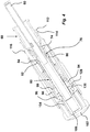
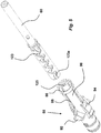
- Figs. 3-4 show a distal part of the device according to Fig. 1 .
- Fig. 3 shows the plunger rod 60 formed as a tube and with an outer diameter somewhat smaller than the inner diameter of the medicament container to be used.
- the recesses 62 of the plunger rod 60 comprise a certain width and depth.
- the drive spring 64 as e.g. a helical compression spring.
- the carrier driver 68 Adjacent the recesses 62 of the plunger rod 60, the carrier driver 68 is arranged.
- the carrier driver comprises a tubularly shaped body 70 with an annular ledge 72 and a number of flexible tongues 74 directed towards the distal end of the device, Fig. 3 .
- Each tongue 74 is arranged with inwardly directed ledges 76, Fig. 4 , arranged and shaped as to fit into the recesses 62 of the plunger rod 60. Further, the ledges 46 of the medicament container carrier 36 pass behind the annular ledge 72 of the carrier driver 68 such that the container carrier and the carrier driver are connected to each other
- the actuator 80 with a mainly tubular shape is coaxially arranged surrounding the plunger rod 62.
- a number of longitudinally directed cut-outs 88 are arranged at the proximal part of the actuator so as to form flexible tongues 90, Figs. 3-5 .
- the proximal end of each flexible tongue 90 has an inclined transition surface 82 which meets with a band-shaped part 84 with enlarged diameter.
- the annular inwardly directed ledge 86 is arranged, with a shape as to fit into the recesses 62 of the plunger rod 60.
- the actuator 80 is further provided with two stop ledges 92 directed radially outwards from the outer surface on either side, Fig. 5 .
- each tongue is arranged with an outwardly directed hook 96 at the outer end and a protrusion 98, with an inclined surface 99, a distance along each tongue, Fig. 4 .
- an annular ring 128 is arranged, which ring is provided with a circumferential ledge 130 with a shape corresponding to the hooks 96 of the actuator.
- the upper end of the actuator is arranged with a transversal end wall 100.
- the actuator button 102 is attached to the upper end of the actuator having two tongues 104 attached and directed in the proximal direction of the device, forming the trigger unit.
- the actuator sleeve 110 is coaxially and slidably arranged on the actuator 80. As seen in Fig. 3 , the actuator sleeve 110 comprises a proximal end with a conical part 112 ending in a ledge 114 on its outer surface. At a distance from the ledge 114, a first annular ring 116 is arranged the outer surface. A second annular ring 118 is also arranged a further distance from the ledge 114. The distal end of the actuator sleeve is arranged with two oppositely arranged cut-outs 120 of a generally rectangular shape where the widths correspond to the width of the stop ledges 92 of the actuator. A compression spring 122, Fig.
- delivery member cover spring surrounds the actuator sleeve 110 and is arranged between the second annular ring 118 of the actuator sleeve and the annular ring 128 on the inner surface of the distal housing.
- two openings 32 are arranged opposite each other, where each opening is arranged with somewhat inwardly projecting tongues.
- the flexible tongues 34 at the openings 32 of the delivery member cover fit into the circumferential recess formed between the first 116 and the second 118 annular rings of the actuator sleeve, such that the delivery member cover and the actuator sleeve form the cover unit.
- the first braking means is at least one groove on the outer surface of the plunger rod and the second braking means is at least one inwardly directed protrusion on the flexible tongues 90 of the actuator 80.
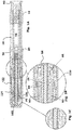
- the first braking means is at least one groove 123 on the outer surface of the plunger rod 60 with alternating groove sections with inclined directions in relation to the longitudinal direction of the plunger rod, i.e. forming a kind of zig-zag pattern, Fig. 5 .
- the second braking means is at least one inwardly directed protrusion 125 on the oppositely positioned tongues 90.
- the at least one inwardly directed protrusion 125 has a shape which fits into the at least one groove 123 of the plunger rod.
- the at least one groove 123 has a pitch that can be modified during manufacturing for modifying the speed of the plunger rod.
- the first braking means is at least one groove 140 made as a helically extending groove on the outer surface of the plunger rod, Fig. 6 .
- the second braking means is at least one inwardly directed protrusion 142 on the oppositely positioned tongues 90.
- the protrusions 142 slide along the side surfaces of the helically extending groove 140 and due to the friction, the speed of the plunger rod is lowered.
- the speed can be changed by changing the pitch of the helical groove 140 in relation to the longitudinal direction.
- the at least one groove 123 of the first embodiment and the helically extending groove 140 of the second embodiment have, at the distal end of the plunger rod, a groove section 123a with a direction generally corresponding with the longitudinal direction of the plunger rod, the function of which will be described below.
- the plunger rod 60 is held against the force of the compression spring by the release mechanism wherein the inwardly directed ledges 86 of the tongues 90 of the actuator are situated in the recesses 62 of the plunger rod 60 and that the actuator sleeve 110 prevents the tongues 90 from moving radially outwards. Further the ledges 76 of the carrier driver are also arranged into the recesses 62. The hooks 96 of the actuator 80 are adjacent the circumferential ledge 130 as a second safety means.
- the needle protection cap grabber When a medicament delivery is to be performed the needle protection cap grabber is pulled out of the device. If the actuator button is depressed, without having depressed the cover unit against a delivery site, the hooks 96 of the actuator 80 will be engaged with the circumferential ledge 130 of the distal housing, and will thereby prevent the inwardly directed ledges 86 of the tongues 90 of the actuator from being released from the recesses 62.
- the distal end of the delivery member cover is in contact with the first annular ring 116 of the actuator sleeve 110 and its movement causes the sleeve to move in the distal direction, whereby a part of the proximal end of the band-shaped part 84 is moved outside the proximal end of the actuator sleeve 110.
- the distally directed edge of the actuator sleeve 110 will then come in contact with the inclined surface 99 of the tongues 94 on the actuator 80 whereby the hooks 96 are moved radially inwards and are free to pass longitudinally inside the circumferential ledge 130.
- the next step is to activate the penetration and dose delivery. Should the user however remove the device from the delivery site the compression spring 122 will push the actuator sleeve 110 and thereby the delivery member cover 20 back to its original position and a press on the button will not cause the device to fire.
- the user merely depresses the actuator button 102. This causes the actuator to be moved in the proximal direction whereby the hooks 96 pass inside the circumferential ledge 130 and the band-shaped part 84 moves completely out of the actuator sleeve.
- the resilient properties of the flexible tongues 90 of the actuator causes the ledges 86 to move out of the groove 62 of the plunger, which then is free to move due to the preloaded spring 64.
- the speed of the plunger rod in the proximal direction is affected by the first and second braking means due to the friction between the protrusions 125 and the side walls of the groove 123 of the plunger rod 60.
- the friction force and thus the speed can be modified by changing the pitch of the groove section in relation to the longitudinal direction.
- the force from the compression spring 64 now moves the stopper inside the medicament container 16 and the liquid medicament is delivered to the patient until the stopper reaches the inner proximal end of the medicament container 16, still under the influence of the first and the second braking means.
- the most proximal groove portion 123a is generally in line with the longitudinal direction of the plunger rod, i.e. there is no braking action at the end of the dose delivery sequence and this is due to that the force of the drive spring decreases when it is expanding during penetration and subsequent dose delivery such that the force at the end of the dose delivery sequence is so low that no braking action is necessary.
- the force of the delivery member cover spring 122 pushes the actuator sleeve 110 and thus the delivery member cover 20 connected to it in the proximal direction, whereby the delivery member cover 20 is pushed out of the proximal end of the device and surrounds the medicament delivery member.
- the movement of the actuator sleeve causes the band-shaped part 84 of the actuator 80 to pass ribs arranged on the inner surface of the actuator sleeve. These ribs prevent any attempts to push the delivery member cover back into the device because the ribs will abut the proximal end of the band-shaped part 84 of the actuator 80. The delivery member cover is thus locked.
Description
- The present invention relates to a medicament delivery device comprising a preloaded drive unit for delivering a dose of medicament and more particularly to a braking mechanism for controlling the speed of the preloaded drive unit.
- There are many medicament delivery devices on the market that can perform a number of functions automatically.
- One such medicament delivery device is disclosed in the document
WO 2005/044348 , which is capable of a penetration sequence, an injection sequence and thereafter a withdrawal sequence when a user has activated the device by first pressing it against an injection site and thereafter pressing an actuation button. - A medicament delivery device according to the preamble of claim 1 is known from document
WO 2009/105908 A1 . - The device has proven very successful and is on the market for a number of different drugs for treatment of different diseases. The device uses a drive spring for both the penetration sequence as well as the subsequent injection sequence. For some drugs it is desirable that the spring is as weak as possible in order that the sequences shall not be performed too fast and at the same time ensure that the medicament container is properly emptied, i.e. that the stopper is moved to the proximal end position inside the medicament container. Even so, it has been found that the injection sequence preferably should be performed even slower in order not to cause pain and discomfort to the user. There is thus room for improvements of an otherwise well functioning medicament delivery device.
- The aim of the present invention is to remedy the drawbacks of the state of the art devices.
- This aim is obtained by a medicament delivery device according to the features of the independent patent claim.
- Preferable embodiments of the invention form the subject of the dependent patent claims.
- According to a main aspect of the invention it is characterised by a medicament delivery device that comprises an elongated housing; a medicament container carrier adapted to house a medicament container to which a medicament delivery member is attached and wherein the carrier is slidably accommodated within the housing; a trigger unit; a cover unit coaxially and slidably arranged within the housing; a release mechanism adapted to be partly actuated by the operation of the trigger unit and partly actuated by the movement of the cover unit; a preloaded drive unit releasably connected to the medicament container carrier and controlled by the release mechanism for advancing firstly the medicament container carrier to a predetermined proximal position in relation to the housing and upon the carrier reaching the predetermined proximal position, the drive unit becomes disconnected from the carrier for advancing a slidable stopper within the container and thereby dispensing the medicament; and a braking mechanism acting between the preloaded drive unit and the release mechanism for controlling the speed of the preloaded drive unit when advancing the slidable stopper within the container.
- According to another aspect of the invention, the preloaded drive unit comprises a drive spring and a plunger rod.
- According to yet another aspect of the invention, the braking mechanism comprises first braking means on the outer surface of the plunger rod and second braking means of the release mechanism interactively connected to each other by a non-positive connection.
- According to a further aspect of the invention, the trigger unit comprises an actuator button and an actuator connected to each other.
- According to yet a further aspect of the invention, the cover unit comprises a delivery member cover and an actuator sleeve connected to each other, wherein the actuator sleeve is coaxially and slidably arranged on the actuator.
- According to another aspect of the invention, the release mechanism comprises annular inwardly directed ledges on flexible tongues of the actuator, and recesses on the outer surface of the plunger rod arranged to be engaged with each other for holding the drive unit in a preloaded state in which the drive unit is connected to the carrier by a carrier driver.
- According to yet another aspect of the invention, the first braking means is at least one groove on the outer surface of the plunger rod and wherein the second braking means is at least one inwardly directed protrusion on the flexible tongues of the actuator.
- According to a further aspect of the invention, said at least one groove comprise a number of sections forming a zig-zag shape.
- According to yet a further aspect of the invention, said at least one groove has a helical extension around said plunger rod.
- According to another aspect of the invention, said at least one groove has a pitch that can be modified during manufacturing for modifying the speed of the plunger rod.
- According to yet another aspect of the invention, a section of said at least one groove at the proximal end of said plunger rod has a direction generally parallel with the longitudinal direction of the plunger rod.
- There are several advantages with the present invention. Because of the plunger rod brake it is possible to use stronger drive springs without the drawback that the dose delivery is performed very fast, which otherwise would be the case with stronger drive springs. Thereby it is ascertained that the medicament container is properly emptied. Further the control of the speed of the plunger rod is acting directly on the plunger rod by the at least one protrusion acting in the at least one groove. Thus a very efficient yet simple design is obtained. It is also rather easy to change the speed of the plunger rod by altering the pitch of the at least one groove. Since the force of the drive spring is low at the end of the injection sequence no braking action is needed and thus the most proximal groove section is preferably generally parallel with the extension of the plunger rod.
- These and other aspects and advantages of, the present invention will become apparent from the following detailed description of the invention and from the accompanying drawings.
- In the following detailed description of the invention, reference will be made to the accompanying drawings, of which
- Fig. 1
- is a cross-sectional view of a medicament delivery device according to the present invention,
- Fig. 2
- is an exploded view of a proximal part of the device of
Fig. 1 , - Fig. 3
- is an exploded view of a distal part of the device of
Fig. 1 , - Fig. 4
- is a cross-sectional view of the distal part of the device of
Fig. 1 , - Fig. 5
- is a detailed view of one embodiment of the braking mechanism, and
- Fig. 6
- is a detailed view of another embodiment of the braking mechanism.
- In the present application, when the term "distal part/end" is used, this refers to the part/end of the medicament delivery device, or the parts/ends of the members thereof, which under use of the medicament delivery device is located the furthest away from the medicament delivery site of the patient. Correspondingly, when the term "proximal part/end" is used, this refers to the part/end of the medicament delivery device, or the parts/ends of the members thereof, which under use of the medicament delivery device is located closest to the medicament delivery site of the patient.
- According to a main aspect of the invention, the medicament delivery device comprises an elongated housing; a
medicament container carrier 36 adapted to house amedicament container 16 to which a medicament delivery member is attached and wherein the carrier is slidably accommodated within the housing; a trigger unit; a cover unit coaxially and slidably arranged within the housing; a release mechanism adapted to be partly actuated by the operation of the trigger unit and partly actuated by the movement of the cover unit; a preloaded drive unit releasably connected to the medicament container carrier and controlled by the release mechanism for advancing firstly the medicament container carrier to a predetermined proximal position in relation to the housing and upon the carrier reaching the predetermined proximal position, the drive unit becomes disconnected from the carrier for advancing a slidable stopper within the container and thereby dispensing the medicament; and a braking mechanism acting between the preloaded drive unit and the release mechanism for controlling the speed of the preloaded drive unit when advancing the slidable stopper within the container. - The preloaded drive unit comprises a
drive spring 64 and aplunger rod 60. The braking mechanism comprises first braking means on the outer surface of the plunger rod and second braking means of the release mechanism interactively connected to each other by a non-positive connection. The trigger unit comprises anactuator button 102 and anactuator 80 connected to each other. The cover unit comprises adelivery member cover 20 and anactuator sleeve 110 connected to each other, wherein the actuator sleeve is coaxially and slidably arranged on theactuator 80. The release mechanism comprises annular inwardly directedledges 86 onflexible tongues 90 of theactuator 80, and recesses 62 on the outer surface of theplunger rod 60 arranged to be engaged with each other for holding the drive unit in a preloaded state in which the drive unit is connected to the carrier by acarrier driver 68. - The
figures1-6 show exemplary embodiments of a medicament delivery device according to the present invention. - The device shown in
Fig. 1 comprises an elongated housing formed by a generally tubularproximal housing 12 and adistal housing 124 of a generally tubular shape, but not restricted to it. The proximal housing compriseselongated openings 14 for viewing amedicament container 16,Fig. 1 , and a somewhat narrowing proximal end. The shownmedicament container 16 is a syringe with a medicament delivery member in the form of an integrated injection needle. It is however to be understood that other types of medicament containers may be employed within the scope of the present invention as well as other types of medicament delivery members such as mouth or nose pieces, nozzles, nebulizers and the like. - The distal end of the
proximal housing 12 is arranged with annular recesses 18 on the inner surface. The proximal end of the distal housing has a somewhat lesser outer diameter, corresponding to the inner diameter of the distal end of the proximal housing and provided with a number ofannular protrusions 126 which are intended to fit into the corresponding annular recesses 18 on the inner surface of theproximal housing 12. Inside the elongated housing the cover unit is slidably arranged. Thedelivery member cover 20 is generally tubular with a first proximal part 22 having a certain diameter and a second distal part 24 having a diameter larger than the proximal part 22, where these parts are joined by an intermediateconical part 26,Fig. 2 . Two oppositeelongated grooves 28 are arranged along the delivery member cover for viewing the medicament container. On the inner surface of the conical part a circumferential ledge 30 is arranged. At the circumferential distal end of the delivery member cover twoopenings 32 are arranged opposite each other, where each opening is arranged with somewhat inwardly projecting, flexible, tongues 34. - Further, the
medicament container carrier 36 is arranged inside the delivery member cover in the form of a generally tubular body. The proximal part of themedicament container carrier 36 is arranged with a neck portion 38 of lesser diameter. Adjacent the neck portion cut-outs 40 have been made on either side to form guide surfaces. These surfaces cooperate with corresponding shapes of the inner surface of thedelivery member cover 20 in order to obtain a stop means against rotation of themedicament container carrier 36 relative the delivery member cover. The distal end of the medicament container carrier is arranged with two distally directed tongues 42 where each tongue is arranged with an opening 44 and an inwardly directed ledge 46 on the distal edge of each opening. The medicament container carrier is further arranged with radially directed flanges 48 on its inner surface in order to obtain a space between the medicament container carrier inner wall and the medicament container to be placed inside. - At the proximal end of the proximal part of the delivery member cover, a needle
protection cap grabber 50 is arranged. It is inserted into the proximal part of the delivery member cover and held there by friction. Inside the cap grabber a metal ring 52 is arranged with sharp pointed tongues 54 directed somewhat inwards and towards the proximal end. -
Figs. 3-4 show a distal part of the device according toFig. 1 .Fig. 3 shows theplunger rod 60 formed as a tube and with an outer diameter somewhat smaller than the inner diameter of the medicament container to be used. Therecesses 62 of theplunger rod 60 comprise a certain width and depth. Inside theplunger rod 60 is arranged thedrive spring 64 as e.g. a helical compression spring. Adjacent therecesses 62 of theplunger rod 60, thecarrier driver 68 is arranged. The carrier driver comprises a tubularly shapedbody 70 with anannular ledge 72 and a number offlexible tongues 74 directed towards the distal end of the device,Fig. 3 . Eachtongue 74 is arranged with inwardly directedledges 76,Fig. 4 , arranged and shaped as to fit into therecesses 62 of theplunger rod 60. Further, the ledges 46 of themedicament container carrier 36 pass behind theannular ledge 72 of thecarrier driver 68 such that the container carrier and the carrier driver are connected to each other - As seen in
Fig. 4 , theactuator 80 with a mainly tubular shape is coaxially arranged surrounding theplunger rod 62. A number of longitudinally directed cut-outs 88 are arranged at the proximal part of the actuator so as to formflexible tongues 90,Figs. 3-5 . The proximal end of eachflexible tongue 90 has aninclined transition surface 82 which meets with a band-shapedpart 84 with enlarged diameter. On the inner surface adjacent eachtransition surface 82, the annular inwardly directedledge 86 is arranged, with a shape as to fit into therecesses 62 of theplunger rod 60. Theactuator 80 is further provided with twostop ledges 92 directed radially outwards from the outer surface on either side,Fig. 5 . Between the stop ledges twoflexible tongues 94 are arranged on the outer surface. Each tongue is arranged with an outwardly directedhook 96 at the outer end and aprotrusion 98, with aninclined surface 99, a distance along each tongue,Fig. 4 . On the inner circumferential surface of the distal housing, anannular ring 128 is arranged, which ring is provided with acircumferential ledge 130 with a shape corresponding to thehooks 96 of the actuator. The upper end of the actuator is arranged with atransversal end wall 100. Theactuator button 102 is attached to the upper end of the actuator having twotongues 104 attached and directed in the proximal direction of the device, forming the trigger unit. - The
actuator sleeve 110 is coaxially and slidably arranged on theactuator 80. As seen inFig. 3 , theactuator sleeve 110 comprises a proximal end with aconical part 112 ending in aledge 114 on its outer surface. At a distance from theledge 114, a firstannular ring 116 is arranged the outer surface. A secondannular ring 118 is also arranged a further distance from theledge 114. The distal end of the actuator sleeve is arranged with two oppositely arranged cut-outs 120 of a generally rectangular shape where the widths correspond to the width of the stop ledges 92 of the actuator. Acompression spring 122,Fig. 1a , hereafter named delivery member cover spring surrounds theactuator sleeve 110 and is arranged between the secondannular ring 118 of the actuator sleeve and theannular ring 128 on the inner surface of the distal housing. At the circumferential distal end of the delivery member cover twoopenings 32 are arranged opposite each other, where each opening is arranged with somewhat inwardly projecting tongues. The flexible tongues 34 at theopenings 32 of the delivery member cover fit into the circumferential recess formed between the first 116 and the second 118 annular rings of the actuator sleeve, such that the delivery member cover and the actuator sleeve form the cover unit. - According to the invention, the first braking means is at least one groove on the outer surface of the plunger rod and the second braking means is at least one inwardly directed protrusion on the
flexible tongues 90 of theactuator 80. - According to a first embodiment, the first braking means is at least one
groove 123 on the outer surface of theplunger rod 60 with alternating groove sections with inclined directions in relation to the longitudinal direction of the plunger rod, i.e. forming a kind of zig-zag pattern,Fig. 5 . Further, according the first embodiment, the second braking means is at least one inwardly directedprotrusion 125 on the oppositely positionedtongues 90. The at least one inwardly directedprotrusion 125 has a shape which fits into the at least onegroove 123 of the plunger rod. The at least onegroove 123 has a pitch that can be modified during manufacturing for modifying the speed of the plunger rod. - According to a second embodiment, the first braking means is at least one
groove 140 made as a helically extending groove on the outer surface of the plunger rod,Fig. 6 . As with the previous embodiment, the second braking means is at least one inwardly directedprotrusion 142 on the oppositely positionedtongues 90. When the plunger rod now moves in the proximal direction during medicament delivery, theprotrusions 142 slide along the side surfaces of thehelically extending groove 140 and due to the friction, the speed of the plunger rod is lowered. As with the previous embodiment, the speed can be changed by changing the pitch of thehelical groove 140 in relation to the longitudinal direction. - Further, the at least one
groove 123 of the first embodiment and the helically extendinggroove 140 of the second embodiment have, at the distal end of the plunger rod, agroove section 123a with a direction generally corresponding with the longitudinal direction of the plunger rod, the function of which will be described below. - The
plunger rod 60 is held against the force of the compression spring by the release mechanism wherein the inwardly directedledges 86 of thetongues 90 of the actuator are situated in therecesses 62 of theplunger rod 60 and that theactuator sleeve 110 prevents thetongues 90 from moving radially outwards. Further theledges 76 of the carrier driver are also arranged into therecesses 62. Thehooks 96 of theactuator 80 are adjacent thecircumferential ledge 130 as a second safety means. - When a medicament delivery is to be performed the needle protection cap grabber is pulled out of the device. If the actuator button is depressed, without having depressed the cover unit against a delivery site, the
hooks 96 of theactuator 80 will be engaged with thecircumferential ledge 130 of the distal housing, and will thereby prevent the inwardly directedledges 86 of thetongues 90 of the actuator from being released from therecesses 62. However, when the proximal end of the cover unit is pressed against a dose delivery site against the force of thecompression spring 122, the distal end of the delivery member cover is in contact with the firstannular ring 116 of theactuator sleeve 110 and its movement causes the sleeve to move in the distal direction, whereby a part of the proximal end of the band-shapedpart 84 is moved outside the proximal end of theactuator sleeve 110. The distally directed edge of theactuator sleeve 110 will then come in contact with theinclined surface 99 of thetongues 94 on theactuator 80 whereby thehooks 96 are moved radially inwards and are free to pass longitudinally inside thecircumferential ledge 130. - The next step is to activate the penetration and dose delivery. Should the user however remove the device from the delivery site the
compression spring 122 will push theactuator sleeve 110 and thereby thedelivery member cover 20 back to its original position and a press on the button will not cause the device to fire. When activating the penetration and dose delivery, the user merely depresses theactuator button 102. This causes the actuator to be moved in the proximal direction whereby thehooks 96 pass inside thecircumferential ledge 130 and the band-shapedpart 84 moves completely out of the actuator sleeve. The resilient properties of theflexible tongues 90 of the actuator causes theledges 86 to move out of thegroove 62 of the plunger, which then is free to move due to thepreloaded spring 64. The penetration stops when the proximal surface of themedicament container carrier 36 abuts the circumferential ledge 30 of the delivery member cover and theledges 76 of thecarrier driver 68 are also moved out of thegroove 62 because thearms 74 of the carrier driver are no longer held in place by the band-shaped part of the actuator. I.e. the plunger rod is disconnected from the container carrier and starts to act on the stopper. - However the speed of the plunger rod in the proximal direction is affected by the first and second braking means due to the friction between the
protrusions 125 and the side walls of thegroove 123 of theplunger rod 60. In this context it is to be understood that the friction force and thus the speed can be modified by changing the pitch of the groove section in relation to the longitudinal direction. - The force from the
compression spring 64 now moves the stopper inside themedicament container 16 and the liquid medicament is delivered to the patient until the stopper reaches the inner proximal end of themedicament container 16, still under the influence of the first and the second braking means. However, preferably the mostproximal groove portion 123a is generally in line with the longitudinal direction of the plunger rod, i.e. there is no braking action at the end of the dose delivery sequence and this is due to that the force of the drive spring decreases when it is expanding during penetration and subsequent dose delivery such that the force at the end of the dose delivery sequence is so low that no braking action is necessary. - When the
plunger rod 60 has moved the stopper to the proximal end of the medicament container, its distal end has passed theledges 86 of theactuator 80 and thetongues 90 are moved inwards. Because thecompression spring 64 is also acting on theactuator 80, theactuator 80 is moved inside theactuator sleeve 110. Because of this and because the deliverymember cover spring 122 is acting on theactuator sleeve 110 it is urged in the proximal direction. When now the device is removed from the medicament delivery site, the force of the deliverymember cover spring 122 pushes theactuator sleeve 110 and thus thedelivery member cover 20 connected to it in the proximal direction, whereby thedelivery member cover 20 is pushed out of the proximal end of the device and surrounds the medicament delivery member. The movement of the actuator sleeve causes the band-shapedpart 84 of theactuator 80 to pass ribs arranged on the inner surface of the actuator sleeve. These ribs prevent any attempts to push the delivery member cover back into the device because the ribs will abut the proximal end of the band-shapedpart 84 of theactuator 80. The delivery member cover is thus locked. - It is to be understood that the embodiment described above and shown in the drawings is to be regarded only as a non-limiting example of the invention and that it may be modified in many ways within the scope of the patent claims.
Claims (7)
- A medicament delivery device comprising:- an elongated housing (12, 124);- a medicament container carrier (36) adapted to house a medicament container (16) to which a medicament delivery member is attached and wherein the carrier is slidably accommodated within the housing;- a trigger unit comprising an actuator button (102) and an actuator (80) connected to each other;- a cover unit coaxially and slidably arranged within the housing wherein the cover unit comprises a delivery member cover (20) and an actuator sleeve (110) connected to each other, wherein the actuator sleeve is coaxially and slidably arranged on the actuator (80);- a release mechanism adapted to be partly actuated by the operation of the trigger unit and partly actuated by the movement of the cover unit;- a preloaded drive unit releasably connected to the medicament container carrier (36) and controlled by the release mechanism for advancing firstly the medicament container carrier to a predetermined proximal position in relation to the housing and upon the carrier reaching the predetermined proximal position, the drive unit becomes disconnected from the carrier for advancing a slidable stopper within the container and thereby dispensing the medicament, and wherein the preloaded drive unit comprises a drive spring (64) and a plunger rod (60); characterised in thatthe device further comprises a braking mechanism acting between the preloaded drive unit and the release mechanism for controlling the speed of the preloaded drive unit when advancing the slidable stopper within the container, and wherein the braking mechanism comprises first braking means on the outer surface of the plunger rod and second braking means of the release mechanism interactively connected to each other by a non-positive connection.
- Medicament delivery device according to claim 1, wherein the release mechanism comprises annular inwardly directed ledges (86) on flexible tongues (90) of the actuator (80), and recesses (62) on the outer surface of the plunger rod (60) arranged to be engaged with each other for holding the drive unit in a preloaded state in which the drive unit is connected to the carrier by a carrier driver (68).
- Medicament delivery device according to claim 2, wherein the first braking means is at least one groove (123; 140) on the outer surface of the plunger rod and wherein the second braking means is at least one inwardly directed protrusion (125; 142) on the flexible tongues (90) of the actuator (80).
- Medicament delivery device according to claim 3, wherein said at least one groove (123) comprises a number of sections forming a zig-zag shape.
- Medicament delivery device according to claim 3, wherein said at least one groove (140) has a helical extension around said plunger rod.
- Medicament delivery device according to claim 4 or 5, wherein said at least one groove (123; 140) has a pitch that can be modified during manufacturing for modifying the speed of the plunger rod.
- Medicament delivery device according to claim 6, wherein a section of said at least one groove at the proximal end of said plunger rod has a direction (123a) generally parallel with the longitudinal direction of the plunger rod.
Applications Claiming Priority (3)
| Application Number | Priority Date | Filing Date | Title |
|---|---|---|---|
| US35809310P | 2010-06-24 | 2010-06-24 | |
| SE1050692 | 2010-06-24 | ||
| PCT/SE2011/050775 WO2011162686A1 (en) | 2010-06-24 | 2011-06-17 | Medicament delivery device with braking means |
Publications (3)
| Publication Number | Publication Date |
|---|---|
| EP2585143A1 EP2585143A1 (en) | 2013-05-01 |
| EP2585143A4 EP2585143A4 (en) | 2017-11-29 |
| EP2585143B1 true EP2585143B1 (en) | 2018-12-12 |
Family
ID=45371661
Family Applications (1)
| Application Number | Title | Priority Date | Filing Date |
|---|---|---|---|
| EP11798456.7A Active EP2585143B1 (en) | 2010-06-24 | 2011-06-17 | Medicament delivery device with braking means |
Country Status (3)
| Country | Link |
|---|---|
| US (1) | US9248236B2 (en) |
| EP (1) | EP2585143B1 (en) |
| WO (1) | WO2011162686A1 (en) |
Families Citing this family (18)
| Publication number | Priority date | Publication date | Assignee | Title |
|---|---|---|---|---|
| GB2467904B (en) * | 2009-02-17 | 2013-06-12 | Oval Medical Technologies Ltd | Drug container and delivery mechanism |
| US9468723B2 (en) | 2010-06-24 | 2016-10-18 | Shl Group Ab | Medicament delivery device |
| GB2519971B (en) * | 2013-11-01 | 2017-06-14 | Consort Medical Plc | Medicament delivery device sub-assembly |
| WO2015073740A2 (en) * | 2013-11-13 | 2015-05-21 | Genentech, Inc. | Assisted manual injector devices and methods |
| EP3068467B1 (en) | 2013-11-15 | 2019-05-15 | SHL Medical AG | Medicament delivery device |
| KR101892834B1 (en) * | 2014-02-14 | 2018-08-28 | 케어베이 유럽 리미티드 | Automatic injection device |
| US10307543B2 (en) | 2014-10-09 | 2019-06-04 | Shl Medical Ag | Power pack assembly for a medicament delivery device |
| GB2538566B (en) | 2015-05-22 | 2020-09-30 | Owen Mumford Ltd | Injection device |
| GB2541915A (en) * | 2015-09-03 | 2017-03-08 | Owen Mumford Ltd | Medicament delivery devices |
| FR3046079B1 (en) * | 2015-12-24 | 2022-02-25 | Nemera La Verpilliere | AUTOMATIC INJECTION DEVICE WITH IMPROVED CAM WAY. |
| US11107369B2 (en) * | 2016-03-07 | 2021-08-31 | Shl Medical Ag | Automatic injection training device |
| GB201616709D0 (en) | 2016-09-30 | 2016-11-16 | Owen Mumford Ltd | Injection device |
| US11376364B2 (en) | 2017-03-15 | 2022-07-05 | Owen Mumford Limited | Injection apparatus |
| GB201704140D0 (en) | 2017-03-15 | 2017-04-26 | Owen Mumford Ltd | Injection device with velocity regulator |
| GB2560555A (en) | 2017-03-15 | 2018-09-19 | Owen Mumford Ltd | Injection device with deliver phase velocity regulator |
| GB201715237D0 (en) * | 2017-09-21 | 2017-11-08 | Shore Product Group Ltd | Training device |
| JP6959452B2 (en) * | 2018-01-09 | 2021-11-02 | エスエイチエル・メディカル・アーゲー | Support structure |
| EP4126120A1 (en) * | 2020-04-03 | 2023-02-08 | Sanofi | Injector device having a braking arrangement |
Family Cites Families (8)
| Publication number | Priority date | Publication date | Assignee | Title |
|---|---|---|---|---|
| US7329239B2 (en) * | 1997-02-05 | 2008-02-12 | Medtronic Minimed, Inc. | Insertion device for an insertion set and method of using the same |
| US7569035B1 (en) * | 2001-11-02 | 2009-08-04 | Meridian Medical Technologies, Inc. | Automatic injector with anti-coring needle |
| TWI314464B (en) * | 2002-06-24 | 2009-09-11 | Alza Corp | Reusable, spring driven autoinjector |
| US9486581B2 (en) * | 2002-09-11 | 2016-11-08 | Becton, Dickinson And Company | Injector device with force lock-out and injection rate limiting mechanisms |
| US20050101919A1 (en) | 2003-11-07 | 2005-05-12 | Lennart Brunnberg | Device for an injector |
| GB2443390A (en) * | 2006-11-03 | 2008-05-07 | Owen Mumford Ltd | Medicine delivery apparatus |
| DE102008011881A1 (en) | 2008-02-29 | 2009-09-10 | Tecpharma Licensing Ag | Empty shooting speed limit brake |
| WO2011032731A1 (en) * | 2009-09-21 | 2011-03-24 | Tecpharma Licensing Ag | Damping the piston rod for partially filled syringes |
-
2011
- 2011-06-17 WO PCT/SE2011/050775 patent/WO2011162686A1/en active Application Filing
- 2011-06-17 EP EP11798456.7A patent/EP2585143B1/en active Active
- 2011-06-17 US US13/806,779 patent/US9248236B2/en active Active
Non-Patent Citations (1)
| Title |
|---|
| None * |
Also Published As
| Publication number | Publication date |
|---|---|
| EP2585143A1 (en) | 2013-05-01 |
| US20130102971A1 (en) | 2013-04-25 |
| WO2011162686A1 (en) | 2011-12-29 |
| EP2585143A4 (en) | 2017-11-29 |
| US9248236B2 (en) | 2016-02-02 |
Similar Documents
| Publication | Publication Date | Title |
|---|---|---|
| EP2585143B1 (en) | Medicament delivery device with braking means | |
| US20220362470A1 (en) | Medicament delivery device | |
| EP3011989B1 (en) | Injection device | |
| EP2296732B1 (en) | Medicament delivery device | |
| EP3618903B1 (en) | Needle shield remover | |
| US9468723B2 (en) | Medicament delivery device | |
| EP3104909B1 (en) | Automatic injection device | |
| EP3287162A1 (en) | Autoinjector with audible indication of completed delivery | |
| TWI581815B (en) | Medicament delivery device | |
| EP3204072B1 (en) | A power pack assembly for a medicament delivery device | |
| EP3452146B1 (en) | Drive assembly for a medicament delivery device | |
| EP3568177B1 (en) | Medicament delivery device | |
| EP3316929B1 (en) | Medicament delivery device | |
| EP3655071B1 (en) | Assisted injection device for selectively injecting a composition contained in a medical container | |
| EP3380156B1 (en) | Medicament delivery device |
Legal Events
| Date | Code | Title | Description |
|---|---|---|---|
| PUAI | Public reference made under article 153(3) epc to a published international application that has entered the european phase |
Free format text: ORIGINAL CODE: 0009012 |
|
| 17P | Request for examination filed |
Effective date: 20121228 |
|
| AK | Designated contracting states |
Kind code of ref document: A1 Designated state(s): AL AT BE BG CH CY CZ DE DK EE ES FI FR GB GR HR HU IE IS IT LI LT LU LV MC MK MT NL NO PL PT RO RS SE SI SK SM TR |
|
| RAP1 | Party data changed (applicant data changed or rights of an application transferred) |
Owner name: SHL GROUP AB |
|
| RA4 | Supplementary search report drawn up and despatched (corrected) |
Effective date: 20171026 |
|
| RIC1 | Information provided on ipc code assigned before grant |
Ipc: A61M 5/315 20060101ALI20171020BHEP Ipc: A61M 5/20 20060101AFI20171020BHEP |
|
| GRAP | Despatch of communication of intention to grant a patent |
Free format text: ORIGINAL CODE: EPIDOSNIGR1 |
|
| STAA | Information on the status of an ep patent application or granted ep patent |
Free format text: STATUS: GRANT OF PATENT IS INTENDED |
|
| INTG | Intention to grant announced |
Effective date: 20180725 |
|
| GRAS | Grant fee paid |
Free format text: ORIGINAL CODE: EPIDOSNIGR3 |
|
| GRAA | (expected) grant |
Free format text: ORIGINAL CODE: 0009210 |
|
| STAA | Information on the status of an ep patent application or granted ep patent |
Free format text: STATUS: THE PATENT HAS BEEN GRANTED |
|
| AK | Designated contracting states |
Kind code of ref document: B1 Designated state(s): AL AT BE BG CH CY CZ DE DK EE ES FI FR GB GR HR HU IE IS IT LI LT LU LV MC MK MT NL NO PL PT RO RS SE SI SK SM TR |
|
| REG | Reference to a national code |
Ref country code: GB Ref legal event code: FG4D |
|
| REG | Reference to a national code |
Ref country code: CH Ref legal event code: EP |
|
| REG | Reference to a national code |
Ref country code: AT Ref legal event code: REF Ref document number: 1075132 Country of ref document: AT Kind code of ref document: T Effective date: 20181215 |
|
| REG | Reference to a national code |
Ref country code: DE Ref legal event code: R096 Ref document number: 602011054801 Country of ref document: DE |
|
| REG | Reference to a national code |
Ref country code: IE Ref legal event code: FG4D |
|
| REG | Reference to a national code |
Ref country code: CH Ref legal event code: PUE Owner name: SHL MEDICAL AG, CH Free format text: FORMER OWNER: SHL GROUP AB, SE |
|
| REG | Reference to a national code |
Ref country code: NL Ref legal event code: MP Effective date: 20181212 |
|
| REG | Reference to a national code |
Ref country code: LT Ref legal event code: MG4D |
|
| PG25 | Lapsed in a contracting state [announced via postgrant information from national office to epo] |
Ref country code: LV Free format text: LAPSE BECAUSE OF FAILURE TO SUBMIT A TRANSLATION OF THE DESCRIPTION OR TO PAY THE FEE WITHIN THE PRESCRIBED TIME-LIMIT Effective date: 20181212 Ref country code: NO Free format text: LAPSE BECAUSE OF FAILURE TO SUBMIT A TRANSLATION OF THE DESCRIPTION OR TO PAY THE FEE WITHIN THE PRESCRIBED TIME-LIMIT Effective date: 20190312 Ref country code: FI Free format text: LAPSE BECAUSE OF FAILURE TO SUBMIT A TRANSLATION OF THE DESCRIPTION OR TO PAY THE FEE WITHIN THE PRESCRIBED TIME-LIMIT Effective date: 20181212 Ref country code: LT Free format text: LAPSE BECAUSE OF FAILURE TO SUBMIT A TRANSLATION OF THE DESCRIPTION OR TO PAY THE FEE WITHIN THE PRESCRIBED TIME-LIMIT Effective date: 20181212 Ref country code: HR Free format text: LAPSE BECAUSE OF FAILURE TO SUBMIT A TRANSLATION OF THE DESCRIPTION OR TO PAY THE FEE WITHIN THE PRESCRIBED TIME-LIMIT Effective date: 20181212 Ref country code: ES Free format text: LAPSE BECAUSE OF FAILURE TO SUBMIT A TRANSLATION OF THE DESCRIPTION OR TO PAY THE FEE WITHIN THE PRESCRIBED TIME-LIMIT Effective date: 20181212 Ref country code: BG Free format text: LAPSE BECAUSE OF FAILURE TO SUBMIT A TRANSLATION OF THE DESCRIPTION OR TO PAY THE FEE WITHIN THE PRESCRIBED TIME-LIMIT Effective date: 20190312 |
|
| REG | Reference to a national code |
Ref country code: AT Ref legal event code: MK05 Ref document number: 1075132 Country of ref document: AT Kind code of ref document: T Effective date: 20181212 |
|
| PG25 | Lapsed in a contracting state [announced via postgrant information from national office to epo] |
Ref country code: GR Free format text: LAPSE BECAUSE OF FAILURE TO SUBMIT A TRANSLATION OF THE DESCRIPTION OR TO PAY THE FEE WITHIN THE PRESCRIBED TIME-LIMIT Effective date: 20190313 Ref country code: SE Free format text: LAPSE BECAUSE OF FAILURE TO SUBMIT A TRANSLATION OF THE DESCRIPTION OR TO PAY THE FEE WITHIN THE PRESCRIBED TIME-LIMIT Effective date: 20181212 Ref country code: AL Free format text: LAPSE BECAUSE OF FAILURE TO SUBMIT A TRANSLATION OF THE DESCRIPTION OR TO PAY THE FEE WITHIN THE PRESCRIBED TIME-LIMIT Effective date: 20181212 Ref country code: RS Free format text: LAPSE BECAUSE OF FAILURE TO SUBMIT A TRANSLATION OF THE DESCRIPTION OR TO PAY THE FEE WITHIN THE PRESCRIBED TIME-LIMIT Effective date: 20181212 |
|
| REG | Reference to a national code |
Ref country code: DE Ref legal event code: R081 Ref document number: 602011054801 Country of ref document: DE Owner name: SHL MEDICAL AG, CH Free format text: FORMER OWNER: SHL GROUP AB, NACKA STRAND, SE |
|
| PG25 | Lapsed in a contracting state [announced via postgrant information from national office to epo] |
Ref country code: NL Free format text: LAPSE BECAUSE OF FAILURE TO SUBMIT A TRANSLATION OF THE DESCRIPTION OR TO PAY THE FEE WITHIN THE PRESCRIBED TIME-LIMIT Effective date: 20181212 |
|
| PG25 | Lapsed in a contracting state [announced via postgrant information from national office to epo] |
Ref country code: PL Free format text: LAPSE BECAUSE OF FAILURE TO SUBMIT A TRANSLATION OF THE DESCRIPTION OR TO PAY THE FEE WITHIN THE PRESCRIBED TIME-LIMIT Effective date: 20181212 Ref country code: IT Free format text: LAPSE BECAUSE OF FAILURE TO SUBMIT A TRANSLATION OF THE DESCRIPTION OR TO PAY THE FEE WITHIN THE PRESCRIBED TIME-LIMIT Effective date: 20181212 Ref country code: CZ Free format text: LAPSE BECAUSE OF FAILURE TO SUBMIT A TRANSLATION OF THE DESCRIPTION OR TO PAY THE FEE WITHIN THE PRESCRIBED TIME-LIMIT Effective date: 20181212 Ref country code: PT Free format text: LAPSE BECAUSE OF FAILURE TO SUBMIT A TRANSLATION OF THE DESCRIPTION OR TO PAY THE FEE WITHIN THE PRESCRIBED TIME-LIMIT Effective date: 20190412 |
|
| REG | Reference to a national code |
Ref country code: GB Ref legal event code: 732E Free format text: REGISTERED BETWEEN 20190801 AND 20190807 |
|
| PG25 | Lapsed in a contracting state [announced via postgrant information from national office to epo] |
Ref country code: SK Free format text: LAPSE BECAUSE OF FAILURE TO SUBMIT A TRANSLATION OF THE DESCRIPTION OR TO PAY THE FEE WITHIN THE PRESCRIBED TIME-LIMIT Effective date: 20181212 Ref country code: IS Free format text: LAPSE BECAUSE OF FAILURE TO SUBMIT A TRANSLATION OF THE DESCRIPTION OR TO PAY THE FEE WITHIN THE PRESCRIBED TIME-LIMIT Effective date: 20190412 Ref country code: RO Free format text: LAPSE BECAUSE OF FAILURE TO SUBMIT A TRANSLATION OF THE DESCRIPTION OR TO PAY THE FEE WITHIN THE PRESCRIBED TIME-LIMIT Effective date: 20181212 Ref country code: EE Free format text: LAPSE BECAUSE OF FAILURE TO SUBMIT A TRANSLATION OF THE DESCRIPTION OR TO PAY THE FEE WITHIN THE PRESCRIBED TIME-LIMIT Effective date: 20181212 Ref country code: SM Free format text: LAPSE BECAUSE OF FAILURE TO SUBMIT A TRANSLATION OF THE DESCRIPTION OR TO PAY THE FEE WITHIN THE PRESCRIBED TIME-LIMIT Effective date: 20181212 |
|
| REG | Reference to a national code |
Ref country code: DE Ref legal event code: R097 Ref document number: 602011054801 Country of ref document: DE |
|
| PLBE | No opposition filed within time limit |
Free format text: ORIGINAL CODE: 0009261 |
|
| STAA | Information on the status of an ep patent application or granted ep patent |
Free format text: STATUS: NO OPPOSITION FILED WITHIN TIME LIMIT |
|
| PG25 | Lapsed in a contracting state [announced via postgrant information from national office to epo] |
Ref country code: SI Free format text: LAPSE BECAUSE OF FAILURE TO SUBMIT A TRANSLATION OF THE DESCRIPTION OR TO PAY THE FEE WITHIN THE PRESCRIBED TIME-LIMIT Effective date: 20181212 Ref country code: DK Free format text: LAPSE BECAUSE OF FAILURE TO SUBMIT A TRANSLATION OF THE DESCRIPTION OR TO PAY THE FEE WITHIN THE PRESCRIBED TIME-LIMIT Effective date: 20181212 Ref country code: AT Free format text: LAPSE BECAUSE OF FAILURE TO SUBMIT A TRANSLATION OF THE DESCRIPTION OR TO PAY THE FEE WITHIN THE PRESCRIBED TIME-LIMIT Effective date: 20181212 |
|
| 26N | No opposition filed |
Effective date: 20190913 |
|
| PG25 | Lapsed in a contracting state [announced via postgrant information from national office to epo] |
Ref country code: MC Free format text: LAPSE BECAUSE OF FAILURE TO SUBMIT A TRANSLATION OF THE DESCRIPTION OR TO PAY THE FEE WITHIN THE PRESCRIBED TIME-LIMIT Effective date: 20181212 |
|
| REG | Reference to a national code |
Ref country code: BE Ref legal event code: MM Effective date: 20190630 |
|
| PG25 | Lapsed in a contracting state [announced via postgrant information from national office to epo] |
Ref country code: TR Free format text: LAPSE BECAUSE OF FAILURE TO SUBMIT A TRANSLATION OF THE DESCRIPTION OR TO PAY THE FEE WITHIN THE PRESCRIBED TIME-LIMIT Effective date: 20181212 |
|
| PG25 | Lapsed in a contracting state [announced via postgrant information from national office to epo] |
Ref country code: IE Free format text: LAPSE BECAUSE OF NON-PAYMENT OF DUE FEES Effective date: 20190617 |
|
| PG25 | Lapsed in a contracting state [announced via postgrant information from national office to epo] |
Ref country code: LU Free format text: LAPSE BECAUSE OF NON-PAYMENT OF DUE FEES Effective date: 20190617 Ref country code: BE Free format text: LAPSE BECAUSE OF NON-PAYMENT OF DUE FEES Effective date: 20190630 |
|
| PG25 | Lapsed in a contracting state [announced via postgrant information from national office to epo] |
Ref country code: CY Free format text: LAPSE BECAUSE OF FAILURE TO SUBMIT A TRANSLATION OF THE DESCRIPTION OR TO PAY THE FEE WITHIN THE PRESCRIBED TIME-LIMIT Effective date: 20181212 |
|
| PG25 | Lapsed in a contracting state [announced via postgrant information from national office to epo] |
Ref country code: MT Free format text: LAPSE BECAUSE OF FAILURE TO SUBMIT A TRANSLATION OF THE DESCRIPTION OR TO PAY THE FEE WITHIN THE PRESCRIBED TIME-LIMIT Effective date: 20181212 Ref country code: HU Free format text: LAPSE BECAUSE OF FAILURE TO SUBMIT A TRANSLATION OF THE DESCRIPTION OR TO PAY THE FEE WITHIN THE PRESCRIBED TIME-LIMIT; INVALID AB INITIO Effective date: 20110617 |
|
| PG25 | Lapsed in a contracting state [announced via postgrant information from national office to epo] |
Ref country code: MK Free format text: LAPSE BECAUSE OF FAILURE TO SUBMIT A TRANSLATION OF THE DESCRIPTION OR TO PAY THE FEE WITHIN THE PRESCRIBED TIME-LIMIT Effective date: 20181212 |
|
| PGFP | Annual fee paid to national office [announced via postgrant information from national office to epo] |
Ref country code: GB Payment date: 20220506 Year of fee payment: 12 Ref country code: FR Payment date: 20220523 Year of fee payment: 12 |
|
| PGFP | Annual fee paid to national office [announced via postgrant information from national office to epo] |
Ref country code: CH Payment date: 20220702 Year of fee payment: 12 |
|
| P01 | Opt-out of the competence of the unified patent court (upc) registered |
Effective date: 20230425 |
|
| PGFP | Annual fee paid to national office [announced via postgrant information from national office to epo] |
Ref country code: DE Payment date: 20230502 Year of fee payment: 13 |
|
| REG | Reference to a national code |
Ref country code: CH Ref legal event code: PL |
|
| GBPC | Gb: european patent ceased through non-payment of renewal fee |
Effective date: 20230617 |