EP2584712A2 - Broadcast data transmission system - Google Patents
Broadcast data transmission system Download PDFInfo
- Publication number
- EP2584712A2 EP2584712A2 EP11795969.2A EP11795969A EP2584712A2 EP 2584712 A2 EP2584712 A2 EP 2584712A2 EP 11795969 A EP11795969 A EP 11795969A EP 2584712 A2 EP2584712 A2 EP 2584712A2
- Authority
- EP
- European Patent Office
- Prior art keywords
- precoding matrix
- modulation scheme
- data stream
- transmit antennas
- determined
- Prior art date
- Legal status (The legal status is an assumption and is not a legal conclusion. Google has not performed a legal analysis and makes no representation as to the accuracy of the status listed.)
- Granted
Links
Images


Classifications
-
- H—ELECTRICITY
- H04—ELECTRIC COMMUNICATION TECHNIQUE
- H04B—TRANSMISSION
- H04B7/00—Radio transmission systems, i.e. using radiation field
- H04B7/02—Diversity systems; Multi-antenna system, i.e. transmission or reception using multiple antennas
- H04B7/04—Diversity systems; Multi-antenna system, i.e. transmission or reception using multiple antennas using two or more spaced independent antennas
- H04B7/0413—MIMO systems
- H04B7/0426—Power distribution
- H04B7/0434—Power distribution using multiple eigenmodes
- H04B7/0443—Power distribution using multiple eigenmodes utilizing "waterfilling" technique
-
- H—ELECTRICITY
- H04—ELECTRIC COMMUNICATION TECHNIQUE
- H04B—TRANSMISSION
- H04B7/00—Radio transmission systems, i.e. using radiation field
- H04B7/02—Diversity systems; Multi-antenna system, i.e. transmission or reception using multiple antennas
- H04B7/04—Diversity systems; Multi-antenna system, i.e. transmission or reception using multiple antennas using two or more spaced independent antennas
- H04B7/0413—MIMO systems
- H04B7/0456—Selection of precoding matrices or codebooks, e.g. using matrices antenna weighting
-
- H—ELECTRICITY
- H04—ELECTRIC COMMUNICATION TECHNIQUE
- H04B—TRANSMISSION
- H04B7/00—Radio transmission systems, i.e. using radiation field
- H04B7/02—Diversity systems; Multi-antenna system, i.e. transmission or reception using multiple antennas
- H04B7/04—Diversity systems; Multi-antenna system, i.e. transmission or reception using multiple antennas using two or more spaced independent antennas
- H04B7/06—Diversity systems; Multi-antenna system, i.e. transmission or reception using multiple antennas using two or more spaced independent antennas at the transmitting station
- H04B7/0613—Diversity systems; Multi-antenna system, i.e. transmission or reception using multiple antennas using two or more spaced independent antennas at the transmitting station using simultaneous transmission
- H04B7/0615—Diversity systems; Multi-antenna system, i.e. transmission or reception using multiple antennas using two or more spaced independent antennas at the transmitting station using simultaneous transmission of weighted versions of same signal
- H04B7/0617—Diversity systems; Multi-antenna system, i.e. transmission or reception using multiple antennas using two or more spaced independent antennas at the transmitting station using simultaneous transmission of weighted versions of same signal for beam forming
-
- H—ELECTRICITY
- H04—ELECTRIC COMMUNICATION TECHNIQUE
- H04B—TRANSMISSION
- H04B7/00—Radio transmission systems, i.e. using radiation field
- H04B7/02—Diversity systems; Multi-antenna system, i.e. transmission or reception using multiple antennas
- H04B7/04—Diversity systems; Multi-antenna system, i.e. transmission or reception using multiple antennas using two or more spaced independent antennas
- H04B7/08—Diversity systems; Multi-antenna system, i.e. transmission or reception using multiple antennas using two or more spaced independent antennas at the receiving station
- H04B7/0837—Diversity systems; Multi-antenna system, i.e. transmission or reception using multiple antennas using two or more spaced independent antennas at the receiving station using pre-detection combining
- H04B7/0842—Weighted combining
- H04B7/0848—Joint weighting
- H04B7/0857—Joint weighting using maximum ratio combining techniques, e.g. signal-to- interference ratio [SIR], received signal strenght indication [RSS]
-
- H—ELECTRICITY
- H04—ELECTRIC COMMUNICATION TECHNIQUE
- H04L—TRANSMISSION OF DIGITAL INFORMATION, e.g. TELEGRAPHIC COMMUNICATION
- H04L1/00—Arrangements for detecting or preventing errors in the information received
- H04L1/004—Arrangements for detecting or preventing errors in the information received by using forward error control
- H04L1/0045—Arrangements at the receiver end
- H04L1/0054—Maximum-likelihood or sequential decoding, e.g. Viterbi, Fano, ZJ algorithms
-
- H—ELECTRICITY
- H04—ELECTRIC COMMUNICATION TECHNIQUE
- H04L—TRANSMISSION OF DIGITAL INFORMATION, e.g. TELEGRAPHIC COMMUNICATION
- H04L27/00—Modulated-carrier systems
- H04L27/32—Carrier systems characterised by combinations of two or more of the types covered by groups H04L27/02, H04L27/10, H04L27/18 or H04L27/26
- H04L27/34—Amplitude- and phase-modulated carrier systems, e.g. quadrature-amplitude modulated carrier systems
- H04L27/36—Modulator circuits; Transmitter circuits
- H04L27/366—Arrangements for compensating undesirable properties of the transmission path between the modulator and the demodulator
- H04L27/367—Arrangements for compensating undesirable properties of the transmission path between the modulator and the demodulator using predistortion
-
- H—ELECTRICITY
- H04—ELECTRIC COMMUNICATION TECHNIQUE
- H04W—WIRELESS COMMUNICATION NETWORKS
- H04W52/00—Power management, e.g. TPC [Transmission Power Control], power saving or power classes
- H04W52/04—TPC
- H04W52/18—TPC being performed according to specific parameters
- H04W52/26—TPC being performed according to specific parameters using transmission rate or quality of service QoS [Quality of Service]
- H04W52/262—TPC being performed according to specific parameters using transmission rate or quality of service QoS [Quality of Service] taking into account adaptive modulation and coding [AMC] scheme
-
- H—ELECTRICITY
- H04—ELECTRIC COMMUNICATION TECHNIQUE
- H04B—TRANSMISSION
- H04B7/00—Radio transmission systems, i.e. using radiation field
- H04B7/02—Diversity systems; Multi-antenna system, i.e. transmission or reception using multiple antennas
- H04B7/04—Diversity systems; Multi-antenna system, i.e. transmission or reception using multiple antennas using two or more spaced independent antennas
- H04B7/06—Diversity systems; Multi-antenna system, i.e. transmission or reception using multiple antennas using two or more spaced independent antennas at the transmitting station
- H04B7/0613—Diversity systems; Multi-antenna system, i.e. transmission or reception using multiple antennas using two or more spaced independent antennas at the transmitting station using simultaneous transmission
- H04B7/0682—Diversity systems; Multi-antenna system, i.e. transmission or reception using multiple antennas using two or more spaced independent antennas at the transmitting station using simultaneous transmission using phase diversity (e.g. phase sweeping)
-
- H—ELECTRICITY
- H04—ELECTRIC COMMUNICATION TECHNIQUE
- H04L—TRANSMISSION OF DIGITAL INFORMATION, e.g. TELEGRAPHIC COMMUNICATION
- H04L27/00—Modulated-carrier systems
- H04L27/0008—Modulated-carrier systems arrangements for allowing a transmitter or receiver to use more than one type of modulation
Definitions
- Embodiments of the present invention relate to a system for transmitting broadcasting data, and more particularly, to a system for enhancing the receive performance by series connecting a spatial multiplexing system and a precoder in a mobile broadcasting channel environment.
- a multiple input multiple output (MIMO) communication system may obtain a high data rate using a plurality of transmit and receive antennas and thus, is currently gaining great attention.
- MIMO multiple input multiple output
- a spatial multiplexing scheme referred as Vertical Bell-labs Layered Space-Time (V-BLAST) may simultaneously transmit independent signal streams via respective transmit antennas, thereby enhancing the spectrum efficiency.
- V-BLAST Vertical Bell-labs Layered Space-Time
- the erasure fading channel environment may correspond to a fading channel in which information of a signal is erased when the signal passes a channel where fading occurs.
- an existing scheme may have the performance degradation. This is because the existing spatial multiplexing scheme using multiple transmit and receive antennas is designed based on the assumption that channel values between the transmit antennas and the receive antennas within a mobile communication system are independent. However, unlike the mobile communication system, in the broadcasting system, an occurrence probability of the correlation between the transmit antennas and the receive antennas may be high.
- the existing spatial multiplexing scheme may have a great performance degradation.
- An aspect of the present invention provides a method that may enhance a data transmission performance in a fading channel.
- Another aspect of the present invention also provides a method that may prevent the degradation in the transmission performance of broadcasting data occurring by fading.
- a method of transmitting broadcasting data including: controlling a transmission power of a data stream, transmitted via each of a plurality of transmit antennas, to be different based on a modulation scheme that is determined to be different for each of the transmit antennas; precoding the data stream of which the transmission power is controlled, using a precoding matrix that is determined based on the modulation scheme; and transmitting the precoded data stream to a receiver via each of the transmit antennas.
- a method of transmitting broadcasting data including: controlling a transmission power of a data stream, transmitted via each of a plurality of transmit antennas, to be different based on a modulation scheme that is determined to be different for each of the transmit antennas; precoding the data stream of which the transmission power is controlled, using a precoding matrix that is determined based on the modulation scheme; shifting a phase of a data stream transmitted via a predetermined transmit antenna among the plurality of transmit antennas; and transmitting the phase-shifted data stream to a receiver via the predetermined transmit antenna.
- a method of receiving broadcasting data including: receiving, via a plurality of receive antennas, data streams that are precoded using a precoding matrix that is determined based on a modulation scheme, the modulation scheme being determined to be different for each of a plurality of transmit antennas; and decoding the data streams.
- FIG. 1 is a diagram illustrating a system for transmitting broadcasting data according to an embodiment of the present invention.
- Each element of the input vector x may correspond to a portion of a data stream to be transmitted by a broadcasting data transmission apparatus.
- a precoder 120 may precode the input vector 110 using a precoding matrix ⁇ .
- the precoder 120 may generate a precoded data stream by multiplying the input vector x by the precoding matrix ⁇ .
- the precoding matrix ⁇ may include a plurality of column vectors.
- the plurality of column vectors may be orthogonal to each other.
- Each of the column vectors of the precoding matrix ⁇ may correspond to a column vector that is defined based on a predetermined rotation angle.
- each of the column vectors may be defined based on the predetermined rotation angle and the plurality of column vectors may be orthogonal to each other.
- Elements of the signal vector r may be transmitted to a broadcasting data reception apparatus via corresponding transmit antennas 131 and 132. Signal vectors may be wirelessly transmitted from the broadcasting data transmission apparatus to the broadcasting data reception apparatus.
- the signal vector r may be distorted while passing through radio channels 141, 142, 143, and 144 formed from the broadcasting data transmission apparatus to the broadcasting data reception apparatus.
- each of the radio channels 141, 142, 143, and 144 formed from the broadcasting data transmission apparatus to the broadcasting data reception apparatus may correspond to an erasure channel.
- an erasure fading channel environment when a signal passes a channel where fading occurs, information of the signal may be erased.
- Equation 3 h i,j corresponds to a complex fading value between an i th transmit antenna and a j th receive antenna and may have an independent and identically distributed (i.i.d.) Gaussian distribution in which each of a real number portion and an imaginary number portion has the average of "0" and a variance of "0.5". Also, e i,j corresponds to an erasure value between the i th transmit antenna and the j th receive antenna, and may have a value of "0" as a value of p e probability and has a value of "1" as a value of (1- p e ) probability.
- n [n 1 ,n 2 ] T denotes a thermal noise vector occurring in each receive antenna.
- n i corresponds to an i.i.d. additive white Gaussian noise (AWGN) sample value with respect to an i th receive antenna.
- AWGN additive white Gaussian noise
- Each of a real number portion and an imaginary number portion may have a bi-directional power density of N 0 /2.
- a maximum likelihood (ML) decoder 170 may decode data streams using an ML decoding scheme.
- Equation 5 x ⁇ denotes an output vector 180 minimizing the received vector y and a Euclidean distance.
- the precoding matrix ⁇ may be optimized to maximize the receive performance of the ML decoder 170.
- the precoding matrix ⁇ maximizing the performance of a predetermined receive antenna may also maximize the performance of the whole receive antennas 161 and 162.
- ( e 1,1 , e 2,1 ) by erasure fading may have four values of (0, 0), (1, 1), (1, 0), and (0, 1).
- a value of the precoding matrix ⁇ with respect to each case will be described.
- the optimal value of ⁇ may correspond to a value with respect to a 4-QAM modulation scheme and the optimal value of ⁇ with respect to another modulation order may also be simply induced.
- correlation between transmit antennas and receive antennas may occur.
- a probability that the correlation between the transmit antennas and the receive antennas may occur may increase.
- the precoder 120 may precode the input vector x of Equation 9 using the precoding matrix ⁇ .
- the precoder 120 may generate a precoded data stream by multiplying the input vector x by the precoding matrix ⁇ .
- FIG. 2 is a diagram illustrating a system for transmitting broadcasting data according to another embodiment of the present invention.
- a precoder 220 and an ML decoder 280 included in the broadcasting data transmission system of FIG. 2 may function as similar to the precoder 120 and the ML decoder 170 of FIG. 1 .
- the broadcasting data transmission system of FIG. 2 may include a phase shifter 223 to shift a phase of a data stream precoded by the precoder 220.
- the phase shifter 223 may be installed in only an antenna 242, instead of a reference antenna 241. Also, the phase shifter 223 may shift, to a random phase, a phase of a data stream transmitted via the antenna 242.
- phase shifter 223 When the phase of the data stream is shifted to the random phase by the phase shifter 223, correlation between data streams using antennas may decrease. Accordingly, the performance of multiple input multiple output (MIMO) spatial multiplexing may be optimized.
- MIMO multiple input multiple output
- a rotation angle of a precoding matrix may be optimized, which is described above with reference to FIG. 1 .
- the transmission power of each data stream included in an input vector x may be optimized.
- FIG. 3 is a flowchart illustrating a method of transmitting broadcasting data according to an embodiment of the present invention.
- a broadcasting data transmission system may control a transmission power of a data stream, included in an input vector x, to be different.
- the input vector x may be expressed according to Equation 9.
- the broadcasting data transmission system may control the transmission power by controlling a value of ⁇ .
- a data stream may be transmitted to a broadcasting data reception apparatus via a plurality of transmit antennas.
- a modulation scheme of each of the antennas may be different.
- a broadcasting data transmission apparatus may determine a transmission power of the data stream based on the modulation scheme that is determined to be different for each antenna. That is, a size of each element included in the input vector x may be differently determined.
- a broadcasting data transmission apparatus may precode the data stream of which the transmission power is controlled, using a precoding matrix that is determined based on the modulation scheme differently determined for each antenna.
- the broadcasting data transmission apparatus may perform precoding by multiplying the input vector x by the precoding matrix.
- the precoding matrix may include a plurality of column vectors. Each of the column vectors may be determined based on the modulation scheme of each antenna. For example, the rotation angle of the precoding matrix may be determined based on the modulation scheme of each antenna and each column vector may be determined based on the rotation angle of the precoding matrix.
- the precoding matrix may be determined as expressed by Equation 2.
- the broadcasting data transmission apparatus may transmit the precoded data stream to the broadcasting data reception apparatus.
- FIG. 4 is a flowchart illustrating a method of transmitting broadcasting data according to another embodiment of the present invention.
- Operations 410 and 420 of FIG. 4 may be similar to operations 310 and 320 of FIG. 3 and thus, further description related thereto will be omitted here.
- a broadcasting data transmission apparatus may randomly shift a phase of a data stream transmitted via each antenna.
- the phase of the data stream is shifted, correlation between data streams transmitted via respective antennas may decrease and the performance of MIMO spatial multiplexing may be optimized.
- Equation 10 When the input vector x is expressed like Equation ⁇ optimizing the transmission power of each data stream and the rotation angle ⁇ of the precoding matrix according to ⁇ may have values expressed by Equation 10.
- ⁇ is identical to Equation 10
- a transmission power of a data stream transmitted via a first transmit antenna may correspond to two folds of a transmission power of a data stream transmitted via a second transmit antenna.
- the broadcasting data transmission apparatus may transmit the precoded data stream to the broadcasting data reception apparatus via a plurality of transmit antennas.
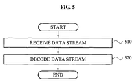
- FIG. 5 is a flowchart illustrating a method of receiving broadcasting data according to an embodiment of the present invention.
- a broadcasting data reception apparatus may receive data streams via a plurality of receive antennas.
- the data streams may be transmitted via a plurality of transmit antennas installed in a broadcasting data transmission apparatus.
- a modulation scheme may be differently determined for each transmit antenna.
- a precoding matrix may be determined based on the modulation scheme that is differently determined for each transmit antenna.
- An input vector including each data stream may be precoded using the precoding matrix.
- a precoding vector may include a plurality of column vectors orthogonal to each other.
- a rotation angle of the precoding vector may be determined based on the modulation scheme that is determined for each transmit antenna.
- Each column vector may be determined based on the rotation angle of the precoding vector.
- the precoding vector may be determined according to Equation 2.
- the broadcasting data reception apparatus may decode the received data streams.
- the broadcasting data reception apparatus may decode the data streams using an ML decoding scheme according to Equation 5.
- the above-described exemplary embodiments of the present invention may be recorded in computer-readable media including program instructions to implement various operations embodied by a computer.
- the media may also include, alone or in combination with the program instructions, data files, data structures, and the like.
- Examples of computer-readable media include magnetic media such as hard disks, floppy disks, and magnetic tape; optical media such as CD ROM disks and DVDs; magneto-optical media such as floptical disks; and hardware devices that are specially configured to store and perform program instructions, such as read-only memory (ROM), random access memory (RAM), flash memory, and the like.
- Examples of program instructions include both machine code, such as produced by a compiler, and files containing higher level code that may be executed by the computer using an interpreter.
- the described hardware devices may be configured to act as one or more software modules in order to perform the operations of the above-described exemplary embodiments of the present invention, or vice versa.
Landscapes
- Engineering & Computer Science (AREA)
- Computer Networks & Wireless Communication (AREA)
- Signal Processing (AREA)
- Power Engineering (AREA)
- Quality & Reliability (AREA)
- Artificial Intelligence (AREA)
- Radio Transmission System (AREA)
- Mobile Radio Communication Systems (AREA)
Abstract
Description
- Embodiments of the present invention relate to a system for transmitting broadcasting data, and more particularly, to a system for enhancing the receive performance by series connecting a spatial multiplexing system and a precoder in a mobile broadcasting channel environment.
- In a wireless communication environment, a multiple input multiple output (MIMO) communication system may obtain a high data rate using a plurality of transmit and receive antennas and thus, is currently gaining great attention. In particular, a spatial multiplexing scheme referred as Vertical Bell-labs Layered Space-Time (V-BLAST) may simultaneously transmit independent signal streams via respective transmit antennas, thereby enhancing the spectrum efficiency.
- However, when the spatial multiplexing scheme is applied to a mobile broadcasting system, a few problems may occur. Initially, significant performance degradation may occur in an erasure fading channel environment that occurs in a single frequency network (SFN) environment within a broadcasting system. The erasure fading channel environment may correspond to a fading channel in which information of a signal is erased when the signal passes a channel where fading occurs.
- In addition, in the case of a channel environment where correlation between transmit antennas and receive antennas occurs within the broadcasting system, an existing scheme may have the performance degradation. This is because the existing spatial multiplexing scheme using multiple transmit and receive antennas is designed based on the assumption that channel values between the transmit antennas and the receive antennas within a mobile communication system are independent. However, unlike the mobile communication system, in the broadcasting system, an occurrence probability of the correlation between the transmit antennas and the receive antennas may be high.
- Accordingly, in such channel environment, the existing spatial multiplexing scheme may have a great performance degradation.
- An aspect of the present invention provides a method that may enhance a data transmission performance in a fading channel.
- Another aspect of the present invention also provides a method that may prevent the degradation in the transmission performance of broadcasting data occurring by fading.
- According to an aspect of the present invention, there is provided a method of transmitting broadcasting data, the method including: controlling a transmission power of a data stream, transmitted via each of a plurality of transmit antennas, to be different based on a modulation scheme that is determined to be different for each of the transmit antennas; precoding the data stream of which the transmission power is controlled, using a precoding matrix that is determined based on the modulation scheme; and transmitting the precoded data stream to a receiver via each of the transmit antennas.
- According to another aspect of the present invention, there is provided a method of transmitting broadcasting data, the method including: controlling a transmission power of a data stream, transmitted via each of a plurality of transmit antennas, to be different based on a modulation scheme that is determined to be different for each of the transmit antennas; precoding the data stream of which the transmission power is controlled, using a precoding matrix that is determined based on the modulation scheme; shifting a phase of a data stream transmitted via a predetermined transmit antenna among the plurality of transmit antennas; and transmitting the phase-shifted data stream to a receiver via the predetermined transmit antenna.
- According to still another aspect of the present invention, there is provided a method of receiving broadcasting data, including: receiving, via a plurality of receive antennas, data streams that are precoded using a precoding matrix that is determined based on a modulation scheme, the modulation scheme being determined to be different for each of a plurality of transmit antennas; and decoding the data streams.
- According to embodiments of the present invention, it is possible to enhance a data transmission performance in a fading channel.
- According to embodiments of the present invention, it is possible to prevent the degradation in the transmission performance of broadcasting data occurring by fading.
-
-
FIG. 1 is a diagram illustrating a system for transmitting broadcasting data according to an embodiment of the present invention; -
FIG. 2 is a diagram illustrating a system for transmitting broadcasting data according to another embodiment of the present invention; -
FIG. 3 is a flowchart illustrating a method of transmitting broadcasting data according to an embodiment of the present invention; -
FIG. 4 is a flowchart illustrating a method of transmitting broadcasting data according to another embodiment of the present invention; and -
FIG. 5 is a flowchart illustrating a method of receiving broadcasting data according to an embodiment of the present invention. - Reference will now be made in detail to embodiments of the present invention, examples of which are illustrated in the accompanying drawings, wherein like reference numerals refer to the like elements throughout. The embodiments are described below in order to explain the present invention by referring to the figures.
-
FIG. 1 is a diagram illustrating a system for transmitting broadcasting data according to an embodiment of the present invention. - The proposed system may receive an input vector 110 x=[x 1,x2] T including two quadrature amplitude modulation (QAM) signals. Each element of the input vector x may correspond to a portion of a data stream to be transmitted by a broadcasting data transmission apparatus.
- A
precoder 120 may precode theinput vector 110 using a precoding matrix Θ. Theprecoder 120 may generate a precoded data stream by multiplying the input vector x by the precoding matrix Θ . A signal vector r including the precoded data stream as an element may be defined as Equation 1:
- According to an aspect, the precoding matrix Θ may include a plurality of column vectors. In this instance, the plurality of column vectors may be orthogonal to each other. Each of the column vectors of the precoding matrix Θ may correspond to a column vector that is defined based on a predetermined rotation angle.
- The precoding matrix Θ including the plurality of column vectors defined based on the predetermined rotation angle may be expressed by Equation 2:

- In
Equation 2, each of the column vectors may be defined based on the predetermined rotation angle and the plurality of column vectors may be orthogonal to each other. - Elements of the signal vector r may be transmitted to a broadcasting data reception apparatus via
corresponding transmit antennas - The signal vector r may be distorted while passing through
radio channels radio channels - The
radio channels 
- In Equation 3, hi,j corresponds to a complex fading value between an ith transmit antenna and a jth receive antenna and may have an independent and identically distributed (i.i.d.) Gaussian distribution in which each of a real number portion and an imaginary number portion has the average of "0" and a variance of "0.5". Also, ei,j corresponds to an erasure value between the ith transmit antenna and the jth receive antenna, and may have a value of "0" as a value of pe probability and has a value of "1" as a value of (1- pe ) probability.
- Considering the above description, a received vector y = [y1,y2] T received via a receive antenna, for example, receive
antennas 
- In Equation 4, n = [n1,n2] T denotes a thermal noise vector occurring in each receive antenna. Here, ni corresponds to an i.i.d. additive white Gaussian noise (AWGN) sample value with respect to an ith receive antenna. Each of a real number portion and an imaginary number portion may have a bi-directional power density of N0/2.
- A maximum likelihood (ML)
decoder 170 may decode data streams using an ML decoding scheme. For example, theML decoder 170 may perform ML decoding using a value h of an estimated channel matrix, according to Equation 5:
- In Equation 5, x̂ denotes an
output vector 180 minimizing the received vector y and a Euclidean distance. - According to an aspect, the precoding matrix Θ may be optimized to maximize the receive performance of the
ML decoder 170. When considering the independency and symmetry of two receiveantennas FIG. 1 , the precoding matrix Θ maximizing the performance of a predetermined receive antenna may also maximize the performance of the whole receiveantennas - Accordingly, hereinafter, description will be made based on the precoding matrix Θ optimized based on only a first receive antenna.
- A signal received by the first receive antenna may be expressed by Equation 6:

- Here, (e 1,1,e 2,1) by erasure fading may have four values of (0, 0), (1, 1), (1, 0), and (0, 1). Hereinafter, a value of the precoding matrix Θ with respect to each case will be described.
- 1) When (e 1,1,e 2,1) corresponds to (0, 0):
- In this case, all of two transmission signals may be erased and only noise may be present in a received signal. Accordingly, there is no meaning in optimizing a value of the precoding matrix Θ with respect to the above case.
- 2) When (e 1,1,e 2,1) corresponds to (1, 1):
- In this case, a channel may be considered as a non-erasure channel. Accordingly, Equation 6 may be arranged to Equation 7:

In Equation 7, α1 and α2 correspond to effective channels based on actual channels h 1,1, h 2,1 and a value of the precoding matrix Θ .Due to the unitary characteristic of the precoding matrix Θ, values of α 1 and α 2 may have an i.i.d. Gaussian distribution. Accordingly, it can be known that the receive performance does not vary according to a change in the value of the precoding matrix Θ
- In this case, a channel may be considered as a non-erasure channel. Accordingly, Equation 6 may be arranged to Equation 7:
- 3) When (e 1,1 ,e 2,1) corresponds to (1, 0):
- In this case, Equation 6 may be rearranged to Equation 8:

Referring to Equation 8, a single channel environment where only a channel from the first transmit antenna is present may be considered. An optimal constellation of transmitting four bits in a rectangular structure in the single channel environment may be 16-QAM. Accordingly, in Equation 8, s(x 1,x 2) may need to have a constellation of 16-QAM. Based on this, it can be known that the optimal value of θ may need to have a value of θ tan-1(1/2)±nπ7/2. - In this case, Equation 6 may be rearranged to Equation 8:
- 4) When (e 1,1,e 2,1) corresponds to (0, 1):
- Even in this case, it can be known that the optimal value of θ is θ = tan-1(1/2)±nπ/2 through analysis similar to the case 3).
- In the case 3) and the case 4), the optimal value of θ may correspond to a value with respect to a 4-QAM modulation scheme and the optimal value of θ with respect to another modulation order may also be simply induced. For example, when a 16-QAM modulation scheme is employed, the optimal value of θ may enable (cosθx 1 + sin θx 2) or (-sinθx 1+cosθx 2)signals to have a 256-QAM constellation. Accordingly, it can be known that the optimal value of θ corresponds to θ = tan-1(1/4)± nπ/2.
- Also, when considering a predetermined modulation order M-QAM, the optimal value of θ may correspond to

- According to an aspect, correlation between transmit antennas and receive antennas may occur. In particular, since a position of a transmission station is relatively higher than a terminal station in a mobile broadcasting system, a probability that the correlation between the transmit antennas and the receive antennas may occur may increase. By controlling a power of each data stream included in an input vector to be different, it is possible to enhance the receive performance even in a channel environment where the correlation exists.
- When the power of each data stream included in the input vector x is controlled to be different, the input vector x may be defined as Equation 9:

- In Equation 9, α denotes a variable for controlling the transmission power of each data stream, included in the input vector x, to be different and may have a value of between "0" and "1". Since E{∥ x ∥2} = 1, the whole power of the input vector x expressed in Equation 9 may be constant.
- The
precoder 120 may precode the input vector x of Equation 9 using the precoding matrix Θ. For example, theprecoder 120 may generate a precoded data stream by multiplying the input vector x by the precoding matrix Θ. -
FIG. 2 is a diagram illustrating a system for transmitting broadcasting data according to another embodiment of the present invention. Aprecoder 220 and anML decoder 280 included in the broadcasting data transmission system ofFIG. 2 may function as similar to theprecoder 120 and theML decoder 170 ofFIG. 1 . - The broadcasting data transmission system of
FIG. 2 may include a phase shifter 223 to shift a phase of a data stream precoded by theprecoder 220. The phase shifter 223 may be installed in only anantenna 242, instead of areference antenna 241. Also, the phase shifter 223 may shift, to a random phase, a phase of a data stream transmitted via theantenna 242. - When the phase of the data stream is shifted to the random phase by the phase shifter 223, correlation between data streams using antennas may decrease. Accordingly, the performance of multiple input multiple output (MIMO) spatial multiplexing may be optimized.
- When a modulation scheme of each antenna is different, a rotation angle of a precoding matrix may be optimized, which is described above with reference to
FIG. 1 . The transmission power of each data stream included in an input vector x may be optimized. - When the input vector x is expressed like Equation α optimizing the transmission power of each data stream and the rotation angle θ of the precoding matrix according to α may have values expressed by Equation 10:

-
FIG. 3 is a flowchart illustrating a method of transmitting broadcasting data according to an embodiment of the present invention. - In
operation 310, a broadcasting data transmission system may control a transmission power of a data stream, included in an input vector x, to be different. The input vector x may be expressed according to Equation 9. In this case, the broadcasting data transmission system may control the transmission power by controlling a value of α. - According to an aspect, a data stream may be transmitted to a broadcasting data reception apparatus via a plurality of transmit antennas. In this case, a modulation scheme of each of the antennas may be different. A broadcasting data transmission apparatus may determine a transmission power of the data stream based on the modulation scheme that is determined to be different for each antenna. That is, a size of each element included in the input vector x may be differently determined.
- In
operation 320, a broadcasting data transmission apparatus may precode the data stream of which the transmission power is controlled, using a precoding matrix that is determined based on the modulation scheme differently determined for each antenna. The broadcasting data transmission apparatus may perform precoding by multiplying the input vector x by the precoding matrix. - According to an aspect, the precoding matrix may include a plurality of column vectors. Each of the column vectors may be determined based on the modulation scheme of each antenna. For example, the rotation angle of the precoding matrix may be determined based on the modulation scheme of each antenna and each column vector may be determined based on the rotation angle of the precoding matrix. The precoding matrix may be determined as expressed by
Equation 2. - When the modulation scheme of each antenna corresponds to an M-QAM, the optimal value of the rotation angle θ may be determined as

- In
operation 330, the broadcasting data transmission apparatus may transmit the precoded data stream to the broadcasting data reception apparatus. -
FIG. 4 is a flowchart illustrating a method of transmitting broadcasting data according to another embodiment of the present invention. -
Operations FIG. 4 may be similar tooperations FIG. 3 and thus, further description related thereto will be omitted here. - In
operation 430, a broadcasting data transmission apparatus may randomly shift a phase of a data stream transmitted via each antenna. When the phase of the data stream is shifted, correlation between data streams transmitted via respective antennas may decrease and the performance of MIMO spatial multiplexing may be optimized. - When the input vector x is expressed like Equation α optimizing the transmission power of each data stream and the rotation angle θ of the precoding matrix according to α may have values expressed by Equation 10. When α is identical to Equation 10, a transmission power of a data stream transmitted via a first transmit antenna may correspond to two folds of a transmission power of a data stream transmitted via a second transmit antenna.
- In
operation 440, the broadcasting data transmission apparatus may transmit the precoded data stream to the broadcasting data reception apparatus via a plurality of transmit antennas. -
FIG. 5 is a flowchart illustrating a method of receiving broadcasting data according to an embodiment of the present invention. - In
operation 510, a broadcasting data reception apparatus may receive data streams via a plurality of receive antennas. The data streams may be transmitted via a plurality of transmit antennas installed in a broadcasting data transmission apparatus. According to an aspect, a modulation scheme may be differently determined for each transmit antenna. In this case, a precoding matrix may be determined based on the modulation scheme that is differently determined for each transmit antenna. An input vector including each data stream may be precoded using the precoding matrix. - According to an aspect, a precoding vector may include a plurality of column vectors orthogonal to each other. According to an aspect, a rotation angle of the precoding vector may be determined based on the modulation scheme that is determined for each transmit antenna. Each column vector may be determined based on the rotation angle of the precoding vector. The precoding vector may be determined according to
Equation 2. - In
operation 520, the broadcasting data reception apparatus may decode the received data streams. The broadcasting data reception apparatus may decode the data streams using an ML decoding scheme according to Equation 5. - The above-described exemplary embodiments of the present invention may be recorded in computer-readable media including program instructions to implement various operations embodied by a computer. The media may also include, alone or in combination with the program instructions, data files, data structures, and the like. Examples of computer-readable media include magnetic media such as hard disks, floppy disks, and magnetic tape; optical media such as CD ROM disks and DVDs; magneto-optical media such as floptical disks; and hardware devices that are specially configured to store and perform program instructions, such as read-only memory (ROM), random access memory (RAM), flash memory, and the like. Examples of program instructions include both machine code, such as produced by a compiler, and files containing higher level code that may be executed by the computer using an interpreter. The described hardware devices may be configured to act as one or more software modules in order to perform the operations of the above-described exemplary embodiments of the present invention, or vice versa.
- Although a few embodiments of the present invention have been shown and described, the present invention is not limited to the described embodiments. Instead, it would be appreciated by those skilled in the art that changes may be made to these embodiments without departing from the principles and spirit of the invention, the scope of which is defined by the claims and their equivalents.
Claims (15)
- A method of transmitting broadcasting data, the method comprising:controlling a transmission power of a data stream, transmitted via each of a plurality of transmit antennas, to be different based on a modulation scheme that is determined to be different for each of the transmit antennas;precoding the data stream of which the transmission power is controlled, using a precoding matrix that is determined based on the modulation scheme; andtransmitting the precoded data stream to a receiver via each of the transmit antennas.
- The method of claim 1, wherein the precoding matrix comprises a plurality of column vectors orthogonal to each other.
- The method of claim 2, wherein each of the column vectors corresponds to a unit vector that is determined based on the modulation scheme.
- The method of claim 3, wherein the precoding matrix is determined according to Equation 1:

where Θ denotes the precoding matrix and θ denotes a rotation angle of the precoding matrix that is determined based on the modulation scheme. - The method of claim 4, wherein when the modulation scheme corresponds to an M-quadrature amplitude modulation (QAM), the rotation angle θ of the precoding matrix is determined according to Equation 2:

where n denotes a predetermined integer. - A method of transmitting broadcasting data, the method comprising:controlling a transmission power of a data stream, transmitted via each of a plurality of transmit antennas, to be different based on a modulation scheme that is determined to be different for each of the transmit antennas;precoding the data stream of which the transmission power is controlled, using a precoding matrix that is determined based on the modulation scheme;shifting a phase of a data stream transmitted via a predetermined transmit antenna among the plurality of transmit antennas; andtransmitting the phase-shifted data stream to a receiver via the predetermined transmit antenna.
- The method of claim 6, wherein the precoding matrix comprises a plurality of column vectors orthogonal to each other.
- The method of claim 7, wherein each of the column vectors corresponds to a unit vector that is determined based on the modulation scheme.
- The method of claim 6, wherein the precoding matrix is determined according to Equation 3:

where Θ denotes the precoding matrix and θ denotes a rotation angle of the precoding matrix that is determined based on the modulation scheme. - The method of claim 6, wherein a number of transmit antennas is two, a transmission power of a data stream transmitted via a first transmit antenna corresponds to two folds of a transmission power of a data stream transmitted via a second transmit antenna.
- The method of claim 9, wherein a number of transmit antennas is two, and the rotation angle θ is determined as 30 degrees or 45 degrees.
- A method of receiving broadcasting data, comprising:receiving, via a plurality of receive antennas, data streams that are precoded using a precoding matrix that is determined based on a modulation scheme, the modulation scheme being determined to be different for each of a plurality of transmit antennas; anddecoding the data streams.
- The method of claim 12, wherein the decoding comprises decoding the data streams using a maximum likelihood (ML) decoding scheme.
- The method of claim 12, wherein the precoding matrix comprises a plurality of column vectors orthogonal to each other.
- The method of claim 12, wherein the precoding matrix is determined according to Equation 5:

where Θ denotes the precoding matrix and θ denotes a rotation angle of the precoding matrix that is determined based on the modulation scheme.
Applications Claiming Priority (5)
| Application Number | Priority Date | Filing Date | Title |
|---|---|---|---|
| KR20100057899 | 2010-06-18 | ||
| KR20100081521 | 2010-08-23 | ||
| KR20110015183 | 2011-02-21 | ||
| KR1020110035727A KR101799108B1 (en) | 2010-06-18 | 2011-04-18 | System for transmitting broadcasting data |
| PCT/KR2011/004396 WO2011159103A2 (en) | 2010-06-18 | 2011-06-16 | Broadcast data transmission system |
Publications (3)
| Publication Number | Publication Date |
|---|---|
| EP2584712A2 true EP2584712A2 (en) | 2013-04-24 |
| EP2584712A4 EP2584712A4 (en) | 2017-06-07 |
| EP2584712B1 EP2584712B1 (en) | 2019-12-18 |
Family
ID=45504185
Family Applications (1)
| Application Number | Title | Priority Date | Filing Date |
|---|---|---|---|
| EP11795969.2A Active EP2584712B1 (en) | 2010-06-18 | 2011-06-16 | Broadcast data transmission method |
Country Status (4)
| Country | Link |
|---|---|
| EP (1) | EP2584712B1 (en) |
| KR (1) | KR101799108B1 (en) |
| CN (1) | CN103339872B (en) |
| WO (1) | WO2011159103A2 (en) |
Family Cites Families (7)
| Publication number | Priority date | Publication date | Assignee | Title |
|---|---|---|---|---|
| US7729232B2 (en) * | 2006-02-01 | 2010-06-01 | Lg Electronics Inc. | Method of transmitting and receiving data using superposition modulation in a wireless communication system |
| CN101558620B (en) * | 2006-05-19 | 2014-11-12 | Lg电子株式会社 | A method of utilizing and manipulating wireless resources for efficient and effective wireless communication |
| US8929485B2 (en) * | 2006-06-16 | 2015-01-06 | Samsung Electronics Co., Ltd. | System and method for broadcast pre-coding in a MIMO system |
| CN101242205A (en) * | 2007-02-09 | 2008-08-13 | 联想(北京)有限公司 | A space sub-channel rate and power control method and its control device |
| KR20080080722A (en) * | 2007-03-02 | 2008-09-05 | 삼성전자주식회사 | Apparatus and method for non linear pre-coding in multi antenna system |
| KR101499255B1 (en) * | 2008-03-12 | 2015-03-06 | 엘지전자 주식회사 | Method of transmitting pilot in multiple antenna system |
| CN101540690B (en) * | 2008-03-21 | 2011-09-14 | 华为技术有限公司 | Method and system for MIMO communication of multicast service |
-
2011
- 2011-04-18 KR KR1020110035727A patent/KR101799108B1/en active IP Right Grant
- 2011-06-16 CN CN201180039917.7A patent/CN103339872B/en not_active Expired - Fee Related
- 2011-06-16 EP EP11795969.2A patent/EP2584712B1/en active Active
- 2011-06-16 WO PCT/KR2011/004396 patent/WO2011159103A2/en active Application Filing
Non-Patent Citations (1)
| Title |
|---|
| See references of WO2011159103A2 * |
Also Published As
| Publication number | Publication date |
|---|---|
| CN103339872A (en) | 2013-10-02 |
| WO2011159103A3 (en) | 2012-02-23 |
| WO2011159103A2 (en) | 2011-12-22 |
| KR20110138146A (en) | 2011-12-26 |
| EP2584712B1 (en) | 2019-12-18 |
| EP2584712A4 (en) | 2017-06-07 |
| KR101799108B1 (en) | 2017-11-17 |
| CN103339872B (en) | 2016-03-16 |
Similar Documents
| Publication | Publication Date | Title |
|---|---|---|
| Sharma et al. | Improved quasi-orthogonal codes through constellation rotation | |
| US11140017B2 (en) | Data transmission method and apparatus | |
| US7995670B2 (en) | Method of transmitting and receiving data using precoding codebook in multi-user MIMO communication system and transmitter and receiver using the method | |
| US7564915B2 (en) | Apparatus and method for coding/decoding pseudo orthogonal space-time block code in a mobile communication system using multiple input multiple output scheme | |
| US9813278B1 (en) | Quadrature spatial modulation system | |
| EP1655875A2 (en) | Apparatus and method for space-time-frequency block coding | |
| US9432097B2 (en) | Enhanced modulation | |
| US20200036416A1 (en) | Transmission method and transmission device | |
| CN102571290B (en) | Pre-coding transmitting method based on link self-adaption for multiple input multiple output (MIMO) system | |
| EP1641166A2 (en) | Apparatus and method for full-diversity, full-rate space-time block coding for two transmit antennas | |
| CN101267234B (en) | Space time packet coding and decoding method and device | |
| EP2584712B1 (en) | Broadcast data transmission method | |
| Choi et al. | Alamouti-codes based four-antenna transmission schemes with phase feedback | |
| US8711965B2 (en) | Method and apparatus for optimizing transmission diversity | |
| Debels et al. | SNR maximization and modulo loss reduction for Tomlinson-Harashima precoding | |
| Le et al. | Efficient algorithm for blind detection of orthogonal space-time block codes | |
| Ji et al. | A new differential space-time modulation scheme based on weyl group | |
| Jia et al. | PSK modulated differential spatial modulation for massive MIMO uplink system | |
| Koca et al. | Precoded Spatial Modulation for Robustness against Correlated Rician Fading | |
| Zhang et al. | A low complexity HD detector for dual polarized spatial modulation | |
| Shitomi et al. | Performance evaluation of MIMO channel estimation for ATSC 3.0 | |
| Cano et al. | Space-time differential modulation using linear constellation precoding | |
| Yue et al. | High rate transmit diversity assisted space shift keying modulation over MIMO channels | |
| Ramadhan | Space-Time Coding STC | |
| Li et al. | Capacity of maximal ratio combining reception over correlated Nakagami fading channels |
Legal Events
| Date | Code | Title | Description |
|---|---|---|---|
| PUAI | Public reference made under article 153(3) epc to a published international application that has entered the european phase |
Free format text: ORIGINAL CODE: 0009012 |
|
| 17P | Request for examination filed |
Effective date: 20130118 |
|
| AK | Designated contracting states |
Kind code of ref document: A2 Designated state(s): AL AT BE BG CH CY CZ DE DK EE ES FI FR GB GR HR HU IE IS IT LI LT LU LV MC MK MT NL NO PL PT RO RS SE SI SK SM TR |
|
| DAX | Request for extension of the european patent (deleted) | ||
| RAP1 | Party data changed (applicant data changed or rights of an application transferred) |
Owner name: ELECTRONICS AND TELECOMMUNICATIONS RESEARCH INSTIT |
|
| A4 | Supplementary search report drawn up and despatched |
Effective date: 20170510 |
|
| RIC1 | Information provided on ipc code assigned before grant |
Ipc: H04B 7/04 20170101AFI20170503BHEP Ipc: H04L 27/00 20060101ALN20170503BHEP Ipc: H04B 7/06 20060101ALN20170503BHEP Ipc: H04L 1/00 20060101ALI20170503BHEP |
|
| STAA | Information on the status of an ep patent application or granted ep patent |
Free format text: STATUS: EXAMINATION IS IN PROGRESS |
|
| 17Q | First examination report despatched |
Effective date: 20190204 |
|
| REG | Reference to a national code |
Ref country code: DE Ref legal event code: R079 Ref document number: 602011064112 Country of ref document: DE Free format text: PREVIOUS MAIN CLASS: H04B0007040000 Ipc: H04B0007042600 |
|
| GRAP | Despatch of communication of intention to grant a patent |
Free format text: ORIGINAL CODE: EPIDOSNIGR1 |
|
| STAA | Information on the status of an ep patent application or granted ep patent |
Free format text: STATUS: GRANT OF PATENT IS INTENDED |
|
| RIC1 | Information provided on ipc code assigned before grant |
Ipc: H04L 27/36 20060101ALI20190619BHEP Ipc: H04B 7/06 20060101ALN20190619BHEP Ipc: H04B 7/0426 20170101AFI20190619BHEP Ipc: H04W 52/26 20090101ALI20190619BHEP Ipc: H04L 27/00 20060101ALN20190619BHEP |
|
| INTG | Intention to grant announced |
Effective date: 20190719 |
|
| GRAS | Grant fee paid |
Free format text: ORIGINAL CODE: EPIDOSNIGR3 |
|
| GRAA | (expected) grant |
Free format text: ORIGINAL CODE: 0009210 |
|
| STAA | Information on the status of an ep patent application or granted ep patent |
Free format text: STATUS: THE PATENT HAS BEEN GRANTED |
|
| AK | Designated contracting states |
Kind code of ref document: B1 Designated state(s): AL AT BE BG CH CY CZ DE DK EE ES FI FR GB GR HR HU IE IS IT LI LT LU LV MC MK MT NL NO PL PT RO RS SE SI SK SM TR |
|
| REG | Reference to a national code |
Ref country code: GB Ref legal event code: FG4D |
|
| REG | Reference to a national code |
Ref country code: CH Ref legal event code: EP |
|
| REG | Reference to a national code |
Ref country code: IE Ref legal event code: FG4D |
|
| REG | Reference to a national code |
Ref country code: DE Ref legal event code: R096 Ref document number: 602011064112 Country of ref document: DE |
|
| REG | Reference to a national code |
Ref country code: AT Ref legal event code: REF Ref document number: 1215706 Country of ref document: AT Kind code of ref document: T Effective date: 20200115 |
|
| REG | Reference to a national code |
Ref country code: NL Ref legal event code: MP Effective date: 20191218 |
|
| PG25 | Lapsed in a contracting state [announced via postgrant information from national office to epo] |
Ref country code: GR Free format text: LAPSE BECAUSE OF FAILURE TO SUBMIT A TRANSLATION OF THE DESCRIPTION OR TO PAY THE FEE WITHIN THE PRESCRIBED TIME-LIMIT Effective date: 20200319 Ref country code: BG Free format text: LAPSE BECAUSE OF FAILURE TO SUBMIT A TRANSLATION OF THE DESCRIPTION OR TO PAY THE FEE WITHIN THE PRESCRIBED TIME-LIMIT Effective date: 20200318 Ref country code: LT Free format text: LAPSE BECAUSE OF FAILURE TO SUBMIT A TRANSLATION OF THE DESCRIPTION OR TO PAY THE FEE WITHIN THE PRESCRIBED TIME-LIMIT Effective date: 20191218 Ref country code: FI Free format text: LAPSE BECAUSE OF FAILURE TO SUBMIT A TRANSLATION OF THE DESCRIPTION OR TO PAY THE FEE WITHIN THE PRESCRIBED TIME-LIMIT Effective date: 20191218 Ref country code: SE Free format text: LAPSE BECAUSE OF FAILURE TO SUBMIT A TRANSLATION OF THE DESCRIPTION OR TO PAY THE FEE WITHIN THE PRESCRIBED TIME-LIMIT Effective date: 20191218 Ref country code: NO Free format text: LAPSE BECAUSE OF FAILURE TO SUBMIT A TRANSLATION OF THE DESCRIPTION OR TO PAY THE FEE WITHIN THE PRESCRIBED TIME-LIMIT Effective date: 20200318 Ref country code: LV Free format text: LAPSE BECAUSE OF FAILURE TO SUBMIT A TRANSLATION OF THE DESCRIPTION OR TO PAY THE FEE WITHIN THE PRESCRIBED TIME-LIMIT Effective date: 20191218 |
|
| REG | Reference to a national code |
Ref country code: LT Ref legal event code: MG4D |
|
| PG25 | Lapsed in a contracting state [announced via postgrant information from national office to epo] |
Ref country code: RS Free format text: LAPSE BECAUSE OF FAILURE TO SUBMIT A TRANSLATION OF THE DESCRIPTION OR TO PAY THE FEE WITHIN THE PRESCRIBED TIME-LIMIT Effective date: 20191218 Ref country code: HR Free format text: LAPSE BECAUSE OF FAILURE TO SUBMIT A TRANSLATION OF THE DESCRIPTION OR TO PAY THE FEE WITHIN THE PRESCRIBED TIME-LIMIT Effective date: 20191218 |
|
| PG25 | Lapsed in a contracting state [announced via postgrant information from national office to epo] |
Ref country code: AL Free format text: LAPSE BECAUSE OF FAILURE TO SUBMIT A TRANSLATION OF THE DESCRIPTION OR TO PAY THE FEE WITHIN THE PRESCRIBED TIME-LIMIT Effective date: 20191218 |
|
| PG25 | Lapsed in a contracting state [announced via postgrant information from national office to epo] |
Ref country code: EE Free format text: LAPSE BECAUSE OF FAILURE TO SUBMIT A TRANSLATION OF THE DESCRIPTION OR TO PAY THE FEE WITHIN THE PRESCRIBED TIME-LIMIT Effective date: 20191218 Ref country code: NL Free format text: LAPSE BECAUSE OF FAILURE TO SUBMIT A TRANSLATION OF THE DESCRIPTION OR TO PAY THE FEE WITHIN THE PRESCRIBED TIME-LIMIT Effective date: 20191218 Ref country code: CZ Free format text: LAPSE BECAUSE OF FAILURE TO SUBMIT A TRANSLATION OF THE DESCRIPTION OR TO PAY THE FEE WITHIN THE PRESCRIBED TIME-LIMIT Effective date: 20191218 Ref country code: RO Free format text: LAPSE BECAUSE OF FAILURE TO SUBMIT A TRANSLATION OF THE DESCRIPTION OR TO PAY THE FEE WITHIN THE PRESCRIBED TIME-LIMIT Effective date: 20191218 Ref country code: PT Free format text: LAPSE BECAUSE OF FAILURE TO SUBMIT A TRANSLATION OF THE DESCRIPTION OR TO PAY THE FEE WITHIN THE PRESCRIBED TIME-LIMIT Effective date: 20200513 |
|
| PGFP | Annual fee paid to national office [announced via postgrant information from national office to epo] |
Ref country code: DE Payment date: 20200520 Year of fee payment: 10 |
|
| PG25 | Lapsed in a contracting state [announced via postgrant information from national office to epo] |
Ref country code: SK Free format text: LAPSE BECAUSE OF FAILURE TO SUBMIT A TRANSLATION OF THE DESCRIPTION OR TO PAY THE FEE WITHIN THE PRESCRIBED TIME-LIMIT Effective date: 20191218 Ref country code: IS Free format text: LAPSE BECAUSE OF FAILURE TO SUBMIT A TRANSLATION OF THE DESCRIPTION OR TO PAY THE FEE WITHIN THE PRESCRIBED TIME-LIMIT Effective date: 20200418 Ref country code: SM Free format text: LAPSE BECAUSE OF FAILURE TO SUBMIT A TRANSLATION OF THE DESCRIPTION OR TO PAY THE FEE WITHIN THE PRESCRIBED TIME-LIMIT Effective date: 20191218 |
|
| REG | Reference to a national code |
Ref country code: DE Ref legal event code: R097 Ref document number: 602011064112 Country of ref document: DE |
|
| REG | Reference to a national code |
Ref country code: AT Ref legal event code: MK05 Ref document number: 1215706 Country of ref document: AT Kind code of ref document: T Effective date: 20191218 |
|
| PLBE | No opposition filed within time limit |
Free format text: ORIGINAL CODE: 0009261 |
|
| STAA | Information on the status of an ep patent application or granted ep patent |
Free format text: STATUS: NO OPPOSITION FILED WITHIN TIME LIMIT |
|
| PG25 | Lapsed in a contracting state [announced via postgrant information from national office to epo] |
Ref country code: ES Free format text: LAPSE BECAUSE OF FAILURE TO SUBMIT A TRANSLATION OF THE DESCRIPTION OR TO PAY THE FEE WITHIN THE PRESCRIBED TIME-LIMIT Effective date: 20191218 Ref country code: DK Free format text: LAPSE BECAUSE OF FAILURE TO SUBMIT A TRANSLATION OF THE DESCRIPTION OR TO PAY THE FEE WITHIN THE PRESCRIBED TIME-LIMIT Effective date: 20191218 |
|
| 26N | No opposition filed |
Effective date: 20200921 |
|
| PG25 | Lapsed in a contracting state [announced via postgrant information from national office to epo] |
Ref country code: SI Free format text: LAPSE BECAUSE OF FAILURE TO SUBMIT A TRANSLATION OF THE DESCRIPTION OR TO PAY THE FEE WITHIN THE PRESCRIBED TIME-LIMIT Effective date: 20191218 Ref country code: AT Free format text: LAPSE BECAUSE OF FAILURE TO SUBMIT A TRANSLATION OF THE DESCRIPTION OR TO PAY THE FEE WITHIN THE PRESCRIBED TIME-LIMIT Effective date: 20191218 |
|
| PG25 | Lapsed in a contracting state [announced via postgrant information from national office to epo] |
Ref country code: IT Free format text: LAPSE BECAUSE OF FAILURE TO SUBMIT A TRANSLATION OF THE DESCRIPTION OR TO PAY THE FEE WITHIN THE PRESCRIBED TIME-LIMIT Effective date: 20191218 Ref country code: MC Free format text: LAPSE BECAUSE OF FAILURE TO SUBMIT A TRANSLATION OF THE DESCRIPTION OR TO PAY THE FEE WITHIN THE PRESCRIBED TIME-LIMIT Effective date: 20191218 |
|
| REG | Reference to a national code |
Ref country code: CH Ref legal event code: PL |
|
| PG25 | Lapsed in a contracting state [announced via postgrant information from national office to epo] |
Ref country code: PL Free format text: LAPSE BECAUSE OF FAILURE TO SUBMIT A TRANSLATION OF THE DESCRIPTION OR TO PAY THE FEE WITHIN THE PRESCRIBED TIME-LIMIT Effective date: 20191218 |
|
| GBPC | Gb: european patent ceased through non-payment of renewal fee |
Effective date: 20200616 |
|
| PG25 | Lapsed in a contracting state [announced via postgrant information from national office to epo] |
Ref country code: LU Free format text: LAPSE BECAUSE OF NON-PAYMENT OF DUE FEES Effective date: 20200616 |
|
| REG | Reference to a national code |
Ref country code: BE Ref legal event code: MM Effective date: 20200630 |
|
| PG25 | Lapsed in a contracting state [announced via postgrant information from national office to epo] |
Ref country code: FR Free format text: LAPSE BECAUSE OF NON-PAYMENT OF DUE FEES Effective date: 20200630 Ref country code: GB Free format text: LAPSE BECAUSE OF NON-PAYMENT OF DUE FEES Effective date: 20200616 Ref country code: IE Free format text: LAPSE BECAUSE OF NON-PAYMENT OF DUE FEES Effective date: 20200616 Ref country code: LI Free format text: LAPSE BECAUSE OF NON-PAYMENT OF DUE FEES Effective date: 20200630 Ref country code: CH Free format text: LAPSE BECAUSE OF NON-PAYMENT OF DUE FEES Effective date: 20200630 |
|
| PG25 | Lapsed in a contracting state [announced via postgrant information from national office to epo] |
Ref country code: BE Free format text: LAPSE BECAUSE OF NON-PAYMENT OF DUE FEES Effective date: 20200630 |
|
| REG | Reference to a national code |
Ref country code: DE Ref legal event code: R119 Ref document number: 602011064112 Country of ref document: DE |
|
| PG25 | Lapsed in a contracting state [announced via postgrant information from national office to epo] |
Ref country code: DE Free format text: LAPSE BECAUSE OF NON-PAYMENT OF DUE FEES Effective date: 20220101 |
|
| PG25 | Lapsed in a contracting state [announced via postgrant information from national office to epo] |
Ref country code: TR Free format text: LAPSE BECAUSE OF FAILURE TO SUBMIT A TRANSLATION OF THE DESCRIPTION OR TO PAY THE FEE WITHIN THE PRESCRIBED TIME-LIMIT Effective date: 20191218 Ref country code: MT Free format text: LAPSE BECAUSE OF FAILURE TO SUBMIT A TRANSLATION OF THE DESCRIPTION OR TO PAY THE FEE WITHIN THE PRESCRIBED TIME-LIMIT Effective date: 20191218 Ref country code: CY Free format text: LAPSE BECAUSE OF FAILURE TO SUBMIT A TRANSLATION OF THE DESCRIPTION OR TO PAY THE FEE WITHIN THE PRESCRIBED TIME-LIMIT Effective date: 20191218 |
|
| PG25 | Lapsed in a contracting state [announced via postgrant information from national office to epo] |
Ref country code: MK Free format text: LAPSE BECAUSE OF FAILURE TO SUBMIT A TRANSLATION OF THE DESCRIPTION OR TO PAY THE FEE WITHIN THE PRESCRIBED TIME-LIMIT Effective date: 20191218 |