EP2584644A1 - Battery cooling plate and cooling system - Google Patents
Battery cooling plate and cooling system Download PDFInfo
- Publication number
- EP2584644A1 EP2584644A1 EP20120188890 EP12188890A EP2584644A1 EP 2584644 A1 EP2584644 A1 EP 2584644A1 EP 20120188890 EP20120188890 EP 20120188890 EP 12188890 A EP12188890 A EP 12188890A EP 2584644 A1 EP2584644 A1 EP 2584644A1
- Authority
- EP
- European Patent Office
- Prior art keywords
- cooling
- shape
- cooling channel
- recited
- channel
- Prior art date
- Legal status (The legal status is an assumption and is not a legal conclusion. Google has not performed a legal analysis and makes no representation as to the accuracy of the status listed.)
- Granted
Links
Images


Classifications
-
- F—MECHANICAL ENGINEERING; LIGHTING; HEATING; WEAPONS; BLASTING
- F28—HEAT EXCHANGE IN GENERAL
- F28F—DETAILS OF HEAT-EXCHANGE AND HEAT-TRANSFER APPARATUS, OF GENERAL APPLICATION
- F28F3/00—Plate-like or laminated elements; Assemblies of plate-like or laminated elements
- F28F3/12—Elements constructed in the shape of a hollow panel, e.g. with channels
-
- H—ELECTRICITY
- H01—ELECTRIC ELEMENTS
- H01M—PROCESSES OR MEANS, e.g. BATTERIES, FOR THE DIRECT CONVERSION OF CHEMICAL ENERGY INTO ELECTRICAL ENERGY
- H01M10/00—Secondary cells; Manufacture thereof
- H01M10/60—Heating or cooling; Temperature control
- H01M10/61—Types of temperature control
- H01M10/613—Cooling or keeping cold
-
- H—ELECTRICITY
- H01—ELECTRIC ELEMENTS
- H01M—PROCESSES OR MEANS, e.g. BATTERIES, FOR THE DIRECT CONVERSION OF CHEMICAL ENERGY INTO ELECTRICAL ENERGY
- H01M10/00—Secondary cells; Manufacture thereof
- H01M10/60—Heating or cooling; Temperature control
- H01M10/61—Types of temperature control
- H01M10/617—Types of temperature control for achieving uniformity or desired distribution of temperature
-
- H—ELECTRICITY
- H01—ELECTRIC ELEMENTS
- H01M—PROCESSES OR MEANS, e.g. BATTERIES, FOR THE DIRECT CONVERSION OF CHEMICAL ENERGY INTO ELECTRICAL ENERGY
- H01M10/00—Secondary cells; Manufacture thereof
- H01M10/60—Heating or cooling; Temperature control
- H01M10/62—Heating or cooling; Temperature control specially adapted for specific applications
- H01M10/625—Vehicles
-
- H—ELECTRICITY
- H01—ELECTRIC ELEMENTS
- H01M—PROCESSES OR MEANS, e.g. BATTERIES, FOR THE DIRECT CONVERSION OF CHEMICAL ENERGY INTO ELECTRICAL ENERGY
- H01M10/00—Secondary cells; Manufacture thereof
- H01M10/60—Heating or cooling; Temperature control
- H01M10/65—Means for temperature control structurally associated with the cells
- H01M10/651—Means for temperature control structurally associated with the cells characterised by parameters specified by a numeric value or mathematical formula, e.g. ratios, sizes or concentrations
-
- H—ELECTRICITY
- H01—ELECTRIC ELEMENTS
- H01M—PROCESSES OR MEANS, e.g. BATTERIES, FOR THE DIRECT CONVERSION OF CHEMICAL ENERGY INTO ELECTRICAL ENERGY
- H01M10/00—Secondary cells; Manufacture thereof
- H01M10/60—Heating or cooling; Temperature control
- H01M10/65—Means for temperature control structurally associated with the cells
- H01M10/655—Solid structures for heat exchange or heat conduction
- H01M10/6556—Solid parts with flow channel passages or pipes for heat exchange
- H01M10/6557—Solid parts with flow channel passages or pipes for heat exchange arranged between the cells
-
- H—ELECTRICITY
- H01—ELECTRIC ELEMENTS
- H01M—PROCESSES OR MEANS, e.g. BATTERIES, FOR THE DIRECT CONVERSION OF CHEMICAL ENERGY INTO ELECTRICAL ENERGY
- H01M10/00—Secondary cells; Manufacture thereof
- H01M10/60—Heating or cooling; Temperature control
- H01M10/65—Means for temperature control structurally associated with the cells
- H01M10/656—Means for temperature control structurally associated with the cells characterised by the type of heat-exchange fluid
-
- H—ELECTRICITY
- H01—ELECTRIC ELEMENTS
- H01M—PROCESSES OR MEANS, e.g. BATTERIES, FOR THE DIRECT CONVERSION OF CHEMICAL ENERGY INTO ELECTRICAL ENERGY
- H01M10/00—Secondary cells; Manufacture thereof
- H01M10/60—Heating or cooling; Temperature control
- H01M10/64—Heating or cooling; Temperature control characterised by the shape of the cells
- H01M10/647—Prismatic or flat cells, e.g. pouch cells
-
- Y—GENERAL TAGGING OF NEW TECHNOLOGICAL DEVELOPMENTS; GENERAL TAGGING OF CROSS-SECTIONAL TECHNOLOGIES SPANNING OVER SEVERAL SECTIONS OF THE IPC; TECHNICAL SUBJECTS COVERED BY FORMER USPC CROSS-REFERENCE ART COLLECTIONS [XRACs] AND DIGESTS
- Y02—TECHNOLOGIES OR APPLICATIONS FOR MITIGATION OR ADAPTATION AGAINST CLIMATE CHANGE
- Y02E—REDUCTION OF GREENHOUSE GAS [GHG] EMISSIONS, RELATED TO ENERGY GENERATION, TRANSMISSION OR DISTRIBUTION
- Y02E60/00—Enabling technologies; Technologies with a potential or indirect contribution to GHG emissions mitigation
- Y02E60/10—Energy storage using batteries
Definitions
- Battery modules such as those used in hybrid vehicles, are known to include multiple battery cells. During operation, the temperature of these battery cells increases, and often the heated battery cells have an uneven temperature gradient.
- cooling plates are provided between battery cells, and coolant flows through apassage in each cooling plate to cool the adjacent battery cells.
- a battery module includes a battery pack including multiple spaced apart battery cells, and a cooling system having multiple cooling plates providing a cooling plenum.
- the cooling plates are arranged in an alternating relationship between the battery cells, with each cooling plate including a first cooling channel and a second cooling channel.
- the first cooling channel has a first shape and is arranged in a first thermal region
- the second cooling channel has a second shape different than the first shape, and is arranged in a second thermal region different than the first thermal region.
- the cooling plate includes first, second, and third cooling channels.
- the first cooling channel is provided in a U-shape
- the second cooling channel is provided in a serpentine-shape in a first direction
- the third cooling channel is provided in a serpentine-shape in a second direction generally perpendicular to the first direction.
- the battery module 10 includes multiple battery cells 12 having a thermal pad 14 arranged on either side of each battery cell 12.
- the thermal pads 14 thermally insulate the battery cells 12 as well as accommodate thermal expansion within the battery module 10 during operation.
- Each battery cell 12 provides a busbar 16 that connects one voltage terminal (positive or negative) of the cell to the opposite voltage terminal (negative or positive) of the adjacent cell 12.
- busbars 16 the cells 12 in the battery module 10 are electrically connected to one another to power a load 18.
- the busbars 16 are arranged at the top of the battery module 10. It should be understood, however, that "top,” “bottom,” “lateral side” and other terms relating to position and orientation are for exemplary purposes only. That is, these terms are used for convenience only and should not be understood as limiting in any way.
- a cooling plate 20 is arranged between each pair of battery cells 12.
- the cooling plates 20 are joined to one another to provide a cooling plenum 22 that is part of a cooling system 24, illustrated in Figure 2 .
- an example cooling system 24 includes a pump 26 that circulates cooling fluid through the cooling system 24.
- the pump 26 first circulates the cooling fluid to the cooling plenum 22 to receive heat rejected from the battery module 10.
- the heated cooling fluid is then circulated to a heat exchanger 28, which may include a fan 29, to reject the heat from the cooling fluid to the surrounding environment.
- the cooling system 24 could include additional components, such as an expansion valve.
- an expansion valve is positioned upstream of the battery module 10.
- the cooling plates 20 are provided by first and second sheets 36, 38, as illustrated in Figure 3 , that are secured to one another by a material 40, such as braze.
- the first and second sheets 36, 38 are constructed from aluminum sheets that each have a thickness of 0.2-0.5 mm (0.0078-0.0196 in.). It should be understood that any number of manufacturing methods may be employed to produce the cooling plate. For example, the aluminum sheets may be stamped and then brazed or laser welded to one another.
- the cooling plate 20 has at least two channels arranged in two discrete thermal regions having discrete, different flow paths than one another.
- the cross-sectional area of the cooling channels is 0.5 mm x 8 mm (0.0196-0.3150 in.).
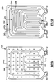
- the cooling plate has three different thermal regions, X, Y, Z, illustrated in Figure 4 .
- 60% of the heat is within the top 40% of the battery cell 12.
- the first and second thermal region X, Y would correspond to the top 40% of the battery cell 12.
- FIG. 4 illustrates the detail of an example cooling plate 20.
- the cooling plate 20 includes inlet and outlet ports 30, 32. Further, the cooling plate 20 has a top side 48, bottom side 50 and lateral sides 52, 54.
- the busbars are arranged at the top side 48, and the inlet and outlet ports are arranged at the bottom side 50.
- the battery cells 12 are hottest near the busbars 16 and coolest on the sides remote from the busbars.
- the first thermal region X is primarily arranged at the top of the cooling plate 20, adjacent to the busbars 16, which generate a significant amount of heat.
- the first cooling channel 42 has a "pi" or inverted U-shape that runs along the lateral side 52 from the inlet port 30 up to the top side 48, then along the lateral side 54 to the outlet port 42.
- the first cooling channel 42 is dedicated to quickly removing heat from the first thermal region X in one pass.
- the second cooling channel 44 is primarily arranged in the second thermal region Y, which is located within the top 40% of the cooling plate 20, but away from the busbars 16.
- the second cooling channel 44 is further positioned within the first cooling channel 42.
- the second cooling channel 44 is serpentine-shaped, here an S-shape, abouta first direction D1, which is generally perpendicular to the lateral sides 52, 54 of the cooling plate 20.
- the second cooling channel 44 runs upward to the first cooling channel 42, turns laterally inwardly, at 41, and then doubles back twice, at 43 and 45, before returning downward to the outlet port 32 at about the halfway point. In this manner, the heat from the top of the cooling plate is used to heat cooler parts of the plate and more evenly distribute heat.
- the third cooling channel 46 is primarily arranged in the third thermal region Z.
- the third cooling channel 46 is serpentine-shaped about a second direction D2, which is generally perpendicular to D1. As shown, the third cooling channel46 is positioned within the second cooling channel 44, and runs from the cooling inlet 30 vertically to about midway up the cooling plate 20 before doubling back several times, at 47, 49 and 51, before returning to the cooling outlet 32.
- the serpentine flow path flows to the warmer part of the cooling plate (near the thermal region Y) to pick up heat and distribute the heat to the coolest part (thermal region Z), near the ports 30, 32.
- the second cooling channel 44 is shown as an S-shape, the second channel could include any number of turns, and is not limited to only including two turns. Further, while the second cooling channel 44 is serpentine-shaped about the first direction D1 extending generally parallel to the lateral sides 52, 54 of the cooling plate 20, the second cooling channel could be oriented in another direction, such as D2. For example, in one embodiment, the second cooling channel 44 is serpentine-shaped about the second direction D2, while still being primarily positioned in the second thermal region Y, and the third cooling channel 46 is serpentine shaped about the first direction D1 while still being primarily positioned in the third thermal region Z.
- first, second and third cooling channels 42, 44, 46 converge in a mixing section 34 near the outlet port 42.
- Each of the first, second and third cooling channels 42, 44, 46 respectively include first, second, third metering orifices 56, 58, 60 that regulate the flow of fluid through each of the respective cooling channels.
- the orifices 56, 58, 60 are sized to achieve a desired relative flow between the cooling channels, which results in achieving a desired temperature gradient across the cooling plate.
- the first cooling channel 42 receives approximately 40% of the flow
- the second cooling channel 44 receives approximately 35% of the flow
- the third cooling channel 46 receives approximately 25% of the flow.
- the term "approximately” includes values within tolerances accepted in this art.
- the size of the orifices 56, 58, 60 also provides a desired pressure drop for each cooling plate 20. This leads to a uniform distribution of coolant between each of the cooling plates 20, at a system level.
- FIG. 5A Another example cooling plate 120 is illustrated in Figure 5A .
- the cooling plate incorporates dimples 62 in the first, second and third cooling channels 142, 144, 146 to provide more structural integrity to the cooling channels.
- each cooling channel may comprise multiple sub-channels.
- the first cooling channel 242 includes first and second sub-channels 242a, 242b;
- second cooling channel 244 includes first and second sub-channels 246a, 246b;
- third cooling channel 246 includes first and second sub-channels 246a, 246b.
- This disclosure thus provides a uniform coolant flow distribution for each battery cell in the battery module.
- This disclosure further provides a desired, localized coolant flow within each battery cell, which efficiently cools each of the cells and further serves to minimize temperature differences within each battery cell, as mentioned above.
Landscapes
- Engineering & Computer Science (AREA)
- Manufacturing & Machinery (AREA)
- Chemical & Material Sciences (AREA)
- Chemical Kinetics & Catalysis (AREA)
- Electrochemistry (AREA)
- General Chemical & Material Sciences (AREA)
- Physics & Mathematics (AREA)
- Algebra (AREA)
- General Physics & Mathematics (AREA)
- Mathematical Analysis (AREA)
- Mathematical Optimization (AREA)
- Pure & Applied Mathematics (AREA)
- Thermal Sciences (AREA)
- Mechanical Engineering (AREA)
- General Engineering & Computer Science (AREA)
- Secondary Cells (AREA)
- Battery Mounting, Suspending (AREA)
Abstract
Description
- Battery modules, such as those used in hybrid vehicles, are known to include multiple battery cells. During operation, the temperature of these battery cells increases, and often the heated battery cells have an uneven temperature gradient. In one known system, cooling plates are provided between battery cells, and coolant flows through apassage in each cooling plate to cool the adjacent battery cells.
- A battery module according to one embodiment of this disclosure includes a battery pack including multiple spaced apart battery cells, and a cooling system having multiple cooling plates providing a cooling plenum. The cooling plates are arranged in an alternating relationship between the battery cells, with each cooling plate including a first cooling channel and a second cooling channel. The first cooling channel has a first shape and is arranged in a first thermal region, and the second cooling channel has a second shape different than the first shape, and is arranged in a second thermal region different than the first thermal region.
- In another embodiment of this disclosure, the cooling plate includes first, second, and third cooling channels. The first cooling channel is provided in a U-shape, and the second cooling channel is provided in a serpentine-shape in a first direction. The third cooling channel is provided in a serpentine-shape in a second direction generally perpendicular to the first direction.
- These and other features of the present disclosure can be best understood from the following drawings and detailed description.
- The drawings can be briefly described as follows:
-
Figure 1 illustrates an example battery module. -
Figure 2 schematically illustrates an example cooling system. -
Figure 3 illustrates a portion of the battery module, in cross section, and in particular illustrates the detail of an example cooling plate. -
Figure 4 illustrates an example cooling plate. -
Figures 5A-5B illustrate further examples of cooling plates. - An
example battery module 10 is illustrated inFigure 1 . Thebattery module 10 includesmultiple battery cells 12 having athermal pad 14 arranged on either side of eachbattery cell 12. Thethermal pads 14 thermally insulate thebattery cells 12 as well as accommodate thermal expansion within thebattery module 10 during operation. - Each
battery cell 12 provides abusbar 16 that connects one voltage terminal (positive or negative) of the cell to the opposite voltage terminal (negative or positive) of theadjacent cell 12. Throughbusbars 16, thecells 12 in thebattery module 10 are electrically connected to one another to power aload 18. Thebusbars 16 are arranged at the top of thebattery module 10. It should be understood, however, that "top," "bottom," "lateral side" and other terms relating to position and orientation are for exemplary purposes only. That is, these terms are used for convenience only and should not be understood as limiting in any way. - A
cooling plate 20 is arranged between each pair ofbattery cells 12. Thecooling plates 20 are joined to one another to provide acooling plenum 22 that is part of acooling system 24, illustrated inFigure 2 . - Turning to
Figure 2 , and with continued reference toFigure 1 , anexample cooling system 24 includes apump 26 that circulates cooling fluid through thecooling system 24. In this example, thepump 26 first circulates the cooling fluid to thecooling plenum 22 to receive heat rejected from thebattery module 10. The heated cooling fluid is then circulated to aheat exchanger 28, which may include afan 29, to reject the heat from the cooling fluid to the surrounding environment. If desired, thecooling system 24 could include additional components, such as an expansion valve. In one example, an expansion valve is positioned upstream of thebattery module 10. - The
cooling plates 20 are provided by first andsecond sheets Figure 3 , that are secured to one another by amaterial 40, such as braze. In one example, the first andsecond sheets - The
cooling plate 20 has at least two channels arranged in two discrete thermal regions having discrete, different flow paths than one another. In one example, the cross-sectional area of the cooling channels is 0.5 mm x 8 mm (0.0196-0.3150 in.). In one example, the cooling plate has three different thermal regions, X, Y, Z, illustrated inFigure 4 . In one battery module arrangement, 60% of the heat is within the top 40% of thebattery cell 12. In such an arrangement, the first and second thermal region X, Y would correspond to the top 40% of thebattery cell 12. -
Figure 4 illustrates the detail of anexample cooling plate 20. Thecooling plate 20 includes inlet andoutlet ports cooling plate 20 has atop side 48,bottom side 50 andlateral sides top side 48, and the inlet and outlet ports are arranged at thebottom side 50. Generally, thebattery cells 12 are hottest near thebusbars 16 and coolest on the sides remote from the busbars. - In the example, the first thermal region X is primarily arranged at the top of the
cooling plate 20, adjacent to thebusbars 16, which generate a significant amount of heat. Thefirst cooling channel 42 has a "pi" or inverted U-shape that runs along thelateral side 52 from theinlet port 30 up to thetop side 48, then along thelateral side 54 to theoutlet port 42. Thefirst cooling channel 42 is dedicated to quickly removing heat from the first thermal region X in one pass. - The second cooling channel 44 is primarily arranged in the second thermal region Y, which is located within the top 40% of the
cooling plate 20, but away from thebusbars 16. The second cooling channel 44 is further positioned within thefirst cooling channel 42. The second cooling channel 44 is serpentine-shaped, here an S-shape, abouta first direction D1, which is generally perpendicular to thelateral sides cooling plate 20. In the example shown, the second cooling channel 44 runs upward to thefirst cooling channel 42, turns laterally inwardly, at 41, and then doubles back twice, at 43 and 45, before returning downward to theoutlet port 32 at about the halfway point. In this manner, the heat from the top of the cooling plate is used to heat cooler parts of the plate and more evenly distribute heat. - The
third cooling channel 46 is primarily arranged in the third thermal region Z. In the illustrated example, thethird cooling channel 46 is serpentine-shaped about a second direction D2, which is generally perpendicular to D1. As shown, the third cooling channel46 is positioned within the second cooling channel 44, and runs from thecooling inlet 30 vertically to about midway up thecooling plate 20 before doubling back several times, at 47, 49 and 51, before returning to thecooling outlet 32. The serpentine flow path flows to the warmer part of the cooling plate (near the thermal region Y) to pick up heat and distribute the heat to the coolest part (thermal region Z), near theports - It should be understood that while the second cooling channel 44 is shown as an S-shape, the second channel could include any number of turns, and is not limited to only including two turns. Further, while the second cooling channel 44 is serpentine-shaped about the first direction D1 extending generally parallel to the
lateral sides cooling plate 20, the second cooling channel could be oriented in another direction, such as D2. For example, in one embodiment, the second cooling channel 44 is serpentine-shaped about the second direction D2, while still being primarily positioned in the second thermal region Y, and thethird cooling channel 46 is serpentine shaped about the first direction D1 while still being primarily positioned in the third thermal region Z. - Turning back to
Figure 4 , the ends of the first, second andthird cooling channels mixing section 34 near theoutlet port 42. Each of the first, second andthird cooling channels third metering orifices - The
orifices first cooling channel 42 receives approximately 40% of the flow, the second cooling channel 44 receives approximately 35% of the flow, and thethird cooling channel 46 receives approximately 25% of the flow. For the purposes of this disclosure, the term "approximately" includes values within tolerances accepted in this art. The size of theorifices plate 20. This leads to a uniform distribution of coolant between each of the coolingplates 20, at a system level. - Another
example cooling plate 120 is illustrated inFigure 5A . The cooling plate incorporatesdimples 62 in the first, second andthird cooling channels - As illustrated in the
cooling plate 220 ofFigure 5B , alternatively or additionally, each cooling channel may comprise multiple sub-channels. In the example, thefirst cooling channel 242 includes first and second sub-channels 242a, 242b;second cooling channel 244 includes first and second sub-channels 246a, 246b; andthird cooling channel 246 includes first and second sub-channels 246a, 246b. - This disclosure thus provides a uniform coolant flow distribution for each battery cell in the battery module. This disclosure further provides a desired, localized coolant flow within each battery cell, which efficiently cools each of the cells and further serves to minimize temperature differences within each battery cell, as mentioned above.
- Although the different examples have the specific components shown in the illustrations, embodiments of this disclosure are not limited to those particular combinations. It is possible to use some of the components or features from one of the examples in combination with features or components from another one of the examples.
- One of ordinary skill in this art would understand that the above-described embodiments are exemplary and non-limiting. That is, modifications of this disclosure would come within the scope of the claims. Accordingly, the following claims should be studied to determine their true scope and content.
Claims (15)
- A battery module comprising:a battery pack including multiple spaced apart battery cells; anda cooling system having multiple cooling plates providing a cooling plenum, the cooling plates arranged in alternating relationship between the battery cells, each cooling plate including a first cooling channel and a second cooling channel, the first cooling channel having a first shape and arranged in a first thermal region, the second cooling channel having a second shape different than the first shape, and the second cooling channel arranged in a second thermal region different than the first thermal region.
- The battery module as recited in claim 1, wherein a third cooling channel has a third shape different than the first shape and the second shape, the third cooling channel arranged in a third thermal region different than the first thermal region and the second thermal region.
- The battery module as recited in claim 2, wherein the first thermal region is proximate to busbars of the battery cells, and the third thermal region is proximate to coolant inlet and outlet ports arranged on a side opposite the busbars.
- The battery module as recited in claim 3 or 4, wherein the first shape is an inverted U-shape, the second shape is a serpentine-shape in a first direction, and the third shape is a serpentine-shape in a second direction generally perpendicular to the first direction.
- The battery module as recited in any preceding claim, including a pump configured to circulate a cooling fluid through the cooling system.
- The battery module as recited in claim 5, including a heat rejecting heat exchanger upstream of the pump and downstream of the battery pack.
- A cooling plate for a battery module comprising:first, second and third cooling channels, respectively including first, second and third shapes that, respectively, provide first, second and third thermal regions, wherein the first second and third thermal regions are different than one another, the third thermal region being proximate a coolant inlet port and a coolant outlet port, the first thermal region being located opposite the third thermal region, wherein the first cooling channel is provided in a U-shape, the second cooling channel is provided in a serpentine-shape about a first direction, and the third cooling channel is provided in a serpentine-shape about a second direction generally perpendicular to the first direction.
- The cooling plate as recited in claim 7, including a first sheet and a second sheet, the first sheet and the second sheet providing the first, second and third cooling channels.
- The cooling plate as recited in claim 8, wherein the first sheet and the second sheet each have a thickness of 0.2-0.5 mm (0.0078-0.0196 in.).
- The cooling plate as recited in claim 7, 8 or 9, wherein the first, second and third cooling channels, respectively, include first, second and third metering orifices adjacent the coolant outlet ports.
- The cooling plate as recited in claim 10, wherein the first cooling channel is sized such the first cooling channel receives approximately 40% of a coolant flow, the second cooling channel 44 receives approximately 35% of the coolant flow, and the third cooling channel receives approximately 25% of the coolant flow.
- The cooling plate as recited in claim 7, 8, 9, 10 or 11, wherein each of the first, second and third cooling channels includes at least one sub-channel.
- The cooling plate as recited in claim 7, 8, 9, 10, 11 or 12, wherein the first cooling channel is provided in an inverted U-shape such that the first cooling channel runs from the coolant inlet port along a lateral side of the cooling plate, along a top side of the cooling plate, and along another lateral side of the cooling plate to the coolant outlet port.
- The cooling plate as recited in claim 13, wherein the second cooling channel is positioned within the first cooling channel, and wherein the first direction is generally perpendicular to the lateral sides of the cooling plate.
- The cooling plate as recited in claim 14, wherein the third cooling channel is positioned within the second cooling channel.
Applications Claiming Priority (2)
| Application Number | Priority Date | Filing Date | Title |
|---|---|---|---|
| US201161549861P | 2011-10-21 | 2011-10-21 | |
| US13/652,530 US8835039B2 (en) | 2011-10-21 | 2012-10-16 | Battery cooling plate and cooling system |
Publications (2)
| Publication Number | Publication Date |
|---|---|
| EP2584644A1 true EP2584644A1 (en) | 2013-04-24 |
| EP2584644B1 EP2584644B1 (en) | 2017-01-11 |
Family
ID=48108867
Family Applications (1)
| Application Number | Title | Priority Date | Filing Date |
|---|---|---|---|
| EP12188890.3A Active EP2584644B1 (en) | 2011-10-21 | 2012-10-17 | Battery cooling plate and cooling system |
Country Status (4)
| Country | Link |
|---|---|
| US (1) | US8835039B2 (en) |
| EP (1) | EP2584644B1 (en) |
| JP (1) | JP6118531B2 (en) |
| CN (1) | CN103066342B (en) |
Cited By (3)
| Publication number | Priority date | Publication date | Assignee | Title |
|---|---|---|---|---|
| GB2516209A (en) * | 2013-02-26 | 2015-01-21 | Williams Grand Prix Eng | Heat Transfer Device |
| CN112146488A (en) * | 2020-09-10 | 2020-12-29 | 山东旺泰科技有限公司 | Silicon carbide plate heat exchanger |
| EP4199192A3 (en) * | 2021-12-16 | 2023-07-26 | Rimac Automobiles Ltd. | Cooling plate of a battery module of a traction battery of a motor vehicle, method for producing the same, and battery module |
Families Citing this family (65)
| Publication number | Priority date | Publication date | Assignee | Title |
|---|---|---|---|---|
| KR101601149B1 (en) * | 2013-10-17 | 2016-03-08 | 주식회사 엘지화학 | Heat sink having 2 or more separated cooling way |
| KR101642326B1 (en) | 2013-10-18 | 2016-07-26 | 주식회사 엘지화학 | Heat sink having 2 or more separated cooling way with vertical placemented common gateway |
| KR101601142B1 (en) * | 2013-10-18 | 2016-03-08 | 주식회사 엘지화학 | Heat sink having 2 or more separated cooling way with insulation material |
| US9452683B2 (en) * | 2014-02-25 | 2016-09-27 | Ford Global Technologies, Llc | Traction battery thermal plate with longitudinal channel configuration |
| US10396411B2 (en) | 2014-02-25 | 2019-08-27 | Ford Global Technologies, Llc | Traction battery thermal plate with transverse channel configuration |
| US9368845B2 (en) * | 2014-02-25 | 2016-06-14 | Ford Global Technologies, Llc | Traction battery thermal plate with multi pass channel configuration |
| EP2916366B1 (en) * | 2014-03-05 | 2018-01-31 | Volvo Car Corporation | Energy storage enclosure |
| CA2960157A1 (en) * | 2014-09-05 | 2016-03-10 | Dana Canada Corporation | Expandable stacked plate heat exchanger for a battery unit |
| DE102014219812A1 (en) * | 2014-09-30 | 2016-03-31 | Robert Bosch Gmbh | Cooling plate for an electrical energy storage |
| US9786969B2 (en) * | 2014-11-11 | 2017-10-10 | Ford Global Technologies, Llc | Magnetically controlled traction battery thermal plate |
| WO2016191881A1 (en) | 2015-06-04 | 2016-12-08 | Dana Canada Corporation | Heat exchanger with regional flow distribution for uniform cooling of battery cells |
| EP3157092B1 (en) | 2015-10-14 | 2020-01-01 | Samsung SDI Co., Ltd. | Battery module including a cooling plate with embedded cooling tubes |
| DE102015118747A1 (en) * | 2015-11-02 | 2017-05-04 | Valeo Klimasysteme Gmbh | Cooling module for a battery, battery for a vehicle and method for manufacturing a cooling module |
| KR102458066B1 (en) * | 2015-11-09 | 2022-10-24 | 엘지이노텍 주식회사 | Cooling pannel and electronic component package including the same |
| US20170194679A1 (en) * | 2015-12-30 | 2017-07-06 | GM Global Technology Operations LLC | Composite Heat Exchanger for Batteries and Method of Making Same |
| CN106058372A (en) * | 2016-08-04 | 2016-10-26 | 上海电机学院 | Heat management system and method for power battery |
| DE102016215850B4 (en) * | 2016-08-23 | 2023-02-16 | Bayerische Motoren Werke Aktiengesellschaft | High-voltage storage for electric or hybrid vehicles and electric or hybrid vehicles |
| US11025034B2 (en) * | 2016-08-31 | 2021-06-01 | Nlight, Inc. | Laser cooling system |
| CN109891666B (en) * | 2016-10-26 | 2022-05-31 | 三星Sdi株式会社 | Battery module |
| CN108072289A (en) * | 2016-11-08 | 2018-05-25 | S&G株式会社 | The one-piece type heat exchanger plate of flow path |
| US10693201B2 (en) * | 2016-12-13 | 2020-06-23 | ThermAvant Technologies, LLC | Thermal management of energy storage devices via oscillating heat pipes |
| FR3061765B1 (en) | 2017-01-06 | 2020-01-24 | Valeo Systemes Thermiques | PLATE FOR HEAT EXCHANGER FOR THE THERMAL REGULATION OF AN ELECTRICAL ENERGY STORAGE UNIT, EXCHANGER AND RELATED BATTERY MODULE |
| DE102017202552A1 (en) * | 2017-02-16 | 2018-08-16 | Reinz-Dichtungs-Gmbh | Radiator plate and method for its production |
| CN106785226A (en) * | 2017-03-16 | 2017-05-31 | 惠州市鼎丰泰科技有限公司 | A kind of heat management system of loop circuit heat pipe and application loop circuit heat pipe |
| GB201705513D0 (en) * | 2017-04-05 | 2017-05-17 | Siemens Ag | Cooling system and method |
| DE102017210185A1 (en) * | 2017-06-19 | 2018-12-20 | Robert Bosch Gmbh | Cooling system with a plurality of elements to be cooled |
| KR102274518B1 (en) * | 2017-09-29 | 2021-07-06 | 주식회사 엘지에너지솔루션 | Cooling jacket having an ununiformed flow channels for cooling an secondary battery cell and battery module including the same |
| CN108054461A (en) * | 2017-12-01 | 2018-05-18 | 国联汽车动力电池研究院有限责任公司 | Flexible packaging power battery liquid cooling plate and battery modules |
| DE102017223476A1 (en) | 2017-12-20 | 2019-06-27 | Elringklinger Ag | Cooling module for a cell stack, cell stack, battery device and method for cooling cells |
| DE102017223474A1 (en) * | 2017-12-20 | 2019-06-27 | Elringklinger Ag | Cooling module for a cell stack, cell stack, battery device and method for cooling cells |
| JP7402808B2 (en) | 2018-03-06 | 2023-12-21 | エーエスエムエル ネザーランズ ビー.ブイ. | Radiation shielding devices and equipment equipped with such shielding devices |
| JP2019175716A (en) * | 2018-03-29 | 2019-10-10 | 株式会社東芝 | Battery pack |
| KR102391984B1 (en) * | 2018-05-23 | 2022-04-27 | 주식회사 엘지에너지솔루션 | Cooling member for battery module and battery pack including the same |
| HUE067897T2 (en) | 2018-06-05 | 2024-11-28 | Outokumpu Oy | Thermal systems for battery electric vehicles |
| KR102643493B1 (en) * | 2018-06-28 | 2024-03-04 | 현대자동차주식회사 | Battery system for vehicle |
| CN110763049B (en) * | 2018-07-26 | 2023-08-08 | 达纳加拿大公司 | Heat exchanger with parallel flow features to enhance heat transfer |
| DE202018004979U1 (en) * | 2018-10-25 | 2020-01-28 | Reinz-Dichtungs-Gmbh | Plate-like liquid container and battery temperature control arrangement |
| US11223081B2 (en) * | 2018-11-14 | 2022-01-11 | Rivian Ip Holdings, Llc | Serpentine counter flow cold plate for a vehicle battery module |
| US10763556B2 (en) | 2018-12-10 | 2020-09-01 | Volvo Car Corporation | Vehicle battery assembly utilizing side cooling plates |
| CN111322794A (en) * | 2018-12-14 | 2020-06-23 | 丹佛斯有限公司 | Heat exchanger and air conditioning system |
| CN111509325A (en) * | 2019-01-30 | 2020-08-07 | 达纳加拿大公司 | Heat exchanger with multi-channel fluid flow passages |
| DE102019105133A1 (en) * | 2019-02-28 | 2020-09-03 | Mahle International Gmbh | Tempering structure |
| FR3097626B1 (en) | 2019-06-20 | 2021-07-09 | Exoes | Thermoregulation system with a rechargeable source of electricity |
| JP7094933B2 (en) * | 2019-11-20 | 2022-07-04 | 本田技研工業株式会社 | Cooler, cooling structure and manufacturing method of cooler |
| DE102019220406B4 (en) * | 2019-12-20 | 2025-09-04 | Hanon Systems | Heat exchanger and heat exchanger arrangement with multiple heat exchangers |
| KR20210125721A (en) * | 2020-04-09 | 2021-10-19 | 주식회사 엘지에너지솔루션 | Battery module and battery pack including the same |
| KR20210130443A (en) * | 2020-04-22 | 2021-11-01 | 주식회사 엘지에너지솔루션 | Battery module and battery pack including the same |
| JP7348145B2 (en) * | 2020-07-10 | 2023-09-20 | 三恵技研工業株式会社 | Battery heat exchange structure |
| US11476517B2 (en) | 2020-09-21 | 2022-10-18 | Rivian Ip Holdings, Llc | Temperature gradient control with thermal interface material variation |
| FI131317B1 (en) | 2021-02-03 | 2025-02-17 | Aurora Powertrains Oy | Scalably structurable battery pack |
| CN115189075B (en) * | 2021-04-01 | 2023-11-03 | 宁德时代新能源科技股份有限公司 | Battery and electric equipment |
| JP7568983B2 (en) * | 2021-05-20 | 2024-10-17 | 日本製鉄株式会社 | Cooling structure, battery unit, and method for manufacturing cooling structure |
| CN115692911B (en) * | 2021-07-30 | 2023-10-20 | 宁德时代新能源科技股份有限公司 | Battery and electricity utilization device |
| EP4239767B1 (en) * | 2022-03-02 | 2024-05-22 | Northvolt AB | A battery system |
| DE102022206659A1 (en) | 2022-06-30 | 2024-01-04 | Mahle International Gmbh | Heat exchanger plate |
| US12159988B2 (en) | 2022-09-14 | 2024-12-03 | Ampaire, Inc. | High efficiency cold plate |
| US11990595B2 (en) | 2022-09-14 | 2024-05-21 | Ampaire, Inc. | High efficiency cold plate |
| KR20250035002A (en) * | 2022-09-29 | 2025-03-11 | 비와이디 컴퍼니 리미티드 | Thermal management system and vehicle equipped therewith |
| JP7833568B2 (en) * | 2022-12-13 | 2026-03-19 | 香港時代新能源科技有限公司 | Batteries and power consumption devices |
| CN218677326U (en) * | 2022-12-13 | 2023-03-21 | 宁德时代新能源科技股份有限公司 | Battery and power consumption device |
| US20240234868A1 (en) * | 2023-01-11 | 2024-07-11 | Ford Global Technologies, Llc | Battery pack including busbar frame configured as coolant manifold |
| US11984571B1 (en) | 2023-01-11 | 2024-05-14 | Beta Air, Llc | Cooling assembly and methods of manufacturing |
| AT527283A1 (en) * | 2023-06-13 | 2024-12-15 | Avl List Gmbh | Battery cell test unit with heating and cooling and battery cell test system |
| EP4589235A1 (en) * | 2024-01-18 | 2025-07-23 | Rimac Technology LLC | Heat exchange assembly |
| JP2025114076A (en) * | 2024-01-24 | 2025-08-05 | Zacros株式会社 | Heat exchange device and battery pack |
Citations (4)
| Publication number | Priority date | Publication date | Assignee | Title |
|---|---|---|---|---|
| EP0964460A1 (en) * | 1998-06-11 | 1999-12-15 | Alcatel | Monobloc battery having a heat exchange device by means of a circulating fluid |
| EP1271085A2 (en) * | 2001-06-23 | 2003-01-02 | Behr GmbH & Co. | Device for cooling vehicle equipment, more particularly battery or fuel cell |
| EP2149771A1 (en) * | 2008-07-29 | 2010-02-03 | Behr GmbH & Co. KG | Device for cooling a heat source of a motor vehicle |
| EP2367220A1 (en) * | 2010-03-05 | 2011-09-21 | MAHLE International GmbH | Cooling element and energy storage device |
Family Cites Families (15)
| Publication number | Priority date | Publication date | Assignee | Title |
|---|---|---|---|---|
| JP3451142B2 (en) * | 1994-11-18 | 2003-09-29 | 本田技研工業株式会社 | Battery assembly with temperature control mechanism |
| DE19528116B4 (en) * | 1995-08-01 | 2007-02-15 | Behr Gmbh & Co. Kg | Heat exchanger with plate sandwich structure |
| US7264901B2 (en) * | 1998-08-23 | 2007-09-04 | Ovonic Battery Company, Inc. | Monoblock battery |
| US6760221B2 (en) * | 2002-10-23 | 2004-07-06 | International Business Machines Corporation | Evaporator with air cooling backup |
| KR20060102851A (en) * | 2005-03-25 | 2006-09-28 | 삼성에스디아이 주식회사 | Secondary battery module |
| KR100790851B1 (en) | 2006-06-09 | 2008-01-02 | 삼성에스디아이 주식회사 | Fuel cell with heat exchanger in stack |
| JP5142605B2 (en) * | 2007-06-28 | 2013-02-13 | 三洋電機株式会社 | Power supply for vehicle |
| JP5147373B2 (en) | 2007-11-29 | 2013-02-20 | 三洋電機株式会社 | Battery system |
| US8845762B2 (en) | 2008-04-09 | 2014-09-30 | GM Global Technology Operations LLC | Batteries and components thereof and methods of making and assembling the same |
| US7851080B2 (en) | 2008-04-09 | 2010-12-14 | Gm Global Technology Operations, Inc. | Battery cooling plate design with discrete channels |
| US8465863B2 (en) * | 2008-04-09 | 2013-06-18 | GM Global Technology Operations LLC | Batteries and components thereof and methods of making and assembling the same |
| US9759495B2 (en) | 2008-06-30 | 2017-09-12 | Lg Chem, Ltd. | Battery cell assembly having heat exchanger with serpentine flow path |
| US20110244297A1 (en) * | 2009-11-03 | 2011-10-06 | Delphi Technologies, Inc. | Prismatic-cell battery pack with integral coolant channels |
| US8039139B2 (en) * | 2009-11-03 | 2011-10-18 | Delphi Technologies, Inc. | Prismatic-cell battery pack with integral coolant passages |
| US8383260B2 (en) | 2010-02-26 | 2013-02-26 | GM Global Technology Operations LLC | U-formed cooling plate with solid fins for lithium pouch cells |
-
2012
- 2012-10-16 US US13/652,530 patent/US8835039B2/en active Active
- 2012-10-17 EP EP12188890.3A patent/EP2584644B1/en active Active
- 2012-10-19 CN CN201210543855.XA patent/CN103066342B/en active Active
- 2012-10-19 JP JP2012232002A patent/JP6118531B2/en active Active
Patent Citations (4)
| Publication number | Priority date | Publication date | Assignee | Title |
|---|---|---|---|---|
| EP0964460A1 (en) * | 1998-06-11 | 1999-12-15 | Alcatel | Monobloc battery having a heat exchange device by means of a circulating fluid |
| EP1271085A2 (en) * | 2001-06-23 | 2003-01-02 | Behr GmbH & Co. | Device for cooling vehicle equipment, more particularly battery or fuel cell |
| EP2149771A1 (en) * | 2008-07-29 | 2010-02-03 | Behr GmbH & Co. KG | Device for cooling a heat source of a motor vehicle |
| EP2367220A1 (en) * | 2010-03-05 | 2011-09-21 | MAHLE International GmbH | Cooling element and energy storage device |
Cited By (4)
| Publication number | Priority date | Publication date | Assignee | Title |
|---|---|---|---|---|
| GB2516209A (en) * | 2013-02-26 | 2015-01-21 | Williams Grand Prix Eng | Heat Transfer Device |
| US10837711B2 (en) | 2013-02-26 | 2020-11-17 | Williams Advanced Engineering Limited | Heat transfer device |
| CN112146488A (en) * | 2020-09-10 | 2020-12-29 | 山东旺泰科技有限公司 | Silicon carbide plate heat exchanger |
| EP4199192A3 (en) * | 2021-12-16 | 2023-07-26 | Rimac Automobiles Ltd. | Cooling plate of a battery module of a traction battery of a motor vehicle, method for producing the same, and battery module |
Also Published As
| Publication number | Publication date |
|---|---|
| EP2584644B1 (en) | 2017-01-11 |
| JP2013101926A (en) | 2013-05-23 |
| US8835039B2 (en) | 2014-09-16 |
| US20130143093A1 (en) | 2013-06-06 |
| CN103066342A (en) | 2013-04-24 |
| CN103066342B (en) | 2016-11-16 |
| JP6118531B2 (en) | 2017-04-19 |
Similar Documents
| Publication | Publication Date | Title |
|---|---|---|
| US8835039B2 (en) | Battery cooling plate and cooling system | |
| US11264658B2 (en) | Heat exchanger with internal cold fluid distribution features for cooling multiple rows of battery cells | |
| US11499790B2 (en) | Heat exchanger with multipass fluid flow passages | |
| US20220131212A1 (en) | Serpentine counter flow cold plate for a vehicle battery module | |
| CN210242511U (en) | Heat exchanger with parallel flow features to enhance heat transfer | |
| US11326837B2 (en) | Heat exchanger with internal manifold structure | |
| US10355331B2 (en) | Heat exchanger with regional flow distribution for uniform cooling of battery cells | |
| US11996533B2 (en) | Utilization of dead channel to improve temperature uniformity on thermal interface material | |
| CN101802536B (en) | Heat exchanger unit and electrochemical energy accumulator comprising a heat exchanger unit | |
| CN213459892U (en) | Heat exchanger | |
| CN112397806B (en) | Battery cold plate integrating heating function, power battery system and new energy vehicle | |
| US12162328B2 (en) | Temperature control device, in particular cooling device for a motor vehicle | |
| WO2021018675A1 (en) | Contra flow channel battery heat exchanger | |
| JP2012190675A (en) | Battery unit | |
| KR20180081996A (en) | Battery Pack having indirect cooling system | |
| JP2012190674A (en) | Battery device | |
| CN216432588U (en) | Thermal regulation device | |
| US20220196347A1 (en) | Temperature control device, in particular a cooling device for a motor vehicle | |
| CN219937170U (en) | Battery pack cooling components, power battery packs and vehicles | |
| WO2022130275A1 (en) | Thermal regulation device | |
| WO2012160573A2 (en) | Battery thermal management arrangement | |
| CN217062264U (en) | Liquid cooling plate of battery pack and battery pack | |
| CN216600594U (en) | Cooling device and temperature-equalizing power assembly | |
| US20250007036A1 (en) | Inter-cell cooling unit for a battery module and battery module for a motor vehicle | |
| WO2020160739A1 (en) | Heat exchangers with improved fluid distribution |
Legal Events
| Date | Code | Title | Description |
|---|---|---|---|
| PUAI | Public reference made under article 153(3) epc to a published international application that has entered the european phase |
Free format text: ORIGINAL CODE: 0009012 |
|
| AK | Designated contracting states |
Kind code of ref document: A1 Designated state(s): AL AT BE BG CH CY CZ DE DK EE ES FI FR GB GR HR HU IE IS IT LI LT LU LV MC MK MT NL NO PL PT RO RS SE SI SK SM TR |
|
| AX | Request for extension of the european patent |
Extension state: BA ME |
|
| 17P | Request for examination filed |
Effective date: 20131016 |
|
| RBV | Designated contracting states (corrected) |
Designated state(s): AL AT BE BG CH CY CZ DE DK EE ES FI FR GB GR HR HU IE IS IT LI LT LU LV MC MK MT NL NO PL PT RO RS SE SI SK SM TR |
|
| RAP1 | Party data changed (applicant data changed or rights of an application transferred) |
Owner name: AVL TEST SYSTEMS, INC. |
|
| 17Q | First examination report despatched |
Effective date: 20151124 |
|
| RAP1 | Party data changed (applicant data changed or rights of an application transferred) |
Owner name: AVL POWERTRAIN ENGINEERING, INC. |
|
| REG | Reference to a national code |
Ref country code: DE Ref legal event code: R079 Ref document number: 602012027658 Country of ref document: DE Free format text: PREVIOUS MAIN CLASS: H01M0010500000 Ipc: F28F0003120000 |
|
| GRAP | Despatch of communication of intention to grant a patent |
Free format text: ORIGINAL CODE: EPIDOSNIGR1 |
|
| RIC1 | Information provided on ipc code assigned before grant |
Ipc: H01M 10/625 20140101ALI20160712BHEP Ipc: H01M 10/617 20140101ALI20160712BHEP Ipc: H01M 10/6557 20140101ALI20160712BHEP Ipc: H01M 10/647 20140101ALN20160712BHEP Ipc: F28F 3/12 20060101AFI20160712BHEP Ipc: H01M 10/613 20140101ALI20160712BHEP Ipc: H01M 10/656 20140101ALI20160712BHEP Ipc: H01M 10/651 20140101ALI20160712BHEP |
|
| INTG | Intention to grant announced |
Effective date: 20160811 |
|
| GRAS | Grant fee paid |
Free format text: ORIGINAL CODE: EPIDOSNIGR3 |
|
| GRAA | (expected) grant |
Free format text: ORIGINAL CODE: 0009210 |
|
| AK | Designated contracting states |
Kind code of ref document: B1 Designated state(s): AL AT BE BG CH CY CZ DE DK EE ES FI FR GB GR HR HU IE IS IT LI LT LU LV MC MK MT NL NO PL PT RO RS SE SI SK SM TR |
|
| REG | Reference to a national code |
Ref country code: GB Ref legal event code: FG4D |
|
| REG | Reference to a national code |
Ref country code: CH Ref legal event code: EP |
|
| REG | Reference to a national code |
Ref country code: AT Ref legal event code: REF Ref document number: 861692 Country of ref document: AT Kind code of ref document: T Effective date: 20170115 |
|
| REG | Reference to a national code |
Ref country code: IE Ref legal event code: FG4D |
|
| REG | Reference to a national code |
Ref country code: DE Ref legal event code: R096 Ref document number: 602012027658 Country of ref document: DE |
|
| REG | Reference to a national code |
Ref country code: LT Ref legal event code: MG4D |
|
| REG | Reference to a national code |
Ref country code: NL Ref legal event code: MP Effective date: 20170111 |
|
| REG | Reference to a national code |
Ref country code: AT Ref legal event code: MK05 Ref document number: 861692 Country of ref document: AT Kind code of ref document: T Effective date: 20170111 |
|
| PG25 | Lapsed in a contracting state [announced via postgrant information from national office to epo] |
Ref country code: NL Free format text: LAPSE BECAUSE OF FAILURE TO SUBMIT A TRANSLATION OF THE DESCRIPTION OR TO PAY THE FEE WITHIN THE PRESCRIBED TIME-LIMIT Effective date: 20170111 |
|
| PG25 | Lapsed in a contracting state [announced via postgrant information from national office to epo] |
Ref country code: HR Free format text: LAPSE BECAUSE OF FAILURE TO SUBMIT A TRANSLATION OF THE DESCRIPTION OR TO PAY THE FEE WITHIN THE PRESCRIBED TIME-LIMIT Effective date: 20170111 Ref country code: LT Free format text: LAPSE BECAUSE OF FAILURE TO SUBMIT A TRANSLATION OF THE DESCRIPTION OR TO PAY THE FEE WITHIN THE PRESCRIBED TIME-LIMIT Effective date: 20170111 Ref country code: GR Free format text: LAPSE BECAUSE OF FAILURE TO SUBMIT A TRANSLATION OF THE DESCRIPTION OR TO PAY THE FEE WITHIN THE PRESCRIBED TIME-LIMIT Effective date: 20170412 Ref country code: FI Free format text: LAPSE BECAUSE OF FAILURE TO SUBMIT A TRANSLATION OF THE DESCRIPTION OR TO PAY THE FEE WITHIN THE PRESCRIBED TIME-LIMIT Effective date: 20170111 Ref country code: NO Free format text: LAPSE BECAUSE OF FAILURE TO SUBMIT A TRANSLATION OF THE DESCRIPTION OR TO PAY THE FEE WITHIN THE PRESCRIBED TIME-LIMIT Effective date: 20170411 Ref country code: IS Free format text: LAPSE BECAUSE OF FAILURE TO SUBMIT A TRANSLATION OF THE DESCRIPTION OR TO PAY THE FEE WITHIN THE PRESCRIBED TIME-LIMIT Effective date: 20170511 |
|
| PG25 | Lapsed in a contracting state [announced via postgrant information from national office to epo] |
Ref country code: PT Free format text: LAPSE BECAUSE OF FAILURE TO SUBMIT A TRANSLATION OF THE DESCRIPTION OR TO PAY THE FEE WITHIN THE PRESCRIBED TIME-LIMIT Effective date: 20170511 Ref country code: ES Free format text: LAPSE BECAUSE OF FAILURE TO SUBMIT A TRANSLATION OF THE DESCRIPTION OR TO PAY THE FEE WITHIN THE PRESCRIBED TIME-LIMIT Effective date: 20170111 Ref country code: AT Free format text: LAPSE BECAUSE OF FAILURE TO SUBMIT A TRANSLATION OF THE DESCRIPTION OR TO PAY THE FEE WITHIN THE PRESCRIBED TIME-LIMIT Effective date: 20170111 Ref country code: LV Free format text: LAPSE BECAUSE OF FAILURE TO SUBMIT A TRANSLATION OF THE DESCRIPTION OR TO PAY THE FEE WITHIN THE PRESCRIBED TIME-LIMIT Effective date: 20170111 Ref country code: BG Free format text: LAPSE BECAUSE OF FAILURE TO SUBMIT A TRANSLATION OF THE DESCRIPTION OR TO PAY THE FEE WITHIN THE PRESCRIBED TIME-LIMIT Effective date: 20170411 Ref country code: PL Free format text: LAPSE BECAUSE OF FAILURE TO SUBMIT A TRANSLATION OF THE DESCRIPTION OR TO PAY THE FEE WITHIN THE PRESCRIBED TIME-LIMIT Effective date: 20170111 Ref country code: SE Free format text: LAPSE BECAUSE OF FAILURE TO SUBMIT A TRANSLATION OF THE DESCRIPTION OR TO PAY THE FEE WITHIN THE PRESCRIBED TIME-LIMIT Effective date: 20170111 Ref country code: RS Free format text: LAPSE BECAUSE OF FAILURE TO SUBMIT A TRANSLATION OF THE DESCRIPTION OR TO PAY THE FEE WITHIN THE PRESCRIBED TIME-LIMIT Effective date: 20170111 |
|
| REG | Reference to a national code |
Ref country code: DE Ref legal event code: R097 Ref document number: 602012027658 Country of ref document: DE |
|
| PG25 | Lapsed in a contracting state [announced via postgrant information from national office to epo] |
Ref country code: RO Free format text: LAPSE BECAUSE OF FAILURE TO SUBMIT A TRANSLATION OF THE DESCRIPTION OR TO PAY THE FEE WITHIN THE PRESCRIBED TIME-LIMIT Effective date: 20170111 Ref country code: EE Free format text: LAPSE BECAUSE OF FAILURE TO SUBMIT A TRANSLATION OF THE DESCRIPTION OR TO PAY THE FEE WITHIN THE PRESCRIBED TIME-LIMIT Effective date: 20170111 Ref country code: IT Free format text: LAPSE BECAUSE OF FAILURE TO SUBMIT A TRANSLATION OF THE DESCRIPTION OR TO PAY THE FEE WITHIN THE PRESCRIBED TIME-LIMIT Effective date: 20170111 Ref country code: SK Free format text: LAPSE BECAUSE OF FAILURE TO SUBMIT A TRANSLATION OF THE DESCRIPTION OR TO PAY THE FEE WITHIN THE PRESCRIBED TIME-LIMIT Effective date: 20170111 Ref country code: CZ Free format text: LAPSE BECAUSE OF FAILURE TO SUBMIT A TRANSLATION OF THE DESCRIPTION OR TO PAY THE FEE WITHIN THE PRESCRIBED TIME-LIMIT Effective date: 20170111 |
|
| PLBE | No opposition filed within time limit |
Free format text: ORIGINAL CODE: 0009261 |
|
| STAA | Information on the status of an ep patent application or granted ep patent |
Free format text: STATUS: NO OPPOSITION FILED WITHIN TIME LIMIT |
|
| PG25 | Lapsed in a contracting state [announced via postgrant information from national office to epo] |
Ref country code: SM Free format text: LAPSE BECAUSE OF FAILURE TO SUBMIT A TRANSLATION OF THE DESCRIPTION OR TO PAY THE FEE WITHIN THE PRESCRIBED TIME-LIMIT Effective date: 20170111 Ref country code: DK Free format text: LAPSE BECAUSE OF FAILURE TO SUBMIT A TRANSLATION OF THE DESCRIPTION OR TO PAY THE FEE WITHIN THE PRESCRIBED TIME-LIMIT Effective date: 20170111 |
|
| 26N | No opposition filed |
Effective date: 20171012 |
|
| PG25 | Lapsed in a contracting state [announced via postgrant information from national office to epo] |
Ref country code: SI Free format text: LAPSE BECAUSE OF FAILURE TO SUBMIT A TRANSLATION OF THE DESCRIPTION OR TO PAY THE FEE WITHIN THE PRESCRIBED TIME-LIMIT Effective date: 20170111 |
|
| PG25 | Lapsed in a contracting state [announced via postgrant information from national office to epo] |
Ref country code: MC Free format text: LAPSE BECAUSE OF FAILURE TO SUBMIT A TRANSLATION OF THE DESCRIPTION OR TO PAY THE FEE WITHIN THE PRESCRIBED TIME-LIMIT Effective date: 20170111 |
|
| REG | Reference to a national code |
Ref country code: CH Ref legal event code: PL |
|
| GBPC | Gb: european patent ceased through non-payment of renewal fee |
Effective date: 20171017 |
|
| REG | Reference to a national code |
Ref country code: IE Ref legal event code: MM4A |
|
| REG | Reference to a national code |
Ref country code: FR Ref legal event code: ST Effective date: 20180629 |
|
| PG25 | Lapsed in a contracting state [announced via postgrant information from national office to epo] |
Ref country code: CH Free format text: LAPSE BECAUSE OF NON-PAYMENT OF DUE FEES Effective date: 20171031 Ref country code: LI Free format text: LAPSE BECAUSE OF NON-PAYMENT OF DUE FEES Effective date: 20171031 Ref country code: GB Free format text: LAPSE BECAUSE OF NON-PAYMENT OF DUE FEES Effective date: 20171017 Ref country code: LU Free format text: LAPSE BECAUSE OF NON-PAYMENT OF DUE FEES Effective date: 20171017 |
|
| REG | Reference to a national code |
Ref country code: BE Ref legal event code: MM Effective date: 20171031 |
|
| PG25 | Lapsed in a contracting state [announced via postgrant information from national office to epo] |
Ref country code: BE Free format text: LAPSE BECAUSE OF NON-PAYMENT OF DUE FEES Effective date: 20171031 Ref country code: FR Free format text: LAPSE BECAUSE OF NON-PAYMENT OF DUE FEES Effective date: 20171031 |
|
| PG25 | Lapsed in a contracting state [announced via postgrant information from national office to epo] |
Ref country code: MT Free format text: LAPSE BECAUSE OF NON-PAYMENT OF DUE FEES Effective date: 20171017 |
|
| PG25 | Lapsed in a contracting state [announced via postgrant information from national office to epo] |
Ref country code: IE Free format text: LAPSE BECAUSE OF NON-PAYMENT OF DUE FEES Effective date: 20171017 |
|
| PG25 | Lapsed in a contracting state [announced via postgrant information from national office to epo] |
Ref country code: HU Free format text: LAPSE BECAUSE OF FAILURE TO SUBMIT A TRANSLATION OF THE DESCRIPTION OR TO PAY THE FEE WITHIN THE PRESCRIBED TIME-LIMIT; INVALID AB INITIO Effective date: 20121017 |
|
| PG25 | Lapsed in a contracting state [announced via postgrant information from national office to epo] |
Ref country code: CY Free format text: LAPSE BECAUSE OF NON-PAYMENT OF DUE FEES Effective date: 20170111 |
|
| PG25 | Lapsed in a contracting state [announced via postgrant information from national office to epo] |
Ref country code: MK Free format text: LAPSE BECAUSE OF FAILURE TO SUBMIT A TRANSLATION OF THE DESCRIPTION OR TO PAY THE FEE WITHIN THE PRESCRIBED TIME-LIMIT Effective date: 20170111 |
|
| PG25 | Lapsed in a contracting state [announced via postgrant information from national office to epo] |
Ref country code: TR Free format text: LAPSE BECAUSE OF FAILURE TO SUBMIT A TRANSLATION OF THE DESCRIPTION OR TO PAY THE FEE WITHIN THE PRESCRIBED TIME-LIMIT Effective date: 20170111 |
|
| PG25 | Lapsed in a contracting state [announced via postgrant information from national office to epo] |
Ref country code: AL Free format text: LAPSE BECAUSE OF FAILURE TO SUBMIT A TRANSLATION OF THE DESCRIPTION OR TO PAY THE FEE WITHIN THE PRESCRIBED TIME-LIMIT Effective date: 20170111 |
|
| P01 | Opt-out of the competence of the unified patent court (upc) registered |
Effective date: 20230508 |
|
| REG | Reference to a national code |
Ref country code: DE Ref legal event code: R081 Ref document number: 602012027658 Country of ref document: DE Owner name: AVL MOBILITY TECHNOLOGIES, INC., PLYMOUTH, US Free format text: FORMER OWNER: AVL POWERTRAIN ENGINEERING, INC., PLYMOUTH, MICH., US |
|
| PGFP | Annual fee paid to national office [announced via postgrant information from national office to epo] |
Ref country code: DE Payment date: 20250819 Year of fee payment: 14 |