EP2584534B1 - Computer-implemented method for creating a virtual 3D model of a real three-dimensional real object and product formed on this basis - Google Patents
Computer-implemented method for creating a virtual 3D model of a real three-dimensional real object and product formed on this basis Download PDFInfo
- Publication number
- EP2584534B1 EP2584534B1 EP12189021.4A EP12189021A EP2584534B1 EP 2584534 B1 EP2584534 B1 EP 2584534B1 EP 12189021 A EP12189021 A EP 12189021A EP 2584534 B1 EP2584534 B1 EP 2584534B1
- Authority
- EP
- European Patent Office
- Prior art keywords
- data
- virtual
- model
- computer
- der
- Prior art date
- Legal status (The legal status is an assumption and is not a legal conclusion. Google has not performed a legal analysis and makes no representation as to the accuracy of the status listed.)
- Active
Links
Images
Classifications
-
- G—PHYSICS
- G06—COMPUTING; CALCULATING OR COUNTING
- G06T—IMAGE DATA PROCESSING OR GENERATION, IN GENERAL
- G06T17/00—Three dimensional [3D] modelling, e.g. data description of 3D objects
- G06T17/10—Constructive solid geometry [CSG] using solid primitives, e.g. cylinders, cubes
-
- G—PHYSICS
- G06—COMPUTING; CALCULATING OR COUNTING
- G06T—IMAGE DATA PROCESSING OR GENERATION, IN GENERAL
- G06T17/00—Three dimensional [3D] modelling, e.g. data description of 3D objects
- G06T17/20—Finite element generation, e.g. wire-frame surface description, tesselation
-
- G—PHYSICS
- G06—COMPUTING; CALCULATING OR COUNTING
- G06T—IMAGE DATA PROCESSING OR GENERATION, IN GENERAL
- G06T19/00—Manipulating 3D models or images for computer graphics
- G06T19/20—Editing of 3D images, e.g. changing shapes or colours, aligning objects or positioning parts
-
- G—PHYSICS
- G06—COMPUTING; CALCULATING OR COUNTING
- G06T—IMAGE DATA PROCESSING OR GENERATION, IN GENERAL
- G06T2200/00—Indexing scheme for image data processing or generation, in general
- G06T2200/08—Indexing scheme for image data processing or generation, in general involving all processing steps from image acquisition to 3D model generation
-
- G—PHYSICS
- G06—COMPUTING; CALCULATING OR COUNTING
- G06T—IMAGE DATA PROCESSING OR GENERATION, IN GENERAL
- G06T2210/00—Indexing scheme for image generation or computer graphics
- G06T2210/41—Medical
-
- G—PHYSICS
- G06—COMPUTING; CALCULATING OR COUNTING
- G06T—IMAGE DATA PROCESSING OR GENERATION, IN GENERAL
- G06T2219/00—Indexing scheme for manipulating 3D models or images for computer graphics
- G06T2219/20—Indexing scheme for editing of 3D models
- G06T2219/2021—Shape modification
Definitions
- the invention relates to a computer-implemented method for generating a virtual 3D model of a three-dimensional real object and to a product formed on this basis.
- Virtual 3D models are widespread objects of artistic and technical creation. These are data sets that define the outer limits (e.g. in the case of grids or 3D mesh) or volumes (in the case of voxels, which represent the three-dimensional Are equivalent to pixels).
- Virtual 3D models can be created on the computer, e.g. B. by technical construction (CAD), by free design using special input aids (e.g. voxel sculpting using a mouse, 3D gloves, etc.) or by capturing real objects with technical means (e.g. imaging methods, in particular MRI, CT, 3D surface scan). The latter method generally allows a multitude of 2D scans to be acquired in layers. Three-dimensional images are generated from this 2D scan and displayed on a computer screen.
- the virtual objects can also be displayed on the basis of a grid model consisting of triangles and / or quads. Editing the same is, however, only possible to a very limited extent, since the Number of nodes is specified and very long bars are created when an node is pulled out excessively, which in turn can no longer be divided and deformed. The resolution of the model in this area becomes too coarse for many purposes.
- Voxel sculpting ie "virtual sculpting" using voxel
- voxel is composed of "volumetric" and "pixel” and in 3D computer graphics denotes a data point of a three-dimensional raster graphic, which corresponds to a pixel in a 2D image.
- voxels are good for representing an equidistantly sampled space that is not filled homogeneously.
- US patent application US2001 / 0033283 A1 discloses a method for identifying and / or manipulating a 3D region from a stack of 2D layers.
- a polygon surface model is generated from structures identified by the user in layers, which is converted into voxel data for further use.
- the invention includes a computer-implemented method, that is to say a method to be carried out on a computer by means of application programs, the intermediate steps specified below being carried out by Selection / participation of the user.
- a computer in the sense of the invention is not necessarily a single device.
- the method can also be carried out on top of one another on various completely independent computers, but also in the scanner itself,
- the method generates a virtual 3D model, i.e. a data set with spatial points (e.g. XYZ or also polar coordinates) and discrete values (e.g. gray levels, color values, radiation values, absorption, reflection) assigned to each of these spatial points of a real three-dimensional real one object.
- Scanners are usually used to record this data. In the present case, this includes in particular scientific, medical, therapeutic and cosmetic imaging methods.
- the scanner is connected to a computer for processing the data, the term computer being understood functionally, that is to say it can also be part of the scanner.
- the invention uses a 3D scanner, which usually generates a plurality of layer-by-layer 2D scans in a pixel format. The object is therefore scanned "pane by pane” and there are a large number of 2D scans, each representing a section through the real object. B. is known from the CT recordings.
- structures are identified in the 2D scans. This is usually done at least partially manually, ie the user marks on the screen the structures that are important for the result of the method, eg. B. the section through an auricle in a slice image.
- the user can have the contrast-enhancing measures known from the image processing area carried out and roughly mark the relevant area around the ear, e.g. B. by means of a freehand line, then the image processing program can analyze the area within the freehand line for the presence of all edges, also known as a "magic wall function".
- the parameters found iteratively by the user in one of the 2D scans can be stored and used for the automatic analysis of the higher and lower 2D scans.
- the user manually analyzes the edges and plots them in the 2D scans.
- the user can also draw the edges in only a 2D scan and the computer analyzes the property of the pixels located in the edges and searches for similar pixels in the higher and lower 2D scans and automatically analyzes them for edges. It is essential that the edges of the respective structures are marked in a suitable manner.
- the 2D scans are each converted from the pixel format into a vector format, the vectors running along the respective edges of the marked structures.
- the relevant structures are therefore converted from the pixel format into a vector format.
- vectorization e.g. B. using "boundary splines” or simple "path formation”.
- the grid is converted into a voxel format to create a virtual solid with the edges of the selected structure as the virtual 3D model. So there is a transition from a vector to a voxel format, i.e. from a shell to a solid body. In this format, virtual processing and movements in the room can be carried out better, e.g. B. by existing voxel editors, i.e. drawing programs for voxel.
- a suitable conversion process is the "Marching Cube Algorithm".
- the voxels or cuboids represented by the voxel data V, Va, Vb preferably have an edge length which is equal to or less than, preferably less than 50% of, the vertical resolution. This results in a virtual 3-D model with little step formation in vertical construction.
- the 3D scan for medical, therapeutic or cosmetic purposes is carried out by means of an imaging method that is customary in this field, in particular CT or MRI or 3D surface scans. So far, and especially the software engineer entrusted with imaging procedures in the medical field, the professional world has not considered using a combination of programs and formats which are used in the artistic and creative field in order to use them to obtain data from the above process the imaging methods mentioned,
- individual data are preferably processed by the user in order to correct incorrect measurements which have occurred during the 3D scan and / or to add missing data, in particular between steps d) and e).
- automated pattern recognition changes in contrast, changes in brightness are used systematically for all layers, in particular in step e) and, if appropriate, g).
- algorithms can be used which can mark the structure in the manner of the "magic wall".
- the object generated in the cases A) - C) is preferably stored in a voxel format and further processed without further conversion in order to avoid loss of accuracy.
- a conversion and storage in a grid format This has the advantage that there are currently a large number of further processing options, all of which are based on known grid formats.
- the virtual object created according to the invention can be used in many ways, be it in virtual space or as a 2D printout of a particular view or 3D printout:
- the created virtual object is preferably printed out in a view. A view is thus put on paper and is used for illustration purposes
- the virtual object can be moved / rotated in the virtual space using a computer program and displayed in the corresponding positions. It serves as an interactive demonstration object and can be viewed from all sides. But it is preferably by means of a molding machine, for. B. in rapid prototyping or CNC, manufactured as a real object. Such a machine enables a three-dimensional "expression" of the virtual object and thus creation of a real three-dimensional object.
- the real three-dimensional object can be a product directly or serve as a positive or negative form for conventional impression processes.
- the created virtual object contains the sizes and proportions of the real object. So real objects can be created that correspond to or fit to the scanned original,
- a scientific, medical, therapeutic or cosmetic product is also claimed, which can be produced using a 3D scan by means of an imaging method that is customary in this field, in particular CT or MRI or 3D surface scans. Conversion of the scan into a voxel format, processing of the same and creation of the product by a molding machine using the processed voxel data and / or using the method according to the invention described above.
Description
Die Erfindung betrifft ein computerimplementiertes Verfahren zum Erzeugen eines virtuellen 3D-Modells eines dreidimensionalen realen Objekts sowie ein auf dieser Grundlage geformtes Produkt.The invention relates to a computer-implemented method for generating a virtual 3D model of a three-dimensional real object and to a product formed on this basis.
Virtuelle 3D-Modelle sind weit verbreitete Objekte künstlerischen und technischen Schaffens, Es handelt sich dabei um Datensätze, die die äußeren Grenzen (z. B. im Fall von Gitternetzen bzw. 3D-Mesh) oder Volumen (im Fall von Voxel, welche das dreidimensionale Äquivalent zu Pixel sind). Virtuelle 3D-Modelle können am Computer erschaffen werden, z. B. durch technisches Konstruieren (CAD), durch freie Formgestaltung unter Nutzung spezieller Eingabehilfen (z. B. Voxel-Sculpting unter Verwendung einer Maus, 3D Handschuhe, etc.) oder aufgrund von der Erfassung real existierender Gegenstände mit technischen Mitteln (z. B. bildgebende Verfahren, insbesondere MRT, CT, 3D-Oberflächenscan). Letzteres Verfahren erlaubt in der Regel eine schichtweise Erfassung einer Vielzahl von 2D-Scans. Aus diesem 2D- Scans werden dreidimensional wirkende Bilder erzeugt und auf dem Bildschirm eines Computers dargestellt. Diese Bilder werden mit vergleichsweise einfachen Verfahren, wie z. B. Voxel-Rendering erzeugt und bilden eine Projektion ohne echte 3D- Informationen, wobei die aufwändige Berechnung der plastisch wirkenden Ansicht nicht in Echtzeit erfolgen kann. Ein Drehen eines mittels CT erzeugten Bildes eines Kopfes durch den Nutzer ist daher nicht spontan möglich. Aus dem gleichen Grund sind auch bildhafte Bearbeitungen der auf dem Bildschirm angezeigten Objekte nicht möglich, beispielsweise kann die Länge der Nase des virtuellen Objekts nicht verändert werden.Virtual 3D models are widespread objects of artistic and technical creation. These are data sets that define the outer limits (e.g. in the case of grids or 3D mesh) or volumes (in the case of voxels, which represent the three-dimensional Are equivalent to pixels). Virtual 3D models can be created on the computer, e.g. B. by technical construction (CAD), by free design using special input aids (e.g. voxel sculpting using a mouse, 3D gloves, etc.) or by capturing real objects with technical means (e.g. imaging methods, in particular MRI, CT, 3D surface scan). The latter method generally allows a multitude of 2D scans to be acquired in layers. Three-dimensional images are generated from this 2D scan and displayed on a computer screen. These images are comparatively simple, such as. B. Voxel rendering creates and form a projection without real 3D information, the complex calculation of the plastic-looking view can not be done in real time. It is therefore not possible for the user to spontaneously rotate an image of a head generated by CT. For the same reason, it is also not possible to edit the objects displayed on the screen, for example the length of the nose of the virtual object cannot be changed.
Die virtuellen Objekte können auch auf Grundlage eines Gittermodells, bestehend aus Triangles und/oder Quads angezeigt werden. Eine Bearbeitung desselben ist allerdings nur sehr begrenzt möglich, da die Anzahl an Knotenpunkten vorgegeben ist und beim exzessiven Herausziehen eines Knotenpunktes sehr lange Gitterstäbe entstehen, welche wiederum nicht mehr unterteilt und verformt werden können. Die Auflösung des Modells in diesem Bereich wird für viele Zwecke zu grob.The virtual objects can also be displayed on the basis of a grid model consisting of triangles and / or quads. Editing the same is, however, only possible to a very limited extent, since the Number of nodes is specified and very long bars are created when an node is pulled out excessively, which in turn can no longer be divided and deformed. The resolution of the model in this area becomes too coarse for many purposes.
Im künstlerischen Bereich ist das Voxel-Sculpting, also das "virtuelle Bildhauen" mittels Voxel verbreitet. Der Begriff Voxel ist zusammengesetzt aus "volumetric" und "pixel" und bezeichnet in der 3D-Computergrafik einen Datenpunkt einer dreidimensionalen Rastergrafik, was einem Pixel in einem 2D Bild entspricht. Im Gegensatz zu der Darstellung mit Gitternetzen, sind Voxel gut bei der Repräsentation eines äquidistant gesampelten Raums, der nicht homogen gefüllt ist. Es gibt Voxeleditoren mit denen man voxelbasierte Modelle selber kreieren bzw. abgespeicherte Modelle verändern kann, ohne dass genaue Abmessungen Gegenstand des Modells sind.Voxel sculpting, ie "virtual sculpting" using voxel, is widespread in the artistic field. The term voxel is composed of "volumetric" and "pixel" and in 3D computer graphics denotes a data point of a three-dimensional raster graphic, which corresponds to a pixel in a 2D image. In contrast to the representation with grids, voxels are good for representing an equidistantly sampled space that is not filled homogeneously. There are voxel editors with which you can create voxel-based models yourself or change saved models without exact dimensions being the subject of the model.
US Patentanmeldung
Aus dem Stand der Technik sind keine computerimplementierten Verfahren zum Erzeugen eines virtuellen 3D-Modells eines realen dreidimensionalen realen Objekts bekannt, mittels denen das mit den üblichen bildgebenden Verfahren erzeugte virtuelle 3D-Modell derart bearbeitet werden kann, dass ein maßgerechtes Produkt auf Grundlage dieses Modells automatisch erzeugt werden kann.No computer-implemented methods for generating a virtual 3D model of a real three-dimensional real object are known from the prior art, by means of which the virtual 3D model generated with the conventional imaging methods can be processed in such a way that a true-to-size product based on this model automatically can be generated.
Es ist daher die Aufgabe der vorliegenden Erfindung, ein verbessertes computerimplementiertes Verfahren zum Erzeugen eines virtuellen 3D-Modells eines realen dreidimensionalen realen Objekts sowie auf dieser Grundlage geformtes Produkt, zu schaffen.It is therefore the object of the present invention to provide an improved computer-implemented method for generating a virtual 3D model of a real three-dimensional real object and a product shaped on this basis.
Diese Aufgabe wird gelöst mit einem Verfahren mit den Merkmalen des Hauptanspruchs. Vorteilhafte Ausgestaltungen sind Gegenstand der Unteransprüche. Ferner wird ein entsprechendes Produkt mit den Merkmalen des nebengeordneten Anspruchs angegeben,This object is achieved with a method with the features of the main claim. Advantageous refinements are the subject of the dependent claims. In addition, a corresponding product with the features of the independent claim is specified,
Die Erfindung beinhaltet ein computerimplementiertes Verfahren, also ein auf einem Computer mittels Anwendungsprogramme durchzuführendes Verfahren, wobei die nachfolgend angegebenen Zwischenschritte durch Auswahl/Mitwirkung des Nutzers durchgeführt werden. Ein Computer im Sinn der Erfindung ist nicht zwingend ein einzelnes Gerät. Das Verfahren kann auch aufeinander aufbauend auf verschiedenen vollkommen unabhängigen Rechnern, aber auch im Scanner selber durchgeführt werden,The invention includes a computer-implemented method, that is to say a method to be carried out on a computer by means of application programs, the intermediate steps specified below being carried out by Selection / participation of the user. A computer in the sense of the invention is not necessarily a single device. The method can also be carried out on top of one another on various completely independent computers, but also in the scanner itself,
Das Verfahren erzeugt ein virtuelles 3D-Modell, also einen Datensatz mit Raumpunkten (z. B. XYZ oder auch Polarkoordinaten) und jedem dieser Raumpunkte zugeordneten diskreten Werten (z. B. Graustufen, Farbwerten, Strahlungswerten, Absorption, Reflektion) eines realen dreidimensionalen realen Objekts. Dabei kommen üblicherweise Scanner zur Erfassung dieser Daten zum Einsatz. Vorliegend sind davon insbesondere wissenschaftliche, medizinische, therapeutische und kosmetische bildgebende Verfahren umfasst, Zur Verarbeitung der Daten ist der Scanner mit einem Computer verbunden, wobei der Begriff Computer funktionell zu verstehen ist, also auch Bestandteil des Scanners sein kann.The method generates a virtual 3D model, i.e. a data set with spatial points (e.g. XYZ or also polar coordinates) and discrete values (e.g. gray levels, color values, radiation values, absorption, reflection) assigned to each of these spatial points of a real three-dimensional real one object. Scanners are usually used to record this data. In the present case, this includes in particular scientific, medical, therapeutic and cosmetic imaging methods. The scanner is connected to a computer for processing the data, the term computer being understood functionally, that is to say it can also be part of the scanner.
Die Erfindung benutzt einen 3D-Scanner, weicher üblicherweise eine Mehrzahl von schichtweisen 2D-Scans in einem Pixelformat erzeugt. Das Objekt wird also "Scheibe für Scheibe" gescant und es ergeben sich eine Vielzahl von 2D-Scans, die jeweils einen Schnitt durch das reale Objekt repräsentieren, wie ist z. B. von den CT- Aufnahmen bekannt ist.The invention uses a 3D scanner, which usually generates a plurality of layer-by-layer 2D scans in a pixel format. The object is therefore scanned "pane by pane" and there are a large number of 2D scans, each representing a section through the real object. B. is known from the CT recordings.
In einem weiteren Schritt werden in den 2D-Scans Strukturen identifiziert. Dies erfolgt in der Regel zumindest teilweise manuell, d. h. der Benutzer markiert am Bildschirm die für das Ergebnis des Verfahrens wichtigen Strukturen, z. B. den Schnitt durch eine Ohrmuschel in einer Schichtaufnahme. Dem Fachmann werden dazu eine Vielzahl von Methoden einfallen. Z. B. kann der Nutzer die aus dem Bildbearbeitungsbereich bekannten kontrastverstärkenden Maßnahmen durchführen lassen und den relevanten Bereich um das Ohr herum grob markieren, z. B. mittels einer Freihandlinie, Sodann kann das Bildbearbeitungsprogramm den innerhalb der Freihandlinie liegenden Bereich auf das Vorhandensein von allen Rändern analysieren, auch bekannt als "Magic-Wand-Funktion". Gegebenenfalls können dabei die vom Benutzer iterativ in einem der 2D-Scans herausgefunden Parameter abgespeichert und zur automatischen Analyse der höher und tiefer liegenden weiteren 2D-Scans herangezogen werden. Alternativ ist es auch möglich, dass der Nutzer manuell die Ränder analysiert und in den oder die 2D-Scans einzeichnet. Der Nutzer kann auch in nur einem 2D-Scan die Ränder einzeichnen und der Computer analysiert die Eigenschaft der in den Rändern liegenden Bildpunkte und sucht in den höher und tiefer liegenden übrigen 2D-Scans nach ähnlichen Bildpunkten und analysiert diese automatisch nach Rändern. Wesentlich ist, dass auf eine zweckmäßige Weise die Ränder der jeweiligen Strukturen markiert werden.In a further step, structures are identified in the 2D scans. This is usually done at least partially manually, ie the user marks on the screen the structures that are important for the result of the method, eg. B. the section through an auricle in a slice image. A multitude of methods for this will occur to the person skilled in the art. For example, the user can have the contrast-enhancing measures known from the image processing area carried out and roughly mark the relevant area around the ear, e.g. B. by means of a freehand line, then the image processing program can analyze the area within the freehand line for the presence of all edges, also known as a "magic wall function". If necessary, the parameters found iteratively by the user in one of the 2D scans can be stored and used for the automatic analysis of the higher and lower 2D scans. Alternatively it is possible that the user manually analyzes the edges and plots them in the 2D scans. The user can also draw the edges in only a 2D scan and the computer analyzes the property of the pixels located in the edges and searches for similar pixels in the higher and lower 2D scans and automatically analyzes them for edges. It is essential that the edges of the respective structures are marked in a suitable manner.
In einem weiteren Schritt werden die 2D-Scans jeweils aus dem Pixelformat in ein Vektorformat konvertiert, wobei die Vektoren entlang der jeweiligen Ränder der markierten Strukturen verlaufen. Es findet also eine Umwandlung der relevanten Strukturen aus dem Pixelformat in ein Vektorformat statt. Zur Vektorisierung kennt der Fachmann zahlreiche Verfahren, z. B. unter Nutzung von "Boundary Splines" oder der einfachen "Pfadbildung".In a further step, the 2D scans are each converted from the pixel format into a vector format, the vectors running along the respective edges of the marked structures. The relevant structures are therefore converted from the pixel format into a vector format. The person skilled in the art knows numerous methods for vectorization, e.g. B. using "boundary splines" or simple "path formation".
Sodann wird mittels üblicher automatischer Verfahren ein Gitternetz in die jeweiligen Ränder der geschichteten vektorisierten 2D-Scans gelegt, wobei das Gitternetz die geschichteten 2D-Scans in vertikaler Richtung verbindet. Es entsteht also ein sogenanntes 3D-Mesh.Then, using conventional automatic methods, a grid is placed in the respective edges of the layered vectorized 2D scans, the grid connecting the layered 2D scans in the vertical direction. This creates a so-called 3D mesh.
in einem weiteren Schritt wird das Gitternetz in ein Voxelformat konvertiert zur Schaffung eines virtuellen Festkörpers mit den Rändern der ausgewählten Struktur als das virtuelle 3D-Modell. Es findet also ein Übergang von einem Vektor- in ein Voxelformat, also von einer Hülle zu einem massiven Körper, statt. In diesem Format können virtuelle Bearbeitungen und Bewegungen im Raum besser durchgeführt werden, z. B. durch vorhandene Voxel-Editoren, also Zeichenprogramme für Voxel. Ein geeignetes Konvertierungsverfahren ist der "Marching Cube Algorithm".In a further step, the grid is converted into a voxel format to create a virtual solid with the edges of the selected structure as the virtual 3D model. So there is a transition from a vector to a voxel format, i.e. from a shell to a solid body. In this format, virtual processing and movements in the room can be carried out better, e.g. B. by existing voxel editors, i.e. drawing programs for voxel. A suitable conversion process is the "Marching Cube Algorithm".
Bei den oben geschilderten Konvertierungen ist stets darauf zu achten, dass die Dimensionen, also Maße, seit dem Scan stets mitgeführt werden. Die Auflösung des 3D-Scanners ist bekannt, auch wenn dieser mit Polarkoordinaten arbeitet. Ferner ist der Abstand von Schicht zu Schicht bekannt, selbst wenn diese nicht parallel zueinander liegen (z. B. bei Polarkoordinaten).With the conversions described above, it must always be ensured that the dimensions, i.e. dimensions, have always been carried along since the scan. The resolution of the 3D scanner is known, even if it works with polar coordinates. Furthermore, the distance from layer to layer is known, even if these are not parallel to one another (e.g. in the case of polar coordinates).
Bevor konkrete Nutzungen des erfindungsgemäß hergestellten der virtuellen 3D-Modells beschrieben werden, erfolgt eine detailliertere Formulierung des oben beschriebenen Verfahrens. Dabei werden die folgenden Schritte durchgeführt, wobei lediglich zum besseren Verständnis der Zeichen auf die
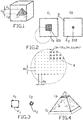
- a. Schichtweise Durchführung eines 3D-Scans mittels des Scanners mittels mehrerer 2D-Scans über mehrere Schichten E1, E2 des realen Objekts mit einer definierten Horizontalauflösung dX, dY in den Ebenen der Schichten und einer definierten Vertikalauflösung dZ senkrecht zur Ebene der Schichten, welche dem Abstand zwischen zwei benachbarten Schichten entspricht.
Der inFigur 1 dargestellte Würfel aus einem ersten Material beinhaltet eine Struktur S als reales 3D-Objekt aus einem zweiten Material in Form einer Pyramide. Der Würfel wird nun mittels eines bildgebenden Verfahrens, z. B. Ultraschall, schichtweise abgescant. Die vertikale Auflösung ist hier der Abstand zwischen zwei Schichten. - b. Erzeugung und Speichern eines Datensatzes D mit XYZ-Koordinaten und dazugehörigen beim Scan gescanten diskreten Werten W je XYZ-Koordinate auf dem Computer.
Der diskrete Wert W entspricht dabei einer Eigenschaft des realen Objekts an der jeweiligen Koordinate. Diese muss nicht zwingend als katesische Koordinate im Format X,Y,Z vorliegen und es ist ausreichend, dass lediglich die Position im Raum eindeutig definiert ist, Vorzugsweise werden lediglich die vom Scanner kommenden Rohdaten weiterverarbeitet, d. h. es findet vorzugsweise keine Kompression statt. - c. Auswählen einer Schicht E1 aus den gescanten SchichtenE1, E2 durch den Nutzer am Computers.
Der Nutzer sucht nun eine geeignete Schicht, also einen 2D-Schnitt aus, der eine für das Verfahren relevante Struktur gut darstellt. Diese 2D-Schnitte sind inFigur 2 dargestellt und zeigen den Würfel als äußeren Rand und den darin liegenden Schnitt durch die Pyramide in unterschiedlichen Ebenen. - d. Bildhaftes Darstellen eines Teildatensatzes D1 aus dem Datensatzes D, welcher der vom Nutzer ausgewählten Schicht E1 zugeordnet ist durch den Computer.
Dem Nutzer wird nun die ausgewählte Ebene angezeigt, wie z. B. inFigur 2 , links dargestellt. - e. Auswählen einer bestimmten Struktur S, welche Bestandteil des zu erzeugenden virtuellen 3D-Modells sein soll in der auf dem Computer dargestellten ausgewählten Schicht durch den Nutzer.
Der Nutzer wählt nun die ihn Interessierende Struktur S, nämlich den Schnitt durch die Pyramide in der ausgewählten Schicht aus. - f. Speichern derjenigen zur Struktur S in der ausgewählten Schicht E1 gehörenden Strukturdaten DS1 aus dem Datensatz D durch den Computer.
Durch geeignete manuelle oder automatische Verfahren, welche oben bereits erläutert wurden, werden die in der konkreten Ansicht zur Struktur gehörenden Daten markiert und gespeichert. Der Begriff "Speichern" ist hier funktionell zu verstehen, d. h. das Computerprogramm muss zumindest für interne Zwecke eine Zwischenspeicherung durchführen. - g. Durchsuchen der restlichen Datensätze D2 nach vergleichbaren zur Struktur S in den nicht-ausgewählten Schichten E2 gehörenden Daten durch den Computer und Speichern der gefundenen Daten als Strukturdaten DS2 durch den Computer.
Wie bereits oben ausgeführt, kann nun manuell oder automatisch eine Markierung und Speicherung der zur Struktur gehörenden Daten in den anderen Schichten erfolgen. Dabei kann das Computerprogramm auf Eigenschaften der in Schritt f) markierten Bildpunkte zurückgreifen, - h. Vorzugsweise erfolgt eine Wiederholung der Schritte c) - g) oder d) - g) oder e) - g) mit weiteren ausgewählten Strukturen Sa, Sb und dabei Erzeugung weiterer Strukturdaten DSa1, DSa2, DSb1, DSb2.
Darunter ist zu verstehen, dass möglicherweise eine Vielzahl von Strukturen vorhanden sind, also z. B. im Inneren der inFigur 1 dargestellte Pyramide eine weitere Struktur, z. B. eine Kugel, versteckt ist. Sofern diese weitere Struktur für das Verfahren von Interesse ist, wird auch diese auf zweckmäßige Art markiert, erkannt und gespeichert. - i. Schichtweise Konvertierung der Ränder der Strukturdaten DS1, DS2 in Vektordaten V1, V2 in jeder Schicht E1, E2, wobei die Vektordaten V1, V2 auch den diskreten Wert W der ausgewählten Struktur beinhalten können.
Dieser Schritt umfasst eine Erkennung der Ränder der einzelnen Strukturen in der jeweiligen Ebene, also z. B. den Rand des Quadrates der Pyramide inFigur 2 , links. Dabei werden die Ränder R vektorisiert, wie bereits oben erläutert. Die Vektoren V1, V2 in den Ebenen E1, E2 zeigtFigur 3 . - j. Falls Schritt h) durchgeführt wurde: Wiederholung von Schritt i) mit den weiteren Strukturdaten DSa1, DSa2, DSb1, DSb2 und dabei Erzeugung weiterer Vektordaten VSa1, VSa2, VSb1, VSb2.
Dieser Schritt bezieht sich auf den Sonderfall, dass eine Vielzahl von Strukturen für die Durchführung des Verfahrens von Relevanz sind. - k. Errechnen von Netzdaten N, weiche ein virtuelles Gitternetz repräsentieren, welches durch die mit dem Abstand der vertikalen Auflösung dZ gestapelten Vektordaten V1, V2 verläuft, so dass das Gitternetz die Hülle der ausgewählten Struktur bildet; wobei die Netzdaten N auch den diskreten Wert W der ausgewählten Struktur beinhalten können.
Die einzelnen Schichten werden nunmehr so wie ursprünglich im Raum übereinander angeordnet und mit einem 3D-Mesh versehen, welches durch die Vektoren bzw. Knotenpunkte derselben verläuft. Das Netz wird nicht als eine Hülle über die Vektoren, sondern in die Vektoren gelegt. Durch Berücksichtigung der vertikalen Auflösung, erhält man ein Netz, welches auch die Höhe des realen abgescanten Objekts repräsentiert; sieheFigur 4 . - l. Falls Schritt h) durchgeführt wurde: Wiederholung von Schritt k) mit den weiteren Vektordaten VSa1, VSa2, VSb1, VSb2 und dabei Erzeugung weiterer Netzdaten Na, Nb
Dieser Schritt bezieht sich auf den Sonderfall, dass eine Vielzahl von Strukturen für die Durchführung des Verfahrens von Relevanz sind. - m. Konvertierung der Netzdaten N in Voxeldaten V zur Schaffung eines virtuellen Festkörpers mit den Grenzen der ausgewählten Struktur S, wobei die Voxeldaten V auch den diskreten Wert W der ausgewählten Struktur beinhalten können.
Auf Basis von Voxeldaten kann der virtuelle Körper besser dargestellt und bearbeitet werden. - n. Falls Schritt h) durchgeführt wurde: Wiederholung von Schritt m) mit den weiteren Netzdaten Na, Nb und dabei Erzeugung weiterer Voxeldaten Va, Vb zur Schaffung weiterer virtueller Festkörper mit den Rändern der weiteren Strukturen Sa, Sb,
Dieser Schritt bezieht sich auf den Sonderfall, dass eine Vielzahl von Strukturen für die Durchführung des Verfahrens von Relevanz sind. - o. Speichern der Voxeldaten V, V1, V2 als das virtuelle 3D-Modell.
Zur weiteren Bearbeitung ist es zweckmäßig, die mit dem erfindungsgemäßen Verfahren erzeugten Voxeldaten zwischenzuspeichern.
- a. Performing a 3D scan layer by layer using the scanner using several 2D scans over several layers E1, E2 of the real object with a defined horizontal resolution dX, dY in the layers of the layers and a defined vertical resolution dZ perpendicular to the layer layer, which is the distance between corresponds to two adjacent layers.
The inFigure 1 The illustrated cube made of a first material contains a structure S as a real 3D object made of a second material in the form of a pyramid. The cube is now using an imaging method, for. B. ultrasound, scanned in layers. The vertical resolution here is the distance between two layers. - b. Generation and storage of a data record D with XYZ coordinates and associated discrete values W scanned during the scan per XYZ coordinate on the computer.
The discrete value W corresponds to a property of the real object at the respective coordinate. This does not necessarily have to be in the form of a Katesic coordinate in the format X, Y, Z and it is sufficient that only the position in space is clearly defined. Preferably only the raw data coming from the scanner are processed further, ie there is preferably no compression. - c. The user selects a layer E1 from the scanned layers E1, E2 on the computer.
The user is now looking for a suitable layer, i.e. a 2D section, which shows a structure relevant to the method. These 2D cuts are inFigure 2 shown and show the cube as outer Edge and the section through the pyramid in different levels. - d. Pictorial representation of a partial data record D1 from the data record D, which is assigned to the layer E1 selected by the user, by the computer.
The user is now shown the selected level, such as B. inFigure 2 , shown on the left. - e. The user selects a specific structure S which is to be part of the virtual 3D model to be generated in the selected layer displayed on the computer.
The user now selects the structure S that interests him, namely the section through the pyramid in the selected layer. - f. The computer stores the structural data DS1 belonging to the structure S in the selected layer E1 from the data record D.
The data belonging to the structure in the concrete view are marked and saved by suitable manual or automatic methods, which have already been explained above. The term "save" is to be understood functionally here, ie the computer program must carry out temporary storage at least for internal purposes. - G. Searching the remaining data records D2 for comparable data belonging to the structure S in the non-selected layers E2 by the computer and storing the found data as structure data DS2 by the computer.
As already explained above, the data belonging to the structure can now be marked manually or automatically in the other layers. The computer program can Use the properties of the pixels marked in step f), - H. Steps c) - g) or d) - g) or e) - g) are preferably repeated with further selected structures Sa, Sb and thereby generating further structure data DSa1, DSa2, DSb1, DSb2.
This means that there may be a multitude of structures, e.g. B. inside the inFigure 1 pyramid shown another structure, e.g. B. a ball is hidden. If this additional structure is of interest to the method, it is also marked, recognized and stored in a suitable manner. - i. Layer-by-layer conversion of the edges of the structure data DS1, DS2 into vector data V1, V2 in each layer E1, E2, wherein the vector data V1, V2 can also contain the discrete value W of the selected structure.
This step includes a detection of the edges of the individual structures in the respective level, that is, e.g. B. the edge of the square of the pyramid inFigure 2 , Left. The edges R are vectorized, as already explained above. The vectors V1, V2 in the levels E1, E2 showsFigure 3 , - j. If step h) was carried out: repetition of step i) with the further structural data DSa1, DSa2, DSb1, DSb2 and thereby generation of further vector data VSa1, VSa2, VSb1, VSb2.
This step refers to the special case that a large number of structures are relevant for the implementation of the procedure. - k. Calculation of network data N, which represent a virtual grid which runs through the vector data V1, V2 stacked with the spacing of the vertical resolution dZ, so that the grid forms the envelope of the selected structure; the network data N can also contain the discrete value W of the selected structure.
The individual layers are now as they were originally in space arranged one above the other and provided with a 3D mesh which runs through the vectors or nodes thereof. The net is not placed as a shell over the vectors, but in the vectors. By taking the vertical resolution into account, a network is obtained which also represents the height of the real scanned object; please referFigure 4 , - l. If step h) was carried out: repetition of step k) with the further vector data VSa1, VSa2, VSb1, VSb2 and thereby generation of further network data Na, Nb
This step refers to the special case that a large number of structures are relevant for the implementation of the procedure. - m. Conversion of the network data N into voxel data V to create a virtual solid with the boundaries of the selected structure S, wherein the voxel data V can also contain the discrete value W of the selected structure.
Based on voxel data, the virtual body can be better displayed and edited. - n. If step h) was carried out: repetition of step m) with the further network data Na, Nb and thereby generation of further voxel data Va, Vb to create further virtual solid bodies with the edges of the further structures Sa, Sb,
This step refers to the special case that a large number of structures are relevant for the implementation of the procedure. - o. Save the voxel data V, V1, V2 as the virtual 3D model.
For further processing, it is expedient to temporarily store the voxel data generated using the method according to the invention.
Vorzugsweise haben die durch die Voxeldaten V, Va, Vb repräsentierten Voxel oder Quader eine Kantenlänge, die gleich oder kleiner, vorzugsweise weniger als 50% der vertikalen Auflösung sind. Dies ergibt ein virtuelles 3-D-Modell mit geringer Stufenbildung in vertikaler Errichtung Erfindungsgemäß erfolgt der 3D-Scan zu medizinischen, therapeutischen oder kosmetischen Zwecken mittels eines auf diesem Gebiet üblichen bildgebenden Verfahrens, insbesondere CT oder MRT oder 3D-Oberflächenscans. Bisher hat die Fachwelt, und das ist insbesondere der mit bildgebenden Verfahren auf dem medizinischen Bereich betraute Softwareingenieur nicht in Betracht gezogen, eine Kombination von Programmen und Formaten, welche im künstlerischen und kreativen Bereich Einsatz finden, zu nutzen, um mit ihnen Daten aus den oben genannten bildgebenden Verfahren zu verarbeiten,The voxels or cuboids represented by the voxel data V, Va, Vb preferably have an edge length which is equal to or less than, preferably less than 50% of, the vertical resolution. This results in a virtual 3-D model with little step formation in vertical construction. According to the invention, the 3D scan for medical, therapeutic or cosmetic purposes is carried out by means of an imaging method that is customary in this field, in particular CT or MRI or 3D surface scans. So far, and especially the software engineer entrusted with imaging procedures in the medical field, the professional world has not considered using a combination of programs and formats which are used in the artistic and creative field in order to use them to obtain data from the above process the imaging methods mentioned,
Vorzugsweise werden in einem oder mehreren der 2D-Scans vom Nutzer einzelne Daten bearbeitet, um beim 3D-Scan aufgetretene Fehlmessungen zu korrigieren und/oder fehlende Daten zu ergänzen, insbesondere zwischen den Schritten d) und e). Es ergibt sich also die Möglichkeit, in einzelnen oder allen Schichten auftretende Fehler oder Ungenauigkeiten zu korrigieren. Darunter wird auch verstanden, dass systematisch für alle Schichten, insbesondere im Schritt e) und gegebenenfalls g) automatisierte Mustererkennungen, Kontrastveränderungen, Helligkeitsveränderungen zum Einsatz kommen. Dabei können insbesondere solche Algorithmen genutzt werden, die nach Art der "Magic Wand" die Struktur markieren können.In one or more of the 2D scans, individual data are preferably processed by the user in order to correct incorrect measurements which have occurred during the 3D scan and / or to add missing data, in particular between steps d) and e). This results in the possibility of correcting errors or inaccuracies occurring in individual layers or in all layers. This also means that automated pattern recognition, changes in contrast, changes in brightness are used systematically for all layers, in particular in step e) and, if appropriate, g). In particular, algorithms can be used which can mark the structure in the manner of the "magic wall".
Korrekturen von Fehlern oder fehlenden Elementen sind grundsätzlich während allen Schritten, in denen Schichtbilder oder bereits das virtuelle Modell angezeigt werden, möglich.Corrections of errors or missing elements are fundamentally possible during all steps in which slice images or the virtual model are already displayed.
Nach der Erstellung eines Voxelmodels, also des virtuellen 3D-Modells, kann dieses auf vielfältige Weise eingesetzt werden, um zu einem virtuellen Modell zu gelangen, Dabei kommt es auf die Art der Anwendung an, wobei grundsätzlich drei Fälle unterschieden werden können,
- A) Das geschaffene virtuelle 3D-Modell kann unmittelbar als virtuelles Objekt dienen und bedarf keiner weiteren Bearbeitung, Z. B. kann der Schädelknochen einer Mumie die relevante Struktur sein und mit dem erfindungsgemäßen Verfahren zum virtuellen 3D-Model werden. Dieser kann nun real, mit realen Maßen, im Rapid-Prototyping-Verfahren oder CNC ausgedruckt werden,
- B) Das geschaffene virtuelle 3D-Modell kann z. B. mittels eines Sculpting-Programms durch den Nutzer in seiner virtuellen Gestalt verändert werden unter Nutzung der Voxeldaten. Die veränderte Gestalt dient als virtuelles Objekt. Damit können z. B. fehlende oder deformierte Stellen, die bereits am realen Objekt vorhanden waren, ausgebessert werden. Dabei kann es sich beispielsweise um eine künstlerische Bearbeitung handeln.
- C) An das geschaffene virtuelle 3D-Modell, welches auch durch den Nutzer in seiner virtuellen Gestalt verändert worden sein kann, wird ein neues Objekt angeformt unter Nutzung der Voxeldaten. Es wird also an das virtuelle 3D-Modell etwas angeformt. Z. B. können im virtuellen 3D-Modell eines defekten Schädels die fehlenden Teile ergänzt und modelliert werden. Das angeformte neue Objekt dient dann als virtuelles Objekt, z. B. als Epithese. Die Anformung kann dabei frei gestaltet werden, d. h. nach ästhetischem Empfinden des Nutzers. Sie kann aber auch dadurch entstehen, dass Referenzobjekte als weitere virtuelle 3D-Modelle zur Verfügung stehen und diese die Basis für das angeformte neue Objekt bilden. So können z. B. individuelle Brustprothesen für Mammakarzinompatientinnen geschaffen werden, wobei das virtuelle 3D-Modell die amputierte Situation darstellt und ein weiteres virtuelles 3D-Modell der Brust vor der Amputation als Referenzobjekt dient zur Erzeugung des angefochtenen neuen Objekts. Als Referenzobjekt kann in diesem Fall auch die Spiegelung eines weiteren 3D-Modells der noch vorhandenen Brust dienen.
- A) The created virtual 3D model can serve directly as a virtual object and requires no further processing, for example the skull bone of a mummy can be the relevant structure and can become a virtual 3D model using the method according to the invention. This can now be printed out real, with real dimensions, using the rapid prototyping process or CNC,
- B) The created virtual 3D model can e.g. B. by means of a sculpting program by the user in its virtual form using the voxel data. The changed shape serves as a virtual object. So z. B. missing or deformed areas that already existed on the real object can be repaired. This can be, for example, an artistic treatment.
- C) A new object is molded onto the created virtual 3D model, which may also have been changed by the user in its virtual form, using the voxel data. So something is molded onto the virtual 3D model. For example, the missing parts can be added and modeled in the virtual 3D model of a defective skull. The molded new object then serves as a virtual object, e.g. B. as an epithesis. The molding can be designed freely, ie according to the aesthetic perception of the user. However, it can also arise from the fact that reference objects are available as additional virtual 3D models and these form the basis for the molded new object. So z. B. individual breast prostheses for breast cancer patients are created, the virtual 3D model representing the amputated situation and another virtual 3D model of the breast before the amputation is used as a reference object to generate the contested new object. In this case, the reflection of another 3D model of the breast still present can also serve as a reference object.
Vorzugsweise wird das in dem Fällen A) - C) generierte Objekt in einem Voxelformat abgespeichert und ohne weitere Konvertierung weiterverarbeitet, um Genauigkeitsverluste zu vermeiden. Alternativ erfolgt jedoch eine Konvertierung und Speicherung in ein Gitternetzformat. Dies hat den Vorteil, dass es derzeit eine Vielzahl von Weiterverarbeitungsmöglichkeiten gibt, die alle auf bekannten Gitternetzformaten basieren. Vorteilhafterweise erfolgt eine Konvertierung in ein für das jeweilige Ausgabegerät, z. B. Drucker, Formmaschine, etc geeignetes Format.The object generated in the cases A) - C) is preferably stored in a voxel format and further processed without further conversion in order to avoid loss of accuracy. Alternatively however, a conversion and storage in a grid format. This has the advantage that there are currently a large number of further processing options, all of which are based on known grid formats. Advantageously, a conversion into a for the respective output device, for. B. printer, molding machine, etc. suitable format.
Das erfindungsgemäß erzeugte virtuelle Objekt kann auf vielerlei Art genutzt werden, sei es im virtuellen Raum oder als 2D-Ausdruck einer bestimmten Ansicht oder 3D-Ausdruck:
Vorzugsweise wird das geschaffene virtuelle Objekt in einer Ansicht ausgedruckt. Eine Ansicht wird somit zu Papier gebracht und dient zu IllustrationszweckenThe virtual object created according to the invention can be used in many ways, be it in virtual space or as a 2D printout of a particular view or 3D printout:
The created virtual object is preferably printed out in a view. A view is thus put on paper and is used for illustration purposes
Das virtuelle Objekt kann mittels eines Computerprogramms im virtuellen Raum bewegt/gedreht und in den entsprechenden Positionen angezeigt werden. Es dient als interaktives Demonstrationsobjekt und kann von allen Seiten betrachtet werden. Vorzugsweise wird es aber mittels einer Formmaschine, z. B. im Rapid-Prototyping oder CNC, als reales Objekt hergestellt. Eine derartige Maschine ermöglicht einen dreidimensionalen "Ausdruck" des virtuellen Objektes und somit Schaffung eines realen dreidimensionalen Objektes. Das reale dreidimensionale Objekt kann unmittelbar ein Produkt sein oder als Positiv- oder Negativform für übliche Abformverfahren dienen.The virtual object can be moved / rotated in the virtual space using a computer program and displayed in the corresponding positions. It serves as an interactive demonstration object and can be viewed from all sides. But it is preferably by means of a molding machine, for. B. in rapid prototyping or CNC, manufactured as a real object. Such a machine enables a three-dimensional "expression" of the virtual object and thus creation of a real three-dimensional object. The real three-dimensional object can be a product directly or serve as a positive or negative form for conventional impression processes.
Wenn vorzugsweise in allen Schritten des Verfahrens die Dimensionen des gescanten realen Objektes mitgeführt werden, enthält das geschaffene virtuelle Objekt die Größen und Proportionen des realen Objektes. Es können also reale Objekte erzeugt werden, die dem eingescanten Original entsprechen bzw. zu diesem passen,If the dimensions of the scanned real object are preferably carried along in all steps of the method, the created virtual object contains the sizes and proportions of the real object. So real objects can be created that correspond to or fit to the scanned original,
Erfindungsgemäß wird ferner ein wissenschaftliches, medizinisches, therapeutisches oder kosmetisches Produkt beansprucht, welches herstellbar ist unter Nutzung eines 3D-Scans mittels eines auf diesem Gebiet üblichen bildgebenden Verfahrens, insbesondere CT oder MRT oder 3D-Oberflächenscans, Konvertierung des Scans in ein Voxelformat, Bearbeitung desselben und Erschaffen des Produktes durch eine Formmaschine unter Verwendung der bearbeiteten Voxeldaten und/oder mit dem erfindungsgemäßen oben beschriebenen Verfahren.According to the invention, a scientific, medical, therapeutic or cosmetic product is also claimed, which can be produced using a 3D scan by means of an imaging method that is customary in this field, in particular CT or MRI or 3D surface scans. Conversion of the scan into a voxel format, processing of the same and creation of the product by a molding machine using the processed voxel data and / or using the method according to the invention described above.
Dabei handelt es sich insbesondere um die folgenden Produkte: Spastikschiene, Brustprothese, kosmetischer Überzug für Arm- oder Beinprothesen, individuelle Prothesenabdeckung, Epithese, insbesondere im Kopfbereich, Implantat, anatomisches Faksimile für Behandlungs- und Forschungszwecke oder Sitzschale / Schiene, insbesondere für die Pädiatrie. Deren Herstellung und Vorteile werden im folgenden tabellarisch geschildert:
Angepasste Spastikschienen für Schlaganfall- und Unfallpatienten:
- 3D-Scan der entsprechenden Körperpartie, üblicherweise Arm oder Bein, als das reale Objekt und dabei Bildung des virtuellen 3D-Modells;
- Anformung eines neuen virtuellen Objekts (=angepasste Schiene) an das virtuellen 3D-Modell;
- Ausdruck des neuen virtuellen Objekts bzw. Schienenmodells per Rapid-Prototyping;
- Erstellung der individuell angepassten Spastikschiene anhand des ausgedruckten Modells, insbesondere mittels Positiv- und/oder Negativabformung vom Ausdruck.
Adapted spastic splints for stroke and accident patients:
- 3D scan of the corresponding part of the body, usually arm or leg, as the real object and thereby formation of the virtual 3D model;
- Molding of a new virtual object (= adapted rail) to the virtual 3D model;
- Print out the new virtual object or rail model using rapid prototyping;
- Creation of the individually adapted spastic splint based on the printed model, in particular by means of positive and / or negative impressions from the printout.
Individuelle Brustprothesen für Mammakarzinompatientinnen:
- 3D-Scan der amputierten Brust als das reale Objekt und dabei Bildung des virtuellen 3D-Modells;
- 3D-Scan der noch vorhandenen Brust (oder der verbleibenden Brust - dann Spiegelung) als das reale Objekt und dabei Bildung eines virtuellen 3D-Referenzmodells;
- Anformung eines neuen virtuellen Objekts (=Brustmodell) an das virtuellen 3D-Modell unter Verwendung der Form des virtuellen 3D-Referenzmodells;
- Ausdruck des neuen virtuellen Objekts (=Brustmodell) per Rapid-Prototyping;
- Erstellung einer Negativ-Form durch einen Maskenbildner;
- Guss der Brustprothese anhand der Negativform;
- Kosmetische Anpassung der Brustprothese (Hautton, etc.);
- Anpassung des Befestigungsmechanismus (je nach Wunsch - Implantatslösung, Klebelösung, etc.).
- 3D scan of the amputated breast as the real object and the creation of the virtual 3D model;
- 3D scan of the still existing breast (or the remaining breast - then reflection) as the real object and thereby forming a virtual 3D reference model;
- Molding of a new virtual object (= breast model) on the virtual 3D model using the shape of the virtual 3D reference model;
- Print out the new virtual object (= breast model) via rapid prototyping;
- Creation of a negative form by a makeup artist;
- Casting the breast prosthesis using the negative mold;
- Cosmetic adjustment of the breast prosthesis (skin tone, etc.);
- Adjustment of the fastening mechanism (depending on your wishes - implant solution, adhesive solution, etc.).
Lebensechte, kosmetische Überzüge für Arm- und Beinprothesen:
- 3D-Scan der Prothese, gegebenenfalls der angelegten Prothese, als das reale Objekt und dabei Bildung des virtuellen 3D-Modells; 3D-Scan des noch vorhandenen Körperteils und Spiegelung desselben und dabei Bildung eines virtuellen 3D-Referenzmodells;
- Anformung eines neuen virtuellen Objekts (=Haut-/Muskelmodell) an das virtuellen 3D-Modell unter Verwendung der Form des virtuellen 3D-Referenzmodells;
- Ausdruck des neuen virtuellen Objekts (=Haut-/Muskelmodell) per Rapid-Prototyping;
- Erstellung des Überzugs durch einen Maskenbildner anhand des ausgedruckten Gliedmaßenmodells, insbesondere mittels Positiv- und/oder Negativabformung vom Ausdruck;
- Kosmetische Anpassung des Prothesenüberzugs.
- 3D scan of the prosthesis, possibly the prosthesis, as the real object and thereby the formation of the virtual 3D model; 3D scan of the part of the body still present and mirroring it, forming a virtual 3D reference model;
- Shaping a new virtual object (= skin / muscle model) to the virtual 3D model using the shape of the virtual 3D reference model;
- Print out the new virtual object (= skin / muscle model) via rapid prototyping;
- Creation of the cover by a makeup artist based on the printed limb model, in particular by means of positive and / or negative impression of the printout;
- Cosmetic adjustment of the prosthesis cover.
Individuell entworfene Prothesenabdeckungen:
- 3D-Scan der entsprechenden Prothese als das reale Objekt und dabei Bildung des virtuellen 3D-Modells;
- Anformung eines neuen virtuellen Objekts (=Abdeckungsmodell) an das virtuelle 3D-Modell;
- Ausdruck der Abdeckung per Rapid-Prototyping;
- Erstellung der Abdeckung, insbesondere mittels Positiv- und/oder Negativabformung vom Ausdruck.
- Auf Wunsch des Patienten - Oberflächenveredelung der Abdeckung, etc.
- 3D scan of the corresponding prosthesis as the real object and thereby formation of the virtual 3D model;
- Formation of a new virtual object (= coverage model) on the virtual 3D model;
- Rapid prototyping of the cover;
- Creation of the cover, in particular by means of positive and / or negative impression of the printout.
- At the request of the patient - surface finishing of the cover, etc.
Erfindungsgemäß können individuelle Designwünsche bei Patienten so günstig und schnell realisiert werden.According to the invention, individual design requests for patients can be realized so cheaply and quickly.
Naturgetreue Epithesen für Patienten mit Defekten im Mund-, Kiefer-, Gesichtsbereich:
- Erstellung eines CTs, MRTs oder 3D-Oberflächenscans (3D-Scans nur bei Tracheostomaversorgungen) als das reale Objekt und dabei Bildung des virtuellen 3D-Modells;
- Anformung eines neuen virtuellen Objekts (=Epithesenmodell) an das virtuelle 3D-Modell;
- Ausdruck des Epithesenmodells per Rapid-Prototyping
- Erstellung der Epithese anhand des ausgedruckten Epithesenmodells durch einen Epithetiker, insbesondere mittels Positiv- und/oder Negativabformung vom Ausdruck.
- Creation of a CT, MRI or 3D surface scan (3D scans only with tracheostoma care) as the real object and thereby creation of the virtual 3D model;
- Shaping of a new virtual object (= epithesis model) to the virtual 3D model;
- Expression of the epithesis model via rapid prototyping
- Creation of the epithesis based on the printed epithesis model by an epithetic, in particular by means of positive and / or negative impression of the printout.
Passgenaue Implantate für die Mund-, Kiefer-, Gesichtschirurgie und die Neurochirurgie:
- Erstellung eines CTs, MRTs als das reale Objekt und dabei Bildung des virtuellen 3D-Modells;
- Anformung eines neuen virtuellen Objekts (=Implantatmodell) an das virtuelle 3D-Modell;
- Ausdruck des Implantatmodells per Rapid-Prototyping;
- Erstellung des Implantats anhand des ausgedruckten Implantatmodell durch einen medizinischen Feingießer, insbesondere mittels Positiv- und/oder Negativabformung vom Ausdruck.
- Creation of a CT, MRI as the real object and thereby creation of the virtual 3D model;
- Molding of a new virtual object (= implant model) to the virtual 3D model;
- Print out the implant model using rapid prototyping;
- Creation of the implant on the basis of the printed implant model by a medical investment cast, in particular by means of positive and / or negative impression of the printout.
Exakte, anatomische Faksimiles für Behandlungs- und Forschungszwecke:
- Erstellung eines CTs, MRTs eine Körperpartie als das reale Objekt und dabei Bildung des virtuellen 3D-Modells;
- Virtuelle Bearbeitung des virtuellen 3D-Modells und Schaffung des virtuellen Objekts (Körperpartiemodell);
- Ausdruck des Körperpartiemodells (Anatomischen Faksimile) per Rapid-Prototyping.
- Gegebenenfalls: Handwerkliche Erstellung des Faksimiles anhand des ausgedruckten Modells, insbesondere mittels Positiv- und/oder Negativabformung vom Ausdruck.
- Creation of a CT, MRI of a body part as the real object and thereby creation of the virtual 3D model;
- Virtual processing of the virtual 3D model and creation of the virtual object (body part model);
- Printout of the body part model (anatomical facsimile) using rapid prototyping.
- If necessary: crafting the facsimile based on the printed model, in particular by means of positive and / or negative impression of the printout.
Neuartige Sitzschalen und Schienen für die Pädiatrie:
- 3D-Scan der entsprechenden Körperpartie als das reale Objekt und dabei Bildung des virtuellen 3D-Modells;
- Anformung eines neuen virtuellen Objekts (=Sitzschalenmodell) an das virtuelle 3D-Modell;
- Ausdruck des Schalenmodells per Rapid-Prototyping;
- Handwerkliche Erstellung der individuell angepassten Schale anhand des ausgedruckten Modells, insbesondere mittels Positiv- und/oder Negativabformung vom Ausdruck.
- 3D scan of the corresponding part of the body as the real object and the formation of the virtual 3D model;
- Molding of a new virtual object (= seat shell model) to the virtual 3D model;
- Print the shell model using rapid prototyping;
- Handicraft creation of the individually adapted shell based on the printed model, in particular by means of positive and / or negative impression of the printout.
Die angegebenen Produkte machen deutlich, dass das erfindungsgemäße Verfahren ein kreatives, genaues Arbeiten an einem virtuellen Objekt möglich macht. So ist die Anwesenheit des traumatisierten Patienten oder ein Eingriff in den Patienten nicht nötig, sondern der Fachmann kann am virtuellen oder ausgedruckten 3D-Modell arbeiten.The specified products make it clear that the method according to the invention enables creative, precise work on a virtual object. The presence of the traumatized patient or an intervention in the patient is not necessary, but the specialist can work on the virtual or printed 3D model.
Besondere, vom Fachmann zu berücksichtigende Details aus praktischer Erfahrung mit dem Verfahren sind wie folgt stichwortartig wiedergegeben:
- Ein CT, MRT oder 3D-Oberflächenscan wird erstellt.
- Dateneinlesung, Konvertierung, Segmentierung, Modellierung / Rekonstruktion (optional) und Export der Daten in eines der folgenden Formate (je nach Anwendung): OBJ, FBX, PLY, WRL, STL, DXF. Dabei ist entscheidend, dass die CT- und MRT-Daten vorab nicht komprimiert werden ("raw data").
- Der exportierte Datensatz dient als virtuelles 3D-Modell oder als Referenzvorlage (z.B. bei der Erstellung von Spastikschienen, etc.) für die Erstellung von virtuellen 3D-Modellen. Virtuelle 3D-Modelle können verändert (modelliert/ erweitert/rekonstruiert) werden und per Rapid-Prototyping oder CNC als physikalische Modelle umgesetzt werden. Dabei arbeitet man meist mit 3D-Mesh-Varianten, bestehend aus Triangles, Quads oder daraus konvertierten Voxelmodellen, die auch, bei Bedarf (z. B. für Real-Time-Prozesse, physikalische Simulationen) in neuen Topologien umgesetzt werden können. Die 3D-Mesh-Varianten können / müssen, je nach Notwendigkeit, wieder umkonvertiert werden.
- Das virtuelle 3D-Modell wird entweder in das STL-Format exportiert (für Visualisierungen und Ausdrucke ohne Farbe) oder in eines der beiden folgenden Formate: "Virtual Reality Modeling Language" -Format oder das von der Stanford University entwickelte "Polygon File"-Format (für Visualisierungen und Ausdrucke in Farbe).
- Das virtuelle 3D-Modell wird für den Ausdruck aufbereitet - diverse Fixing-Prozesse bezüglich potentieller Störfaktoren müssen dafür stattfinden (z.B. das Beseitigen von bad edges, intersecting triangles, overlapping triangles, flip normals, noise shells, etc.). Dabei kann das virtuelle 3D-Modell so angepasst werden, dass das physikalische Modell anschließend hohl ausgedruckt werden kann - bei skalierbarer Wandstärke und ohne den Verlust wichtiger Informationen, wie z.B. von UV-Koordinaten. Anschließend ist das Modell sozusagen "wasserdicht" (watertight).
- Weitere Optimierungen finden, je nach Anforderung der Ausgabetechnologie, in einer scriptgesteuerten Software statt (Python),
- Bau des physikalischen Modells für den jeweiligen Produktbereich in Shore Härte ab 27.
- A CT, MRI or 3D surface scan is created.
- Data reading, conversion, segmentation, modeling / reconstruction (optional) and export of the data to one of the following Formats (depending on the application): OBJ, FBX, PLY, WRL, STL, DXF. It is crucial that the CT and MRT data are not compressed beforehand ("raw data").
- The exported data set serves as a virtual 3D model or as a reference template (eg when creating spastic splints, etc.) for creating virtual 3D models. Virtual 3D models can be changed (modeled / expanded / reconstructed) and implemented as physical models using rapid prototyping or CNC. One usually works with 3D mesh variants, consisting of triangles, quads or voxel models converted from them, which can also be implemented in new topologies if required (e.g. for real-time processes, physical simulations). The 3D mesh variants can / must be converted again, depending on the need.
- The virtual 3D model is either exported in STL format (for visualizations and printouts without color) or in one of the two following formats: "Virtual Reality Modeling Language" format or the "Polygon File" format developed by Stanford University (for color visualizations and printouts).
- The virtual 3D model is prepared for printing - various fixing processes with regard to potential disruptive factors must take place for this (e.g. elimination of bad edges, intersecting triangles, overlapping triangles, flip normals, noise shells, etc.). The virtual 3D model can be adapted so that the physical model can then be printed out hollow - with scalable wall thickness and without the loss of important information, such as UV coordinates. Then the model is "watertight", so to speak.
- Depending on the requirements of the output technology, further optimizations take place in script-controlled software (Python),
- Construction of the physical model for the respective product area in Shore hardness from 27.
Claims (11)
- A computer-implemented method for generating a virtual 3D model of a three-dimensional real object by means of a scanner and a computer connected therewith, comprising the following steps:a. carrying out, layer by layer, a 3D scan using the scanner, by means of several 2D scans over several layers (E1, E2) of the real object with a defined horizontal resolution (dX, dY) in the planes of the layers and a defined vertical resolution (dZ) perpendicular to the plane of the layers, which corresponds to the distance between two adjacent layers, and, in the process,b. generating and storing on the computer a data set (D) with XYZ coordinates (or comparable) and associated discrete values (W), which were scanned during the scan, for each XYZ coordinate, wherein the discrete values (W) correspond to a characteristic of the real object at the respective coordinate;c. selection of a layer (E1) from the scanned layers (E1, E2) by the user at the computer;d. graphic display by the computer of a partial data set (D1) from the data set (D) associated with the layer (E1) selected by the user;e. selection by the user of a certain structure (5), which is to be a constituent part of the virtual 3D model to be generated, in the selected layer displayed by the computer;f. storing, by the computer, those structure data (DS1) from the data set (D) that are associated with the structure (S) in the selected layer (E1);g. searching, by means of the computer, in the remaining data sets (D2) for comparable data associated with the structure (S) in the non-selected layers (E2), and storing, by means of the computer, the data found as structure data (DS2);h. preferably: repeating the steps c) - g), or d) - g), or e) - g) with further selected structures (Sa, Sb) and, in the process, generating further structure data (DSa1, DSa2, DSb1, DSb2),i. converting, layer by layer, the edges of the structure data (DS1, DS2) into vector data (V1, V2) in each layer (E1, E2), wherein the vector data (V1, V2) also contain the discrete value (W) of the selected structure;j. if step h) has been carried out: repeating step i) with the further structure data (DSa1, DSa2, DSb1, DSb2) and, in the process, generating further vector data (VSa1, VSa2, VSb1, VSb2)k. computing mesh data (N) representing a virtual mesh that passes through the vector data (V1, V2) stacked at the distance of the vertical resolution (dZ), so that the mesh forms the shell of the selected structure; wherein the mesh data (N) also contain the discrete value (W) of the selected structure;l. if step h) has been carried out: repeating step k) with the further vector data (VSa1, VSa2, VSb1, VSb2) and, in the process, generating further mesh data (Na, Nb)m. converting the mesh data (N) into voxel data (V) for creating a virtual solid body with the boundaries of the selected structure (5), wherein the voxel data (V) also contain the discrete value (W) of the selected structure;n. if step h) has been carried out: repeating step m) with the further mesh data (Na, Nb) and, in the process, generating further voxel data (Va, Vb) for creating further virtual solid bodies with the edges of the further structures (Sa, Sb),o. storing the voxel data (V, V1, V2) as the virtual 3D model.
- The method according to any one of the preceding claims, wherein the voxels or cuboids represented by the voxel data (V, Va, Vb) have a side length equal to or less than, preferably less than 50% of, the vertical resolution.
- The method according to any one of the according to any one, wherein the 3D scan is carried out for scientific, medical, therapeutic or cosmetic purposes by means of an imaging method common in this field, in particular by means of a CT or MRT or 3D surface scan.
- The method according to any one of the preceding claims, wherein individual data are edited by the user in one or several of the 2D scans in order to correct incorrect measurements occurring during the 3D scan and/or to add missing data, particularly between the steps d) and e).
- The method according to any one of the preceding claims, wherein automated pattern recognitions, contrast changes, brightness changes, particularly of the "Magic Wall" type, are used in steps e) and, if necessary, g), in order to mark the structure.
- The method according to any one of the preceding claims, wherein the created 3D model serves as a virtual object.
- The method according to any one of the preceding claims, wherein the created 3D model is changed by the user with respect to its virtual shape, using the voxel data, by means of a sculpting program, and the changed shape serves as a virtual object.
- The method according to any one of the preceding claims, wherein, using the voxel data, a new object is attached to the created virtual 3D model, which was changed by the user with respect to its virtual shape, preferably by means of a sculpting program, and the attached new object serves as a virtual object.
- The method according to any one of the claims 6 - 8, wherein the virtual object is stored in a voxel format
or
is converted into a mesh format and stored in the mesh format. - The method according to any one of the preceding claims, wherein the created virtual object- is printed out in an illustration; and/or- can be moved/rotated in virtual space by means of a computer program and displayed in the corresponding positions; and/or- is manufactured as a real object by means of a molding machine, e.g. by rapid prototyping or CNC, wherein positive or negative molding processes are carried out preferably by means of this real object.
- The method according to any one of the preceding claims, wherein the dimensions of the scanned real object are detected or taken along in all steps of the method, such that the created virtual object contains the sizes and proportions of the real object.
Applications Claiming Priority (1)
| Application Number | Priority Date | Filing Date | Title |
|---|---|---|---|
| DE102011116386A DE102011116386A1 (en) | 2011-10-20 | 2011-10-20 | A computer-implemented method for generating a 3D virtual model of a real three-dimensional real object and product molded therefrom |
Publications (3)
| Publication Number | Publication Date |
|---|---|
| EP2584534A2 EP2584534A2 (en) | 2013-04-24 |
| EP2584534A3 EP2584534A3 (en) | 2016-03-02 |
| EP2584534B1 true EP2584534B1 (en) | 2020-01-22 |
Family
ID=47044889
Family Applications (1)
| Application Number | Title | Priority Date | Filing Date |
|---|---|---|---|
| EP12189021.4A Active EP2584534B1 (en) | 2011-10-20 | 2012-10-18 | Computer-implemented method for creating a virtual 3D model of a real three-dimensional real object and product formed on this basis |
Country Status (2)
| Country | Link |
|---|---|
| EP (1) | EP2584534B1 (en) |
| DE (1) | DE102011116386A1 (en) |
Families Citing this family (7)
| Publication number | Priority date | Publication date | Assignee | Title |
|---|---|---|---|---|
| US10409235B2 (en) * | 2014-11-12 | 2019-09-10 | Siemens Healthcare Gmbh | Semantic medical image to 3D print of anatomic structure |
| US10118345B2 (en) | 2015-06-17 | 2018-11-06 | Xerox Corporation | System and method for evaluation of a three-dimensional (3D) object during formation of the object |
| US9993977B2 (en) | 2015-10-01 | 2018-06-12 | Xerox Corporation | System for using an optical sensor array to monitor color fidelity in objects produced by a three-dimensional object printer |
| US10011078B2 (en) | 2015-10-01 | 2018-07-03 | Xerox Corporation | System for using multiple optical sensor arrays to measure features on objects produced in a three-dimensional object printer |
| CN107038757A (en) * | 2017-04-07 | 2017-08-11 | 湖南师范大学 | A kind of human body sitting posture three-dimensional reconstruction apparatus and method based on Kinect |
| DE102018107680A1 (en) * | 2018-03-29 | 2019-10-02 | Andreas Fahl Medizintechnik-Vertrieb Gmbh | Tracheostomy epithesis, epithesis mold and method of making a tracheostomy epithesis |
| CN109801370A (en) * | 2019-01-14 | 2019-05-24 | 山西晋城无烟煤矿业集团有限责任公司 | A kind of method of CAD diagram paper modeling underworkings three-dimensional scenic |
Family Cites Families (1)
| Publication number | Priority date | Publication date | Assignee | Title |
|---|---|---|---|---|
| US6606091B2 (en) * | 2000-02-07 | 2003-08-12 | Siemens Corporate Research, Inc. | System for interactive 3D object extraction from slice-based medical images |
-
2011
- 2011-10-20 DE DE102011116386A patent/DE102011116386A1/en active Pending
-
2012
- 2012-10-18 EP EP12189021.4A patent/EP2584534B1/en active Active
Non-Patent Citations (1)
| Title |
|---|
| None * |
Also Published As
| Publication number | Publication date |
|---|---|
| EP2584534A3 (en) | 2016-03-02 |
| EP2584534A2 (en) | 2013-04-24 |
| DE102011116386A1 (en) | 2013-04-25 |
Similar Documents
| Publication | Publication Date | Title |
|---|---|---|
| EP2584534B1 (en) | Computer-implemented method for creating a virtual 3D model of a real three-dimensional real object and product formed on this basis | |
| EP2673747B1 (en) | Method and analysis system for the geometric analysis of scan data from oral structures | |
| EP2486892B1 (en) | Method for manufacturing a dental restoration part and CAD/CAM device | |
| DE102007001684B4 (en) | Image Registration | |
| EP3091454B1 (en) | Method for producing denture parts or tooth restorations using electronic dental representations | |
| DE69922898T2 (en) | Method for three-dimensional facial model production from facial images | |
| EP2083390B1 (en) | Method for segmenting a 3D image data set, accompanying computer program product and accompanying system | |
| WO2012092946A1 (en) | Method and tooth restoration determination system for determining tooth restorations | |
| WO1995015131A1 (en) | Process for producing endoprostheses | |
| DE10202515B4 (en) | Method, device and computer program product for creating an individual model of a jawbone | |
| EP3167435B1 (en) | Method and device for arranging graphical design elements on a seat cover of a vehicle seat | |
| DE10357206A1 (en) | Method and image processing system for the segmentation of sectional image data | |
| DE102013220539A1 (en) | Modification of a hollow organ representation | |
| DE102011075917B4 (en) | Method for providing a 3D image data set with suppressed measuring field exceedance artifacts and computer tomograph | |
| EP1498851A1 (en) | Determination of a three-dimensional body shape, especially an anatomic structure, from two-dimensional projection images | |
| WO2003102876A2 (en) | Method, device and computer program product for generating a three-dimensional model | |
| DE112022001343T5 (en) | Proposal for an edge using a neural network | |
| DE102015211047A1 (en) | A method of creating a manufacturing model for a patient-specific medical object | |
| DE102012204063B4 (en) | Generation of visualization command data | |
| EP3155597A2 (en) | Reformatting while taking the anatomy of an object to be examined into consideration | |
| DE102012203117B4 (en) | Method and system for determining a boundary mesh | |
| DE102019126111A1 (en) | Method, computer program product and simulation system for creating and outputting a three-dimensional model of a set of teeth | |
| DE102012203122B4 (en) | Method and system for determining a boundary surface mesh | |
| DE3437483A1 (en) | Arrangement and method for producing three-dimensional models | |
| DE102012219836A1 (en) | Method for segmenting vortex structure of spinal column structure in image data set, for e.g. disease cause diagnosis, involves transforming random vortex shape model individualized by adjusting statistical model, into image area |
Legal Events
| Date | Code | Title | Description |
|---|---|---|---|
| PUAI | Public reference made under article 153(3) epc to a published international application that has entered the european phase |
Free format text: ORIGINAL CODE: 0009012 |
|
| AK | Designated contracting states |
Kind code of ref document: A2 Designated state(s): AL AT BE BG CH CY CZ DE DK EE ES FI FR GB GR HR HU IE IS IT LI LT LU LV MC MK MT NL NO PL PT RO RS SE SI SK SM TR |
|
| AX | Request for extension of the european patent |
Extension state: BA ME |
|
| REG | Reference to a national code |
Ref country code: DE Ref legal event code: R079 Ref document number: 502012015723 Country of ref document: DE Free format text: PREVIOUS MAIN CLASS: G06T0017000000 Ipc: G06T0017200000 |
|
| PUAL | Search report despatched |
Free format text: ORIGINAL CODE: 0009013 |
|
| AK | Designated contracting states |
Kind code of ref document: A3 Designated state(s): AL AT BE BG CH CY CZ DE DK EE ES FI FR GB GR HR HU IE IS IT LI LT LU LV MC MK MT NL NO PL PT RO RS SE SI SK SM TR |
|
| AX | Request for extension of the european patent |
Extension state: BA ME |
|
| RIC1 | Information provided on ipc code assigned before grant |
Ipc: G06T 7/00 20060101ALI20160128BHEP Ipc: G06T 19/20 20110101ALI20160128BHEP Ipc: G06T 17/10 20060101ALI20160128BHEP Ipc: G06T 17/20 20060101AFI20160128BHEP |
|
| 17P | Request for examination filed |
Effective date: 20160902 |
|
| RBV | Designated contracting states (corrected) |
Designated state(s): AL AT BE BG CH CY CZ DE DK EE ES FI FR GB GR HR HU IE IS IT LI LT LU LV MC MK MT NL NO PL PT RO RS SE SI SK SM TR |
|
| RAP1 | Party data changed (applicant data changed or rights of an application transferred) |
Owner name: DOOB GROUP AG |
|
| GRAP | Despatch of communication of intention to grant a patent |
Free format text: ORIGINAL CODE: EPIDOSNIGR1 |
|
| STAA | Information on the status of an ep patent application or granted ep patent |
Free format text: STATUS: GRANT OF PATENT IS INTENDED |
|
| INTG | Intention to grant announced |
Effective date: 20190704 |
|
| GRAS | Grant fee paid |
Free format text: ORIGINAL CODE: EPIDOSNIGR3 |
|
| GRAJ | Information related to disapproval of communication of intention to grant by the applicant or resumption of examination proceedings by the epo deleted |
Free format text: ORIGINAL CODE: EPIDOSDIGR1 |
|
| GRAL | Information related to payment of fee for publishing/printing deleted |
Free format text: ORIGINAL CODE: EPIDOSDIGR3 |
|
| STAA | Information on the status of an ep patent application or granted ep patent |
Free format text: STATUS: REQUEST FOR EXAMINATION WAS MADE |
|
| GRAR | Information related to intention to grant a patent recorded |
Free format text: ORIGINAL CODE: EPIDOSNIGR71 |
|
| STAA | Information on the status of an ep patent application or granted ep patent |
Free format text: STATUS: GRANT OF PATENT IS INTENDED |
|
| INTC | Intention to grant announced (deleted) | ||
| GRAA | (expected) grant |
Free format text: ORIGINAL CODE: 0009210 |
|
| STAA | Information on the status of an ep patent application or granted ep patent |
Free format text: STATUS: THE PATENT HAS BEEN GRANTED |
|
| INTG | Intention to grant announced |
Effective date: 20191212 |
|
| AK | Designated contracting states |
Kind code of ref document: B1 Designated state(s): AL AT BE BG CH CY CZ DE DK EE ES FI FR GB GR HR HU IE IS IT LI LT LU LV MC MK MT NL NO PL PT RO RS SE SI SK SM TR |
|
| REG | Reference to a national code |
Ref country code: GB Ref legal event code: FG4D Free format text: NOT ENGLISH |
|
| REG | Reference to a national code |
Ref country code: CH Ref legal event code: EP |
|
| REG | Reference to a national code |
Ref country code: DE Ref legal event code: R096 Ref document number: 502012015723 Country of ref document: DE |
|
| REG | Reference to a national code |
Ref country code: AT Ref legal event code: REF Ref document number: 1227407 Country of ref document: AT Kind code of ref document: T Effective date: 20200215 |
|
| REG | Reference to a national code |
Ref country code: IE Ref legal event code: FG4D Free format text: LANGUAGE OF EP DOCUMENT: GERMAN |
|
| REG | Reference to a national code |
Ref country code: NL Ref legal event code: MP Effective date: 20200122 |
|
| REG | Reference to a national code |
Ref country code: LT Ref legal event code: MG4D |
|
| PG25 | Lapsed in a contracting state [announced via postgrant information from national office to epo] |
Ref country code: NL Free format text: LAPSE BECAUSE OF FAILURE TO SUBMIT A TRANSLATION OF THE DESCRIPTION OR TO PAY THE FEE WITHIN THE PRESCRIBED TIME-LIMIT Effective date: 20200122 Ref country code: RS Free format text: LAPSE BECAUSE OF FAILURE TO SUBMIT A TRANSLATION OF THE DESCRIPTION OR TO PAY THE FEE WITHIN THE PRESCRIBED TIME-LIMIT Effective date: 20200122 Ref country code: PT Free format text: LAPSE BECAUSE OF FAILURE TO SUBMIT A TRANSLATION OF THE DESCRIPTION OR TO PAY THE FEE WITHIN THE PRESCRIBED TIME-LIMIT Effective date: 20200614 Ref country code: FI Free format text: LAPSE BECAUSE OF FAILURE TO SUBMIT A TRANSLATION OF THE DESCRIPTION OR TO PAY THE FEE WITHIN THE PRESCRIBED TIME-LIMIT Effective date: 20200122 Ref country code: NO Free format text: LAPSE BECAUSE OF FAILURE TO SUBMIT A TRANSLATION OF THE DESCRIPTION OR TO PAY THE FEE WITHIN THE PRESCRIBED TIME-LIMIT Effective date: 20200422 |
|
| PG25 | Lapsed in a contracting state [announced via postgrant information from national office to epo] |
Ref country code: HR Free format text: LAPSE BECAUSE OF FAILURE TO SUBMIT A TRANSLATION OF THE DESCRIPTION OR TO PAY THE FEE WITHIN THE PRESCRIBED TIME-LIMIT Effective date: 20200122 Ref country code: IS Free format text: LAPSE BECAUSE OF FAILURE TO SUBMIT A TRANSLATION OF THE DESCRIPTION OR TO PAY THE FEE WITHIN THE PRESCRIBED TIME-LIMIT Effective date: 20200522 Ref country code: BG Free format text: LAPSE BECAUSE OF FAILURE TO SUBMIT A TRANSLATION OF THE DESCRIPTION OR TO PAY THE FEE WITHIN THE PRESCRIBED TIME-LIMIT Effective date: 20200422 Ref country code: GR Free format text: LAPSE BECAUSE OF FAILURE TO SUBMIT A TRANSLATION OF THE DESCRIPTION OR TO PAY THE FEE WITHIN THE PRESCRIBED TIME-LIMIT Effective date: 20200423 Ref country code: SE Free format text: LAPSE BECAUSE OF FAILURE TO SUBMIT A TRANSLATION OF THE DESCRIPTION OR TO PAY THE FEE WITHIN THE PRESCRIBED TIME-LIMIT Effective date: 20200122 Ref country code: LV Free format text: LAPSE BECAUSE OF FAILURE TO SUBMIT A TRANSLATION OF THE DESCRIPTION OR TO PAY THE FEE WITHIN THE PRESCRIBED TIME-LIMIT Effective date: 20200122 |
|
| REG | Reference to a national code |
Ref country code: DE Ref legal event code: R097 Ref document number: 502012015723 Country of ref document: DE |
|
| PG25 | Lapsed in a contracting state [announced via postgrant information from national office to epo] |
Ref country code: RO Free format text: LAPSE BECAUSE OF FAILURE TO SUBMIT A TRANSLATION OF THE DESCRIPTION OR TO PAY THE FEE WITHIN THE PRESCRIBED TIME-LIMIT Effective date: 20200122 Ref country code: CZ Free format text: LAPSE BECAUSE OF FAILURE TO SUBMIT A TRANSLATION OF THE DESCRIPTION OR TO PAY THE FEE WITHIN THE PRESCRIBED TIME-LIMIT Effective date: 20200122 Ref country code: SK Free format text: LAPSE BECAUSE OF FAILURE TO SUBMIT A TRANSLATION OF THE DESCRIPTION OR TO PAY THE FEE WITHIN THE PRESCRIBED TIME-LIMIT Effective date: 20200122 Ref country code: SM Free format text: LAPSE BECAUSE OF FAILURE TO SUBMIT A TRANSLATION OF THE DESCRIPTION OR TO PAY THE FEE WITHIN THE PRESCRIBED TIME-LIMIT Effective date: 20200122 Ref country code: EE Free format text: LAPSE BECAUSE OF FAILURE TO SUBMIT A TRANSLATION OF THE DESCRIPTION OR TO PAY THE FEE WITHIN THE PRESCRIBED TIME-LIMIT Effective date: 20200122 Ref country code: DK Free format text: LAPSE BECAUSE OF FAILURE TO SUBMIT A TRANSLATION OF THE DESCRIPTION OR TO PAY THE FEE WITHIN THE PRESCRIBED TIME-LIMIT Effective date: 20200122 Ref country code: LT Free format text: LAPSE BECAUSE OF FAILURE TO SUBMIT A TRANSLATION OF THE DESCRIPTION OR TO PAY THE FEE WITHIN THE PRESCRIBED TIME-LIMIT Effective date: 20200122 Ref country code: ES Free format text: LAPSE BECAUSE OF FAILURE TO SUBMIT A TRANSLATION OF THE DESCRIPTION OR TO PAY THE FEE WITHIN THE PRESCRIBED TIME-LIMIT Effective date: 20200122 |
|
| PLBE | No opposition filed within time limit |
Free format text: ORIGINAL CODE: 0009261 |
|
| STAA | Information on the status of an ep patent application or granted ep patent |
Free format text: STATUS: NO OPPOSITION FILED WITHIN TIME LIMIT |
|
| 26N | No opposition filed |
Effective date: 20201023 |
|
| PG25 | Lapsed in a contracting state [announced via postgrant information from national office to epo] |
Ref country code: IT Free format text: LAPSE BECAUSE OF FAILURE TO SUBMIT A TRANSLATION OF THE DESCRIPTION OR TO PAY THE FEE WITHIN THE PRESCRIBED TIME-LIMIT Effective date: 20200122 |
|
| PG25 | Lapsed in a contracting state [announced via postgrant information from national office to epo] |
Ref country code: PL Free format text: LAPSE BECAUSE OF FAILURE TO SUBMIT A TRANSLATION OF THE DESCRIPTION OR TO PAY THE FEE WITHIN THE PRESCRIBED TIME-LIMIT Effective date: 20200122 Ref country code: SI Free format text: LAPSE BECAUSE OF FAILURE TO SUBMIT A TRANSLATION OF THE DESCRIPTION OR TO PAY THE FEE WITHIN THE PRESCRIBED TIME-LIMIT Effective date: 20200122 |
|
| REG | Reference to a national code |
Ref country code: CH Ref legal event code: PL |
|
| PG25 | Lapsed in a contracting state [announced via postgrant information from national office to epo] |
Ref country code: MC Free format text: LAPSE BECAUSE OF FAILURE TO SUBMIT A TRANSLATION OF THE DESCRIPTION OR TO PAY THE FEE WITHIN THE PRESCRIBED TIME-LIMIT Effective date: 20200122 Ref country code: LU Free format text: LAPSE BECAUSE OF NON-PAYMENT OF DUE FEES Effective date: 20201018 |
|
| REG | Reference to a national code |
Ref country code: BE Ref legal event code: MM Effective date: 20201031 |
|
| PG25 | Lapsed in a contracting state [announced via postgrant information from national office to epo] |
Ref country code: LI Free format text: LAPSE BECAUSE OF NON-PAYMENT OF DUE FEES Effective date: 20201031 Ref country code: CH Free format text: LAPSE BECAUSE OF NON-PAYMENT OF DUE FEES Effective date: 20201031 Ref country code: BE Free format text: LAPSE BECAUSE OF NON-PAYMENT OF DUE FEES Effective date: 20201031 |
|
| PG25 | Lapsed in a contracting state [announced via postgrant information from national office to epo] |
Ref country code: IE Free format text: LAPSE BECAUSE OF NON-PAYMENT OF DUE FEES Effective date: 20201018 |
|
| REG | Reference to a national code |
Ref country code: AT Ref legal event code: MM01 Ref document number: 1227407 Country of ref document: AT Kind code of ref document: T Effective date: 20201018 |
|
| PG25 | Lapsed in a contracting state [announced via postgrant information from national office to epo] |
Ref country code: AT Free format text: LAPSE BECAUSE OF NON-PAYMENT OF DUE FEES Effective date: 20201018 |
|
| PG25 | Lapsed in a contracting state [announced via postgrant information from national office to epo] |
Ref country code: TR Free format text: LAPSE BECAUSE OF FAILURE TO SUBMIT A TRANSLATION OF THE DESCRIPTION OR TO PAY THE FEE WITHIN THE PRESCRIBED TIME-LIMIT Effective date: 20200122 Ref country code: MT Free format text: LAPSE BECAUSE OF FAILURE TO SUBMIT A TRANSLATION OF THE DESCRIPTION OR TO PAY THE FEE WITHIN THE PRESCRIBED TIME-LIMIT Effective date: 20200122 Ref country code: CY Free format text: LAPSE BECAUSE OF FAILURE TO SUBMIT A TRANSLATION OF THE DESCRIPTION OR TO PAY THE FEE WITHIN THE PRESCRIBED TIME-LIMIT Effective date: 20200122 |
|
| PG25 | Lapsed in a contracting state [announced via postgrant information from national office to epo] |
Ref country code: MK Free format text: LAPSE BECAUSE OF FAILURE TO SUBMIT A TRANSLATION OF THE DESCRIPTION OR TO PAY THE FEE WITHIN THE PRESCRIBED TIME-LIMIT Effective date: 20200122 Ref country code: AL Free format text: LAPSE BECAUSE OF FAILURE TO SUBMIT A TRANSLATION OF THE DESCRIPTION OR TO PAY THE FEE WITHIN THE PRESCRIBED TIME-LIMIT Effective date: 20200122 |
|
| PGFP | Annual fee paid to national office [announced via postgrant information from national office to epo] |
Ref country code: FR Payment date: 20221025 Year of fee payment: 11 |
|
| PGFP | Annual fee paid to national office [announced via postgrant information from national office to epo] |
Ref country code: GB Payment date: 20221025 Year of fee payment: 11 Ref country code: DE Payment date: 20221027 Year of fee payment: 11 |