EP2584341A1 - Airborne impurities detection - Google Patents
Airborne impurities detection Download PDFInfo
- Publication number
- EP2584341A1 EP2584341A1 EP12188126.2A EP12188126A EP2584341A1 EP 2584341 A1 EP2584341 A1 EP 2584341A1 EP 12188126 A EP12188126 A EP 12188126A EP 2584341 A1 EP2584341 A1 EP 2584341A1
- Authority
- EP
- European Patent Office
- Prior art keywords
- emitter
- radiation
- channel
- compartment
- receiver
- Prior art date
- Legal status (The legal status is an assumption and is not a legal conclusion. Google has not performed a legal analysis and makes no representation as to the accuracy of the status listed.)
- Granted
Links
Images



Classifications
-
- G—PHYSICS
- G01—MEASURING; TESTING
- G01N—INVESTIGATING OR ANALYSING MATERIALS BY DETERMINING THEIR CHEMICAL OR PHYSICAL PROPERTIES
- G01N21/00—Investigating or analysing materials by the use of optical means, i.e. using sub-millimetre waves, infrared, visible or ultraviolet light
- G01N21/17—Systems in which incident light is modified in accordance with the properties of the material investigated
- G01N21/47—Scattering, i.e. diffuse reflection
- G01N21/49—Scattering, i.e. diffuse reflection within a body or fluid
- G01N21/53—Scattering, i.e. diffuse reflection within a body or fluid within a flowing fluid, e.g. smoke
- G01N21/534—Scattering, i.e. diffuse reflection within a body or fluid within a flowing fluid, e.g. smoke by measuring transmission alone, i.e. determining opacity
-
- G—PHYSICS
- G08—SIGNALLING
- G08B—SIGNALLING SYSTEMS, e.g. PERSONAL CALLING SYSTEMS; ORDER TELEGRAPHS; ALARM SYSTEMS
- G08B17/00—Fire alarms; Alarms responsive to explosion
- G08B17/10—Actuation by presence of smoke or gases, e.g. automatic alarm devices for analysing flowing fluid materials by the use of optical means
- G08B17/103—Actuation by presence of smoke or gases, e.g. automatic alarm devices for analysing flowing fluid materials by the use of optical means using a light emitting and receiving device
-
- G—PHYSICS
- G01—MEASURING; TESTING
- G01N—INVESTIGATING OR ANALYSING MATERIALS BY DETERMINING THEIR CHEMICAL OR PHYSICAL PROPERTIES
- G01N21/00—Investigating or analysing materials by the use of optical means, i.e. using sub-millimetre waves, infrared, visible or ultraviolet light
- G01N21/17—Systems in which incident light is modified in accordance with the properties of the material investigated
- G01N21/25—Colour; Spectral properties, i.e. comparison of effect of material on the light at two or more different wavelengths or wavelength bands
- G01N21/27—Colour; Spectral properties, i.e. comparison of effect of material on the light at two or more different wavelengths or wavelength bands using photo-electric detection ; circuits for computing concentration
- G01N21/274—Calibration, base line adjustment, drift correction
-
- G—PHYSICS
- G08—SIGNALLING
- G08B—SIGNALLING SYSTEMS, e.g. PERSONAL CALLING SYSTEMS; ORDER TELEGRAPHS; ALARM SYSTEMS
- G08B17/00—Fire alarms; Alarms responsive to explosion
- G08B17/10—Actuation by presence of smoke or gases, e.g. automatic alarm devices for analysing flowing fluid materials by the use of optical means
- G08B17/11—Actuation by presence of smoke or gases, e.g. automatic alarm devices for analysing flowing fluid materials by the use of optical means using an ionisation chamber for detecting smoke or gas
- G08B17/113—Constructional details
-
- G—PHYSICS
- G08—SIGNALLING
- G08B—SIGNALLING SYSTEMS, e.g. PERSONAL CALLING SYSTEMS; ORDER TELEGRAPHS; ALARM SYSTEMS
- G08B29/00—Checking or monitoring of signalling or alarm systems; Prevention or correction of operating errors, e.g. preventing unauthorised operation
- G08B29/18—Prevention or correction of operating errors
- G08B29/20—Calibration, including self-calibrating arrangements
Definitions
- the subject matter described herein relates to detection of airborne impurities and sensor systems for detection of airborne impurities in vehicles such as aircraft.
- Detectors may be used to detect the presence of airborne impurities.
- smoke detectors may be used to detect the presence of smoke particles or aerosols in the air.
- Smoke detection in vehicle such as aircraft may be particularly challenging due to variations in configurations between aircraft cabin and turbulence in the cabin air created by air conditioning and air pressure management systems.
- systems and methods to detect airborne impurities in confined chambers such as, e.g., aircraft cabins may find utility.
- a detection system to detect impurities in a confined chamber comprises an emitter to emit radiation, at least one channel positioned proximate the emitter to receive radiation from the emitter at a first end of the channel, and a receiver positioned proximate a second end of the channel to receive radiation from the emitter, and generate a first signal in response to the radiation received from the emitter
- an aircraft comprises a fuselage defining at least one confined chamber, a detection system to detect impurities in a confined chamber, comprising an emitter to emit radiation, at least one channel positioned proximate the emitter to receive radiation from the emitter at a first end of the channel, and a receiver positioned proximate a second end of the channel to receive radiation from the emitter, and generate a first signal in response to the radiation received from the emitter.
- a method to detect impurities in a confined chamber comprises emitting radiation from an emitter into a first end of at least at least one channel, receiving radiation from the emitter in a receiver at a second end of the at least one channel, and generating a first signal in response to the radiation received from the emitter.
- the invention may be described herein in terms of functional and/or logical block components and various processing steps. For the sake of brevity, conventional techniques related to data transmission, signaling, network control, and other functional aspects of the systems (and the individual operating components of the systems) may not be described in detail herein. Furthermore, the connecting lines shown in the various figures contained herein are intended to represent example functional relationships and/or physical couplings between the various elements. It should be noted that many alternative or additional functional relationships or physical connections may be present in a practical embodiment.
- connection means that one component/feature is in direct physically contact with another component/feature.
- coupled means that one component/feature is directly or indirectly joined to (or directly or indirectly communicates with) another component/feature, and not necessarily directly physically connected.
- Fig. 1 is a schematic top-view of a system 100 to detect impurities in a confined chamber.
- the system 100 comprises one or more emitter 110 to emit radiation, at least one channel 120 positioned proximate the emitter(s) 110 to receive radiation from the emitter(s) 110 at a first end 122 of the channel 120, and one or more receivers 130 positioned proximate a second end 124 of the channel 120.
- the receiver(s) 130 receive radiation from the emitter(s) 110 and generate a first signal in response to the radiation received from the emitter 110.
- a control module 140 may be coupled to the emitter(s) 110 and the receiver(s) 130.
- Emitter (s) 110 may be embodied as conventional radiation emitter(s) such as, for example, light emitting diodes (LEDs) or the like.
- emitter(s) 110 emit radiation in the visible spectrum, i.e., light. The radiation may be in a narrow frequency width such that the radiation is a single color to the naked eye.
- Emitter(s) 110 may comprise one or more collimators to collimate radiation emitted therefrom, and one or more lens assemblies to focus the radiation into a directional beam.
- the emitter(s) 110 may emit radiation outside the visible spectrum or may emit incoherent radiation, at least a portion of which may be visible as white light.
- Receiver(s) 130 may comprise a detector such as a photodiode or the like to detect radiation levels incident on an input of receiver(s) 130 and generate a signal representative of the level of radiation.
- receiver(s) 130 generate an electrical signal having a voltage which is proportional to the level of radiation incident on receiver(s) 130.
- control module(s) 140 which includes control logic to manage operations of the system 100.
- control module(s) 140 may be embodied as, or may include, one or more processor-based controllers and may implement operations including initialization, calibration, power management, and data monitoring and collection.
- Various structural and functional aspect of control module(s) 140 are described in greater detail below.
- the emitter(s) 110 are arranged such that radiation output from the emitter(s) 110 is directed into a channel 120 and the receiver(s) 130 are positioned to receive radiation from channel(s) 120.
- the channel 120 has a length indicated by the reference L.
- the specific length L of the channel 120 is not critical to the invention and may be a function of the dimensions of the confined chamber in which a system 100 is installed. In general, the length L may vary from a few inches to tens or hundreds of feet.
- channel 120 isolates airborne particles or aerosols from air turbulence in a confined chamber, which enables the system to obtain more accurate and stable readings of airborne particle concentration in the environment between the emitter(s) 110 and the receiver(s) 130.
- Figs. 2A-2F are schematic side cross-sectional view of channels which may be used in a system to detect airborne impurities, according to embodiments.
- the channel 120 may be integrated into a surface 150 of a compartment.
- the channel 120 may be mounted on a surface 150 of a compartment.
- the channel 120 may have a width indicated by reference w in Figs. 2A-2F that measures between 0.25 inches and 3.00 inches, and a depth that measures between 0.25 inches and 3.00 inches.
- the particular dimensions of the channel are not critical, provided that the channel is dimensioned to reduce turbulent airflow in the volume defined by the channel 120 and at the same time retain airborne impurities in the channel 120.
- a channel 120 may comprise one or more lips 126, 128 that depend from the sides of the channel 120 to reduce turbulent airflow from the compartment into the channel 120.
- the specific dimensions of the lips are not critical, provided that the lip is dimensioned to reduce turbulent airflow in the volume defined by the channel 120 and at the same time retain airborne impurities in the channel 120.
- the lips 126, 128 measure between 0.06 inches and 1.00 inches.
- channel 120 depicted in Figs. 2A-2D is substantially rectangular in cross-section, the specific configuration of the cross-sectional shape is not critical. Referring to Figs. 2E and 2F , in some embodiments the channel 120 is substantially semicircular in cross-section. Other cross-sectional shapes may be implemented and channels 120 of varying shapes may include lips 126, 128 as depicted in Figs. 2C-2D .
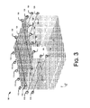
- Fig. 3 is a schematic perspective view of a system 100 to detect airborne impurities in a confined chamber 115, according to embodiments.
- the chamber 115 may comprise a confined compartment in a vehicle such as, e.g., a storage or passenger compartment in an aircraft or other vehicle.
- a plurality of channels 120 are formed in or mounted to surfaces of the chamber 115.
- a corresponding plurality of emitters 110 are positioned to direct radiation into the channels 120 and a corresponding plurality of receivers 130 are positioned to receive the radiation from the channels 120.
- the emitters 110 and receivers 130 may be coupled to one or more control modules 150.
- the emitters 110, channels 120, and receivers 130 form a system 100 capable of monitoring for airborne impurities in the compartment 115.
- the system 100 is capable of detecting impurities anywhere along the extents of the channels 120.
- a system 100 may be designed such that there is a 1:1 correspondence between emitters 110 and receivers 130.
- Fig. 4 is a schematic top view of a system to detect airborne impurities, according to embodiments in which there is a 1:1 correspondence between emitters 110 and receivers 130.
- Fig. 5 is a schematic top view of a system to detect airborne impurities, according to embodiments in which there is a 1:n correspondence between emitters 110 and receivers 130.
- radiation from an emitter 110 may be directed along a channel 120 which includes one or more beam splitter assemblies 160.
- Beam splitter assemblies 160 split the radiation incident on the beam splitter assembly 160 in to a first component which is directed to a first receiver 130, a second component which is directed to a second receiver 130, and a third component which is transmitted through the beam splitter assembly 160.
- Multiple beam splitter assemblies 160 may be positioned in series along the channel 120 to feed radiation to a plurality of receivers 130.
- Fig. 6 is a schematic illustration of a computing system 600 that may be used to monitor for airborne impurities.
- system 600 includes a computing device 608 and one or more accompanying input/output devices including a display 602 having a screen 604, one or more speakers 606, a keyboard 610, one or more other I/O device(s) 612, and a mouse 614.
- the other I/O device(s) 612 may include a touch screen, a voice-activated input device, a track ball, and any other device that allows the system 600 to receive input from a user.
- the computing device 608 includes system hardware 620 and memory 630, which may be implemented as random access memory and/or read-only memory.
- a file store 680 may be communicatively coupled to computing device 608.
- File store 680 may be internal to computing device 608 such as, e.g., one or more hard drives, CD-ROM drives, DVD-ROM drives, or other types of storage devices.
- File store 680 may also be external to computer 608 such as, e.g., one or more external hard drives, network attached storage, or a separate storage network.
- System hardware 620 may include one or more processors 622, video controllers 624, network interfaces 626, and bus structures 628.
- processor 622 may be embodied as an Intel ® Pentium IV® processor available from Intel Corporation, Santa Clara, California, USA.
- processor means any type of computational element, such as but not limited to, a microprocessor, a microcontroller, a complex instruction set computing (CISC) microprocessor, a reduced instruction set (RISC) microprocessor, a very long instruction word (VLIW) microprocessor, or any other type of processor or processing circuit.
- CISC complex instruction set computing
- RISC reduced instruction set
- VLIW very long instruction word
- Graphics controller 624 may function as an adjunction processor that manages graphics and/or video operations. Graphics controller 624 may be integrated onto the motherboard of computing system 600 or may be coupled via an expansion slot on the motherboard.
- network interface 626 could be a wired interface such as an Ethernet interface (see, e.g., Institute of Electrical and Electronics Engineers/IEEE 802.3-2002) or a wireless interface such as an IEEE 802.11a, b or g-compliant interface (see, e.g., IEEE Standard for IT-Telecommunications and information exchange between systems LAN/MAN--Part II: Wireless LAN Medium Access Control (MAC) and Physical Layer (PHY) specifications Amendment 4: Further Higher Data Rate Extension in the 2.4 GHz Band, 802.11G-2003).
- GPRS general packet radio service
- Bus structures 628 connect various components of system hardware 628.
- bus structures 628 may be one or more of several types of bus structure(s) including a memory bus, a peripheral bus or external bus, and/or a local bus using any variety of available bus architectures including, but not limited to, 11-bit bus, Industrial Standard Architecture (ISA), Micro-Channel Architecture (MSA), Extended ISA (EISA), Intelligent Drive Electronics (IDE), VESA Local Bus (VLB), Peripheral Component Interconnect (PCI), Universal Serial Bus (USB), Advanced Graphics Port (AGP), Personal Computer Memory Card International Association bus (PCMCIA), and Small Computer Systems Interface (SCSI).
- ISA Industrial Standard Architecture
- MSA Micro-Channel Architecture
- EISA Extended ISA
- IDE Intelligent Drive Electronics
- VLB VESA Local Bus
- PCI Peripheral Component Interconnect
- USB Universal Serial Bus
- AGP Advanced Graphics Port
- PCMCIA Personal Computer Memory Card International Association bus
- SCSI Small Computer Systems Interface
- Memory 630 may include an operating system 640 for managing operations of computing device 608.
- operating system 640 includes a hardware interface module 654 that provides an interface to system hardware 620.
- operating system 640 may include a file system 650 that manages files used in the operation of computing device 608 and a process control subsystem 652 that manages processes executing on computing device 608.
- memory module 630 may comprise an evaluation module 660 to implement the analysis operations described with reference to Fig. 2 .
- Operating system 640 may include (or manage) one or more communication interfaces that may operate in conjunction with system hardware 620 to transceive data packets and/or data streams from a remote source. Operating system 640 may further include a system call interface module 642 that provides an interface between the operating system 640 and one or more application modules resident in memory 630. Operating system 640 may be embodied as a UNIX operating system or any derivative thereof (e.g., Linux, Solaris, etc.) or as a Windows® brand operating system, or other operating systems.
- memory 630 includes a control module 140 to manage operations of the system 100.
- the control module 140 may include logic instructions encoded in a computer-readable storage medium which, when executed by processor 622, cause the processor 622 to activate, calibrate, and manage the system 100 to detect impurities in a confined chamber.
- Fig. 7 is a flowchart illustrating operations in a method detect airborne impurities, according to embodiments.
- a calibration procedure may be implemented.
- a calibration procedure may include activating the system when the atmosphere in the confined chamber is in normal operating conditions and free from evens such as, e.g., fire, which might generate airborne impurities in the chamber.
- Appropriate power levels may be established for the emitter(s) 110 and output signals from the receiver(s) 130 may be collected and stored (operation 715) in a suitable memory location, e.g., in the memory 630 or the file store 680 associated with the computing system 600.
- the system 100 may be activated for operation.
- the system 100 may be operated continuously or may be operated intermittently.
- the system 100 may be activated at periodic intervals and data may be collected during the intervals of activation.
- the emitters 110 are activated and radiation is emitted from the emitters 110.
- the receivers 130 receive the radiation and generate signals in response thereto.
- the output signal from the receiver(s) 130 is proportional to the radiation received.
- the airborne impurities will reduce the radiation levels that impinge upon the receivers(s) 130, and therefore the output signal of the receiver(s) 130.
- receiver data is collected and at operation 735 receiver data is compared with the data collected during the calibration process. If, at operation 740, the difference between the collected data and the calibration data does not exceed a threshold then control passes back to operation 725 and the system may continue normal operations monitoring for airborne impurities.
- the warning signal may be presented on a visual display, an auditory display, or combinations thereof.
- a system 100 may be incorporated into compartments of on an aircraft 800, such as an airplane, helicopter, spacecraft or the like.
- a system 100 may be incorporated into a ground-based vehicle such as a truck, tank, train, or the like, or on a water-based vehicle such as a ship.
- a system 100 may be incorporated into a land-based communication station.
- An aircraft comprising: a fuselage defining at least one confined chamber; a detection system to detect impurities in a confined chamber, comprising: an emitter to emit radiation; at least one channel positioned proximate the emitter to receive radiation from the emitter at a first end of the channel; and a receiver positioned proximate a second end of the channel to: receive radiation from the emitter; and generate a first signal in response to the radiation received from the emitter.
- control module comprising logic coupled to the receiver to: receive the first signal from the receiver; and generate a warning when the first signal indicates that an impurity in the chamber has exceeded a threshold.
- the chamber comprises a defined compartment in a vehicle; and the at least one channel extends along a surface of the compartment.
- A11 The aircraft of clause A10, further comprising: a plurality of channels extending along a surface of the compartment; a plurality of beam splitters to direct radiation from the emitter into the plurality of channels; and a plurality of receivers to: receive radiation from the emitter; and generate a first plurality of signals in response to the radiation received from the emitter.
- A12 The aircraft of clause A10, further comprising: a plurality of channels extending along a surface of the compartment; a plurality of emitters to emit radiation into the plurality of channels; and a plurality of receivers to: receive radiation from the emitters; and generate a first plurality of signals in response to the radiation received from the emitters.
Landscapes
- Physics & Mathematics (AREA)
- Analytical Chemistry (AREA)
- Chemical & Material Sciences (AREA)
- General Physics & Mathematics (AREA)
- Health & Medical Sciences (AREA)
- Emergency Management (AREA)
- Business, Economics & Management (AREA)
- Life Sciences & Earth Sciences (AREA)
- Biochemistry (AREA)
- General Health & Medical Sciences (AREA)
- Immunology (AREA)
- Pathology (AREA)
- Investigating Or Analysing Materials By Optical Means (AREA)
- Fire-Detection Mechanisms (AREA)
- Photometry And Measurement Of Optical Pulse Characteristics (AREA)
Abstract
Description
- The subject matter described herein relates to detection of airborne impurities and sensor systems for detection of airborne impurities in vehicles such as aircraft.
- Detectors may be used to detect the presence of airborne impurities. By way of example, smoke detectors may be used to detect the presence of smoke particles or aerosols in the air. Smoke detection in vehicle such as aircraft may be particularly challenging due to variations in configurations between aircraft cabin and turbulence in the cabin air created by air conditioning and air pressure management systems. Thus, systems and methods to detect airborne impurities in confined chambers such as, e.g., aircraft cabins may find utility.
- In one embodiment, a detection system to detect impurities in a confined chamber comprises an emitter to emit radiation, at least one channel positioned proximate the emitter to receive radiation from the emitter at a first end of the channel, and a receiver positioned proximate a second end of the channel to receive radiation from the emitter, and generate a first signal in response to the radiation received from the emitter
- In another embodiment, an aircraft comprises a fuselage defining at least one confined chamber, a detection system to detect impurities in a confined chamber, comprising an emitter to emit radiation, at least one channel positioned proximate the emitter to receive radiation from the emitter at a first end of the channel, and a receiver positioned proximate a second end of the channel to receive radiation from the emitter, and generate a first signal in response to the radiation received from the emitter.
- In another embodiment, a method to detect impurities in a confined chamber comprises emitting radiation from an emitter into a first end of at least at least one channel, receiving radiation from the emitter in a receiver at a second end of the at least one channel, and generating a first signal in response to the radiation received from the emitter.
- Further areas of applicability will become apparent from the description provided herein. It should be understood that the description and specific examples are intended for purposes of illustration only and are not intended to limit the scope of the present disclosure
- Embodiments of methods and systems in accordance with the teachings of the present disclosure are described in detail below with reference to the following drawings.
-
Fig. 1 is a schematic, high-level illustration of a system to detect airborne impurities, according to embodiments. -
Figs. 2A-2F are schematic side cross-sectional view of channels which may be used in a system to detect airborne impurities, according to embodiments. -
Fig. 3 is a schematic perspective view of a system to detect airborne impurities, according to embodiments. -
Fig. 4 is a schematic top view of a system to detect airborne impurities, according to embodiments. -
Fig. 5 is a schematic top view of a system to detect airborne impurities, according to embodiments. -
Fig. 6 is a schematic illustration of a computing device, according to embodiments. -
Fig. 7 is a flowchart illustrating operations in a method detect airborne impurities, according to embodiments. -
Fig. 8 is a schematic illustration of an aircraft, according to embodiments. - Configurations for systems and methods to detect airborne impurities such as, for example, smoke, in a confined chamber are described herein. Specific details of certain embodiments are set forth in the following description and the associated figures to provide a thorough understanding of such embodiments. One skilled in the art will understand, however, that alternate embodiments may be practiced without several of the details described in the following description.
- The invention may be described herein in terms of functional and/or logical block components and various processing steps. For the sake of brevity, conventional techniques related to data transmission, signaling, network control, and other functional aspects of the systems (and the individual operating components of the systems) may not be described in detail herein. Furthermore, the connecting lines shown in the various figures contained herein are intended to represent example functional relationships and/or physical couplings between the various elements. It should be noted that many alternative or additional functional relationships or physical connections may be present in a practical embodiment.
- The following description may refer to components or features being "connected" or "coupled" or "bonded" together. As used herein, unless expressly stated otherwise, "connected" means that one component/feature is in direct physically contact with another component/feature. Likewise, unless expressly stated otherwise, "coupled" or "bonded" means that one component/feature is directly or indirectly joined to (or directly or indirectly communicates with) another component/feature, and not necessarily directly physically connected. Thus, although the figures may depict example arrangements of elements, additional intervening elements, devices, features, or components may be present in an actual embodiment.
-
Fig. 1 is a schematic top-view of asystem 100 to detect impurities in a confined chamber. In the embodiment depicted inFig. 1 , thesystem 100 comprises one ormore emitter 110 to emit radiation, at least onechannel 120 positioned proximate the emitter(s) 110 to receive radiation from the emitter(s) 110 at afirst end 122 of thechannel 120, and one ormore receivers 130 positioned proximate asecond end 124 of thechannel 120. The receiver(s) 130 receive radiation from the emitter(s) 110 and generate a first signal in response to the radiation received from theemitter 110. Acontrol module 140 may be coupled to the emitter(s) 110 and the receiver(s) 130. - Emitter (s) 110 may be embodied as conventional radiation emitter(s) such as, for example, light emitting diodes (LEDs) or the like. In some embodiments emitter(s) 110 emit radiation in the visible spectrum, i.e., light. The radiation may be in a narrow frequency width such that the radiation is a single color to the naked eye. Emitter(s) 110 may comprise one or more collimators to collimate radiation emitted therefrom, and one or more lens assemblies to focus the radiation into a directional beam. In alternate embodiments the emitter(s) 110 may emit radiation outside the visible spectrum or may emit incoherent radiation, at least a portion of which may be visible as white light.
- Receiver(s) 130 may comprise a detector such as a photodiode or the like to detect radiation levels incident on an input of receiver(s) 130 and generate a signal representative of the level of radiation. By way of example, in some embodiments receiver(s) 130 generate an electrical signal having a voltage which is proportional to the level of radiation incident on receiver(s) 130.
- In the
system 100 depicted inFig. 1 the emitter(s) 110 and the receiver(s) 130 are coupled to one or more control module(s) 140, which includes control logic to manage operations of thesystem 100. In some embodiments control module(s) 140 may be embodied as, or may include, one or more processor-based controllers and may implement operations including initialization, calibration, power management, and data monitoring and collection. Various structural and functional aspect of control module(s) 140 are described in greater detail below. - In the embodiment depicted in
Fig. 1 the emitter(s) 110 are arranged such that radiation output from the emitter(s) 110 is directed into achannel 120 and the receiver(s) 130 are positioned to receive radiation from channel(s) 120. In the embodiment depicted inFig. 1 thechannel 120 has a length indicated by the reference L. The specific length L of thechannel 120 is not critical to the invention and may be a function of the dimensions of the confined chamber in which asystem 100 is installed. In general, the length L may vary from a few inches to tens or hundreds of feet. In general,channel 120 isolates airborne particles or aerosols from air turbulence in a confined chamber, which enables the system to obtain more accurate and stable readings of airborne particle concentration in the environment between the emitter(s) 110 and the receiver(s) 130. -
Figs. 2A-2F are schematic side cross-sectional view of channels which may be used in a system to detect airborne impurities, according to embodiments. Referring first toFig. 2A , in some embodiments thechannel 120 may be integrated into asurface 150 of a compartment. Alternately, as illustrated inFig. 2B , thechannel 120 may be mounted on asurface 150 of a compartment. Thechannel 120 may have a width indicated by reference w inFigs. 2A-2F that measures between 0.25 inches and 3.00 inches, and a depth that measures between 0.25 inches and 3.00 inches. One skilled in the art will recognize, however, that the particular dimensions of the channel are not critical, provided that the channel is dimensioned to reduce turbulent airflow in the volume defined by thechannel 120 and at the same time retain airborne impurities in thechannel 120. - Referring to
Figs. 2C - 2D , in some embodiments achannel 120 may comprise one ormore lips channel 120 to reduce turbulent airflow from the compartment into thechannel 120. Again, the specific dimensions of the lips are not critical, provided that the lip is dimensioned to reduce turbulent airflow in the volume defined by thechannel 120 and at the same time retain airborne impurities in thechannel 120. In some embodiments thelips - While the
channel 120 depicted inFigs. 2A-2D is substantially rectangular in cross-section, the specific configuration of the cross-sectional shape is not critical. Referring toFigs. 2E and 2F , in some embodiments thechannel 120 is substantially semicircular in cross-section. Other cross-sectional shapes may be implemented andchannels 120 of varying shapes may includelips Figs. 2C-2D . -
Fig. 3 is a schematic perspective view of asystem 100 to detect airborne impurities in a confinedchamber 115, according to embodiments. In some embodiments thechamber 115 may comprise a confined compartment in a vehicle such as, e.g., a storage or passenger compartment in an aircraft or other vehicle. In the embodiment depicted inFig. 3 a plurality ofchannels 120 are formed in or mounted to surfaces of thechamber 115. A corresponding plurality ofemitters 110 are positioned to direct radiation into thechannels 120 and a corresponding plurality ofreceivers 130 are positioned to receive the radiation from thechannels 120. As indicated inFig. 1 , theemitters 110 andreceivers 130 may be coupled to one ormore control modules 150. Theemitters 110,channels 120, andreceivers 130 form asystem 100 capable of monitoring for airborne impurities in thecompartment 115. Unlike conventional point-source monitoring systems which can only detect impurities at the point source, thesystem 100 is capable of detecting impurities anywhere along the extents of thechannels 120. - In some embodiments a
system 100 may be designed such that there is a 1:1 correspondence betweenemitters 110 andreceivers 130.Fig. 4 is a schematic top view of a system to detect airborne impurities, according to embodiments in which there is a 1:1 correspondence betweenemitters 110 andreceivers 130. - In alternate embodiments there may be a 1:n relationship between
emitters 110 andreceivers 130.Fig. 5 is a schematic top view of a system to detect airborne impurities, according to embodiments in which there is a 1:n correspondence betweenemitters 110 andreceivers 130. Referring toFig. 5 , in some embodiments radiation from anemitter 110 may be directed along achannel 120 which includes one or morebeam splitter assemblies 160.Beam splitter assemblies 160 split the radiation incident on thebeam splitter assembly 160 in to a first component which is directed to afirst receiver 130, a second component which is directed to asecond receiver 130, and a third component which is transmitted through thebeam splitter assembly 160. Multiplebeam splitter assemblies 160 may be positioned in series along thechannel 120 to feed radiation to a plurality ofreceivers 130. - As described above, the emitter(s) 110 and the receiver(s) 130 may be coupled to a
control module 140. In some embodiments thecontrol module 140 may be implemented as a logic module in a general purpose computing system. In a networked, computer-based system one or more of the computer systems include acontrol module 140 adapted to implement the control operations described with reference toFig. 6. Fig. 6 is a schematic illustration of acomputing system 600 that may be used to monitor for airborne impurities. In some embodiments,system 600 includes acomputing device 608 and one or more accompanying input/output devices including adisplay 602 having ascreen 604, one ormore speakers 606, akeyboard 610, one or more other I/O device(s) 612, and amouse 614. The other I/O device(s) 612 may include a touch screen, a voice-activated input device, a track ball, and any other device that allows thesystem 600 to receive input from a user. - The
computing device 608 includessystem hardware 620 andmemory 630, which may be implemented as random access memory and/or read-only memory. Afile store 680 may be communicatively coupled tocomputing device 608.File store 680 may be internal tocomputing device 608 such as, e.g., one or more hard drives, CD-ROM drives, DVD-ROM drives, or other types of storage devices.File store 680 may also be external tocomputer 608 such as, e.g., one or more external hard drives, network attached storage, or a separate storage network. -
System hardware 620 may include one ormore processors 622,video controllers 624, network interfaces 626, andbus structures 628. In one embodiment,processor 622 may be embodied as an Intel ® Pentium IV® processor available from Intel Corporation, Santa Clara, California, USA. As used herein, the term "processor" means any type of computational element, such as but not limited to, a microprocessor, a microcontroller, a complex instruction set computing (CISC) microprocessor, a reduced instruction set (RISC) microprocessor, a very long instruction word (VLIW) microprocessor, or any other type of processor or processing circuit. -
Graphics controller 624 may function as an adjunction processor that manages graphics and/or video operations.Graphics controller 624 may be integrated onto the motherboard ofcomputing system 600 or may be coupled via an expansion slot on the motherboard. - In one embodiment,
network interface 626 could be a wired interface such as an Ethernet interface (see, e.g., Institute of Electrical and Electronics Engineers/IEEE 802.3-2002) or a wireless interface such as an IEEE 802.11a, b or g-compliant interface (see, e.g., IEEE Standard for IT-Telecommunications and information exchange between systems LAN/MAN--Part II: Wireless LAN Medium Access Control (MAC) and Physical Layer (PHY) specifications Amendment 4: Further Higher Data Rate Extension in the 2.4 GHz Band, 802.11G-2003). Another example of a wireless interface would be a general packet radio service (GPRS) interface (see, e.g., Guidelines on GPRS Handset Requirements, Global System for Mobile Communications/GSM Association, Ver. 3.0.1, December 2002). -
Bus structures 628 connect various components ofsystem hardware 628. In one embodiment,bus structures 628 may be one or more of several types of bus structure(s) including a memory bus, a peripheral bus or external bus, and/or a local bus using any variety of available bus architectures including, but not limited to, 11-bit bus, Industrial Standard Architecture (ISA), Micro-Channel Architecture (MSA), Extended ISA (EISA), Intelligent Drive Electronics (IDE), VESA Local Bus (VLB), Peripheral Component Interconnect (PCI), Universal Serial Bus (USB), Advanced Graphics Port (AGP), Personal Computer Memory Card International Association bus (PCMCIA), and Small Computer Systems Interface (SCSI). -
Memory 630 may include anoperating system 640 for managing operations ofcomputing device 608. In one embodiment,operating system 640 includes a hardware interface module 654 that provides an interface tosystem hardware 620. In addition,operating system 640 may include a file system 650 that manages files used in the operation ofcomputing device 608 and a process control subsystem 652 that manages processes executing oncomputing device 608. Further,memory module 630 may comprise anevaluation module 660 to implement the analysis operations described with reference toFig. 2 . -
Operating system 640 may include (or manage) one or more communication interfaces that may operate in conjunction withsystem hardware 620 to transceive data packets and/or data streams from a remote source.Operating system 640 may further include a systemcall interface module 642 that provides an interface between theoperating system 640 and one or more application modules resident inmemory 630.Operating system 640 may be embodied as a UNIX operating system or any derivative thereof (e.g., Linux, Solaris, etc.) or as a Windows® brand operating system, or other operating systems. - In one embodiment,
memory 630 includes acontrol module 140 to manage operations of thesystem 100. Thecontrol module 140 may include logic instructions encoded in a computer-readable storage medium which, when executed byprocessor 622, cause theprocessor 622 to activate, calibrate, and manage thesystem 100 to detect impurities in a confined chamber. -
Fig. 7 is a flowchart illustrating operations in a method detect airborne impurities, according to embodiments. Referring toFig. 7 , at operation 710 a calibration procedure may be implemented. In some embodiments a calibration procedure may include activating the system when the atmosphere in the confined chamber is in normal operating conditions and free from evens such as, e.g., fire, which might generate airborne impurities in the chamber. Appropriate power levels may be established for the emitter(s) 110 and output signals from the receiver(s) 130 may be collected and stored (operation 715) in a suitable memory location, e.g., in thememory 630 or thefile store 680 associated with thecomputing system 600. - Once the
system 100 is calibrated it may be activated for operation. In use, thesystem 100 may be operated continuously or may be operated intermittently. For example, thesystem 100 may be activated at periodic intervals and data may be collected during the intervals of activation. Whatever mode of operation is selected, atoperation 720 theemitters 110 are activated and radiation is emitted from theemitters 110. Atoperation 725 thereceivers 130 receive the radiation and generate signals in response thereto. In some embodiments the output signal from the receiver(s) 130 is proportional to the radiation received. Thus, when the air in the confined chamber is substantially free of airborne impurities such as smoke the signal generated by the receiver(s) 130 should approximate the signal generated during the calibration process. By contrast, in the event a fire or other event disburses airborne impurities in the air of the confinedchamber 115, the airborne impurities will reduce the radiation levels that impinge upon the receivers(s) 130, and therefore the output signal of the receiver(s) 130. - At
operation 730 receiver data is collected and atoperation 735 receiver data is compared with the data collected during the calibration process. If, atoperation 740, the difference between the collected data and the calibration data does not exceed a threshold then control passes back tooperation 725 and the system may continue normal operations monitoring for airborne impurities. - By contrast, if at
operation 740 the difference exceeds a threshold then control passes tooperation 745 and a warning signal is generated, which signal may be presented on a user interface atoperation 750. By way of example, the warning signal may be presented on a visual display, an auditory display, or combinations thereof. - In some embodiments a
system 100 may be incorporated into compartments of on anaircraft 800, such as an airplane, helicopter, spacecraft or the like. In alternate embodiments asystem 100 may be incorporated into a ground-based vehicle such as a truck, tank, train, or the like, or on a water-based vehicle such as a ship. In further embodiments asystem 100 may be incorporated into a land-based communication station. - While various embodiments have been described, those skilled in the art will recognize modifications or variations which might be made without departing from the present disclosure. The examples illustrate the various embodiments and are not intended to limit the present disclosure. Therefore, the description and claims should be interpreted liberally with only such limitation as is necessary in view of the pertinent prior art.
- A8. An aircraft comprising: a fuselage defining at least one confined chamber; a detection system to detect impurities in a confined chamber, comprising: an emitter to emit radiation; at least one channel positioned proximate the emitter to receive radiation from the emitter at a first end of the channel; and a receiver positioned proximate a second end of the channel to: receive radiation from the emitter; and generate a first signal in response to the radiation received from the emitter.
- A9. The aircraft of clause A8, further comprising a control module comprising logic coupled to the receiver to: receive the first signal from the receiver; and generate a warning when the first signal indicates that an impurity in the chamber has exceeded a threshold.
- A10. The aircraft of clause A8, wherein: the chamber comprises a defined compartment in a vehicle; and the at least one channel extends along a surface of the compartment.
- A11. The aircraft of clause A10, further comprising: a plurality of channels extending along a surface of the compartment; a plurality of beam splitters to direct radiation from the emitter into the plurality of channels; and a plurality of receivers to: receive radiation from the emitter; and generate a first plurality of signals in response to the radiation received from the emitter.
- A12. The aircraft of clause A10, further comprising: a plurality of channels extending along a surface of the compartment; a plurality of emitters to emit radiation into the plurality of channels; and a plurality of receivers to: receive radiation from the emitters; and generate a first plurality of signals in response to the radiation received from the emitters.
- A13. The aircraft of clause A10, wherein the at least one channel is integrated into a surface of the compartment.
- A14. The aircraft of the clause A10, wherein the at least one channel is mounted onto a surface of the compartment.
Claims (12)
- A system(100) to detect impurities in a confined chamber, comprising:an emitter (110)to emit radiation;at least one channel (120)positioned proximate the emitter to receive radiation from the emitter at a first end (122)of the channel(120); anda receiver (130)positioned proximate a second end(124) of the channel to:receive radiation from the emitter; andgenerate a first signal in response to the radiation received from the emitter(110).
- The system of claim 1, further comprising a control module (140) comprising logic coupled to the receiver (130) to:receive the first signal from the receiver(130); andgenerate a warning when the first signal indicates that an impurity in the chamber (115)has exceeded a threshold.
- The system of claim 1, wherein:the chamber comprises a defined compartment in a vehicle; andthe at least one channel extends along a surface of the compartment.
- The detection system of claim 3, further comprising:a plurality of channels extending along a surface (150) of the compartment (115);a plurality of beam splitters to direct radiation from the emitter into the plurality of channels; anda plurality of receivers to:receive radiation from the emitter; andgenerate a first plurality of signals in response to the radiation received from the emitter.
- The system of claim 3, further comprising:a plurality of channels(120) extending along a surface of the compartment(115);a plurality of emitters to emit radiation into the plurality of channels; anda plurality of receivers to:receive radiation from the emitter(110); andgenerate a first plurality of signals in response to the radiation received from the emitter.
- The system of claim 3, wherein the at least one channel is integrated into a surface of the compartment.
- The system of claim 3, wherein the at least one channel is mounted onto a surface of the compartment.
- A method to detect impurities in a confined chamber(115), comprising:emitting radiation from an emitter (110)into a first end of at least one channel;
andreceiving radiation from the emitter in a receiver (130) at a second end of the at least one channel; andgenerating a first signal in response to the radiation received from the emitter. - The method of claim 8, further comprising:receiving, in a control module coupled to the receiver, the first signal from the receiver; andgenerating a warning when the first signal indicates that an impurity in the chamber has exceeded a threshold.
- The method of claim 8, wherein:the chamber comprises a defined compartment in a vehicle; andthe at least one channel extends along a surface of the compartment.
- The method of claim 10, further comprising:a plurality of channels (120) extending along a surface of the compartment;a plurality of beam splitters (160)to direct radiation from the emitter into the plurality of channels; anda plurality of receivers (130)to:receive radiation from the emitter; andgenerate a first plurality of signals in response to the radiation received from the emitter.
- The method of claim 10, further comprising:a plurality of channels extending along a surface of the compartment;a plurality of emitters to emit radiation into the plurality of channels; anda plurality of receivers to:receive radiation from the emitters; andgenerate a first plurality of signals in response to the radiation received from the emitters.
Applications Claiming Priority (1)
| Application Number | Priority Date | Filing Date | Title |
|---|---|---|---|
| US13/275,575 US8899097B2 (en) | 2011-10-18 | 2011-10-18 | Airborne impurities detection |
Publications (2)
| Publication Number | Publication Date |
|---|---|
| EP2584341A1 true EP2584341A1 (en) | 2013-04-24 |
| EP2584341B1 EP2584341B1 (en) | 2022-12-07 |
Family
ID=47221133
Family Applications (1)
| Application Number | Title | Priority Date | Filing Date |
|---|---|---|---|
| EP12188126.2A Active EP2584341B1 (en) | 2011-10-18 | 2012-10-11 | Airborne impurities detection |
Country Status (4)
| Country | Link |
|---|---|
| US (1) | US8899097B2 (en) |
| EP (1) | EP2584341B1 (en) |
| JP (1) | JP6111039B2 (en) |
| CN (1) | CN103115871A (en) |
Cited By (1)
| Publication number | Priority date | Publication date | Assignee | Title |
|---|---|---|---|---|
| DE102018125494A1 (en) * | 2018-10-15 | 2020-04-16 | Bombardier Transportation Gmbh | Smoke detector for detecting smoke in sections, and vehicle having a smoke detector |
Families Citing this family (6)
| Publication number | Priority date | Publication date | Assignee | Title |
|---|---|---|---|---|
| CN105628617A (en) * | 2014-10-28 | 2016-06-01 | 中国航空工业集团公司西安飞机设计研究所 | Airplane smoke detection system suitable for enclosed space |
| US10078948B2 (en) * | 2016-01-26 | 2018-09-18 | Honeywell International Inc. | Smoke detector with a double optical chamber |
| WO2018170257A1 (en) * | 2017-03-16 | 2018-09-20 | Symmetry Sensors, Inc. | System and method for particle characterization |
| US10295457B1 (en) | 2017-06-13 | 2019-05-21 | Larry Ocheltree | Airplane cabin air quality monitoring system |
| US11465755B1 (en) | 2018-04-30 | 2022-10-11 | United States Of America As Represented By The Secretary Of The Air Force | Aircraft air quality testing system |
| US11493229B2 (en) | 2019-03-20 | 2022-11-08 | Carrier Corporation | Chamberless wide area duct smoke detector |
Citations (5)
| Publication number | Priority date | Publication date | Assignee | Title |
|---|---|---|---|---|
| US3524707A (en) * | 1967-08-14 | 1970-08-18 | Julian E Hansen Sr | Pulsating light source smoke detector |
| GB1390227A (en) * | 1971-06-18 | 1975-04-09 | Sick Erwin | Method of and apparatus for determining the concentration of gases by optical extinction measurement |
| US5791982A (en) * | 1997-04-16 | 1998-08-11 | Alliedsignal Inc. | System for improving the well-being of humans in a commercial aircraft |
| WO1999054700A2 (en) * | 1998-04-20 | 1999-10-28 | Horace Rekunyk | Infrared remote monitoring system for leak |
| US20050253730A1 (en) * | 2004-05-13 | 2005-11-17 | Job Lizenz Gmbh & Co. Kg | Method for the detection and signaling of dew films in smoke detectors |
Family Cites Families (24)
| Publication number | Priority date | Publication date | Assignee | Title |
|---|---|---|---|---|
| US2604597A (en) * | 1949-02-03 | 1952-07-22 | C O Two Fire Equipment Co | Smoke detector |
| US2627064A (en) * | 1950-07-15 | 1953-01-27 | C O Two Fire Equipment Co | Smoke detector testing means |
| JPS5830637B2 (en) * | 1976-04-15 | 1983-06-30 | 松下電工株式会社 | distributed smoke detector |
| US4185278A (en) * | 1977-09-22 | 1980-01-22 | HF Systems, Incorporated | Obscuration type smoke detector |
| JPS5476784U (en) * | 1977-11-10 | 1979-05-31 | ||
| JPS59147242A (en) * | 1983-02-10 | 1984-08-23 | Nippon Denso Co Ltd | Dust detecting apparatus for automobile |
| JPS6044192U (en) * | 1983-08-31 | 1985-03-28 | 富士通株式会社 | Smoke detectors |
| JPS60100034A (en) * | 1983-11-05 | 1985-06-03 | Showa Denko Kk | Method and apparatus for measuring concentration of ethylene gas |
| JPS6146454U (en) * | 1984-08-30 | 1986-03-28 | 能美防災株式会社 | photoelectric smoke detector |
| GB8711309D0 (en) * | 1987-05-13 | 1987-06-17 | Combustion Dev Ltd | Monitoring equipment |
| US4870394A (en) * | 1988-01-29 | 1989-09-26 | Systron-Donner Corp. | Smoke detector with improved testing |
| US5486810A (en) * | 1993-02-04 | 1996-01-23 | Schwarz; Frank | Infrared detector for detecting motion and fire and an alarm system including the same |
| DE4343897A1 (en) * | 1993-12-22 | 1995-06-29 | Bosch Gmbh Robert | Device for determining the density and concentration of visible components in fluids |
| US6111511A (en) * | 1998-01-20 | 2000-08-29 | Purdue Research Foundations | Flame and smoke detector |
| US6377183B1 (en) | 1999-06-17 | 2002-04-23 | The Boeing Company | Smoke detector having a moisture compensating device |
| JP3605367B2 (en) * | 2001-03-01 | 2004-12-22 | 三菱重工業株式会社 | Laser measurement method and laser measurement system |
| US6975237B2 (en) | 2003-01-10 | 2005-12-13 | The Boeing Company | System, controller and method of detecting a hazardous condition within an enclosure having a ventilation system |
| US7154388B2 (en) | 2003-11-13 | 2006-12-26 | The Boeing Company | Vehicle compartment smoke and fire indication system and method for use |
| US7262844B2 (en) * | 2005-01-13 | 2007-08-28 | The Curators Of The University Of Missouri | Ultrasensitive spectrophotometer |
| JPWO2007096964A1 (en) * | 2006-02-23 | 2009-07-09 | ホーチキ株式会社 | Remote sensor |
| US7849931B2 (en) | 2006-09-07 | 2010-12-14 | The Boeing Company | Integrated environmental control system for a cargo stowage compartment on a mobile platform |
| US7688199B2 (en) | 2006-11-02 | 2010-03-30 | The Boeing Company | Smoke and fire detection in aircraft cargo compartments |
| JP2009030982A (en) * | 2007-07-24 | 2009-02-12 | Kyocera Corp | Fine powder sensor device |
| US8022793B2 (en) * | 2008-11-25 | 2011-09-20 | The Boeing Company | Sandwich vehicle structure having integrated electromagnetic radiation pathways |
-
2011
- 2011-10-18 US US13/275,575 patent/US8899097B2/en active Active
-
2012
- 2012-10-11 EP EP12188126.2A patent/EP2584341B1/en active Active
- 2012-10-17 JP JP2012229559A patent/JP6111039B2/en active Active
- 2012-10-18 CN CN2012103967648A patent/CN103115871A/en active Pending
Patent Citations (5)
| Publication number | Priority date | Publication date | Assignee | Title |
|---|---|---|---|---|
| US3524707A (en) * | 1967-08-14 | 1970-08-18 | Julian E Hansen Sr | Pulsating light source smoke detector |
| GB1390227A (en) * | 1971-06-18 | 1975-04-09 | Sick Erwin | Method of and apparatus for determining the concentration of gases by optical extinction measurement |
| US5791982A (en) * | 1997-04-16 | 1998-08-11 | Alliedsignal Inc. | System for improving the well-being of humans in a commercial aircraft |
| WO1999054700A2 (en) * | 1998-04-20 | 1999-10-28 | Horace Rekunyk | Infrared remote monitoring system for leak |
| US20050253730A1 (en) * | 2004-05-13 | 2005-11-17 | Job Lizenz Gmbh & Co. Kg | Method for the detection and signaling of dew films in smoke detectors |
Non-Patent Citations (1)
| Title |
|---|
| "Guidelines on GPRS Handset Requirements", December 2002, GLOBAL SYSTEM FOR MOBILE COMMUNICATIONS/GSM ASSOCIATION |
Cited By (1)
| Publication number | Priority date | Publication date | Assignee | Title |
|---|---|---|---|---|
| DE102018125494A1 (en) * | 2018-10-15 | 2020-04-16 | Bombardier Transportation Gmbh | Smoke detector for detecting smoke in sections, and vehicle having a smoke detector |
Also Published As
| Publication number | Publication date |
|---|---|
| CN103115871A (en) | 2013-05-22 |
| US8899097B2 (en) | 2014-12-02 |
| JP2013088434A (en) | 2013-05-13 |
| US20130091928A1 (en) | 2013-04-18 |
| EP2584341B1 (en) | 2022-12-07 |
| JP6111039B2 (en) | 2017-04-05 |
Similar Documents
| Publication | Publication Date | Title |
|---|---|---|
| US8899097B2 (en) | Airborne impurities detection | |
| EP2824460B1 (en) | System and method for detecting turbulence based upon observations of light scintillation | |
| US10063794B2 (en) | System and method for detecting adverse atmospheric conditions ahead of an aircraft | |
| US10392125B2 (en) | System and method for onboard wake and clear air turbulence avoidance | |
| US8958942B2 (en) | Systems and methods for displaying aircraft braking distance during surface operations | |
| US8392045B2 (en) | System and methods for aircraft preflight inspection | |
| US9079670B2 (en) | Aerosol detection | |
| JP6282400B2 (en) | Supercooled large droplet icing condition detection system using laser | |
| EP2864202B1 (en) | Helicopter collision-avoidance system using light fixture mounted radar sensors | |
| EP2431957B1 (en) | Systems and methods for early detection of aircraft approach to volcanic plume | |
| CA2854288C (en) | Large droplet detection by statistical fluctuations in lidar backscatter | |
| CN103473957A (en) | Airport surface collision-avoidance system (ASCAS) | |
| EP2187372B1 (en) | Aircraft collision avoidance system | |
| De Sousa et al. | Aerial forest fire detection and monitoring using a small UAV | |
| US9532013B1 (en) | Sensor-based image(s) integrity determination system, device, and method | |
| US20160364866A1 (en) | Locating light sources using aircraft | |
| CN105044707B (en) | Based on wireless ultraviolet light helicopter ranging and collision-proof method | |
| EP2151384A3 (en) | Systems and methods for improving pilot situational awareness during landing | |
| US10991261B1 (en) | Glideslope visibility monitor | |
| Norris et al. | Performance comparison of visual, infrared, and ultraviolet sensors for landing aircraft in fog | |
| Caso et al. | Impact of Temperature and Humidity on a 3D LiDAR Sensor: Performance and Characterization | |
| Xiao et al. | Design and Implementation of a Low-Altitude Situational Awareness System for Helicopters Based on Radar Detection Technology | |
| CN117805856A (en) | Throwing visibility vertical profile observation device and observation method | |
| CN205449743U (en) | Haze detector system | |
| WO2013091902A1 (en) | System and method for detecting adverse atmospheric conditions ahead of an aircraft |
Legal Events
| Date | Code | Title | Description |
|---|---|---|---|
| PUAI | Public reference made under article 153(3) epc to a published international application that has entered the european phase |
Free format text: ORIGINAL CODE: 0009012 |
|
| 17P | Request for examination filed |
Effective date: 20121011 |
|
| AK | Designated contracting states |
Kind code of ref document: A1 Designated state(s): AL AT BE BG CH CY CZ DE DK EE ES FI FR GB GR HR HU IE IS IT LI LT LU LV MC MK MT NL NO PL PT RO RS SE SI SK SM TR |
|
| AX | Request for extension of the european patent |
Extension state: BA ME |
|
| STAA | Information on the status of an ep patent application or granted ep patent |
Free format text: STATUS: EXAMINATION IS IN PROGRESS |
|
| 17Q | First examination report despatched |
Effective date: 20190415 |
|
| GRAP | Despatch of communication of intention to grant a patent |
Free format text: ORIGINAL CODE: EPIDOSNIGR1 |
|
| STAA | Information on the status of an ep patent application or granted ep patent |
Free format text: STATUS: GRANT OF PATENT IS INTENDED |
|
| RIC1 | Information provided on ipc code assigned before grant |
Ipc: G08B 29/20 20060101ALI20220513BHEP Ipc: G08B 17/113 20060101ALI20220513BHEP Ipc: G01N 21/27 20060101ALI20220513BHEP Ipc: G01N 1/22 20060101ALI20220513BHEP Ipc: G08B 17/103 20060101ALI20220513BHEP Ipc: G08B 17/107 20060101ALI20220513BHEP Ipc: G01N 21/53 20060101AFI20220513BHEP |
|
| INTG | Intention to grant announced |
Effective date: 20220602 |
|
| GRAS | Grant fee paid |
Free format text: ORIGINAL CODE: EPIDOSNIGR3 |
|
| GRAA | (expected) grant |
Free format text: ORIGINAL CODE: 0009210 |
|
| STAA | Information on the status of an ep patent application or granted ep patent |
Free format text: STATUS: THE PATENT HAS BEEN GRANTED |
|
| AK | Designated contracting states |
Kind code of ref document: B1 Designated state(s): AL AT BE BG CH CY CZ DE DK EE ES FI FR GB GR HR HU IE IS IT LI LT LU LV MC MK MT NL NO PL PT RO RS SE SI SK SM TR |
|
| REG | Reference to a national code |
Ref country code: GB Ref legal event code: FG4D |
|
| REG | Reference to a national code |
Ref country code: CH Ref legal event code: EP Ref country code: AT Ref legal event code: REF Ref document number: 1536583 Country of ref document: AT Kind code of ref document: T Effective date: 20221215 |
|
| REG | Reference to a national code |
Ref country code: DE Ref legal event code: R096 Ref document number: 602012079082 Country of ref document: DE |
|
| REG | Reference to a national code |
Ref country code: IE Ref legal event code: FG4D |
|
| RAP4 | Party data changed (patent owner data changed or rights of a patent transferred) |
Owner name: THE BOEING COMPANY |
|
| REG | Reference to a national code |
Ref country code: LT Ref legal event code: MG9D |
|
| REG | Reference to a national code |
Ref country code: NL Ref legal event code: MP Effective date: 20221207 |
|
| PG25 | Lapsed in a contracting state [announced via postgrant information from national office to epo] |
Ref country code: SE Free format text: LAPSE BECAUSE OF FAILURE TO SUBMIT A TRANSLATION OF THE DESCRIPTION OR TO PAY THE FEE WITHIN THE PRESCRIBED TIME-LIMIT Effective date: 20221207 Ref country code: NO Free format text: LAPSE BECAUSE OF FAILURE TO SUBMIT A TRANSLATION OF THE DESCRIPTION OR TO PAY THE FEE WITHIN THE PRESCRIBED TIME-LIMIT Effective date: 20230307 Ref country code: LT Free format text: LAPSE BECAUSE OF FAILURE TO SUBMIT A TRANSLATION OF THE DESCRIPTION OR TO PAY THE FEE WITHIN THE PRESCRIBED TIME-LIMIT Effective date: 20221207 Ref country code: FI Free format text: LAPSE BECAUSE OF FAILURE TO SUBMIT A TRANSLATION OF THE DESCRIPTION OR TO PAY THE FEE WITHIN THE PRESCRIBED TIME-LIMIT Effective date: 20221207 Ref country code: ES Free format text: LAPSE BECAUSE OF FAILURE TO SUBMIT A TRANSLATION OF THE DESCRIPTION OR TO PAY THE FEE WITHIN THE PRESCRIBED TIME-LIMIT Effective date: 20221207 |
|
| REG | Reference to a national code |
Ref country code: AT Ref legal event code: MK05 Ref document number: 1536583 Country of ref document: AT Kind code of ref document: T Effective date: 20221207 |
|
| PG25 | Lapsed in a contracting state [announced via postgrant information from national office to epo] |
Ref country code: RS Free format text: LAPSE BECAUSE OF FAILURE TO SUBMIT A TRANSLATION OF THE DESCRIPTION OR TO PAY THE FEE WITHIN THE PRESCRIBED TIME-LIMIT Effective date: 20221207 Ref country code: PL Free format text: LAPSE BECAUSE OF FAILURE TO SUBMIT A TRANSLATION OF THE DESCRIPTION OR TO PAY THE FEE WITHIN THE PRESCRIBED TIME-LIMIT Effective date: 20221207 Ref country code: LV Free format text: LAPSE BECAUSE OF FAILURE TO SUBMIT A TRANSLATION OF THE DESCRIPTION OR TO PAY THE FEE WITHIN THE PRESCRIBED TIME-LIMIT Effective date: 20221207 Ref country code: HR Free format text: LAPSE BECAUSE OF FAILURE TO SUBMIT A TRANSLATION OF THE DESCRIPTION OR TO PAY THE FEE WITHIN THE PRESCRIBED TIME-LIMIT Effective date: 20221207 Ref country code: GR Free format text: LAPSE BECAUSE OF FAILURE TO SUBMIT A TRANSLATION OF THE DESCRIPTION OR TO PAY THE FEE WITHIN THE PRESCRIBED TIME-LIMIT Effective date: 20230308 |
|
| P01 | Opt-out of the competence of the unified patent court (upc) registered |
Effective date: 20230516 |
|
| PG25 | Lapsed in a contracting state [announced via postgrant information from national office to epo] |
Ref country code: NL Free format text: LAPSE BECAUSE OF FAILURE TO SUBMIT A TRANSLATION OF THE DESCRIPTION OR TO PAY THE FEE WITHIN THE PRESCRIBED TIME-LIMIT Effective date: 20221207 |
|
| PG25 | Lapsed in a contracting state [announced via postgrant information from national office to epo] |
Ref country code: SM Free format text: LAPSE BECAUSE OF FAILURE TO SUBMIT A TRANSLATION OF THE DESCRIPTION OR TO PAY THE FEE WITHIN THE PRESCRIBED TIME-LIMIT Effective date: 20221207 Ref country code: RO Free format text: LAPSE BECAUSE OF FAILURE TO SUBMIT A TRANSLATION OF THE DESCRIPTION OR TO PAY THE FEE WITHIN THE PRESCRIBED TIME-LIMIT Effective date: 20221207 Ref country code: PT Free format text: LAPSE BECAUSE OF FAILURE TO SUBMIT A TRANSLATION OF THE DESCRIPTION OR TO PAY THE FEE WITHIN THE PRESCRIBED TIME-LIMIT Effective date: 20230410 Ref country code: EE Free format text: LAPSE BECAUSE OF FAILURE TO SUBMIT A TRANSLATION OF THE DESCRIPTION OR TO PAY THE FEE WITHIN THE PRESCRIBED TIME-LIMIT Effective date: 20221207 Ref country code: CZ Free format text: LAPSE BECAUSE OF FAILURE TO SUBMIT A TRANSLATION OF THE DESCRIPTION OR TO PAY THE FEE WITHIN THE PRESCRIBED TIME-LIMIT Effective date: 20221207 Ref country code: AT Free format text: LAPSE BECAUSE OF FAILURE TO SUBMIT A TRANSLATION OF THE DESCRIPTION OR TO PAY THE FEE WITHIN THE PRESCRIBED TIME-LIMIT Effective date: 20221207 |
|
| PG25 | Lapsed in a contracting state [announced via postgrant information from national office to epo] |
Ref country code: SK Free format text: LAPSE BECAUSE OF FAILURE TO SUBMIT A TRANSLATION OF THE DESCRIPTION OR TO PAY THE FEE WITHIN THE PRESCRIBED TIME-LIMIT Effective date: 20221207 Ref country code: IS Free format text: LAPSE BECAUSE OF FAILURE TO SUBMIT A TRANSLATION OF THE DESCRIPTION OR TO PAY THE FEE WITHIN THE PRESCRIBED TIME-LIMIT Effective date: 20230407 Ref country code: AL Free format text: LAPSE BECAUSE OF FAILURE TO SUBMIT A TRANSLATION OF THE DESCRIPTION OR TO PAY THE FEE WITHIN THE PRESCRIBED TIME-LIMIT Effective date: 20221207 |
|
| REG | Reference to a national code |
Ref country code: DE Ref legal event code: R097 Ref document number: 602012079082 Country of ref document: DE |
|
| PLBE | No opposition filed within time limit |
Free format text: ORIGINAL CODE: 0009261 |
|
| STAA | Information on the status of an ep patent application or granted ep patent |
Free format text: STATUS: NO OPPOSITION FILED WITHIN TIME LIMIT |
|
| PG25 | Lapsed in a contracting state [announced via postgrant information from national office to epo] |
Ref country code: DK Free format text: LAPSE BECAUSE OF FAILURE TO SUBMIT A TRANSLATION OF THE DESCRIPTION OR TO PAY THE FEE WITHIN THE PRESCRIBED TIME-LIMIT Effective date: 20221207 |
|
| 26N | No opposition filed |
Effective date: 20230908 |
|
| PG25 | Lapsed in a contracting state [announced via postgrant information from national office to epo] |
Ref country code: SI Free format text: LAPSE BECAUSE OF FAILURE TO SUBMIT A TRANSLATION OF THE DESCRIPTION OR TO PAY THE FEE WITHIN THE PRESCRIBED TIME-LIMIT Effective date: 20221207 |
|
| PG25 | Lapsed in a contracting state [announced via postgrant information from national office to epo] |
Ref country code: IT Free format text: LAPSE BECAUSE OF FAILURE TO SUBMIT A TRANSLATION OF THE DESCRIPTION OR TO PAY THE FEE WITHIN THE PRESCRIBED TIME-LIMIT Effective date: 20221207 Ref country code: MC Free format text: LAPSE BECAUSE OF FAILURE TO SUBMIT A TRANSLATION OF THE DESCRIPTION OR TO PAY THE FEE WITHIN THE PRESCRIBED TIME-LIMIT Effective date: 20221207 |
|
| REG | Reference to a national code |
Ref country code: CH Ref legal event code: PL |
|
| REG | Reference to a national code |
Ref country code: BE Ref legal event code: MM Effective date: 20231031 |
|
| PG25 | Lapsed in a contracting state [announced via postgrant information from national office to epo] |
Ref country code: LU Free format text: LAPSE BECAUSE OF NON-PAYMENT OF DUE FEES Effective date: 20231011 |
|
| PG25 | Lapsed in a contracting state [announced via postgrant information from national office to epo] |
Ref country code: LU Free format text: LAPSE BECAUSE OF NON-PAYMENT OF DUE FEES Effective date: 20231011 |
|
| PG25 | Lapsed in a contracting state [announced via postgrant information from national office to epo] |
Ref country code: CH Free format text: LAPSE BECAUSE OF NON-PAYMENT OF DUE FEES Effective date: 20231031 |
|
| PG25 | Lapsed in a contracting state [announced via postgrant information from national office to epo] |
Ref country code: CH Free format text: LAPSE BECAUSE OF NON-PAYMENT OF DUE FEES Effective date: 20231031 |
|
| PG25 | Lapsed in a contracting state [announced via postgrant information from national office to epo] |
Ref country code: BE Free format text: LAPSE BECAUSE OF NON-PAYMENT OF DUE FEES Effective date: 20231031 |
|
| PG25 | Lapsed in a contracting state [announced via postgrant information from national office to epo] |
Ref country code: IE Free format text: LAPSE BECAUSE OF NON-PAYMENT OF DUE FEES Effective date: 20231011 |
|
| PG25 | Lapsed in a contracting state [announced via postgrant information from national office to epo] |
Ref country code: IE Free format text: LAPSE BECAUSE OF NON-PAYMENT OF DUE FEES Effective date: 20231011 |
|
| PG25 | Lapsed in a contracting state [announced via postgrant information from national office to epo] |
Ref country code: BG Free format text: LAPSE BECAUSE OF FAILURE TO SUBMIT A TRANSLATION OF THE DESCRIPTION OR TO PAY THE FEE WITHIN THE PRESCRIBED TIME-LIMIT Effective date: 20221207 |
|
| PG25 | Lapsed in a contracting state [announced via postgrant information from national office to epo] |
Ref country code: BG Free format text: LAPSE BECAUSE OF FAILURE TO SUBMIT A TRANSLATION OF THE DESCRIPTION OR TO PAY THE FEE WITHIN THE PRESCRIBED TIME-LIMIT Effective date: 20221207 |
|
| PG25 | Lapsed in a contracting state [announced via postgrant information from national office to epo] |
Ref country code: CY Free format text: LAPSE BECAUSE OF FAILURE TO SUBMIT A TRANSLATION OF THE DESCRIPTION OR TO PAY THE FEE WITHIN THE PRESCRIBED TIME-LIMIT; INVALID AB INITIO Effective date: 20121011 |
|
| PG25 | Lapsed in a contracting state [announced via postgrant information from national office to epo] |
Ref country code: HU Free format text: LAPSE BECAUSE OF FAILURE TO SUBMIT A TRANSLATION OF THE DESCRIPTION OR TO PAY THE FEE WITHIN THE PRESCRIBED TIME-LIMIT; INVALID AB INITIO Effective date: 20121011 |
|
| PG25 | Lapsed in a contracting state [announced via postgrant information from national office to epo] |
Ref country code: TR Free format text: LAPSE BECAUSE OF FAILURE TO SUBMIT A TRANSLATION OF THE DESCRIPTION OR TO PAY THE FEE WITHIN THE PRESCRIBED TIME-LIMIT Effective date: 20221207 |
|
| PGFP | Annual fee paid to national office [announced via postgrant information from national office to epo] |
Ref country code: DE Payment date: 20251029 Year of fee payment: 14 |
|
| PGFP | Annual fee paid to national office [announced via postgrant information from national office to epo] |
Ref country code: GB Payment date: 20251027 Year of fee payment: 14 |
|
| PGFP | Annual fee paid to national office [announced via postgrant information from national office to epo] |
Ref country code: FR Payment date: 20251027 Year of fee payment: 14 |