EP2584233A2 - Pressure regulating float valve - Google Patents
Pressure regulating float valve Download PDFInfo
- Publication number
- EP2584233A2 EP2584233A2 EP20120188262 EP12188262A EP2584233A2 EP 2584233 A2 EP2584233 A2 EP 2584233A2 EP 20120188262 EP20120188262 EP 20120188262 EP 12188262 A EP12188262 A EP 12188262A EP 2584233 A2 EP2584233 A2 EP 2584233A2
- Authority
- EP
- European Patent Office
- Prior art keywords
- conduit
- fuel tank
- fuel
- aircraft
- seal plate
- Prior art date
- Legal status (The legal status is an assumption and is not a legal conclusion. Google has not performed a legal analysis and makes no representation as to the accuracy of the status listed.)
- Granted
Links
Images


Classifications
-
- B—PERFORMING OPERATIONS; TRANSPORTING
- B64—AIRCRAFT; AVIATION; COSMONAUTICS
- B64D—EQUIPMENT FOR FITTING IN OR TO AIRCRAFT; FLIGHT SUITS; PARACHUTES; ARRANGEMENT OR MOUNTING OF POWER PLANTS OR PROPULSION TRANSMISSIONS IN AIRCRAFT
- B64D37/00—Arrangements in connection with fuel supply for power plant
- B64D37/32—Safety measures not otherwise provided for, e.g. preventing explosive conditions
-
- B—PERFORMING OPERATIONS; TRANSPORTING
- B64—AIRCRAFT; AVIATION; COSMONAUTICS
- B64D—EQUIPMENT FOR FITTING IN OR TO AIRCRAFT; FLIGHT SUITS; PARACHUTES; ARRANGEMENT OR MOUNTING OF POWER PLANTS OR PROPULSION TRANSMISSIONS IN AIRCRAFT
- B64D37/00—Arrangements in connection with fuel supply for power plant
- B64D37/02—Tanks
- B64D37/14—Filling or emptying
- B64D37/20—Emptying systems
- B64D37/22—Emptying systems facilitating emptying in any position of tank
-
- F—MECHANICAL ENGINEERING; LIGHTING; HEATING; WEAPONS; BLASTING
- F16—ENGINEERING ELEMENTS AND UNITS; GENERAL MEASURES FOR PRODUCING AND MAINTAINING EFFECTIVE FUNCTIONING OF MACHINES OR INSTALLATIONS; THERMAL INSULATION IN GENERAL
- F16K—VALVES; TAPS; COCKS; ACTUATING-FLOATS; DEVICES FOR VENTING OR AERATING
- F16K24/00—Devices, e.g. valves, for venting or aerating enclosures
- F16K24/04—Devices, e.g. valves, for venting or aerating enclosures for venting only
- F16K24/042—Devices, e.g. valves, for venting or aerating enclosures for venting only actuated by a float
- F16K24/048—Devices, e.g. valves, for venting or aerating enclosures for venting only actuated by a float a transmission element, e.g. arm, being interposed between the float and the valve element, the transmission element following a non-translational, e.g. pivoting or rocking, movement when actuated
-
- F—MECHANICAL ENGINEERING; LIGHTING; HEATING; WEAPONS; BLASTING
- F16—ENGINEERING ELEMENTS AND UNITS; GENERAL MEASURES FOR PRODUCING AND MAINTAINING EFFECTIVE FUNCTIONING OF MACHINES OR INSTALLATIONS; THERMAL INSULATION IN GENERAL
- F16K—VALVES; TAPS; COCKS; ACTUATING-FLOATS; DEVICES FOR VENTING OR AERATING
- F16K31/00—Actuating devices; Operating means; Releasing devices
- F16K31/12—Actuating devices; Operating means; Releasing devices actuated by fluid
- F16K31/18—Actuating devices; Operating means; Releasing devices actuated by fluid actuated by a float
- F16K31/20—Actuating devices; Operating means; Releasing devices actuated by fluid actuated by a float actuating a lift valve
- F16K31/22—Actuating devices; Operating means; Releasing devices actuated by fluid actuated by a float actuating a lift valve with the float rigidly connected to the valve
-
- Y—GENERAL TAGGING OF NEW TECHNOLOGICAL DEVELOPMENTS; GENERAL TAGGING OF CROSS-SECTIONAL TECHNOLOGIES SPANNING OVER SEVERAL SECTIONS OF THE IPC; TECHNICAL SUBJECTS COVERED BY FORMER USPC CROSS-REFERENCE ART COLLECTIONS [XRACs] AND DIGESTS
- Y10—TECHNICAL SUBJECTS COVERED BY FORMER USPC
- Y10T—TECHNICAL SUBJECTS COVERED BY FORMER US CLASSIFICATION
- Y10T137/00—Fluid handling
- Y10T137/0318—Processes
-
- Y—GENERAL TAGGING OF NEW TECHNOLOGICAL DEVELOPMENTS; GENERAL TAGGING OF CROSS-SECTIONAL TECHNOLOGIES SPANNING OVER SEVERAL SECTIONS OF THE IPC; TECHNICAL SUBJECTS COVERED BY FORMER USPC CROSS-REFERENCE ART COLLECTIONS [XRACs] AND DIGESTS
- Y10—TECHNICAL SUBJECTS COVERED BY FORMER USPC
- Y10T—TECHNICAL SUBJECTS COVERED BY FORMER US CLASSIFICATION
- Y10T137/00—Fluid handling
- Y10T137/0318—Processes
- Y10T137/0402—Cleaning, repairing, or assembling
- Y10T137/0491—Valve or valve element assembling, disassembling, or replacing
- Y10T137/053—Float valve
-
- Y—GENERAL TAGGING OF NEW TECHNOLOGICAL DEVELOPMENTS; GENERAL TAGGING OF CROSS-SECTIONAL TECHNOLOGIES SPANNING OVER SEVERAL SECTIONS OF THE IPC; TECHNICAL SUBJECTS COVERED BY FORMER USPC CROSS-REFERENCE ART COLLECTIONS [XRACs] AND DIGESTS
- Y10—TECHNICAL SUBJECTS COVERED BY FORMER USPC
- Y10T—TECHNICAL SUBJECTS COVERED BY FORMER US CLASSIFICATION
- Y10T137/00—Fluid handling
- Y10T137/7287—Liquid level responsive or maintaining systems
- Y10T137/7358—By float controlled valve
-
- Y—GENERAL TAGGING OF NEW TECHNOLOGICAL DEVELOPMENTS; GENERAL TAGGING OF CROSS-SECTIONAL TECHNOLOGIES SPANNING OVER SEVERAL SECTIONS OF THE IPC; TECHNICAL SUBJECTS COVERED BY FORMER USPC CROSS-REFERENCE ART COLLECTIONS [XRACs] AND DIGESTS
- Y10—TECHNICAL SUBJECTS COVERED BY FORMER USPC
- Y10T—TECHNICAL SUBJECTS COVERED BY FORMER US CLASSIFICATION
- Y10T137/00—Fluid handling
- Y10T137/7287—Liquid level responsive or maintaining systems
- Y10T137/7358—By float controlled valve
- Y10T137/7439—Float arm operated valve
- Y10T137/7485—Pivoted valve
Definitions
- Embodiments of this disclosure generally relate to vent systems in aircraft, and more particularly, to a pressure regulating float valve for the control of fuel entering into a fuel surge tank from the wing fuel tank of a fuel system.
- Aircraft with swept wings and integral wing fuel tanks may use float valves on their outboard tanks to prevent excess fuel transfer to the fuel surge tanks during rotation or other maneuvers.
- the float valve may have a float and seal plate inside the wing fuel tank.
- the float valve may have a see-saw type pivot design. The float valve may be opened to allow for pressure equalization between the wing fuel tank and the surge fuel tank.
- fuel movement within the fuel tanks may result in the float valves closing and preventing the wing tank from venting. If the pressure inside the tank increases significantly due to altitude changes or fuel transfer or inert gas injection while the float valve is closed, damage to the fuel tank structure may occur.
- the tank structure may be suitably sized to withstand such pressure increases. However, this may increase the weight of the airplane and affect performance.
- a fuel system for an aircraft has a vent system.
- the vent system has a subsystem element, the pressure regulating float valve.
- the float valve has a conduit opening connecting the wing fuel tank and fuel surge tank.
- the float valve has a member connected to the conduit at a proximal end.
- the member has a seal plate within the conduit sealing the opening into the fuel surge tank section when a buoyant section at a distal end rises along with the cover through the member with a rise in fluid level within the fuel section.
- the subsystem element has a housing.
- the housing has a main section and a conduit opening into the main section.
- the subsystem element has a pressure regulating float valve mechanism.
- the float valve mechanism has a beam pivotally connected to a top of the main section at a proximal end.
- the float valve mechanism has a buoyant member connected at a distal end and a seal plate connected to the beam through a structure, the structure extending the seal plate into the conduit. The buoyant member raises the seal plate and the structure through the beam and closes the opening into the main section with an increase of fluid within the main section.
- a method for regulating pressure in a vent system for an aircraft comprises: pivoting a beam around a hinge connected to a conduit when a buoyant member connected at a distal end rises with an increase of fluid level within a fuel tank; raising a seal plate within the conduit through the beam sealing an opening of the conduit when the fluid level within the fuel tank is at or above a predefined limit; and removing the sealing when a threshold value of pressure builds up in the fuel tank by depressing the seal plate, and thereby submerging the beam, and the buoyant member.
- a vent system for an aircraft comprising a fuel section, a conduit opening into the fuel section, and a member connected to the conduit at a proximal end having a seal plate within the conduit sealing the opening into the fuel section when a buoyant section at a distal end rises along with the seal plate through the member with a rise in fluid level within the fuel section.
- the sealing is removed when the fluid level within the fuel section is reduced.
- the sealing is removed when a threshold of ullage pressure builds up within the fuel section and forces the seal plate downwards.
- the ullage pressure forces the buoyant section to lower below the fluid level within the fuel section.
- the conduit comprises an opening into a surge tank.
- the conduit opening into the fuel section comprises a first edge pivoting the member at the proximal end and a second edge contacting the member when fluid level within the fuel section is low.
- the member connected to the conduit is connected to the first edge through a hinge.
- the member is connected to the seal plate through a structure.
- a resiliency of the buoyant section is adjustable.
- the member is connected to a top of the conduit.
- the conduit extends into a lower portion of the fuel section and the opening into the fuel section rises upwards.
- a system comprising a housing having a main section and a conduit opening into the main section, and a pressure regulating float valve comprising a beam pivotally connected to a top of the conduit at a proximal end, a buoyant member connected at a distal end, a seal plate connected to the beam through a structure, the structure extending the seal plate into the conduit wherein the buoyant member raises the seal plate and the structure through the beam and closes the opening into the main section with an increase of fluid within the main section.
- the beam comprises a first section connected to the conduit opening through a hinge, a second section connected to the first section, and a flat section connected to the second section.
- the first section and second section contact the conduit at a point on the conduit opposite from the hinge.
- the seal plate overlaps the opening into the main section preventing fuel spillage.
- the conduit comprises a first edge and a second edge preventing the seal plate from rising above the conduit.
- a method for regulating pressure in a vent system for an aircraft comprising pivoting a beam around a hinge connected to a conduit when a buoyant member connected at a distal end rises with a rise of fluid level within a fuel tank, raising a seal plate within the conduit through the beam sealing an opening of the conduit when the fluid level within the fuel tank is at or above a predefined limit, and removing the sealing by depressing the seal plate when a threshold value of pressure is exceeded in the fuel tank, and correspondingly submerging the beam and buoyant member.
- the step of pivoting the beam comprises rotating the beam around the hinge.
- lowering the beam when the buoyant member connected to the beam drops with a lowering of fluid level within the fuel tank.
- sealing the opening of the conduit within the fuel tank prevents fuel spillage.
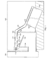
- FIGS. 1 through 3 diagrams of a generalized architecture of a fuel tank system having an exemplary pressure regulating float valve 100 may be shown.
- This system may allow greater flexibility in the design of fuel tank structure, fuel tank vent systems or other fuel tank systems such as a fuel transfer or onboard inert gas generation system.
- the float valve 100 may function like a typical float valve until pressure in the tank 102 is increased beyond a threshold.
- the fuel tank 102 may be positioned within a wing of an aircraft.
- the fuel tank 102 may have a positive dihedral that may use the pressure regulating float valve 100 at the wing tips to prevent fuel transfer during rotation from the wing fuel tank 102 to the surge tank 106.
- a conduit 104 may open into the main fuel tank 102.
- the conduit 104 may enter the tank 102 from a bottom portion and extend upwards.
- the conduit 104 typically rises above the maximum level of fuel 124.
- the conduit 104 may exit into a surge tank 106.
- the surge tank 106 may receive ullage flow from the fuel tank 102 when a pressure differential exists between the surge tank 106 and the wing fuel tank 102.
- the opening 108 of the conduit 104 into the fuel tank 102 may be of various configurations.
- the opening 108 of the conduit 104 into the fuel tank 102 may be circular, square or other shape and may depend on the conduit 104.
- a first edge 150 and a second edge 152 may be provided at the top of the conduit 104.
- the first edge 150 may have a hinge 112.
- the hinge 112 may pivotally connect the pressure regulating float valve 100. Two or more hinges 112 may be used for connecting the valve 100.
- the hinge 112 connected to the first edge 150 may rotate the length of the float valve 100 in a clockwise or counter-clockwise direction. This rotation may generally be circular.
- the fuel tank 102 may have a height such that the float valve 100 may be pivoted up and down.
- the height of the conduit 104 extending into the fuel tank 102 may also be adjusted so that the float valve 100 may have sufficient clearance to be pivoted.
- the pressure regulating float valve 100 may include an arm connected to a hinge 112, seal plate 132 and buoyant member 122.
- a first section 116 of the arm may be connected to the hinge 112.
- the first section 116 may be connected to the second section 118 of the arm.
- the intersection of the first section 116 and the second section 118 may contact the second edge 152 of the conduit 104.
- the contact point at the second edge 152 of the conduit 104 may limit the amount of float valve 100 travel within the fuel tank 102.
- the second section 118 of the arm may have a higher and lower point.
- the higher point of the second section 118 may be connected with the first section 116.
- the lower point of the second section 118 may be connected to the flat section 120 of the float valve 100 and may be positioned to correspond with normal fuel levels within the fuel tank 102.
- the second section 118 may be adjusted. For example, the second section 118 may be adjusted such that the lower point extends far into the fuel tank 102. The fuel tank 102 may then have a deeper configuration.
- the second section 118 of the arm may be connected to the flat section 120.
- the flat section 120 may provide a stable support for a buoyant member 122.
- the arm may be connected to the buoyant member 122 directly without the flat section 120.
- the buoyant member 122 may be at a distal end from the hinge 112 connecting the first section 116 of the arm.
- the buoyant member 122 may have less of a density than the fuel 124 within the fuel tank 102, which may allow the buoyant member 122 to float above the level of fuel 124.
- the density of the buoyant member 122 may be adjusted.
- the buoyancy of the member 122 may also take into account of the weight of the float valve 100 or portions thereof.
- the pressure regulating float valve 100 may have a seal plate 132.
- the seal plate 132 may be the size of the opening 108 of the conduit 104. In one embodiment, the seal plate 132 may be enlarged such that the contact made between the seal plate 132 may touch the first edge 150 and the second edge 152 of the conduit 104. In one embodiment, the seal plate 132 may be prevented from rising above the conduit 104 through the first edge 150 and the second edge 152. When the float valve 100 is raised, the seal plate 132 may cover the opening 108.
- the seal plate 132 may be connected to the float valve 100 through a structure 130 as shown in Figures 1 through 3 .
- the structure 130 may be connected to the first section 116.
- the structure 130 may be connected at an angle to the first section 116.
- the structure 130 may be connected to a center portion of the seal plate 132.
- the seal plate 132 may be circular, square or other shape and may depend on the opening 108 of the conduit 104 into the fuel tank 102.
- the structure 130 may extend into the conduit 104. This extension may place the seal plate 132 well within the conduit 104. When unsealed, the seal plate 132 may rest within the conduit 104. Because of the contact point at the second edge 152 of the conduit, the seal plate 132 may be suspended and not contact the walls within the conduit 104. When sealed, the structure 130 may raise above the opening 108 due to the float valve mechanism 100 rising with the buoyant member 122.
- the pressure regulating float valve 100 may be designed to open when the tank pressure threshold is exceeded by properly sizing the buoyant member 122 and the seal plate 132.
- the opening 108 may relieve the pressure within the tank 102.
- the float valve 100 may close. Typically, this may occur assuming the level of the fuel 124 has not changed.
- valve 100 When the level of fuel 124 is decreased, the valve 100 may open.
- the pressure regulating float valve 100 may limit the pressure rather than relying on controls within other systems to limit pressure generation within the tank.
- additional optimization of vent line sizes and tank pressure limits may be realized.
- FIG. 1 a diagram of the generalized architecture of the fuel tank 102 having the exemplary pressure regulating float valve 100 in a lowered position may be shown.
- the low level of fuel 124 may be followed by the buoyant member 122.
- the valve 100 may be pivoted through the hinge 112 in a downward direction.
- the second edge 152 of the conduit 104 may prevent the float valve 100 from pivoting downwards fully.
- the seal plate 132 may be unseated from the opening 108 placing it in an unsealed position.
- a portion or the entire length of the structure 130 may be positioned within the conduit 104.
- the seal plate 132 may be within the conduit 104.
- FIG. 2 a diagram of the exemplary pressure regulating float valve 100 in an elevated or sealed position may be shown.
- the level of fuel 124 may increase causing the buoyancy member 122 to rise.
- the valve 100 may be placed in a sealing position when the level of fuel 124 reaches a predetermined limit. Through the hinge 112, the valve 100 may have moved in a counter-clockwise circular motion.
- the flat section 120 connected to the second section 118 may have also risen.
- the seal plate 132 may be brought upwards in contact with the first edge 150 and the second edge 152 of the conduit 104 through the float valve 100. The first edge 150 and the second edge 152 may prevent the seal plate 132 from being moved out of the conduit 104.
- the structure 130 may be positioned outside the conduit 104 and may seal the opening 108 with the seal plate 132. The seal plate 132 may make a tight seal to the opening 108 and may depend on the height of the buoyant member 122. By closing the opening 108 of the conduit 104 into the fuel tank 102, the float valve 100 may protect fuel 124 from spilling into the surge tank 106 through the conduit 104.
- FIG. 3 a diagram of the exemplary pressure regulating float valve 100 having its seal plate 132 forced down because of ullage pressure may be shown. Ullage pressure on the seal plate 132 may create a moment arm in the opposite direction, that is, downwards. At a particular pressure threshold, the float valve 100, due to the seal plate 132, may open to relieve the pressure. This may result in an actuated float valve 100 that may be pressure regulating. The float valve 100 may allow for positive ullage pressure to remove the sealing from the opening 108 of the conduit 104 and properly vent.
- the pressure on the seal plate 132 may bring down the structure 130.
- the structure 130 may bring the first section 116 downwards through the hinge 112. This may bring the second section 118 downwards along with the flat section 120.
- the flat section 120 and the buoyant member 122 may then be positioned below the fuel 124 or a portion thereof as shown in Figure 3 .
- the increased ullage pressure may force the seal plate 132 downwards and may allow the pressure to escape through the conduit 104.
- the seal plate 132 may no longer contact the first edge 150 and the second edge 152 of the conduit 104.
- the seal plate 132 may rise up again due to the buoyant member 122 and the fuel 124.
- the valve 100 may then pivotally rotate around the hinge 112. The float valve 100 may then lower the seal plate 132 connected to the structure 130.
- the pressure regulating float valve 100 may close when the level of fuel 124 is above the conduit 104 or slightly there below. Sections within the float valve 100 or the buoyant member 122 may be adjusted. The increase in fuel 124 may tighten the sealing of the opening 108 on the conduit 104. This may prevent fuel from entering into the surge tank 106 in such conditions.
- the float valve 100 may determine whether there has been an increase or decrease in fuel 124. Through the buoyant member 122 connected to the flat section 120 of the float valve 100, increases or decreases of fuel 124 may be detected. The buoyant member 122 may be connected at a distal end from the hinge 112 that allows the buoyant member 122 to move up and down. The buoyant member 122 along with the other sections of the float valve 100 may move in a circular motion.
- the float valve 100 When the fuel 124 level is decreased, the float valve 100 may be lowered at block 404.
- the first section 116, second section 118, flat section 120 and buoyant member 122 may pivot downwards around the hinge 112 in a clockwise direction as shown in Figure 1 .
- the structure 130 goes down into the conduit 104 that brings the seal plate 132 more within the conduit 104. If the fuel 124 is low enough, the float valve 100 may contact the second edge 152 of the conduit 104.
- the processes may end at block 412.
- the float valve 100 may be raised when the level of fuel 124 increases at block 406.
- the valve 100 may begin moving in a counter-clockwise direction around the hinge 112 in a circular motion.
- the float valve 100 may be raised through the buoyant member 122 as shown in Figure 2 .
- the fuel 124 level may increase to the point where the structure 130 connected to the seal plate 132 is no longer in the conduit 104.
- the seal plate 132 may begin to rise with the buoyant member 122 until the seal plate 132 reaches the opening 108.
- the opening 108 may shut preventing fuel 124 spillage into the surge tank 106 through the conduit 104.
- a determination may be made whether the ullage pressure has reached a threshold value within the fuel tank 124.
- the ullage pressure may occur when the fuel tank 102 pressure is increasing and vent openings are closed due to the quantity of fuel 124.
- the processes for regulating pressure may end at block 412.
- the float valve 100 may be lowered or the pressure may be regulated constantly when the opening 108 is closed.
- the seal plate 132 When the ullage pressure has reached a threshold value within the tank 102, relative to the surge tank pressure, at block 410, the seal plate 132 may be pushed downwards as shown in Figure 3 . Due to the configuration of the seal plate 132, the pressure may be exerted down on the seal plate 132. The float valve 412 may be lowered clockwise in a circular manner and may be pivoted around the hinge 112.
- the float valve 100 may once again be lifted upwards sealing the opening 108 to prevent fuel 124 spillage.
- the processes may end at block 412. A combination of the processes described above may be used and do not necessarily have to occur in the order presented above. For example, the float valve 100 may go upwards and downwards several times before the seal plate 132 is forced downwards to remove the ullage pressure.
Landscapes
- Engineering & Computer Science (AREA)
- General Engineering & Computer Science (AREA)
- Aviation & Aerospace Engineering (AREA)
- Mechanical Engineering (AREA)
- Cooling, Air Intake And Gas Exhaust, And Fuel Tank Arrangements In Propulsion Units (AREA)
- Float Valves (AREA)
- Self-Closing Valves And Venting Or Aerating Valves (AREA)
Abstract
Description
- Embodiments of this disclosure generally relate to vent systems in aircraft, and more particularly, to a pressure regulating float valve for the control of fuel entering into a fuel surge tank from the wing fuel tank of a fuel system.
- Aircraft with swept wings and integral wing fuel tanks may use float valves on their outboard tanks to prevent excess fuel transfer to the fuel surge tanks during rotation or other maneuvers. The float valve may have a float and seal plate inside the wing fuel tank. The float valve may have a see-saw type pivot design. The float valve may be opened to allow for pressure equalization between the wing fuel tank and the surge fuel tank.
- During certain maneuvers on the ground and in flight, fuel movement within the fuel tanks may result in the float valves closing and preventing the wing tank from venting. If the pressure inside the tank increases significantly due to altitude changes or fuel transfer or inert gas injection while the float valve is closed, damage to the fuel tank structure may occur. Alternatively, the tank structure may be suitably sized to withstand such pressure increases. However, this may increase the weight of the airplane and affect performance.
- Therefore, it would be desirable to provide a vent system for an aircraft and methods thereof that overcome the above problems.
- A fuel system for an aircraft has a vent system. The vent system has a subsystem element, the pressure regulating float valve. The float valve has a conduit opening connecting the wing fuel tank and fuel surge tank. The float valve has a member connected to the conduit at a proximal end. The member has a seal plate within the conduit sealing the opening into the fuel surge tank section when a buoyant section at a distal end rises along with the cover through the member with a rise in fluid level within the fuel section.
- The subsystem element has a housing. The housing has a main section and a conduit opening into the main section. The subsystem element has a pressure regulating float valve mechanism. The float valve mechanism has a beam pivotally connected to a top of the main section at a proximal end. The float valve mechanism has a buoyant member connected at a distal end and a seal plate connected to the beam through a structure, the structure extending the seal plate into the conduit. The buoyant member raises the seal plate and the structure through the beam and closes the opening into the main section with an increase of fluid within the main section.
- A method for regulating pressure in a vent system for an aircraft comprises: pivoting a beam around a hinge connected to a conduit when a buoyant member connected at a distal end rises with an increase of fluid level within a fuel tank; raising a seal plate within the conduit through the beam sealing an opening of the conduit when the fluid level within the fuel tank is at or above a predefined limit; and removing the sealing when a threshold value of pressure builds up in the fuel tank by depressing the seal plate, and thereby submerging the beam, and the buoyant member.
- The features, functions, and advantages may be achieved independently in various embodiments of the disclosure or may be combined in yet other embodiments.
- According to an aspect of the present invention there is provided a vent system for an aircraft comprising a fuel section, a conduit opening into the fuel section, and a member connected to the conduit at a proximal end having a seal plate within the conduit sealing the opening into the fuel section when a buoyant section at a distal end rises along with the seal plate through the member with a rise in fluid level within the fuel section. Advantageously the sealing is removed when the fluid level within the fuel section is reduced. Advantageously the sealing is removed when a threshold of ullage pressure builds up within the fuel section and forces the seal plate downwards. Preferably the ullage pressure forces the buoyant section to lower below the fluid level within the fuel section. Advantageously the conduit comprises an opening into a surge tank. Advantageously the conduit opening into the fuel section comprises a first edge pivoting the member at the proximal end and a second edge contacting the member when fluid level within the fuel section is low. Advantageously the member connected to the conduit is connected to the first edge through a hinge. Advantageously the member is connected to the seal plate through a structure. Advantageously a resiliency of the buoyant section is adjustable. Advantageously the member is connected to a top of the conduit. Advantageously the conduit extends into a lower portion of the fuel section and the opening into the fuel section rises upwards.
- According to an aspect of the present invention there is provided a system comprising a housing having a main section and a conduit opening into the main section, and a pressure regulating float valve comprising a beam pivotally connected to a top of the conduit at a proximal end, a buoyant member connected at a distal end, a seal plate connected to the beam through a structure, the structure extending the seal plate into the conduit wherein the buoyant member raises the seal plate and the structure through the beam and closes the opening into the main section with an increase of fluid within the main section. Advantageously the beam comprises a first section connected to the conduit opening through a hinge, a second section connected to the first section, and a flat section connected to the second section. Preferably the first section and second section contact the conduit at a point on the conduit opposite from the hinge. Advantageously the seal plate overlaps the opening into the main section preventing fuel spillage. Advantageously the conduit comprises a first edge and a second edge preventing the seal plate from rising above the conduit.
- According to an aspect of the present invention there is provided a method for regulating pressure in a vent system for an aircraft comprising pivoting a beam around a hinge connected to a conduit when a buoyant member connected at a distal end rises with a rise of fluid level within a fuel tank, raising a seal plate within the conduit through the beam sealing an opening of the conduit when the fluid level within the fuel tank is at or above a predefined limit, and removing the sealing by depressing the seal plate when a threshold value of pressure is exceeded in the fuel tank, and correspondingly submerging the beam and buoyant member. Advantageously the step of pivoting the beam comprises rotating the beam around the hinge. Preferably lowering the beam when the buoyant member connected to the beam drops with a lowering of fluid level within the fuel tank. Preferably sealing the opening of the conduit within the fuel tank prevents fuel spillage.
- Embodiments of the disclosure will become more fully understood from the detailed description and the accompanying drawings, wherein:
-
Figure 1 is a diagram of a generalized architecture of a fuel tank having an exemplary pressure regulating float valve in a lowered position; -
Figure 2 is a diagram of the exemplary pressure regulating float valve in a raised position; -
Figure 3 is a diagram of the exemplary pressure regulating float valve having its seal plate forced down because of ullage pressure; and -
Figure 4 is a flow chart having illustrative processes for regulating pressure through the float valve. - Referring to
Figures 1 through 3 , diagrams of a generalized architecture of a fuel tank system having an exemplary pressure regulatingfloat valve 100 may be shown. This system may allow greater flexibility in the design of fuel tank structure, fuel tank vent systems or other fuel tank systems such as a fuel transfer or onboard inert gas generation system. Thefloat valve 100 may function like a typical float valve until pressure in thetank 102 is increased beyond a threshold. - The
fuel tank 102 may be positioned within a wing of an aircraft. Thefuel tank 102 may have a positive dihedral that may use the pressure regulatingfloat valve 100 at the wing tips to prevent fuel transfer during rotation from thewing fuel tank 102 to thesurge tank 106. - A
conduit 104 may open into themain fuel tank 102. Theconduit 104 may enter thetank 102 from a bottom portion and extend upwards. Theconduit 104 typically rises above the maximum level offuel 124. At one end, theconduit 104 may exit into asurge tank 106. Thesurge tank 106 may receive ullage flow from thefuel tank 102 when a pressure differential exists between thesurge tank 106 and thewing fuel tank 102. - The
opening 108 of theconduit 104 into thefuel tank 102 may be of various configurations. Theopening 108 of theconduit 104 into thefuel tank 102 may be circular, square or other shape and may depend on theconduit 104. At the top of theconduit 104, afirst edge 150 and asecond edge 152 may be provided. Thefirst edge 150 may have ahinge 112. Thehinge 112 may pivotally connect the pressure regulatingfloat valve 100. Two ormore hinges 112 may be used for connecting thevalve 100. Thehinge 112 connected to thefirst edge 150 may rotate the length of thefloat valve 100 in a clockwise or counter-clockwise direction. This rotation may generally be circular. In one embodiment, thefuel tank 102 may have a height such that thefloat valve 100 may be pivoted up and down. The height of theconduit 104 extending into thefuel tank 102 may also be adjusted so that thefloat valve 100 may have sufficient clearance to be pivoted. - The pressure regulating
float valve 100 may include an arm connected to ahinge 112,seal plate 132 andbuoyant member 122. Afirst section 116 of the arm may be connected to thehinge 112. At a distal end, thefirst section 116 may be connected to thesecond section 118 of the arm. The intersection of thefirst section 116 and thesecond section 118 may contact thesecond edge 152 of theconduit 104. The contact point at thesecond edge 152 of theconduit 104 may limit the amount offloat valve 100 travel within thefuel tank 102. - The
second section 118 of the arm may have a higher and lower point. The higher point of thesecond section 118 may be connected with thefirst section 116. The lower point of thesecond section 118 may be connected to theflat section 120 of thefloat valve 100 and may be positioned to correspond with normal fuel levels within thefuel tank 102. Thesecond section 118 may be adjusted. For example, thesecond section 118 may be adjusted such that the lower point extends far into thefuel tank 102. Thefuel tank 102 may then have a deeper configuration. - Continuing with
Figures 1 through 3 , thesecond section 118 of the arm may be connected to theflat section 120. Theflat section 120 may provide a stable support for abuoyant member 122. In one embodiment, the arm may be connected to thebuoyant member 122 directly without theflat section 120. Thebuoyant member 122 may be at a distal end from thehinge 112 connecting thefirst section 116 of the arm. Typically, thebuoyant member 122 may have less of a density than thefuel 124 within thefuel tank 102, which may allow thebuoyant member 122 to float above the level offuel 124. The density of thebuoyant member 122 may be adjusted. The buoyancy of themember 122 may also take into account of the weight of thefloat valve 100 or portions thereof. - The pressure regulating
float valve 100 may have aseal plate 132. Theseal plate 132 may be the size of theopening 108 of theconduit 104. In one embodiment, theseal plate 132 may be enlarged such that the contact made between theseal plate 132 may touch thefirst edge 150 and thesecond edge 152 of theconduit 104. In one embodiment, theseal plate 132 may be prevented from rising above theconduit 104 through thefirst edge 150 and thesecond edge 152. When thefloat valve 100 is raised, theseal plate 132 may cover theopening 108. - The
seal plate 132 may be connected to thefloat valve 100 through astructure 130 as shown inFigures 1 through 3 . Thestructure 130 may be connected to thefirst section 116. Thestructure 130 may be connected at an angle to thefirst section 116. Thestructure 130 may be connected to a center portion of theseal plate 132. Theseal plate 132 may be circular, square or other shape and may depend on theopening 108 of theconduit 104 into thefuel tank 102. - In one embodiment, the
structure 130 may extend into theconduit 104. This extension may place theseal plate 132 well within theconduit 104. When unsealed, theseal plate 132 may rest within theconduit 104. Because of the contact point at thesecond edge 152 of the conduit, theseal plate 132 may be suspended and not contact the walls within theconduit 104. When sealed, thestructure 130 may raise above theopening 108 due to thefloat valve mechanism 100 rising with thebuoyant member 122. - As shown in
Figures 1 through 3 , the pressure regulatingfloat valve 100 may be designed to open when the tank pressure threshold is exceeded by properly sizing thebuoyant member 122 and theseal plate 132. Theopening 108 may relieve the pressure within thetank 102. When the pressure drops below the threshold, thefloat valve 100 may close. Typically, this may occur assuming the level of thefuel 124 has not changed. - When the level of
fuel 124 is decreased, thevalve 100 may open. Advantageously, the pressure regulatingfloat valve 100 may limit the pressure rather than relying on controls within other systems to limit pressure generation within the tank. In addition, additional optimization of vent line sizes and tank pressure limits may be realized. - As depicted in
Figure 1 , a diagram of the generalized architecture of thefuel tank 102 having the exemplary pressure regulatingfloat valve 100 in a lowered position may be shown. The low level offuel 124 may be followed by thebuoyant member 122. Thevalve 100 may be pivoted through thehinge 112 in a downward direction. Thesecond edge 152 of theconduit 104 may prevent thefloat valve 100 from pivoting downwards fully. As shown, theseal plate 132 may be unseated from theopening 108 placing it in an unsealed position. A portion or the entire length of thestructure 130 may be positioned within theconduit 104. Theseal plate 132 may be within theconduit 104. - Turning to
Figure 2 , a diagram of the exemplary pressure regulatingfloat valve 100 in an elevated or sealed position may be shown. The level offuel 124 may increase causing thebuoyancy member 122 to rise. Thevalve 100 may be placed in a sealing position when the level offuel 124 reaches a predetermined limit. Through thehinge 112, thevalve 100 may have moved in a counter-clockwise circular motion. Theflat section 120 connected to thesecond section 118 may have also risen. - The
seal plate 132 may be brought upwards in contact with thefirst edge 150 and thesecond edge 152 of theconduit 104 through thefloat valve 100. Thefirst edge 150 and thesecond edge 152 may prevent theseal plate 132 from being moved out of theconduit 104. Thestructure 130 may be positioned outside theconduit 104 and may seal theopening 108 with theseal plate 132. Theseal plate 132 may make a tight seal to theopening 108 and may depend on the height of thebuoyant member 122. By closing theopening 108 of theconduit 104 into thefuel tank 102, thefloat valve 100 may protectfuel 124 from spilling into thesurge tank 106 through theconduit 104. - When ullage pressure begins to increase within the space between the
fuel 124 and the top of thetank 102, pressurization of thewing fuel tank 102 may occur. Provided inFigure 3 , a diagram of the exemplary pressure regulatingfloat valve 100 having itsseal plate 132 forced down because of ullage pressure may be shown. Ullage pressure on theseal plate 132 may create a moment arm in the opposite direction, that is, downwards. At a particular pressure threshold, thefloat valve 100, due to theseal plate 132, may open to relieve the pressure. This may result in an actuatedfloat valve 100 that may be pressure regulating. Thefloat valve 100 may allow for positive ullage pressure to remove the sealing from theopening 108 of theconduit 104 and properly vent. - The pressure on the
seal plate 132 may bring down thestructure 130. Thestructure 130 may bring thefirst section 116 downwards through thehinge 112. This may bring thesecond section 118 downwards along with theflat section 120. Theflat section 120 and thebuoyant member 122 may then be positioned below thefuel 124 or a portion thereof as shown inFigure 3 . - The increased ullage pressure may force the
seal plate 132 downwards and may allow the pressure to escape through theconduit 104. Theseal plate 132 may no longer contact thefirst edge 150 and thesecond edge 152 of theconduit 104. Once the pressure is removed, theseal plate 132 may rise up again due to thebuoyant member 122 and thefuel 124. When the level offuel 124 lowers, thevalve 100 may then pivotally rotate around thehinge 112. Thefloat valve 100 may then lower theseal plate 132 connected to thestructure 130. - In one embodiment, the pressure regulating
float valve 100 may close when the level offuel 124 is above theconduit 104 or slightly there below. Sections within thefloat valve 100 or thebuoyant member 122 may be adjusted. The increase infuel 124 may tighten the sealing of theopening 108 on theconduit 104. This may prevent fuel from entering into thesurge tank 106 in such conditions. - Referring to
Figure 4 , a flow chart having illustrative processes for regulating pressure through thefloat valve 100 may be described. The processes may begin atblock 400. Atdecision block 402, thefloat valve 100 may determine whether there has been an increase or decrease infuel 124. Through thebuoyant member 122 connected to theflat section 120 of thefloat valve 100, increases or decreases offuel 124 may be detected. Thebuoyant member 122 may be connected at a distal end from thehinge 112 that allows thebuoyant member 122 to move up and down. Thebuoyant member 122 along with the other sections of thefloat valve 100 may move in a circular motion. - When the
fuel 124 level is decreased, thefloat valve 100 may be lowered atblock 404. Thefirst section 116,second section 118,flat section 120 andbuoyant member 122 may pivot downwards around thehinge 112 in a clockwise direction as shown inFigure 1 . At the same time, thestructure 130 goes down into theconduit 104 that brings theseal plate 132 more within theconduit 104. If thefuel 124 is low enough, thefloat valve 100 may contact thesecond edge 152 of theconduit 104. The processes may end atblock 412. - Returning to decision block 402, the
float valve 100 may be raised when the level offuel 124 increases atblock 406. Thevalve 100 may begin moving in a counter-clockwise direction around thehinge 112 in a circular motion. Thefloat valve 100 may be raised through thebuoyant member 122 as shown inFigure 2 . - Continuing with
Figure 4 , thefuel 124 level may increase to the point where thestructure 130 connected to theseal plate 132 is no longer in theconduit 104. Theseal plate 132 may begin to rise with thebuoyant member 122 until theseal plate 132 reaches theopening 108. When enough pressure is applied upwards by thebuoyant member 122, theopening 108 may shut preventingfuel 124 spillage into thesurge tank 106 through theconduit 104. - At
decision block 408, a determination may be made whether the ullage pressure has reached a threshold value within thefuel tank 124. The ullage pressure may occur when thefuel tank 102 pressure is increasing and vent openings are closed due to the quantity offuel 124. When the threshold has not been reached, the processes for regulating pressure may end atblock 412. Thefloat valve 100 may be lowered or the pressure may be regulated constantly when theopening 108 is closed. - When the ullage pressure has reached a threshold value within the
tank 102, relative to the surge tank pressure, atblock 410, theseal plate 132 may be pushed downwards as shown inFigure 3 . Due to the configuration of theseal plate 132, the pressure may be exerted down on theseal plate 132. Thefloat valve 412 may be lowered clockwise in a circular manner and may be pivoted around thehinge 112. - By removing the seal from the
opening 108, the ullage pressure may escape to thesurge tank 106. After the pressure is removed, thefloat valve 100 may once again be lifted upwards sealing theopening 108 to preventfuel 124 spillage. The processes may end atblock 412. A combination of the processes described above may be used and do not necessarily have to occur in the order presented above. For example, thefloat valve 100 may go upwards and downwards several times before theseal plate 132 is forced downwards to remove the ullage pressure. - While embodiments of the disclosure have been described in terms of various specific embodiments, those skilled in the art will recognize that the embodiments of the disclosure may be practiced with modifications within the spirit and scope of the claims.
Claims (14)
- A vent system for an aircraft comprising:a fuel tank (102); a conduit 104 opening into the fuel tank (124); anda valve (100) connected to the conduit (104) at a proximal end having a seal plate (132) within the conduit (104) sealing the opening (108) into the fuel tank (124) when a buoyant member (122) at a distal end rises along with the seal plate (132) through the member with a rise in fluid level within the fuel tank (102).
- A vent system for an aircraft in accordance with Claim 1, wherein the sealing is removed when the fluid level within the fuel section is reduced.
- A vent system for an aircraft in accordance with Claim 1 or Claim 2, wherein the sealing is removed when a threshold of ullage pressure builds up within the fuel section and forces the seal plate (132) downwards.
- A vent system for an aircraft in accordance with any of the preceding claims, wherein the ullage pressure forces the buoyant member (122) to lower below the fluid level within the fuel tank (102).
- A vent system for an aircraft in accordance with any of the preceding claims, wherein the conduit (104) comprises an opening into a surge tank (106).
- A vent system for an aircraft in accordance with any of the preceding claims, wherein the conduit (104) opening into the fuel tank (102) comprises a first edge (150) pivoting the valve (100) at the proximal end and a second edge (152) contacting the member when fluid level within the fuel tank (102) is low.
- A vent system for an aircraft in accordance with any of the preceding claims, wherein the valve (100) connected to the conduit (104) is connected to the first edge through a hinge (112).
- A vent system for an aircraft in accordance with any of the preceding claims, wherein the valve (100) is connected to the seal plate (132) through a structure (130).
- A vent system for an aircraft in accordance with any of the preceding claims, wherein a resiliency of the buoyant member (122) is adjustable.
- A vent system for an aircraft in accordance with any of the preceding claims, wherein the conduit (104) extends into a lower portion of the fuel tank (102) and the opening into the fuel tank (102) rises upwards.
- A method for regulating pressure in a vent system for an aircraft comprising:pivoting a beam around a hinge (112) connected to a conduit (104) when a buoyant member (122) connected at a distal end rises with a rise of fluid level within a fuel tank (102);raising a seal plate (132) within the conduit (140) through the beam;sealing an opening of the conduit when the fluid level within the fuel tank (102) is at or above a predefined limit; andremoving the sealing by depressing the seal plate (132) when a threshold value of pressure is exceeded in the fuel tank (102), and correspondingly submerging the beam and buoyant member (122).
- A method for regulating pressure in a vent system for an aircraft in accordance with Claim 11, wherein pivoting the beam comprises rotating the beam around the hinge (112).
- A method for regulating pressure in a vent system for an aircraft in accordance with Claim 11 or 12, comprising lowering the beam when the buoyant member (122) connected to the beam drops with a lowering of fluid level within the fuel tank (102).
- A method for regulating pressure in a vent system for an aircraft in accordance with any of claims 11 to 13, wherein sealing the opening of the conduit within the fuel tank (102) prevents fuel spillage.
Applications Claiming Priority (1)
| Application Number | Priority Date | Filing Date | Title |
|---|---|---|---|
| US13/278,900 US8596289B2 (en) | 2011-10-21 | 2011-10-21 | Pressure regulating float valve |
Publications (3)
| Publication Number | Publication Date |
|---|---|
| EP2584233A2 true EP2584233A2 (en) | 2013-04-24 |
| EP2584233A3 EP2584233A3 (en) | 2017-10-25 |
| EP2584233B1 EP2584233B1 (en) | 2020-03-11 |
Family
ID=47002759
Family Applications (1)
| Application Number | Title | Priority Date | Filing Date |
|---|---|---|---|
| EP12188262.5A Active EP2584233B1 (en) | 2011-10-21 | 2012-10-12 | Pressure regulating float valve |
Country Status (2)
| Country | Link |
|---|---|
| US (1) | US8596289B2 (en) |
| EP (1) | EP2584233B1 (en) |
Families Citing this family (4)
| Publication number | Priority date | Publication date | Assignee | Title |
|---|---|---|---|---|
| US8997780B2 (en) * | 2011-06-10 | 2015-04-07 | Hamilton Sundstrand Corporation | Fuel float valve |
| US10921829B1 (en) | 2014-10-29 | 2021-02-16 | Jeremie Thornburg | Aligned-outlet and distal-flushable blow case |
| US10036406B1 (en) * | 2014-10-29 | 2018-07-31 | Jeremie Thornburg | Aligned-outlet and distal-flushable blow case |
| US12270690B2 (en) * | 2020-11-03 | 2025-04-08 | Parker-Hannifin Corporation | Negative space fuel tank gauging system and ullage gas control |
Family Cites Families (13)
| Publication number | Priority date | Publication date | Assignee | Title |
|---|---|---|---|---|
| US1511163A (en) * | 1922-06-28 | 1924-10-07 | Norddeutsche Kuhlerfabrik A G | Fuel-feeding system for carburetors |
| US1841663A (en) * | 1929-05-23 | 1932-01-19 | Bendix Stromberg Carburetor Co | Aircraft carburetor and fuel supply system |
| US2845937A (en) | 1953-12-01 | 1958-08-05 | Aero Supply Mfg Co Inc | Aircraft tank vent valve |
| GB1052616A (en) * | 1964-05-14 | |||
| GB1342086A (en) * | 1970-04-27 | 1973-12-25 | Sykes Ltd Henry | Fluid flow control valves |
| US3691730A (en) * | 1971-05-18 | 1972-09-19 | Parker Hannifin Corp | Fuel tank inerting system |
| US3782400A (en) * | 1972-03-17 | 1974-01-01 | Xar Ind Inc | Valving system for supplying fuel to tanks and transferring fuel between tanks |
| US3948626A (en) * | 1974-10-25 | 1976-04-06 | Parker-Hannifin Corporation | Refueling equipment for aircraft fuel tanks and the like |
| GB1560646A (en) * | 1976-10-20 | 1980-02-06 | Millars Wellpoint Int | Liquid level controlled valve |
| US4796650A (en) * | 1987-12-01 | 1989-01-10 | Hwang Biing Yih | Structure for a float valve assembly |
| US5031655A (en) | 1990-03-19 | 1991-07-16 | The Boeing Company | Self-locking vent valve |
| US5901744A (en) * | 1996-09-06 | 1999-05-11 | Richards; Samuel K. | Water supply system for a water source with limited flow capability |
| US7469725B2 (en) * | 2006-02-22 | 2008-12-30 | Honeywell International Inc. | Method and apparatus for accurately delivering a predetermined amount of fuel to a vehicle |
-
2011
- 2011-10-21 US US13/278,900 patent/US8596289B2/en active Active
-
2012
- 2012-10-12 EP EP12188262.5A patent/EP2584233B1/en active Active
Non-Patent Citations (1)
| Title |
|---|
| None |
Also Published As
| Publication number | Publication date |
|---|---|
| EP2584233B1 (en) | 2020-03-11 |
| EP2584233A3 (en) | 2017-10-25 |
| US8596289B2 (en) | 2013-12-03 |
| US20130098451A1 (en) | 2013-04-25 |
Similar Documents
| Publication | Publication Date | Title |
|---|---|---|
| US8596289B2 (en) | Pressure regulating float valve | |
| EP2847018B1 (en) | Quick response float-operated vapor vent valve | |
| US6371146B1 (en) | Peelaway type rollover valve element | |
| US9360127B2 (en) | Control valve | |
| CN1046993C (en) | Pressure reducing valves for pressure equalization between enclosed spaces and the surrounding atmosphere | |
| JP6806870B2 (en) | Overpressure prevention fuel tank | |
| JP2013166511A (en) | Valve apparatus for hold | |
| US2845937A (en) | Aircraft tank vent valve | |
| US4376446A (en) | Vent valve for fuel tanks and the like | |
| CN210531726U (en) | Exhaust valve | |
| KR101257713B1 (en) | Vent valve | |
| CN112407305B (en) | Breather valve for helicopter fuel system | |
| EP2532590A1 (en) | Fuel float valve | |
| EP2852505B1 (en) | Vent valve | |
| CN110118263A (en) | A kind of New flat valve | |
| US9399395B2 (en) | Tank provided with an over-pressure valve | |
| SE462603B (en) | VALVE DEVICE, IN PARTICULAR, LEAD THE URL EXHAUST TO A VEHICLE BRANCH TANK | |
| JP2024510639A (en) | Ship vibration damper system | |
| US4794946A (en) | Inherently adjustable inverted cup float for a ballcock valve | |
| CN204176103U (en) | Cross-country type fuel tank float type topples over anti-overflow respiratory system | |
| CN200961095Y (en) | Automatic oil tank emptying anti-overflow valve | |
| KR101257712B1 (en) | High-level valve | |
| KR101257710B1 (en) | Refuel-defuel valve | |
| CN219119948U (en) | Micro-pressure lip-shaped sealing structure | |
| CN214654675U (en) | Float connecting rod mechanism mounted at top of oil-gas separator |
Legal Events
| Date | Code | Title | Description |
|---|---|---|---|
| PUAI | Public reference made under article 153(3) epc to a published international application that has entered the european phase |
Free format text: ORIGINAL CODE: 0009012 |
|
| 17P | Request for examination filed |
Effective date: 20121012 |
|
| AK | Designated contracting states |
Kind code of ref document: A2 Designated state(s): AL AT BE BG CH CY CZ DE DK EE ES FI FR GB GR HR HU IE IS IT LI LT LU LV MC MK MT NL NO PL PT RO RS SE SI SK SM TR |
|
| AX | Request for extension of the european patent |
Extension state: BA ME |
|
| REG | Reference to a national code |
Ref country code: DE Ref legal event code: R079 Ref document number: 602012068361 Country of ref document: DE Free format text: PREVIOUS MAIN CLASS: F16K0024040000 Ipc: B64D0037320000 |
|
| PUAL | Search report despatched |
Free format text: ORIGINAL CODE: 0009013 |
|
| AK | Designated contracting states |
Kind code of ref document: A3 Designated state(s): AL AT BE BG CH CY CZ DE DK EE ES FI FR GB GR HR HU IE IS IT LI LT LU LV MC MK MT NL NO PL PT RO RS SE SI SK SM TR |
|
| AX | Request for extension of the european patent |
Extension state: BA ME |
|
| RIC1 | Information provided on ipc code assigned before grant |
Ipc: B64D 37/22 20060101ALI20170919BHEP Ipc: F16K 24/04 20060101ALI20170919BHEP Ipc: F16K 31/22 20060101ALI20170919BHEP Ipc: B64D 37/32 20060101AFI20170919BHEP |
|
| STAA | Information on the status of an ep patent application or granted ep patent |
Free format text: STATUS: EXAMINATION IS IN PROGRESS |
|
| 17Q | First examination report despatched |
Effective date: 20190109 |
|
| GRAP | Despatch of communication of intention to grant a patent |
Free format text: ORIGINAL CODE: EPIDOSNIGR1 |
|
| STAA | Information on the status of an ep patent application or granted ep patent |
Free format text: STATUS: GRANT OF PATENT IS INTENDED |
|
| INTG | Intention to grant announced |
Effective date: 20190816 |
|
| GRAJ | Information related to disapproval of communication of intention to grant by the applicant or resumption of examination proceedings by the epo deleted |
Free format text: ORIGINAL CODE: EPIDOSDIGR1 |
|
| STAA | Information on the status of an ep patent application or granted ep patent |
Free format text: STATUS: EXAMINATION IS IN PROGRESS |
|
| GRAP | Despatch of communication of intention to grant a patent |
Free format text: ORIGINAL CODE: EPIDOSNIGR1 |
|
| STAA | Information on the status of an ep patent application or granted ep patent |
Free format text: STATUS: GRANT OF PATENT IS INTENDED |
|
| INTC | Intention to grant announced (deleted) | ||
| INTG | Intention to grant announced |
Effective date: 20191216 |
|
| GRAS | Grant fee paid |
Free format text: ORIGINAL CODE: EPIDOSNIGR3 |
|
| GRAA | (expected) grant |
Free format text: ORIGINAL CODE: 0009210 |
|
| STAA | Information on the status of an ep patent application or granted ep patent |
Free format text: STATUS: THE PATENT HAS BEEN GRANTED |
|
| AK | Designated contracting states |
Kind code of ref document: B1 Designated state(s): AL AT BE BG CH CY CZ DE DK EE ES FI FR GB GR HR HU IE IS IT LI LT LU LV MC MK MT NL NO PL PT RO RS SE SI SK SM TR |
|
| REG | Reference to a national code |
Ref country code: GB Ref legal event code: FG4D |
|
| REG | Reference to a national code |
Ref country code: CH Ref legal event code: EP |
|
| REG | Reference to a national code |
Ref country code: AT Ref legal event code: REF Ref document number: 1242868 Country of ref document: AT Kind code of ref document: T Effective date: 20200315 |
|
| REG | Reference to a national code |
Ref country code: DE Ref legal event code: R096 Ref document number: 602012068361 Country of ref document: DE |
|
| REG | Reference to a national code |
Ref country code: IE Ref legal event code: FG4D |
|
| PG25 | Lapsed in a contracting state [announced via postgrant information from national office to epo] |
Ref country code: NO Free format text: LAPSE BECAUSE OF FAILURE TO SUBMIT A TRANSLATION OF THE DESCRIPTION OR TO PAY THE FEE WITHIN THE PRESCRIBED TIME-LIMIT Effective date: 20200611 Ref country code: FI Free format text: LAPSE BECAUSE OF FAILURE TO SUBMIT A TRANSLATION OF THE DESCRIPTION OR TO PAY THE FEE WITHIN THE PRESCRIBED TIME-LIMIT Effective date: 20200311 Ref country code: RS Free format text: LAPSE BECAUSE OF FAILURE TO SUBMIT A TRANSLATION OF THE DESCRIPTION OR TO PAY THE FEE WITHIN THE PRESCRIBED TIME-LIMIT Effective date: 20200311 |
|
| REG | Reference to a national code |
Ref country code: NL Ref legal event code: MP Effective date: 20200311 |
|
| PG25 | Lapsed in a contracting state [announced via postgrant information from national office to epo] |
Ref country code: BG Free format text: LAPSE BECAUSE OF FAILURE TO SUBMIT A TRANSLATION OF THE DESCRIPTION OR TO PAY THE FEE WITHIN THE PRESCRIBED TIME-LIMIT Effective date: 20200611 Ref country code: SE Free format text: LAPSE BECAUSE OF FAILURE TO SUBMIT A TRANSLATION OF THE DESCRIPTION OR TO PAY THE FEE WITHIN THE PRESCRIBED TIME-LIMIT Effective date: 20200311 Ref country code: LV Free format text: LAPSE BECAUSE OF FAILURE TO SUBMIT A TRANSLATION OF THE DESCRIPTION OR TO PAY THE FEE WITHIN THE PRESCRIBED TIME-LIMIT Effective date: 20200311 Ref country code: HR Free format text: LAPSE BECAUSE OF FAILURE TO SUBMIT A TRANSLATION OF THE DESCRIPTION OR TO PAY THE FEE WITHIN THE PRESCRIBED TIME-LIMIT Effective date: 20200311 Ref country code: GR Free format text: LAPSE BECAUSE OF FAILURE TO SUBMIT A TRANSLATION OF THE DESCRIPTION OR TO PAY THE FEE WITHIN THE PRESCRIBED TIME-LIMIT Effective date: 20200612 |
|
| REG | Reference to a national code |
Ref country code: LT Ref legal event code: MG4D |
|
| PG25 | Lapsed in a contracting state [announced via postgrant information from national office to epo] |
Ref country code: NL Free format text: LAPSE BECAUSE OF FAILURE TO SUBMIT A TRANSLATION OF THE DESCRIPTION OR TO PAY THE FEE WITHIN THE PRESCRIBED TIME-LIMIT Effective date: 20200311 |
|
| PG25 | Lapsed in a contracting state [announced via postgrant information from national office to epo] |
Ref country code: PT Free format text: LAPSE BECAUSE OF FAILURE TO SUBMIT A TRANSLATION OF THE DESCRIPTION OR TO PAY THE FEE WITHIN THE PRESCRIBED TIME-LIMIT Effective date: 20200805 Ref country code: IS Free format text: LAPSE BECAUSE OF FAILURE TO SUBMIT A TRANSLATION OF THE DESCRIPTION OR TO PAY THE FEE WITHIN THE PRESCRIBED TIME-LIMIT Effective date: 20200711 Ref country code: SM Free format text: LAPSE BECAUSE OF FAILURE TO SUBMIT A TRANSLATION OF THE DESCRIPTION OR TO PAY THE FEE WITHIN THE PRESCRIBED TIME-LIMIT Effective date: 20200311 Ref country code: EE Free format text: LAPSE BECAUSE OF FAILURE TO SUBMIT A TRANSLATION OF THE DESCRIPTION OR TO PAY THE FEE WITHIN THE PRESCRIBED TIME-LIMIT Effective date: 20200311 Ref country code: SK Free format text: LAPSE BECAUSE OF FAILURE TO SUBMIT A TRANSLATION OF THE DESCRIPTION OR TO PAY THE FEE WITHIN THE PRESCRIBED TIME-LIMIT Effective date: 20200311 Ref country code: RO Free format text: LAPSE BECAUSE OF FAILURE TO SUBMIT A TRANSLATION OF THE DESCRIPTION OR TO PAY THE FEE WITHIN THE PRESCRIBED TIME-LIMIT Effective date: 20200311 Ref country code: CZ Free format text: LAPSE BECAUSE OF FAILURE TO SUBMIT A TRANSLATION OF THE DESCRIPTION OR TO PAY THE FEE WITHIN THE PRESCRIBED TIME-LIMIT Effective date: 20200311 Ref country code: LT Free format text: LAPSE BECAUSE OF FAILURE TO SUBMIT A TRANSLATION OF THE DESCRIPTION OR TO PAY THE FEE WITHIN THE PRESCRIBED TIME-LIMIT Effective date: 20200311 |
|
| REG | Reference to a national code |
Ref country code: AT Ref legal event code: MK05 Ref document number: 1242868 Country of ref document: AT Kind code of ref document: T Effective date: 20200311 |
|
| REG | Reference to a national code |
Ref country code: DE Ref legal event code: R097 Ref document number: 602012068361 Country of ref document: DE |
|
| PLBE | No opposition filed within time limit |
Free format text: ORIGINAL CODE: 0009261 |
|
| STAA | Information on the status of an ep patent application or granted ep patent |
Free format text: STATUS: NO OPPOSITION FILED WITHIN TIME LIMIT |
|
| PG25 | Lapsed in a contracting state [announced via postgrant information from national office to epo] |
Ref country code: IT Free format text: LAPSE BECAUSE OF FAILURE TO SUBMIT A TRANSLATION OF THE DESCRIPTION OR TO PAY THE FEE WITHIN THE PRESCRIBED TIME-LIMIT Effective date: 20200311 Ref country code: AT Free format text: LAPSE BECAUSE OF FAILURE TO SUBMIT A TRANSLATION OF THE DESCRIPTION OR TO PAY THE FEE WITHIN THE PRESCRIBED TIME-LIMIT Effective date: 20200311 Ref country code: DK Free format text: LAPSE BECAUSE OF FAILURE TO SUBMIT A TRANSLATION OF THE DESCRIPTION OR TO PAY THE FEE WITHIN THE PRESCRIBED TIME-LIMIT Effective date: 20200311 Ref country code: ES Free format text: LAPSE BECAUSE OF FAILURE TO SUBMIT A TRANSLATION OF THE DESCRIPTION OR TO PAY THE FEE WITHIN THE PRESCRIBED TIME-LIMIT Effective date: 20200311 |
|
| 26N | No opposition filed |
Effective date: 20201214 |
|
| PG25 | Lapsed in a contracting state [announced via postgrant information from national office to epo] |
Ref country code: PL Free format text: LAPSE BECAUSE OF FAILURE TO SUBMIT A TRANSLATION OF THE DESCRIPTION OR TO PAY THE FEE WITHIN THE PRESCRIBED TIME-LIMIT Effective date: 20200311 Ref country code: SI Free format text: LAPSE BECAUSE OF FAILURE TO SUBMIT A TRANSLATION OF THE DESCRIPTION OR TO PAY THE FEE WITHIN THE PRESCRIBED TIME-LIMIT Effective date: 20200311 |
|
| REG | Reference to a national code |
Ref country code: CH Ref legal event code: PL |
|
| PG25 | Lapsed in a contracting state [announced via postgrant information from national office to epo] |
Ref country code: LU Free format text: LAPSE BECAUSE OF NON-PAYMENT OF DUE FEES Effective date: 20201012 Ref country code: MC Free format text: LAPSE BECAUSE OF FAILURE TO SUBMIT A TRANSLATION OF THE DESCRIPTION OR TO PAY THE FEE WITHIN THE PRESCRIBED TIME-LIMIT Effective date: 20200311 |
|
| REG | Reference to a national code |
Ref country code: BE Ref legal event code: MM Effective date: 20201031 |
|
| PG25 | Lapsed in a contracting state [announced via postgrant information from national office to epo] |
Ref country code: BE Free format text: LAPSE BECAUSE OF NON-PAYMENT OF DUE FEES Effective date: 20201031 Ref country code: CH Free format text: LAPSE BECAUSE OF NON-PAYMENT OF DUE FEES Effective date: 20201031 Ref country code: LI Free format text: LAPSE BECAUSE OF NON-PAYMENT OF DUE FEES Effective date: 20201031 |
|
| PG25 | Lapsed in a contracting state [announced via postgrant information from national office to epo] |
Ref country code: IE Free format text: LAPSE BECAUSE OF NON-PAYMENT OF DUE FEES Effective date: 20201012 |
|
| PG25 | Lapsed in a contracting state [announced via postgrant information from national office to epo] |
Ref country code: TR Free format text: LAPSE BECAUSE OF FAILURE TO SUBMIT A TRANSLATION OF THE DESCRIPTION OR TO PAY THE FEE WITHIN THE PRESCRIBED TIME-LIMIT Effective date: 20200311 Ref country code: MT Free format text: LAPSE BECAUSE OF FAILURE TO SUBMIT A TRANSLATION OF THE DESCRIPTION OR TO PAY THE FEE WITHIN THE PRESCRIBED TIME-LIMIT Effective date: 20200311 Ref country code: CY Free format text: LAPSE BECAUSE OF FAILURE TO SUBMIT A TRANSLATION OF THE DESCRIPTION OR TO PAY THE FEE WITHIN THE PRESCRIBED TIME-LIMIT Effective date: 20200311 |
|
| PG25 | Lapsed in a contracting state [announced via postgrant information from national office to epo] |
Ref country code: MK Free format text: LAPSE BECAUSE OF FAILURE TO SUBMIT A TRANSLATION OF THE DESCRIPTION OR TO PAY THE FEE WITHIN THE PRESCRIBED TIME-LIMIT Effective date: 20200311 Ref country code: AL Free format text: LAPSE BECAUSE OF FAILURE TO SUBMIT A TRANSLATION OF THE DESCRIPTION OR TO PAY THE FEE WITHIN THE PRESCRIBED TIME-LIMIT Effective date: 20200311 |
|
| P01 | Opt-out of the competence of the unified patent court (upc) registered |
Effective date: 20230516 |
|
| PGFP | Annual fee paid to national office [announced via postgrant information from national office to epo] |
Ref country code: DE Payment date: 20251029 Year of fee payment: 14 |
|
| PGFP | Annual fee paid to national office [announced via postgrant information from national office to epo] |
Ref country code: GB Payment date: 20251027 Year of fee payment: 14 |
|
| PGFP | Annual fee paid to national office [announced via postgrant information from national office to epo] |
Ref country code: FR Payment date: 20251027 Year of fee payment: 14 |