EP2584198A2 - Delivery pump for a fluid - Google Patents
Delivery pump for a fluid Download PDFInfo
- Publication number
- EP2584198A2 EP2584198A2 EP12188656.8A EP12188656A EP2584198A2 EP 2584198 A2 EP2584198 A2 EP 2584198A2 EP 12188656 A EP12188656 A EP 12188656A EP 2584198 A2 EP2584198 A2 EP 2584198A2
- Authority
- EP
- European Patent Office
- Prior art keywords
- delivery
- pump
- axial bearing
- fluid
- piston
- Prior art date
- Legal status (The legal status is an assumption and is not a legal conclusion. Google has not performed a legal analysis and makes no representation as to the accuracy of the status listed.)
- Withdrawn
Links
Images
Classifications
-
- F—MECHANICAL ENGINEERING; LIGHTING; HEATING; WEAPONS; BLASTING
- F04—POSITIVE - DISPLACEMENT MACHINES FOR LIQUIDS; PUMPS FOR LIQUIDS OR ELASTIC FLUIDS
- F04B—POSITIVE-DISPLACEMENT MACHINES FOR LIQUIDS; PUMPS
- F04B17/00—Pumps characterised by combination with, or adaptation to, specific driving engines or motors
- F04B17/03—Pumps characterised by combination with, or adaptation to, specific driving engines or motors driven by electric motors
- F04B17/04—Pumps characterised by combination with, or adaptation to, specific driving engines or motors driven by electric motors using solenoids
- F04B17/048—Pumps characterised by combination with, or adaptation to, specific driving engines or motors driven by electric motors using solenoids the fluid flowing around the moving part of the motor
-
- F—MECHANICAL ENGINEERING; LIGHTING; HEATING; WEAPONS; BLASTING
- F04—POSITIVE - DISPLACEMENT MACHINES FOR LIQUIDS; PUMPS FOR LIQUIDS OR ELASTIC FLUIDS
- F04B—POSITIVE-DISPLACEMENT MACHINES FOR LIQUIDS; PUMPS
- F04B35/00—Piston pumps specially adapted for elastic fluids and characterised by the driving means to their working members, or by combination with, or adaptation to, specific driving engines or motors, not otherwise provided for
- F04B35/04—Piston pumps specially adapted for elastic fluids and characterised by the driving means to their working members, or by combination with, or adaptation to, specific driving engines or motors, not otherwise provided for the means being electric
- F04B35/045—Piston pumps specially adapted for elastic fluids and characterised by the driving means to their working members, or by combination with, or adaptation to, specific driving engines or motors, not otherwise provided for the means being electric using solenoids
-
- F—MECHANICAL ENGINEERING; LIGHTING; HEATING; WEAPONS; BLASTING
- F04—POSITIVE - DISPLACEMENT MACHINES FOR LIQUIDS; PUMPS FOR LIQUIDS OR ELASTIC FLUIDS
- F04B—POSITIVE-DISPLACEMENT MACHINES FOR LIQUIDS; PUMPS
- F04B53/00—Component parts, details or accessories not provided for in, or of interest apart from, groups F04B1/00 - F04B23/00 or F04B39/00 - F04B47/00
- F04B53/08—Cooling; Heating; Preventing freezing
Definitions
- the invention relates to a delivery pump for a fluid, which can be used in a metering device, for example, to meter a fluid from a tank into an exhaust gas treatment device for cleaning the exhaust gases from an internal combustion engine.
- Exhaust gas treatment devices in which a fluid is fed in for the purpose of cleaning the exhaust gases are widely used, especially in the motor vehicle sector.
- Ammonia is generally used as the reducing agent in this case.
- ammonia is normally stored not in the pure form but in the form of a precursor solution or precursor fluid, which can be converted into ammonia.
- Aqueous urea solution is used as the precursor solution, for example.
- a 32.5% aqueous urea solution which can be obtained under the trade name AdBlue ® , is used particularly often.
- This precursor solution can then be fed in to the exhaust gas in liquid form and then converted into ammonia in the exhaust gas by purely thermal means or by hydrolytic means with support from a hydrolysis catalyst. It is also possible for the precursor solution to be converted to ammonia outside the exhaust gas in a reactor provided for the purpose.
- a delivery pump To deliver the solution from a tank to the exhaust gas treatment device or to a reactor, a delivery pump is normally required.
- This delivery pump must make available the reducing agent to the exhaust gas treatment device during the entire period of operation of a motor vehicle.
- the delivery pump must therefore have a very long service life.
- the delivery pump should be as inexpensive as possible.
- a delivery pump for reducing agent is known from German Patent DE 10 2008 010 073 B4 , for example.
- the object of the present invention to further mitigate the technical problems described in connection with the prior art.
- the intention is to describe a further improved, particularly advantageous delivery pump for a fluid which is suitable especially for delivering reducing agent.
- the invention relates to a delivery pump for delivering a fluid, having a delivery piston, which can be moved in a delivery direction from a pump inlet to a pump outlet, wherein the delivery piston is supported in an axial bearing, and wherein the axial bearing has a cooling device, which is set up to cool the axial bearing with the fluid.
- the delivery pump is suitable especially for delivering reducing agent and, in particular, aqueous ammonia solution as a fluid.
- the delivery pump is preferably suitable for making available the fluid at a defined pressure at the pump outlet or for achieving a defined increase in the pressure of the fluid from the pump inlet to the pump outlet.
- a delivery pump drive can be controlled by a control unit, the control unit receiving information from at least one pressure sensor for the purpose of adjusting the defined pressure or the defined increase in pressure.
- the control unit can control the delivery pump drive on the basis of information from at least one pressure sensor.
- the delivery pump drive is preferably a drive coil. When an electric current flows through the drive coil, the drive coil produces an electromagnetic force which acts on the delivery piston of the delivery pump.
- the delivery piston can be set in motion by the force of the drive coil.
- the drive can also have a spring which can exert a restoring force on the delivery piston.
- a drive coil can be set up to move the delivery piston towards the pump outlet in the delivery direction, counter to a spring, when a current flows through the drive coil.
- the spring can be set up to return the delivery piston towards the pump inlet, counter to the delivery direction, when no current is flowing through the drive coil and the drive coil is therefore not exerting any force on the delivery piston.
- the pump inlet is preferably designed for the connection of an intake line, via which the delivery pump can draw in fluid from a tank, for example.
- the pump outlet is preferably designed for the connection of a pressure line, into which the delivery pump can deliver fluid, e.g. towards an exhaust gas treatment device or towards an injector which opens into an exhaust gas treatment device.
- the pump inlet and the pump outlet preferably have corresponding connectors, to which the lines can be detachably connected.
- the delivery piston is preferably arranged on a common axis together with the pump inlet and the pump outlet.
- the axial bearing preferably allows movement of the delivery piston only in an axial direction extending along the delivery direction from the pump inlet to the pump outlet. Rotation or translational displacement of the delivery piston is preferably prevented by the axial bearing.
- the axial bearing is preferably a plain bearing.
- the delivery piston has a piston surface, and the axial bearing has a guiding surface. The piston surface and the guiding surface can slide upon one another.
- the cooling device is preferably set up to deliver the fluid into the axial bearing and preferably to the piston surface and the guiding surface in order to absorb and, where appropriate, carry away heat from the axial bearing. It has been found that high temperatures in the axial bearing of a delivery pump can drastically shorten the life of the delivery pump. This is the case especially when the delivery pump is used to deliver aqueous urea solution. At high temperatures, urea precipitates may form in the aqueous urea solution. These precipitates act like abrasive particles in the delivery pump and especially in a plain bearing and can damage the bearing and the delivery pump. It is therefore advantageous, especially for delivery pumps for delivering aqueous urea solution, to carry away the heat produced in a plain bearing. It is particularly advantageous for this purpose to use the fluid which is available in the delivery pump in any case.
- the delivery pump is particularly advantageous if the cooling device is simultaneously a lubricating device for lubricating the axial bearing with the fluid.
- An axial bearing which is embodied as a plain bearing is generally advantageous if a lubricant is provided.
- the lubricant reduces the friction between the surfaces in the plain bearing.
- the surfaces of the plain bearing are preferably a piston surface of the delivery piston and a guiding surface of a guide bore of the axial bearing in which the piston is guided. It is particularly preferred if a gap, in which a lubricating film consisting of the fluid is formed, is made between the piston surface and the guiding surface.
- the fluid is simultaneously used as a coolant and a lubricant for the axial bearing of the delivery pump, it may be possible to dispense with an additional lubricant for the axial bearing.
- the delivery pump is particularly advantageous if the axial bearing is a guide channel, in which the delivery piston is supported in a sliding manner, and the cooling device is embodied as at least one passage, which intersects the guide channel and through which the fluid enters the guide channel at at least one entry point.
- the shape of the guide channel is preferably matched to a cross section of the delivery piston to enable the delivery piston to be moved backwards and forwards in the guide channel in a delivery movement.
- the passage can be a bore, a gap or a slot, for example, which meets the guide channel and thus intersects the guide channel.
- a plurality of passages is preferably arranged along the guide channel to enable the axial bearing or guide channel or guiding surface and the piston surface to be wetted as fully as possible with fluid.
- a plurality of passages is also arranged around the delivery piston and the guiding channel in the circumferential direction to ensure complete wetting. For example, two to eight passages leading to the guide channel and distributed uniformly in the circumferential direction are in each case provided in two to six planes along the guide channel.
- the passages can be embodied as bores, gaps or the like, for example.
- the passages establish a connection through which the fluid can pass into the axial bearing or guide channel. This connection preferably extends through the delivery pump, starting from a channel, through which pump the fluid passes on the way from the pump inlet to the pump outlet or along which channel the fluid flows during normal delivery.
- the passages described are a technically particularly uncomplicated and effective solution for passing the fluid into the axial bearing.
- the delivery pump is particularly advantageous if the delivery piston has at least one recess in the region of the passage, said recess crossing the entry point of the passage during a delivery movement of the delivery piston in the axial bearing and, in the process, delivering the fluid into the axial bearing.
- the delivery piston preferably has a largely flat piston surface matched to the shape or guiding surface of the guide channel. Both the piston surface and the guiding surface preferably have a low roughness of, for example, less than 10 ⁇ m [micrometres] and preferably even less than 5 ⁇ m [micrometres]. The roughness of these surfaces is low in order to reduce the friction of the delivery piston in the guide channel of the axial bearing.
- the recess forms a re-entrant area of the delivery piston relative to the piston surface.
- the recess can be embodied as a single notch or opening in the delivery piston.
- the recess can form a complete network or complete system of channels on the piston surface, through which the fluid can pass, and thus allow distribution of the fluid over the piston surface and over the guiding surface.
- an area of the recess and an area of the entry point of the passage overlap at least partially in an overlap zone.
- the fluid can then enter the recess from the passage.
- the delivery movement changes the area of the overlap zone because the entry point and the recess move relative to one another.
- the recess preferably crosses several different passages during the delivery movement.
- the fluid pressures prevailing at these different passages are preferably different. The fluid can thus be delivered effectively through the axial bearing via the recess.
- the use of at least one recess in the delivery piston for delivering the fluid into the axial bearing is particularly advantageous because the fluid is delivered effectively into the axial bearing and there is no need for any additional moving parts (such as an additional pump) for delivering the fluid into the axial bearing.
- the delivery pump is particularly advantageous if the axial bearing is embodied with a gap between a guiding surface of a guide channel of the axial bearing and a piston surface of the delivery piston, said gap having a gap width of at least 5 ⁇ m [micrometres].
- Such a gap width between the piston surface and the guiding surface is particularly advantageous in ensuring that a film of the fluid forms in the axial bearing or guide channel or gap, this film being particularly advantageous for cooling and, where appropriate, also for lubricating the axial bearing.
- the delivery pump is particularly advantageous if the axial bearing is set up in such a way that a backflow of fluid through the axial bearing counter to the delivery direction of the delivery pump is obtained.
- the backflow preferably covers the entire length of the axial bearing. In this way, particularly effective cooling of the axial bearing can be achieved. It also ensures that cooling of the axial bearing is uniformly distributed over the entire length of the axial bearing and also that no local overheating of the axial bearing occurs.
- the delivery pump is particularly advantageous if the delivery pump has a delivery chamber, at least one chamber inlet opening, which opens into the delivery chamber, and at least one nonreturn valve, which is arranged between the delivery chamber and the pump outlet in the delivery direction, wherein the delivery piston can perform a delivery movement into the delivery chamber and, in the process, pushes fluid present in the delivery chamber out through the nonreturn valve in the delivery direction to the pump outlet.
- the delivery piston moves into and out of said delivery chamber in a regular manner.
- the volume of the delivery chamber is thus increased and reduced in a regular manner.
- the reduction in the volume is such that the minimum volume of the delivery chamber which occurs during the delivery movement is at least ten times, preferably twenty times, and particularly preferably one hundred times, less than the maximum volume of the delivery chamber which occurs.
- Opening into the delivery chamber is at least one chamber inlet opening, through which fluid can enter the delivery chamber in the delivery direction. If a plurality of chamber inlet openings is provided, they are preferably all located in a common plane aligned perpendicularly to the direction of movement or to the axis of movement of the delivery piston.
- the delivery piston is arranged close to a position of maximum retraction (that is to say in a direction towards the pump inlet) during the delivery movement and, in this case, the volume of the delivery chamber is close to the maximum volume described.
- the delivery piston preferably passes over the at least one chamber inlet opening.
- no fluid can flow into the delivery chamber.
- the delivery piston opens the delivery chamber, fluid can flow into the delivery chamber through the chamber inlet opening.
- the delivery pump With a delivery pump constructed in this way, it is also possible to achieve a delivery pump with a relatively high metering accuracy.
- the delivery pump can then be used not only as a simple delivery pump but also as a metering pump.
- the quantity of fluid delivered by the delivery pump can be determined precisely.
- the quantity of fluid delivered is obtained from the number of delivery strokes of the delivery piston and the delivery chamber volume which the delivery chamber has when the delivery piston is just covering the chamber inlet openings. The delivery quantity can be calculated as the product of this volume and the number of delivery strokes.
- the scope of the invention also includes a metering device for delivering a reducing agent from a tank into an exhaust gas treatment device, wherein the metering device has a delivery line from the tank to the exhaust gas treatment device and a delivery pump according to the invention, wherein the delivery pump is arranged in the delivery line in order to deliver reducing agent as a fluid from the tank to the exhaust gas treatment device.
- the delivery pump described is particularly advantageous for delivering reducing agent. It is therefore particularly advantageous to employ the delivery pump described in a metering device for reducing agent.
- the scope of the invention also includes a motor vehicle having an internal combustion engine, an exhaust gas treatment device for cleaning the exhaust gases from the internal combustion engine and a metering device according to the invention, which is set up for metering reducing agent into the exhaust gas treatment device.
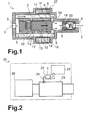
- Fig. 1 illustrates a delivery pump 1 which can deliver a fluid from a pump inlet 3 to a pump outlet 4 in a delivery direction 5.
- the delivery pump 1 has a delivery piston 2, which can be moved backwards and forwards in an axial bearing 6.
- the delivery piston 2 performs a delivery movement 11.
- the delivery piston 2 moves into and out of a delivery chamber 18 in a regular manner.
- the volume of the delivery chamber 18 is increased and reduced in a regular manner.
- the reduction in the volume is such that the minimum volume of the delivery chamber 18 which occurs during the delivery movement 11 is at least ten times, preferably twenty times, and particularly preferably one hundred times, less than the maximum volume of the delivery chamber 18 which occurs. Opening into the delivery chamber 18 is at least one chamber inlet opening 19, through which fluid can enter the delivery chamber 18 in the delivery direction 5.
- the delivery piston 2 is arranged close to a position of maximum retraction (that is to say in a direction towards the pump inlet 3) during the delivery movement 11 and, in this case, the volume of the delivery chamber 18 is close to the maximum volume described.
- the delivery piston 2 preferably passes over the at least one chamber inlet opening 19.
- the delivery piston 2 When the delivery piston 2 is covering the chamber inlet opening 19, no fluid can flow into the delivery chamber 18.
- the delivery piston 2 opens the delivery chamber 18, fluid can flow into the delivery chamber 18 through the chamber inlet opening 19.
- the delivery piston 2 pushes fluid out of the delivery chamber 18, through the nonreturn valve 20, towards the pump outlet 4.
- the nonreturn valve 20 prevents fluid from flowing back into the delivery chamber 18 from the pump outlet 4.
- the delivery movement 11 of the delivery piston 2 is achieved at least in part by means of a drive coil 27. An electric current can be passed through the drive coil 27.
- the drive coil 27 then exerts an electromagnetic force on the delivery piston 2, and the delivery piston 2 is moved.
- a spring (not shown here) can also be provided on the delivery piston 2, exerting on the delivery piston 2 a restoring force acting counter to a direction of action of the drive coil 27, for example.
- the axial bearing 6 of the delivery piston 2 is preferably embodied in the manner of a plain bearing.
- the axial bearing 6 is designed as a guide channel 8, in which the delivery piston 2 lies.
- the guide channel 8 has a guiding surface 14, and the delivery piston 2 has a piston surface 15.
- the guiding surface 14 and the piston surface 15 can slide upon one another, thus allowing the delivery piston 2 to perform the delivery movement 11 in the guide channel 8 or axial bearing 6.
- the axial bearing 6 has a cooling device 7.
- the cooling device 7 is designed to deliver the fluid delivered by the delivery pump 1 into the axial bearing 6 and especially into the gap 13 between the piston surface 15 and the guiding surface 14.
- the cooling device 7 is at least one passage 9, through which the fluid can enter the axial bearing 6 or guide channel 8 or gap 13.
- the passage 9 intersects the guide channel 8.
- the passage 9 opens into the axial bearing or guide channel 8 at an entry point 12.
- the passage 9 is designed as a bore, notch or slot in the wall of the guide channel 8, for example, and preferably forms a connection through which the fluid can pass into the axial bearing 6 or guide channel 8 or gap 13.
- At least one recess 10 is preferably provided in the delivery piston 2.
- the recess 10 is arranged in such a way that it passes over the entry point 12 of the passage 9 when the delivery piston 2 performs the delivery movement 11.
- the recess 10 thus promotes and intensifies the delivery of fluid into the axial bearing 6 or guide channel 8 or gap 13.
- a backflow 17 of fluid through the axial bearing 6 or guide channel 8 or gap 13 counter to the delivery direction 5 is preferably established.
- Fig. 2 shows a motor vehicle 25 having an internal combustion engine 26 and an exhaust gas treatment device 23 for cleaning the exhaust gases of the internal combustion engine 26.
- the reducing agent can be delivered from a tank 22 for a reducing agent into the exhaust gas treatment device 23 by means of a metering device 21.
- the metering device furthermore has a delivery line 24 from the tank 22 to the exhaust gas treatment device 23.
- a delivery pump 1 for delivering the reducing agent is provided in the delivery line 24.
Landscapes
- Engineering & Computer Science (AREA)
- Mechanical Engineering (AREA)
- General Engineering & Computer Science (AREA)
- Physics & Mathematics (AREA)
- Fluid Mechanics (AREA)
- Exhaust Gas After Treatment (AREA)
- Details Of Reciprocating Pumps (AREA)
- Reciprocating Pumps (AREA)
Abstract
Description
- The invention relates to a delivery pump for a fluid, which can be used in a metering device, for example, to meter a fluid from a tank into an exhaust gas treatment device for cleaning the exhaust gases from an internal combustion engine. Exhaust gas treatment devices in which a fluid is fed in for the purpose of cleaning the exhaust gases are widely used, especially in the motor vehicle sector.
- One exhaust gas cleaning method which is carried out particularly often in such exhaust gas treatment devices is that of selective catalytic reduction (SCR-method; SCR = selective catalytic reduction), in which nitrogen oxide compounds in the exhaust gas are reduced by means of a reducing agent. Ammonia is generally used as the reducing agent in this case. In motor vehicles, ammonia is normally stored not in the pure form but in the form of a precursor solution or precursor fluid, which can be converted into ammonia.
- Aqueous urea solution is used as the precursor solution, for example. A 32.5% aqueous urea solution, which can be obtained under the trade name AdBlue®, is used particularly often.
- This precursor solution can then be fed in to the exhaust gas in liquid form and then converted into ammonia in the exhaust gas by purely thermal means or by hydrolytic means with support from a hydrolysis catalyst. It is also possible for the precursor solution to be converted to ammonia outside the exhaust gas in a reactor provided for the purpose.
- To deliver the solution from a tank to the exhaust gas treatment device or to a reactor, a delivery pump is normally required. This delivery pump must make available the reducing agent to the exhaust gas treatment device during the entire period of operation of a motor vehicle. The delivery pump must therefore have a very long service life. Moreover, the delivery pump should be as inexpensive as possible.
- A delivery pump for reducing agent is known from German Patent
DE 10 2008 010 073 B4 , for example. - Taking the above as a starting point, it is the object of the present invention to further mitigate the technical problems described in connection with the prior art. In particular, the intention is to describe a further improved, particularly advantageous delivery pump for a fluid which is suitable especially for delivering reducing agent.
- These objects are achieved with a delivery pump in accordance with the features of
Patent Claim 1. Further advantageous embodiments of the delivery pump are indicated in the independently worded patent claims. The features presented individually in the patent claims can be combined in any technologically meaningful way and can be supplemented by explanatory material from the description, giving rise to additional variant embodiments of the invention. - The invention relates to a delivery pump for delivering a fluid, having a delivery piston, which can be moved in a delivery direction from a pump inlet to a pump outlet, wherein the delivery piston is supported in an axial bearing, and wherein the axial bearing has a cooling device, which is set up to cool the axial bearing with the fluid.
- The delivery pump is suitable especially for delivering reducing agent and, in particular, aqueous ammonia solution as a fluid.
- The delivery pump is preferably suitable for making available the fluid at a defined pressure at the pump outlet or for achieving a defined increase in the pressure of the fluid from the pump inlet to the pump outlet. For this purpose, a delivery pump drive can be controlled by a control unit, the control unit receiving information from at least one pressure sensor for the purpose of adjusting the defined pressure or the defined increase in pressure. The control unit can control the delivery pump drive on the basis of information from at least one pressure sensor. The delivery pump drive is preferably a drive coil. When an electric current flows through the drive coil, the drive coil produces an electromagnetic force which acts on the delivery piston of the delivery pump. The delivery piston can be set in motion by the force of the drive coil. The drive can also have a spring which can exert a restoring force on the delivery piston. By way of example, a drive coil can be set up to move the delivery piston towards the pump outlet in the delivery direction, counter to a spring, when a current flows through the drive coil. The spring can be set up to return the delivery piston towards the pump inlet, counter to the delivery direction, when no current is flowing through the drive coil and the drive coil is therefore not exerting any force on the delivery piston.
- The pump inlet is preferably designed for the connection of an intake line, via which the delivery pump can draw in fluid from a tank, for example. The pump outlet is preferably designed for the connection of a pressure line, into which the delivery pump can deliver fluid, e.g. towards an exhaust gas treatment device or towards an injector which opens into an exhaust gas treatment device. For the connection of the intake line and the pressure line, the pump inlet and the pump outlet preferably have corresponding connectors, to which the lines can be detachably connected. The delivery piston is preferably arranged on a common axis together with the pump inlet and the pump outlet.
- The axial bearing preferably allows movement of the delivery piston only in an axial direction extending along the delivery direction from the pump inlet to the pump outlet. Rotation or translational displacement of the delivery piston is preferably prevented by the axial bearing. The axial bearing is preferably a plain bearing. The delivery piston has a piston surface, and the axial bearing has a guiding surface. The piston surface and the guiding surface can slide upon one another.
- For details of the construction of such a delivery pump, reference may be made here especially to
German Patent DE 10 2008 010 073 B4 , which describes the construction thereof in detail inFig. 2 and in the explanations pertaining thereto in paragraphs [0039] to [0045]. SaidFig. 2 and the paragraphs mentioned are hereby incorporated in full by reference. - As the piston surface and the guiding surface slide upon one another in the axial bearing, heat is generated by friction. The cooling device is preferably set up to deliver the fluid into the axial bearing and preferably to the piston surface and the guiding surface in order to absorb and, where appropriate, carry away heat from the axial bearing. It has been found that high temperatures in the axial bearing of a delivery pump can drastically shorten the life of the delivery pump. This is the case especially when the delivery pump is used to deliver aqueous urea solution. At high temperatures, urea precipitates may form in the aqueous urea solution. These precipitates act like abrasive particles in the delivery pump and especially in a plain bearing and can damage the bearing and the delivery pump. It is therefore advantageous, especially for delivery pumps for delivering aqueous urea solution, to carry away the heat produced in a plain bearing. It is particularly advantageous for this purpose to use the fluid which is available in the delivery pump in any case.
- The delivery pump is particularly advantageous if the cooling device is simultaneously a lubricating device for lubricating the axial bearing with the fluid.
- An axial bearing which is embodied as a plain bearing is generally advantageous if a lubricant is provided. The lubricant reduces the friction between the surfaces in the plain bearing. In the delivery pumps considered here, the surfaces of the plain bearing are preferably a piston surface of the delivery piston and a guiding surface of a guide bore of the axial bearing in which the piston is guided. It is particularly preferred if a gap, in which a lubricating film consisting of the fluid is formed, is made between the piston surface and the guiding surface.
- By virtue of the fact that the fluid is simultaneously used as a coolant and a lubricant for the axial bearing of the delivery pump, it may be possible to dispense with an additional lubricant for the axial bearing.
- The delivery pump is particularly advantageous if the axial bearing is a guide channel, in which the delivery piston is supported in a sliding manner, and the cooling device is embodied as at least one passage, which intersects the guide channel and through which the fluid enters the guide channel at at least one entry point.
- The shape of the guide channel is preferably matched to a cross section of the delivery piston to enable the delivery piston to be moved backwards and forwards in the guide channel in a delivery movement. The passage can be a bore, a gap or a slot, for example, which meets the guide channel and thus intersects the guide channel.
- A plurality of passages is preferably arranged along the guide channel to enable the axial bearing or guide channel or guiding surface and the piston surface to be wetted as fully as possible with fluid. As another preferred option, a plurality of passages is also arranged around the delivery piston and the guiding channel in the circumferential direction to ensure complete wetting. For example, two to eight passages leading to the guide channel and distributed uniformly in the circumferential direction are in each case provided in two to six planes along the guide channel.
- The passages can be embodied as bores, gaps or the like, for example. The passages establish a connection through which the fluid can pass into the axial bearing or guide channel. This connection preferably extends through the delivery pump, starting from a channel, through which pump the fluid passes on the way from the pump inlet to the pump outlet or along which channel the fluid flows during normal delivery.
- The passages described are a technically particularly uncomplicated and effective solution for passing the fluid into the axial bearing.
- The delivery pump is particularly advantageous if the delivery piston has at least one recess in the region of the passage, said recess crossing the entry point of the passage during a delivery movement of the delivery piston in the axial bearing and, in the process, delivering the fluid into the axial bearing.
- The delivery piston preferably has a largely flat piston surface matched to the shape or guiding surface of the guide channel. Both the piston surface and the guiding surface preferably have a low roughness of, for example, less than 10 µm [micrometres] and preferably even less than 5 µm [micrometres]. The roughness of these surfaces is low in order to reduce the friction of the delivery piston in the guide channel of the axial bearing. The recess forms a re-entrant area of the delivery piston relative to the piston surface. The recess can be embodied as a single notch or opening in the delivery piston. It is also possible for the recess to form a complete network or complete system of channels on the piston surface, through which the fluid can pass, and thus allow distribution of the fluid over the piston surface and over the guiding surface. When the recess crosses the passage, an area of the recess and an area of the entry point of the passage overlap at least partially in an overlap zone. The fluid can then enter the recess from the passage. The delivery movement changes the area of the overlap zone because the entry point and the recess move relative to one another. During the delivery movement, there is preferably at least at times no overlap at all between the area of the entry point and the area of the recess. Indeed, the recess preferably crosses several different passages during the delivery movement. The fluid pressures prevailing at these different passages are preferably different. The fluid can thus be delivered effectively through the axial bearing via the recess.
- The use of at least one recess in the delivery piston for delivering the fluid into the axial bearing is particularly advantageous because the fluid is delivered effectively into the axial bearing and there is no need for any additional moving parts (such as an additional pump) for delivering the fluid into the axial bearing.
- The delivery pump is particularly advantageous if the axial bearing is embodied with a gap between a guiding surface of a guide channel of the axial bearing and a piston surface of the delivery piston, said gap having a gap width of at least 5 µm [micrometres].
- Such a gap width between the piston surface and the guiding surface is particularly advantageous in ensuring that a film of the fluid forms in the axial bearing or guide channel or gap, this film being particularly advantageous for cooling and, where appropriate, also for lubricating the axial bearing.
- The delivery pump is particularly advantageous if the axial bearing is set up in such a way that a backflow of fluid through the axial bearing counter to the delivery direction of the delivery pump is obtained.
- The backflow preferably covers the entire length of the axial bearing. In this way, particularly effective cooling of the axial bearing can be achieved. It also ensures that cooling of the axial bearing is uniformly distributed over the entire length of the axial bearing and also that no local overheating of the axial bearing occurs.
- The delivery pump is particularly advantageous if the delivery pump has a delivery chamber, at least one chamber inlet opening, which opens into the delivery chamber, and at least one nonreturn valve, which is arranged between the delivery chamber and the pump outlet in the delivery direction, wherein the delivery piston can perform a delivery movement into the delivery chamber and, in the process, pushes fluid present in the delivery chamber out through the nonreturn valve in the delivery direction to the pump outlet.
- During the delivery movement, the delivery piston moves into and out of said delivery chamber in a regular manner. During the delivery movement of the delivery piston, the volume of the delivery chamber is thus increased and reduced in a regular manner. In a particularly advantageous variant of the delivery pump, the reduction in the volume is such that the minimum volume of the delivery chamber which occurs during the delivery movement is at least ten times, preferably twenty times, and particularly preferably one hundred times, less than the maximum volume of the delivery chamber which occurs. Opening into the delivery chamber is at least one chamber inlet opening, through which fluid can enter the delivery chamber in the delivery direction. If a plurality of chamber inlet openings is provided, they are preferably all located in a common plane aligned perpendicularly to the direction of movement or to the axis of movement of the delivery piston. This is possible particularly if the delivery piston is arranged close to a position of maximum retraction (that is to say in a direction towards the pump inlet) during the delivery movement and, in this case, the volume of the delivery chamber is close to the maximum volume described. During the delivery movement, the delivery piston preferably passes over the at least one chamber inlet opening. When the delivery piston is covering the chamber inlet opening, no fluid can flow into the delivery chamber. When the delivery piston opens the delivery chamber, fluid can flow into the delivery chamber through the chamber inlet opening. There is a nonreturn valve between the delivery chamber and the pump outlet in the delivery direction. During a part of the delivery movement in the direction towards the pump outlet, the delivery piston pushes fluid out of the delivery chamber, through the nonreturn valve, towards the pump outlet. The nonreturn valve prevents fluid from flowing back into the delivery chamber from the pump outlet.
- With a delivery pump constructed in this way, it is also possible to achieve a delivery pump with a relatively high metering accuracy. The delivery pump can then be used not only as a simple delivery pump but also as a metering pump. In the case of a metering pump, the quantity of fluid delivered by the delivery pump can be determined precisely. In the case of the delivery pump described here, the quantity of fluid delivered is obtained from the number of delivery strokes of the delivery piston and the delivery chamber volume which the delivery chamber has when the delivery piston is just covering the chamber inlet openings. The delivery quantity can be calculated as the product of this volume and the number of delivery strokes.
- For details of the construction of a delivery chamber of a delivery pump, reference may be made here once again especially to
German Patent DE 10 2008 010 073 B4 , which describes the construction of a delivery chamber in detail inFig. 2 and in the explanations pertaining thereto in paragraphs [0039] to [0045]. SaidFig. 2 and the paragraphs mentioned are incorporated here in full by reference. - The scope of the invention also includes a metering device for delivering a reducing agent from a tank into an exhaust gas treatment device, wherein the metering device has a delivery line from the tank to the exhaust gas treatment device and a delivery pump according to the invention, wherein the delivery pump is arranged in the delivery line in order to deliver reducing agent as a fluid from the tank to the exhaust gas treatment device.
- The delivery pump described, as explained above, is particularly advantageous for delivering reducing agent. It is therefore particularly advantageous to employ the delivery pump described in a metering device for reducing agent.
- The scope of the invention also includes a motor vehicle having an internal combustion engine, an exhaust gas treatment device for cleaning the exhaust gases from the internal combustion engine and a metering device according to the invention, which is set up for metering reducing agent into the exhaust gas treatment device.
- The invention and the associated technology are explained in greater detail below with reference to the figures. The figures show particularly preferred embodiments, but the invention is not restricted thereto. In particular, it should be noted that the figures and, in particular, the proportions illustrated are only schematic. In the drawings is shown:
- Fig. 1
- a variant embodiment of a delivery pump, and
- Fig. 2
- a motor vehicle having a metering device with a delivery pump.
-
Fig. 1 illustrates adelivery pump 1 which can deliver a fluid from apump inlet 3 to a pump outlet 4 in adelivery direction 5. For delivery, thedelivery pump 1 has a delivery piston 2, which can be moved backwards and forwards in an axial bearing 6. During this movement in the axial bearing 6, the delivery piston 2 performs adelivery movement 11. During thedelivery movement 11, the delivery piston 2 moves into and out of adelivery chamber 18 in a regular manner. During thedelivery movement 11 of the delivery piston 2, the volume of thedelivery chamber 18 is increased and reduced in a regular manner. In a particularly advantageous variant of thedelivery pump 1, the reduction in the volume is such that the minimum volume of thedelivery chamber 18 which occurs during thedelivery movement 11 is at least ten times, preferably twenty times, and particularly preferably one hundred times, less than the maximum volume of thedelivery chamber 18 which occurs. Opening into thedelivery chamber 18 is at least one chamber inlet opening 19, through which fluid can enter thedelivery chamber 18 in thedelivery direction 5. This is possible particularly if the delivery piston 2 is arranged close to a position of maximum retraction (that is to say in a direction towards the pump inlet 3) during thedelivery movement 11 and, in this case, the volume of thedelivery chamber 18 is close to the maximum volume described. During thedelivery movement 11, the delivery piston 2 preferably passes over the at least onechamber inlet opening 19. When the delivery piston 2 is covering the chamber inlet opening 19, no fluid can flow into thedelivery chamber 18. When the delivery piston 2 opens thedelivery chamber 18, fluid can flow into thedelivery chamber 18 through thechamber inlet opening 19. There is anonreturn valve 20 between thedelivery chamber 18 and the pump outlet 4 in thedelivery direction 5. During a part of thedelivery movement 11 in the direction towards the pump outlet 4, the delivery piston 2 pushes fluid out of thedelivery chamber 18, through thenonreturn valve 20, towards the pump outlet 4. Thenonreturn valve 20 prevents fluid from flowing back into thedelivery chamber 18 from the pump outlet 4. Thedelivery movement 11 of the delivery piston 2 is achieved at least in part by means of adrive coil 27. An electric current can be passed through thedrive coil 27. Thedrive coil 27 then exerts an electromagnetic force on the delivery piston 2, and the delivery piston 2 is moved. In addition, a spring (not shown here) can also be provided on the delivery piston 2, exerting on the delivery piston 2 a restoring force acting counter to a direction of action of thedrive coil 27, for example. - The axial bearing 6 of the delivery piston 2 is preferably embodied in the manner of a plain bearing. The axial bearing 6 is designed as a guide channel 8, in which the delivery piston 2 lies. The guide channel 8 has a guiding
surface 14, and the delivery piston 2 has apiston surface 15. The guidingsurface 14 and thepiston surface 15 can slide upon one another, thus allowing the delivery piston 2 to perform thedelivery movement 11 in the guide channel 8 or axial bearing 6. There is preferably agap 13 between thepiston surface 15 and the guidingsurface 14, said gap having agap width 16 of at least 5 µm [micrometres], for example, to enable thepiston surface 15 to slide easily on the guidingsurface 14. - The axial bearing 6 has a cooling device 7. The cooling device 7 is designed to deliver the fluid delivered by the
delivery pump 1 into the axial bearing 6 and especially into thegap 13 between thepiston surface 15 and the guidingsurface 14. In the variant embodiment illustrated here, the cooling device 7 is at least one passage 9, through which the fluid can enter the axial bearing 6 or guide channel 8 orgap 13. For this purpose, the passage 9 intersects the guide channel 8. The passage 9 opens into the axial bearing or guide channel 8 at anentry point 12. The passage 9 is designed as a bore, notch or slot in the wall of the guide channel 8, for example, and preferably forms a connection through which the fluid can pass into the axial bearing 6 or guide channel 8 orgap 13. - At least one
recess 10 is preferably provided in the delivery piston 2. Therecess 10 is arranged in such a way that it passes over theentry point 12 of the passage 9 when the delivery piston 2 performs thedelivery movement 11. Therecess 10 thus promotes and intensifies the delivery of fluid into the axial bearing 6 or guide channel 8 orgap 13. Abackflow 17 of fluid through the axial bearing 6 or guide channel 8 orgap 13 counter to thedelivery direction 5 is preferably established. -
Fig. 2 shows amotor vehicle 25 having aninternal combustion engine 26 and an exhaustgas treatment device 23 for cleaning the exhaust gases of theinternal combustion engine 26. The reducing agent can be delivered from atank 22 for a reducing agent into the exhaustgas treatment device 23 by means of ametering device 21. The metering device furthermore has adelivery line 24 from thetank 22 to the exhaustgas treatment device 23. Adelivery pump 1 for delivering the reducing agent is provided in thedelivery line 24. -
- 1
- delivery pump
- 2
- delivery piston
- 3
- pump inlet
- 4
- pump outlet
- 5
- delivery direction
- 6
- axial bearing
- 7
- cooling device
- 8
- guide channel
- 9
- passage
- 10
- recess
- 11
- delivery movement
- 12
- entry point
- 13
- gap
- 14
- guiding surface
- 15
- piston surface
- 16
- gap width
- 17
- backflow
- 18
- delivery chamber
- 19
- chamber inlet opening
- 20
- nonreturn valve
- 21
- metering device
- 22
- tank
- 23
- exhaust gas treatment device
- 24
- delivery line
- 2 5
- motor vehicle
- 26
- internal combustion engine
- 27
- drive coil
Claims (9)
- Delivery pump (1) for delivering a fluid, having a delivery piston (2), which can be moved in a delivery direction (5) from a pump inlet (3) to a pump outlet (4), wherein the delivery piston (2) is supported in an axial bearing (6), and wherein the axial bearing (6) has a cooling device (7), which is set up to cool the axial bearing (6) with the fluid.
- Delivery pump (1) according to one of the preceding patent claims, wherein the cooling device (7) is simultaneously a lubricating device for lubricating the axial bearing (6) with the fluid.
- Delivery pump (1) according to one of the preceding patent claims, wherein the axial bearing (6) is a guide channel (8), in which the delivery piston (2) is supported in a sliding manner, and the cooling device (7) is embodied as at least one passage (9), which intersects the guide channel (8) and through which the fluid enters the guide channel (8) at at least one entry point (12).
- Delivery pump (1) according to Patent Claim 3, wherein the delivery piston (2) has at least one recess (10) in the region of the passage (9), said recess crossing the entry point (12) of the passage (9) during a delivery movement (11) of the delivery piston (2) in the axial bearing (6) and, in the process, delivering the fluid into the axial bearing (6).
- Delivery pump (1) according to one of the preceding patent claims, wherein the axial bearing (6) is embodied with a gap (13) between a guiding surface (14) of a guide channel (8) of the axial bearing (6) and a piston surface (15) of the delivery piston (2), said gap having a gap width (16) of at least 5 µm [micrometres].
- Delivery pump (1) according to one of the preceding patent claims, wherein the axial bearing (6) is set up in such a way that a backflow (17) of fluid through the axial bearing (6) counter to the delivery direction (5) of the delivery pump (1) is obtained.
- Delivery pump (1) according to one of the preceding patent claims, wherein the delivery pump (1) has a delivery chamber (18), at least one chamber inlet opening (19), which opens into the delivery chamber (18), and at least one nonreturn valve (20), which is arranged between the delivery chamber (18) and the pump outlet (4) in the delivery direction (5), wherein the delivery piston (2) can perform a delivery movement (11) into the delivery chamber (18) and, in the process, pushes fluid present in the delivery chamber (18) out through the nonreturn valve (20) in the delivery direction (5) to the pump outlet (4).
- Metering device (21) for delivering a reducing agent from a tank (22) into an exhaust gas treatment device (23), wherein the metering device (21) has a delivery line (24) from the tank (22) to the exhaust gas treatment device (23) and a delivery pump (1) according to one of the preceding patent claims, wherein the delivery pump (1) is arranged in the delivery line (24) in order to deliver reducing agent as a fluid from the tank (22) to the exhaust gas treatment device (23).
- Motor vehicle (25) having an internal combustion engine (26) and an exhaust gas treatment device (23) for cleaning the exhaust gases from the internal combustion engine (26) and a metering device (21) according to Patent Claim 8, which is set up for metering reducing agent into the exhaust gas treatment device (23).
Priority Applications (1)
| Application Number | Priority Date | Filing Date | Title |
|---|---|---|---|
| EP12188656.8A EP2584198A3 (en) | 2011-10-21 | 2012-10-16 | Delivery pump for a fluid |
Applications Claiming Priority (2)
| Application Number | Priority Date | Filing Date | Title |
|---|---|---|---|
| EP11290490 | 2011-10-21 | ||
| EP12188656.8A EP2584198A3 (en) | 2011-10-21 | 2012-10-16 | Delivery pump for a fluid |
Publications (2)
| Publication Number | Publication Date |
|---|---|
| EP2584198A2 true EP2584198A2 (en) | 2013-04-24 |
| EP2584198A3 EP2584198A3 (en) | 2016-03-30 |
Family
ID=47022573
Family Applications (1)
| Application Number | Title | Priority Date | Filing Date |
|---|---|---|---|
| EP12188656.8A Withdrawn EP2584198A3 (en) | 2011-10-21 | 2012-10-16 | Delivery pump for a fluid |
Country Status (3)
| Country | Link |
|---|---|
| US (1) | US20130098005A1 (en) |
| EP (1) | EP2584198A3 (en) |
| JP (1) | JP2013087776A (en) |
Cited By (4)
| Publication number | Priority date | Publication date | Assignee | Title |
|---|---|---|---|---|
| WO2014202260A1 (en) * | 2013-06-20 | 2014-12-24 | Robert Bosch Gmbh | Injection device |
| WO2015169476A1 (en) * | 2014-05-08 | 2015-11-12 | Robert Bosch Gmbh | Fuel pump |
| CN107035585A (en) * | 2015-11-10 | 2017-08-11 | 罗伯特·博世有限公司 | Fuel pump with outlet valve in piston and fuel path of flushing actuator |
| CN108343589A (en) * | 2016-07-21 | 2018-07-31 | 陕西仙童科技有限公司 | A kind of novel piston component, compression unit and oil-free lubrication Linearkompressor |
Families Citing this family (1)
| Publication number | Priority date | Publication date | Assignee | Title |
|---|---|---|---|---|
| WO2015100140A1 (en) * | 2013-12-27 | 2015-07-02 | The Coca-Cola Company | Pumping and metering a viscous micro-ingredient using a volumetric metering device |
Citations (1)
| Publication number | Priority date | Publication date | Assignee | Title |
|---|---|---|---|---|
| DE102008010073B4 (en) | 2008-02-19 | 2010-10-21 | Thomas Magnete Gmbh | System and method for metering a fluid |
Family Cites Families (9)
| Publication number | Priority date | Publication date | Assignee | Title |
|---|---|---|---|---|
| GB848422A (en) * | 1956-03-03 | 1960-09-14 | Orange G M B H L | Improvements in or relating to fuel-injection units for internal-combustion engines |
| JPS54133608A (en) * | 1978-04-08 | 1979-10-17 | Iwaki Co Ltd | Electromagnetic drive type reciprocating pumping plant |
| JPH10220343A (en) * | 1997-02-04 | 1998-08-18 | Komatsu Ltd | Piston pump / motor |
| WO2002040886A1 (en) * | 2000-11-17 | 2002-05-23 | Mannesmann Sachs Ag | Clutch system |
| ATE512300T1 (en) * | 2006-07-12 | 2011-06-15 | Delphi Tech Holding Sarl | DOSING PUMP FOR A REDUCING AGENT |
| JP4625789B2 (en) * | 2006-07-20 | 2011-02-02 | 日立オートモティブシステムズ株式会社 | High pressure fuel pump |
| JP2009115032A (en) * | 2007-11-08 | 2009-05-28 | Nippon Soken Inc | Exhaust gas purification device for internal combustion engine |
| US8225602B2 (en) * | 2009-06-11 | 2012-07-24 | Stanadyne Corporation | Integrated pump and injector for exhaust after treatment |
| EP2375054B1 (en) * | 2010-04-06 | 2013-06-19 | Delphi Technologies Holding S.à.r.l. | Reagent dosing system and pump |
-
2012
- 2012-10-16 EP EP12188656.8A patent/EP2584198A3/en not_active Withdrawn
- 2012-10-19 JP JP2012231512A patent/JP2013087776A/en active Pending
- 2012-10-22 US US13/656,879 patent/US20130098005A1/en not_active Abandoned
Patent Citations (1)
| Publication number | Priority date | Publication date | Assignee | Title |
|---|---|---|---|---|
| DE102008010073B4 (en) | 2008-02-19 | 2010-10-21 | Thomas Magnete Gmbh | System and method for metering a fluid |
Cited By (5)
| Publication number | Priority date | Publication date | Assignee | Title |
|---|---|---|---|---|
| WO2014202260A1 (en) * | 2013-06-20 | 2014-12-24 | Robert Bosch Gmbh | Injection device |
| WO2015169476A1 (en) * | 2014-05-08 | 2015-11-12 | Robert Bosch Gmbh | Fuel pump |
| CN106460742A (en) * | 2014-05-08 | 2017-02-22 | 罗伯特·博世有限公司 | Fuel pump |
| CN107035585A (en) * | 2015-11-10 | 2017-08-11 | 罗伯特·博世有限公司 | Fuel pump with outlet valve in piston and fuel path of flushing actuator |
| CN108343589A (en) * | 2016-07-21 | 2018-07-31 | 陕西仙童科技有限公司 | A kind of novel piston component, compression unit and oil-free lubrication Linearkompressor |
Also Published As
| Publication number | Publication date |
|---|---|
| US20130098005A1 (en) | 2013-04-25 |
| JP2013087776A (en) | 2013-05-13 |
| EP2584198A3 (en) | 2016-03-30 |
Similar Documents
| Publication | Publication Date | Title |
|---|---|---|
| EP2584198A2 (en) | Delivery pump for a fluid | |
| CN103502596B (en) | Pressure swirl flow injector with reduced flow variability and return flow | |
| EP1192337B1 (en) | Valve seat device for a metering valve of an exhaust treatment station | |
| EP2627881B1 (en) | Arrangement for introducing a liquid medium into exhaust gases from a combustion engine | |
| JP4095553B2 (en) | Reductant pump for exhaust gas aftertreatment device of internal combustion engine | |
| CN105308280B (en) | Method for operating a device for metering a liquid | |
| JP5789336B2 (en) | Pump assembly for dispensing reactants | |
| EP2758644B1 (en) | Heat exchanger for a metering unit of an scr exhaust-gas aftertreatment device | |
| JP2014530990A (en) | Distribution module | |
| US20090217650A1 (en) | Device for introducing a liquid substance into the exhaust gas of an internal combustion engine | |
| CN103764964A (en) | Electromagnetically controlled injector having flux bridge and flux break | |
| CN107299851B (en) | Integrated device, exhaust gas aftertreatment system and control method | |
| US20220056831A1 (en) | Systems and methods for mixing exhaust gas and reductant | |
| WO2012107484A1 (en) | Injector for a urea-water solution | |
| RU2601776C2 (en) | Conveying unit for reducing agent | |
| EP2823880B1 (en) | Exhaust gas purification apparatus for an internal combustion engine | |
| US9835154B2 (en) | Pump for metering a liquid additive for a selective catalytic reduction device | |
| EP2831386B1 (en) | Delivery unit for a liquid additive with a termperature sensor | |
| CN105492770A (en) | Pump for delivering a liquid | |
| WO2015188329A1 (en) | Fluid delivery system with line pressure control valve | |
| KR20160147848A (en) | Pump for conveying a fluid | |
| US10385849B2 (en) | Method for operating a pump | |
| HK1208519A1 (en) | Scr module | |
| CN207470268U (en) | Integrating device and its exhaust gas aftertreatment system | |
| CN207598324U (en) | Integrating device and its exhaust gas aftertreatment system |
Legal Events
| Date | Code | Title | Description |
|---|---|---|---|
| PUAI | Public reference made under article 153(3) epc to a published international application that has entered the european phase |
Free format text: ORIGINAL CODE: 0009012 |
|
| AK | Designated contracting states |
Kind code of ref document: A2 Designated state(s): AL AT BE BG CH CY CZ DE DK EE ES FI FR GB GR HR HU IE IS IT LI LT LU LV MC MK MT NL NO PL PT RO RS SE SI SK SM TR |
|
| AX | Request for extension of the european patent |
Extension state: BA ME |
|
| PUAL | Search report despatched |
Free format text: ORIGINAL CODE: 0009013 |
|
| RAP1 | Party data changed (applicant data changed or rights of an application transferred) |
Owner name: CONTINENTAL AUTOMOTIVE GMBH |
|
| AK | Designated contracting states |
Kind code of ref document: A3 Designated state(s): AL AT BE BG CH CY CZ DE DK EE ES FI FR GB GR HR HU IE IS IT LI LT LU LV MC MK MT NL NO PL PT RO RS SE SI SK SM TR |
|
| AX | Request for extension of the european patent |
Extension state: BA ME |
|
| RIC1 | Information provided on ipc code assigned before grant |
Ipc: F04B 53/08 20060101ALI20160224BHEP Ipc: F04B 17/04 20060101AFI20160224BHEP Ipc: F04B 35/04 20060101ALI20160224BHEP |
|
| 17P | Request for examination filed |
Effective date: 20160930 |
|
| RBV | Designated contracting states (corrected) |
Designated state(s): AL AT BE BG CH CY CZ DE DK EE ES FI FR GB GR HR HU IE IS IT LI LT LU LV MC MK MT NL NO PL PT RO RS SE SI SK SM TR |
|
| STAA | Information on the status of an ep patent application or granted ep patent |
Free format text: STATUS: THE APPLICATION IS DEEMED TO BE WITHDRAWN |
|
| 18D | Application deemed to be withdrawn |
Effective date: 20180501 |