EP2583860A2 - System, charging device, and method of charging power storage device - Google Patents
System, charging device, and method of charging power storage device Download PDFInfo
- Publication number
- EP2583860A2 EP2583860A2 EP12189030.5A EP12189030A EP2583860A2 EP 2583860 A2 EP2583860 A2 EP 2583860A2 EP 12189030 A EP12189030 A EP 12189030A EP 2583860 A2 EP2583860 A2 EP 2583860A2
- Authority
- EP
- European Patent Office
- Prior art keywords
- charging
- charging device
- current
- network
- power storage
- Prior art date
- Legal status (The legal status is an assumption and is not a legal conclusion. Google has not performed a legal analysis and makes no representation as to the accuracy of the status listed.)
- Granted
Links
- 238000000034 method Methods 0.000 title claims description 38
- 230000004044 response Effects 0.000 claims description 3
- 230000006870 function Effects 0.000 description 25
- 238000010586 diagram Methods 0.000 description 14
- 230000005611 electricity Effects 0.000 description 10
- 239000004020 conductor Substances 0.000 description 5
- 238000003491 array Methods 0.000 description 2
- 238000013475 authorization Methods 0.000 description 2
- 239000000446 fuel Substances 0.000 description 2
- 230000002250 progressing effect Effects 0.000 description 2
- 239000007787 solid Substances 0.000 description 2
- 230000005540 biological transmission Effects 0.000 description 1
- 239000004973 liquid crystal related substance Substances 0.000 description 1
- 230000000750 progressive effect Effects 0.000 description 1
- 230000036962 time dependent Effects 0.000 description 1
- 230000000007 visual effect Effects 0.000 description 1
Images


Classifications
-
- H—ELECTRICITY
- H02—GENERATION; CONVERSION OR DISTRIBUTION OF ELECTRIC POWER
- H02J—CIRCUIT ARRANGEMENTS OR SYSTEMS FOR SUPPLYING OR DISTRIBUTING ELECTRIC POWER; SYSTEMS FOR STORING ELECTRIC ENERGY
- H02J7/00—Circuit arrangements for charging or depolarising batteries or for supplying loads from batteries
- H02J7/0013—Circuit arrangements for charging or depolarising batteries or for supplying loads from batteries acting upon several batteries simultaneously or sequentially
-
- B—PERFORMING OPERATIONS; TRANSPORTING
- B60—VEHICLES IN GENERAL
- B60L—PROPULSION OF ELECTRICALLY-PROPELLED VEHICLES; SUPPLYING ELECTRIC POWER FOR AUXILIARY EQUIPMENT OF ELECTRICALLY-PROPELLED VEHICLES; ELECTRODYNAMIC BRAKE SYSTEMS FOR VEHICLES IN GENERAL; MAGNETIC SUSPENSION OR LEVITATION FOR VEHICLES; MONITORING OPERATING VARIABLES OF ELECTRICALLY-PROPELLED VEHICLES; ELECTRIC SAFETY DEVICES FOR ELECTRICALLY-PROPELLED VEHICLES
- B60L53/00—Methods of charging batteries, specially adapted for electric vehicles; Charging stations or on-board charging equipment therefor; Exchange of energy storage elements in electric vehicles
- B60L53/60—Monitoring or controlling charging stations
- B60L53/63—Monitoring or controlling charging stations in response to network capacity
-
- B—PERFORMING OPERATIONS; TRANSPORTING
- B60—VEHICLES IN GENERAL
- B60L—PROPULSION OF ELECTRICALLY-PROPELLED VEHICLES; SUPPLYING ELECTRIC POWER FOR AUXILIARY EQUIPMENT OF ELECTRICALLY-PROPELLED VEHICLES; ELECTRODYNAMIC BRAKE SYSTEMS FOR VEHICLES IN GENERAL; MAGNETIC SUSPENSION OR LEVITATION FOR VEHICLES; MONITORING OPERATING VARIABLES OF ELECTRICALLY-PROPELLED VEHICLES; ELECTRIC SAFETY DEVICES FOR ELECTRICALLY-PROPELLED VEHICLES
- B60L50/00—Electric propulsion with power supplied within the vehicle
- B60L50/50—Electric propulsion with power supplied within the vehicle using propulsion power supplied by batteries or fuel cells
-
- B—PERFORMING OPERATIONS; TRANSPORTING
- B60—VEHICLES IN GENERAL
- B60L—PROPULSION OF ELECTRICALLY-PROPELLED VEHICLES; SUPPLYING ELECTRIC POWER FOR AUXILIARY EQUIPMENT OF ELECTRICALLY-PROPELLED VEHICLES; ELECTRODYNAMIC BRAKE SYSTEMS FOR VEHICLES IN GENERAL; MAGNETIC SUSPENSION OR LEVITATION FOR VEHICLES; MONITORING OPERATING VARIABLES OF ELECTRICALLY-PROPELLED VEHICLES; ELECTRIC SAFETY DEVICES FOR ELECTRICALLY-PROPELLED VEHICLES
- B60L53/00—Methods of charging batteries, specially adapted for electric vehicles; Charging stations or on-board charging equipment therefor; Exchange of energy storage elements in electric vehicles
- B60L53/60—Monitoring or controlling charging stations
- B60L53/62—Monitoring or controlling charging stations in response to charging parameters, e.g. current, voltage or electrical charge
-
- B—PERFORMING OPERATIONS; TRANSPORTING
- B60—VEHICLES IN GENERAL
- B60L—PROPULSION OF ELECTRICALLY-PROPELLED VEHICLES; SUPPLYING ELECTRIC POWER FOR AUXILIARY EQUIPMENT OF ELECTRICALLY-PROPELLED VEHICLES; ELECTRODYNAMIC BRAKE SYSTEMS FOR VEHICLES IN GENERAL; MAGNETIC SUSPENSION OR LEVITATION FOR VEHICLES; MONITORING OPERATING VARIABLES OF ELECTRICALLY-PROPELLED VEHICLES; ELECTRIC SAFETY DEVICES FOR ELECTRICALLY-PROPELLED VEHICLES
- B60L53/00—Methods of charging batteries, specially adapted for electric vehicles; Charging stations or on-board charging equipment therefor; Exchange of energy storage elements in electric vehicles
- B60L53/60—Monitoring or controlling charging stations
- B60L53/66—Data transfer between charging stations and vehicles
-
- B—PERFORMING OPERATIONS; TRANSPORTING
- B60—VEHICLES IN GENERAL
- B60L—PROPULSION OF ELECTRICALLY-PROPELLED VEHICLES; SUPPLYING ELECTRIC POWER FOR AUXILIARY EQUIPMENT OF ELECTRICALLY-PROPELLED VEHICLES; ELECTRODYNAMIC BRAKE SYSTEMS FOR VEHICLES IN GENERAL; MAGNETIC SUSPENSION OR LEVITATION FOR VEHICLES; MONITORING OPERATING VARIABLES OF ELECTRICALLY-PROPELLED VEHICLES; ELECTRIC SAFETY DEVICES FOR ELECTRICALLY-PROPELLED VEHICLES
- B60L53/00—Methods of charging batteries, specially adapted for electric vehicles; Charging stations or on-board charging equipment therefor; Exchange of energy storage elements in electric vehicles
- B60L53/60—Monitoring or controlling charging stations
- B60L53/67—Controlling two or more charging stations
-
- H—ELECTRICITY
- H01—ELECTRIC ELEMENTS
- H01M—PROCESSES OR MEANS, e.g. BATTERIES, FOR THE DIRECT CONVERSION OF CHEMICAL ENERGY INTO ELECTRICAL ENERGY
- H01M10/00—Secondary cells; Manufacture thereof
- H01M10/42—Methods or arrangements for servicing or maintenance of secondary cells or secondary half-cells
- H01M10/46—Accumulators structurally combined with charging apparatus
-
- H—ELECTRICITY
- H02—GENERATION; CONVERSION OR DISTRIBUTION OF ELECTRIC POWER
- H02J—CIRCUIT ARRANGEMENTS OR SYSTEMS FOR SUPPLYING OR DISTRIBUTING ELECTRIC POWER; SYSTEMS FOR STORING ELECTRIC ENERGY
- H02J3/00—Circuit arrangements for ac mains or ac distribution networks
- H02J3/28—Arrangements for balancing of the load in a network by storage of energy
- H02J3/32—Arrangements for balancing of the load in a network by storage of energy using batteries with converting means
- H02J3/322—Arrangements for balancing of the load in a network by storage of energy using batteries with converting means the battery being on-board an electric or hybrid vehicle, e.g. vehicle to grid arrangements [V2G], power aggregation, use of the battery for network load balancing, coordinated or cooperative battery charging
-
- H02J7/0027—
-
- H—ELECTRICITY
- H02—GENERATION; CONVERSION OR DISTRIBUTION OF ELECTRIC POWER
- H02J—CIRCUIT ARRANGEMENTS OR SYSTEMS FOR SUPPLYING OR DISTRIBUTING ELECTRIC POWER; SYSTEMS FOR STORING ELECTRIC ENERGY
- H02J7/00—Circuit arrangements for charging or depolarising batteries or for supplying loads from batteries
- H02J7/007—Regulation of charging or discharging current or voltage
-
- H—ELECTRICITY
- H02—GENERATION; CONVERSION OR DISTRIBUTION OF ELECTRIC POWER
- H02J—CIRCUIT ARRANGEMENTS OR SYSTEMS FOR SUPPLYING OR DISTRIBUTING ELECTRIC POWER; SYSTEMS FOR STORING ELECTRIC ENERGY
- H02J7/00—Circuit arrangements for charging or depolarising batteries or for supplying loads from batteries
- H02J7/02—Circuit arrangements for charging or depolarising batteries or for supplying loads from batteries for charging batteries from ac mains by converters
- H02J7/04—Regulation of charging current or voltage
-
- H—ELECTRICITY
- H02—GENERATION; CONVERSION OR DISTRIBUTION OF ELECTRIC POWER
- H02J—CIRCUIT ARRANGEMENTS OR SYSTEMS FOR SUPPLYING OR DISTRIBUTING ELECTRIC POWER; SYSTEMS FOR STORING ELECTRIC ENERGY
- H02J2310/00—The network for supplying or distributing electric power characterised by its spatial reach or by the load
- H02J2310/40—The network being an on-board power network, i.e. within a vehicle
- H02J2310/48—The network being an on-board power network, i.e. within a vehicle for electric vehicles [EV] or hybrid vehicles [HEV]
-
- Y—GENERAL TAGGING OF NEW TECHNOLOGICAL DEVELOPMENTS; GENERAL TAGGING OF CROSS-SECTIONAL TECHNOLOGIES SPANNING OVER SEVERAL SECTIONS OF THE IPC; TECHNICAL SUBJECTS COVERED BY FORMER USPC CROSS-REFERENCE ART COLLECTIONS [XRACs] AND DIGESTS
- Y02—TECHNOLOGIES OR APPLICATIONS FOR MITIGATION OR ADAPTATION AGAINST CLIMATE CHANGE
- Y02E—REDUCTION OF GREENHOUSE GAS [GHG] EMISSIONS, RELATED TO ENERGY GENERATION, TRANSMISSION OR DISTRIBUTION
- Y02E60/00—Enabling technologies; Technologies with a potential or indirect contribution to GHG emissions mitigation
- Y02E60/10—Energy storage using batteries
-
- Y—GENERAL TAGGING OF NEW TECHNOLOGICAL DEVELOPMENTS; GENERAL TAGGING OF CROSS-SECTIONAL TECHNOLOGIES SPANNING OVER SEVERAL SECTIONS OF THE IPC; TECHNICAL SUBJECTS COVERED BY FORMER USPC CROSS-REFERENCE ART COLLECTIONS [XRACs] AND DIGESTS
- Y02—TECHNOLOGIES OR APPLICATIONS FOR MITIGATION OR ADAPTATION AGAINST CLIMATE CHANGE
- Y02T—CLIMATE CHANGE MITIGATION TECHNOLOGIES RELATED TO TRANSPORTATION
- Y02T10/00—Road transport of goods or passengers
- Y02T10/60—Other road transportation technologies with climate change mitigation effect
- Y02T10/70—Energy storage systems for electromobility, e.g. batteries
-
- Y—GENERAL TAGGING OF NEW TECHNOLOGICAL DEVELOPMENTS; GENERAL TAGGING OF CROSS-SECTIONAL TECHNOLOGIES SPANNING OVER SEVERAL SECTIONS OF THE IPC; TECHNICAL SUBJECTS COVERED BY FORMER USPC CROSS-REFERENCE ART COLLECTIONS [XRACs] AND DIGESTS
- Y02—TECHNOLOGIES OR APPLICATIONS FOR MITIGATION OR ADAPTATION AGAINST CLIMATE CHANGE
- Y02T—CLIMATE CHANGE MITIGATION TECHNOLOGIES RELATED TO TRANSPORTATION
- Y02T10/00—Road transport of goods or passengers
- Y02T10/60—Other road transportation technologies with climate change mitigation effect
- Y02T10/7072—Electromobility specific charging systems or methods for batteries, ultracapacitors, supercapacitors or double-layer capacitors
-
- Y—GENERAL TAGGING OF NEW TECHNOLOGICAL DEVELOPMENTS; GENERAL TAGGING OF CROSS-SECTIONAL TECHNOLOGIES SPANNING OVER SEVERAL SECTIONS OF THE IPC; TECHNICAL SUBJECTS COVERED BY FORMER USPC CROSS-REFERENCE ART COLLECTIONS [XRACs] AND DIGESTS
- Y02—TECHNOLOGIES OR APPLICATIONS FOR MITIGATION OR ADAPTATION AGAINST CLIMATE CHANGE
- Y02T—CLIMATE CHANGE MITIGATION TECHNOLOGIES RELATED TO TRANSPORTATION
- Y02T90/00—Enabling technologies or technologies with a potential or indirect contribution to GHG emissions mitigation
- Y02T90/10—Technologies relating to charging of electric vehicles
- Y02T90/12—Electric charging stations
-
- Y—GENERAL TAGGING OF NEW TECHNOLOGICAL DEVELOPMENTS; GENERAL TAGGING OF CROSS-SECTIONAL TECHNOLOGIES SPANNING OVER SEVERAL SECTIONS OF THE IPC; TECHNICAL SUBJECTS COVERED BY FORMER USPC CROSS-REFERENCE ART COLLECTIONS [XRACs] AND DIGESTS
- Y02—TECHNOLOGIES OR APPLICATIONS FOR MITIGATION OR ADAPTATION AGAINST CLIMATE CHANGE
- Y02T—CLIMATE CHANGE MITIGATION TECHNOLOGIES RELATED TO TRANSPORTATION
- Y02T90/00—Enabling technologies or technologies with a potential or indirect contribution to GHG emissions mitigation
- Y02T90/10—Technologies relating to charging of electric vehicles
- Y02T90/14—Plug-in electric vehicles
-
- Y—GENERAL TAGGING OF NEW TECHNOLOGICAL DEVELOPMENTS; GENERAL TAGGING OF CROSS-SECTIONAL TECHNOLOGIES SPANNING OVER SEVERAL SECTIONS OF THE IPC; TECHNICAL SUBJECTS COVERED BY FORMER USPC CROSS-REFERENCE ART COLLECTIONS [XRACs] AND DIGESTS
- Y02—TECHNOLOGIES OR APPLICATIONS FOR MITIGATION OR ADAPTATION AGAINST CLIMATE CHANGE
- Y02T—CLIMATE CHANGE MITIGATION TECHNOLOGIES RELATED TO TRANSPORTATION
- Y02T90/00—Enabling technologies or technologies with a potential or indirect contribution to GHG emissions mitigation
- Y02T90/10—Technologies relating to charging of electric vehicles
- Y02T90/16—Information or communication technologies improving the operation of electric vehicles
- Y02T90/167—Systems integrating technologies related to power network operation and communication or information technologies for supporting the interoperability of electric or hybrid vehicles, i.e. smartgrids as interface for battery charging of electric vehicles [EV] or hybrid vehicles [HEV]
-
- Y—GENERAL TAGGING OF NEW TECHNOLOGICAL DEVELOPMENTS; GENERAL TAGGING OF CROSS-SECTIONAL TECHNOLOGIES SPANNING OVER SEVERAL SECTIONS OF THE IPC; TECHNICAL SUBJECTS COVERED BY FORMER USPC CROSS-REFERENCE ART COLLECTIONS [XRACs] AND DIGESTS
- Y04—INFORMATION OR COMMUNICATION TECHNOLOGIES HAVING AN IMPACT ON OTHER TECHNOLOGY AREAS
- Y04S—SYSTEMS INTEGRATING TECHNOLOGIES RELATED TO POWER NETWORK OPERATION, COMMUNICATION OR INFORMATION TECHNOLOGIES FOR IMPROVING THE ELECTRICAL POWER GENERATION, TRANSMISSION, DISTRIBUTION, MANAGEMENT OR USAGE, i.e. SMART GRIDS
- Y04S10/00—Systems supporting electrical power generation, transmission or distribution
- Y04S10/12—Monitoring or controlling equipment for energy generation units, e.g. distributed energy generation [DER] or load-side generation
- Y04S10/126—Monitoring or controlling equipment for energy generation units, e.g. distributed energy generation [DER] or load-side generation the energy generation units being or involving electric vehicles [EV] or hybrid vehicles [HEV], i.e. power aggregation of EV or HEV, vehicle to grid arrangements [V2G]
-
- Y—GENERAL TAGGING OF NEW TECHNOLOGICAL DEVELOPMENTS; GENERAL TAGGING OF CROSS-SECTIONAL TECHNOLOGIES SPANNING OVER SEVERAL SECTIONS OF THE IPC; TECHNICAL SUBJECTS COVERED BY FORMER USPC CROSS-REFERENCE ART COLLECTIONS [XRACs] AND DIGESTS
- Y04—INFORMATION OR COMMUNICATION TECHNOLOGIES HAVING AN IMPACT ON OTHER TECHNOLOGY AREAS
- Y04S—SYSTEMS INTEGRATING TECHNOLOGIES RELATED TO POWER NETWORK OPERATION, COMMUNICATION OR INFORMATION TECHNOLOGIES FOR IMPROVING THE ELECTRICAL POWER GENERATION, TRANSMISSION, DISTRIBUTION, MANAGEMENT OR USAGE, i.e. SMART GRIDS
- Y04S30/00—Systems supporting specific end-user applications in the sector of transportation
- Y04S30/10—Systems supporting the interoperability of electric or hybrid vehicles
- Y04S30/12—Remote or cooperative charging
Definitions
- the present application relates generally to charging devices and, more particularly, to a system, a charging device, and a method of supplying current to a power storage device.
- At least some known charging stations include a power cable or other conductor that may be removably coupled to the electric vehicle.
- the charging stations receive electricity from an electric utility distribution network or another electricity source, and deliver electricity to the electric vehicle through the power cable.
- a plurality of charging devices receive electricity from a common electrical distribution component, such as a transformer.
- a common electrical distribution component such as a transformer.
- the current supplied to the electrical distribution component may exceed a rated current limit of the component.
- the electrical distribution component may be damaged and/or a circuit breaker or another protection device may activate to disable power to all charging devices coupled to the electrical distribution component.
- At least some known electric vehicle (EV) charging stations or other electric vehicle supply equipment (EVSE) employ a dedicated master control to manage current draw from a group of EVSEs that are connected to the same electrical supply such as a utility distribution network, and are protected by the same overcurrent protection such as main breaker.
- EV electric vehicle
- EVSE electric vehicle supply equipment
- Such a conventional master controller or device is typically employed to monitor and control the maximum amount of current an EV charger or EVSE can provide to a vehicle based on the electrical supply the EVSE is connected to.
- circuit protection devices in the network may trip or open to shut off current flow to the EVSE chargers resulting in no vehicles being charged.
- Embodiments include systems, devices, and methods for use in supplying current to a plurality of power storage devices without need of a dedicated master device.
- a system for use in supplying current from an electrical supply to a plurality of power storage devices includes a first charging device configured to receive current from the electrical supply, and configured to supply current to a first power storage device of the plurality of power storage devices.
- the first charging device includes a current control device coupled to said first charging device, configured to selectively enable a current to be at least one of received from the electrical supply or supplied to the first power storage device, and at least one second charging device coupled to the first charging device to form a network, the second charging device configured to receive current from the electrical supply, and configured to supply current to a second power storage device of the plurality of power storage devices.
- the first charging device includes a first processor programmed to determine a first charging parameter and a first priority associated with the first charging device, and a second charging parameter and a second priority associated with the second charging device.
- the first processor is further configured to determine a second amount of current to be at least one of received from the electrical supply or supplied to the first power storage device, based at least in part on the determined first and the second charging parameters and the first and second priority, and to enable the determined second amount of current to be at least one of received by said first charging device or supplied to the first power storage device.
- a charging device for charging a power storage device.
- the charging device includes a current control device configured to selectively enable a current to be at least one of received from the electrical supply or supplied to the power storage device, and a network interface configured to couple to at least one second charging device to form a network.
- the charging device also includes a processor coupled to the current control device. The processor is programmed to determine a first charging parameter and a first priority associated with the first charging device, and to determine a second charging parameter and a second priority associated with the second charging device.
- the processor is further programmed to determine a second amount of current to be at least one of received from the electrical supply or supplied to the first power storage device, based at least in part on the determined first and said second charging parameters and the first and second priority, and to enable the determined second amount of current to be at least one of received by said first charging device or supplied to the power storage device.
- a method of supplying current to a power storage device includes configuring at least a first charging device and a second charging device within a network, wherein the first charging device includes a current control device configured to selectively enable a current to be at least one of received from the electrical supply or supplied to the power storage device.
- the method also includes determining whether said first charging device possesses a network token, and if so, determining a first charging parameter and a first priority associated with the first charging device, and determining a second charging parameter and a second priority associated with the second charging device.
- the method further includes determining a second amount of current to be at least one of received from the electrical supply or supplied to the first power storage device, based at least in part on the determined first and said second charging parameters and said first and second priority, and enabling the determined second amount of current to be at least one of received by the first charging device or supplied to the first power storage device.
- the term "electric vehicle” refers generally to a vehicle that includes one or more electric motors. Energy used to power the motors may come from various sources, such as, but not limited to, an on-board rechargeable battery and/or an on-board fuel cell.
- the electric vehicle is a hybrid electric vehicle, which captures and stores energy generated, for example, by braking.
- a hybrid electric vehicle uses energy stored in an electrical source, such as a battery, to continue operating when idling to conserve fuel.
- Some hybrid electric vehicles are capable of recharging the battery by plugging into a power receptacle, such as a power outlet. Accordingly, the term "electric vehicle” as used herein may refer to a hybrid electric vehicle or any other vehicle to which electrical energy may be delivered, for example, via the power grid.
- Fig. 1 illustrates an example system 100 for use in charging, or providing electricity to an electric vehicle 102.
- system 100 includes a charging device 104 coupled to electric vehicle 102.
- electric vehicle 102 includes at least one power storage device 106, such as a battery and/or any other storage device, coupled to a motor 108.
- electric vehicle 102 also includes a vehicle controller 110 coupled to power storage device 106.
- charging device 104 is removably coupled to power storage device 106 and to vehicle controller 110 by at least one power conduit 112.
- charging device 104 may be coupled to power storage device 106 and/or vehicle controller 110 by any other conduit or conduits, and/or charging device 104 may be coupled to vehicle controller 110 by a wireless data link (not shown).
- power conduit 112 includes at least one conductor (not shown) for supplying electricity to power storage device 106 and/or to any other component within electric vehicle 102, and at least one conductor (not shown) for transmitting data to, and receiving data from, vehicle controller 110 and/or any other component within electric vehicle 102.
- power conduit 112 may include a single conductor that transmits and/or receives power and/or data, or any other number of conductors that enables system 100 to function as described herein.
- charging device 104 is coupled to an electric power source 114, such as a power grid of an electric utility company, a generator, a battery, and/or any other device or system that provides electricity to charging device 104.
- charging device 104 is coupled to at least one server 116 through a network, such as the Internet, a local area network (LAN), a wide area network (WAN), and/or any other network or data connection that enables charging device 104 to function as described herein.
- a network such as the Internet, a local area network (LAN), a wide area network (WAN), and/or any other network or data connection that enables charging device 104 to function as described herein.
- Server 116 communicates with charging device 104, for example, by transmitting a signal to charging device 104, for example to authorize payment and/or delivery of electricity to power storage device 106, to access customer information, and/or to perform any other function that enables system 100 to function as described herein.
- server 116 and vehicle controller 110 may each include at least one processor and at least one memory device.
- the processors each include any suitable programmable circuit which may include one or more systems and microcontrollers, microprocessors, reduced instruction set circuits (RISC), application specific integrated circuits (ASIC), programmable logic circuits (PLC), field programmable gate arrays (FPGA), and any other circuit capable of executing the functions described herein.
- RISC reduced instruction set circuits
- ASIC application specific integrated circuits
- PLC programmable logic circuits
- FPGA field programmable gate arrays
- the above represent examples only, and thus are not intended to limit in any way the definition and/or meaning of the term "processor.”
- the memory devices each include a computer readable medium, such as, without limitation, random access memory (RAM), flash memory, a hard disk drive, a solid state drive, a diskette, a flash drive, a compact disc, a digital video disc, and/or any suitable memory device that enables the processors to store, retrieve, and/or execute instructions and/or data.
- RAM random access memory
- flash memory such as, without limitation, random access memory (RAM), flash memory, a hard disk drive, a solid state drive, a diskette, a flash drive, a compact disc, a digital video disc, and/or any suitable memory device that enables the processors to store, retrieve, and/or execute instructions and/or data.
- a user couples the power storage device 106 of the vehicle to the charging device 104 using the power conduit 112.
- the power conduit 112 is a cable having a connector at one end that removably and electrically couples with a corresponding connector of the charging device 104.
- the user may access a user interface device (not shown in Fig. 1 ) of charging device 104 to enter information, such as payment information, and/or to initiate power delivery to power storage device 106.
- the charging device 104 is configured to communicate with server 116, for example, to authenticate the user, to process the payment information, and/or to approve or authorize the power delivery. If the charging device 104 receives a signal from server 116 that indicates approval or authorization to deliver power to the power storage device 106, the charging device 104 receives power from electric power source 114 and provides the power to power storage device 106 through power conduit 112.
- the charging device 104 communicates with the vehicle controller 110 wirelessly, through the power conduit 112, and/or through any other conduit, to control and/or to monitor the delivery of power to the power storage device 106.
- the vehicle controller 110 transmits signals to the charging device 104 indicating a charge level of the power storage device 106 and/or a desired amount and/or rate of electricity, such as a maximum current level to be provided by the charging device 104.
- the charging device 104 transmits signals to the vehicle controller 110 indicating an amount and/or rate of electricity being delivered to the power storage device 106.
- the charging device 104 and/or the vehicle controller 110 may transmit and/or receive any other signals or messages that enable the system 100 to function as described herein.
- the charging device 104 ceases delivering power to the power storage device 106 and the user may disengage the power conduit 112 from the power storage device 106.
- Fig. 2 is a block diagram of an example charging device 104 that may be used with system 100 (shown in Fig. 1 ).
- charging device 104 includes a controller 200 that comprises a processor 202 and a memory device 204.
- controller 200 is coupled to a network interface 206, to a display 208, to a user interface device 210, to a meter 212, and to a current control device 214.
- Processor 202 includes any suitable programmable circuit which may include one or more systems and microcontrollers, microprocessors, reduced instruction set circuits (RISC), application specific integrated circuits (ASIC), programmable logic circuits (PLC), field programmable gate arrays (FPGA), and any other circuit capable of executing the functions described herein.
- RISC reduced instruction set circuits
- ASIC application specific integrated circuits
- PLC programmable logic circuits
- FPGA field programmable gate arrays
- Memory device 204 includes a non-transitory computer readable medium, such as, without limitation, random access memory (RAM), flash memory, a hard disk drive, a solid state drive, a diskette, a flash drive, a compact disc, a digital video disc, and/or any suitable device that enables processor 202 to store, retrieve, and/or execute instructions and/or data.
- RAM random access memory
- flash memory such as, without limitation, a hard disk drive, a solid state drive, a diskette, a flash drive, a compact disc, a digital video disc, and/or any suitable device that enables processor 202 to store, retrieve, and/or execute instructions and/or data.
- Network interface 206 transmits and receives data between controller 200 and a remote device or system.
- network interface 206 is communicatively coupled to at least one other charging device 104 such that charging devices 104 transmit and receive data to and from each other.
- network interface 206 is coupled to a network interface 206 of at least one other charging device 104 using any suitable data conduit, such as an Ethernet cable, a Recommended Standard (RS) 485 compliant cable, and/or any other data conduit that enables charging device 104 to function as described herein.
- RS Recommended Standard
- network interface 206 communicates wirelessly with a network interface 206 of at least one other charging device 104 using any suitable wireless protocol.
- display 208 includes a vacuum fluorescent display (VFD) and/or one or more light-emitting diodes (LED). Additionally or alternatively, display 208 may include, without limitation, a liquid crystal display (LCD), a cathode ray tube (CRT), a plasma display, and/or any suitable visual output device capable of displaying graphical data and/or text to a user. In an example embodiment, a charging status of power storage device 106 (shown in Fig. 1 ), payment information, user authentication information, and/or any other information may be displayed to a user on display 208.
- VFD vacuum fluorescent display
- LED light-emitting diodes
- display 208 may include, without limitation, a liquid crystal display (LCD), a cathode ray tube (CRT), a plasma display, and/or any suitable visual output device capable of displaying graphical data and/or text to a user.
- LCD liquid crystal display
- CRT cathode ray tube
- plasma display and/or any suitable visual output device
- User interface device 210 includes, without limitation, a keyboard, a keypad, a touch-sensitive screen, a scroll wheel, a pointing device, a barcode reader, a magnetic card reader, a radio frequency identification (RFID) card reader, an audio input device employing speech-recognition software, and/or any suitable device that enables a user to input data into charging device 104 and/or to retrieve data from charging device 104.
- the user may operate user interface device 210 to initiate and/or terminate the delivery of power to power storage device 106.
- the user may input user authentication information and/or payment information using user interface device 210.
- current control device 214 is coupled to power conduit 112 and to meter 212.
- current control device 214 is a contactor 214 coupled to, and controlled by, controller 200.
- controller 200 operates, or opens contactor 214 to interrupt the current flowing through power conduit 112 such that power storage device 106 is electrically disconnected from electric power source 114 (shown in Fig. 1 ).
- Controller 200 also closes contactor 214 to enable current to flow through power conduit 112 such that power storage device 106 is electrically connected to electric power source 114.
- Meter 212 is coupled to power conduit 112 and to controller 200 for use in measuring and/or calculating the current, voltage, and/or power provided from electric power source 114 to power storage device 106. Meter 212 transmits data representative of the measured current, voltage, and/or power to controller 200.
- a current protection device 216 is coupled to meter 212 and to electric power source 114.
- the current protection device 216 electrically isolates or disconnects charging device 104 from the electric power source 114 ( Fig. 1 ) if the current received from the electric power source 114 exceeds a predetermined threshold or current limit.
- current protection device 216 is a circuit breaker.
- current protection device 216 may be a fuse, a relay, and/or any other device that enables current protection device 216 to function as described herein.
- memory device 204 may be configured to store an identification number (ID) of the corresponding charging device 104.
- ID may be a Media Access Control (MAC) address, Internet Protocol (IP) address, a user-assigned unique identifier, or any other convenient ID).
- MAC Media Access Control
- IP Internet Protocol
- memory device 204 is additionally configured to store data indicative of any number of charging parameters.
- the charging parameters may include any desired parameters. Examples of charging parameters may include, without limitation, a maximum desired current level (for example, an amount and/or rate of current requested by a vehicle controller 110); a maximum current setting (for example, a maximum current the charging device 104 may provide to power storage device 106); a supply current (for example, an amount and/or rate of current supplied by charging device 104 to power storage device 106); a current usage, (for example, the present current level or rate drawn by the charging device 104 from electrical distribution device 310); a charging duration (for example, a duration charging device 104 has been charging power storage device 106); and a charging status (for example, whether charging device 104 is presently charging power storage device 106).
- a maximum desired current level for example, an amount and/or rate of current requested by a vehicle controller 110
- a maximum current setting for example, a maximum current the charging device 104 may provide to power storage device 106
- the stored charging parameters in memory device 204 also includes charging parameter data related to or received from other charging devices 104 in a network 316 ( FIG 3 ).
- the stored charging parameters in memory device 204 also include a current threshold for the network 316 (for example, a predetermined threshold or current distribution limit of the electric power source 114.
- memory device 204 is additionally configured to store charging parameter data to be used to determine a priority such as a conditional priority or priority level assigned to the charging device 104.
- the charging parameter data used to determine the conditional priority level data may include, without limitation, one or more of the charging parameters of the charging device 104, and/or a location of the charging device 104, and/or an identity of a user.
- the priority level of a charging device 104 is determined based on predetermined conditions or rules. It is contemplated that the determined priority or priority level of a charging device may be characterized as a simple High or Low priority, or as a tiered priority, such as one of High, Medium, or Low, or any other priority level designation that enables charging system 300 to function as described herein. It is further contemplated that one or more charging devices 104 may have an identical priority level at the same time.
- the priority level of a charging device 104 or vehicle 102 is determined based at least in part on the charge duration and status of the respective charging device 104. If a charging device 104 in the network 316 ( Fig. 3 ) is currently determined to be charging a first power storage device 106, and the charging device 104 is further determined to currently have a charge duration that is longer than one or more of the other charging devices 104 in the network, it may be assigned a lower priority level than a second charging device 104 in network 316 having a shorter charge duration.
- a charging device 104 in the network 316 that is determined to currently have a charge duration that is shorter than one or more of the other charging devices 104 in the network, may be assigned a higher priority than a second charging device 104 in network 316 having a longer charge duration.
- the priority of a charging device 104 is determined based at least in part on a determined charge level of a power storage device 106. For example, for a first charging device 104 in the network 316 that is charging a power storage device 106 having a charge level that is presently higher than the charge level of one or more power storage devices 106 being charged by other charging devices 104 on network 316, may be assigned lower priority than a second charging device 104 in network 316 that is charging a second power storage device 106 having a lower charge level. In other words, for this example embodiment, the higher the power storage device 106 charge level, the lower the priority that may be assigned to the corresponding charging device 104.
- the priority of a charging device 104 is determined based at least in part on the physical location of the charging device 104.
- the priority of a charging device 104 is determined based at least in part on the time of day, or any other time-dependent attribute, such as day, week, month, or year that enables charging system 300 to function as described herein.
- the priority of a charging device 104 is determined based at least in part upon a determined identity of a user and/or a determined identity of a vehicle 102. It is contemplated that the determined identity of the user may be based on an individual user and/or a group of users, such as for example employees of a predetermined company, emergency personnel, or any other user designation that enables charging system 300 to function as described herein. For example, a first charging device 104 operated by a first predetermined user may be assigned a higher priority than a second charging device 104 in the network 316 ( Fig. 3 ) operated by a second user, based on predetermined priority rules for the network 316.
- the determined identity of a vehicle 102 may be based on and individual vehicle and/or a group of vehicles, such as for example vehicles operated by a predetermined company, or any other user designation that enables charging system 300 to function as described herein.
- power storage device 106 of electric vehicle 102 is coupled to charging device 104 using power conduit 112.
- a user obtains authorization from server 116 and/or another system or device to enable charging device 104 to charge (i.e., to provide electrical current to) power storage device 106.
- charging device 104 determines an amount or rate of current to provide to power storage device 106 based on predetermined parameters.
- the predetermined parameters may comprise the stored charging parameters in memory 204 such as, for example without limitation, the number of charging devices 104 within the network, the total current usage of the charging devices 104 in network 316, the supply current and/or the current usage of one or more charging devices 104 on the network 316, the desired maximum current level of one or more power storage devices 106 coupled to the network 316, the current distribution limit of the electrical distribution device 114 that charging devices 104 are coupled to, or a conditional priority of one or more charging devices 104 on the network 316.
- Fig. 3 is a block diagram of an example charging system 300 that may be used to charge a plurality of electric vehicles 102, such as by charging a power storage device 106 (both shown in Fig. 2 ) of each electric vehicle 102.
- charging system 300 includes a plurality of charging devices 104, such as a first charging device 302, a second charging device 304, a third charging device 306, and a fourth charging device 308. While Fig. 3 illustrates four charging devices 104, charging system 300 may include any number of charging devices 104 as desired.
- charging devices 104 are coupled to a common electrical distribution device 310 through respective power conduits 312.
- electrical distribution device 310 is a transformer 310 that adjusts a distribution voltage received from electric power source 114 to a voltage suitable for use with charging devices 104.
- electrical distribution device 310 may be any other device that enables charging system 300 to function as described herein.
- electrical distribution device 310 distributes current to each charging device 104 until the distributed current reaches a current distribution limit of electrical distribution device 310.
- electrical distribution device 310 may be designed or "rated" to distribute a predefined amount of current. Accordingly, the current distribution limit may be set to the predefined amount of current or a current level below the predefined amount.
- each charging device 104 determines an amount or rate of current to draw from electrical distribution device 310 based on predetermined parameters. For example, the amount or rate of current for charging device 104 to draw from electrical distribution device 310 may be determined in various embodiments as a function of the current distribution limit, the amount of current being drawn from other charging devices 104, and/or the number of charging devices 104 within a network.
- charging devices 104 are coupled to a plurality of electrical distribution devices 310 and each charging device 104 determines the amount of current to supply to power storage device 106 based on predetermined parameters, for example, as a function of the current distribution limits of electrical distribution devices 310, the amount of current drawn from other charging devices 104, and/or the number of charging devices 104 within one or more networks.
- Charging devices 104 in an example embodiment, are coupled together in data communication by a data bus 314. More specifically, charging devices 104 are coupled to data bus 314 by respective network interfaces 206 ( Fig. 2 ).
- data bus 314 includes at least one data conduit (not shown), such as an Ethernet cable, a Recommended Standard (RS) 485 compliant cable, and/or any other data conduit that enables data bus 314 to function as described herein.
- charging devices 104 are coupled together in data communication by a wireless network.
- charging devices 104 and/or data bus 314 form a peer-to-peer type network 316 that enables each charging device 104 to exchange data with other charging devices 104 coupled to network 316 without requiring a master controller.
- charging devices 104 and/or data bus 314 may form any other network that enables charging system 300 to function as described herein. While Fig.
- FIG. 3 depicts a token-ring type communication network 316 having a ring topology, it is contemplated that any desired network topology may be employed, such as ring with a hub, star, mesh, tree, or any other topology capable of executing the functions described herein.
- each charging device 104 in the network 316 is also configured to receive and store an identification number (ID) of the remaining charging devices 104 in the network 316.
- each charging device 104 transmits at least one request to each other charging device 104 to receive data regarding the identification number (ID) of each other charging device 104.
- each charging device 104 in the network 316 may communicate the ID stored in its respective memory device 204 to each of the remaining charging devices 104 in the network 316.
- each charging device may receive data regarding the identification number (ID) from another source, such as from a remote computer (not shown), from a subset of charging devices 104 coupled to network 316, and/or from any other source that enables charging system 300 to function as described herein.
- ID the identification number
- control of a network token 331 is determined.
- a contention procedure is initiated wherein a first charging device 302 negotiates with a second charging device 304 and any other charging devices 306, 308 on the network 316 for the control of the network 316.
- the charging device 104 with the highest ID is designated as the present active device, while the remaining charging devices are designated as standby devices.
- the charging device 104 designated as the present active device generates the network token 331.
- the token 331 is generated and provided to the charging device 104 currently which is then designated as the active device.
- the charging device 104 currently in possession of the network token 331 is designated as the present active device, while the remaining charging devices 104 are designated as present standby devices.
- the network token 331 is then passed from the charging device 104 designated as the present active device to a next charging device 104 in the network 316 based on predetermined parameters.
- the next charging device 104 is the charging device having a next lowest ID from the present active device.
- the next charging device 104 receiving the token 331 is then in turn designated as the present active device, and the remaining charging devices 104 are designated as present standby devices.
- the token 331 likewise continues to be passed in turn to each of the charging devices 104 in the network 316. It will be understood that while Fig. 3 depicts charging device 302 as possessing the network token 331, in operation and as described herein, the network token may be possessed by any one of the charging devices 104, and by only one charging device 104 at any one time.
- each charging device 104 is configured to transmit a charging parameter data request to the remaining charging devices 104 on the network 316, only when the charging device 104 is in possession of the network token 331. In this way, data collisions on network 316 can be avoided.
- possession of the network token 331 allows the charging device designated as the present active device 104 to request charging parameter data from the remaining charging devices 104 on the network 316.
- Possession of the network token 331 also allows the charging device 104 to change any predetermined parameters, such as the maximum current setting (for example, a maximum current the charging device 104 may provide to power storage device 106) or the present current usage of charging device 104 (for example, the present current level or rate drawn by the charging device 104 from electrical distribution device 310).
- controller 200 of first charging device 302 is configured to determine whether the device 302 is in possession of the network token 331.
- the controller 200 of first charging device 302 transmits at least one request to at least a second charging device 304 to receive at least a first charging parameter, such as for example without limitation, data regarding the supply current, expected supply current, current usage, expected current usage, and priority level of at least the second charging device 302.
- supply current refers generally to an amount or rate of current supplied or expected to be supplied by a charging device 104.
- current usage refers generally to an amount or rate of current drawn or expected to be drawn by at least one charging device 104 from electrical distribution device 310.
- Controller 200 of each charging device 104 is configured to allow the transmission of a request for charging parameters of another charging device 104 only when the charging device 104 making the request for charging parameters possesses the network token 331.
- Each charging device 104 that receives the request for charging parameters from first charging device 302 responds by transmitting charging parameter data to first charging device 302.
- only charging devices 104 that are supplying current or that are expecting to supply current respond to the charging parameter data request.
- only charging devices 104 that are receiving or are expecting to receive current from electrical distribution device 310 respond to the charging parameter data request.
- First charging device 302 receives 511b charging parameter data from each other charging device 104 within network 316 and stores the data in memory 204.
- each charging device 104 may receive charging parameter data (such as supply current or current usage), from another source, such as from a remote computer (not shown), from a subset of charging devices 104 coupled to network 316, and/or from any other source that enables charging system 300 to function as described herein.
- charging parameter data such as supply current or current usage
- the controller 200 of each charging device 104 on the network 316 determines its present charging parameters, such as for example, current usage, supply current, maximum current level, maximum current setting, and priority level.
- the active charging device 104 also determines charging parameters, such as for example the current usage, supply current, maximum current level, maximum current setting, and priority level of the remaining charging devices 104.
- the active charging device 104 transmits a request for the charging parameter data of the remaining charging devices 104 on the network 316.
- the active charging device 104 subsequently receives the charging parameter and priority data of the remaining charging devices 104 on the network 316, and may store the received charging parameter and priority data in memory 204.
- the active charging device 302 also determines network charging parameter data such as without limitation, a current threshold of the network, number of charging devices connected to network 316, or any other desired parameter. For example, in an embodiment, active charging device 302 determines the current threshold of the network 316, and thereafter determines whether the current threshold for the network is exceeded. In an embodiment, network charging parameter data may be stored in memory 204.
- the presently designated active charging device 104 determines if it should change any of its charging parameters based at least in part on the determined charging parameters and priority levels of the remaining charging devices 104 stored in memory 204.
- a first charging device 302 presently designated active charging device determines if it should change any of its charging parameters, such as maximum current setting, based on a determined or assigned priority. For example, a first charging device 302 may be assigned a lower priority and thereby configured to decrease its maximum current level before a second charging device 304 being assigned a higher priority. Only after the first charging device 302 with a lower assigned priority has lowered its maximum current level to a predetermined minimum threshold, will the second charging device 304 with a higher assigned priority be required to lower its maximum current level. Alternatively, any other predetermined conditional priority rules may be used for the network 316 that enables system 300 to function as described herein.
- first charging device 302 is configured to receive current from the electrical supply, and configured to supply current to first power storage device 106 of the plurality of power storage devices.
- At least one second charging device 304 is coupled to said first charging device 302 to form a network 316.
- the second charging device 304 is configured to receive current from the electrical supply 310, and configured to supply current to a second power storage device 106 of the plurality of power storage devices.
- the first charging device 302 comprises a first processor 204 programmed to determine a first charging parameter associated with said first charging device, determine whether the first charging device 302 possesses a network token 331, and if so, determine a second charging parameter associated with the second charging device 304, determine a second amount of current to be at least one of received from the electrical supply or supplied to the first power storage device 302, based at least in part on said determined first and said second charging parameters, and enable the determined second amount of current to be at least one of received by said first charging device 302 or supplied to the first power storage device 106.
- Fig. 4 is a flow diagram of an example method 400 for supplying current to a power storage device, such as power storage device 106, that may be used with charging device 104 (both shown in Fig. 1 ).
- method 400 is embodied within a plurality of instructions stored within memory device 204, and is at least partially executed by processor 202 (both shown in Fig. 2 ).
- a charging device 104 such as first charging device 302 (shown in Fig. 3 ), that is requested (e.g., by vehicle controller 110) to supply current to a power storage device 106 coupled thereto initializes 440 memory device 204.
- a request for an ID (hereinafter referred to as an "ID request") is transmitted by first charging device 302 to at least one other charging device 104 within a network, such as network 316 (shown in Fig. 3 ).
- first charging device 302 transmits 442 an ID request to each other charging device 104 within network 316 (such as second charging device 304, third charging device 306, and/or fourth charging device 308).
- first charging device 302 receives 444 and stores 446 in its memory 204 the identification number (ID) data of the remaining charging devices 104 in the network 316.
- ID identification number
- each charging device 104 receiving the ID request from first charging device 302 responds by transmitting ID data to first charging device 302.
- First charging device 302 receives 444 the ID data from each other charging device 104 within network 316 and stores 446 the received ID data.
- charging device 104 also transmits 447 its ID data to each of the remaining charging devices 104 in the network 316.
- first charging device 302 transmits 447 its ID data to each other charging device 104 within network 316 (such as second charging device 304, third charging device 306, and/or fourth charging device 308).
- first charging device 302 in network 316 determines 448 if it should generate the network token 331. For example in an embodiment, first charging device 302 determines if its stored ID is greater than the stored ID of each of the remaining charging devices 104 in the network 316. If first charging device 302 determines 448 that its ID is greater than the stored ID of each of the remaining charging devices 104 in the network 316, then the charging device 302 generates 450 a network token 331.
- charging device 302 determines 452 if it currently possesses the network token 331. If at 452 it is determined that first charging device 302 does not possess the network token 331, then it is designated 453 to be a present standby device.
- the first charging device 302 is designated to be the present active device.
- the charging device 104 is permitted to change any predetermined parameters, such as for example, a maximum current setting, a supply current, or a current usage.
- Fig. 5 and Fig 6 are flow diagrams of example methods 500, 600 for supplying current to a power storage device, such as power storage device 106, that may be used with charging device 104 (both shown in Fig. 1 ).
- any of methods 500 and 600 are embodied within a plurality of instructions stored within memory device 204, and is at least partially executed by processor 202 (both shown in Fig. 2 ).
- the active charging device 104 determines 510 at least a first charging parameter of the active charging device.
- the determined charging parameters preferably include data indicative of a first amount or rate of current being at least one of received or supplied by the active charging device 104.
- the determined first charging parameter may also comprise any other desired parameter, such as for example maximum current setting, charge duration, charging status, minimum current charging level, and priority level.
- the active charging device 104 determines 511 at least a second charging parameter, such as for example the maximum current setting, current usage, supply current, charge duration, charging status, priority level, or any other desired charging parameter of the remaining charging devices 104. In an embodiment, the active charging device 104 determines 511 the charging parameters of the remaining charging devices 104 stored in memory 204.
- a charging device 302 when a charging device 302 possesses the network token 331, it determines 511 the charging parameters of the remaining charging devices 104 by transmitting 511a ( Fig. 6 ) a charging parameter data request to the remaining charging devices 104 and receiving 511b ( Fig. 6 ) the second charging parameter data from the remaining charging devices 104.
- the active charging device 104 also determines 513 network charging parameter data, such as without limitation, a current threshold of the network, number of charging devices connected to network 316, or any other desired predetermined parameter. For example, at 513a ( Fig. 6 ) a current threshold of the network is determined, and thereafter, at 513b ( Fig 6 ) it is determined whether the current threshold for the network is exceeded.
- network charging parameter data may be stored in memory 204.
- the active charging device 104 determines 530 an amount of current available (hereinafter the "available current") to be received from the electrical distribution device 310.
- the active charging device 104 determines 530 the available current based at least in part on the determined first, second, and network charging parameters.
- the active charging device 104 determines 530 the available current by comparing 530a ( Fig. 6 ) the charging parameter data determined 510, 511 with the current threshold data for network 316 stored in memory 204.
- the available current is equal to the current distribution limit of electrical distribution device 310 minus a sum of the current supplied (or expected to be supplied) to each charging device 104 (other than the active charging device 302) within network 316. For example, if the current distribution limit of electrical distribution device 310 is about 100 amperes, and three charging devices 104 (other than the requesting first charging device 302) are each drawing about 30 amperes of current from the electrical distribution device 310, the available current is determined 530 to be about 10 amperes.
- the presently designated active charging device 104 may also determine 545 if it should adjust any of its charging parameters. For example, the maximum current setting may need adjustment based on predetermined parameters, such as at least one of the present charging parameters of the remaining charging devices 104 stored in memory 204, the determined network current threshold, the requested current, and the available current. If it is determined at 545 that adjustment of the predetermined parameters is required, then the parameters are adjusted 570 and stored in memory 204.
- first charging device 302 determines 572 whether the charging of power storage device 106 has completed (i.e., whether power storage device 106 has been charged to a desired level). If it is determined at 572 charging of power storage device 106 has completed, then at 575 the designated active first charging device 302 releases the network token 331 to the second charging device, and first charging device 302 is designated 453 as a standby device. Additionally, if the charging has completed, method 500 or 600 may end and power storage device 106 may be decoupled from first charging device 302. Methods 500 or 600 may commence or resume when another power storage device 106 is coupled to first charging device 302 and/or when first charging device 302 receives a request to begin charging a power storage device 106 and is designated the present active device.
- first charging device 302 determines 535 a second amount of current to at least one of draw from the electrical supply device 310 or supply to the first power storage device 106, based at least in part on the determined available current and/or the maximum current level. For example, in an embodiment, if the available current is greater than or equal to a minimum current charging level, first charging device 302 determines 535 the second amount of current to be about equal to the available current.
- the minimum current charging level is a predetermined minimum current level that power storage device 106 is designed to receive from charging device 104 and/or that charging device 104 is designed to supply to power storage device 106. In one embodiment, the minimum current charging level is about six amperes (A). Alternatively, the minimum current charging level may be any other value that enables methods 500 or 600 to function as described herein. If, however, the available current is less than the minimum current charging level, charging device 104 does not supply current to power storage device 106 until the available current increases to, or above, the minimum current charging level.
- the second determined current may comprise any determined value, including zero. Additionally, it is further contemplated that in operation, it may be determined 545 that no adjustment is required for one or more of the charging parameters. If it is determined 545 that no adjustment of charging parameters is required, then at 575 the designated active first charging device 302 releases the network token 331 to the second charging device.
- first charging device 302 enables 585 the determined second current to flow.
- processor 202 controls or closes current control device 214 to enable that the determined second current is at least one of received by the first charging device 302 from the electrical supply 310 or supplied to power storage device 106.
- the designated active first charging device 302 releases the network token 331 to the second charging device.
- a first charging device 302 determines at "C" a second or revised amount of current to be at least one of received by the first charging device 302 from the electrical supply 310 or supplied to power storage device 106.
- the second amount of current is determined at C by dividing the current distribution limit by a number of charging devices 104 (including first charging device 302) within network 316.
- the number of charging devices 104 is determined to be the number of charging devices 104 that are supplying current to a power storage device 106 and/or that are receiving current from distribution device 310.
- the number of charging devices 104 is determined based on the responses received 511b from other charging devices 104.
- the second amount of current is determined at C by following a predetermined set of rules.
- one of methods 700, 800, 900, described herein and illustrated in Figs 7 , 8 , and 9 may be used.
- First charging device 302 enables the second amount of current to flow, for example, by controlling or closing current control device 214.
- First charging device 302 determines 572 whether the charging of power storage device 106 has completed (i.e., whether power storage device 106 has been charged to a desired level). If the charging of power storage device 106 has completed, power storage device 106 may be decoupled from charging device 104. The method commences when another power storage device 106 is coupled to first charging device 302 and/or when first charging device 302 receives a request to begin charging a power storage device 106.
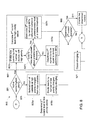
- Fig. 7 , Fig. 8 , and Fig 9 are flow diagrams of example methods 700, 800, and 900 for supplying current to a power storage device, such as power storage device 106, that may be used with charging device 104 (both shown in Fig. 1 ).
- any of methods 700, 800, and 900 are embodied within a plurality of instructions stored within memory device 204, and is at least partially executed by processor 202 (both shown in Fig. 2 ).
- any of methods 700, 800, and 900 may be used with any of methods 400, 500, and 600, or in conjunction with any other method that enables system 300 to function as described herein.
- a first charging device 104 such as for example an active first charging device 302 in possession of a network token 331 determines 510b ( Fig. 5 ) a first priority of the first charging device 302 relative to the remaining charging devices 104 in the network 316.
- the priority of the first charging device 302 may be higher, lower, or the same as any of the remaining charging devices 104 in the network 316.
- the first charging device 302 determines 701a whether the first priority level of the first charging device 302 has the lowest priority level relative to at least a second charging device 304 in the network 316.
- the available current for example, the current distribution limit minus the total current supplied from distribution device 310
- the available current is determined at 705a to be below a predetermined minimum threshold
- the current control device 214 is operated to prevent current flow to the charging device 302. If the available current is determined at 705a to be above the predetermined minimum threshold, then the second or revised amount of current to be at least one of received by the first charging device 302 from the electrical supply 310 or supplied to power storage device 106, is determined at 707.
- the first charging device 302 is not the lowest priority charging device, then at 701b it is determined whether the first charging device 302 is currently the highest priority charging device. If the first charging device 302 is determined 701b to currently have the highest priority level, then at 705c, it is determined whether a maximum charging current level is available (for example, an amount and/or rate of current requested by vehicle controller 110). If it is determined at 705c that the maximum charging current level is not available, then the second or revised amount of current to be at least one of received by the first charging device 302 from the electrical supply 310 or supplied to power storage device 106, is determined at 707.
- a maximum charging current level for example, an amount and/or rate of current requested by vehicle controller 110
- the second or revised amount of current to be at least one of received by the first charging device 302 from the electrical supply 310 or supplied to power storage device 106 is determined at 707.
- the second current level to be one of received or supplied by a first charging device may be determined 707 according to predetermined rules.
- the second current level to be one of received or supplied by a first charging device may be determined iteratively or progressively according to predetermined rules.
- the charging devices 104 may be assigned a priority from selected from a tiered priority system comprising 4 levels, such as priority level 1 (i.e., highest priority) through priority level 4 (i.e., lowest priority). In an embodiment, if it is determined 701a, 701b that first charging device 104 is neither the highest priority (i.e. priority level 1) nor the lowest priority (i.e.
- the second current level may be determined 705b by first determining an incremental or step current level, and subsequently enabling an increase to the second determined current for each charging device 104 at each incremental priority level (e.g., 2, 3) by an amount corresponding to the determined step current.
- each incremental priority level e.g. 2, 3
- the determined step current may be determined by subtracting the minimum available current threshold from the maximum available current and then dividing the difference by a number that is equal to one greater than the number of all the operating chargers 104 in network 316 that are currently neither the highest nor the lowest priority (i.e., in this example, 3). Thereafter, in the event that another charging device 304 is determined 705a, 705b to be neither the highest priority (i.e. priority level 1) nor the lowest priority (i.e. priority level 4), but is determined to be a higher priority level than charging device 306, then the second current level for charging device 304 may be determined by doubling the determined step current.
- network 316 may comprise 4 charging devices 302, 304, 306, and 308, wherein the charging devices have a corresponding determined priority level of one of 1 (highest), 2, 3, and 4 (lowest) respectively. If, for example, in the event the charging parameters for priority level 1 charging device 302 are determined to be as follows: minimum available current is 5 amperes (A), the maximum available current for the network 316 is 75 amperes, the minimum charging current is 5 amperes, and the maximum charging current is about 30 amperes, then charging device 302, as the highest priority device, will determine 705c its second current to be about 30 amperes.
- minimum available current is 5 amperes (A)
- the maximum available current for the network 316 is 75 amperes
- the minimum charging current is 5 amperes
- the maximum charging current is about 30 amperes
- priority level 4 charging device 308 as the lowest priority device will thereafter determine 705a its second current to be about 5 amperes. Thus, in this example, about 40 amperes remain available for the remaining two charging devices 304, 305.
- the spare current capacity for the network 316 may be used to increase the second determined current of a higher priority charging device 104 up to the maximum current for that charging device 104.
- the second determined current for any lower priority chargers 302, 304 may be reduced, for example to the predetermined minimum current.
- the above represent examples only, and thus are not intended to limit in any way the determination of a second amount or rate of current based at least in part on a priority of a charging device.
- the second current level to be one of received or supplied by a first charging device may be determined according to any number of predetermined rules that enable charging system 300 to function as described herein.
- the active charging device 302 determines 707 the second amount of current by negotiating an acceptable current level with the vehicle controller 110 ( Fig. 1 ).
- the second current level may be selected from a range of current levels progressing from a predetermined minimum current level to a predetermined maximum current level.
- the second current level is selected from a range of acceptable current levels progressing from the predetermined minimum current level to the predetermined maximum current level, the range of current levels corresponding to the priority order of the charging devices 104, from the lowest priority charging device 104 to the highest priority charging device 104.
- first charging device 302 enables 711a the second current determined at 705b to flow.
- processor 202 controls or closes current control device 214 to enable that the determined second current is at least one of received by the first charging device 302 from the electrical supply 310 or supplied to power storage device 106.
- first charging device 302 enables at 711b the maximum charging current determined at 705b to flow.
- a first charging device 302 having a priority that is lower than a second charging device 304 will be required to lower its maximum current level before the second charging device 304 may be required to lower its maximum current level.
- the charging devices 104 on network 316 having higher priorities may then be required to adjust their stored charging parameters and to determine a lower second current to be at least one of received by the respective charging device 104 from the electrical supply 310 or supplied to power storage device 106. Accordingly, at least a minimum charging current level at all charging devices 104 on network 316 may be maintained unless the predetermined current threshold of the network 316 would be exceeded. If so, the charging devices 104 having low priority will be required to cease charging respective power storage devices 106 until at least a minimum predetermined current is available.
- a first charging device 104 such as for example an active first charging device 302 in possession of network token 331 determines 510b ( Fig. 5 ) a first priority of the first charging device 302 relative to the remaining charging devices 104 in the network 316.
- the priority of the first charging device 302 may be higher, lower, or the same as any of the remaining charging devices 104 in the network 316.
- the first charging device 302 determines 801 whether the first priority level of the first charging device 302 has the highest priority level relative to at least a second charging device 304 in the network 316.
- an available second amount or rate of current for the low priority charging device 302 is determined. For example, in an embodiment, at 805a, the sum of the currents provided to the high priority chargers in network 316 is subtracted from a predetermined current threshold of network 316 to determine a net maximum current available for any charging devices 104 having a low priority. Thereafter, at 805b the current determined at 805a is divided by the number of charging devices 104 in the network 316 having a low priority and currently charging to determine the second current level to be least one of received by the low priority charging device 302 from the electrical supply 310 or supplied to power storage device 106.
- the predetermined current threshold of the network 316 is divided by the number of charging devices 104 in the network 316 having a high priority and currently charging. Thereafter, at 807b it is determined if the current determined at 807a is greater than a predetermined maximum threshold current, and if so, the second current to be at least one of received by the first charging device 302 from the electrical supply 310 or supplied to power storage device 106 is determined at least in part by reducing 807c the current determined at 807a to a predetermined current level.
- the predetermined maximum threshold current is 30 Amperes
- the current determined at 807a is 40 Amperes
- the second current is determined to be 30 Amperes, or less.
- the second current is determined to be at least one of received by the first charging device 302 from the electrical supply 310 or supplied to power storage device 106 is determined to be equal to the current determined at 807a.
- the second current to be at least one of received by the first charging device 302 from the electrical supply 310 or supplied to power storage device 106 is determined at 807, it is then determined at 809 if the determined second current is available.
- the current control device 214 is operated to prevent current flow to the charging device 302 and charging ceases. Conversely, if at 809 it is determined that the determined second current is available and the available current is above a predetermined minimum threshold, then at 811 the current control device 214 is operated to enable current flow to the charging device 302.
- the current control device 214 may be operated to enable the available current to the charging device 302.
- a first charging device 302 having a priority that is higher than a priority of a second charging device 304 in the network 316 will be able to one of receive or provide a desired maximum current level, while a second charging device 304 may be required to determine a lower second current to be at least one of received by the charging device 104 from the electrical supply 310 or supplied to power storage device 106.
- the second current level determined by the charging device 304 having a lower priority may be incrementally reduced until a predetermined minimum current threshold is met.
- one or more high priority charging devices 104 in the network 316 may be enabled to one of receive or provide a desired maximum current level. Accordingly, any remaining charging devices 104 on the network 316 having a low priority determine their respective second current level based at least in part on the maximum current levels of the one or more high priority charging devices 104. In yet another embodiment, based at least in part on the predetermined current threshold of the network 316, charging devices 104 on the network 316 having a low priority may be required to one of receive or provide a second current level at a predetermined minimum current level.
- additional vehicles 102 may not be authorized to receive current at a high priority level, but may be authorized to receive charging current at a low priority level.
- a first charging device 104 such as for example an active first charging device 302 in possession of a network token 331 determines 510b ( Fig. 5 ) a first priority the first charging device 302 relative to the remaining charging devices 104 in the network 316.
- the priority of the first charging device 302 may be higher, lower, or the same as any of the remaining charging devices 104 in the network 316.
- the first charging device 302 determines 901 whether the first priority level of the first charging device 302 has the lowest priority level relative to at least a second charging device 304 in the network 316.
- the first charging device 302 is not the highest priority device in the network 316, that is, is currently a low priority charging device, then at 905 an available second amount or rate of current for the low priority charging device 104 is determined. For example, in an embodiment, at 905a, the sum of the currents provided to the high priority chargers in network 316 is determined, and at 905b, the sum determined at 905a is subtracted from the predetermined current threshold of network 316 to determine a maximum current available for any charging devices 104 having a low priority. Thereafter, at 905c the current determined at 905b is divided by the number of charging devices 104 in the network 316 having a low priority and currently charging. Thereafter, at 908 it is determined whether the current determined at 905c is above a predetermined minimum threshold.
- first charging device 302 determines whether the current determined at 907 is currently available.
- the current control device 214 is operated to prevent current flow to the charging device 302 and charging ceases. In an embodiment, if at 909 it is determined that the second current determined at 907 is not available, it is thereafter determined at 910 if the available current is above a predetermined minimum current. In the event that the available current is determined 910 to be above a predetermined minimum, then then at 911 the current control device 214 may be operated to enable the available current to the charging device 302.
- first charging device 302 enables the second current determined or 907 to flow.
- processor 202 controls or closes current control device 214 to enable that the determined second current is at least one of received by the first charging device 302 from the electrical supply 310 or supplied to power storage device 106.
- first charging device 302 enables at 911 the second current level determined 905c to flow.
- each charging device 104 within network 316 determines an amount of current to draw from the distribution device 310 based at least in part on a determined priority of at least one of the charging devices 104. Through the determination of the second amount of current, an embodiment substantially controls the amount of current that is at least one of received by the first charging device 302 from the electrical supply 310 or supplied to power storage device 106 by each charging device 104, while preventing an overload on the electrical supply 310. As such, the current distribution limit of electrical distribution device 310 is not exceeded.
- Example embodiments of a system, a charging device, and a method of supplying current to a power storage device are described above in detail.
- the system, charging device, and method are not limited to the specific embodiments described herein, but rather, components of the system and/or charging device and/or steps of the method may be utilized independently and separately from other components and/or steps described herein.
- the charging device may also be used in combination with other power systems and methods, and is not limited to practice with only the electric vehicle as described herein. Rather, the example embodiment can be implemented and utilized in connection with many other power system applications.
Landscapes
- Engineering & Computer Science (AREA)
- Power Engineering (AREA)
- Transportation (AREA)
- Mechanical Engineering (AREA)
- Manufacturing & Machinery (AREA)
- Chemical & Material Sciences (AREA)
- Chemical Kinetics & Catalysis (AREA)
- Electrochemistry (AREA)
- General Chemical & Material Sciences (AREA)
- Life Sciences & Earth Sciences (AREA)
- Sustainable Development (AREA)
- Sustainable Energy (AREA)
- Charge And Discharge Circuits For Batteries Or The Like (AREA)
- Electric Propulsion And Braking For Vehicles (AREA)
- Secondary Cells (AREA)
Abstract
Description
- The present application relates generally to charging devices and, more particularly, to a system, a charging device, and a method of supplying current to a power storage device.
- As electric vehicles and/or hybrid electric vehicles have gained popularity, an associated need to manage delivery of electrical energy to such vehicles has increased. In addition, a need to provide safe and efficient charging devices or stations has been created by the increased use of such vehicles.
- At least some known charging stations include a power cable or other conductor that may be removably coupled to the electric vehicle. The charging stations receive electricity from an electric utility distribution network or another electricity source, and deliver electricity to the electric vehicle through the power cable.
- In at least some electric utility distribution networks, a plurality of charging devices receive electricity from a common electrical distribution component, such as a transformer. However, if each charging device operates concurrently to supply charging current to an electric vehicle, the current supplied to the electrical distribution component may exceed a rated current limit of the component. In such situations, the electrical distribution component may be damaged and/or a circuit breaker or another protection device may activate to disable power to all charging devices coupled to the electrical distribution component.
- At least some known electric vehicle (EV) charging stations or other electric vehicle supply equipment (EVSE) employ a dedicated master control to manage current draw from a group of EVSEs that are connected to the same electrical supply such as a utility distribution network, and are protected by the same overcurrent protection such as main breaker.
- Such a conventional master controller or device is typically employed to monitor and control the maximum amount of current an EV charger or EVSE can provide to a vehicle based on the electrical supply the EVSE is connected to.
- When some conventional electric utility distribution networks are connected to a plurality of EVSE chargers, particularly when those EVSE chargers are functioning to provide charging currents at or near their maximum ratings, the networks are not able to support all the chargers. For example, if the group of EVSE chargers exceeds the a predetermined current limit for the distribution network, circuit protection devices in the network may trip or open to shut off current flow to the EVSE chargers resulting in no vehicles being charged.
- Additionally there is a need for conventional EVSE charging networks to selectively draw current from the distribution network, or provide charging current to a storage device based at least in part on a relative priority that is assigned to an EVSE charger or user.
- Embodiments include systems, devices, and methods for use in supplying current to a plurality of power storage devices without need of a dedicated master device.
- In one aspect, a system for use in supplying current from an electrical supply to a plurality of power storage devices is disclosed. The system includes a first charging device configured to receive current from the electrical supply, and configured to supply current to a first power storage device of the plurality of power storage devices. The first charging device includes a current control device coupled to said first charging device, configured to selectively enable a current to be at least one of received from the electrical supply or supplied to the first power storage device, and at least one second charging device coupled to the first charging device to form a network, the second charging device configured to receive current from the electrical supply, and configured to supply current to a second power storage device of the plurality of power storage devices. The first charging device includes a first processor programmed to determine a first charging parameter and a first priority associated with the first charging device, and a second charging parameter and a second priority associated with the second charging device. The first processor is further configured to determine a second amount of current to be at least one of received from the electrical supply or supplied to the first power storage device, based at least in part on the determined first and the second charging parameters and the first and second priority, and to enable the determined second amount of current to be at least one of received by said first charging device or supplied to the first power storage device.
- In another aspect, a charging device for charging a power storage device is disclosed. The charging device includes a current control device configured to selectively enable a current to be at least one of received from the electrical supply or supplied to the power storage device, and a network interface configured to couple to at least one second charging device to form a network. The charging device also includes a processor coupled to the current control device. The processor is programmed to determine a first charging parameter and a first priority associated with the first charging device, and to determine a second charging parameter and a second priority associated with the second charging device. The processor is further programmed to determine a second amount of current to be at least one of received from the electrical supply or supplied to the first power storage device, based at least in part on the determined first and said second charging parameters and the first and second priority, and to enable the determined second amount of current to be at least one of received by said first charging device or supplied to the power storage device.
- In yet another aspect, a method of supplying current to a power storage device is disclosed. The method includes configuring at least a first charging device and a second charging device within a network, wherein the first charging device includes a current control device configured to selectively enable a current to be at least one of received from the electrical supply or supplied to the power storage device. The method also includes determining whether said first charging device possesses a network token, and if so, determining a first charging parameter and a first priority associated with the first charging device, and determining a second charging parameter and a second priority associated with the second charging device. The method further includes determining a second amount of current to be at least one of received from the electrical supply or supplied to the first power storage device, based at least in part on the determined first and said second charging parameters and said first and second priority, and enabling the determined second amount of current to be at least one of received by the first charging device or supplied to the first power storage device.
- Reference is now made briefly to the accompanying drawings, in which:
-
Fig. 1 is a block diagram of an example system for charging an electric vehicle. -
Fig. 2 is a block diagram of an example charging device that may be used with the system shown inFig. 1 ; -
Fig. 3 is a block diagram of an example charging system for charging a plurality of electric vehicles that may be used with the system shown inFig. 1 ; -
Fig. 4 is a flow diagram of an example method of supplying current to a power storage device that may be used with the charging device shown inFig. 2 ; -
Fig. 5 is a flow diagram of an example method of supplying current to a power storage device that may be used with the charging device shown inFig. 2 ; -
Fig. 6 is a flow diagram of an example method of supplying current to a power storage device that may be used with the charging device shown inFig. 2 . -
Fig. 7 is a flow diagram of an example method of supplying current to a power storage device that may be used with the charging device shown inFig. 2 . -
Fig. 8 is a flow diagram of an example method of supplying current to a power storage device that may be used with the charging device shown inFig. 2 ; and -
Fig. 9 is a flow diagram of an example method of supplying current to a power storage device that may be used with the charging device shown inFig. 2 . - In some embodiments, the term "electric vehicle" refers generally to a vehicle that includes one or more electric motors. Energy used to power the motors may come from various sources, such as, but not limited to, an on-board rechargeable battery and/or an on-board fuel cell. In one embodiment, the electric vehicle is a hybrid electric vehicle, which captures and stores energy generated, for example, by braking. A hybrid electric vehicle uses energy stored in an electrical source, such as a battery, to continue operating when idling to conserve fuel. Some hybrid electric vehicles are capable of recharging the battery by plugging into a power receptacle, such as a power outlet. Accordingly, the term "electric vehicle" as used herein may refer to a hybrid electric vehicle or any other vehicle to which electrical energy may be delivered, for example, via the power grid.
-
Fig. 1 illustrates anexample system 100 for use in charging, or providing electricity to anelectric vehicle 102. In an example embodiment,system 100 includes acharging device 104 coupled toelectric vehicle 102. In an embodiment,electric vehicle 102 includes at least onepower storage device 106, such as a battery and/or any other storage device, coupled to amotor 108. In an example embodiment,electric vehicle 102 also includes avehicle controller 110 coupled topower storage device 106. - In an example embodiment,
charging device 104 is removably coupled topower storage device 106 and tovehicle controller 110 by at least onepower conduit 112. Alternatively,charging device 104 may be coupled topower storage device 106 and/orvehicle controller 110 by any other conduit or conduits, and/orcharging device 104 may be coupled tovehicle controller 110 by a wireless data link (not shown). In an example embodiment,power conduit 112 includes at least one conductor (not shown) for supplying electricity topower storage device 106 and/or to any other component withinelectric vehicle 102, and at least one conductor (not shown) for transmitting data to, and receiving data from,vehicle controller 110 and/or any other component withinelectric vehicle 102. Alternatively,power conduit 112 may include a single conductor that transmits and/or receives power and/or data, or any other number of conductors that enablessystem 100 to function as described herein. In an example embodiment,charging device 104 is coupled to anelectric power source 114, such as a power grid of an electric utility company, a generator, a battery, and/or any other device or system that provides electricity to chargingdevice 104. - In an example embodiment,
charging device 104 is coupled to at least oneserver 116 through a network, such as the Internet, a local area network (LAN), a wide area network (WAN), and/or any other network or data connection that enablescharging device 104 to function as described herein. -
Server 116, in an example embodiment, communicates withcharging device 104, for example, by transmitting a signal to chargingdevice 104, for example to authorize payment and/or delivery of electricity topower storage device 106, to access customer information, and/or to perform any other function that enablessystem 100 to function as described herein. - In an example embodiment,
server 116 andvehicle controller 110 may each include at least one processor and at least one memory device. The processors each include any suitable programmable circuit which may include one or more systems and microcontrollers, microprocessors, reduced instruction set circuits (RISC), application specific integrated circuits (ASIC), programmable logic circuits (PLC), field programmable gate arrays (FPGA), and any other circuit capable of executing the functions described herein. The above represent examples only, and thus are not intended to limit in any way the definition and/or meaning of the term "processor." The memory devices each include a computer readable medium, such as, without limitation, random access memory (RAM), flash memory, a hard disk drive, a solid state drive, a diskette, a flash drive, a compact disc, a digital video disc, and/or any suitable memory device that enables the processors to store, retrieve, and/or execute instructions and/or data. - During operation, in an example embodiment, a user couples the
power storage device 106 of the vehicle to thecharging device 104 using thepower conduit 112. In one embodiment, thepower conduit 112 is a cable having a connector at one end that removably and electrically couples with a corresponding connector of thecharging device 104. - The user may access a user interface device (not shown in
Fig. 1 ) of chargingdevice 104 to enter information, such as payment information, and/or to initiate power delivery topower storage device 106. The chargingdevice 104 is configured to communicate withserver 116, for example, to authenticate the user, to process the payment information, and/or to approve or authorize the power delivery. If thecharging device 104 receives a signal fromserver 116 that indicates approval or authorization to deliver power to thepower storage device 106, the chargingdevice 104 receives power fromelectric power source 114 and provides the power topower storage device 106 throughpower conduit 112. The chargingdevice 104 communicates with thevehicle controller 110 wirelessly, through thepower conduit 112, and/or through any other conduit, to control and/or to monitor the delivery of power to thepower storage device 106. For example, thevehicle controller 110 transmits signals to thecharging device 104 indicating a charge level of thepower storage device 106 and/or a desired amount and/or rate of electricity, such as a maximum current level to be provided by the chargingdevice 104. In addition, the chargingdevice 104 transmits signals to thevehicle controller 110 indicating an amount and/or rate of electricity being delivered to thepower storage device 106. Additionally or alternatively, the chargingdevice 104 and/or thevehicle controller 110 may transmit and/or receive any other signals or messages that enable thesystem 100 to function as described herein. When thepower storage device 106 has been charged to a desired level, the chargingdevice 104 ceases delivering power to thepower storage device 106 and the user may disengage thepower conduit 112 from thepower storage device 106. -
Fig. 2 is a block diagram of anexample charging device 104 that may be used with system 100 (shown inFig. 1 ). In an example embodiment, chargingdevice 104 includes acontroller 200 that comprises aprocessor 202 and amemory device 204. As described more fully herein,controller 200 is coupled to anetwork interface 206, to adisplay 208, to auser interface device 210, to ameter 212, and to acurrent control device 214. -
Processor 202 includes any suitable programmable circuit which may include one or more systems and microcontrollers, microprocessors, reduced instruction set circuits (RISC), application specific integrated circuits (ASIC), programmable logic circuits (PLC), field programmable gate arrays (FPGA), and any other circuit capable of executing the functions described herein. The above represent examples only, and thus are not intended to limit in any way the definition and/or meaning of the term "processor."Memory device 204 includes a non-transitory computer readable medium, such as, without limitation, random access memory (RAM), flash memory, a hard disk drive, a solid state drive, a diskette, a flash drive, a compact disc, a digital video disc, and/or any suitable device that enablesprocessor 202 to store, retrieve, and/or execute instructions and/or data. -
Network interface 206, in an example embodiment, transmits and receives data betweencontroller 200 and a remote device or system. In an example embodiment,network interface 206 is communicatively coupled to at least oneother charging device 104 such that chargingdevices 104 transmit and receive data to and from each other. In an example embodiment,network interface 206 is coupled to anetwork interface 206 of at least oneother charging device 104 using any suitable data conduit, such as an Ethernet cable, a Recommended Standard (RS) 485 compliant cable, and/or any other data conduit that enables chargingdevice 104 to function as described herein. Alternatively,network interface 206 communicates wirelessly with anetwork interface 206 of at least oneother charging device 104 using any suitable wireless protocol. - In an example embodiment,
display 208 includes a vacuum fluorescent display (VFD) and/or one or more light-emitting diodes (LED). Additionally or alternatively,display 208 may include, without limitation, a liquid crystal display (LCD), a cathode ray tube (CRT), a plasma display, and/or any suitable visual output device capable of displaying graphical data and/or text to a user. In an example embodiment, a charging status of power storage device 106 (shown inFig. 1 ), payment information, user authentication information, and/or any other information may be displayed to a user ondisplay 208. -
User interface device 210 includes, without limitation, a keyboard, a keypad, a touch-sensitive screen, a scroll wheel, a pointing device, a barcode reader, a magnetic card reader, a radio frequency identification (RFID) card reader, an audio input device employing speech-recognition software, and/or any suitable device that enables a user to input data into chargingdevice 104 and/or to retrieve data from chargingdevice 104. In an example embodiment, the user may operateuser interface device 210 to initiate and/or terminate the delivery of power topower storage device 106. In one embodiment, the user may input user authentication information and/or payment information usinguser interface device 210. - In an example embodiment,
current control device 214 is coupled topower conduit 112 and tometer 212. In an example embodiment,current control device 214 is a contactor 214 coupled to, and controlled by,controller 200. In an example embodiment,controller 200 operates, or openscontactor 214 to interrupt the current flowing throughpower conduit 112 such thatpower storage device 106 is electrically disconnected from electric power source 114 (shown inFig. 1 ).Controller 200 also closescontactor 214 to enable current to flow throughpower conduit 112 such thatpower storage device 106 is electrically connected toelectric power source 114. -
Meter 212 is coupled topower conduit 112 and tocontroller 200 for use in measuring and/or calculating the current, voltage, and/or power provided fromelectric power source 114 topower storage device 106.Meter 212 transmits data representative of the measured current, voltage, and/or power tocontroller 200. - In an example embodiment, a
current protection device 216 is coupled tometer 212 and toelectric power source 114. Thecurrent protection device 216 electrically isolates ordisconnects charging device 104 from the electric power source 114 (Fig. 1 ) if the current received from theelectric power source 114 exceeds a predetermined threshold or current limit. In an example embodiment,current protection device 216 is a circuit breaker. Alternatively,current protection device 216 may be a fuse, a relay, and/or any other device that enablescurrent protection device 216 to function as described herein. - In an example embodiment,
memory device 204 may be configured to store an identification number (ID) of thecorresponding charging device 104. For example, the ID may be a Media Access Control (MAC) address, Internet Protocol (IP) address, a user-assigned unique identifier, or any other convenient ID). - In an example embodiment,
memory device 204 is additionally configured to store data indicative of any number of charging parameters. The charging parameters may include any desired parameters. Examples of charging parameters may include, without limitation, a maximum desired current level (for example, an amount and/or rate of current requested by a vehicle controller 110); a maximum current setting (for example, a maximum current the chargingdevice 104 may provide to power storage device 106); a supply current (for example, an amount and/or rate of current supplied by chargingdevice 104 to power storage device 106); a current usage, (for example, the present current level or rate drawn by the chargingdevice 104 from electrical distribution device 310); a charging duration (for example, aduration charging device 104 has been charging power storage device 106); and a charging status (for example, whether chargingdevice 104 is presently charging power storage device 106). In an embodiment, the stored charging parameters inmemory device 204 also includes charging parameter data related to or received from other chargingdevices 104 in a network 316 (FIG 3 ). In another example embodiment, the stored charging parameters inmemory device 204 also include a current threshold for the network 316 (for example, a predetermined threshold or current distribution limit of theelectric power source 114. - In an example embodiment,
memory device 204 is additionally configured to store charging parameter data to be used to determine a priority such as a conditional priority or priority level assigned to thecharging device 104. The charging parameter data used to determine the conditional priority level data may include, without limitation, one or more of the charging parameters of thecharging device 104, and/or a location of thecharging device 104, and/or an identity of a user. In an embodiment, the priority level of acharging device 104 is determined based on predetermined conditions or rules. It is contemplated that the determined priority or priority level of a charging device may be characterized as a simple High or Low priority, or as a tiered priority, such as one of High, Medium, or Low, or any other priority level designation that enables chargingsystem 300 to function as described herein. It is further contemplated that one ormore charging devices 104 may have an identical priority level at the same time. - In one embodiment, the priority level of a
charging device 104 orvehicle 102 is determined based at least in part on the charge duration and status of therespective charging device 104. If acharging device 104 in the network 316 (Fig. 3 ) is currently determined to be charging a firstpower storage device 106, and thecharging device 104 is further determined to currently have a charge duration that is longer than one or more of theother charging devices 104 in the network, it may be assigned a lower priority level than asecond charging device 104 innetwork 316 having a shorter charge duration. Conversely, acharging device 104 in thenetwork 316 that is determined to currently have a charge duration that is shorter than one or more of theother charging devices 104 in the network, may be assigned a higher priority than asecond charging device 104 innetwork 316 having a longer charge duration. - In another embodiment, the priority of a
charging device 104 is determined based at least in part on a determined charge level of apower storage device 106. For example, for afirst charging device 104 in thenetwork 316 that is charging apower storage device 106 having a charge level that is presently higher than the charge level of one or morepower storage devices 106 being charged by other chargingdevices 104 onnetwork 316, may be assigned lower priority than asecond charging device 104 innetwork 316 that is charging a secondpower storage device 106 having a lower charge level. In other words, for this example embodiment, the higher thepower storage device 106 charge level, the lower the priority that may be assigned to thecorresponding charging device 104. - In another embodiment, the priority of a
charging device 104 is determined based at least in part on the physical location of thecharging device 104. - In another embodiment, the priority of a
charging device 104 is determined based at least in part on the time of day, or any other time-dependent attribute, such as day, week, month, or year that enables chargingsystem 300 to function as described herein. - In yet another embodiment, the priority of a
charging device 104 is determined based at least in part upon a determined identity of a user and/or a determined identity of avehicle 102. It is contemplated that the determined identity of the user may be based on an individual user and/or a group of users, such as for example employees of a predetermined company, emergency personnel, or any other user designation that enables chargingsystem 300 to function as described herein. For example, afirst charging device 104 operated by a first predetermined user may be assigned a higher priority than asecond charging device 104 in the network 316 (Fig. 3 ) operated by a second user, based on predetermined priority rules for thenetwork 316. Similarly, it is also contemplated that the determined identity of avehicle 102 may be based on and individual vehicle and/or a group of vehicles, such as for example vehicles operated by a predetermined company, or any other user designation that enables chargingsystem 300 to function as described herein. - During operation,
power storage device 106 ofelectric vehicle 102 is coupled to chargingdevice 104 usingpower conduit 112. In one embodiment, a user obtains authorization fromserver 116 and/or another system or device to enable chargingdevice 104 to charge (i.e., to provide electrical current to)power storage device 106. As described more fully herein, chargingdevice 104 determines an amount or rate of current to provide topower storage device 106 based on predetermined parameters. For example, in various embodiments, the predetermined parameters may comprise the stored charging parameters inmemory 204 such as, for example without limitation, the number of chargingdevices 104 within the network, the total current usage of the chargingdevices 104 innetwork 316, the supply current and/or the current usage of one ormore charging devices 104 on thenetwork 316, the desired maximum current level of one or morepower storage devices 106 coupled to thenetwork 316, the current distribution limit of theelectrical distribution device 114 that chargingdevices 104 are coupled to, or a conditional priority of one ormore charging devices 104 on thenetwork 316. -
Fig. 3 is a block diagram of anexample charging system 300 that may be used to charge a plurality ofelectric vehicles 102, such as by charging a power storage device 106 (both shown inFig. 2 ) of eachelectric vehicle 102. In an example embodiment, chargingsystem 300 includes a plurality of chargingdevices 104, such as afirst charging device 302, asecond charging device 304, athird charging device 306, and afourth charging device 308. WhileFig. 3 illustrates fourcharging devices 104, chargingsystem 300 may include any number of chargingdevices 104 as desired. - In an example embodiment, charging
devices 104 are coupled to a commonelectrical distribution device 310 throughrespective power conduits 312. In an example embodiment,electrical distribution device 310 is atransformer 310 that adjusts a distribution voltage received fromelectric power source 114 to a voltage suitable for use with chargingdevices 104. Alternatively,electrical distribution device 310 may be any other device that enables chargingsystem 300 to function as described herein. In an example embodiment,electrical distribution device 310 distributes current to each chargingdevice 104 until the distributed current reaches a current distribution limit ofelectrical distribution device 310. For example,electrical distribution device 310 may be designed or "rated" to distribute a predefined amount of current. Accordingly, the current distribution limit may be set to the predefined amount of current or a current level below the predefined amount. As described more fully herein, in an embodiment, each chargingdevice 104 determines an amount or rate of current to draw fromelectrical distribution device 310 based on predetermined parameters. For example, the amount or rate of current for chargingdevice 104 to draw fromelectrical distribution device 310 may be determined in various embodiments as a function of the current distribution limit, the amount of current being drawn from other chargingdevices 104, and/or the number of chargingdevices 104 within a network. Alternatively, chargingdevices 104 are coupled to a plurality ofelectrical distribution devices 310 and each chargingdevice 104 determines the amount of current to supply topower storage device 106 based on predetermined parameters, for example, as a function of the current distribution limits ofelectrical distribution devices 310, the amount of current drawn from other chargingdevices 104, and/or the number of chargingdevices 104 within one or more networks. Chargingdevices 104, in an example embodiment, are coupled together in data communication by adata bus 314. More specifically, chargingdevices 104 are coupled todata bus 314 by respective network interfaces 206 (Fig. 2 ). In an example embodiment,data bus 314 includes at least one data conduit (not shown), such as an Ethernet cable, a Recommended Standard (RS) 485 compliant cable, and/or any other data conduit that enablesdata bus 314 to function as described herein. Alternatively, chargingdevices 104 are coupled together in data communication by a wireless network. In an example embodiment, chargingdevices 104 and/ordata bus 314 form a peer-to-peer type network 316 that enables each chargingdevice 104 to exchange data with other chargingdevices 104 coupled tonetwork 316 without requiring a master controller. Alternatively, chargingdevices 104 and/ordata bus 314 may form any other network that enables chargingsystem 300 to function as described herein. WhileFig. 3 depicts a token-ringtype communication network 316 having a ring topology, it is contemplated that any desired network topology may be employed, such as ring with a hub, star, mesh, tree, or any other topology capable of executing the functions described herein. - With reference to
Figures 2 and3 , in an example embodiment, thememory device 204 of each chargingdevice 104 in thenetwork 316 is also configured to receive and store an identification number (ID) of the remainingcharging devices 104 in thenetwork 316. In an example embodiment, each chargingdevice 104 transmits at least one request to eachother charging device 104 to receive data regarding the identification number (ID) of eachother charging device 104. During operation, each chargingdevice 104 in thenetwork 316 may communicate the ID stored in itsrespective memory device 204 to each of the remainingcharging devices 104 in thenetwork 316. - Alternatively, each charging device may receive data regarding the identification number (ID) from another source, such as from a remote computer (not shown), from a subset of charging
devices 104 coupled tonetwork 316, and/or from any other source that enables chargingsystem 300 to function as described herein. - In an embodiment, during operation, control of a
network token 331 is determined. In an embodiment, a contention procedure is initiated wherein afirst charging device 302 negotiates with asecond charging device 304 and anyother charging devices network 316 for the control of thenetwork 316. For example, the chargingdevice 104 with the highest ID is designated as the present active device, while the remaining charging devices are designated as standby devices. In an example embodiment, the chargingdevice 104 designated as the present active device generates thenetwork token 331. In another embodiment, the token 331 is generated and provided to thecharging device 104 currently which is then designated as the active device. In an embodiment, the chargingdevice 104 currently in possession of thenetwork token 331 is designated as the present active device, while the remainingcharging devices 104 are designated as present standby devices. - After a predetermined period, the
network token 331 is then passed from the chargingdevice 104 designated as the present active device to anext charging device 104 in thenetwork 316 based on predetermined parameters. In an example embodiment, thenext charging device 104 is the charging device having a next lowest ID from the present active device. Upon receipt of the token 331, thenext charging device 104 receiving the token 331 is then in turn designated as the present active device, and the remainingcharging devices 104 are designated as present standby devices. The token 331 likewise continues to be passed in turn to each of the chargingdevices 104 in thenetwork 316. It will be understood that whileFig. 3 depicts chargingdevice 302 as possessing thenetwork token 331, in operation and as described herein, the network token may be possessed by any one of the chargingdevices 104, and by only onecharging device 104 at any one time. - In an embodiment, each charging
device 104 is configured to transmit a charging parameter data request to the remainingcharging devices 104 on thenetwork 316, only when thecharging device 104 is in possession of thenetwork token 331. In this way, data collisions onnetwork 316 can be avoided. In an embodiment, possession of thenetwork token 331 allows the charging device designated as the presentactive device 104 to request charging parameter data from the remainingcharging devices 104 on thenetwork 316. Possession of thenetwork token 331 also allows thecharging device 104 to change any predetermined parameters, such as the maximum current setting (for example, a maximum current the chargingdevice 104 may provide to power storage device 106) or the present current usage of charging device 104 (for example, the present current level or rate drawn by the chargingdevice 104 from electrical distribution device 310). - As described more fully herein, in an example embodiment,
controller 200 offirst charging device 302 is configured to determine whether thedevice 302 is in possession of thenetwork token 331. When possession of thenetwork token 331 is determined, thecontroller 200 offirst charging device 302 transmits at least one request to at least asecond charging device 304 to receive at least a first charging parameter, such as for example without limitation, data regarding the supply current, expected supply current, current usage, expected current usage, and priority level of at least thesecond charging device 302. As used herein, the term "supply current" refers generally to an amount or rate of current supplied or expected to be supplied by acharging device 104. As used herein, the term "current usage" refers generally to an amount or rate of current drawn or expected to be drawn by at least onecharging device 104 fromelectrical distribution device 310. - In an embodiment,
Controller 200 of each chargingdevice 104 is configured to allow the transmission of a request for charging parameters of anothercharging device 104 only when thecharging device 104 making the request for charging parameters possesses thenetwork token 331. Each chargingdevice 104 that receives the request for charging parameters fromfirst charging device 302 responds by transmitting charging parameter data tofirst charging device 302. In one embodiment, only chargingdevices 104 that are supplying current or that are expecting to supply current respond to the charging parameter data request. In another embodiment, only chargingdevices 104 that are receiving or are expecting to receive current fromelectrical distribution device 310 respond to the charging parameter data request. First chargingdevice 302 receives 511b charging parameter data from eachother charging device 104 withinnetwork 316 and stores the data inmemory 204. Alternatively, each chargingdevice 104 may receive charging parameter data (such as supply current or current usage), from another source, such as from a remote computer (not shown), from a subset of chargingdevices 104 coupled tonetwork 316, and/or from any other source that enables chargingsystem 300 to function as described herein. - In operation, the
controller 200 of each chargingdevice 104 on thenetwork 316 determines its present charging parameters, such as for example, current usage, supply current, maximum current level, maximum current setting, and priority level. Theactive charging device 104 also determines charging parameters, such as for example the current usage, supply current, maximum current level, maximum current setting, and priority level of the remainingcharging devices 104. Theactive charging device 104 transmits a request for the charging parameter data of the remainingcharging devices 104 on thenetwork 316. Theactive charging device 104 subsequently receives the charging parameter and priority data of the remainingcharging devices 104 on thenetwork 316, and may store the received charging parameter and priority data inmemory 204. - The
active charging device 302 also determines network charging parameter data such as without limitation, a current threshold of the network, number of charging devices connected to network 316, or any other desired parameter. For example, in an embodiment,active charging device 302 determines the current threshold of thenetwork 316, and thereafter determines whether the current threshold for the network is exceeded. In an embodiment, network charging parameter data may be stored inmemory 204. - In an embodiment, the presently designated
active charging device 104, determines if it should change any of its charging parameters based at least in part on the determined charging parameters and priority levels of the remainingcharging devices 104 stored inmemory 204. - In an embodiment, a
first charging device 302 presently designated active charging device, determines if it should change any of its charging parameters, such as maximum current setting, based on a determined or assigned priority. For example, afirst charging device 302 may be assigned a lower priority and thereby configured to decrease its maximum current level before asecond charging device 304 being assigned a higher priority. Only after thefirst charging device 302 with a lower assigned priority has lowered its maximum current level to a predetermined minimum threshold, will thesecond charging device 304 with a higher assigned priority be required to lower its maximum current level. Alternatively, any other predetermined conditional priority rules may be used for thenetwork 316 that enablessystem 300 to function as described herein. - Accordingly, in an example embodiment of
system 100 for supplying current from at least oneelectrical supply 310 to at least onepower storage device 106,first charging device 302 is configured to receive current from the electrical supply, and configured to supply current to firstpower storage device 106 of the plurality of power storage devices. At least onesecond charging device 304 is coupled to saidfirst charging device 302 to form anetwork 316. Thesecond charging device 304 is configured to receive current from theelectrical supply 310, and configured to supply current to a secondpower storage device 106 of the plurality of power storage devices. Thefirst charging device 302 comprises afirst processor 204 programmed to determine a first charging parameter associated with said first charging device, determine whether thefirst charging device 302 possesses anetwork token 331, and if so, determine a second charging parameter associated with thesecond charging device 304, determine a second amount of current to be at least one of received from the electrical supply or supplied to the firstpower storage device 302, based at least in part on said determined first and said second charging parameters, and enable the determined second amount of current to be at least one of received by saidfirst charging device 302 or supplied to the firstpower storage device 106. -
Fig. 4 is a flow diagram of anexample method 400 for supplying current to a power storage device, such aspower storage device 106, that may be used with charging device 104 (both shown inFig. 1 ). In an example embodiment,method 400 is embodied within a plurality of instructions stored withinmemory device 204, and is at least partially executed by processor 202 (both shown inFig. 2 ). - In an example embodiment, a
charging device 104, such as first charging device 302 (shown inFig. 3 ), that is requested (e.g., by vehicle controller 110) to supply current to apower storage device 106 coupled thereto initializes 440memory device 204. - At 442, a request for an ID (hereinafter referred to as an "ID request") is transmitted by
first charging device 302 to at least oneother charging device 104 within a network, such as network 316 (shown inFig. 3 ). In an embodiment,first charging device 302 transmits 442 an ID request to eachother charging device 104 within network 316 (such assecond charging device 304,third charging device 306, and/or fourth charging device 308). - Thereafter,
first charging device 302 receives 444 andstores 446 in itsmemory 204 the identification number (ID) data of the remainingcharging devices 104 in thenetwork 316. For example, in an embodiment, each chargingdevice 104 receiving the ID request fromfirst charging device 302 responds by transmitting ID data tofirst charging device 302. First chargingdevice 302 receives 444 the ID data from eachother charging device 104 withinnetwork 316 andstores 446 the received ID data. - In an embodiment, charging
device 104 also transmits 447 its ID data to each of the remainingcharging devices 104 in thenetwork 316. For example,first charging device 302 transmits 447 its ID data to eachother charging device 104 within network 316 (such assecond charging device 304,third charging device 306, and/or fourth charging device 308). - Thereafter, in an embodiment,
first charging device 302 innetwork 316 determines 448 if it should generate thenetwork token 331. For example in an embodiment,first charging device 302 determines if its stored ID is greater than the stored ID of each of the remainingcharging devices 104 in thenetwork 316. Iffirst charging device 302 determines 448 that its ID is greater than the stored ID of each of the remainingcharging devices 104 in thenetwork 316, then thecharging device 302 generates 450 anetwork token 331. - If at 448 it is determined that the ID of
first charging device 302 is not greater than the stored ID of any of the remainingcharging devices 104 in thenetwork 316, then chargingdevice 302 determines 452 if it currently possesses thenetwork token 331. If at 452 it is determined thatfirst charging device 302 does not possess thenetwork token 331, then it is designated 453 to be a present standby device. - If at 450 a
network token 331 is generated by thefirst charging device 302, or if at 452 it is determined that thefirst charging device 302 is in possession of thenetwork token 331, then at 463 thefirst charging device 302 is designated to be the present active device. In an embodiment, if acharging device 104 is designated to be the present active device, that is, in possession of thenetwork token 331, then thecharging device 104 is permitted to change any predetermined parameters, such as for example, a maximum current setting, a supply current, or a current usage. -
Fig. 5 andFig 6 are flow diagrams ofexample methods power storage device 106, that may be used with charging device 104 (both shown inFig. 1 ). In example embodiments, any ofmethods memory device 204, and is at least partially executed by processor 202 (both shown inFig. 2 ). - Referring to
Fig. 5 , in an embodiment, when acharging device 104 possesses thenetwork token 331, theactive charging device 104 determines 510 at least a first charging parameter of the active charging device. For example, at 510a (Fig 6 ), the determined charging parameters preferably include data indicative of a first amount or rate of current being at least one of received or supplied by theactive charging device 104. In an embodiment, at 510b (Fig 6 ) the determined first charging parameter may also comprise any other desired parameter, such as for example maximum current setting, charge duration, charging status, minimum current charging level, and priority level. - Thereafter, the
active charging device 104 determines 511 at least a second charging parameter, such as for example the maximum current setting, current usage, supply current, charge duration, charging status, priority level, or any other desired charging parameter of the remainingcharging devices 104. In an embodiment, theactive charging device 104 determines 511 the charging parameters of the remainingcharging devices 104 stored inmemory 204. - In another embodiment, when a
charging device 302 possesses thenetwork token 331, it determines 511 the charging parameters of the remainingcharging devices 104 by transmitting 511a (Fig. 6 ) a charging parameter data request to the remainingcharging devices 104 and receiving 511b (Fig. 6 ) the second charging parameter data from the remainingcharging devices 104. - The
active charging device 104 also determines 513 network charging parameter data, such as without limitation, a current threshold of the network, number of charging devices connected to network 316, or any other desired predetermined parameter. For example, at 513a (Fig. 6 ) a current threshold of the network is determined, and thereafter, at 513b (Fig 6 ) it is determined whether the current threshold for the network is exceeded. In an embodiment, network charging parameter data may be stored inmemory 204. - Thereafter, the
active charging device 104 determines 530 an amount of current available (hereinafter the "available current") to be received from theelectrical distribution device 310. Theactive charging device 104 determines 530 the available current based at least in part on the determined first, second, and network charging parameters. - In an embodiment, the
active charging device 104 determines 530 the available current by comparing 530a (Fig. 6 ) the charging parameter data determined 510, 511 with the current threshold data fornetwork 316 stored inmemory 204. In an example embodiment, the available current is equal to the current distribution limit ofelectrical distribution device 310 minus a sum of the current supplied (or expected to be supplied) to each charging device 104 (other than the active charging device 302) withinnetwork 316. For example, if the current distribution limit ofelectrical distribution device 310 is about 100 amperes, and three charging devices 104 (other than the requesting first charging device 302) are each drawing about 30 amperes of current from theelectrical distribution device 310, the available current is determined 530 to be about 10 amperes. - The presently designated
active charging device 104, may also determine 545 if it should adjust any of its charging parameters. For example, the maximum current setting may need adjustment based on predetermined parameters, such as at least one of the present charging parameters of the remainingcharging devices 104 stored inmemory 204, the determined network current threshold, the requested current, and the available current. If it is determined at 545 that adjustment of the predetermined parameters is required, then the parameters are adjusted 570 and stored inmemory 204. - Thereafter,
first charging device 302 determines 572 whether the charging ofpower storage device 106 has completed (i.e., whetherpower storage device 106 has been charged to a desired level). If it is determined at 572 charging ofpower storage device 106 has completed, then at 575 the designated activefirst charging device 302 releases thenetwork token 331 to the second charging device, andfirst charging device 302 is designated 453 as a standby device. Additionally, if the charging has completed,method power storage device 106 may be decoupled fromfirst charging device 302.Methods power storage device 106 is coupled tofirst charging device 302 and/or whenfirst charging device 302 receives a request to begin charging apower storage device 106 and is designated the present active device. - If at 572 it is determined that the charging of
power storage device 106 has not completed, then first chargingdevice 302 determines 535 a second amount of current to at least one of draw from theelectrical supply device 310 or supply to the firstpower storage device 106, based at least in part on the determined available current and/or the maximum current level. For example, in an embodiment, if the available current is greater than or equal to a minimum current charging level,first charging device 302 determines 535 the second amount of current to be about equal to the available current. - In an example embodiment, the minimum current charging level is a predetermined minimum current level that
power storage device 106 is designed to receive from chargingdevice 104 and/or that chargingdevice 104 is designed to supply topower storage device 106. In one embodiment, the minimum current charging level is about six amperes (A). Alternatively, the minimum current charging level may be any other value that enablesmethods charging device 104 does not supply current topower storage device 106 until the available current increases to, or above, the minimum current charging level. - It is contemplated that in operation, the second determined current may comprise any determined value, including zero. Additionally, it is further contemplated that in operation, it may be determined 545 that no adjustment is required for one or more of the charging parameters. If it is determined 545 that no adjustment of charging parameters is required, then at 575 the designated active
first charging device 302 releases thenetwork token 331 to the second charging device. - Thereafter,
first charging device 302 enables 585 the determined second current to flow. Specifically, in an embodiment,processor 202 controls or closescurrent control device 214 to enable that the determined second current is at least one of received by thefirst charging device 302 from theelectrical supply 310 or supplied topower storage device 106. Thereafter, at 575 the designated activefirst charging device 302 releases thenetwork token 331 to the second charging device. - In an example embodiment, a
first charging device 302 determines at "C" a second or revised amount of current to be at least one of received by thefirst charging device 302 from theelectrical supply 310 or supplied topower storage device 106. In one embodiment, wherein all of the chargingdevices 104 in thenetwork 316 are determined to have the same priority level, the second amount of current is determined at C by dividing the current distribution limit by a number of charging devices 104 (including first charging device 302) withinnetwork 316. In an example embodiment, the number of chargingdevices 104 is determined to be the number of chargingdevices 104 that are supplying current to apower storage device 106 and/or that are receiving current fromdistribution device 310. The number of chargingdevices 104 is determined based on the responses received 511b from other chargingdevices 104. In other embodiments, the second amount of current is determined at C by following a predetermined set of rules. In other example embodiments, one ofmethods Figs 7 ,8 , and9 may be used. - First charging
device 302 enables the second amount of current to flow, for example, by controlling or closingcurrent control device 214. First chargingdevice 302 determines 572 whether the charging ofpower storage device 106 has completed (i.e., whetherpower storage device 106 has been charged to a desired level). If the charging ofpower storage device 106 has completed,power storage device 106 may be decoupled from chargingdevice 104. The method commences when anotherpower storage device 106 is coupled tofirst charging device 302 and/or whenfirst charging device 302 receives a request to begin charging apower storage device 106. -
Fig. 7 ,Fig. 8 , andFig 9 are flow diagrams ofexample methods power storage device 106, that may be used with charging device 104 (both shown inFig. 1 ). In example embodiments, any ofmethods memory device 204, and is at least partially executed by processor 202 (both shown inFig. 2 ). In various embodiments, any ofmethods methods system 300 to function as described herein. - In an embodiment, a
first charging device 104, such as for example an activefirst charging device 302 in possession of anetwork token 331 determines 510b (Fig. 5 ) a first priority of thefirst charging device 302 relative to the remainingcharging devices 104 in thenetwork 316. The priority of thefirst charging device 302 may be higher, lower, or the same as any of the remainingcharging devices 104 in thenetwork 316. - Referring to
Fig. 7 , in an embodiment, thefirst charging device 302 determines 701a whether the first priority level of thefirst charging device 302 has the lowest priority level relative to at least asecond charging device 304 in thenetwork 316. - If at 701a it is determined that the
first charging device 302 is the lowest priority charging device, then at 705a it is determined whether the available current (for example, the current distribution limit minus the total current supplied from distribution device 310), is above a predetermined minimum threshold. If the available current is determined at 705a to be below a predetermined minimum threshold, then at 721 charging ceases and thecurrent control device 214 is operated to prevent current flow to thecharging device 302. If the available current is determined at 705a to be above the predetermined minimum threshold, then the second or revised amount of current to be at least one of received by thefirst charging device 302 from theelectrical supply 310 or supplied topower storage device 106, is determined at 707. - If at 701a it is determined that the
first charging device 302 is not the lowest priority charging device, then at 701b it is determined whether thefirst charging device 302 is currently the highest priority charging device. If thefirst charging device 302 is determined 701b to currently have the highest priority level, then at 705c, it is determined whether a maximum charging current level is available (for example, an amount and/or rate of current requested by vehicle controller 110). If it is determined at 705c that the maximum charging current level is not available, then the second or revised amount of current to be at least one of received by thefirst charging device 302 from theelectrical supply 310 or supplied topower storage device 106, is determined at 707. - If it is determined 701c that the first charging device is not the highest priority charging device on
network 316, then the second or revised amount of current to be at least one of received by thefirst charging device 302 from theelectrical supply 310 or supplied topower storage device 106, is determined at 707. - In an embodiment, the second current level to be one of received or supplied by a first charging device may be determined 707 according to predetermined rules. In another embodiment, the second current level to be one of received or supplied by a first charging device may be determined iteratively or progressively according to predetermined rules. For example, with reference to
FIG. 2 , in one embodiment the chargingdevices 104 may be assigned a priority from selected from a tiered priority system comprising 4 levels, such as priority level 1 (i.e., highest priority) through priority level 4 (i.e., lowest priority). In an embodiment, if it is determined 701a, 701b thatfirst charging device 104 is neither the highest priority (i.e. priority level 1) nor the lowest priority (i.e. priority level 4), then the second current level may be determined 705b by first determining an incremental or step current level, and subsequently enabling an increase to the second determined current for each chargingdevice 104 at each incremental priority level (e.g., 2, 3) by an amount corresponding to the determined step current. - For example, in an embodiment, if it is determined 705a, 705b that the
first charging device 302 is neither the highest nor the lowest priority charging device, then the determined step current may be determined by subtracting the minimum available current threshold from the maximum available current and then dividing the difference by a number that is equal to one greater than the number of all the operatingchargers 104 innetwork 316 that are currently neither the highest nor the lowest priority ( i.e., in this example, 3). Thereafter, in the event that another chargingdevice 304 is determined 705a, 705b to be neither the highest priority (i.e. priority level 1) nor the lowest priority (i.e. priority level 4), but is determined to be a higher priority level than chargingdevice 306, then the second current level for chargingdevice 304 may be determined by doubling the determined step current. - For example, in another example non-limiting embodiment,
network 316 may comprise 4charging devices charging device 302 are determined to be as follows: minimum available current is 5 amperes (A), the maximum available current for thenetwork 316 is 75 amperes, the minimum charging current is 5 amperes, and the maximum charging current is about 30 amperes, then chargingdevice 302, as the highest priority device, will determine 705c its second current to be about 30 amperes. Conversely, priority level 4charging device 308, as the lowest priority device will thereafter determine 705a its second current to be about 5 amperes. Thus, in this example, about 40 amperes remain available for the remaining two chargingdevices 304, 305. For chargingdevice 304, having a priority level 2, its second current may thereafter be determined by determining a step current as previously described. The step current in this example may be determined as (30 A - 6 A)/(2+1) = 8 A. Therefore, chargingdevice 304 will determine a second current to be 8 amperes and thereafter, priority level 3charging device 306 will determine a second current to be (8 A + 8 A) = 16 A. In this example, the second determined currents still leave 16 amperes in a spare current capacity for thenetwork 316. - In an embodiment, the spare current capacity for the
network 316 may be used to increase the second determined current of a higherpriority charging device 104 up to the maximum current for thatcharging device 104. In another embodiment, in the event that such a progressive step current allocation results in a determined second current that would cause the maximum available current for thenetwork 316 to be exceeded, then thereafter the second determined current for anylower priority chargers - The above represent examples only, and thus are not intended to limit in any way the determination of a second amount or rate of current based at least in part on a priority of a charging device. Alternatively, the second current level to be one of received or supplied by a first charging device may be determined according to any number of predetermined rules that enable charging
system 300 to function as described herein. - In one embodiment, the
active charging device 302 determines 707 the second amount of current by negotiating an acceptable current level with the vehicle controller 110 (Fig. 1 ). For example, the second current level may be selected from a range of current levels progressing from a predetermined minimum current level to a predetermined maximum current level. In another embodiment, the second current level is selected from a range of acceptable current levels progressing from the predetermined minimum current level to the predetermined maximum current level, the range of current levels corresponding to the priority order of the chargingdevices 104, from the lowestpriority charging device 104 to the highestpriority charging device 104. - Thereafter,
first charging device 302 enables 711a the second current determined at 705b to flow. Specifically, in an embodiment,processor 202 controls or closescurrent control device 214 to enable that the determined second current is at least one of received by thefirst charging device 302 from theelectrical supply 310 or supplied topower storage device 106. Similarly, in an embodiment, if it was determined at 705c that the maximum charging current is available, then first chargingdevice 302 enables at 711b the maximum charging current determined at 705b to flow. - With reference to
Fig. 8 , and in another embodiment, afirst charging device 302 having a priority that is lower than asecond charging device 304 will be required to lower its maximum current level before thesecond charging device 304 may be required to lower its maximum current level. Once all chargingdevices 104 having low priority onnetwork 316 have lowered their maximum current level to a predetermined minimum level, then the chargingdevices 104 onnetwork 316 having higher priorities may then be required to adjust their stored charging parameters and to determine a lower second current to be at least one of received by therespective charging device 104 from theelectrical supply 310 or supplied topower storage device 106. Accordingly, at least a minimum charging current level at all chargingdevices 104 onnetwork 316 may be maintained unless the predetermined current threshold of thenetwork 316 would be exceeded. If so, the chargingdevices 104 having low priority will be required to cease charging respectivepower storage devices 106 until at least a minimum predetermined current is available. - In an embodiment, a
first charging device 104, such as for example an activefirst charging device 302 in possession ofnetwork token 331 determines 510b (Fig. 5 ) a first priority of thefirst charging device 302 relative to the remainingcharging devices 104 in thenetwork 316. The priority of thefirst charging device 302 may be higher, lower, or the same as any of the remainingcharging devices 104 in thenetwork 316. Referring again toFig. 8 , in an embodiment, thefirst charging device 302 determines 801 whether the first priority level of thefirst charging device 302 has the highest priority level relative to at least asecond charging device 304 in thenetwork 316. - If at 801 it is determined that the
first charging device 302 is not the highest priority device in thenetwork 316, then at 805 an available second amount or rate of current for the lowpriority charging device 302 is determined. For example, in an embodiment, at 805a, the sum of the currents provided to the high priority chargers innetwork 316 is subtracted from a predetermined current threshold ofnetwork 316 to determine a net maximum current available for any chargingdevices 104 having a low priority. Thereafter, at 805b the current determined at 805a is divided by the number of chargingdevices 104 in thenetwork 316 having a low priority and currently charging to determine the second current level to be least one of received by the lowpriority charging device 302 from theelectrical supply 310 or supplied topower storage device 106. - If at 801 it is determined that the
first charging device 302 is the highest priority device in thenetwork 316, then at 807 an available second amount or rate of current for the highpriority charging device 302 is determined. - For example, in an embodiment, at 807a, the predetermined current threshold of the
network 316 is divided by the number of chargingdevices 104 in thenetwork 316 having a high priority and currently charging. Thereafter, at 807b it is determined if the current determined at 807a is greater than a predetermined maximum threshold current, and if so, the second current to be at least one of received by thefirst charging device 302 from theelectrical supply 310 or supplied topower storage device 106 is determined at least in part by reducing 807c the current determined at 807a to a predetermined current level. For example, in an embodiment, if the predetermined maximum threshold current is 30 Amperes, and the current determined at 807a is 40 Amperes, then at 807c the second current is determined to be 30 Amperes, or less. Conversely, if at 807b it is determined if the current determined at 807a is not greater than a predetermined maximum threshold current, then at 807d the second current to be at least one of received by thefirst charging device 302 from theelectrical supply 310 or supplied topower storage device 106 is determined to be equal to the current determined at 807a. - Once the second current to be at least one of received by the
first charging device 302 from theelectrical supply 310 or supplied topower storage device 106 is determined at 807, it is then determined at 809 if the determined second current is available. - If at 809 it is determined that the determined second current is not available, or it is determined that the available current is below a predetermined minimum threshold, then at 821 the
current control device 214 is operated to prevent current flow to thecharging device 302 and charging ceases. Conversely, if at 809 it is determined that the determined second current is available and the available current is above a predetermined minimum threshold, then at 811 thecurrent control device 214 is operated to enable current flow to thecharging device 302. - In an alternative embodiment, if at 809 it is determined that the determined second current is not available, it may alternatively be determined if the available current is above a predetermined minimum current. In the event that the available current is above a predetermined minimum, then at 811 the
current control device 214 may be operated to enable the available current to thecharging device 302. - With reference to
Fig. 9 , and in another embodiment, afirst charging device 302 having a priority that is higher than a priority of asecond charging device 304 in thenetwork 316 will be able to one of receive or provide a desired maximum current level, while asecond charging device 304 may be required to determine a lower second current to be at least one of received by the chargingdevice 104 from theelectrical supply 310 or supplied topower storage device 106. In an embodiment, the second current level determined by the chargingdevice 304 having a lower priority may be incrementally reduced until a predetermined minimum current threshold is met. - In an embodiment, one or more high
priority charging devices 104 in thenetwork 316 may be enabled to one of receive or provide a desired maximum current level. Accordingly, any remaining chargingdevices 104 on thenetwork 316 having a low priority determine their respective second current level based at least in part on the maximum current levels of the one or more highpriority charging devices 104. In yet another embodiment, based at least in part on the predetermined current threshold of thenetwork 316, chargingdevices 104 on thenetwork 316 having a low priority may be required to one of receive or provide a second current level at a predetermined minimum current level. - In some cases, based at least in part on the predetermined current threshold of the
network 316, and the number of charging devices currently in use or operating (i.e. actively charging a storage device 106), it may be undesirable to accommodateadditional vehicles 102 orstorage devices 106 for charging on thenetwork 316. In such an event,additional vehicles 102 may not be authorized to receive current at a high priority level, but may be authorized to receive charging current at a low priority level. - In an embodiment, a
first charging device 104, such as for example an activefirst charging device 302 in possession of anetwork token 331 determines 510b (Fig. 5 ) a first priority thefirst charging device 302 relative to the remainingcharging devices 104 in thenetwork 316. The priority of thefirst charging device 302 may be higher, lower, or the same as any of the remainingcharging devices 104 in thenetwork 316. Referring again toFig. 9 , in an embodiment, thefirst charging device 302 determines 901 whether the first priority level of thefirst charging device 302 has the lowest priority level relative to at least asecond charging device 304 in thenetwork 316. - If at 901 it is determined that the
first charging device 302 is not the highest priority device in thenetwork 316, that is, is currently a low priority charging device, then at 905 an available second amount or rate of current for the lowpriority charging device 104 is determined. For example, in an embodiment, at 905a, the sum of the currents provided to the high priority chargers innetwork 316 is determined, and at 905b, the sum determined at 905a is subtracted from the predetermined current threshold ofnetwork 316 to determine a maximum current available for any chargingdevices 104 having a low priority. Thereafter, at 905c the current determined at 905b is divided by the number of chargingdevices 104 in thenetwork 316 having a low priority and currently charging. Thereafter, at 908 it is determined whether the current determined at 905c is above a predetermined minimum threshold. - If at 901 it is determined that the
first charging device 302 is not the lowest priority device in thenetwork 316, or, is the highest priority device in thenetwork 316, then at 907 an available second amount or rate of current for the highpriority charging devices 104 to at least one of draw from theelectrical supply device 310 or supply to the firstpower storage device 106 is then determined based at least in part on the determined available current and/or the maximum current level. For example, in an embodiment, if the available current is greater than or equal to a minimum current charging level,first charging device 302 determines 907 the second amount of current to be about equal to the available current. Thereafter, at 909 it is determined whether the current determined at 907 is currently available. - If at 909 it is determined that the second current determined at 907 is not currently available, or if at 908 it is determined the current determined at 905c is not above a predetermined minimum threshold, then at 921 and the
current control device 214 is operated to prevent current flow to thecharging device 302 and charging ceases. In an embodiment, if at 909 it is determined that the second current determined at 907 is not available, it is thereafter determined at 910 if the available current is above a predetermined minimum current. In the event that the available current is determined 910 to be above a predetermined minimum, then then at 911 thecurrent control device 214 may be operated to enable the available current to thecharging device 302. - If at 909 it is determined that the current determined at 907 is currently available, then at 911
first charging device 302 enables the second current determined or 907 to flow. Specifically, in an embodiment,processor 202 controls or closescurrent control device 214 to enable that the determined second current is at least one of received by thefirst charging device 302 from theelectrical supply 310 or supplied topower storage device 106. Similarly, in an embodiment, if it is determined at 908 that the current determined at 905c is above a predetermined minimum threshold, then first chargingdevice 302 enables at 911 the second current level determined 905c to flow. - In an example embodiment, each charging
device 104 withinnetwork 316 determines an amount of current to draw from thedistribution device 310 based at least in part on a determined priority of at least one of the chargingdevices 104. Through the determination of the second amount of current, an embodiment substantially controls the amount of current that is at least one of received by thefirst charging device 302 from theelectrical supply 310 or supplied topower storage device 106 by each chargingdevice 104, while preventing an overload on theelectrical supply 310. As such, the current distribution limit ofelectrical distribution device 310 is not exceeded. - Example embodiments of a system, a charging device, and a method of supplying current to a power storage device are described above in detail. The system, charging device, and method are not limited to the specific embodiments described herein, but rather, components of the system and/or charging device and/or steps of the method may be utilized independently and separately from other components and/or steps described herein. For example, the charging device may also be used in combination with other power systems and methods, and is not limited to practice with only the electric vehicle as described herein. Rather, the example embodiment can be implemented and utilized in connection with many other power system applications.
- Although specific features of various embodiments of the invention may be shown in some drawings and not in others, this is for convenience only. In accordance with the principles of the invention, any feature of a drawing may be referenced and/or claimed in combination with any feature of any other drawing.
- This written description uses examples to disclose the invention, including the best mode, and also to enable any person skilled in the art to practice the invention, including making and using any devices or systems and performing any incorporated methods. The patentable scope of the invention is defined by the claims, and may include other examples that occur to those skilled in the art. Such other examples are intended to be within the scope of the claims if they have structural elements that do not differ from the literal language of the claims, or if they include equivalent structural elements with insubstantial differences from the literal language of the claims.
Claims (15)
- A charging device (104) for charging a power storage device (106), the charging device comprising:a current control device (214) configured to selectively enable a current to be at least one of received from the electrical supply or supplied to the power storage device (106);a network interface (206) configured to couple to at least one second charging device to form a network (316); anda processor (202) coupled to said current control device and programmed to:determine a first charging parameter associated with said first charging device (104);determine a first priority associated with said first charging device (104);determine a second charging parameter associated with said second charging device;determine a second priority associated with said second charging device;determine a second amount of current to be at least one of received from the electrical supply or supplied to the first power storage device (106), based at least in part on said determined first and said second charging parameters and said first and second priority; andenable the determined second amount of current to be at least one of received by said first charging device (104) or supplied to the power storage device.
- The charging device of Claim 1, wherein said charging device (104) is configured to be coupled to an electrical distribution device, and further configured to supply current from the electrical distribution device to the power storage device.
- The charging device of Claim 1 or Claim 2, wherein when said charging device (104) possess a network token, said first processor (202) is further programmed to transmit a first charging parameter data request to said at least one second charging device, and to receive said second priority and second charging parameter data from said at least one second charging device.
- The charging device of Claim 1, 2 or 3, wherein said first processor (202) is further programmed to determine when said first charging device possess a network token, and if so, said first processor is further programmed to transmit a first charging parameter data request to said at least one second charging device, and to receive the second priority and second charging parameter data from said at least one second charging device.
- The system of Claim 4, wherein said first charging device (104) is further configured to provide the network token to said second charging device after a predetermined period.
- The charging device of any preceding Claim, wherein said first processor (202) is further programmed to communicate said first priority and first charging parameter data associated with said first charging device to said at least one second charging device in response to a second charging parameter data request from said at least one second charging device, when said second charging device is in possession of the network token.
- The charging device of any preceding Claim, wherein said first priority is determined based at least in part on the charge duration and status of the first charging device.
- The charging device of any preceding Claim, wherein said first priority is determined based at least in part on one of a physical location of the first charging device, an identity of the first charging device (104), or an identity of a user.
- A system for use in supplying current from an electrical supply to a plurality of power storage devices, said system comprising:a first charging device (302) according to any preceding claim, the first charging device configured to receive current from the electrical supply, and configured to supply current to a first power storage device of the plurality of power storage devices; andat least one second charging device (304, 306, 308) coupled to said first charging device (302) to form a network (316), said second charging device (304) configured to receive current from the electrical supply, and configured to supply current to a second power storage device of the plurality of power storage devices.
- The system of Claim 9, wherein said processor is further programmed to determine a third charging parameter associated with said network.
- The system of Claim 9 or Claim 10, wherein said first charging device (302) is configured to generate the network token.
- The system of Claim 9, 10 or 11, wherein said first charging parameter associated with said first charging device (302) comprises a first amount of current being at least one of received or supplied by said first charging device.
- A method of supplying current to a power storage device (106), said method comprising:configuring at least a first charging device (104) and a second charging device within a network (316), wherein the first charging device (104) includes a current control device (214) configured to selectively enable a current to be at least one of received from the electrical supply or supplied to the power storage device (106);determining whether said first charging device possesses a network token, and if so,determining a first charging parameter associated with said first charging device;determining a first priority associated with said first charging device;determining a second charging parameter associated with said second charging device;determining a second priority associated with said second charging device;determining a second amount of current to be at least one of received from the electrical supply or supplied to the first power storage device, based at least in part on said determined first and said second charging parameters and said first and second priority; andenabling the determined second amount of current to be at least one of received by said first charging device or supplied to the first power storage device.
- The method of Claim 13, further comprising, when said charging device (104) possess a network token:transmitting a first charging parameter data and priority data request to said at least one second charging device; andreceiving said second priority and charging parameter data from said at least one second charging device.
- The method of Claim 14, further comprising:providing the network token to said second charging device after a predetermined period; andcommunicating said first priority and first charging parameter data associated with said first charging device to said at least one second charging device in response to a second charging parameter data request from said at least one second charging device, when said second charging device is in possession of the network token.
Priority Applications (1)
| Application Number | Priority Date | Filing Date | Title |
|---|---|---|---|
| EP21171871.3A EP3912851B1 (en) | 2011-10-21 | 2012-10-18 | System, charging device, and method of charging a power storage device |
Applications Claiming Priority (1)
| Application Number | Priority Date | Filing Date | Title |
|---|---|---|---|
| US13/278,255 US8384359B2 (en) | 2011-10-21 | 2011-10-21 | System, charging device, and method of charging a power storage device |
Related Child Applications (1)
| Application Number | Title | Priority Date | Filing Date |
|---|---|---|---|
| EP21171871.3A Division EP3912851B1 (en) | 2011-10-21 | 2012-10-18 | System, charging device, and method of charging a power storage device |
Publications (3)
| Publication Number | Publication Date |
|---|---|
| EP2583860A2 true EP2583860A2 (en) | 2013-04-24 |
| EP2583860A3 EP2583860A3 (en) | 2014-01-08 |
| EP2583860B1 EP2583860B1 (en) | 2021-05-05 |
Family
ID=45933579
Family Applications (2)
| Application Number | Title | Priority Date | Filing Date |
|---|---|---|---|
| EP21171871.3A Active EP3912851B1 (en) | 2011-10-21 | 2012-10-18 | System, charging device, and method of charging a power storage device |
| EP12189030.5A Active EP2583860B1 (en) | 2011-10-21 | 2012-10-18 | System, charging device, and method of charging power storage device |
Family Applications Before (1)
| Application Number | Title | Priority Date | Filing Date |
|---|---|---|---|
| EP21171871.3A Active EP3912851B1 (en) | 2011-10-21 | 2012-10-18 | System, charging device, and method of charging a power storage device |
Country Status (6)
| Country | Link |
|---|---|
| US (1) | US8384359B2 (en) |
| EP (2) | EP3912851B1 (en) |
| JP (1) | JP6074221B2 (en) |
| KR (1) | KR101921338B1 (en) |
| CN (2) | CN107458242B (en) |
| AU (1) | AU2012241147A1 (en) |
Families Citing this family (31)
| Publication number | Priority date | Publication date | Assignee | Title |
|---|---|---|---|---|
| JP5919525B2 (en) * | 2011-11-22 | 2016-05-18 | パナソニックIpマネジメント株式会社 | Vehicle management system |
| FR2990079B1 (en) * | 2012-04-25 | 2016-01-08 | Peugeot Citroen Automobiles Sa | ELECTRICAL CIRCUIT OF A MOTOR VEHICLE HAVING SEVERAL ELECTRICITY STORERS |
| US9403441B2 (en) * | 2012-08-21 | 2016-08-02 | Cooper Technologies Company | Autonomous management of distribution transformer power load |
| TWI492481B (en) * | 2013-07-01 | 2015-07-11 | 國立中山大學 | The method of charging distribution for electric vehicle |
| WO2015084385A1 (en) * | 2013-12-06 | 2015-06-11 | Schneider Electric USA, Inc. | Branch energy management for multiple evses |
| DE102015101094A1 (en) * | 2015-01-27 | 2016-07-28 | Dr. Ing. H.C. F. Porsche Aktiengesellschaft | Charging control for a battery in a vehicle |
| KR101707002B1 (en) | 2015-03-04 | 2017-02-15 | 숭실대학교산학협력단 | Multimodal sensor and manufacturing method thereof |
| DE102015004119A1 (en) * | 2015-03-31 | 2016-10-06 | Audi Ag | Motor vehicle with an electrical energy storage and two charging interfaces, charging system and method |
| CN105071478B (en) * | 2015-08-17 | 2019-03-08 | 联想(北京)有限公司 | Charging method and electronic equipment |
| CN106960985B (en) * | 2016-01-08 | 2019-10-15 | 松下知识产权经营株式会社 | The control method and server unit of server unit |
| US9975446B2 (en) * | 2016-02-25 | 2018-05-22 | Ford Global Technologies, Llc | Vehicle charge system |
| CN105720656B (en) * | 2016-04-15 | 2019-06-11 | 无锡知谷网络科技有限公司 | Charge control method, battery charge controller and the mobile device of multiple charging units |
| US9716394B1 (en) * | 2016-07-12 | 2017-07-25 | Abl Ip Holding Llc | Lighting control device with removable power supply charge state indication and a method therefor |
| JP6959063B2 (en) * | 2017-08-04 | 2021-11-02 | アズビル株式会社 | Charge control system |
| JP6879861B2 (en) * | 2017-08-08 | 2021-06-02 | アズビル株式会社 | Electric actuator |
| GB2569096B (en) * | 2017-10-17 | 2023-07-12 | Char Gy Ltd | A method and system for managing a queue for charging stations |
| JP2019092279A (en) * | 2017-11-14 | 2019-06-13 | トヨタ自動車株式会社 | Vehicle and power facility |
| CN108199376B (en) * | 2018-02-02 | 2024-03-26 | 珠海格力电器股份有限公司 | Energy internet system, energy route conversion device and energy control method |
| CN110943501B (en) * | 2018-09-25 | 2024-03-15 | 东莞新能德科技有限公司 | Charging method, charging control device and electronic equipment |
| EP3656603A1 (en) * | 2018-11-23 | 2020-05-27 | Henrik Thiele | Charging station and system with vehicle presence sensor and authentication function |
| US11316385B2 (en) * | 2018-11-27 | 2022-04-26 | International Business Machines Corporation | Wireless energy transfer |
| JP7052753B2 (en) * | 2019-02-08 | 2022-04-12 | 株式会社豊田自動織機 | Charging equipment |
| CN110303929B (en) * | 2019-06-29 | 2023-04-18 | 华为数字能源技术有限公司 | Charging pile system management method and charging pile system |
| CN112448467A (en) * | 2019-09-04 | 2021-03-05 | 阿里巴巴集团控股有限公司 | Power supply system, power supply method and data center |
| CN111002859B (en) * | 2019-12-11 | 2023-07-21 | 深圳猛犸电动科技有限公司 | Method, device, terminal equipment and storage medium for identifying private power strip of charging pile |
| NL2025100B1 (en) * | 2020-03-11 | 2021-10-19 | Greenflux Assets B V | Method and system for allocating charging resources to a plurality of charging stations |
| CN111572400B (en) * | 2020-05-20 | 2022-01-07 | 深圳市科华恒盛科技有限公司 | Charging control method and device applied to electric automobile |
| CN113829947B (en) * | 2020-06-24 | 2023-05-12 | 广汽埃安新能源汽车有限公司 | Method and device for controlling vehicle charging |
| KR102584310B1 (en) * | 2020-08-03 | 2023-09-27 | 한찬희 | Mobile charging device for electric car having gender for charging |
| CN113352929B (en) * | 2021-07-23 | 2023-04-25 | 长春捷翼汽车科技股份有限公司 | Control device and method of adapter, adapter and charging system |
| US12024037B2 (en) | 2021-11-03 | 2024-07-02 | Zero Motorcycles, Inc. | Charging system, vehicle including a charging system, and charging method |
Family Cites Families (29)
| Publication number | Priority date | Publication date | Assignee | Title |
|---|---|---|---|---|
| SE9202823L (en) | 1992-09-30 | 1994-03-31 | Volvo Ab | Device and method for charging electric vehicles |
| US7256516B2 (en) | 2000-06-14 | 2007-08-14 | Aerovironment Inc. | Battery charging system and method |
| WO2002007365A2 (en) | 2000-07-13 | 2002-01-24 | Nxegen | System and method for monitoring and controlling energy usage |
| CA2606709A1 (en) * | 2005-05-24 | 2006-11-30 | Powercast Corporation | Power transmission network |
| US7276703B2 (en) * | 2005-11-23 | 2007-10-02 | Lockheed Martin Corporation | System to monitor the health of a structure, sensor nodes, program product, and related methods |
| JP2008136278A (en) * | 2006-11-27 | 2008-06-12 | Matsushita Electric Works Ltd | Charger |
| US7960944B2 (en) * | 2007-09-05 | 2011-06-14 | Eveready Battery Company, Inc. | Power supply that supplies power to and communicates with an electrical appliance |
| JP4479768B2 (en) | 2007-09-10 | 2010-06-09 | トヨタ自動車株式会社 | Automobile and auto charging method |
| US20090313034A1 (en) | 2008-06-16 | 2009-12-17 | International Business Machines Corporation | Generating Dynamic Energy Transaction Plans |
| US20090313032A1 (en) | 2008-06-16 | 2009-12-17 | International Business Machines Corporation | Maintaining Energy Principal Preferences for a Vehicle by a Remote Preferences Service |
| US9751416B2 (en) | 2008-06-16 | 2017-09-05 | International Business Machines Corporation | Generating energy transaction plans |
| US8531162B2 (en) | 2008-06-16 | 2013-09-10 | International Business Machines Corporation | Network based energy preference service for managing electric vehicle charging preferences |
| US8498763B2 (en) | 2008-06-16 | 2013-07-30 | International Business Machines Corporation | Maintaining energy principal preferences in a vehicle |
| US8314511B2 (en) | 2008-08-12 | 2012-11-20 | Mike Schuler | Method and apparatus for allocating electricity from a distributor |
| US8639392B2 (en) | 2008-09-29 | 2014-01-28 | Battelle Memorial Institute | Electric power grid control using a market-based resource allocation system |
| US8258743B2 (en) | 2008-12-05 | 2012-09-04 | Lava Four, Llc | Sub-network load management for use in recharging vehicles equipped with electrically powered propulsion systems |
| US8324859B2 (en) * | 2008-12-15 | 2012-12-04 | Comverge, Inc. | Method and system for co-operative charging of electric vehicles |
| US8106627B1 (en) * | 2008-12-15 | 2012-01-31 | Comverge, Inc. | Method and system for co-operative charging of electric vehicles |
| US9505317B2 (en) * | 2008-12-22 | 2016-11-29 | General Electric Company | System and method for electric vehicle charging and billing using a wireless vehicle communication service |
| CN101841173B (en) * | 2009-03-19 | 2013-04-24 | 鸿富锦精密工业(深圳)有限公司 | Charging system |
| GB2481946A (en) | 2009-03-31 | 2012-01-11 | Gridpoint Inc | Electric vehicle power management systems |
| US8676636B2 (en) | 2009-04-22 | 2014-03-18 | Parkpod Gmbh | System for managing electric energy grid-vehicle exchange devices |
| US8013570B2 (en) | 2009-07-23 | 2011-09-06 | Coulomb Technologies, Inc. | Electrical circuit sharing for electric vehicle charging stations |
| US8710796B2 (en) | 2009-07-28 | 2014-04-29 | Bosch Automotive Service Solutions Llc | Electric vehicle supply equipment having a socket and a method of charging an electric vehicle |
| US8457873B2 (en) | 2009-07-29 | 2013-06-04 | The Invention Science Fund I, Llc | Promotional incentives based on hybrid vehicle qualification |
| JP5062229B2 (en) | 2009-08-05 | 2012-10-31 | 株式会社デンソー | Power supply controller and power supply system |
| US9776519B2 (en) * | 2009-08-18 | 2017-10-03 | Ford Global Technologies, Llc | System and method for controlling electric power in a plug-in vehicle from an external power source |
| US8760115B2 (en) | 2009-08-20 | 2014-06-24 | GM Global Technology Operations LLC | Method for charging a plug-in electric vehicle |
| CA2785969A1 (en) | 2009-09-08 | 2011-03-17 | Aerovironment, Inc. | Electric vehicle simulator and analyzer (evsa) for electric vehicle supply equipment |
-
2011
- 2011-10-21 US US13/278,255 patent/US8384359B2/en active Active
-
2012
- 2012-10-16 AU AU2012241147A patent/AU2012241147A1/en not_active Abandoned
- 2012-10-18 EP EP21171871.3A patent/EP3912851B1/en active Active
- 2012-10-18 EP EP12189030.5A patent/EP2583860B1/en active Active
- 2012-10-19 JP JP2012231449A patent/JP6074221B2/en active Active
- 2012-10-19 KR KR1020120116546A patent/KR101921338B1/en active IP Right Grant
- 2012-10-19 CN CN201710556691.7A patent/CN107458242B/en active Active
- 2012-10-19 CN CN201210399429.3A patent/CN103066637B/en active Active
Non-Patent Citations (1)
| Title |
|---|
| None |
Also Published As
| Publication number | Publication date |
|---|---|
| EP3912851A1 (en) | 2021-11-24 |
| AU2012241147A1 (en) | 2013-05-09 |
| US8384359B2 (en) | 2013-02-26 |
| CN107458242B (en) | 2020-06-16 |
| JP2013090571A (en) | 2013-05-13 |
| KR20130044173A (en) | 2013-05-02 |
| CN103066637B (en) | 2017-08-08 |
| EP2583860A3 (en) | 2014-01-08 |
| EP3912851B1 (en) | 2024-05-29 |
| CN107458242A (en) | 2017-12-12 |
| EP2583860B1 (en) | 2021-05-05 |
| US20120091972A1 (en) | 2012-04-19 |
| KR101921338B1 (en) | 2018-11-22 |
| CN103066637A (en) | 2013-04-24 |
| JP6074221B2 (en) | 2017-02-01 |
Similar Documents
| Publication | Publication Date | Title |
|---|---|---|
| EP3912851B1 (en) | System, charging device, and method of charging a power storage device | |
| US8358102B2 (en) | System, charging device, and method of charging a power storage device | |
| US8332078B2 (en) | System, charging device, and method of supplying current to a power storage device | |
| EP2529973B1 (en) | power system for use in supplying power to at least an electric vehicle via a charging device and method for such a power system | |
| EP3998691B1 (en) | Charging device, system, and method for controlling a charging device |
Legal Events
| Date | Code | Title | Description |
|---|---|---|---|
| PUAI | Public reference made under article 153(3) epc to a published international application that has entered the european phase |
Free format text: ORIGINAL CODE: 0009012 |
|
| AK | Designated contracting states |
Kind code of ref document: A2 Designated state(s): AL AT BE BG CH CY CZ DE DK EE ES FI FR GB GR HR HU IE IS IT LI LT LU LV MC MK MT NL NO PL PT RO RS SE SI SK SM TR |
|
| AX | Request for extension of the european patent |
Extension state: BA ME |
|
| PUAL | Search report despatched |
Free format text: ORIGINAL CODE: 0009013 |
|
| AK | Designated contracting states |
Kind code of ref document: A3 Designated state(s): AL AT BE BG CH CY CZ DE DK EE ES FI FR GB GR HR HU IE IS IT LI LT LU LV MC MK MT NL NO PL PT RO RS SE SI SK SM TR |
|
| AX | Request for extension of the european patent |
Extension state: BA ME |
|
| RIC1 | Information provided on ipc code assigned before grant |
Ipc: H02J 7/00 20060101ALI20131203BHEP Ipc: H02J 3/14 20060101ALI20131203BHEP Ipc: B60L 11/18 20060101AFI20131203BHEP |
|
| 17P | Request for examination filed |
Effective date: 20140708 |
|
| RBV | Designated contracting states (corrected) |
Designated state(s): AL AT BE BG CH CY CZ DE DK EE ES FI FR GB GR HR HU IE IS IT LI LT LU LV MC MK MT NL NO PL PT RO RS SE SI SK SM TR |
|
| 17Q | First examination report despatched |
Effective date: 20160324 |
|
| STAA | Information on the status of an ep patent application or granted ep patent |
Free format text: STATUS: EXAMINATION IS IN PROGRESS |
|
| REG | Reference to a national code |
Ref country code: DE Ref legal event code: R079 Ref document number: 602012075456 Country of ref document: DE Free format text: PREVIOUS MAIN CLASS: B60L0011180000 Ipc: H02J0003140000 |
|
| RIC1 | Information provided on ipc code assigned before grant |
Ipc: B60L 53/63 20190101ALI20201014BHEP Ipc: H02J 3/14 20060101AFI20201014BHEP Ipc: H02J 7/04 20060101ALI20201014BHEP Ipc: B60L 53/66 20190101ALI20201014BHEP Ipc: B60L 53/62 20190101ALI20201014BHEP Ipc: H02J 7/00 20060101ALI20201014BHEP |
|
| GRAP | Despatch of communication of intention to grant a patent |
Free format text: ORIGINAL CODE: EPIDOSNIGR1 |
|
| STAA | Information on the status of an ep patent application or granted ep patent |
Free format text: STATUS: GRANT OF PATENT IS INTENDED |
|
| INTG | Intention to grant announced |
Effective date: 20201127 |
|
| GRAS | Grant fee paid |
Free format text: ORIGINAL CODE: EPIDOSNIGR3 |
|
| GRAA | (expected) grant |
Free format text: ORIGINAL CODE: 0009210 |
|
| STAA | Information on the status of an ep patent application or granted ep patent |
Free format text: STATUS: THE PATENT HAS BEEN GRANTED |
|
| AK | Designated contracting states |
Kind code of ref document: B1 Designated state(s): AL AT BE BG CH CY CZ DE DK EE ES FI FR GB GR HR HU IE IS IT LI LT LU LV MC MK MT NL NO PL PT RO RS SE SI SK SM TR |
|
| REG | Reference to a national code |
Ref country code: GB Ref legal event code: FG4D |
|
| REG | Reference to a national code |
Ref country code: CH Ref legal event code: EP |
|
| REG | Reference to a national code |
Ref country code: AT Ref legal event code: REF Ref document number: 1391035 Country of ref document: AT Kind code of ref document: T Effective date: 20210515 |
|
| REG | Reference to a national code |
Ref country code: DE Ref legal event code: R096 Ref document number: 602012075456 Country of ref document: DE |
|
| REG | Reference to a national code |
Ref country code: IE Ref legal event code: FG4D |
|
| REG | Reference to a national code |
Ref country code: LT Ref legal event code: MG9D |
|
| REG | Reference to a national code |
Ref country code: AT Ref legal event code: MK05 Ref document number: 1391035 Country of ref document: AT Kind code of ref document: T Effective date: 20210505 |
|
| PG25 | Lapsed in a contracting state [announced via postgrant information from national office to epo] |
Ref country code: FI Free format text: LAPSE BECAUSE OF FAILURE TO SUBMIT A TRANSLATION OF THE DESCRIPTION OR TO PAY THE FEE WITHIN THE PRESCRIBED TIME-LIMIT Effective date: 20210505 Ref country code: LT Free format text: LAPSE BECAUSE OF FAILURE TO SUBMIT A TRANSLATION OF THE DESCRIPTION OR TO PAY THE FEE WITHIN THE PRESCRIBED TIME-LIMIT Effective date: 20210505 Ref country code: AT Free format text: LAPSE BECAUSE OF FAILURE TO SUBMIT A TRANSLATION OF THE DESCRIPTION OR TO PAY THE FEE WITHIN THE PRESCRIBED TIME-LIMIT Effective date: 20210505 Ref country code: BG Free format text: LAPSE BECAUSE OF FAILURE TO SUBMIT A TRANSLATION OF THE DESCRIPTION OR TO PAY THE FEE WITHIN THE PRESCRIBED TIME-LIMIT Effective date: 20210805 Ref country code: HR Free format text: LAPSE BECAUSE OF FAILURE TO SUBMIT A TRANSLATION OF THE DESCRIPTION OR TO PAY THE FEE WITHIN THE PRESCRIBED TIME-LIMIT Effective date: 20210505 |
|
| PG25 | Lapsed in a contracting state [announced via postgrant information from national office to epo] |
Ref country code: GR Free format text: LAPSE BECAUSE OF FAILURE TO SUBMIT A TRANSLATION OF THE DESCRIPTION OR TO PAY THE FEE WITHIN THE PRESCRIBED TIME-LIMIT Effective date: 20210806 Ref country code: IS Free format text: LAPSE BECAUSE OF FAILURE TO SUBMIT A TRANSLATION OF THE DESCRIPTION OR TO PAY THE FEE WITHIN THE PRESCRIBED TIME-LIMIT Effective date: 20210905 Ref country code: LV Free format text: LAPSE BECAUSE OF FAILURE TO SUBMIT A TRANSLATION OF THE DESCRIPTION OR TO PAY THE FEE WITHIN THE PRESCRIBED TIME-LIMIT Effective date: 20210505 Ref country code: SE Free format text: LAPSE BECAUSE OF FAILURE TO SUBMIT A TRANSLATION OF THE DESCRIPTION OR TO PAY THE FEE WITHIN THE PRESCRIBED TIME-LIMIT Effective date: 20210505 Ref country code: RS Free format text: LAPSE BECAUSE OF FAILURE TO SUBMIT A TRANSLATION OF THE DESCRIPTION OR TO PAY THE FEE WITHIN THE PRESCRIBED TIME-LIMIT Effective date: 20210505 Ref country code: ES Free format text: LAPSE BECAUSE OF FAILURE TO SUBMIT A TRANSLATION OF THE DESCRIPTION OR TO PAY THE FEE WITHIN THE PRESCRIBED TIME-LIMIT Effective date: 20210505 Ref country code: NO Free format text: LAPSE BECAUSE OF FAILURE TO SUBMIT A TRANSLATION OF THE DESCRIPTION OR TO PAY THE FEE WITHIN THE PRESCRIBED TIME-LIMIT Effective date: 20210805 Ref country code: PT Free format text: LAPSE BECAUSE OF FAILURE TO SUBMIT A TRANSLATION OF THE DESCRIPTION OR TO PAY THE FEE WITHIN THE PRESCRIBED TIME-LIMIT Effective date: 20210906 Ref country code: PL Free format text: LAPSE BECAUSE OF FAILURE TO SUBMIT A TRANSLATION OF THE DESCRIPTION OR TO PAY THE FEE WITHIN THE PRESCRIBED TIME-LIMIT Effective date: 20210505 |
|
| REG | Reference to a national code |
Ref country code: NL Ref legal event code: MP Effective date: 20210505 |
|
| PG25 | Lapsed in a contracting state [announced via postgrant information from national office to epo] |
Ref country code: NL Free format text: LAPSE BECAUSE OF FAILURE TO SUBMIT A TRANSLATION OF THE DESCRIPTION OR TO PAY THE FEE WITHIN THE PRESCRIBED TIME-LIMIT Effective date: 20210505 |
|
| PG25 | Lapsed in a contracting state [announced via postgrant information from national office to epo] |
Ref country code: SK Free format text: LAPSE BECAUSE OF FAILURE TO SUBMIT A TRANSLATION OF THE DESCRIPTION OR TO PAY THE FEE WITHIN THE PRESCRIBED TIME-LIMIT Effective date: 20210505 Ref country code: SM Free format text: LAPSE BECAUSE OF FAILURE TO SUBMIT A TRANSLATION OF THE DESCRIPTION OR TO PAY THE FEE WITHIN THE PRESCRIBED TIME-LIMIT Effective date: 20210505 Ref country code: CZ Free format text: LAPSE BECAUSE OF FAILURE TO SUBMIT A TRANSLATION OF THE DESCRIPTION OR TO PAY THE FEE WITHIN THE PRESCRIBED TIME-LIMIT Effective date: 20210505 Ref country code: DK Free format text: LAPSE BECAUSE OF FAILURE TO SUBMIT A TRANSLATION OF THE DESCRIPTION OR TO PAY THE FEE WITHIN THE PRESCRIBED TIME-LIMIT Effective date: 20210505 Ref country code: EE Free format text: LAPSE BECAUSE OF FAILURE TO SUBMIT A TRANSLATION OF THE DESCRIPTION OR TO PAY THE FEE WITHIN THE PRESCRIBED TIME-LIMIT Effective date: 20210505 Ref country code: RO Free format text: LAPSE BECAUSE OF FAILURE TO SUBMIT A TRANSLATION OF THE DESCRIPTION OR TO PAY THE FEE WITHIN THE PRESCRIBED TIME-LIMIT Effective date: 20210505 |
|
| REG | Reference to a national code |
Ref country code: DE Ref legal event code: R097 Ref document number: 602012075456 Country of ref document: DE |
|
| PLBE | No opposition filed within time limit |
Free format text: ORIGINAL CODE: 0009261 |
|
| STAA | Information on the status of an ep patent application or granted ep patent |
Free format text: STATUS: NO OPPOSITION FILED WITHIN TIME LIMIT |
|
| 26N | No opposition filed |
Effective date: 20220208 |
|
| REG | Reference to a national code |
Ref country code: CH Ref legal event code: PL |
|
| PG25 | Lapsed in a contracting state [announced via postgrant information from national office to epo] |
Ref country code: IS Free format text: LAPSE BECAUSE OF FAILURE TO SUBMIT A TRANSLATION OF THE DESCRIPTION OR TO PAY THE FEE WITHIN THE PRESCRIBED TIME-LIMIT Effective date: 20210905 Ref country code: AL Free format text: LAPSE BECAUSE OF FAILURE TO SUBMIT A TRANSLATION OF THE DESCRIPTION OR TO PAY THE FEE WITHIN THE PRESCRIBED TIME-LIMIT Effective date: 20210505 |
|
| REG | Reference to a national code |
Ref country code: BE Ref legal event code: MM Effective date: 20211031 |
|
| PG25 | Lapsed in a contracting state [announced via postgrant information from national office to epo] |
Ref country code: MC Free format text: LAPSE BECAUSE OF FAILURE TO SUBMIT A TRANSLATION OF THE DESCRIPTION OR TO PAY THE FEE WITHIN THE PRESCRIBED TIME-LIMIT Effective date: 20210505 |
|
| PG25 | Lapsed in a contracting state [announced via postgrant information from national office to epo] |
Ref country code: LU Free format text: LAPSE BECAUSE OF NON-PAYMENT OF DUE FEES Effective date: 20211018 Ref country code: IT Free format text: LAPSE BECAUSE OF FAILURE TO SUBMIT A TRANSLATION OF THE DESCRIPTION OR TO PAY THE FEE WITHIN THE PRESCRIBED TIME-LIMIT Effective date: 20210505 Ref country code: BE Free format text: LAPSE BECAUSE OF NON-PAYMENT OF DUE FEES Effective date: 20211031 |
|
| PG25 | Lapsed in a contracting state [announced via postgrant information from national office to epo] |
Ref country code: LI Free format text: LAPSE BECAUSE OF NON-PAYMENT OF DUE FEES Effective date: 20211031 Ref country code: CH Free format text: LAPSE BECAUSE OF NON-PAYMENT OF DUE FEES Effective date: 20211031 |
|
| PG25 | Lapsed in a contracting state [announced via postgrant information from national office to epo] |
Ref country code: IE Free format text: LAPSE BECAUSE OF NON-PAYMENT OF DUE FEES Effective date: 20211018 |
|
| PG25 | Lapsed in a contracting state [announced via postgrant information from national office to epo] |
Ref country code: HU Free format text: LAPSE BECAUSE OF FAILURE TO SUBMIT A TRANSLATION OF THE DESCRIPTION OR TO PAY THE FEE WITHIN THE PRESCRIBED TIME-LIMIT; INVALID AB INITIO Effective date: 20121018 Ref country code: CY Free format text: LAPSE BECAUSE OF FAILURE TO SUBMIT A TRANSLATION OF THE DESCRIPTION OR TO PAY THE FEE WITHIN THE PRESCRIBED TIME-LIMIT Effective date: 20210505 |
|
| P01 | Opt-out of the competence of the unified patent court (upc) registered |
Effective date: 20230528 |
|
| PGFP | Annual fee paid to national office [announced via postgrant information from national office to epo] |
Ref country code: GB Payment date: 20230920 Year of fee payment: 12 |
|
| PGFP | Annual fee paid to national office [announced via postgrant information from national office to epo] |
Ref country code: FR Payment date: 20230920 Year of fee payment: 12 |
|
| PGFP | Annual fee paid to national office [announced via postgrant information from national office to epo] |
Ref country code: DE Payment date: 20230920 Year of fee payment: 12 |
|
| PG25 | Lapsed in a contracting state [announced via postgrant information from national office to epo] |
Ref country code: MK Free format text: LAPSE BECAUSE OF FAILURE TO SUBMIT A TRANSLATION OF THE DESCRIPTION OR TO PAY THE FEE WITHIN THE PRESCRIBED TIME-LIMIT Effective date: 20210505 |
|
| PG25 | Lapsed in a contracting state [announced via postgrant information from national office to epo] |
Ref country code: TR Free format text: LAPSE BECAUSE OF FAILURE TO SUBMIT A TRANSLATION OF THE DESCRIPTION OR TO PAY THE FEE WITHIN THE PRESCRIBED TIME-LIMIT Effective date: 20210505 |
|
| PG25 | Lapsed in a contracting state [announced via postgrant information from national office to epo] |
Ref country code: MT Free format text: LAPSE BECAUSE OF FAILURE TO SUBMIT A TRANSLATION OF THE DESCRIPTION OR TO PAY THE FEE WITHIN THE PRESCRIBED TIME-LIMIT Effective date: 20210505 |