EP2583765A2 - Method for manufacturing a pedal for a motor vehicle, and pedal obtained according to the manufacturing method - Google Patents
Method for manufacturing a pedal for a motor vehicle, and pedal obtained according to the manufacturing method Download PDFInfo
- Publication number
- EP2583765A2 EP2583765A2 EP12382380.9A EP12382380A EP2583765A2 EP 2583765 A2 EP2583765 A2 EP 2583765A2 EP 12382380 A EP12382380 A EP 12382380A EP 2583765 A2 EP2583765 A2 EP 2583765A2
- Authority
- EP
- European Patent Office
- Prior art keywords
- profile
- pedal
- retainer member
- manufacturing
- pedal according
- Prior art date
- Legal status (The legal status is an assumption and is not a legal conclusion. Google has not performed a legal analysis and makes no representation as to the accuracy of the status listed.)
- Granted
Links
Images


Classifications
-
- B—PERFORMING OPERATIONS; TRANSPORTING
- B21—MECHANICAL METAL-WORKING WITHOUT ESSENTIALLY REMOVING MATERIAL; PUNCHING METAL
- B21D—WORKING OR PROCESSING OF SHEET METAL OR METAL TUBES, RODS OR PROFILES WITHOUT ESSENTIALLY REMOVING MATERIAL; PUNCHING METAL
- B21D9/00—Bending tubes using mandrels or the like
- B21D9/01—Bending tubes using mandrels or the like the mandrel being flexible and engaging the entire tube length
-
- B—PERFORMING OPERATIONS; TRANSPORTING
- B21—MECHANICAL METAL-WORKING WITHOUT ESSENTIALLY REMOVING MATERIAL; PUNCHING METAL
- B21D—WORKING OR PROCESSING OF SHEET METAL OR METAL TUBES, RODS OR PROFILES WITHOUT ESSENTIALLY REMOVING MATERIAL; PUNCHING METAL
- B21D22/00—Shaping without cutting, by stamping, spinning, or deep-drawing
- B21D22/10—Stamping using yieldable or resilient pads
- B21D22/12—Stamping using yieldable or resilient pads using enclosed flexible chambers
- B21D22/125—Stamping using yieldable or resilient pads using enclosed flexible chambers of tubular products
-
- B—PERFORMING OPERATIONS; TRANSPORTING
- B21—MECHANICAL METAL-WORKING WITHOUT ESSENTIALLY REMOVING MATERIAL; PUNCHING METAL
- B21D—WORKING OR PROCESSING OF SHEET METAL OR METAL TUBES, RODS OR PROFILES WITHOUT ESSENTIALLY REMOVING MATERIAL; PUNCHING METAL
- B21D53/00—Making other particular articles
- B21D53/88—Making other particular articles other parts for vehicles, e.g. cowlings, mudguards
-
- B—PERFORMING OPERATIONS; TRANSPORTING
- B60—VEHICLES IN GENERAL
- B60T—VEHICLE BRAKE CONTROL SYSTEMS OR PARTS THEREOF; BRAKE CONTROL SYSTEMS OR PARTS THEREOF, IN GENERAL; ARRANGEMENT OF BRAKING ELEMENTS ON VEHICLES IN GENERAL; PORTABLE DEVICES FOR PREVENTING UNWANTED MOVEMENT OF VEHICLES; VEHICLE MODIFICATIONS TO FACILITATE COOLING OF BRAKES
- B60T7/00—Brake-action initiating means
- B60T7/02—Brake-action initiating means for personal initiation
- B60T7/04—Brake-action initiating means for personal initiation foot actuated
- B60T7/06—Disposition of pedal
-
- G—PHYSICS
- G05—CONTROLLING; REGULATING
- G05G—CONTROL DEVICES OR SYSTEMS INSOFAR AS CHARACTERISED BY MECHANICAL FEATURES ONLY
- G05G1/00—Controlling members, e.g. knobs or handles; Assemblies or arrangements thereof; Indicating position of controlling members
- G05G1/30—Controlling members actuated by foot
- G05G1/50—Manufacturing of pedals; Pedals characterised by the material used
- G05G1/506—Controlling members for foot-actuation
-
- Y—GENERAL TAGGING OF NEW TECHNOLOGICAL DEVELOPMENTS; GENERAL TAGGING OF CROSS-SECTIONAL TECHNOLOGIES SPANNING OVER SEVERAL SECTIONS OF THE IPC; TECHNICAL SUBJECTS COVERED BY FORMER USPC CROSS-REFERENCE ART COLLECTIONS [XRACs] AND DIGESTS
- Y10—TECHNICAL SUBJECTS COVERED BY FORMER USPC
- Y10T—TECHNICAL SUBJECTS COVERED BY FORMER US CLASSIFICATION
- Y10T428/00—Stock material or miscellaneous articles
- Y10T428/13—Hollow or container type article [e.g., tube, vase, etc.]
- Y10T428/1352—Polymer or resin containing [i.e., natural or synthetic]
Definitions
- This invention relates to a method for manufacturing a pedal for a motor vehicle and a pedal obtained according to the manufacturing method.
- Document ES2269332T3 describes a manufacturing method in which in order to avoid welding, the process starts with a conical pipe, the final shape of the pedal being obtained by means of a series of bending and flattening operations on one part of it.
- One problem associated with these manufacturing methods is the generation of internal deformations inside the hollow pipe or closed hollow profile when they are subjected to forming operations.
- the object of the invention is to provide a method for manufacturing a pedal for a motor vehicle, as defined in the claims.
- the manufacturing method comprises at least one stamping stage.
- the pedal comprises a hollow profile inside which is inserted at least one retainer member that is flexible and substantially incompressible.
- the retainer member is inserted inside the profile of the pedal before the corresponding stamping stage is performed.
- the retainer member is flexible so that it may adapt to the deformations of the profile of the pedal in the direction of stamping, allowing stamping to be carried out in a simple manner.
- said retainer member is substantially incompressible, in order to prevent deformations of the profile occurring in other directions, in particular deformations towards the inside of the profile during said stamping.
- FIGs 1, 2 and 4 to 6 schematically show a process for manufacturing a pedal 1 adapted to a motor vehicle, according to the invention.
- the pedal 1 obtained according to the manufacturing method of the invention, described below, comprises a metal hollow profile3, with a substantially rectangular cross-profile, and at least one retainer member 2 housed inside the profile 3, said retainer member 2 being arranged trapped inside the profile 3.
- the stamped profile 3 obtained does not include internal deformations.
- the process starts with a hollow profile 3, with a substantially prismatic shape, inside which is inserted a retainer member 2, as shown in Figures 1 and 2 .
- the retainer member 2 has a shape adapted to the internal shape of the profile 3, the shape of the substantially prismatic profile 3 being defined by side walls 3b substantially parallel to each other and front walls 3a.
- the retainer member 2 with a substantially quadrilateral cross-profile, comprises side walls 2b, substantially parallel to each other, and front walls 2a that longitudinally connect the side walls 2b to each other.
- the side walls 2b and the front walls 2a of the retainer member 2 are arranged facing each other, inside the profile 3, respectively to the side walls 3b and the front walls 3a of the profile 3.
- both the profile 3 and the retainer member 2 may have a substantially pyramidal shape, in which the respective side walls 3b, 2b are not parallel to each other. In other embodiments, said shape may even be conical.
- the pedal 1 is subjected to a first stamping stage.
- the pedal 1 is subjected to at least one load F1, F1', F1" on at least one side wall 3b of the profile 3, in a direction substantially orthogonal to said side wall 3b.
- the pedal 1 is subjected during the first stage to various consecutive stamping operations, in each of which a load F1, F1', F1" is exerted on the corresponding side wall 3b of the profile 3, said respective load being transmitted to the respective side wall 2b of the retainer member 2, and the pedal 1 adopting the geometric shape shown in Figure 4 .
- the loads F1, F1', F1" do not have to be equal, said loads being exerted on different points along the corresponding side wall 3b.
- the pedal 1 is subjected to a second stamping stage.
- the pedal 1 is subjected to at least one load F2, F2', F2" on at least one front wall 3a of the profile 3, in a direction substantially orthogonal to said front wall 3a.
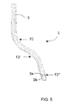
- the pedal 1 is subjected during the second stage to various consecutive stamping operations, in each of which is respectively exerted a load F2, F2', F2" on a front wall 3a of the profile 3, said respective load being transmitted to the respective front wall 2a of the retainer member 2, and the pedal 1 adopting the geometric shape shown in Figure 5 .
- the loads F2, F2', F2" do not have to be equal, said loads being exerted on different points along the front wall 3b corresponding.
- the retainer member 2 shown in detail in Figures 3 and 8 , is flexible and substantially incompressible.
- the retainer member 2 is flexible in the direction of application of the loads F1, F1', F1", F2, F2' and F2"', adapting itself to the respective deformations of the side walls 3b or front walls 3a of the profile 3, side walls 3b or front walls 3a, where the corresponding load F1, F1', F1", F2, F2' and F2" is applied.
- the retainer member 2 is substantially incompressible, the distance between the side walls 3b and the front walls 3a respectively being substantially maintained.
- the retainer member 2 comprises a plurality of cross-profiles 4 arranged along the front walls 2a, substantially transversal to said front walls 2a.
- the profile 4 is a gap that passes substantially orthogonally through the side walls 2b.
- the gaps 4 are arranged spaced along the length of the retainer member 2.
- the gaps 4 allow the retainer member 2 to bend in the direction of application of the loads, allowing the profile 3, in particular the front walls 3a, to become deformed in said direction. Thanks to the incompressibility of said retainer member 2, deformations in other directions are prevented, in particular deformations of the side walls 3b of the profile 3 are prevented, the distance between both side walls 3b being kept constant.
- deformations in other directions are prevented, in particular deformations of the front walls 3a of the profile 3 are prevented, the distance between both front walls 3a being kept constant.
- the retainer member 2 is made of a plastic material, in particular high-density polyethylene.
- the material may be polypropylene, polystyrene, polyethylene, polyamide or even an elastomer that is flexible and substantially incompressible, while other materials that fulfil both requirements may also be used.
- the retainer member 2 also comprises holes 10 that are arranged longitudinally spaced out, said holes 10 passing through the side walls 2b of the retainer member 2.
- the holes 10 lighten the weight of the retainer member 2 as well as making said retainer member 2 flexible. In the embodiment shown, some holes 10 are connected to the corresponding gaps 4, thereby increasing the flexibility of the retainer member 2 in the area.
- the retainer member 2 may not comprise the gaps 4 and the holes 10, as long as the material used is sufficiently flexible, incompressible and is not too heavy.
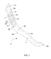
- FIGS 6 and 7 show a motor vehicle pedal 1 manufactured by means of a manufacturing method according to the invention.
- the pedal 1 comprises a single retainer member 2, while in other embodiments not shown in the figures the pedal 1 may comprise a plurality of retainer members 2 arranged adjacent to each other inside the profile 3.
- the profile 3 comprises holes 11 for the passage of an axis of rotation of the pedal 1, not shown in the figures.
- said holes may be formed in the profile 3 at a later stage.
- the pedal 1 according to the invention may be a brake pedal, accelerator or even a clutch.
Landscapes
- Engineering & Computer Science (AREA)
- Mechanical Engineering (AREA)
- Manufacturing & Machinery (AREA)
- Physics & Mathematics (AREA)
- General Physics & Mathematics (AREA)
- Automation & Control Theory (AREA)
- Transportation (AREA)
- Mechanical Control Devices (AREA)
- Auxiliary Drives, Propulsion Controls, And Safety Devices (AREA)
- Arrangement And Mounting Of Devices That Control Transmission Of Motive Force (AREA)
Abstract
Description
- This invention relates to a method for manufacturing a pedal for a motor vehicle and a pedal obtained according to the manufacturing method.
- Known motor vehicle pedals have irregular shapes in more than one direction, their manufacture being complex. For their fabrication, on many occasions the process starts with a closed contour obtained by different techniques and subsequently subjected to bending, curving and/or cutting operations.
- Document
ES2269332T3 - One problem associated with these manufacturing methods is the generation of internal deformations inside the hollow pipe or closed hollow profile when they are subjected to forming operations.
- The object of the invention is to provide a method for manufacturing a pedal for a motor vehicle, as defined in the claims.
- The manufacturing method comprises at least one stamping stage. The pedal comprises a hollow profile inside which is inserted at least one retainer member that is flexible and substantially incompressible. The retainer member is inserted inside the profile of the pedal before the corresponding stamping stage is performed.
- As a result, during the stamping stage internal deformations caused by the bending of the profile of the pedal towards its interior are prevented from occurring. Said internal deformations are generated, in particular, on pedals with very pronounced curvatures, defined with small radii, or on pedals having excessive width. As well as not being aesthetic, internal deformations are harmful to the subsequent mechanical behaviour of the pedal and may even make the pedal impossible to manufacture.
- The retainer member is flexible so that it may adapt to the deformations of the profile of the pedal in the direction of stamping, allowing stamping to be carried out in a simple manner. In addition, said retainer member is substantially incompressible, in order to prevent deformations of the profile occurring in other directions, in particular deformations towards the inside of the profile during said stamping.
- These and other advantages and characteristics of the invention will be made evident in the light of the drawings and the detailed description thereof.
-
-
Figure 1 shows an exploded view of the pedal, which comprises a profile and a retainer member, prior to being formed. -
Figure 2 shows a sectional view of the pedal shown inFigure 1 , with the retainer member inserted inside the profile, prior to being formed. -
Figure 3 shows another view in perspective of the retainer member shown inFigure 1 . -
Figure 4 shows a side view of the pedal shown inFigure 1 , after a first forming stage. -
Figure 5 shows a front view of the pedal shown inFigure 1 , after a second forming stage. -
Figure 6 shows a view in perspective of the pedal shown inFigure 1 , after the pedal has been formed. -
Figure 7 shows a partially sectional view of the pedal shown inFigure 1 , after the pedal has been formed. -
Figure 8 shows a view in perspective of the retainer member shown inFigure 1 , after the pedal has been formed. -
Figures 1, 2 and4 to 6 schematically show a process for manufacturing apedal 1 adapted to a motor vehicle, according to the invention. Thepedal 1 obtained according to the manufacturing method of the invention, described below, comprises a metal hollow profile3, with a substantially rectangular cross-profile, and at least oneretainer member 2 housed inside theprofile 3, saidretainer member 2 being arranged trapped inside theprofile 3. The stampedprofile 3 obtained does not include internal deformations. - In order to obtain the
pedal 1, the process starts with ahollow profile 3, with a substantially prismatic shape, inside which is inserted aretainer member 2, as shown inFigures 1 and 2 . Theretainer member 2 has a shape adapted to the internal shape of theprofile 3, the shape of the substantiallyprismatic profile 3 being defined byside walls 3b substantially parallel to each other andfront walls 3a. As a result, when saidretainer member 2 is inserted inside theprofile 3 it is retained inside theprofile 3 by the shape of theprofile 3 itself. - In the embodiment shown in the figures, the
retainer member 2, with a substantially quadrilateral cross-profile, comprisesside walls 2b, substantially parallel to each other, andfront walls 2a that longitudinally connect theside walls 2b to each other. Theside walls 2b and thefront walls 2a of theretainer member 2 are arranged facing each other, inside theprofile 3, respectively to theside walls 3b and thefront walls 3a of theprofile 3. - In other embodiments, not shown in the figures, both the
profile 3 and theretainer member 2 may have a substantially pyramidal shape, in which therespective side walls - Once the
retainer member 2 is housed inside theprofile 3, thepedal 1 is subjected to a first stamping stage. In said first stage, thepedal 1 is subjected to at least one load F1, F1', F1" on at least oneside wall 3b of theprofile 3, in a direction substantially orthogonal to saidside wall 3b. In the embodiment shown in the figures, thepedal 1 is subjected during the first stage to various consecutive stamping operations, in each of which a load F1, F1', F1" is exerted on thecorresponding side wall 3b of theprofile 3, said respective load being transmitted to therespective side wall 2b of theretainer member 2, and thepedal 1 adopting the geometric shape shown inFigure 4 . The loads F1, F1', F1" do not have to be equal, said loads being exerted on different points along thecorresponding side wall 3b. - After the first stamping stage, the
pedal 1 is subjected to a second stamping stage. In the second stage thepedal 1 is subjected to at least one load F2, F2', F2" on at least onefront wall 3a of theprofile 3, in a direction substantially orthogonal to saidfront wall 3a. In the embodiment shown in the figures, thepedal 1 is subjected during the second stage to various consecutive stamping operations, in each of which is respectively exerted a load F2, F2', F2" on afront wall 3a of theprofile 3, said respective load being transmitted to the respectivefront wall 2a of theretainer member 2, and thepedal 1 adopting the geometric shape shown inFigure 5 . The loads F2, F2', F2" do not have to be equal, said loads being exerted on different points along thefront wall 3b corresponding. - The
retainer member 2, shown in detail inFigures 3 and8 , is flexible and substantially incompressible. As a result, theretainer member 2 is flexible in the direction of application of the loads F1, F1', F1", F2, F2' and F2"', adapting itself to the respective deformations of theside walls 3b orfront walls 3a of theprofile 3,side walls 3b orfront walls 3a, where the corresponding load F1, F1', F1", F2, F2' and F2" is applied. At the same time, theretainer member 2 is substantially incompressible, the distance between theside walls 3b and thefront walls 3a respectively being substantially maintained. For this purpose, theretainer member 2 comprises a plurality ofcross-profiles 4 arranged along thefront walls 2a, substantially transversal to saidfront walls 2a. In the embodiment shown in the figures, theprofile 4 is a gap that passes substantially orthogonally through theside walls 2b. Thegaps 4 are arranged spaced along the length of theretainer member 2. - As a result, when the loads F1, F1' and F1" are applied on the
respective side walls 3b of theprofile 3, thegaps 4 allow theretainer member 2 to bend in the direction of application of the loads, allowing theprofile 3, in particular thefront walls 3a, to become deformed in said direction. Thanks to the incompressibility of saidretainer member 2, deformations in other directions are prevented, in particular deformations of theside walls 3b of theprofile 3 are prevented, the distance between bothside walls 3b being kept constant. - In addition, when the loads F2, F2' and F2" are applied on the respective
front walls 3a of theprofile 3, thegaps 4, which also pass through theside walls 2b of theretainer member 2, allow saidretainer member 2 to bend in the direction of application of the loads, allowing theprofile 3, in particular theside walls 3b, to become deformed in said direction. As in the previous stage, thanks to the incompressibility of saidretainer member 2, deformations in other directions are prevented, in particular deformations of thefront walls 3a of theprofile 3 are prevented, the distance between bothfront walls 3a being kept constant. - As a result, a stamped profile of a pedal is obtained and which does not include internal deformations.
- In the embodiment shown the
retainer member 2 is made of a plastic material, in particular high-density polyethylene. In other embodiments not shown in the figures, the material may be polypropylene, polystyrene, polyethylene, polyamide or even an elastomer that is flexible and substantially incompressible, while other materials that fulfil both requirements may also be used. - Additionally, the
retainer member 2 also comprisesholes 10 that are arranged longitudinally spaced out, saidholes 10 passing through theside walls 2b of theretainer member 2. Theholes 10 lighten the weight of theretainer member 2 as well as making saidretainer member 2 flexible. In the embodiment shown, someholes 10 are connected to thecorresponding gaps 4, thereby increasing the flexibility of theretainer member 2 in the area. - In other embodiments not shown in the figures, the
retainer member 2 may not comprise thegaps 4 and theholes 10, as long as the material used is sufficiently flexible, incompressible and is not too heavy. -
Figures 6 and7 show amotor vehicle pedal 1 manufactured by means of a manufacturing method according to the invention. In the embodiment shown in the figures, thepedal 1 comprises asingle retainer member 2, while in other embodiments not shown in the figures thepedal 1 may comprise a plurality ofretainer members 2 arranged adjacent to each other inside theprofile 3. - The description does not include specific details of the bending or stamping stages or the machines and tools on which said stages are performed, as they are known in the prior art and are not considered necessary for the correct understanding of the invention.
- In addition, in the embodiment shown in the figures the
profile 3 comprisesholes 11 for the passage of an axis of rotation of thepedal 1, not shown in the figures. In other embodiments, said holes may be formed in theprofile 3 at a later stage. - The
pedal 1 according to the invention may be a brake pedal, accelerator or even a clutch.
Claims (15)
- Method for manufacturing a pedal for a motor vehicle, the pedal (1) comprising a hollow profile (3) and the method comprising at least one stamping stage of said profile (3), characterised in that at least one retainer member (2) is inserted inside the profile (3) of the pedal (1) before the stamping stage, said retainer member (2) being flexible and substantially incompressible.
- Method for manufacturing a pedal according to the preceding claim, wherein the retainer member (2) has a shape adapted to the interior of the profile (3).
- Method for manufacturing a pedal according to the preceding claim, wherein the profile (3) has a substantially prismatic shape, defined by side walls (3b) substantially parallel to each other and front walls (3a).
- Method for manufacturing a pedal according to the preceding claim, wherein once the retainer member (2) has been inserted inside the profile (3), the profile (3) is subjected to a first stamping stage, with at least one load (F1,F1',F1") being applied on the corresponding front wall (3a) of the profile (3), in a direction substantially orthogonal to said front wall (3a) of the profile (3), the profile (3) and the retainer member (2) being substantially deformed in said direction.
- Method for manufacturing a pedal according to the preceding claim, wherein the profile (3) is subjected to various consecutive loads (F1,F1',F1") along the front walls (3a) of the profile (3).
- Method for the manufacture of a pedal according to claims 4 or 5, wherein the profile (3) is subsequently subjected to a second stamping stage, at least one load (F2,F2',F2") being applied on the corresponding side wall (3b) of the profile (3), in a direction substantially orthogonal to said side wall (3b) of the profile (3), the profile (3) and the retainer member (2) being substantially deformed in said direction.
- Method for manufacturing a pedal according to the preceding claim, wherein the profile (3) is subjected to various consecutive loads (F2,F2',F2") along the side walls (3b) of the profile (3).
- Pedal for a motor vehicle obtained according to the manufacturing method according to any of the preceding claims, comprising the profile (3) and at least one retainer member (2) trapped inside the profile (3).
- Pedal according to the preceding claim, wherein the retainer member (2) has a substantially prismatic shape, defined by side walls (2b) substantially parallel to each other, and front walls (2a) that longitudinally connect the side walls (2b) to each other.
- Pedal according to the preceding claim, wherein the retainer member (2) comprises at least one profile (4), arranged on the front wall (2a), which passes through the side walls (2b).
- Pedal according to the preceding claim, wherein the retainer member (2) comprises a plurality of cross-profiles (4) arranged spaced along the front walls (2a), which pass through the side walls (2b).
- Pedal according to claims 10 or 11, wherein the profile (4) is a gap.
- Pedal according to any of claims 8 to 12, wherein the retainer member (2) is made of a plastic material.
- Pedal according to the preceding claim, wherein the retainer member (2) is made of high-density polyethylene.
- Pedal according to any of claims 8 to 14, wherein the profile (3) comprises a plurality of retainer members (2) arranged adjacent to each other inside the profile (3).
Applications Claiming Priority (1)
| Application Number | Priority Date | Filing Date | Title |
|---|---|---|---|
| ES201131700A ES2405154B1 (en) | 2011-10-21 | 2011-10-21 | Method of manufacturing a pedal for a motor vehicle, and pedal obtained according to the manufacturing method |
Publications (3)
| Publication Number | Publication Date |
|---|---|
| EP2583765A2 true EP2583765A2 (en) | 2013-04-24 |
| EP2583765A3 EP2583765A3 (en) | 2014-01-22 |
| EP2583765B1 EP2583765B1 (en) | 2017-11-08 |
Family
ID=47115696
Family Applications (1)
| Application Number | Title | Priority Date | Filing Date |
|---|---|---|---|
| EP12382380.9A Active EP2583765B1 (en) | 2011-10-21 | 2012-10-01 | Method for manufacturing a pedal for a motor vehicle, and pedal obtained according to the manufacturing method |
Country Status (5)
| Country | Link |
|---|---|
| US (2) | US8695393B2 (en) |
| EP (1) | EP2583765B1 (en) |
| CN (1) | CN103100608A (en) |
| BR (1) | BR102012025964A2 (en) |
| ES (1) | ES2405154B1 (en) |
Cited By (1)
| Publication number | Priority date | Publication date | Assignee | Title |
|---|---|---|---|---|
| EP3535500B1 (en) * | 2016-12-05 | 2023-05-17 | Vibracoustic SE | Core, bearing comprising such a core, and method for producing the bearing |
Families Citing this family (4)
| Publication number | Priority date | Publication date | Assignee | Title |
|---|---|---|---|---|
| CN104259277B (en) * | 2014-09-22 | 2017-06-30 | 倪慨宇 | A kind of plastic constraint component for bending thin-wall section |
| CN107160115A (en) * | 2017-07-20 | 2017-09-15 | 奇瑞汽车股份有限公司 | A kind of processing technology of hollow brake pedal arm |
| US10538263B2 (en) * | 2018-06-18 | 2020-01-21 | Steering Solutions Ip Holding Corporation | Controlled energy absorbing rake adjustment lever |
| JP7509732B2 (en) * | 2021-10-12 | 2024-07-02 | 豊田鉄工株式会社 | Vehicle pedals |
Citations (1)
| Publication number | Priority date | Publication date | Assignee | Title |
|---|---|---|---|---|
| ES2269332T3 (en) | 2000-03-01 | 2007-04-01 | Tubsa Automocion, S.L. | PROCEDURE FOR MANUFACTURING A BRAKE PEDAL FOR MOTOR VEHICLES. |
Family Cites Families (20)
| Publication number | Priority date | Publication date | Assignee | Title |
|---|---|---|---|---|
| US3572083A (en) * | 1968-08-19 | 1971-03-23 | John G Schmitt | Articulated flexible wave guide bending and sizing mandrel for h plane |
| US3744340A (en) | 1972-04-10 | 1973-07-10 | Gen Motors Corp | Stamped brake pedal |
| US3841138A (en) * | 1972-10-25 | 1974-10-15 | Reynolds Metals Co | Apparatus and method for forming an elongated tubular member |
| US4352285A (en) * | 1979-09-06 | 1982-10-05 | Crutcher Resources Corporation | Hydraulic wedge mandrel |
| FR2523742A1 (en) | 1982-03-18 | 1983-09-23 | Peugeot Cycles | Rigid brake pedal for motor vehicle - comprises tube bent and pressed to shape for attachment of pedal plate and linkage |
| US4569256A (en) * | 1984-09-11 | 1986-02-11 | Edward Pepper | Method of making a seamless punch |
| US4598457A (en) | 1985-08-26 | 1986-07-08 | Allied Corporation | Method of constructing a brake pedal |
| US4744233A (en) * | 1986-07-14 | 1988-05-17 | Ap Industries, Inc. | Apparatus for bending rectangular tubes |
| US5070717A (en) | 1991-01-22 | 1991-12-10 | General Motors Corporation | Method of forming a tubular member with flange |
| US5131254A (en) * | 1991-01-29 | 1992-07-21 | Whitefab, Inc | Apparatus for bending beams |
| US5435205A (en) | 1993-06-24 | 1995-07-25 | Aluminum Company Of America | Pedal mechanism and method for forming the same |
| DE4442122A1 (en) | 1994-11-26 | 1996-05-30 | Porsche Ag | One-piece pedal |
| CA2236179C (en) | 1997-04-30 | 2005-09-20 | Ventra Group, Inc. | Pedal arm assembly |
| GB2325511B (en) | 1997-05-22 | 2000-11-22 | Draftex Ind Ltd | Control pedal |
| FR2821684B1 (en) | 2001-03-05 | 2003-05-30 | Peugeot Citroen Automobiles Sa | CONTROL PEDAL, ESPECIALLY USEFUL FOR A BRAKE |
| US20050072263A1 (en) * | 2003-10-06 | 2005-04-07 | Gibson Jeffrey G. | Automotive foot pedal and method of manufacture |
| JP4907080B2 (en) * | 2004-12-27 | 2012-03-28 | 住友金属工業株式会社 | Method for tensile bending of deformed pipe and processed automotive parts |
| WO2006106622A1 (en) | 2005-03-30 | 2006-10-12 | Infec Corporation | Device and method for elliptically processing metal tube and metal tube product |
| JP5474398B2 (en) | 2009-04-17 | 2014-04-16 | 株式会社ヨロズ | Arm parts for vehicles and manufacturing method thereof |
| EP2370241A1 (en) * | 2009-06-15 | 2011-10-05 | Trelleborg Reims SAS | Method for manufacturing hybrid levers and pedals and implementation thereof in automobiles |
-
2011
- 2011-10-21 ES ES201131700A patent/ES2405154B1/en not_active Expired - Fee Related
-
2012
- 2012-10-01 EP EP12382380.9A patent/EP2583765B1/en active Active
- 2012-10-10 BR BR102012025964-8A patent/BR102012025964A2/en not_active IP Right Cessation
- 2012-10-18 CN CN2012103962447A patent/CN103100608A/en active Pending
- 2012-10-19 US US13/656,343 patent/US8695393B2/en active Active
- 2012-10-19 US US13/656,296 patent/US8833129B2/en active Active
Patent Citations (1)
| Publication number | Priority date | Publication date | Assignee | Title |
|---|---|---|---|---|
| ES2269332T3 (en) | 2000-03-01 | 2007-04-01 | Tubsa Automocion, S.L. | PROCEDURE FOR MANUFACTURING A BRAKE PEDAL FOR MOTOR VEHICLES. |
Cited By (1)
| Publication number | Priority date | Publication date | Assignee | Title |
|---|---|---|---|---|
| EP3535500B1 (en) * | 2016-12-05 | 2023-05-17 | Vibracoustic SE | Core, bearing comprising such a core, and method for producing the bearing |
Also Published As
| Publication number | Publication date |
|---|---|
| CN103100608A (en) | 2013-05-15 |
| US8695393B2 (en) | 2014-04-15 |
| US8833129B2 (en) | 2014-09-16 |
| EP2583765B1 (en) | 2017-11-08 |
| ES2405154R1 (en) | 2013-10-07 |
| EP2583765A3 (en) | 2014-01-22 |
| US20130098133A1 (en) | 2013-04-25 |
| ES2405154B1 (en) | 2014-08-04 |
| ES2405154A2 (en) | 2013-05-30 |
| US20130101769A1 (en) | 2013-04-25 |
| BR102012025964A2 (en) | 2013-11-05 |
Similar Documents
| Publication | Publication Date | Title |
|---|---|---|
| EP2583765A2 (en) | Method for manufacturing a pedal for a motor vehicle, and pedal obtained according to the manufacturing method | |
| US9040134B2 (en) | Process of producing profiles whose cross-section is variable in the longitudinal direction | |
| US8567839B2 (en) | Multi-part equipment piece for a vehicle and connecting method | |
| US20180281041A1 (en) | Method and system for flanging a metal piece | |
| EP3124332B1 (en) | Method for manufacturing vehicle structural member | |
| US10596870B2 (en) | Vehicular arm component manufacturing method and vehicular arm component | |
| US9027989B1 (en) | Extruded body component with notched flange to reduce strain in bending | |
| EP3069964A2 (en) | Underbody manufacturing method and vehicle underbody | |
| CN104279215A (en) | Alignment arrangement for mated components and method | |
| DE112011102600T5 (en) | Bumper system with frictionally attached energy absorber and method | |
| KR20110045311A (en) | Steering Joint for Automobile and Manufacturing Method | |
| JP2015505276A (en) | Apparatus and method for deep-drawing shell-shaped parts incorporating upper and frame cutting | |
| US20180128370A1 (en) | Metal element for continuously variable transmission and method of manufacturing metal element for continuously variable transmission | |
| CN106275085B (en) | Vehicle and carriage assembly for vehicle | |
| US20170304886A1 (en) | Forming method and die assembly using a bead with a step | |
| US20120131848A1 (en) | Vineyard Stake | |
| JP6094699B2 (en) | PRESS-MOLDED PRODUCTION METHOD, PRESS-MOLDED PRODUCT, AND PRESS DEVICE | |
| CN107921850B (en) | Pressed reinforced beams capable of programmed deformation | |
| KR20160032223A (en) | Method for manufacturing curved component having polygonal closed-cross-sectional structure and curved component having polygonal closed-cross-sectional structure and manufactured using said method | |
| JP5910261B2 (en) | Manufacturing method and manufacturing apparatus for link for power transmission chain | |
| DE102010034416A1 (en) | Pedal for motor car, has pedal main portion that is formed as extruded profile, and is viewed as extruded hollow portion in longitudinal direction | |
| CN110038975B (en) | Method for producing a curved torsion profile and torsion profile | |
| WO2017215694A3 (en) | Cross-hole punching of planetary gear pins and planetary gear pin having double-conical fluid-guiding through-openings | |
| US20180172061A1 (en) | Method of manufacturing washer and washer | |
| EP2921927A2 (en) | Control pedal for vehicle and manufacturing method thereof |
Legal Events
| Date | Code | Title | Description |
|---|---|---|---|
| PUAI | Public reference made under article 153(3) epc to a published international application that has entered the european phase |
Free format text: ORIGINAL CODE: 0009012 |
|
| AK | Designated contracting states |
Kind code of ref document: A2 Designated state(s): AL AT BE BG CH CY CZ DE DK EE ES FI FR GB GR HR HU IE IS IT LI LT LU LV MC MK MT NL NO PL PT RO RS SE SI SK SM TR |
|
| AX | Request for extension of the european patent |
Extension state: BA ME |
|
| PUAL | Search report despatched |
Free format text: ORIGINAL CODE: 0009013 |
|
| AK | Designated contracting states |
Kind code of ref document: A3 Designated state(s): AL AT BE BG CH CY CZ DE DK EE ES FI FR GB GR HR HU IE IS IT LI LT LU LV MC MK MT NL NO PL PT RO RS SE SI SK SM TR |
|
| AX | Request for extension of the european patent |
Extension state: BA ME |
|
| RIC1 | Information provided on ipc code assigned before grant |
Ipc: G05G 1/50 20080401ALI20131219BHEP Ipc: B60T 7/06 20060101ALI20131219BHEP Ipc: B21D 9/01 20060101AFI20131219BHEP Ipc: B21D 22/12 20060101ALI20131219BHEP Ipc: B21D 53/88 20060101ALI20131219BHEP |
|
| 17P | Request for examination filed |
Effective date: 20140722 |
|
| RBV | Designated contracting states (corrected) |
Designated state(s): AL AT BE BG CH CY CZ DE DK EE ES FI FR GB GR HR HU IE IS IT LI LT LU LV MC MK MT NL NO PL PT RO RS SE SI SK SM TR |
|
| 17Q | First examination report despatched |
Effective date: 20150121 |
|
| GRAP | Despatch of communication of intention to grant a patent |
Free format text: ORIGINAL CODE: EPIDOSNIGR1 |
|
| INTG | Intention to grant announced |
Effective date: 20170704 |
|
| GRAS | Grant fee paid |
Free format text: ORIGINAL CODE: EPIDOSNIGR3 |
|
| GRAA | (expected) grant |
Free format text: ORIGINAL CODE: 0009210 |
|
| AK | Designated contracting states |
Kind code of ref document: B1 Designated state(s): AL AT BE BG CH CY CZ DE DK EE ES FI FR GB GR HR HU IE IS IT LI LT LU LV MC MK MT NL NO PL PT RO RS SE SI SK SM TR |
|
| REG | Reference to a national code |
Ref country code: GB Ref legal event code: FG4D |
|
| REG | Reference to a national code |
Ref country code: CH Ref legal event code: EP Ref country code: AT Ref legal event code: REF Ref document number: 943662 Country of ref document: AT Kind code of ref document: T Effective date: 20171115 |
|
| REG | Reference to a national code |
Ref country code: IE Ref legal event code: FG4D |
|
| REG | Reference to a national code |
Ref country code: DE Ref legal event code: R096 Ref document number: 602012039453 Country of ref document: DE |
|
| REG | Reference to a national code |
Ref country code: NL Ref legal event code: MP Effective date: 20171108 |
|
| REG | Reference to a national code |
Ref country code: LT Ref legal event code: MG4D |
|
| REG | Reference to a national code |
Ref country code: AT Ref legal event code: MK05 Ref document number: 943662 Country of ref document: AT Kind code of ref document: T Effective date: 20171108 |
|
| PG25 | Lapsed in a contracting state [announced via postgrant information from national office to epo] |
Ref country code: LT Free format text: LAPSE BECAUSE OF FAILURE TO SUBMIT A TRANSLATION OF THE DESCRIPTION OR TO PAY THE FEE WITHIN THE PRESCRIBED TIME-LIMIT Effective date: 20171108 Ref country code: SE Free format text: LAPSE BECAUSE OF FAILURE TO SUBMIT A TRANSLATION OF THE DESCRIPTION OR TO PAY THE FEE WITHIN THE PRESCRIBED TIME-LIMIT Effective date: 20171108 Ref country code: NO Free format text: LAPSE BECAUSE OF FAILURE TO SUBMIT A TRANSLATION OF THE DESCRIPTION OR TO PAY THE FEE WITHIN THE PRESCRIBED TIME-LIMIT Effective date: 20180208 Ref country code: NL Free format text: LAPSE BECAUSE OF FAILURE TO SUBMIT A TRANSLATION OF THE DESCRIPTION OR TO PAY THE FEE WITHIN THE PRESCRIBED TIME-LIMIT Effective date: 20171108 Ref country code: FI Free format text: LAPSE BECAUSE OF FAILURE TO SUBMIT A TRANSLATION OF THE DESCRIPTION OR TO PAY THE FEE WITHIN THE PRESCRIBED TIME-LIMIT Effective date: 20171108 Ref country code: ES Free format text: LAPSE BECAUSE OF FAILURE TO SUBMIT A TRANSLATION OF THE DESCRIPTION OR TO PAY THE FEE WITHIN THE PRESCRIBED TIME-LIMIT Effective date: 20171108 |
|
| PG25 | Lapsed in a contracting state [announced via postgrant information from national office to epo] |
Ref country code: RS Free format text: LAPSE BECAUSE OF FAILURE TO SUBMIT A TRANSLATION OF THE DESCRIPTION OR TO PAY THE FEE WITHIN THE PRESCRIBED TIME-LIMIT Effective date: 20171108 Ref country code: IS Free format text: LAPSE BECAUSE OF FAILURE TO SUBMIT A TRANSLATION OF THE DESCRIPTION OR TO PAY THE FEE WITHIN THE PRESCRIBED TIME-LIMIT Effective date: 20180308 Ref country code: HR Free format text: LAPSE BECAUSE OF FAILURE TO SUBMIT A TRANSLATION OF THE DESCRIPTION OR TO PAY THE FEE WITHIN THE PRESCRIBED TIME-LIMIT Effective date: 20171108 Ref country code: GR Free format text: LAPSE BECAUSE OF FAILURE TO SUBMIT A TRANSLATION OF THE DESCRIPTION OR TO PAY THE FEE WITHIN THE PRESCRIBED TIME-LIMIT Effective date: 20180209 Ref country code: LV Free format text: LAPSE BECAUSE OF FAILURE TO SUBMIT A TRANSLATION OF THE DESCRIPTION OR TO PAY THE FEE WITHIN THE PRESCRIBED TIME-LIMIT Effective date: 20171108 Ref country code: BG Free format text: LAPSE BECAUSE OF FAILURE TO SUBMIT A TRANSLATION OF THE DESCRIPTION OR TO PAY THE FEE WITHIN THE PRESCRIBED TIME-LIMIT Effective date: 20180208 Ref country code: AT Free format text: LAPSE BECAUSE OF FAILURE TO SUBMIT A TRANSLATION OF THE DESCRIPTION OR TO PAY THE FEE WITHIN THE PRESCRIBED TIME-LIMIT Effective date: 20171108 |
|
| PG25 | Lapsed in a contracting state [announced via postgrant information from national office to epo] |
Ref country code: CZ Free format text: LAPSE BECAUSE OF FAILURE TO SUBMIT A TRANSLATION OF THE DESCRIPTION OR TO PAY THE FEE WITHIN THE PRESCRIBED TIME-LIMIT Effective date: 20171108 Ref country code: EE Free format text: LAPSE BECAUSE OF FAILURE TO SUBMIT A TRANSLATION OF THE DESCRIPTION OR TO PAY THE FEE WITHIN THE PRESCRIBED TIME-LIMIT Effective date: 20171108 Ref country code: CY Free format text: LAPSE BECAUSE OF FAILURE TO SUBMIT A TRANSLATION OF THE DESCRIPTION OR TO PAY THE FEE WITHIN THE PRESCRIBED TIME-LIMIT Effective date: 20171108 Ref country code: SK Free format text: LAPSE BECAUSE OF FAILURE TO SUBMIT A TRANSLATION OF THE DESCRIPTION OR TO PAY THE FEE WITHIN THE PRESCRIBED TIME-LIMIT Effective date: 20171108 Ref country code: DK Free format text: LAPSE BECAUSE OF FAILURE TO SUBMIT A TRANSLATION OF THE DESCRIPTION OR TO PAY THE FEE WITHIN THE PRESCRIBED TIME-LIMIT Effective date: 20171108 |
|
| REG | Reference to a national code |
Ref country code: DE Ref legal event code: R097 Ref document number: 602012039453 Country of ref document: DE |
|
| PG25 | Lapsed in a contracting state [announced via postgrant information from national office to epo] |
Ref country code: RO Free format text: LAPSE BECAUSE OF FAILURE TO SUBMIT A TRANSLATION OF THE DESCRIPTION OR TO PAY THE FEE WITHIN THE PRESCRIBED TIME-LIMIT Effective date: 20171108 Ref country code: PL Free format text: LAPSE BECAUSE OF FAILURE TO SUBMIT A TRANSLATION OF THE DESCRIPTION OR TO PAY THE FEE WITHIN THE PRESCRIBED TIME-LIMIT Effective date: 20171108 Ref country code: SM Free format text: LAPSE BECAUSE OF FAILURE TO SUBMIT A TRANSLATION OF THE DESCRIPTION OR TO PAY THE FEE WITHIN THE PRESCRIBED TIME-LIMIT Effective date: 20171108 Ref country code: IT Free format text: LAPSE BECAUSE OF FAILURE TO SUBMIT A TRANSLATION OF THE DESCRIPTION OR TO PAY THE FEE WITHIN THE PRESCRIBED TIME-LIMIT Effective date: 20171108 |
|
| PLBE | No opposition filed within time limit |
Free format text: ORIGINAL CODE: 0009261 |
|
| STAA | Information on the status of an ep patent application or granted ep patent |
Free format text: STATUS: NO OPPOSITION FILED WITHIN TIME LIMIT |
|
| 26N | No opposition filed |
Effective date: 20180809 |
|
| PG25 | Lapsed in a contracting state [announced via postgrant information from national office to epo] |
Ref country code: SI Free format text: LAPSE BECAUSE OF FAILURE TO SUBMIT A TRANSLATION OF THE DESCRIPTION OR TO PAY THE FEE WITHIN THE PRESCRIBED TIME-LIMIT Effective date: 20171108 |
|
| REG | Reference to a national code |
Ref country code: CH Ref legal event code: PK Free format text: BERICHTIGUNGEN |
|
| RIC2 | Information provided on ipc code assigned after grant |
Ipc: B21D 53/88 20060101ALI20131219BHEP Ipc: B21D 22/12 20060101ALI20131219BHEP Ipc: B60T 7/06 20060101ALI20131219BHEP Ipc: B21D 9/01 20060101AFI20131219BHEP Ipc: G05G 1/50 20080401ALI20131219BHEP |
|
| REG | Reference to a national code |
Ref country code: CH Ref legal event code: PL |
|
| GBPC | Gb: european patent ceased through non-payment of renewal fee |
Effective date: 20181001 |
|
| REG | Reference to a national code |
Ref country code: BE Ref legal event code: MM Effective date: 20181031 |
|
| PG25 | Lapsed in a contracting state [announced via postgrant information from national office to epo] |
Ref country code: MC Free format text: LAPSE BECAUSE OF FAILURE TO SUBMIT A TRANSLATION OF THE DESCRIPTION OR TO PAY THE FEE WITHIN THE PRESCRIBED TIME-LIMIT Effective date: 20171108 Ref country code: LU Free format text: LAPSE BECAUSE OF NON-PAYMENT OF DUE FEES Effective date: 20181001 |
|
| REG | Reference to a national code |
Ref country code: IE Ref legal event code: MM4A |
|
| PG25 | Lapsed in a contracting state [announced via postgrant information from national office to epo] |
Ref country code: BE Free format text: LAPSE BECAUSE OF NON-PAYMENT OF DUE FEES Effective date: 20181031 Ref country code: LI Free format text: LAPSE BECAUSE OF NON-PAYMENT OF DUE FEES Effective date: 20181031 Ref country code: CH Free format text: LAPSE BECAUSE OF NON-PAYMENT OF DUE FEES Effective date: 20181031 |
|
| PG25 | Lapsed in a contracting state [announced via postgrant information from national office to epo] |
Ref country code: FR Free format text: LAPSE BECAUSE OF NON-PAYMENT OF DUE FEES Effective date: 20181031 Ref country code: IE Free format text: LAPSE BECAUSE OF NON-PAYMENT OF DUE FEES Effective date: 20181001 Ref country code: GB Free format text: LAPSE BECAUSE OF NON-PAYMENT OF DUE FEES Effective date: 20181001 |
|
| PG25 | Lapsed in a contracting state [announced via postgrant information from national office to epo] |
Ref country code: MT Free format text: LAPSE BECAUSE OF NON-PAYMENT OF DUE FEES Effective date: 20181001 |
|
| PG25 | Lapsed in a contracting state [announced via postgrant information from national office to epo] |
Ref country code: TR Free format text: LAPSE BECAUSE OF FAILURE TO SUBMIT A TRANSLATION OF THE DESCRIPTION OR TO PAY THE FEE WITHIN THE PRESCRIBED TIME-LIMIT Effective date: 20171108 |
|
| PG25 | Lapsed in a contracting state [announced via postgrant information from national office to epo] |
Ref country code: PT Free format text: LAPSE BECAUSE OF FAILURE TO SUBMIT A TRANSLATION OF THE DESCRIPTION OR TO PAY THE FEE WITHIN THE PRESCRIBED TIME-LIMIT Effective date: 20171108 |
|
| PG25 | Lapsed in a contracting state [announced via postgrant information from national office to epo] |
Ref country code: HU Free format text: LAPSE BECAUSE OF FAILURE TO SUBMIT A TRANSLATION OF THE DESCRIPTION OR TO PAY THE FEE WITHIN THE PRESCRIBED TIME-LIMIT; INVALID AB INITIO Effective date: 20121001 Ref country code: MK Free format text: LAPSE BECAUSE OF NON-PAYMENT OF DUE FEES Effective date: 20171108 |
|
| PG25 | Lapsed in a contracting state [announced via postgrant information from national office to epo] |
Ref country code: AL Free format text: LAPSE BECAUSE OF FAILURE TO SUBMIT A TRANSLATION OF THE DESCRIPTION OR TO PAY THE FEE WITHIN THE PRESCRIBED TIME-LIMIT Effective date: 20171108 |
|
| PGFP | Annual fee paid to national office [announced via postgrant information from national office to epo] |
Ref country code: DE Payment date: 20251029 Year of fee payment: 14 |