EP2583634A1 - Head immobilization device - Google Patents
Head immobilization device Download PDFInfo
- Publication number
- EP2583634A1 EP2583634A1 EP11008466.2A EP11008466A EP2583634A1 EP 2583634 A1 EP2583634 A1 EP 2583634A1 EP 11008466 A EP11008466 A EP 11008466A EP 2583634 A1 EP2583634 A1 EP 2583634A1
- Authority
- EP
- European Patent Office
- Prior art keywords
- head
- immobilization device
- open frame
- base
- fixture
- Prior art date
- Legal status (The legal status is an assumption and is not a legal conclusion. Google has not performed a legal analysis and makes no representation as to the accuracy of the status listed.)
- Granted
Links
Images


Classifications
-
- A—HUMAN NECESSITIES
- A61—MEDICAL OR VETERINARY SCIENCE; HYGIENE
- A61B—DIAGNOSIS; SURGERY; IDENTIFICATION
- A61B90/00—Instruments, implements or accessories specially adapted for surgery or diagnosis and not covered by any of the groups A61B1/00 - A61B50/00, e.g. for luxation treatment or for protecting wound edges
- A61B90/10—Instruments, implements or accessories specially adapted for surgery or diagnosis and not covered by any of the groups A61B1/00 - A61B50/00, e.g. for luxation treatment or for protecting wound edges for stereotaxic surgery, e.g. frame-based stereotaxis
- A61B90/14—Fixators for body parts, e.g. skull clamps; Constructional details of fixators, e.g. pins
- A61B90/18—Retaining sheets, e.g. immobilising masks made from a thermoplastic material
-
- A—HUMAN NECESSITIES
- A61—MEDICAL OR VETERINARY SCIENCE; HYGIENE
- A61B—DIAGNOSIS; SURGERY; IDENTIFICATION
- A61B90/00—Instruments, implements or accessories specially adapted for surgery or diagnosis and not covered by any of the groups A61B1/00 - A61B50/00, e.g. for luxation treatment or for protecting wound edges
- A61B90/10—Instruments, implements or accessories specially adapted for surgery or diagnosis and not covered by any of the groups A61B1/00 - A61B50/00, e.g. for luxation treatment or for protecting wound edges for stereotaxic surgery, e.g. frame-based stereotaxis
- A61B90/14—Fixators for body parts, e.g. skull clamps; Constructional details of fixators, e.g. pins
-
- A—HUMAN NECESSITIES
- A61—MEDICAL OR VETERINARY SCIENCE; HYGIENE
- A61B—DIAGNOSIS; SURGERY; IDENTIFICATION
- A61B6/00—Apparatus for radiation diagnosis, e.g. combined with radiation therapy equipment
- A61B6/04—Positioning of patients; Tiltable beds or the like
Landscapes
- Health & Medical Sciences (AREA)
- Surgery (AREA)
- Life Sciences & Earth Sciences (AREA)
- Biomedical Technology (AREA)
- Medical Informatics (AREA)
- Oral & Maxillofacial Surgery (AREA)
- Nuclear Medicine, Radiotherapy & Molecular Imaging (AREA)
- Engineering & Computer Science (AREA)
- Neurosurgery (AREA)
- Heart & Thoracic Surgery (AREA)
- Pathology (AREA)
- Molecular Biology (AREA)
- Animal Behavior & Ethology (AREA)
- General Health & Medical Sciences (AREA)
- Public Health (AREA)
- Veterinary Medicine (AREA)
- Radiation-Therapy Devices (AREA)
Abstract
Description
- The present invention relates to a head immobilization device used in the medical field having the features of the preamble part of
claim 1. - As a state of the art, head immobilization devices are known in the medical field to immobilize a patient's head during medical treatment, since it is necessary that the patient's head remains in the same position during the whole course of the medical treatment. The head immobilization device comprises a support plate structure and a head fixation element, whereby the head fixation element can be releasably connected to the support plate structure. During the medical treatment, the support plate structure serves as a head rest for the posterior head portion, while the anterior head portion is covered tightly with the head fixation element.
- The head fixation element comprises an open frame element with a mask element attached to it. The open frame element serves as a stabilization element for the mask element as well as an interface to the support plate structure. The mask element is fitted individually to the anterior head portion of a patient, e.g. by a molding process. As an example, the mask element can be molded directly to the anterior head portion by means of a net-like low temperature thermoplastic, with a working temperature between 65 - 72°C.
- The support plate structure incorporates a fixture mechanism comprising a base fixture element and leg fixture elements for fixing the base portion and the legs of the open frame element respectively. A levering mechanism with a spring load is provided in the support plate structure to actuate the base fixture element. When the head fixation element is attached or released, the operator levers the base fixture element with one hand into an opened state by applying a manual force on the levering mechanism against the spring load. The head fixation element can then be removed or attached with the other hand of the operator.
- It has been shown, that the levering mechanism is complex during attachment and release operation. Thereby discomfort for the patient is caused.
- It is the object of the invention to provide a more simplified fixing mechanism, which can be handled more easily.
- The present invention provides a head immobilization device for use in the medical field, comprising:
- The object is met with a device, having the features of the preamble part of
claim 1, and being characterized in that - the at least two leg fixture elements are designed to cooperate with the end portions of the legs such as to bias the head fixation element in the direction of the at least one base fixture element.
- The attachment operation of the present invention is easier, since therefore the end portions of the open frame element can be inserted into the at least two leg fixture elements and can be forced against spring-like elements within the at least two fixture elements. With a single hand or both hands on the open frame element, the open frame element can be latched into the at least one base fixture element. The release operation is easier, since therefore the open frame element can be unlatched from the at least one base fixture element by forcing the open frame element into the direction of the at least two leg fixture elements with a single or both hands and by applying a lifting force to remove the head fixation element. Both attachment and release operations can be carried out with a single hand or with both hands on the open frame element, thus providing more comfort for the patient.
- Since the at least one base fixture element can be designed as a single part, which is fixed rigidly to the support plate structure, the fixing mechanism is simplified.
- A head immobilized by the head immobilization device may comprise head portions, neck portions and/or shoulder portions of a human or an animal. The head immobilization device may be used for medical treatment. Medical treatment may comprise medical therapy and medical diagnostics. The head immobilization device may be used for radiological treatment, particularly in conjunction with tumors and/or cancerous tissue.
- The support plate structure may comprise a generic head rest and/or an individual head rest adapted to an individual head. Particularly, the individual head rest may be made from a thermoplastic material, and more particularly from a low temperature thermoplastic material with a melting point in the range from 0°C to 100°C, in particular, in the range from 70°C to 100° C. The low temperature thermoplastic material may have a working temperature in the range from 0°C to 100°C, in particular, in the range from 65°C to 72° C. The support plate structure may be attached to a base structure, particularly with a hinge. The support plate structure and/or the base structure may comprise adjustment mechanisms to adjust the position and/or inclination of the head.
- The open frame element may be U-shaped. U-shape may mean that the base portion and/or the legs comprise at least one curved and/or at least one linear section. The open frame element may comprise at least one hinge, particularly to expand the angle between the legs, particularly to stretch the mask element.
- The mask element may comprise a non-conductive material, in particular a synthetic material, in particular a low temperature thermoplastic material. The low temperature thermoplastic material may have a melting point in the range from 0°C to 100°C, in particular, in the range from 70°C to 100° C. The low temperature thermoplastic material may have a working temperature in the range from 0°C to 100°C, in particular, in the range from 65°C to 72° C. The mask element may comprise at least one mesh portion and/or at least one hole.
- The at least two leg fixture elements may comprise a guidance element and a receptacle element, said guidance element guiding the receptacle element, particularly whereby the receptacle element is movable. Particularly, the receptacle element may be designed to cooperate with the end portion of the leg.
- The open frame element, the support plate structure, the base structure, the at least one base fixture element and/or the at least two leg fixture elements may comprise a non-conductive material, in particular a synthetic material, for instance plastic and/or carbon fiber.
- Particularly the at least one leg fixture element may comprise an elastic element. The elastic element may be a spring, a cellular and/or foamed material. The elastic element may exert a force onto the receptacle element.
- The support plate structure may comprise a release element designed to exert a counterforce on the head fixation element against the bias. Thereby the release procedure is significantly alleviated. The release element may comprise a handle element, particularly designed to be manually operated. A force exerted on the handle element by the operator may be transmitted to the head fixation element, particularly the transmitted force may be the counterforce.
- Particularly, the release element may interact with the base portion of the open frame element. The release element may comprise a non-conductive material, in particular a synthetic material, for instance plastic and/or carbon fiber.
- Particularly the release element may comprise a sloped surface section, which generates a lifting force on the head fixation element, when the release element is activated. Particularly the slope may generate a lifting force on the base portion of the open frame element. The lifting force may be generated by deflecting fractions of the counterforce and/or bias with the sloped surface section.
- Particularly the sloped surface section may comprise the shape of at least one sector of a truncated cone. Sector may mean a sector with an angle of 360°, particularly from 10° to 180°, particularly from 60° to 120°.
- The release element may comprise a pivot axis, whereby the pivot axis may comprise an offset to the axis of the truncated cone. As an example the pivot axis may be eccentric. The axis of the truncated cone may mean the axis of the at least one sector of a truncated cone. When the release element is pivoted about the pivot axis, the at least one sector of a truncated cone may swivel and/or interact with the head fixation element, in particular with the base portion of the open frame element.
- The at least one base fixture element may comprise at least one profiled edge, in particularly wherein the at least one profiled edge may comprise an L-shaped and/or C-shaped profile. Profiled edge may mean, that the profiled edge is a limit stop to the base portion in at least one direction, particularly whereby the direction is perpendicular to the support plate structure. Profiled edge may mean, that a profile curve is extruded along a trajectory to form the surface of the profiled edge. The trajectory may comprise at least one straight line, circle segment and/or curve. L-shaped may mean a profile curve with two connected straight lines including an angle, particularly whereby the angle may be in the range from 0° to 180°, particularly in the range from 85° to 95°. C-shaped may mean a planar profile curve with three connected straight lines, including two angles, particularly whereby the angles may be in the range from 0° to 180, particularly in the range from 85° to 95°. Thereby the head fixation element is prevented from lifting off the base plate structure.
- The at least one base fixture element may comprise at least one chamfered edge portion. Particularly the at least one base fixture element may comprise at least one inclined surface portion. The chamfered edge portion may generate an auxiliary force against the bias when the base portion is forced against the chamfered edge portion. Thereby the attachment procedure is made easier.
- The base portion of the open frame element may comprise at least one contoured shoulder portion and wherein the at least one base fixture element may comprise at least one complementary contoured rim portion. At least one contoured shoulder portion may mean, that the shoulder portion is curved along the longitudinal direction of the open base portion, particularly that the at least one contoured shoulder portion exhibits a lateral kink. Particularly the at least one complementary contoured rim portion is designed to collaborate with the at least one contoured shoulder portion, particularly by a form fit. Thereby the base fixture element may provide better mounting stability to the head fixation element.
- The open frame element may comprise at least one guidance notch and wherein the support plate structure and/or the base fixture element may comprise at least one positioning element, particularly wherein the at least one guidance notch may interact with the at least one positioning element. As an example the guidance notch may be V-shaped, particularly the guidance notch may comprise two edges including an angle, particularly whereby the angle may be in the range from 0° to 180°, particularly in the range from 2° to 30°. The positioning element may have complementary surfaces to the guidance notch, particularly to incorporate a form and/or force fit. Thereby the head immobilization device is positioned accurately on the support plate structure.
- The invention may further provide a head fixation element for use in the previously described head immobilization device, characterized in that the open frame element comprises at least one guidance notch, which interacts with the at least one positioning element.
- The above and other aspects, features and advantages of the present invention will become more apparent from the following detailed description when taken in conjunction with the accompanying drawings in which:
-
- Figure 1
- An embodiment of an exemplary head immobilization device according to the invention;
- Figure 2
- A first mounting step of the exemplary head immobilization device;
- Figure 3
- A second mounting step of the exemplary head immobilization device;
- Figure 4
- A third mounting step of the exemplary head immobilization device;
- Figure 5
- A release step of the exemplary head immobilization device;
- Figure 6
- An embodiment of a leg fixture element;
- Figure 7
- An embodiment of the base fixture element;
- Figure 8
- An embodiment of the release element and
- Figure 9
- An embodiment of the guidance notch and the positioning element.
- In
Figure 1 parts of an embodiment of an exemplary head immobilization device are illustrated. In particular a head immobilization device is shown, which is appropriate to immobilize a patient's head during medical treatment. All parts of the head immobilization device shown inFigure 1 are manufactured from non-conductive material, e.g. carbon fiber material or plastic material, which does not interfere with the radiation and/or electromagnetic fields utilized for the medical treatment. - A
support plate structure 1 is shown inFigure 1 , comprising aplate element 2,leg fixture elements 3,base fixture elements 13 and arelease element 17. Ahead fixation element 7 is shown, comprising anopen frame element 8 and a mask element 9. - The
open frame element 8 comprises abase portion 10 and twolegs 11, each comprising twoend portions 12. Thebase portion 10 comprises two contouredshoulder portions 22. Theopen frame element 8 is made from plastic material and it is connected through an adhesive with the mask element 9. Theopen frame element 8 stabilizes the mask element 9 and can be connected releasably to thesupport plate structure 1. - The mask element 9 is made from a low temperature thermoplastic material with a melting point of e.g. about 80°C. The mask element 9 has a net-like shape and is molded at a working temperature of e.g. about 65 - 72°C over the patient's anterior head, while the patient's head is in position on a not shown, known head rest of the
support plate structure 1. After cooling to a temperature of e.g. about 25°C the mask element 9 stays dimensionally stable. - The
plate element 2 comprises the head rest (not shown) for the posterior head portion. Theleg fixture elements 3 compriseelastic elements 6,receptacle elements 5 andguidance elements 4, whereby saidguidance elements 4 are fixed rigidly to theplate element 2. Thereceptacle element 5 is movable inside theguidance element 4 in a direction towards and away from thebase fixture elements 13, whereby thereceptacle element 5 can slide along four plane surfaces within theguidance element 4. Thereceptacle element 5 comprises a concave interfacing surface, which collaborates with theconvex end portions 12 of thelegs 11. Theguidance element 4 and thereceptacle element 5 is made for instance from plastic material and theelastic element 6 shown is a plastic spring. - The
base fixture elements 13 comprise L-shaped profilededges 14, chamfered edges 15 and complementary contouredrim portions 16. The chamfered edges 15 exert an auxiliary force on theopen frame element 8 into the direction of theleg fixture elements 3, when theopen frame element 8 is pressed in a downward direction against the chamfered edges 15. Thebase portion 10 of theopen frame element 8 is fixed in position with the L-shaped profiled edges 14. The L-shaped profiled edges prevent thebase portion 10 from lifting off thesupport plate structure 1 and from moving parallel to theplate element 2 in a direction away from theleg fixture elements 3. The complementary contouredrim portions 16 comprise as an example lateral kinks, which stabilize theopen frame element 8 such that thelegs 11 do not bend. - The
release element 17 comprises a slopedsurface section 18 to exert a lifting force on thebase portion 10 of theopen frame element 8, when therelease element 17 is activated. - In
Figure 2 the first mounting step of the exemplary head immobilization device is shown. The mask element 9 is - for ease of simplicity - not shown in the following figures. - During the first mounting step, the
end portions 12 of thelegs 11 of theopen frame element 8 are inserted into thereceptacle elements 5 of theleg fixture elements 3. Theopen frame element 8 is manually forced into the direction of theleg fixture elements 3, while the frame is moved downward into the direction of thesupport plate structure 1. - In
Figure 3 the second mounting step of the exemplary head immobilization device is shown. - During the second mounting step, the
open frame element 8 is pressed against the chamfered edges 15 of thebase fixture elements 13 and thereby thebase portions 12 are pressed versus the force of theelastic elements 6, so that theelastic elements 6 are compressed and theopen frame element 8 moves towards theleg fixture elements 3. Theopen frame element 8 can be pushed further downward to theplate element 2, such that it is in full contact with theplate element 2. - In
Figure 4 the third mounting step of the exemplary head immobilization device is shown. - The
open frame element 8 is pushed in a direction toward thebase fixture elements 13 by the bias exerted by theleg fixture elements 3. The L-shaped profilededges 14 of thebase fixture elements 13 provide a form fit over a distance L with thebase portion 10, so that thebase portion 10 of theopen frame element 8 is prevented from lifting off thebase plate structure 1. Furthermore theopen frame element 8 is clamped between the profilededges 14 and theleg fixture elements 3, since theleg fixture elements 3 exert the bias on theend portions 12 of thelegs 11 into the direction of thebase fixture elements 13. Thus thehead fixation element 7 is mounted rigidly to thesupport plate structure 1. - In
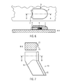
Figure 5 the release step of the exemplary head immobilization device is shown. - The
release element 17 is activated, such that the slopedsurface section 18 comes into contact with thebase portion 10 of theopen frame element 8. Theopen frame element 8 is pushed against the bias towards theleg fixture elements 3 and a lifting force is introduced by the slopedsurface section 18 to thebase portion 10. Thereby theopen frame element 8 is pushed upward and the head fixation element is released. The release element is described in more detail inFigure 8 . -
Figure 6 illustrates an embodiment of aleg fixture element 3. A profiled section A-A is shown. Theguidance element 4 provides four guiding surfaces in order to guide thereceptacle element 5. In this example theelastic element 6 is made from a foamy (elastical) rubber material. Thereceptacle elements 5 are made from plastic material and provide a concave surface to connect to the end portions 12 (not shown). -
Figure 7 shows an embodiment of thebase fixture element 13. The L-shapedprofile 14 is illustrated as well as the chamferededge 15 in the profiled section B-B. The complementary contouredrim portion 16 is carried out as a lateral kink inFigure 7 . -
Figure 8 shows an embodiment of therelease element 17 including a profiled section C-C. Therelease element 17 comprises a slopedsurface section 18 with the shape of atruncated cone 19. Thepivot axis 20 is parallel to the truncated cone axis 21 at a distance D. When a manual force is exerted on thehandle element 25 to rotate therelease element 17 about thepivot axis 20, thetruncated cone 19 is swiveled towards thebase portion 10 of the open frame element 8 (not shown). -
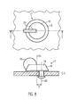
Figure 9 illustrates an embodiment of theguidance notch 23 and thepositioning element 24. Thebase fixture elements 13 comprise a V-shapedpositioning element 24. When theopen frame element 8 is moved towards thebase fixture elements 13 by the bias, the complementary shapedguidance notches 23 are positioned accurately onto the V-shapedpositioning elements 24. Thus theopen frame element 8 is positioned accurately relative to thebase fixture elements 13. - While the invention has been shown and described with reference to a certain preferred embodiment thereof, it will be understood by those skilled in the art that various changes in form and details may be made therein without departing from the spirit and scope of the invention as defined by the appended claims.
Claims (11)
- A head immobilization device for use in the medical field, comprising
a head fixation element (7), comprising a mask element (9) and an open frame element (8), said open frame element (8) comprising a base portion (10) and two legs (11) , each having an end portion (12), and
a support plate structure (1), comprising at least one base fixture element (13) for fixing the base portion (10) and at least two leg fixture elements (3) for fixing the legs (11), whereby said head fixation element (7) can be releasably connected with the support plate structure (1),
characterized in that
the at least two leg fixture elements (3) are designed to cooperate with the end portions (12) of the legs (11) such as to bias the head fixation element (7) in the direction of the at least one base fixture element (13). - A head immobilization device according to claim 1, wherein at least one leg fixture element (3) comprises an elastic element (6).
- A head immobilization device according to claim 1 and/or 2, wherein the support plate structure (1) comprises a release element (17) designed to exert a counterforce on the head fixation element (7) against the bias.
- A head immobilization device according to claim 3, wherein the release element (17) comprises a sloped surface section (18), which generates a lifting force on the head fixation element (7), when the release element (17) is activated.
- A head immobilization device according to claim 4, wherein the sloped surface section (18) comprises the shape of at least one sector of a truncated cone (19).
- A head immobilization device according to claim 5, wherein the release element (17) comprises a pivot axis (20), whereby the pivot axis (20) comprises an offset (D) to the axis (21) of the truncated cone.
- A head immobilization device according to any one of the previous claims, wherein the at least one base fixture element (13) comprises at least one profiled edge (14), in particularly wherein the at least one profiled edge (14) comprises an L-shaped and/or C-shaped profile.
- A head immobilization device according to any one of the previous claims, wherein the at least one base fixture element (13) comprises at least one chamfered edge portion (15).
- A head immobilization device according to any one of the previous claims, wherein the base portion (10) of the open frame element (8) comprises at least one contoured shoulder portion (22) and wherein the at least one base fixture element (13) comprises at least one complementary contoured rim portion (16).
- A head immobilization device according to any of the previous claims, wherein the open frame element (8) comprises at least one guidance notch (23) and wherein the support plate structure (1) and/or the base fixture element (13) comprises at least one positioning element (24), particularly wherein the at least one guidance notch (23) interacts with the at least one positioning element (24).
- A head fixation element (7) for use in a head immobilization device according to any of the previous claims,
characterized in that
the open frame element (8) comprises at least one guidance notch (23), which interacts with the at least one positioning element (24).
Priority Applications (1)
| Application Number | Priority Date | Filing Date | Title |
|---|---|---|---|
| EP11008466.2A EP2583634B1 (en) | 2011-10-21 | 2011-10-21 | Head immobilization device |
Applications Claiming Priority (1)
| Application Number | Priority Date | Filing Date | Title |
|---|---|---|---|
| EP11008466.2A EP2583634B1 (en) | 2011-10-21 | 2011-10-21 | Head immobilization device |
Publications (2)
| Publication Number | Publication Date |
|---|---|
| EP2583634A1 true EP2583634A1 (en) | 2013-04-24 |
| EP2583634B1 EP2583634B1 (en) | 2016-03-09 |
Family
ID=45390021
Family Applications (1)
| Application Number | Title | Priority Date | Filing Date |
|---|---|---|---|
| EP11008466.2A Not-in-force EP2583634B1 (en) | 2011-10-21 | 2011-10-21 | Head immobilization device |
Country Status (1)
| Country | Link |
|---|---|
| EP (1) | EP2583634B1 (en) |
Cited By (2)
| Publication number | Priority date | Publication date | Assignee | Title |
|---|---|---|---|---|
| WO2016050275A1 (en) * | 2014-09-30 | 2016-04-07 | Orfit Industries | Profile for the attachment of an immobilisation mask |
| DE102017126025A1 (en) * | 2017-11-07 | 2019-05-09 | Landratsamt Ortenaukreis | Radio-oncological head positioning device and radio-oncological patient positioning device |
Citations (4)
| Publication number | Priority date | Publication date | Assignee | Title |
|---|---|---|---|---|
| US5775337A (en) * | 1997-03-21 | 1998-07-07 | Biotek | Immobilization device |
| DE29813194U1 (en) * | 1998-07-24 | 1999-03-18 | Steurer Reiner | Head restraint system for optimal and quick fixation of the head |
| US20020038659A1 (en) * | 1999-10-29 | 2002-04-04 | Adil Al-Kassim | Immobilisation system |
| DE202011001492U1 (en) * | 2011-01-14 | 2011-05-26 | It-V Medizintechnik Gmbh | Mask and storage device for radiological diagnosis and / or radio-oncological treatment |
-
2011
- 2011-10-21 EP EP11008466.2A patent/EP2583634B1/en not_active Not-in-force
Patent Citations (4)
| Publication number | Priority date | Publication date | Assignee | Title |
|---|---|---|---|---|
| US5775337A (en) * | 1997-03-21 | 1998-07-07 | Biotek | Immobilization device |
| DE29813194U1 (en) * | 1998-07-24 | 1999-03-18 | Steurer Reiner | Head restraint system for optimal and quick fixation of the head |
| US20020038659A1 (en) * | 1999-10-29 | 2002-04-04 | Adil Al-Kassim | Immobilisation system |
| DE202011001492U1 (en) * | 2011-01-14 | 2011-05-26 | It-V Medizintechnik Gmbh | Mask and storage device for radiological diagnosis and / or radio-oncological treatment |
Cited By (6)
| Publication number | Priority date | Publication date | Assignee | Title |
|---|---|---|---|---|
| WO2016050275A1 (en) * | 2014-09-30 | 2016-04-07 | Orfit Industries | Profile for the attachment of an immobilisation mask |
| US20170252201A1 (en) * | 2014-09-30 | 2017-09-07 | Orfit Industries | Profile for the attachment of an immobilisation mask |
| CN107155298A (en) * | 2014-09-30 | 2017-09-12 | 奥菲特工业公司 | Profile shapes for the mask that is connected |
| US10786385B2 (en) * | 2014-09-30 | 2020-09-29 | Orfit Industries | Profile for the attachment of an immobilisation mask |
| CN107155298B (en) * | 2014-09-30 | 2021-02-02 | 奥菲特工业公司 | Profile for connecting fixing mask |
| DE102017126025A1 (en) * | 2017-11-07 | 2019-05-09 | Landratsamt Ortenaukreis | Radio-oncological head positioning device and radio-oncological patient positioning device |
Also Published As
| Publication number | Publication date |
|---|---|
| EP2583634B1 (en) | 2016-03-09 |
Similar Documents
| Publication | Publication Date | Title |
|---|---|---|
| US11937985B2 (en) | Cranial immobilization system | |
| JP6571174B2 (en) | Bone fixation assembly | |
| US7063461B2 (en) | Patient support device with shoulder depression device | |
| JP6751136B2 (en) | Support robot for neurosurgery | |
| CN111419429A (en) | Adjustable fixator apparatus and method for fixing a patient | |
| US10940032B2 (en) | Device for treating carpal tunnel syndrome of a person's hand | |
| US20120184956A1 (en) | Apparatus and method for stabilizing a needle | |
| EP2583634B1 (en) | Head immobilization device | |
| EP2911605B1 (en) | Patient positioning device for stereotactic radiosurgery | |
| JP5415423B2 (en) | Adjustable surgical instruments | |
| US11701135B2 (en) | Medical instrument with cleaning gap in the closure region | |
| JP2016533223A (en) | Patient support unit for devices for supporting patients who are x-ray examined during surgery | |
| EP1333766A1 (en) | Halo crown | |
| US20160317139A1 (en) | Retraction system | |
| KR101927489B1 (en) | Supporting structure for handpiece of skin treatment apparatus and skin treatment apparatus having the same | |
| KR101442741B1 (en) | Fixing device for beam spoiler | |
| US20200214791A1 (en) | Medical device retention system | |
| CN116098651B (en) | Fixing device for instrument and instrument table using the same | |
| CN204121360U (en) | Operation bracket device | |
| EP1095640A1 (en) | Immobilisation system | |
| US20140257041A1 (en) | Perineal retractor | |
| CN104586597B (en) | operation bracket device | |
| KR102201822B1 (en) | Inserting apparatus for medical treatment implant | |
| KR101642059B1 (en) | Cannula fixing apparatus | |
| KR20130028794A (en) | Chiropractic device having alignment-by-touch function |
Legal Events
| Date | Code | Title | Description |
|---|---|---|---|
| PUAI | Public reference made under article 153(3) epc to a published international application that has entered the european phase |
Free format text: ORIGINAL CODE: 0009012 |
|
| AK | Designated contracting states |
Kind code of ref document: A1 Designated state(s): AL AT BE BG CH CY CZ DE DK EE ES FI FR GB GR HR HU IE IS IT LI LT LU LV MC MK MT NL NO PL PT RO RS SE SI SK SM TR |
|
| AX | Request for extension of the european patent |
Extension state: BA ME |
|
| 17P | Request for examination filed |
Effective date: 20131024 |
|
| RBV | Designated contracting states (corrected) |
Designated state(s): AL AT BE BG CH CY CZ DE DK EE ES FI FR GB GR HR HU IE IS IT LI LT LU LV MC MK MT NL NO PL PT RO RS SE SI SK SM TR |
|
| 17Q | First examination report despatched |
Effective date: 20140218 |
|
| GRAP | Despatch of communication of intention to grant a patent |
Free format text: ORIGINAL CODE: EPIDOSNIGR1 |
|
| RIC1 | Information provided on ipc code assigned before grant |
Ipc: A61B 19/00 20060101AFI20150728BHEP Ipc: A61B 6/04 20060101ALN20150728BHEP |
|
| INTG | Intention to grant announced |
Effective date: 20150813 |
|
| GRAS | Grant fee paid |
Free format text: ORIGINAL CODE: EPIDOSNIGR3 |
|
| REG | Reference to a national code |
Ref country code: DE Ref legal event code: R079 Ref document number: 602011023777 Country of ref document: DE Free format text: PREVIOUS MAIN CLASS: A61B0019000000 Ipc: A61B0090000000 |
|
| GRAA | (expected) grant |
Free format text: ORIGINAL CODE: 0009210 |
|
| RIC1 | Information provided on ipc code assigned before grant |
Ipc: A61B 90/18 20160101ALI20160113BHEP Ipc: A61B 6/04 20060101ALI20160113BHEP Ipc: A61B 90/00 20160101AFI20160113BHEP |
|
| AK | Designated contracting states |
Kind code of ref document: B1 Designated state(s): AL AT BE BG CH CY CZ DE DK EE ES FI FR GB GR HR HU IE IS IT LI LT LU LV MC MK MT NL NO PL PT RO RS SE SI SK SM TR |
|
| REG | Reference to a national code |
Ref country code: GB Ref legal event code: FG4D |
|
| REG | Reference to a national code |
Ref country code: AT Ref legal event code: REF Ref document number: 778907 Country of ref document: AT Kind code of ref document: T Effective date: 20160315 Ref country code: CH Ref legal event code: EP Ref country code: CH Ref legal event code: NV Representative=s name: BOVARD AG, CH |
|
| REG | Reference to a national code |
Ref country code: IE Ref legal event code: FG4D |
|
| REG | Reference to a national code |
Ref country code: DE Ref legal event code: R096 Ref document number: 602011023777 Country of ref document: DE |
|
| REG | Reference to a national code |
Ref country code: LT Ref legal event code: MG4D |
|
| REG | Reference to a national code |
Ref country code: NL Ref legal event code: MP Effective date: 20160309 |
|
| PG25 | Lapsed in a contracting state [announced via postgrant information from national office to epo] |
Ref country code: GR Free format text: LAPSE BECAUSE OF FAILURE TO SUBMIT A TRANSLATION OF THE DESCRIPTION OR TO PAY THE FEE WITHIN THE PRESCRIBED TIME-LIMIT Effective date: 20160610 Ref country code: NO Free format text: LAPSE BECAUSE OF FAILURE TO SUBMIT A TRANSLATION OF THE DESCRIPTION OR TO PAY THE FEE WITHIN THE PRESCRIBED TIME-LIMIT Effective date: 20160609 Ref country code: FI Free format text: LAPSE BECAUSE OF FAILURE TO SUBMIT A TRANSLATION OF THE DESCRIPTION OR TO PAY THE FEE WITHIN THE PRESCRIBED TIME-LIMIT Effective date: 20160309 Ref country code: HR Free format text: LAPSE BECAUSE OF FAILURE TO SUBMIT A TRANSLATION OF THE DESCRIPTION OR TO PAY THE FEE WITHIN THE PRESCRIBED TIME-LIMIT Effective date: 20160309 Ref country code: ES Free format text: LAPSE BECAUSE OF FAILURE TO SUBMIT A TRANSLATION OF THE DESCRIPTION OR TO PAY THE FEE WITHIN THE PRESCRIBED TIME-LIMIT Effective date: 20160309 |
|
| REG | Reference to a national code |
Ref country code: AT Ref legal event code: MK05 Ref document number: 778907 Country of ref document: AT Kind code of ref document: T Effective date: 20160309 |
|
| PG25 | Lapsed in a contracting state [announced via postgrant information from national office to epo] |
Ref country code: LV Free format text: LAPSE BECAUSE OF FAILURE TO SUBMIT A TRANSLATION OF THE DESCRIPTION OR TO PAY THE FEE WITHIN THE PRESCRIBED TIME-LIMIT Effective date: 20160309 Ref country code: NL Free format text: LAPSE BECAUSE OF FAILURE TO SUBMIT A TRANSLATION OF THE DESCRIPTION OR TO PAY THE FEE WITHIN THE PRESCRIBED TIME-LIMIT Effective date: 20160309 Ref country code: LT Free format text: LAPSE BECAUSE OF FAILURE TO SUBMIT A TRANSLATION OF THE DESCRIPTION OR TO PAY THE FEE WITHIN THE PRESCRIBED TIME-LIMIT Effective date: 20160309 Ref country code: PL Free format text: LAPSE BECAUSE OF FAILURE TO SUBMIT A TRANSLATION OF THE DESCRIPTION OR TO PAY THE FEE WITHIN THE PRESCRIBED TIME-LIMIT Effective date: 20160309 Ref country code: SE Free format text: LAPSE BECAUSE OF FAILURE TO SUBMIT A TRANSLATION OF THE DESCRIPTION OR TO PAY THE FEE WITHIN THE PRESCRIBED TIME-LIMIT Effective date: 20160309 Ref country code: RS Free format text: LAPSE BECAUSE OF FAILURE TO SUBMIT A TRANSLATION OF THE DESCRIPTION OR TO PAY THE FEE WITHIN THE PRESCRIBED TIME-LIMIT Effective date: 20160309 |
|
| PG25 | Lapsed in a contracting state [announced via postgrant information from national office to epo] |
Ref country code: EE Free format text: LAPSE BECAUSE OF FAILURE TO SUBMIT A TRANSLATION OF THE DESCRIPTION OR TO PAY THE FEE WITHIN THE PRESCRIBED TIME-LIMIT Effective date: 20160309 Ref country code: IS Free format text: LAPSE BECAUSE OF FAILURE TO SUBMIT A TRANSLATION OF THE DESCRIPTION OR TO PAY THE FEE WITHIN THE PRESCRIBED TIME-LIMIT Effective date: 20160709 |
|
| PG25 | Lapsed in a contracting state [announced via postgrant information from national office to epo] |
Ref country code: AT Free format text: LAPSE BECAUSE OF FAILURE TO SUBMIT A TRANSLATION OF THE DESCRIPTION OR TO PAY THE FEE WITHIN THE PRESCRIBED TIME-LIMIT Effective date: 20160309 Ref country code: PT Free format text: LAPSE BECAUSE OF FAILURE TO SUBMIT A TRANSLATION OF THE DESCRIPTION OR TO PAY THE FEE WITHIN THE PRESCRIBED TIME-LIMIT Effective date: 20160711 Ref country code: SM Free format text: LAPSE BECAUSE OF FAILURE TO SUBMIT A TRANSLATION OF THE DESCRIPTION OR TO PAY THE FEE WITHIN THE PRESCRIBED TIME-LIMIT Effective date: 20160309 Ref country code: SK Free format text: LAPSE BECAUSE OF FAILURE TO SUBMIT A TRANSLATION OF THE DESCRIPTION OR TO PAY THE FEE WITHIN THE PRESCRIBED TIME-LIMIT Effective date: 20160309 Ref country code: RO Free format text: LAPSE BECAUSE OF FAILURE TO SUBMIT A TRANSLATION OF THE DESCRIPTION OR TO PAY THE FEE WITHIN THE PRESCRIBED TIME-LIMIT Effective date: 20160309 |
|
| REG | Reference to a national code |
Ref country code: DE Ref legal event code: R097 Ref document number: 602011023777 Country of ref document: DE |
|
| PG25 | Lapsed in a contracting state [announced via postgrant information from national office to epo] |
Ref country code: BE Free format text: LAPSE BECAUSE OF FAILURE TO SUBMIT A TRANSLATION OF THE DESCRIPTION OR TO PAY THE FEE WITHIN THE PRESCRIBED TIME-LIMIT Effective date: 20160309 Ref country code: IT Free format text: LAPSE BECAUSE OF FAILURE TO SUBMIT A TRANSLATION OF THE DESCRIPTION OR TO PAY THE FEE WITHIN THE PRESCRIBED TIME-LIMIT Effective date: 20160309 |
|
| PLBE | No opposition filed within time limit |
Free format text: ORIGINAL CODE: 0009261 |
|
| STAA | Information on the status of an ep patent application or granted ep patent |
Free format text: STATUS: NO OPPOSITION FILED WITHIN TIME LIMIT |
|
| PG25 | Lapsed in a contracting state [announced via postgrant information from national office to epo] |
Ref country code: DK Free format text: LAPSE BECAUSE OF FAILURE TO SUBMIT A TRANSLATION OF THE DESCRIPTION OR TO PAY THE FEE WITHIN THE PRESCRIBED TIME-LIMIT Effective date: 20160309 |
|
| PGFP | Annual fee paid to national office [announced via postgrant information from national office to epo] |
Ref country code: CH Payment date: 20161022 Year of fee payment: 6 Ref country code: CZ Payment date: 20161005 Year of fee payment: 6 Ref country code: DE Payment date: 20161027 Year of fee payment: 6 |
|
| 26N | No opposition filed |
Effective date: 20161212 |
|
| PG25 | Lapsed in a contracting state [announced via postgrant information from national office to epo] |
Ref country code: BG Free format text: LAPSE BECAUSE OF FAILURE TO SUBMIT A TRANSLATION OF THE DESCRIPTION OR TO PAY THE FEE WITHIN THE PRESCRIBED TIME-LIMIT Effective date: 20160609 |
|
| PG25 | Lapsed in a contracting state [announced via postgrant information from national office to epo] |
Ref country code: SI Free format text: LAPSE BECAUSE OF FAILURE TO SUBMIT A TRANSLATION OF THE DESCRIPTION OR TO PAY THE FEE WITHIN THE PRESCRIBED TIME-LIMIT Effective date: 20160309 |
|
| GBPC | Gb: european patent ceased through non-payment of renewal fee |
Effective date: 20161021 |
|
| REG | Reference to a national code |
Ref country code: IE Ref legal event code: MM4A |
|
| REG | Reference to a national code |
Ref country code: FR Ref legal event code: ST Effective date: 20170630 |
|
| PG25 | Lapsed in a contracting state [announced via postgrant information from national office to epo] |
Ref country code: GB Free format text: LAPSE BECAUSE OF NON-PAYMENT OF DUE FEES Effective date: 20161021 Ref country code: FR Free format text: LAPSE BECAUSE OF NON-PAYMENT OF DUE FEES Effective date: 20161102 |
|
| PG25 | Lapsed in a contracting state [announced via postgrant information from national office to epo] |
Ref country code: LU Free format text: LAPSE BECAUSE OF NON-PAYMENT OF DUE FEES Effective date: 20161021 |
|
| PG25 | Lapsed in a contracting state [announced via postgrant information from national office to epo] |
Ref country code: IE Free format text: LAPSE BECAUSE OF NON-PAYMENT OF DUE FEES Effective date: 20161021 |
|
| REG | Reference to a national code |
Ref country code: DE Ref legal event code: R119 Ref document number: 602011023777 Country of ref document: DE |
|
| PG25 | Lapsed in a contracting state [announced via postgrant information from national office to epo] |
Ref country code: CY Free format text: LAPSE BECAUSE OF FAILURE TO SUBMIT A TRANSLATION OF THE DESCRIPTION OR TO PAY THE FEE WITHIN THE PRESCRIBED TIME-LIMIT Effective date: 20160309 Ref country code: HU Free format text: LAPSE BECAUSE OF FAILURE TO SUBMIT A TRANSLATION OF THE DESCRIPTION OR TO PAY THE FEE WITHIN THE PRESCRIBED TIME-LIMIT; INVALID AB INITIO Effective date: 20111021 |
|
| REG | Reference to a national code |
Ref country code: CH Ref legal event code: PL |
|
| PG25 | Lapsed in a contracting state [announced via postgrant information from national office to epo] |
Ref country code: TR Free format text: LAPSE BECAUSE OF FAILURE TO SUBMIT A TRANSLATION OF THE DESCRIPTION OR TO PAY THE FEE WITHIN THE PRESCRIBED TIME-LIMIT Effective date: 20160309 Ref country code: MK Free format text: LAPSE BECAUSE OF FAILURE TO SUBMIT A TRANSLATION OF THE DESCRIPTION OR TO PAY THE FEE WITHIN THE PRESCRIBED TIME-LIMIT Effective date: 20160309 Ref country code: MT Free format text: LAPSE BECAUSE OF NON-PAYMENT OF DUE FEES Effective date: 20161031 Ref country code: MC Free format text: LAPSE BECAUSE OF FAILURE TO SUBMIT A TRANSLATION OF THE DESCRIPTION OR TO PAY THE FEE WITHIN THE PRESCRIBED TIME-LIMIT Effective date: 20160309 |
|
| PG25 | Lapsed in a contracting state [announced via postgrant information from national office to epo] |
Ref country code: CZ Free format text: LAPSE BECAUSE OF NON-PAYMENT OF DUE FEES Effective date: 20171021 Ref country code: DE Free format text: LAPSE BECAUSE OF NON-PAYMENT OF DUE FEES Effective date: 20180501 Ref country code: CH Free format text: LAPSE BECAUSE OF NON-PAYMENT OF DUE FEES Effective date: 20171031 Ref country code: LI Free format text: LAPSE BECAUSE OF NON-PAYMENT OF DUE FEES Effective date: 20171031 |
|
| PG25 | Lapsed in a contracting state [announced via postgrant information from national office to epo] |
Ref country code: AL Free format text: LAPSE BECAUSE OF FAILURE TO SUBMIT A TRANSLATION OF THE DESCRIPTION OR TO PAY THE FEE WITHIN THE PRESCRIBED TIME-LIMIT Effective date: 20160309 |