EP2582415B1 - Flow filter for separating blood into plasma and cellular constituents - Google Patents
Flow filter for separating blood into plasma and cellular constituents Download PDFInfo
- Publication number
- EP2582415B1 EP2582415B1 EP11738982.5A EP11738982A EP2582415B1 EP 2582415 B1 EP2582415 B1 EP 2582415B1 EP 11738982 A EP11738982 A EP 11738982A EP 2582415 B1 EP2582415 B1 EP 2582415B1
- Authority
- EP
- European Patent Office
- Prior art keywords
- bundle
- filter
- flow
- blood
- plasma
- Prior art date
- Legal status (The legal status is an assumption and is not a legal conclusion. Google has not performed a legal analysis and makes no representation as to the accuracy of the status listed.)
- Active
Links
- 210000004369 blood Anatomy 0.000 title claims description 41
- 239000008280 blood Substances 0.000 title claims description 41
- 230000001413 cellular effect Effects 0.000 title claims description 10
- 239000000470 constituent Substances 0.000 title claims 2
- 210000004027 cell Anatomy 0.000 claims description 19
- 239000011148 porous material Substances 0.000 claims description 18
- 239000012528 membrane Substances 0.000 claims description 14
- 210000000265 leukocyte Anatomy 0.000 claims description 12
- 239000000835 fiber Substances 0.000 claims description 10
- 239000012510 hollow fiber Substances 0.000 description 30
- 230000036770 blood supply Effects 0.000 description 6
- 238000000926 separation method Methods 0.000 description 6
- 230000002706 hydrostatic effect Effects 0.000 description 5
- 230000003068 static effect Effects 0.000 description 4
- 210000003743 erythrocyte Anatomy 0.000 description 3
- 230000005484 gravity Effects 0.000 description 3
- RSGFPIWWSCWCFJ-VAXZQHAWSA-N 2-hydroxypropane-1,2,3-tricarboxylic acid;(2r,3s,4r,5r)-2,3,4,5,6-pentahydroxyhexanal;phosphoric acid Chemical compound OP(O)(O)=O.OC[C@@H](O)[C@@H](O)[C@H](O)[C@@H](O)C=O.OC(=O)CC(O)(C(O)=O)CC(O)=O RSGFPIWWSCWCFJ-VAXZQHAWSA-N 0.000 description 2
- 230000007423 decrease Effects 0.000 description 2
- 238000007599 discharging Methods 0.000 description 2
- 230000000694 effects Effects 0.000 description 2
- 230000001105 regulatory effect Effects 0.000 description 2
- 206010053567 Coagulopathies Diseases 0.000 description 1
- 101100390736 Danio rerio fign gene Proteins 0.000 description 1
- 101100390738 Mus musculus Fign gene Proteins 0.000 description 1
- 230000001133 acceleration Effects 0.000 description 1
- 230000017531 blood circulation Effects 0.000 description 1
- 210000001772 blood platelet Anatomy 0.000 description 1
- 230000035602 clotting Effects 0.000 description 1
- 238000010276 construction Methods 0.000 description 1
- 230000003247 decreasing effect Effects 0.000 description 1
- 238000005534 hematocrit Methods 0.000 description 1
- 210000004698 lymphocyte Anatomy 0.000 description 1
- 239000012982 microporous membrane Substances 0.000 description 1
- 210000001616 monocyte Anatomy 0.000 description 1
- 210000002966 serum Anatomy 0.000 description 1
- 239000003381 stabilizer Substances 0.000 description 1
- 230000007704 transition Effects 0.000 description 1
Images


Classifications
-
- A—HUMAN NECESSITIES
- A61—MEDICAL OR VETERINARY SCIENCE; HYGIENE
- A61M—DEVICES FOR INTRODUCING MEDIA INTO, OR ONTO, THE BODY; DEVICES FOR TRANSDUCING BODY MEDIA OR FOR TAKING MEDIA FROM THE BODY; DEVICES FOR PRODUCING OR ENDING SLEEP OR STUPOR
- A61M1/00—Suction or pumping devices for medical purposes; Devices for carrying-off, for treatment of, or for carrying-over, body-liquids; Drainage systems
- A61M1/34—Filtering material out of the blood by passing it through a membrane, i.e. hemofiltration or diafiltration
- A61M1/3496—Plasmapheresis; Leucopheresis; Lymphopheresis
-
- A—HUMAN NECESSITIES
- A61—MEDICAL OR VETERINARY SCIENCE; HYGIENE
- A61M—DEVICES FOR INTRODUCING MEDIA INTO, OR ONTO, THE BODY; DEVICES FOR TRANSDUCING BODY MEDIA OR FOR TAKING MEDIA FROM THE BODY; DEVICES FOR PRODUCING OR ENDING SLEEP OR STUPOR
- A61M1/00—Suction or pumping devices for medical purposes; Devices for carrying-off, for treatment of, or for carrying-over, body-liquids; Drainage systems
- A61M1/02—Blood transfusion apparatus
- A61M1/0209—Multiple bag systems for separating or storing blood components
- A61M1/0218—Multiple bag systems for separating or storing blood components with filters
-
- B—PERFORMING OPERATIONS; TRANSPORTING
- B01—PHYSICAL OR CHEMICAL PROCESSES OR APPARATUS IN GENERAL
- B01D—SEPARATION
- B01D61/00—Processes of separation using semi-permeable membranes, e.g. dialysis, osmosis or ultrafiltration; Apparatus, accessories or auxiliary operations specially adapted therefor
- B01D61/02—Reverse osmosis; Hyperfiltration ; Nanofiltration
-
- B—PERFORMING OPERATIONS; TRANSPORTING
- B01—PHYSICAL OR CHEMICAL PROCESSES OR APPARATUS IN GENERAL
- B01D—SEPARATION
- B01D63/00—Apparatus in general for separation processes using semi-permeable membranes
- B01D63/02—Hollow fibre modules
- B01D63/04—Hollow fibre modules comprising multiple hollow fibre assemblies
-
- A—HUMAN NECESSITIES
- A61—MEDICAL OR VETERINARY SCIENCE; HYGIENE
- A61M—DEVICES FOR INTRODUCING MEDIA INTO, OR ONTO, THE BODY; DEVICES FOR TRANSDUCING BODY MEDIA OR FOR TAKING MEDIA FROM THE BODY; DEVICES FOR PRODUCING OR ENDING SLEEP OR STUPOR
- A61M1/00—Suction or pumping devices for medical purposes; Devices for carrying-off, for treatment of, or for carrying-over, body-liquids; Drainage systems
- A61M1/02—Blood transfusion apparatus
- A61M1/0209—Multiple bag systems for separating or storing blood components
- A61M1/0218—Multiple bag systems for separating or storing blood components with filters
- A61M1/0222—Multiple bag systems for separating or storing blood components with filters and filter bypass
-
- B—PERFORMING OPERATIONS; TRANSPORTING
- B01—PHYSICAL OR CHEMICAL PROCESSES OR APPARATUS IN GENERAL
- B01D—SEPARATION
- B01D2311/00—Details relating to membrane separation process operations and control
- B01D2311/14—Pressure control
-
- B—PERFORMING OPERATIONS; TRANSPORTING
- B01—PHYSICAL OR CHEMICAL PROCESSES OR APPARATUS IN GENERAL
- B01D—SEPARATION
- B01D2313/00—Details relating to membrane modules or apparatus
- B01D2313/18—Specific valves
Definitions
- the present invention relates to a flow-through filter for separating blood into plasma and cellular components (erythrocytes, platelets, leukocytes) or into a plasma fraction and a fraction of cellular components.
- Filter devices for separating blood into certain fractions are, for example, from the references EP 1 309 363 B1 . DE 102 39 658 A1 , the EP 1 089 778 B1 . DE 295 16 471 U1 . EP 0 893 130 B1 . EP 0 868 208 B1 . DE 200 14 311 U1 and EP-A-0096973 known.
- the blood taken from a donor is passed through a arranged in a filter housing U-shaped bundle of fibers whose walls are formed from a fine-pored membrane, the pores of the membrane for the cellular components of the blood are too small, so this through the fibers are passed into a corresponding vessel (eg a bag).
- the plasma passes through the pores into the filter housing and is discharged from there into another vessel (eg a bag).
- this filter device has the disadvantage that the change in the static pressure acting perpendicular to the wall, which ultimately determines the amount of plasma that passes through the pores, and thus the separation efficiency, is not taken into account. This change results from the increase in density or increase in hematocrit as a function of the flow path traveled in the fibers.
- a flow filter for separating blood into plasma and cellular components (1) comprises a filter housing comprising a blood supply, a plasma discharge and a cell discharge, (2) a fine-pored membrane comprising (a) a bundle of parallel connected hollow fibers disposed in the filter housing and having an inflow end connected to the blood supply line, and (b) the filter housing in a first flow space connected to the cell drain and a second flow space connected to the plasma And (3) a pressure adjusting device for adjusting the pressure in the hollow fibers, which is connected to an outflow end of the bundle.
- the pressure ratios in the bundle can be regulated by opposing a corresponding flow resistance to the blood flowing into the bundle or filter housing.
- the curve of the pressure curve along each hollow fiber of the static pressure decisive for the separation of the plasma is a strictly monotonically increasing function, which is shifted upwards by the application of pressure.
- the flow velocity curve is a strictly monotonically decreasing function that corresponds to the dynamic pressure.
- the Druckeinstellvoroplasty comprises a hose which can be acted upon by an external pressure.
- “Externally” means that a suitable pressurizing means, which is applied to the bundle, is arranged outside the passage filter and exerts its effect via the hose line.
- the pressure adjusting device in this case comprises a control valve (throttle valve), which in the cell discharge arranged and adapted to change the flow cross-section.
- the dynamic pressure can simply be adjusted by guiding the cell discharge upwards and thus utilizing the hydrostatic pressure of the plasma-poor blood flowing therein.
- the pressure adjusting device comprises a second microporous membrane comprising a second bundle of second hollow fibers disposed in the filter housing and having a first end connected to the second end of the bundle and a second end connected to the cell lead.
- the second fine-pored membrane or the second bundle is used according to this embodiment as Druckeinstellvoriques; They thus have a double function: second filter step + backpressure generation.
- the orientation of the second bundle is basically independent of that of the bundle.
- to generate a suitable back pressure its flow resistance, the hydrostatic pressure formed by its vertical arrangement and / or a control valve, as described above, can be combined.
- the hollow fibers of the bundle have a different size than the second bundle, ideally those of the bundle are smaller than those of the second bundle.
- the smaller size has the advantage that not too much plasma in the first flow section (the bundle) is removed from the blood, so that this does not lose its good flow characteristics.
- the pores are larger in order to better remove the remaining plasma from the blood.
- the number of hollow fibers and the number of second hollow fibers are different.
- the advantages of this embodiment are described in detail below in connection with a specific embodiment.
- the bundle and the second bundle are each secured with their first end and their second end in the filter housing so that their hollow fibers do not touch, and are the hollow fiber bundle and the second hollow fiber bundle through a connecting tube connected outside the filter housing.
- the filter according to the invention has the advantage that the plasma emerging from the hollow fibers does not lead to a sticking (adhesion) of the hollow fibers, which is described in US Pat EP 1 309 363 B1 can easily happen.
- the hollow fibers "stick" to each other, so that the pores are in the end clogged.
- the distance between the hollow fibers is achieved by fixing their first and second ends in opposite wall sections, for example a top cover and a bottom cover, under a well-defined bias in the filter housing.
- the filter housing comprises a first chamber in which the bundle is arranged, and a second chamber dense relative to the first chamber, in which the second bundle is arranged, wherein the plasma discharge with the first chamber and a second cell lead is connected to the second chamber.
- the hollow fiber bundle and the second hollow fiber bundle each extend vertically in the filter housing. This has the advantage that the transport operations can be effected solely by gravity.
- a check valve is arranged in the connecting tube.
- the check valve advantageously serves to prevent backflow, if for procedural reasons higher pressure in the second bundle is to be generated, which should not be transferred to the bundle.
- the size of the pores of the first fine-pored membrane and the size of the pores of the second fine-pored membrane are different.
- the pore size is one way of adjusting the amount of plasma and the nature of the separated parts.
- the blood line is connected to a blood bag arranged at a predetermined distance above the filter housing.
- the input pressure ie the pressure at the entrance of the blood into the flow filter - if no other flow obstacles such as a leukocyte filter or a drip chamber in the connection between the flow filter and blood bag are connected - depends solely on the difference in height, d. H. how far the blood bag is placed over the flow filter. This position can be advantageously determined depending on the characteristics of the bundles used.
- a filter assembly comprises (a) a blood bag, (b) a leukocyte filter, (c) a flow-through filter according to any one of claims 1 to 9 and a cell bag, and (d) a plasma bag wherein elements (a) - (d) arranged in this order at increasingly lower levels.
- the filter arrangement comprises a bypass line for bypassing the leukocyte filter.
- FIG. 12 shows an exemplary filter arrangement in which the flow-through filter according to the present invention may be used, with "top” and “bottom” in FIG Fig. 1 find their equivalent realiter in the vertical arrangement of the components, so that the whole blood (hereinafter referred to as "blood”) solely by gravity - according to the arrows drawn - can be moved through the filter assembly.
- the filter assembly essentially comprises a blood bag 10 which is connected to a cannula 12 via which blood is drawn from a donor (not shown). Below the blood bag 10 and connected thereto via a hose is a leukocyte filter 14, which, however, can be bypassed via a bypass line 16.
- the passage filter 100 which is arranged via hoses on the one hand with a erytrocyte bag 18, which is arranged next to the passage filter 100, and on the other hand with a plasma bag 20, which is arranged below the passage filter 100 , connected is.
- the height difference between the blood bag 10 and the passage filter 100 is about 100 cm, that between the passage filter 100 and the plasma bag about 50 cm.
- the dispenser is connected to the filter arrangement via the cannula 12.
- the blood runs with the help of the cannula 12 directly into the blood bag 10, in which a CPD (citrate-phosphate-dextrose) stabilizer solution u. a. to prevent the blood from clotting.
- CPD cetyl-phosphate-dextrose
- Fig. 1 Also contains a drip chamber T, various valves, etc., which have only perifere meaning for the present invention and therefore are not described in detail here.
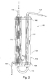
- Fig. 2 shows an advantageous embodiment of the passage filter according to the invention 100.
- the passage filter 100 comprises a tubular filter housing 102 having a wall 104 in the form of a right circular cylinder, an upper cover 106 and a lower cover 108.
- a first bundle 110 of hollow fibers and a second bundle 112 of hollow fibers are arranged parallel to each other in a vertikelen alignment.
- the wall of each hollow fiber is formed of a fine-pored membrane.
- the number of hollow fibers which are identical in both bundles 110, 112 according to the embodiment is greater in the first bundle 110 than in the second bundle 112.
- the bundles 110, 112 are connected to each other below the filter housing 104 via a connecting tube 114. Further, the upper end of the first bundle 110 is connected to a blood supply line 116 for supplying the - possibly leukocytes substantially freed - blood and the upper end of the second bundle 112 with a cell lead 118 for discharging the cellular components of the blood. In addition, a lower end portion of the filter housing 102 is connected to a plasma discharge line 120 for discharging the plasma.
- the membranes of the hollow fibers separate the interior of the filter housing 104 into a first flow space, which is connected to the cell outlet 118, and a second flow space, which is connected to the plasma discharge 120.
- the total length of the hollow fibers of both bundles 110, 112 is about 600 m, the inner diameter of each fiber about 300 microns, the wall thickness of about 20 microns and their pore diameter about 0.7 microns.
- the diameter of an erythrocyte is approximately 7.5 ⁇ m, and that of the leukocytes is between approximately 7.5 ⁇ m in lymphocytes and 20 ⁇ m in monocytes.
- the flow rate decreases due to leakage of plasma from the hollow fiber continuously, while the density of the blood increases, as mentioned above.
- the flow rate at the end of the first bundle 110 is less than the Flow rate at the beginning of the second bundle 112. It rises abruptly at the transition, and then continuously decrease along each fiber of the second bundle 112 again. As a result, the amount of plasma filtered per unit time is greatest at the lower end of the first bundle 110 and the upper end of the second bundle 112, since the static pressure is highest here. In this arrangement, the second bundle 112 creates a back pressure in the first bundle 110 due to the restricted flow cross section and the acceleration work.
- the amount of back pressure acts to brake back on the blood flow in the first bundle 110, thereby regulating the per unit time of the hollow fibers of the first bundle 110 exiting plasma is achieved.
- the amount of this back pressure can be determined constructively by changing the flow cross-section of the second bundle 112 relative to the first bundle 110. It should be noted that a force opposite to the flow direction is also exerted on the blood by the hydrostatic pressure in the second bundle 112, provided that the inner diameter of the hollow fibers is chosen to be so large that the gravitational effect is greater than the cohesive one.
- the second bundle 112 thus acts as the pressure adjusting device according to the invention.
- bundles 110, 112 opposite to those in FIG Fig. 1 may be advantageous to use bundles 110, 112 opposite to those in FIG Fig. 1 to swap shown arrangement, so that in the second bundle 112 with the then higher number of hollow fibers, a lower flow velocity and thus a higher static pressure is present.
- the plasma which is present at the end of the leading through the filter housing 102 flow path in only a small amount can be removed more efficiently.
- Fig. 3 shows another embodiment of a flow filter 100.
- the flow filter 100 according to this embodiment is different from that in FIG Fig. 2 shown in that instead of the second bundle 112 a riser or riser 122 is used and additionally a metering valve 124 is disposed in the cell drain 118.
- the riser 122 and the metering valve 124 act according to this embodiment together as the pressure adjusting device according to the invention, via the hydrostatic pressure or the adjustment of the flow cross-section.
- an adjustable flow resistance which in turn determines the pressure conditions in the bundles 110, 112, can be opposed to the hydrostatic pressure generated by the blood bag 10 arranged above the passage filter 100 according to the invention.
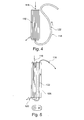
- Fig. 4 shows a further embodiment, which differs from the in Fig. 3 is distinguished by two features: (a) the riser 122 is guided upwardly outside of the filter housing 102, and (b) the space thereby vacated in the housing 102 is completely occupied by the first bundle 110.
- the blood supply line can also be guided either outside or inside the filter housing 102 down and the blood can be coupled from below into the fiber, whereby a flow reversal is achieved.
- Fig. 5 shows a further embodiment, which differs from the in Fig. 4 shown differs in that attached to the housing 102, a guide 126 for the riser 122 - advantageously integrally connected thereto - is, so that the riser 122 is not exposed, but is received protected.
Landscapes
- Health & Medical Sciences (AREA)
- Heart & Thoracic Surgery (AREA)
- Engineering & Computer Science (AREA)
- Chemical & Material Sciences (AREA)
- Anesthesiology (AREA)
- Biomedical Technology (AREA)
- Hematology (AREA)
- Life Sciences & Earth Sciences (AREA)
- Animal Behavior & Ethology (AREA)
- General Health & Medical Sciences (AREA)
- Public Health (AREA)
- Veterinary Medicine (AREA)
- Vascular Medicine (AREA)
- Water Supply & Treatment (AREA)
- Chemical Kinetics & Catalysis (AREA)
- Nanotechnology (AREA)
- External Artificial Organs (AREA)
Description
Die vorliegende Erfindung betrifft einen Durchflussfilter zum Separieren von Blut in Plasma und zelluläre Bestandteile (Erythrozyten, Thrombozyten, Leukozyten) bzw. in eine Plasmafraktion und eine Fraktion zellulärer Bestandteile.The present invention relates to a flow-through filter for separating blood into plasma and cellular components (erythrocytes, platelets, leukocytes) or into a plasma fraction and a fraction of cellular components.
Filtervorrichtungen zum Separieren von Blut in bestimmte Fraktionen sind zum Beispiel aus den Druckschriften
In der in der
Es ist somit eine Aufgabe der vorliegenden Erfindung, den Separationswirkungsgrad zu verbessern und durch einfache konstruktive Maßnahmen einstellbar zu machen.It is thus an object of the present invention to improve the separation efficiency and to make adjustable by simple design measures.
Diese Aufgabe wird durch die Merkmale der Ansprüche 1 bzw. 10 gelöst.This object is solved by the features of
Gemäß der vorliegenden Erfindung umfasst ein Durchflussfilter zum Separieren von Blut in Plasma und zelluläre Bestandteile (1) ein Filtergehäuse, das eine Blutzuleitung, eine Plasma-Ableitung und eine Zell-Ableitung umfasst, (2) eine feinporige Membran, die (a) ein Bündel aus parallel geschalteten Hohlfasern umfasst, das in dem Filtergehäuse angeordnet ist und ein mit der Blutzuleitung verbundenes Einströmungsende aufweist, und (b) das Filtergehäuse in einen ersten Strömungsraum, der mit der Zell-Ableitung verbunden ist, und einen zweiten Strömungsraum, der mit der Plasma-Ableitung verbunden ist, unterteilt, und (3) eine Druckeinstellvorrichtung zur Einstellung des Drucks in den Hohlfasern, die mit einem Ausströmungsende des Bündels verbunden ist. Wie es unten detailliert beschrieben ist, lassen sich über eine Druckbeaufschlagung des Ausströmungsendes des Bündels die Druckverhältnisse in dem Bündel regulieren, indem dem in das Bündel bzw. das Filtergehäuse einströmenden Blut ein entsprechender Strömungswiderstand entgegengesetzt wird. Die Kurve des Druckverlaufs entlang jeder Hohlfaser des für die Separation des Plasmas entscheidenden statischen Drucks ist eine streng monoton steigende Funktion, die durch die Druckbeaufschlagung nach oben verschoben wird. Die Kurve der Strömungsgeschwindigkeit hingegen ist eine streng monoton fallende Funktion, die mit dem dynamischen Druck korrespondiert. Durch die Druckeinstellvorrichtung kann somit die "Ausbeute" an Plasma auf einfache Weise verändert werden, indem ein der Strömung des Bluts in dem Bündel entgegen wirkender Staudruck eingestellt wird. Eine Erhöhung des Staudrucks bewirkt ein langsameres Strömen und eine verbesserte Separation. Die Menge an Serum, die bei einem gegebenen Druck pro Zeiteinheit durch die Membran aus Hohlfasern dringt, kann natürlich stark durch die Porengröße beeinflusst werden.According to the present invention, a flow filter for separating blood into plasma and cellular components (1) comprises a filter housing comprising a blood supply, a plasma discharge and a cell discharge, (2) a fine-pored membrane comprising (a) a bundle of parallel connected hollow fibers disposed in the filter housing and having an inflow end connected to the blood supply line, and (b) the filter housing in a first flow space connected to the cell drain and a second flow space connected to the plasma And (3) a pressure adjusting device for adjusting the pressure in the hollow fibers, which is connected to an outflow end of the bundle. As described in detail below, by pressurizing the outflow end of the bundle, the pressure ratios in the bundle can be regulated by opposing a corresponding flow resistance to the blood flowing into the bundle or filter housing. The curve of the pressure curve along each hollow fiber of the static pressure decisive for the separation of the plasma is a strictly monotonically increasing function, which is shifted upwards by the application of pressure. The flow velocity curve, on the other hand, is a strictly monotonically decreasing function that corresponds to the dynamic pressure. Thus, by the pressure adjusting device, the "yield" of plasma can be easily changed by adjusting a dynamic pressure counteracting the flow of the blood in the bundle. An increase in the dynamic pressure causes a slower flow and an improved separation. Of course, the amount of serum permeating through the hollow fiber membrane at a given pressure per unit time can be greatly affected by pore size.
Gemäß einer vorteilhaften Ausgestaltung der vorliegenden Erfindung umfasst die Druckeinstellvorrichtung eine Schlauchleitung, die mit einem externen Druck beaufschlagbar ist. "Extern" bedeutet, dass ein geeignetes Druckbeaufschlagungsmittel, mit dem das Bündel beaufschlagt wird, außerhalb des Durchlassfilters angeordnet ist und seine Wirkung über die Schlauchleitung ausübt. Vorteilhafterweise umfasst die Druckeinstellvorrichtung in diesem Fall ein Regelventil (Drosselventil), das in der Zell-Ableitung angeordnet und dazu geeignet ist, den Strömungsquerschnitt zu verändern. Alternativ (oder ergänzend) kann der Staudruck schlicht dadurch eingestellt werden, dass die Zell-Ableitung nach oben geführt und so der hydrostatische Druck des darin strömenden Plasma-armen Bluts ausgenutzt wird.According to an advantageous embodiment of the present invention, the Druckeinstellvorrichtung comprises a hose which can be acted upon by an external pressure. "Externally" means that a suitable pressurizing means, which is applied to the bundle, is arranged outside the passage filter and exerts its effect via the hose line. Advantageously, the pressure adjusting device in this case comprises a control valve (throttle valve), which in the cell discharge arranged and adapted to change the flow cross-section. Alternatively (or in addition), the dynamic pressure can simply be adjusted by guiding the cell discharge upwards and thus utilizing the hydrostatic pressure of the plasma-poor blood flowing therein.
Gemäß der vorliegenden Erfindung umfasst die Druckeinstellvorrichtung eine zweite feinporige Membran, die ein zweites Bündel aus zweiten Hohlfasern umfasst, das in dem Filtergehäuse angeordnet ist und ein mit dem zweiten Ende des Bündels verbundenes erstes Ende und ein mit der Zell-Ableitung verbundenes zweites Ende aufweist. Die zweite feinporige Membran bzw. das zweite Bündel dient gemäß dieser Ausgestaltung als Druckeinstellvorrichtung; ihnen kommt somit eine Doppelfunktion zu: zweiter Filterschritt + Staudruckerzeugung. Die Orientierung des zweiten Bündels ist grundsätzlich von derjenigen des Bündels unabhängig. Vorteilhafterweise kann zur Erzeugung eines geeigneten Staudrucks dessen Strömungswiderstand, der durch seine vertikale Anordnung gebildete hydrostatische Druck und /oder ein Regelungsventil, wie es oben beschrieben ist, kombiniert werden. Vorteilhafterweise haben die Hohlfasern des Bündels eine andere Größe als die des zweiten Bündels, idealerweise sind die des Bündels kleiner als die des zweiten Bündels. Die kleinere Größe hat den Vorteil, dass nicht zu viel Plasma im ersten Strömungsabschnitt (dem Bündel) dem Blut entnommen wird, so dass dieses seine guten Strömungseigenschaften nicht verliert. Im zweiten Abschnitt (dem zweiten Bündel) hingegen, nachdem das Blut schon im Wesentlichen die Hälfte der Strecke zurückgelegt hat, sind die Poren größer, um das restliche Plasma besser aus dem Blut zu entnehmen.According to the present invention, the pressure adjusting device comprises a second microporous membrane comprising a second bundle of second hollow fibers disposed in the filter housing and having a first end connected to the second end of the bundle and a second end connected to the cell lead. The second fine-pored membrane or the second bundle is used according to this embodiment as Druckeinstellvorrichtung; They thus have a double function: second filter step + backpressure generation. The orientation of the second bundle is basically independent of that of the bundle. Advantageously, to generate a suitable back pressure, its flow resistance, the hydrostatic pressure formed by its vertical arrangement and / or a control valve, as described above, can be combined. Advantageously, the hollow fibers of the bundle have a different size than the second bundle, ideally those of the bundle are smaller than those of the second bundle. The smaller size has the advantage that not too much plasma in the first flow section (the bundle) is removed from the blood, so that this does not lose its good flow characteristics. In the second section (the second bundle), however, after the blood has already covered substantially half of the distance, the pores are larger in order to better remove the remaining plasma from the blood.
Gemäß einer vorteilhaften Ausgestaltung der vorliegenden Erfindung sind die Anzahl der Hohlfasern und die Anzahl der zweiten Hohlfasern verschieden. Die Vorteile dieser Ausgestaltung sind unten im Zusammenhang mit einer konkreten Ausführungsform detailliert beschrieben.According to an advantageous embodiment of the present invention, the number of hollow fibers and the number of second hollow fibers are different. The advantages of this embodiment are described in detail below in connection with a specific embodiment.
Gemäß einer vorteilhaften Ausgestaltung der vorliegenden Erfindung sind das Bündel und das zweite Bündels jeweils mit ihrem ersten Ende und ihrem zweiten Ende so in dem Filtergehäuse befestigt, dass sich ihre Hohlfasern nicht berühren, und sind das Hohlfaserbündel und das zweite Hohlfaserbündel durch einen Verbindungsschlauch außerhalb des Filtergehäuses miteinander verbunden. Im Gegensatz zu dem in der
Gemäß einer vorteilhaften Ausgestaltung der vorliegenden Erfindung umfasst das Filtergehäuse eine erste Kammer, in der das Bündel angeordnet ist, und eine gegenüber der ersten Kammer dichte zweite Kammer, in der das zweite Bündel angeordnet ist, wobei die Plasma-Ableitung mit der ersten Kammer und eine zweite Zell-Ableitung mit der zweiten Kammer verbunden ist. Vor dem Hintergrund der obigen Überlegungen hinsichtlich der Druckverhältnisse und Porengrößen ergibt sich hieraus der Vorteil, dass unterschiedliche Fraktionen separiert werden können. So ist es denkbar, dass die Leukozyten schon vor dem Filtergehäuse separiert werden und die Trennung von Plasma und verbliebener zellulärer Bestandteile wie Erythrozyten und Thrombozyten schon in der ersten Kammer zufriedenstellen erreicht wird. In der zweiten Kammer kann dann eine Trennung der letztgenannten zellulären Bestandteile aufgrund ihrer unterschiedlichen Größe erfolgen. Die in der zweiten Kammer separierten zellulären Bestandteile werden über die zweite Zell-Ableitung aus dem Filtergehäuse abgeführt.According to an advantageous embodiment of the present invention, the filter housing comprises a first chamber in which the bundle is arranged, and a second chamber dense relative to the first chamber, in which the second bundle is arranged, wherein the plasma discharge with the first chamber and a second cell lead is connected to the second chamber. Against the background of the above considerations with regard to the pressure conditions and pore sizes, this results in the advantage that different fractions can be separated. Thus, it is conceivable that the leukocytes are separated before the filter housing and the separation of plasma and remaining cellular components such as erythrocytes and platelets is achieved satisfactorily in the first chamber. In the second chamber can then be a separation of the latter cellular components due to their different size. The cellular components separated in the second chamber are removed from the filter housing via the second cell outlet.
Gemäß einer vorteilhaften Ausgestaltung der vorliegenden Erfindung erstrecken sich das Hohlfaserbündel und das zweite Hohlfaserbündel jeweils vertikal in dem Filtergehäuse. Dies hat den Vorteil, dass die Transportvorgänge allein durch die Gravitation bewirkt werden können.According to an advantageous embodiment of the present invention, the hollow fiber bundle and the second hollow fiber bundle each extend vertically in the filter housing. This has the advantage that the transport operations can be effected solely by gravity.
Gemäß einer vorteilhaften Ausgestaltung der vorliegenden Erfindung ist in dem Verbindungsschlauch ein Sperrventil angeordnet. Das Sperrventil dient vorteilhafterweise der Verhinderung eines Rückflusses, wenn aus verfahrenstechnischen Gründen ein höherer Druck in dem zweiten Bündel erzeugt werden soll, der nicht auf das Bündel übertragen werden soll.According to an advantageous embodiment of the present invention, a check valve is arranged in the connecting tube. The check valve advantageously serves to prevent backflow, if for procedural reasons higher pressure in the second bundle is to be generated, which should not be transferred to the bundle.
Gemäß einer vorteilhaften Ausgestaltung der vorliegenden Erfindung sind die Gröβe der Poren der ersten feinporigen Membran und die Größe der Poren der zweiten feinporigen Membran verschieden. Wie es oben schon beschrieben ist, ist die Porengröße neben der Anzahl an Hohlfasern des Bündels und der des zweiten Bündels etc. eine Möglichkeit, die Menge an Plasma und die Art der separierten Teile einzustellen.According to an advantageous embodiment of the present invention, the size of the pores of the first fine-pored membrane and the size of the pores of the second fine-pored membrane are different. As described above, besides the number of hollow fibers of the bundle and that of the second bundle, etc., the pore size is one way of adjusting the amount of plasma and the nature of the separated parts.
Gemäß einer vorteilhaften Ausgestaltung der vorliegenden Erfindung ist die Blutleitung mit einem in einem vorbestimmten Abstand oberhalb des Filtergehäuses angeordneten Blutbeutel verbunden. Dies hat den Vorteil, dass der Eingangsdruck, das heißt der Druck beim Eintritt des Blutes in den Durchflussfilter - sofern keine weiteren Strömungshindernissen wie etwa ein Leukozytenfilter oder eine Tropfkammer in die Verbindung zwischen Durchflussfilter und Blutbeutel geschaltet sind - allein von dem Höhenunterschied abhängt, d. h. davon, wie weit der Blutbeutel über dem Durchflussfilter angeordnet ist. Diese Position kann vorteilhafterweise in Abhängigkeit von Eigenschaften der verwendeten Bündeln festgelegt werden.According to an advantageous embodiment of the present invention, the blood line is connected to a blood bag arranged at a predetermined distance above the filter housing. This has the advantage that the input pressure, ie the pressure at the entrance of the blood into the flow filter - if no other flow obstacles such as a leukocyte filter or a drip chamber in the connection between the flow filter and blood bag are connected - depends solely on the difference in height, d. H. how far the blood bag is placed over the flow filter. This position can be advantageously determined depending on the characteristics of the bundles used.
Gemäß der vorliegenden Erfindung umfasst eine Filteranordnung (a) einen Blutbeutel, (b) einen Leukozytenfilter, (c) ein Durchflussfilter nach einem der Ansprüche 1 bis 9 und einen Zellbeutel und (d) einen Plasmabeutel wobei die Elemente (a) - (d) in dieser Reihenfolge auf zunehmend niedrigeren Niveaus angeordnet sind.According to the present invention, a filter assembly comprises (a) a blood bag, (b) a leukocyte filter, (c) a flow-through filter according to any one of claims 1 to 9 and a cell bag, and (d) a plasma bag wherein elements (a) - (d) arranged in this order at increasingly lower levels.
Gemäß einer vorteilhaften Ausgestaltung der vorliegenden Erfindung umfasst die Filteranordnung eine Byplassleitung zur Umgehung des Leukozytenfilters.According to an advantageous embodiment of the present invention, the filter arrangement comprises a bypass line for bypassing the leukocyte filter.
Die obigen und weitere Aufgaben, Eigenschaften und Vorteile der vorliegenden Erfindung sind aus der nachfolgenden detaillierten Beschreibung, die unter Bezugnahme auf die beigefügte Zeichnung gemacht wurde, deutlicher ersichtlich. In den Zeichnungen sind:
-
Fig. 1 eine beispielhafte Filteranordnung, in der das Durchflussfilter vonFigur 2 gemäß der vorliegenden Erfindung verwendet werden kann; und -
Fign. 3 bis 5 Ausführungsformen einesDurchlassfilters 100.
-
Fig. 1 an exemplary filter assembly in which the flow filter ofFIG. 2 can be used according to the present invention; and -
FIGS. 3 to 5 Embodiments of apass filter 100.
Über die Kanüle 12 ist der Spender mit der Filteranordnung verbunden. Das Blut läuft mit Hilfe der Kanüle 12 direkt in den Blutbeutel 10, in dem sich eine CPD (Citrat-Phosphat-Dextrose-) Stabilisatorlösung u. a. zur Verhinderung der Gerinnung des Bluts befindet.The dispenser is connected to the filter arrangement via the
Das durch die Blutzuleitung 116 in das erste Bündel 110 einströmende Blut durchströmt unter kontinuierlicher Abgabe von Plasma durch die Poren der Membranwandungen der Hohlfasern und damit Erhöhung seiner Dichte zuerst das erste Bündel 110, dann den Verbindungsschlauch 114 und schließlich das zweite Bündel 112, um - idealerweise plasmafrei - über die Zell-Ableitung 118 in den Zellbeutel 18 zu gelangen. Entlang einer jeden Hohlfaser nimmt die Strömungsgeschwindigkeit durch das Austreten von Plasma aus der Hohlfaser kontinuierlich ab, während die Dichte des Bluts zunimmt, wie es oben bereits erwähnt ist. Da die Höhe h110 eines aus dem unteren Endabschnitt des ersten Bündels 110 austretendes Differentialvolumens dV110 kleiner als die entsprechende Höhe h112 des entsprechenden in das zweite Bündel 112 eintretenden Differentialvolumens dV112 ist, ist die Strömungsgeschwindigkeit am Ende des ersten Bündels 110 kleiner als die Strömungsgeschwindigkeit am Anfang des zweiten Bündels 112. Sie steigt am Übergang sprunghaft an, um dann wieder entlang jeder Faser des zweiten Bündels 112 kontinuierlich abzunehmen. Daraus ergibt sich, dass die pro Zeiteinheit gefilterte Plasmamenge am unteren Ende des ersten Bündels 110 und am oberen Ende des zweiten Bündels 112 am größten ist, da hier der statische Druck am höchsten ist. In dieser Anordnung erzeugt das zweite Bündel 112 durch den verengten Strömungsquerschnitt und die Beschleunigungsarbeit einen Staudruck im ersten Bündel 110. Die Höhe des Staudrucks wirkt bremsend zurück auf die Blutströmung in dem ersten Bündel 110, wodurch eine Regulierung des pro Zeiteinheit aus den Hohlfasern des ersten Bündels 110 austretenden Plasmas erreicht wird. Der Betrag dieses Staudrucks kann konstruktiv durch die Veränderung des Strömungsquerschnitts des zweiten Bündels 112 gegenüber dem ersten Bündel 110 bestimmt werden. Es ist zu beachten, dass auch durch den hydrostatischen Druck in dem zweiten Bündel 112 eine der Strömungsrichtung entgegengesetzte Kraft auf das Blut ausgeübt wird, sofern der Innendurchmesser der Hohlfasern so groß gewählt ist, dass der gravitative Effekt größer als der kohäsive ist. Das zweite Bündel 112 wirkt somit als die erfindungsgemäße Druckeinstellvorrichtung.The blood flowing through the
Es ist zu beachten, dass es vorteilhaft sein kann, die Bündel 110, 112 gegenüber der in
Den im Zusammenhang mit den
- 1010
- Blutbeutelblood bags
- 1212
- Kanülecannula
- 1414
- Leukozytenfilterleukocyte
- 1616
- Bypass-LeitungBypass line
- 1818
- ErytrozytenbeutelErytrozytenbeutel
- 2020
- Plasmabeutelplasma bag
- 100100
- DurchlassfilterPass filter
- 102102
- Filtergehäusefilter housing
- 104104
- Wandung von 102Wall of 102
- 106106
- obere Abdeckung von 102top cover of 102
- 108108
- untere Abdeckung von 102lower cover of 102
- 110110
- erstes Bündelfirst bunch
- 112112
- zweites Bündelsecond bundle
- 114114
- Verbindungsschlauchconnecting hose
- 116116
- Blutzuleitungblood supply
- 118118
- Zell-AbleitungCell derivative
- 120120
- Plasma-AbleitungPlasma discharge
- 122122
- Steigrohrriser
- 124124
- Dosierventilmetering valve
- 126126
- Führungguide
Claims (11)
- Flow filter for separating blood into plasma and cellular constituents, having:- a filter housing which comprises a blood delivery line, a plasma removal line and a cell removal line,- a fine-pore membrane which- comprises a bundle of hollow fibres connected in parallel, which bundle is arranged in the filter housing and has an inflow end connected to the blood delivery line, and- divides the filter housing into a first flow chamber, which is connected to the cell removal line, and a second flow chamber, which is connected to the plasma removal line, and- a pressure-adjusting device for adjusting the pressure in the hollow fibres, which pressure-adjusting device comprises a second fine-pore membrane which comprises a second bundle of second hollow fibres which is arranged in the filter housing and has a first end connected to an outflow end of the bundle and a second end connected to the cell removal line.
- Flow filter according to claim 1, characterised in that the pressure-adjusting device comprises a hose line to which an external pressure can be applied.
- Flow filter according to claim 1 or 2, characterised in that the number of hollow fibres and the number of second hollow fibres are different.
- Flow filter according to claim 3, characterised in that:- the bundle and the second bundle are each fixed with their first end and their second end in the filter housing in such a manner that their hollow fibres do not touch one another; and- the hollow fibre bundle and the second hollow fibre bundle are connected together outside the filter housing by a connecting hose.
- Flow filter according to claim 4, characterised in that:- the filter housing comprises a first chamber in which the bundle is arranged, and a second chamber which is tight with respect to the first chamber and in which the second bundle is arranged; and- the plasma removal line is connected to the first chamber and a second cell removal line is connected to the second chamber.
- Flow filter according to any one of claims 1 to 5, characterised in that the hollow fibre bundle and the second hollow fibre bundle each extend vertically in the filter housing.
- Flow filter according to any one of claims 4 to 6, characterised in that a non-return valve is arranged in the connecting hose.
- Flow filter according to any one of claims 1 to 7, characterised in that the size of the pores of the first fine-pore membrane and the size of the pores of the second fine-pore membrane are different.
- Flow filter according to any one of claims 1 to 8, characterised in that the blood line is connected to a blood bag which is arranged at a predetermined distance above the filter housing.
- Filter arrangement having:a) a blood bag;b) a leukocyte filter;c) a flow filter according to any one of claims 1 to 9 and a cell bag; andd) a plasma bag,wherein elements a) to d) are arranged in that order at increasingly lower levels.
- Filter arrangement according to claim 10, characterised in that it comprises a bypass line for bypassing the leukocyte filter.
Priority Applications (1)
| Application Number | Priority Date | Filing Date | Title |
|---|---|---|---|
| PL11738982T PL2582415T3 (en) | 2010-06-17 | 2011-06-17 | Flow filter for separating blood into plasma and cellular constituents |
Applications Claiming Priority (2)
| Application Number | Priority Date | Filing Date | Title |
|---|---|---|---|
| DE102010030238A DE102010030238A1 (en) | 2010-06-17 | 2010-06-17 | Flow filter for separating blood into plasma and cellular components |
| PCT/EP2011/060108 WO2011157822A1 (en) | 2010-06-17 | 2011-06-17 | Flow filter for separating blood into plasma and cellular constituents |
Publications (2)
| Publication Number | Publication Date |
|---|---|
| EP2582415A1 EP2582415A1 (en) | 2013-04-24 |
| EP2582415B1 true EP2582415B1 (en) | 2014-05-14 |
Family
ID=44587775
Family Applications (1)
| Application Number | Title | Priority Date | Filing Date |
|---|---|---|---|
| EP11738982.5A Active EP2582415B1 (en) | 2010-06-17 | 2011-06-17 | Flow filter for separating blood into plasma and cellular constituents |
Country Status (6)
| Country | Link |
|---|---|
| EP (1) | EP2582415B1 (en) |
| AP (1) | AP2013006674A0 (en) |
| DE (1) | DE102010030238A1 (en) |
| MX (1) | MX2012014619A (en) |
| PL (1) | PL2582415T3 (en) |
| WO (1) | WO2011157822A1 (en) |
Families Citing this family (10)
| Publication number | Priority date | Publication date | Assignee | Title |
|---|---|---|---|---|
| CN104684596B (en) * | 2012-07-25 | 2017-06-09 | 3M创新资产公司 | Using the mobile system of Gravity Separation donor blood |
| DE102013017036B4 (en) * | 2013-10-15 | 2017-05-04 | Mann + Hummel Gmbh | Blood filter device |
| US10376627B2 (en) | 2014-03-24 | 2019-08-13 | Fenwal, Inc. | Flexible biological fluid filters |
| US9968738B2 (en) | 2014-03-24 | 2018-05-15 | Fenwal, Inc. | Biological fluid filters with molded frame and methods for making such filters |
| US9796166B2 (en) | 2014-03-24 | 2017-10-24 | Fenwal, Inc. | Flexible biological fluid filters |
| US9782707B2 (en) | 2014-03-24 | 2017-10-10 | Fenwal, Inc. | Biological fluid filters having flexible walls and methods for making such filters |
| US10159778B2 (en) | 2014-03-24 | 2018-12-25 | Fenwal, Inc. | Biological fluid filters having flexible walls and methods for making such filters |
| EP3093032B1 (en) * | 2015-05-11 | 2018-09-19 | 3M Innovative Properties Company | System and method for obtaining serum |
| EP3092987A1 (en) | 2015-05-11 | 2016-11-16 | 3M Innovative Properties Company | System for treatment of wounds using serum |
| EP3689391A4 (en) * | 2017-09-28 | 2021-06-23 | Terumo Kabushiki Kaisha | Blood transfusion kit, blood transfusion system, blood transfusion kit for emergency blood transfusions, and method for using blood transfusion kit |
Family Cites Families (12)
| Publication number | Priority date | Publication date | Assignee | Title |
|---|---|---|---|---|
| EP0082187B1 (en) * | 1981-06-25 | 1987-10-07 | Baxter Travenol Laboratories, Inc. | Membrane plasmapheresis apparatus |
| JPS58206758A (en) * | 1982-05-28 | 1983-12-02 | 株式会社クラレ | plasma separator |
| DE29516471U1 (en) | 1995-10-17 | 1996-01-25 | Caditec Medical & Technic GmbH, 67655 Kaiserslautern | Blood separation device |
| US5868936A (en) | 1996-06-20 | 1999-02-09 | Baxter International Inc. | Affinity membrane system and method of using same |
| JP3903098B2 (en) | 1997-07-18 | 2007-04-11 | 富士フイルム株式会社 | Blood filtration method |
| JP2002541930A (en) | 1999-04-20 | 2002-12-10 | ハイム メディツィンテヒニーク ゲゼルシャフト ミット ベシュレンクテル ハフツング | Device for separating blood into individual components and / or groups of blood components |
| ES2339219T3 (en) * | 2000-07-10 | 2010-05-18 | Asahi Kasei Medical Co., Ltd. | BLOOD PROCESSING FILTER. |
| DE20014311U1 (en) | 2000-08-15 | 2001-02-15 | HEIM Medizintechnik GmbH, 45966 Gladbeck | Filter arrangement for separating blood into plasma and cellular components |
| CA2642653A1 (en) * | 2002-04-16 | 2003-10-30 | Gambro Bct, Inc. | Blood component processing system, apparatus and method |
| DE10239658A1 (en) | 2002-05-06 | 2003-11-20 | Klaus-Peter Priebe | Apparatus for separating donated blood into fractions comprises a hanging system in which blood flows through membrane bag mounted inside outer bag, plasma flowing out of this into storage bottle |
| US7354515B2 (en) * | 2004-02-23 | 2008-04-08 | Millennium Medical Technologies, Inc. | Fluid concentrator |
| DE102009033071B4 (en) * | 2009-07-03 | 2019-06-27 | Lmb Lab Med Blutbank Technologie Gmbh | Method for gravitationally-efficient plasmapheresis |
-
2010
- 2010-06-17 DE DE102010030238A patent/DE102010030238A1/en not_active Withdrawn
-
2011
- 2011-06-17 WO PCT/EP2011/060108 patent/WO2011157822A1/en active Application Filing
- 2011-06-17 AP AP2013006674A patent/AP2013006674A0/en unknown
- 2011-06-17 PL PL11738982T patent/PL2582415T3/en unknown
- 2011-06-17 MX MX2012014619A patent/MX2012014619A/en active IP Right Grant
- 2011-06-17 EP EP11738982.5A patent/EP2582415B1/en active Active
Also Published As
| Publication number | Publication date |
|---|---|
| EP2582415A1 (en) | 2013-04-24 |
| DE102010030238A1 (en) | 2011-12-22 |
| WO2011157822A1 (en) | 2011-12-22 |
| AP2013006674A0 (en) | 2013-01-31 |
| MX2012014619A (en) | 2013-04-24 |
| PL2582415T3 (en) | 2014-10-31 |
Similar Documents
| Publication | Publication Date | Title |
|---|---|---|
| EP2582415B1 (en) | Flow filter for separating blood into plasma and cellular constituents | |
| DE69633876T2 (en) | Systems and methods for the separation of erythrocytes | |
| DE3415144C2 (en) | Autotransfusion or reinfusion facility | |
| DE4394276C2 (en) | Method and device for removing unwanted fluids from treated blood products | |
| DE4392789B4 (en) | Process for obtaining blood components from transition zone material | |
| EP2619567B1 (en) | Device for field flow fractionation | |
| DE2611212C2 (en) | Device for the treatment of ascites | |
| DE69504105T2 (en) | CENTRIFUGAL CLEANER FOR CIRCUIT LIQUIDS | |
| DE2908721A1 (en) | METHOD AND DEVICE FOR SEPARATING LYMPHOCYTE CONTAINING SUSPENSION BY FILTERING | |
| DE4326886C2 (en) | Device for aspirating and processing blood from surgical fields | |
| CH619058A5 (en) | Device for controlling the rate of flow of liquids | |
| DE4206420C2 (en) | filter | |
| DE69824541T2 (en) | Blood component collection device and associated method | |
| DE3020449A1 (en) | FILTER DEVICE FOR AN INTRAVENOES INFUSION SYSTEM | |
| WO2000062840A1 (en) | Device for separating blood into individual components and/or groups of said components | |
| WO2004020343A2 (en) | Pool filter with a pre-filtering unit | |
| DE69409890T2 (en) | Sterile blood filtration device with a system for optimizing blood recovery | |
| DE1212042B (en) | Differential pressure display device | |
| DE2900699A1 (en) | DEVICE FOR FINE REGULATING THE FLOW OF A LIQUID AND FOR STABILIZING THE FLOW SPEED OF THE LIQUID | |
| DE202009019064U1 (en) | Drinking straw with hollow fiber liquid filter | |
| DE102009045403A1 (en) | Device for phase separation | |
| EP2277573B1 (en) | Method for gravitation-caused plasma pheresis | |
| WO2008028626A1 (en) | Filtration system comprising a ventilation system | |
| EP3200849B1 (en) | Device with a bag-shaped container, and method for filling a pump-operated hollow line-supported liquid circuit without forming gas bubbles using the device | |
| CH714987A2 (en) | Valve arrangement and method for reducing virus migration through a virus removal filter after reducing the inflow. |
Legal Events
| Date | Code | Title | Description |
|---|---|---|---|
| PUAI | Public reference made under article 153(3) epc to a published international application that has entered the european phase |
Free format text: ORIGINAL CODE: 0009012 |
|
| 17P | Request for examination filed |
Effective date: 20130104 |
|
| AK | Designated contracting states |
Kind code of ref document: A1 Designated state(s): AL AT BE BG CH CY CZ DE DK EE ES FI FR GB GR HR HU IE IS IT LI LT LU LV MC MK MT NL NO PL PT RO RS SE SI SK SM TR |
|
| DAX | Request for extension of the european patent (deleted) | ||
| GRAP | Despatch of communication of intention to grant a patent |
Free format text: ORIGINAL CODE: EPIDOSNIGR1 |
|
| INTG | Intention to grant announced |
Effective date: 20131121 |
|
| GRAS | Grant fee paid |
Free format text: ORIGINAL CODE: EPIDOSNIGR3 |
|
| GRAA | (expected) grant |
Free format text: ORIGINAL CODE: 0009210 |
|
| AK | Designated contracting states |
Kind code of ref document: B1 Designated state(s): AL AT BE BG CH CY CZ DE DK EE ES FI FR GB GR HR HU IE IS IT LI LT LU LV MC MK MT NL NO PL PT RO RS SE SI SK SM TR |
|
| REG | Reference to a national code |
Ref country code: GB Ref legal event code: FG4D Free format text: NOT ENGLISH |
|
| REG | Reference to a national code |
Ref country code: RO Ref legal event code: EPE |
|
| REG | Reference to a national code |
Ref country code: AT Ref legal event code: REF Ref document number: 667755 Country of ref document: AT Kind code of ref document: T Effective date: 20140615 |
|
| REG | Reference to a national code |
Ref country code: IE Ref legal event code: FG4D Free format text: LANGUAGE OF EP DOCUMENT: GERMAN |
|
| REG | Reference to a national code |
Ref country code: DE Ref legal event code: R096 Ref document number: 502011003137 Country of ref document: DE Effective date: 20140626 |
|
| REG | Reference to a national code |
Ref country code: NL Ref legal event code: VDEP Effective date: 20140514 |
|
| REG | Reference to a national code |
Ref country code: LT Ref legal event code: MG4D |
|
| PG25 | Lapsed in a contracting state [announced via postgrant information from national office to epo] |
Ref country code: NO Free format text: LAPSE BECAUSE OF FAILURE TO SUBMIT A TRANSLATION OF THE DESCRIPTION OR TO PAY THE FEE WITHIN THE PRESCRIBED TIME-LIMIT Effective date: 20140814 Ref country code: FI Free format text: LAPSE BECAUSE OF FAILURE TO SUBMIT A TRANSLATION OF THE DESCRIPTION OR TO PAY THE FEE WITHIN THE PRESCRIBED TIME-LIMIT Effective date: 20140514 Ref country code: GR Free format text: LAPSE BECAUSE OF FAILURE TO SUBMIT A TRANSLATION OF THE DESCRIPTION OR TO PAY THE FEE WITHIN THE PRESCRIBED TIME-LIMIT Effective date: 20140815 Ref country code: LT Free format text: LAPSE BECAUSE OF FAILURE TO SUBMIT A TRANSLATION OF THE DESCRIPTION OR TO PAY THE FEE WITHIN THE PRESCRIBED TIME-LIMIT Effective date: 20140514 Ref country code: IS Free format text: LAPSE BECAUSE OF FAILURE TO SUBMIT A TRANSLATION OF THE DESCRIPTION OR TO PAY THE FEE WITHIN THE PRESCRIBED TIME-LIMIT Effective date: 20140914 Ref country code: CY Free format text: LAPSE BECAUSE OF FAILURE TO SUBMIT A TRANSLATION OF THE DESCRIPTION OR TO PAY THE FEE WITHIN THE PRESCRIBED TIME-LIMIT Effective date: 20140514 |
|
| REG | Reference to a national code |
Ref country code: PL Ref legal event code: T3 |
|
| PG25 | Lapsed in a contracting state [announced via postgrant information from national office to epo] |
Ref country code: LV Free format text: LAPSE BECAUSE OF FAILURE TO SUBMIT A TRANSLATION OF THE DESCRIPTION OR TO PAY THE FEE WITHIN THE PRESCRIBED TIME-LIMIT Effective date: 20140514 Ref country code: SE Free format text: LAPSE BECAUSE OF FAILURE TO SUBMIT A TRANSLATION OF THE DESCRIPTION OR TO PAY THE FEE WITHIN THE PRESCRIBED TIME-LIMIT Effective date: 20140514 Ref country code: ES Free format text: LAPSE BECAUSE OF FAILURE TO SUBMIT A TRANSLATION OF THE DESCRIPTION OR TO PAY THE FEE WITHIN THE PRESCRIBED TIME-LIMIT Effective date: 20140514 Ref country code: RS Free format text: LAPSE BECAUSE OF FAILURE TO SUBMIT A TRANSLATION OF THE DESCRIPTION OR TO PAY THE FEE WITHIN THE PRESCRIBED TIME-LIMIT Effective date: 20140514 Ref country code: HR Free format text: LAPSE BECAUSE OF FAILURE TO SUBMIT A TRANSLATION OF THE DESCRIPTION OR TO PAY THE FEE WITHIN THE PRESCRIBED TIME-LIMIT Effective date: 20140514 |
|
| PG25 | Lapsed in a contracting state [announced via postgrant information from national office to epo] |
Ref country code: PT Free format text: LAPSE BECAUSE OF FAILURE TO SUBMIT A TRANSLATION OF THE DESCRIPTION OR TO PAY THE FEE WITHIN THE PRESCRIBED TIME-LIMIT Effective date: 20140915 |
|
| PG25 | Lapsed in a contracting state [announced via postgrant information from national office to epo] |
Ref country code: SK Free format text: LAPSE BECAUSE OF FAILURE TO SUBMIT A TRANSLATION OF THE DESCRIPTION OR TO PAY THE FEE WITHIN THE PRESCRIBED TIME-LIMIT Effective date: 20140514 Ref country code: EE Free format text: LAPSE BECAUSE OF FAILURE TO SUBMIT A TRANSLATION OF THE DESCRIPTION OR TO PAY THE FEE WITHIN THE PRESCRIBED TIME-LIMIT Effective date: 20140514 Ref country code: DK Free format text: LAPSE BECAUSE OF FAILURE TO SUBMIT A TRANSLATION OF THE DESCRIPTION OR TO PAY THE FEE WITHIN THE PRESCRIBED TIME-LIMIT Effective date: 20140514 |
|
| REG | Reference to a national code |
Ref country code: CH Ref legal event code: PL |
|
| REG | Reference to a national code |
Ref country code: DE Ref legal event code: R097 Ref document number: 502011003137 Country of ref document: DE |
|
| PG25 | Lapsed in a contracting state [announced via postgrant information from national office to epo] |
Ref country code: NL Free format text: LAPSE BECAUSE OF FAILURE TO SUBMIT A TRANSLATION OF THE DESCRIPTION OR TO PAY THE FEE WITHIN THE PRESCRIBED TIME-LIMIT Effective date: 20140514 |
|
| PLBE | No opposition filed within time limit |
Free format text: ORIGINAL CODE: 0009261 |
|
| STAA | Information on the status of an ep patent application or granted ep patent |
Free format text: STATUS: NO OPPOSITION FILED WITHIN TIME LIMIT |
|
| REG | Reference to a national code |
Ref country code: IE Ref legal event code: MM4A |
|
| 26N | No opposition filed |
Effective date: 20150217 |
|
| PG25 | Lapsed in a contracting state [announced via postgrant information from national office to epo] |
Ref country code: CH Free format text: LAPSE BECAUSE OF NON-PAYMENT OF DUE FEES Effective date: 20140630 Ref country code: IE Free format text: LAPSE BECAUSE OF NON-PAYMENT OF DUE FEES Effective date: 20140617 Ref country code: LI Free format text: LAPSE BECAUSE OF NON-PAYMENT OF DUE FEES Effective date: 20140630 |
|
| REG | Reference to a national code |
Ref country code: DE Ref legal event code: R097 Ref document number: 502011003137 Country of ref document: DE Effective date: 20150217 |
|
| PG25 | Lapsed in a contracting state [announced via postgrant information from national office to epo] |
Ref country code: SI Free format text: LAPSE BECAUSE OF FAILURE TO SUBMIT A TRANSLATION OF THE DESCRIPTION OR TO PAY THE FEE WITHIN THE PRESCRIBED TIME-LIMIT Effective date: 20140514 |
|
| PG25 | Lapsed in a contracting state [announced via postgrant information from national office to epo] |
Ref country code: MT Free format text: LAPSE BECAUSE OF FAILURE TO SUBMIT A TRANSLATION OF THE DESCRIPTION OR TO PAY THE FEE WITHIN THE PRESCRIBED TIME-LIMIT Effective date: 20140514 |
|
| PG25 | Lapsed in a contracting state [announced via postgrant information from national office to epo] |
Ref country code: MC Free format text: LAPSE BECAUSE OF FAILURE TO SUBMIT A TRANSLATION OF THE DESCRIPTION OR TO PAY THE FEE WITHIN THE PRESCRIBED TIME-LIMIT Effective date: 20140514 Ref country code: SM Free format text: LAPSE BECAUSE OF FAILURE TO SUBMIT A TRANSLATION OF THE DESCRIPTION OR TO PAY THE FEE WITHIN THE PRESCRIBED TIME-LIMIT Effective date: 20140514 |
|
| REG | Reference to a national code |
Ref country code: FR Ref legal event code: PLFP Year of fee payment: 6 |
|
| PG25 | Lapsed in a contracting state [announced via postgrant information from national office to epo] |
Ref country code: BG Free format text: LAPSE BECAUSE OF FAILURE TO SUBMIT A TRANSLATION OF THE DESCRIPTION OR TO PAY THE FEE WITHIN THE PRESCRIBED TIME-LIMIT Effective date: 20140514 |
|
| PG25 | Lapsed in a contracting state [announced via postgrant information from national office to epo] |
Ref country code: BE Free format text: LAPSE BECAUSE OF FAILURE TO SUBMIT A TRANSLATION OF THE DESCRIPTION OR TO PAY THE FEE WITHIN THE PRESCRIBED TIME-LIMIT Effective date: 20140630 Ref country code: LU Free format text: LAPSE BECAUSE OF NON-PAYMENT OF DUE FEES Effective date: 20140617 Ref country code: HU Free format text: LAPSE BECAUSE OF FAILURE TO SUBMIT A TRANSLATION OF THE DESCRIPTION OR TO PAY THE FEE WITHIN THE PRESCRIBED TIME-LIMIT; INVALID AB INITIO Effective date: 20110617 |
|
| REG | Reference to a national code |
Ref country code: FR Ref legal event code: PLFP Year of fee payment: 7 |
|
| PGFP | Annual fee paid to national office [announced via postgrant information from national office to epo] |
Ref country code: RO Payment date: 20170606 Year of fee payment: 7 |
|
| REG | Reference to a national code |
Ref country code: AT Ref legal event code: MM01 Ref document number: 667755 Country of ref document: AT Kind code of ref document: T Effective date: 20160617 |
|
| PG25 | Lapsed in a contracting state [announced via postgrant information from national office to epo] |
Ref country code: AT Free format text: LAPSE BECAUSE OF NON-PAYMENT OF DUE FEES Effective date: 20160617 |
|
| REG | Reference to a national code |
Ref country code: FR Ref legal event code: PLFP Year of fee payment: 8 |
|
| PG25 | Lapsed in a contracting state [announced via postgrant information from national office to epo] |
Ref country code: MK Free format text: LAPSE BECAUSE OF FAILURE TO SUBMIT A TRANSLATION OF THE DESCRIPTION OR TO PAY THE FEE WITHIN THE PRESCRIBED TIME-LIMIT Effective date: 20140514 |
|
| PG25 | Lapsed in a contracting state [announced via postgrant information from national office to epo] |
Ref country code: AL Free format text: LAPSE BECAUSE OF FAILURE TO SUBMIT A TRANSLATION OF THE DESCRIPTION OR TO PAY THE FEE WITHIN THE PRESCRIBED TIME-LIMIT Effective date: 20140514 |
|
| PG25 | Lapsed in a contracting state [announced via postgrant information from national office to epo] |
Ref country code: CZ Free format text: LAPSE BECAUSE OF NON-PAYMENT OF DUE FEES Effective date: 20180617 Ref country code: RO Free format text: LAPSE BECAUSE OF NON-PAYMENT OF DUE FEES Effective date: 20180617 |
|
| PGFP | Annual fee paid to national office [announced via postgrant information from national office to epo] |
Ref country code: TR Payment date: 20220610 Year of fee payment: 12 |
|
| PGFP | Annual fee paid to national office [announced via postgrant information from national office to epo] |
Ref country code: GB Payment date: 20240620 Year of fee payment: 14 |
|
| PGFP | Annual fee paid to national office [announced via postgrant information from national office to epo] |
Ref country code: DE Payment date: 20240408 Year of fee payment: 14 |
|
| PGFP | Annual fee paid to national office [announced via postgrant information from national office to epo] |
Ref country code: FR Payment date: 20240621 Year of fee payment: 14 |
|
| PGFP | Annual fee paid to national office [announced via postgrant information from national office to epo] |
Ref country code: PL Payment date: 20240408 Year of fee payment: 14 |
|
| PGFP | Annual fee paid to national office [announced via postgrant information from national office to epo] |
Ref country code: IT Payment date: 20240628 Year of fee payment: 14 |