EP2582229B1 - Egg-setter tray, and transport system that uses said tray - Google Patents
Egg-setter tray, and transport system that uses said tray Download PDFInfo
- Publication number
- EP2582229B1 EP2582229B1 EP11727775.6A EP11727775A EP2582229B1 EP 2582229 B1 EP2582229 B1 EP 2582229B1 EP 11727775 A EP11727775 A EP 11727775A EP 2582229 B1 EP2582229 B1 EP 2582229B1
- Authority
- EP
- European Patent Office
- Prior art keywords
- tray
- trays
- another
- projecting
- appendages
- Prior art date
- Legal status (The legal status is an assumption and is not a legal conclusion. Google has not performed a legal analysis and makes no representation as to the accuracy of the status listed.)
- Active
Links
- 235000013601 eggs Nutrition 0.000 claims description 25
- 238000004519 manufacturing process Methods 0.000 claims description 9
- 230000002093 peripheral effect Effects 0.000 claims description 2
- 239000002184 metal Substances 0.000 description 4
- 239000000463 material Substances 0.000 description 3
- 239000002991 molded plastic Substances 0.000 description 2
- 230000000295 complement effect Effects 0.000 description 1
- 238000010276 construction Methods 0.000 description 1
- 238000001514 detection method Methods 0.000 description 1
- 238000000605 extraction Methods 0.000 description 1
- 238000011534 incubation Methods 0.000 description 1
- 238000000034 method Methods 0.000 description 1
- 238000000465 moulding Methods 0.000 description 1
- 239000004033 plastic Substances 0.000 description 1
- 238000009877 rendering Methods 0.000 description 1
Images


Classifications
-
- A—HUMAN NECESSITIES
- A01—AGRICULTURE; FORESTRY; ANIMAL HUSBANDRY; HUNTING; TRAPPING; FISHING
- A01K—ANIMAL HUSBANDRY; CARE OF BIRDS, FISHES, INSECTS; FISHING; REARING OR BREEDING ANIMALS, NOT OTHERWISE PROVIDED FOR; NEW BREEDS OF ANIMALS
- A01K41/00—Incubators for poultry
- A01K41/06—Egg-turning appliances for incubators
- A01K41/065—Egg drawers
-
- B—PERFORMING OPERATIONS; TRANSPORTING
- B65—CONVEYING; PACKING; STORING; HANDLING THIN OR FILAMENTARY MATERIAL
- B65D—CONTAINERS FOR STORAGE OR TRANSPORT OF ARTICLES OR MATERIALS, e.g. BAGS, BARRELS, BOTTLES, BOXES, CANS, CARTONS, CRATES, DRUMS, JARS, TANKS, HOPPERS, FORWARDING CONTAINERS; ACCESSORIES, CLOSURES, OR FITTINGS THEREFOR; PACKAGING ELEMENTS; PACKAGES
- B65D71/00—Bundles of articles held together by packaging elements for convenience of storage or transport, e.g. portable segregating carrier for plural receptacles such as beer cans or pop bottles; Bales of material
- B65D71/0088—Palletisable loads, i.e. loads intended to be transported by means of a fork-lift truck
- B65D71/0092—Palletisable loads, i.e. loads intended to be transported by means of a fork-lift truck provided with one or more rigid supports, at least one dimension of the supports corresponding to a dimension of the load, e.g. skids
- B65D71/0096—Palletisable loads, i.e. loads intended to be transported by means of a fork-lift truck provided with one or more rigid supports, at least one dimension of the supports corresponding to a dimension of the load, e.g. skids the dimensions of the supports corresponding to the periphery of the load, e.g. pallets
-
- B—PERFORMING OPERATIONS; TRANSPORTING
- B65—CONVEYING; PACKING; STORING; HANDLING THIN OR FILAMENTARY MATERIAL
- B65D—CONTAINERS FOR STORAGE OR TRANSPORT OF ARTICLES OR MATERIALS, e.g. BAGS, BARRELS, BOTTLES, BOXES, CANS, CARTONS, CRATES, DRUMS, JARS, TANKS, HOPPERS, FORWARDING CONTAINERS; ACCESSORIES, CLOSURES, OR FITTINGS THEREFOR; PACKAGING ELEMENTS; PACKAGES
- B65D85/00—Containers, packaging elements or packages, specially adapted for particular articles or materials
- B65D85/30—Containers, packaging elements or packages, specially adapted for particular articles or materials for articles particularly sensitive to damage by shock or pressure
- B65D85/32—Containers, packaging elements or packages, specially adapted for particular articles or materials for articles particularly sensitive to damage by shock or pressure for eggs
Definitions
- the present invention relates in general to the transport of hatchery eggs from the production site to an incubator.
- the invention regards an egg-setter tray that can be used both during transport and in the course of the process of incubation of the eggs, of the type traditionally comprising a generally quadrangular body formed with parallel rows of cells for containing the eggs.
- the object of the present invention is to overcome the aforesaid drawbacks and to provide an egg-setter tray that does not require the use of a metal support or frame for transport from the production site to the hatchery, thus rendering more convenient both the operations of loading the trays on and unloading them off the transport vehicle and the operation of placing them in the incubator, also enabling mechanization and automation of said operations.
- an egg-setter tray of the type defined at the start the main characteristic of which lies in the fact that it has appendages projecting upwards to engage directly a similar overlying tray selectively in a condition where said trays are set close to one another when they are stacked in the same angular position or in a condition where said trays are set at a distance apart when they are stacked in angular positions that are different from one another, mutually turned 180°.
- the trays according to the invention can be stacked directly on top of one another both in the condition where they are set at a distance apart in the presence of the eggs, and in the condition where they are set close to one another in the absence of the eggs, in this case with less encumbrance.
- the transport of the trays thus stacked avoids recourse to the traditional metal supports or frames for transport, which can be replaced by simple pallets on which the stacks of trays, for example set in pairs alongside one another, rest.
- the projecting appendages of the tray are set in pairs asymmetrically with respect to the centre of the body and are hollow underneath.
- the appendages of the bottom tray engage within the cavities of the appendages of the top tray.
- the distance between the two trays set on top of one another can be reduced from approximately 70 mm, corresponding to the condition where they are set at a distance apart in the presence of the eggs within the cells, to approximately 30 mm in the absence of the eggs, which enables minimization of the encumbrance in the condition of storage of the trays at the production site and of subsequent transport for return of the empty trays from the hatchery to the production site.
- the subject of the invention is also a transport system that uses a plurality of trays of this sort in the stacked condition and a pallet, typically made of moulded plastic material, on which the stacked trays are rested, for example, in two columns set alongside one another for handling thereof.
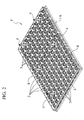
- a system for the transport of hatchery eggs E from the production site to an incubator comprises a series of egg-setter trays 1 directly stacked on one another, for example in two columns set alongside one another, on a pallet 2.
- the two columns set alongside one another are represented with a different number of trays 1 only for greater clarity of illustration in so far as normally said columns prepared for transport on the pallet 2 will typically comprise an equal number of trays 1.
- each tray 1 consists of a monolithic quadrangular body, preferably made of moulded plastic material, having a generally plane base la and a plurality of cells 3, that are to receive the eggs E, arranged in parallel rows at the sides of the body. Typically, ten rows of fifteen cells each can be provided for containing a total of 150 eggs.
- the tray 1 is formed with appendages 4 projecting upwards and having a tapered shape.
- appendages 4 projecting upwards and having a tapered shape.
- three pairs of projecting appendages 4 are provided, set at the same distance from one another and set asymmetrically with respect to a transverse centre plane of the tray 1.
- the asymmetry is such that, for example, between the intermediate pair of projecting appendages 4 and each lateral pair of projecting appendages 4, i.e., the pair located towards one side and the pair located towards the opposite side of the tray 1, there are six cells 3 for each row, whilst between the other sides of the tray 1 and the corresponding pair of lateral projecting appendages 4 there are two cells 3 on one side of the tray and just one cell 3 on the opposite side.
- the projecting appendages 4 are formed underneath with respective tapered cavities 5 having a shape complementary to that of their top portions.
- each tray 1 formed along one of its major sides, but not along the other, are identification marks 6, for example in the form of medicine-relief or bas-relief impressions, having the function of enabling immediate identification of the angular orientation in the horizontal plane of the tray 1 in a first position, where said impressions 6 are set facing an observer, or else in a second position, namely, rotated through 180° with respect to the first, where said impressions 6 are on the side facing away from the observer.
- This arrangement has the function of facilitating stacking of the trays 1, with the modalities clarified in what follows, also with the use of mechanized equipment provided with photoelectric-cell detection or camera-vision systems, or the like.
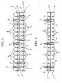
- Figures 3 and 4 exemplify the modalities of stacking of two trays 1 according to the invention directly set on top of one another according to two different configurations, namely, a configuration for containing and transporting the eggs E ( Figure 3 ) and a configuration where the eggs E are absent ( Figure 4 ).
- Figure 3 a configuration for containing and transporting the eggs E
- Figure 4 a configuration where the eggs E are absent
- the projecting appendages 4 of the bottom tray 1 are staggered with respect to those of the top tray 1 in the way represented in Figure 3 .
- the impressions 6 of one of the two trays 1, for example the top one are set facing a front side of the stack, whereas the reference impressions 6 of the other tray 1, for example the top one, are set facing the opposite side.
- the trays 1 containing the eggs E and thus stacked on top of one another can be simply rested on the pallet 2 so as to form the two stacks set alongside one another, as represented in Figure 1 .
- the pallet 2, as represented in Figure 5 can be conveniently formed at the top with peripheral projecting walls 7, formed integrally at the moment of production of the pallet 2 by moulding of plastic material.
- the trays 1 are instead positioned in the condition where they are set close to one another, as represented in Figure 4 , in the same angular position, i.e., with the respective reference impressions 6 facing the same way.
- the projecting appendages 4 of the bottom tray 1 are aligned and centred with respect to the projecting appendages 4 of the top tray 1, engaging at the top within the cavities 5 of the former.
- the distance between the two trays 1 set on top of one another can be reduced from approximately 70 mm with respect to the condition represented in Figure 3 , in the presence of the eggs E, to approximately 30 mm in the absence of the eggs E so as to facilitate storage of the trays on the site where the eggs are produced and facilitate transport during return from the site where the eggs E are incubated to the production site.
- the stacks of trays 1 can be positioned as described previously on the pallet 2 and thus be easily handled using a fork-lift truck for loading on the transport vehicle to be sent to the hatchery site and subsequent unloading and transfer to the incubators, thus avoiding the use of traditional metal supports or frames with wheels that are currently employed.
- both the steps of stacking on the pallet 2 and the operations of picking up of the trays 1 from the pallet 2 for their transfer to the incubators can be performed, as has been said, in a mechanized and automatic way.
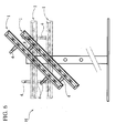
- the incubator H On place the incubator H on the frame (represented schematically in Figure 6 ) the trays 1 must be repositioned one after another all in the same angular position, thus aligning the respective projecting appendages 4 with respect to one another.
- the trays 1 will thus be set on top of one another and separated by the distancing imposed by the pitch of the incubator, which is typically in the region of 105 mm.
- the frame of the incubator H is prearranged to cause the trays 1 thus placed to rotate alternately to one side and to the other, in the way represented by a solid line in Figure 6 , passing through the horizontal position represented by a dashed line in the same figure.
- the height of the projecting appendages 4 is chosen, according to the invention, in such a way that during these movements of rotation there is no interference between each tray 1 and the corresponding underlying tray 1 in so far as the tops of the projecting appendages 4 of the underlying tray 1 can fit, without contact, between corresponding cells 3 of the overlying tray 1.
Description
- The present invention relates in general to the transport of hatchery eggs from the production site to an incubator.
- More in particular the invention regards an egg-setter tray that can be used both during transport and in the course of the process of incubation of the eggs, of the type traditionally comprising a generally quadrangular body formed with parallel rows of cells for containing the eggs.
- For the transport of trays of this sort according to the known art, one example of which is disclosed and illustrated in
US-4558661A , it is currently normal practice to provide purposely designed metal supports or frames, normally equipped with wheels, within which the trays are inserted in a condition where they are set on top of one another, like drawers, for their transfer on board lorries and transport to the hatchery plants. - Supports of this sort, in addition to being cumbersome and heavy, involve difficulties of handling during the operations of loading on and unloading off the lorry, also as regards the operations of introduction and extraction of the trays into/from the supports and their subsequent placing within the incubators.
- The object of the present invention is to overcome the aforesaid drawbacks and to provide an egg-setter tray that does not require the use of a metal support or frame for transport from the production site to the hatchery, thus rendering more convenient both the operations of loading the trays on and unloading them off the transport vehicle and the operation of placing them in the incubator, also enabling mechanization and automation of said operations.
- According to the invention, the above object is achieved thanks to an egg-setter tray of the type defined at the start, the main characteristic of which lies in the fact that it has appendages projecting upwards to engage directly a similar overlying tray selectively in a condition where said trays are set close to one another when they are stacked in the same angular position or in a condition where said trays are set at a distance apart when they are stacked in angular positions that are different from one another, mutually turned 180°.
- Thanks to this arrangement, the trays according to the invention can be stacked directly on top of one another both in the condition where they are set at a distance apart in the presence of the eggs, and in the condition where they are set close to one another in the absence of the eggs, in this case with less encumbrance. The transport of the trays thus stacked avoids recourse to the traditional metal supports or frames for transport, which can be replaced by simple pallets on which the stacks of trays, for example set in pairs alongside one another, rest.
- Conveniently, the projecting appendages of the tray are set in pairs asymmetrically with respect to the centre of the body and are hollow underneath. When the tray is set on top of a similar tray with the two trays set in the same angular position, the appendages of the bottom tray engage within the cavities of the appendages of the top tray. In this way, the distance between the two trays set on top of one another can be reduced from approximately 70 mm, corresponding to the condition where they are set at a distance apart in the presence of the eggs within the cells, to approximately 30 mm in the absence of the eggs, which enables minimization of the encumbrance in the condition of storage of the trays at the production site and of subsequent transport for return of the empty trays from the hatchery to the production site.
- The subject of the invention is also a transport system that uses a plurality of trays of this sort in the stacked condition and a pallet, typically made of moulded plastic material, on which the stacked trays are rested, for example, in two columns set alongside one another for handling thereof.
- The invention will now be described in detail with reference to the annexed drawings, which are provided purely by way of non-limiting example and in which:
-
Figure 1 is a schematic and partial perspective view that shows a transport system that uses egg-setter trays according to the invention; -
Figure 2 is a perspective view of one of the trays; -
Figure 3 is a longitudinal vertical cross-sectional view that shows a first condition of stacking of a pair of trays, in the presence of the eggs; -
Figure 4 is a view similar to that ofFigure 3 illustrating a second condition of stacking of two trays, in the absence of the eggs, -
Figure 5 is a perspective view at a larger scale that shows the pallet of the system for transport of the trays according to the invention; and -
Figure 6 is a schematic view in elevation that shows a pair of trays according to the invention in the condition where they are installed in an incubator. - With initial reference to
Figure 1 , a system for the transport of hatchery eggs E from the production site to an incubator, the supporting frame of which is represented schematically and designated as a whole by H inFigure 6 , comprises a series of egg-setter trays 1 directly stacked on one another, for example in two columns set alongside one another, on a pallet 2. InFigure 1 , the two columns set alongside one another are represented with a different number oftrays 1 only for greater clarity of illustration in so far as normally said columns prepared for transport on the pallet 2 will typically comprise an equal number oftrays 1. - With reference now in greater detail to
Figure 2 , eachtray 1 consists of a monolithic quadrangular body, preferably made of moulded plastic material, having a generally plane base la and a plurality ofcells 3, that are to receive the eggs E, arranged in parallel rows at the sides of the body. Typically, ten rows of fifteen cells each can be provided for containing a total of 150 eggs. - According to the peculiar characteristic of the invention, the
tray 1 is formed withappendages 4 projecting upwards and having a tapered shape. In the case of the example illustrated, three pairs ofprojecting appendages 4 are provided, set at the same distance from one another and set asymmetrically with respect to a transverse centre plane of thetray 1. As it can be seen in greater detail inFigures 3 and 4 , the asymmetry is such that, for example, between the intermediate pair ofprojecting appendages 4 and each lateral pair ofprojecting appendages 4, i.e., the pair located towards one side and the pair located towards the opposite side of thetray 1, there are sixcells 3 for each row, whilst between the other sides of thetray 1 and the corresponding pair oflateral projecting appendages 4 there are twocells 3 on one side of the tray and just onecell 3 on the opposite side. - As it can also be clearly seen in
Figures 3 and 4 , theprojecting appendages 4 are formed underneath with respectivetapered cavities 5 having a shape complementary to that of their top portions. - A further characteristic of each
tray 1 is that formed along one of its major sides, but not along the other, areidentification marks 6, for example in the form of haut-relief or bas-relief impressions, having the function of enabling immediate identification of the angular orientation in the horizontal plane of thetray 1 in a first position, where saidimpressions 6 are set facing an observer, or else in a second position, namely, rotated through 180° with respect to the first, where saidimpressions 6 are on the side facing away from the observer. This arrangement has the function of facilitating stacking of thetrays 1, with the modalities clarified in what follows, also with the use of mechanized equipment provided with photoelectric-cell detection or camera-vision systems, or the like. -
Figures 3 and 4 exemplify the modalities of stacking of twotrays 1 according to the invention directly set on top of one another according to two different configurations, namely, a configuration for containing and transporting the eggs E (Figure 3 ) and a configuration where the eggs E are absent (Figure 4 ). Obviously, the arrangement illustrated, described hereinafter, will be repeated identically for each pair ofcontiguous trays 1 set on top of one another. - In the case of
Figure 3 , i.e., as has been said in the presence of the eggs E within thecells 3 of thetrays 1, the latter are directly rested on top of one another in a condition where they are set at a distance apart and where the tops of theprojecting appendages 4 of thebottom tray 1 come to bear, from beneath, upon the bases ofcorresponding cells 3 of thetop tray 1. To obtain this, the twotrays 1 are set in angular positions that are different from one another, where one is turned 180° in its own plane of lie with respect to the other. Thanks to the asymmetrical arrangement of theprojecting appendages 4, when the twotrays 1 are stacked in said mutually opposite angular positions, theprojecting appendages 4 of thebottom tray 1 are staggered with respect to those of thetop tray 1 in the way represented inFigure 3 . In this case, theimpressions 6 of one of the twotrays 1, for example the top one, are set facing a front side of the stack, whereas thereference impressions 6 of theother tray 1, for example the top one, are set facing the opposite side. - With this arrangement, the
trays 1 containing the eggs E and thus stacked on top of one another can be simply rested on the pallet 2 so as to form the two stacks set alongside one another, as represented inFigure 1 . In order to enable a convenient and stable positioning of the stacks oftrays 1, the pallet 2, as represented inFigure 5 , can be conveniently formed at the top with peripheral projectingwalls 7, formed integrally at the moment of production of the pallet 2 by moulding of plastic material. - In the absence of the eggs E within the
cells 3, thetrays 1 are instead positioned in the condition where they are set close to one another, as represented inFigure 4 , in the same angular position, i.e., with therespective reference impressions 6 facing the same way. In this case, theprojecting appendages 4 of thebottom tray 1 are aligned and centred with respect to theprojecting appendages 4 of thetop tray 1, engaging at the top within thecavities 5 of the former. In this way, the distance between the twotrays 1 set on top of one another can be reduced from approximately 70 mm with respect to the condition represented inFigure 3 , in the presence of the eggs E, to approximately 30 mm in the absence of the eggs E so as to facilitate storage of the trays on the site where the eggs are produced and facilitate transport during return from the site where the eggs E are incubated to the production site. - In the condition illustrated in
Figure 3 where the trays are stacked on one another in the presence of the eggs E, the stacks oftrays 1 can be positioned as described previously on the pallet 2 and thus be easily handled using a fork-lift truck for loading on the transport vehicle to be sent to the hatchery site and subsequent unloading and transfer to the incubators, thus avoiding the use of traditional metal supports or frames with wheels that are currently employed. - Thanks to the presence of the
reference impressions 6, both the steps of stacking on the pallet 2 and the operations of picking up of thetrays 1 from the pallet 2 for their transfer to the incubators can be performed, as has been said, in a mechanized and automatic way. To place the incubator H on the frame (represented schematically inFigure 6 ) thetrays 1 must be repositioned one after another all in the same angular position, thus aligning therespective projecting appendages 4 with respect to one another. Thetrays 1 will thus be set on top of one another and separated by the distancing imposed by the pitch of the incubator, which is typically in the region of 105 mm. In a way in itself known, the frame of the incubator H is prearranged to cause thetrays 1 thus placed to rotate alternately to one side and to the other, in the way represented by a solid line inFigure 6 , passing through the horizontal position represented by a dashed line in the same figure. As may be seen inFigure 6 , the height of theprojecting appendages 4 is chosen, according to the invention, in such a way that during these movements of rotation there is no interference between eachtray 1 and the correspondingunderlying tray 1 in so far as the tops of theprojecting appendages 4 of theunderlying tray 1 can fit, without contact, betweencorresponding cells 3 of theoverlying tray 1. - Of course, the details of construction and the embodiments may vary widely with respect to what has been described and illustrated herein, without thereby departing from the scope of the present invention as defined in ensuing claims.
Claims (9)
- An egg-setter tray (1) for the transport of hatchery eggs (E) from the production site to an incubator (H) in a condition where said tray (1) is stacked together with similar trays (1), said tray (1) comprising a generally quadrangular body formed with parallel rows of cells (3) for containing the eggs (E) and being characterized in that it has appendages (4) projecting upwards to engage directly a similar overlying tray (1), selectively in a condition where the trays are set close to one another when said tray (1) and said overlying tray (1) are set in the same angular position, or in a condition where the trays are set at a distance apart when said tray (1) and said overlying tray (1) are set in angular positions different from one another, mutually turned 180°.
- The tray according to Claim 1, characterized in that said projecting appendages (4) are provided in pairs located asymmetrically with respect to the centre of the body of the tray (1).
- The tray according to Claim 2, characterized in that said projecting appendages (4) are hollow underneath and in that when two trays (1) are set on top of one another in said same angular position the projecting appendages (4) of the bottom tray engage within the cavities (5) of the projecting appendages (4) of the top tray.
- The tray according to any one of Claims the preceding claims, characterized in that said projecting appendages (4) project from the tray (1) at such a height that when trays (1) set on top of one another in an incubator (H) are oscillated simultaneously from a horizontal position to an inclined position, the projecting appendages (4) of each underlying tray do not interfere with the respective overlying tray.
- The tray according to one or more of the preceding claims, characterized in that said projecting appendages (4) have a tapered shape.
- The tray according to one or more of the preceding claims, characterized in that identification means (6) are provided on one side of the body for enabling said side to be visually distinguished from the opposite side.
- A system for the transport of hatchery eggs (E) from the production site to an incubator (H), characterized in that it uses stacks of trays (1) set on top of one another according to one or more of the preceding claims, and a pallet (2) on which the stacks of said trays (1) are to be rested.
- The transport system according to Claim 7, characterized in that said pallet (2) is designed to receive two rows set alongside one another of said trays (1) stacked on top of one another.
- The transport system according to Claim 7 or Claim 8, characterized in that said pallet is formed integrally with peripheral projecting walls (7).
Applications Claiming Priority (2)
| Application Number | Priority Date | Filing Date | Title |
|---|---|---|---|
| ITTO2010A000515A IT1401004B1 (en) | 2010-06-15 | 2010-06-15 | EGG TRAY AND TRANSPORT SYSTEM THAT USES THIS TRAY |
| PCT/IB2011/052116 WO2011158140A1 (en) | 2010-06-15 | 2011-05-13 | Egg-setter tray, and transport system that uses said tray |
Publications (2)
| Publication Number | Publication Date |
|---|---|
| EP2582229A1 EP2582229A1 (en) | 2013-04-24 |
| EP2582229B1 true EP2582229B1 (en) | 2014-06-25 |
Family
ID=43416227
Family Applications (1)
| Application Number | Title | Priority Date | Filing Date |
|---|---|---|---|
| EP11727775.6A Active EP2582229B1 (en) | 2010-06-15 | 2011-05-13 | Egg-setter tray, and transport system that uses said tray |
Country Status (3)
| Country | Link |
|---|---|
| EP (1) | EP2582229B1 (en) |
| IT (1) | IT1401004B1 (en) |
| WO (1) | WO2011158140A1 (en) |
Families Citing this family (2)
| Publication number | Priority date | Publication date | Assignee | Title |
|---|---|---|---|---|
| BE1025719B1 (en) | 2017-11-16 | 2019-06-24 | Columbus Besloten Vennootschap | Improved hatching process of eggs in hatcheries. |
| IT202100005465A1 (en) * | 2021-03-09 | 2022-09-09 | Lubing System S R L | ACCESSORY FOR EGG TRAY SUPPORTS INTENDED FOR USE IN EGG INCUBATORS |
Family Cites Families (4)
| Publication number | Priority date | Publication date | Assignee | Title |
|---|---|---|---|---|
| US3147738A (en) * | 1961-08-11 | 1964-09-08 | Rockwood & Co | Egg incubating tray with rack and pallet |
| GB1334330A (en) * | 1972-04-14 | 1973-10-17 | Noguchi H | Plastics trays for eggs |
| US3817215A (en) * | 1973-05-16 | 1974-06-18 | G Levin | Egg incubating tray with rack and carrier |
| US4558661A (en) * | 1980-02-22 | 1985-12-17 | The Marmon Group, Inc. | Egg holding flat |
-
2010
- 2010-06-15 IT ITTO2010A000515A patent/IT1401004B1/en active
-
2011
- 2011-05-13 WO PCT/IB2011/052116 patent/WO2011158140A1/en active Application Filing
- 2011-05-13 EP EP11727775.6A patent/EP2582229B1/en active Active
Also Published As
| Publication number | Publication date |
|---|---|
| ITTO20100515A1 (en) | 2011-12-16 |
| IT1401004B1 (en) | 2013-07-05 |
| WO2011158140A1 (en) | 2011-12-22 |
| EP2582229A1 (en) | 2013-04-24 |
Similar Documents
| Publication | Publication Date | Title |
|---|---|---|
| ES2373675T3 (en) | LOAD DEVICE FOR LOAD SUPPORTS. | |
| US6530476B1 (en) | Pallet stacking device | |
| ES2270206T4 (en) | Automated system and procedure for storing and picking items | |
| CN100519372C (en) | Device for stacking and unstacking objects | |
| NO344310B1 (en) | Automated storage and retrieval system comprising a three dimensional grid, container-handling vehicle and method of retrieving at least one storage container from the storage 40 storage and retrieval system | |
| WO2003101259A1 (en) | Modular rack | |
| US6032801A (en) | Pallet system | |
| NO343387B1 (en) | A storage bin and storage bin system | |
| CN112693800A (en) | Temporary storage laminate, temporary storage rack, goods shelf and storage device | |
| EP2582229B1 (en) | Egg-setter tray, and transport system that uses said tray | |
| US20120031787A1 (en) | Package for shipping and storing photovoltaic panel products | |
| ES2409459B1 (en) | Automated system to classify and palletize merchandise boxes and procedure for palletizing boxes of different sizes in the same pallet | |
| US20120317929A1 (en) | Cell tray, use thereof and method for handling containers | |
| US20210139199A1 (en) | Dairy tray system | |
| US4802588A (en) | Plant grow and transport pallet | |
| IL36576A (en) | Sample vial tray and a method for loading and unloading the tray | |
| JPH072532B2 (en) | Picking method | |
| CN202439907U (en) | Pallet capable of forking off cargo | |
| CN205872729U (en) | Egg holds in palm turnaround system | |
| EP0011482A1 (en) | Improvements in trays for containing eggs, fruit or other articles | |
| WO2007039511A1 (en) | Method for lifting up punnets containing horticultural products from the corresponding conveyance trays | |
| CN215623443U (en) | Plastic uptake tray for special-shaped electronic device | |
| CN217599851U (en) | Stacking disc and stacking machine | |
| US3176864A (en) | Method of barrel loading | |
| US3964617A (en) | Arrangement for the stacking in a space-saving manner of tetrahedral packing units in a prismatic collective container |
Legal Events
| Date | Code | Title | Description |
|---|---|---|---|
| PUAI | Public reference made under article 153(3) epc to a published international application that has entered the european phase |
Free format text: ORIGINAL CODE: 0009012 |
|
| 17P | Request for examination filed |
Effective date: 20121116 |
|
| AK | Designated contracting states |
Kind code of ref document: A1 Designated state(s): AL AT BE BG CH CY CZ DE DK EE ES FI FR GB GR HR HU IE IS IT LI LT LU LV MC MK MT NL NO PL PT RO RS SE SI SK SM TR |
|
| RAP1 | Party data changed (applicant data changed or rights of an application transferred) |
Owner name: TWINPACK B.V. |
|
| RAP1 | Party data changed (applicant data changed or rights of an application transferred) |
Owner name: GIORDANO POULTRY-PLAST S.P.A. Owner name: TWINPACK B.V. |
|
| DAX | Request for extension of the european patent (deleted) | ||
| GRAP | Despatch of communication of intention to grant a patent |
Free format text: ORIGINAL CODE: EPIDOSNIGR1 |
|
| INTG | Intention to grant announced |
Effective date: 20131206 |
|
| GRAS | Grant fee paid |
Free format text: ORIGINAL CODE: EPIDOSNIGR3 |
|
| GRAA | (expected) grant |
Free format text: ORIGINAL CODE: 0009210 |
|
| AK | Designated contracting states |
Kind code of ref document: B1 Designated state(s): AL AT BE BG CH CY CZ DE DK EE ES FI FR GB GR HR HU IE IS IT LI LT LU LV MC MK MT NL NO PL PT RO RS SE SI SK SM TR |
|
| REG | Reference to a national code |
Ref country code: GB Ref legal event code: FG4D |
|
| REG | Reference to a national code |
Ref country code: CH Ref legal event code: EP |
|
| REG | Reference to a national code |
Ref country code: AT Ref legal event code: REF Ref document number: 674006 Country of ref document: AT Kind code of ref document: T Effective date: 20140715 |
|
| REG | Reference to a national code |
Ref country code: IE Ref legal event code: FG4D |
|
| REG | Reference to a national code |
Ref country code: DE Ref legal event code: R096 Ref document number: 602011007986 Country of ref document: DE Effective date: 20140731 |
|
| PG25 | Lapsed in a contracting state [announced via postgrant information from national office to epo] |
Ref country code: FI Free format text: LAPSE BECAUSE OF FAILURE TO SUBMIT A TRANSLATION OF THE DESCRIPTION OR TO PAY THE FEE WITHIN THE PRESCRIBED TIME-LIMIT Effective date: 20140625 Ref country code: LT Free format text: LAPSE BECAUSE OF FAILURE TO SUBMIT A TRANSLATION OF THE DESCRIPTION OR TO PAY THE FEE WITHIN THE PRESCRIBED TIME-LIMIT Effective date: 20140625 Ref country code: CY Free format text: LAPSE BECAUSE OF FAILURE TO SUBMIT A TRANSLATION OF THE DESCRIPTION OR TO PAY THE FEE WITHIN THE PRESCRIBED TIME-LIMIT Effective date: 20140625 Ref country code: NO Free format text: LAPSE BECAUSE OF FAILURE TO SUBMIT A TRANSLATION OF THE DESCRIPTION OR TO PAY THE FEE WITHIN THE PRESCRIBED TIME-LIMIT Effective date: 20140925 Ref country code: GR Free format text: LAPSE BECAUSE OF FAILURE TO SUBMIT A TRANSLATION OF THE DESCRIPTION OR TO PAY THE FEE WITHIN THE PRESCRIBED TIME-LIMIT Effective date: 20140926 |
|
| REG | Reference to a national code |
Ref country code: NL Ref legal event code: T3 |
|
| REG | Reference to a national code |
Ref country code: AT Ref legal event code: MK05 Ref document number: 674006 Country of ref document: AT Kind code of ref document: T Effective date: 20140625 |
|
| REG | Reference to a national code |
Ref country code: LT Ref legal event code: MG4D |
|
| PG25 | Lapsed in a contracting state [announced via postgrant information from national office to epo] |
Ref country code: LV Free format text: LAPSE BECAUSE OF FAILURE TO SUBMIT A TRANSLATION OF THE DESCRIPTION OR TO PAY THE FEE WITHIN THE PRESCRIBED TIME-LIMIT Effective date: 20140625 Ref country code: RS Free format text: LAPSE BECAUSE OF FAILURE TO SUBMIT A TRANSLATION OF THE DESCRIPTION OR TO PAY THE FEE WITHIN THE PRESCRIBED TIME-LIMIT Effective date: 20140625 Ref country code: HR Free format text: LAPSE BECAUSE OF FAILURE TO SUBMIT A TRANSLATION OF THE DESCRIPTION OR TO PAY THE FEE WITHIN THE PRESCRIBED TIME-LIMIT Effective date: 20140625 Ref country code: SE Free format text: LAPSE BECAUSE OF FAILURE TO SUBMIT A TRANSLATION OF THE DESCRIPTION OR TO PAY THE FEE WITHIN THE PRESCRIBED TIME-LIMIT Effective date: 20140625 |
|
| PG25 | Lapsed in a contracting state [announced via postgrant information from national office to epo] |
Ref country code: RO Free format text: LAPSE BECAUSE OF FAILURE TO SUBMIT A TRANSLATION OF THE DESCRIPTION OR TO PAY THE FEE WITHIN THE PRESCRIBED TIME-LIMIT Effective date: 20140625 Ref country code: SK Free format text: LAPSE BECAUSE OF FAILURE TO SUBMIT A TRANSLATION OF THE DESCRIPTION OR TO PAY THE FEE WITHIN THE PRESCRIBED TIME-LIMIT Effective date: 20140625 Ref country code: PT Free format text: LAPSE BECAUSE OF FAILURE TO SUBMIT A TRANSLATION OF THE DESCRIPTION OR TO PAY THE FEE WITHIN THE PRESCRIBED TIME-LIMIT Effective date: 20141027 Ref country code: ES Free format text: LAPSE BECAUSE OF FAILURE TO SUBMIT A TRANSLATION OF THE DESCRIPTION OR TO PAY THE FEE WITHIN THE PRESCRIBED TIME-LIMIT Effective date: 20140625 Ref country code: CZ Free format text: LAPSE BECAUSE OF FAILURE TO SUBMIT A TRANSLATION OF THE DESCRIPTION OR TO PAY THE FEE WITHIN THE PRESCRIBED TIME-LIMIT Effective date: 20140625 Ref country code: EE Free format text: LAPSE BECAUSE OF FAILURE TO SUBMIT A TRANSLATION OF THE DESCRIPTION OR TO PAY THE FEE WITHIN THE PRESCRIBED TIME-LIMIT Effective date: 20140625 |
|
| PG25 | Lapsed in a contracting state [announced via postgrant information from national office to epo] |
Ref country code: PL Free format text: LAPSE BECAUSE OF FAILURE TO SUBMIT A TRANSLATION OF THE DESCRIPTION OR TO PAY THE FEE WITHIN THE PRESCRIBED TIME-LIMIT Effective date: 20140625 Ref country code: AT Free format text: LAPSE BECAUSE OF FAILURE TO SUBMIT A TRANSLATION OF THE DESCRIPTION OR TO PAY THE FEE WITHIN THE PRESCRIBED TIME-LIMIT Effective date: 20140625 Ref country code: IS Free format text: LAPSE BECAUSE OF FAILURE TO SUBMIT A TRANSLATION OF THE DESCRIPTION OR TO PAY THE FEE WITHIN THE PRESCRIBED TIME-LIMIT Effective date: 20141025 |
|
| REG | Reference to a national code |
Ref country code: DE Ref legal event code: R097 Ref document number: 602011007986 Country of ref document: DE |
|
| PG25 | Lapsed in a contracting state [announced via postgrant information from national office to epo] |
Ref country code: DK Free format text: LAPSE BECAUSE OF FAILURE TO SUBMIT A TRANSLATION OF THE DESCRIPTION OR TO PAY THE FEE WITHIN THE PRESCRIBED TIME-LIMIT Effective date: 20140625 |
|
| PLBE | No opposition filed within time limit |
Free format text: ORIGINAL CODE: 0009261 |
|
| STAA | Information on the status of an ep patent application or granted ep patent |
Free format text: STATUS: NO OPPOSITION FILED WITHIN TIME LIMIT |
|
| 26N | No opposition filed |
Effective date: 20150326 |
|
| PG25 | Lapsed in a contracting state [announced via postgrant information from national office to epo] |
Ref country code: BE Free format text: LAPSE BECAUSE OF FAILURE TO SUBMIT A TRANSLATION OF THE DESCRIPTION OR TO PAY THE FEE WITHIN THE PRESCRIBED TIME-LIMIT Effective date: 20140625 |
|
| REG | Reference to a national code |
Ref country code: DE Ref legal event code: R097 Ref document number: 602011007986 Country of ref document: DE Effective date: 20150326 |
|
| PG25 | Lapsed in a contracting state [announced via postgrant information from national office to epo] |
Ref country code: SI Free format text: LAPSE BECAUSE OF FAILURE TO SUBMIT A TRANSLATION OF THE DESCRIPTION OR TO PAY THE FEE WITHIN THE PRESCRIBED TIME-LIMIT Effective date: 20140625 |
|
| REG | Reference to a national code |
Ref country code: CH Ref legal event code: PL |
|
| PG25 | Lapsed in a contracting state [announced via postgrant information from national office to epo] |
Ref country code: LU Free format text: LAPSE BECAUSE OF FAILURE TO SUBMIT A TRANSLATION OF THE DESCRIPTION OR TO PAY THE FEE WITHIN THE PRESCRIBED TIME-LIMIT Effective date: 20150513 Ref country code: LI Free format text: LAPSE BECAUSE OF NON-PAYMENT OF DUE FEES Effective date: 20150531 Ref country code: MC Free format text: LAPSE BECAUSE OF FAILURE TO SUBMIT A TRANSLATION OF THE DESCRIPTION OR TO PAY THE FEE WITHIN THE PRESCRIBED TIME-LIMIT Effective date: 20140625 Ref country code: CH Free format text: LAPSE BECAUSE OF NON-PAYMENT OF DUE FEES Effective date: 20150531 |
|
| REG | Reference to a national code |
Ref country code: IE Ref legal event code: MM4A |
|
| REG | Reference to a national code |
Ref country code: FR Ref legal event code: PLFP Year of fee payment: 6 |
|
| PG25 | Lapsed in a contracting state [announced via postgrant information from national office to epo] |
Ref country code: IE Free format text: LAPSE BECAUSE OF NON-PAYMENT OF DUE FEES Effective date: 20150513 |
|
| PG25 | Lapsed in a contracting state [announced via postgrant information from national office to epo] |
Ref country code: MT Free format text: LAPSE BECAUSE OF FAILURE TO SUBMIT A TRANSLATION OF THE DESCRIPTION OR TO PAY THE FEE WITHIN THE PRESCRIBED TIME-LIMIT Effective date: 20140625 |
|
| REG | Reference to a national code |
Ref country code: FR Ref legal event code: PLFP Year of fee payment: 7 |
|
| PG25 | Lapsed in a contracting state [announced via postgrant information from national office to epo] |
Ref country code: BG Free format text: LAPSE BECAUSE OF FAILURE TO SUBMIT A TRANSLATION OF THE DESCRIPTION OR TO PAY THE FEE WITHIN THE PRESCRIBED TIME-LIMIT Effective date: 20140625 Ref country code: SM Free format text: LAPSE BECAUSE OF FAILURE TO SUBMIT A TRANSLATION OF THE DESCRIPTION OR TO PAY THE FEE WITHIN THE PRESCRIBED TIME-LIMIT Effective date: 20140625 Ref country code: HU Free format text: LAPSE BECAUSE OF FAILURE TO SUBMIT A TRANSLATION OF THE DESCRIPTION OR TO PAY THE FEE WITHIN THE PRESCRIBED TIME-LIMIT; INVALID AB INITIO Effective date: 20110513 |
|
| REG | Reference to a national code |
Ref country code: FR Ref legal event code: PLFP Year of fee payment: 8 |
|
| PG25 | Lapsed in a contracting state [announced via postgrant information from national office to epo] |
Ref country code: MK Free format text: LAPSE BECAUSE OF FAILURE TO SUBMIT A TRANSLATION OF THE DESCRIPTION OR TO PAY THE FEE WITHIN THE PRESCRIBED TIME-LIMIT Effective date: 20140625 |
|
| PG25 | Lapsed in a contracting state [announced via postgrant information from national office to epo] |
Ref country code: AL Free format text: LAPSE BECAUSE OF FAILURE TO SUBMIT A TRANSLATION OF THE DESCRIPTION OR TO PAY THE FEE WITHIN THE PRESCRIBED TIME-LIMIT Effective date: 20140625 |
|
| PGFP | Annual fee paid to national office [announced via postgrant information from national office to epo] |
Ref country code: DE Payment date: 20200529 Year of fee payment: 10 |
|
| PGFP | Annual fee paid to national office [announced via postgrant information from national office to epo] |
Ref country code: GB Payment date: 20200528 Year of fee payment: 10 |
|
| PGFP | Annual fee paid to national office [announced via postgrant information from national office to epo] |
Ref country code: TR Payment date: 20210427 Year of fee payment: 11 |
|
| REG | Reference to a national code |
Ref country code: DE Ref legal event code: R119 Ref document number: 602011007986 Country of ref document: DE |
|
| GBPC | Gb: european patent ceased through non-payment of renewal fee |
Effective date: 20210513 |
|
| PG25 | Lapsed in a contracting state [announced via postgrant information from national office to epo] |
Ref country code: GB Free format text: LAPSE BECAUSE OF NON-PAYMENT OF DUE FEES Effective date: 20210513 Ref country code: DE Free format text: LAPSE BECAUSE OF NON-PAYMENT OF DUE FEES Effective date: 20211201 |
|
| PGFP | Annual fee paid to national office [announced via postgrant information from national office to epo] |
Ref country code: NL Payment date: 20220526 Year of fee payment: 12 |
|
| PGFP | Annual fee paid to national office [announced via postgrant information from national office to epo] |
Ref country code: IT Payment date: 20220511 Year of fee payment: 12 |
|
| PGFP | Annual fee paid to national office [announced via postgrant information from national office to epo] |
Ref country code: FR Payment date: 20230523 Year of fee payment: 13 |
|
| REG | Reference to a national code |
Ref country code: NL Ref legal event code: MM Effective date: 20230601 |
|
| PG25 | Lapsed in a contracting state [announced via postgrant information from national office to epo] |
Ref country code: NL Free format text: LAPSE BECAUSE OF NON-PAYMENT OF DUE FEES Effective date: 20230601 |