EP2582084A2 - Appareil et procédé de transmission et réception dýinformations rétroactives dans un système de communications mobile - Google Patents
Appareil et procédé de transmission et réception dýinformations rétroactives dans un système de communications mobile Download PDFInfo
- Publication number
- EP2582084A2 EP2582084A2 EP12188379.7A EP12188379A EP2582084A2 EP 2582084 A2 EP2582084 A2 EP 2582084A2 EP 12188379 A EP12188379 A EP 12188379A EP 2582084 A2 EP2582084 A2 EP 2582084A2
- Authority
- EP
- European Patent Office
- Prior art keywords
- feedback
- information
- cell
- csi
- cqi
- Prior art date
- Legal status (The legal status is an assumption and is not a legal conclusion. Google has not performed a legal analysis and makes no representation as to the accuracy of the status listed.)
- Granted
Links
- 238000000034 method Methods 0.000 title claims abstract description 63
- 238000010295 mobile communication Methods 0.000 title claims abstract description 39
- 230000005540 biological transmission Effects 0.000 claims abstract description 92
- 238000005259 measurement Methods 0.000 claims description 62
- 239000011159 matrix material Substances 0.000 claims description 3
- 229920006934 PMI Polymers 0.000 description 24
- 238000004891 communication Methods 0.000 description 16
- 230000001413 cellular effect Effects 0.000 description 14
- 230000011664 signaling Effects 0.000 description 8
- QHPJWPQRZMBKTG-UHFFFAOYSA-N ethyl 2-[2-methoxy-4-[(4-oxo-2-sulfanylidene-1,3-thiazolidin-5-ylidene)methyl]phenoxy]acetate Chemical compound C1=C(OC)C(OCC(=O)OCC)=CC=C1C=C1C(=O)NC(=S)S1 QHPJWPQRZMBKTG-UHFFFAOYSA-N 0.000 description 5
- 238000010586 diagram Methods 0.000 description 4
- 238000005516 engineering process Methods 0.000 description 4
- 230000006870 function Effects 0.000 description 3
- 230000008901 benefit Effects 0.000 description 2
- 230000015556 catabolic process Effects 0.000 description 2
- 238000006731 degradation reaction Methods 0.000 description 2
- 230000003044 adaptive effect Effects 0.000 description 1
- 230000002776 aggregation Effects 0.000 description 1
- 238000004220 aggregation Methods 0.000 description 1
- 230000008859 change Effects 0.000 description 1
- 230000007774 longterm Effects 0.000 description 1
- 238000007726 management method Methods 0.000 description 1
- 230000004048 modification Effects 0.000 description 1
- 238000012986 modification Methods 0.000 description 1
- 230000000737 periodic effect Effects 0.000 description 1
- 238000012913 prioritisation Methods 0.000 description 1
- 230000008569 process Effects 0.000 description 1
- 230000008054 signal transmission Effects 0.000 description 1
Images


Classifications
-
- H—ELECTRICITY
- H04—ELECTRIC COMMUNICATION TECHNIQUE
- H04L—TRANSMISSION OF DIGITAL INFORMATION, e.g. TELEGRAPHIC COMMUNICATION
- H04L5/00—Arrangements affording multiple use of the transmission path
- H04L5/003—Arrangements for allocating sub-channels of the transmission path
- H04L5/0048—Allocation of pilot signals, i.e. of signals known to the receiver
-
- H—ELECTRICITY
- H04—ELECTRIC COMMUNICATION TECHNIQUE
- H04B—TRANSMISSION
- H04B7/00—Radio transmission systems, i.e. using radiation field
- H04B7/02—Diversity systems; Multi-antenna system, i.e. transmission or reception using multiple antennas
- H04B7/04—Diversity systems; Multi-antenna system, i.e. transmission or reception using multiple antennas using two or more spaced independent antennas
- H04B7/06—Diversity systems; Multi-antenna system, i.e. transmission or reception using multiple antennas using two or more spaced independent antennas at the transmitting station
- H04B7/0613—Diversity systems; Multi-antenna system, i.e. transmission or reception using multiple antennas using two or more spaced independent antennas at the transmitting station using simultaneous transmission
- H04B7/0615—Diversity systems; Multi-antenna system, i.e. transmission or reception using multiple antennas using two or more spaced independent antennas at the transmitting station using simultaneous transmission of weighted versions of same signal
- H04B7/0619—Diversity systems; Multi-antenna system, i.e. transmission or reception using multiple antennas using two or more spaced independent antennas at the transmitting station using simultaneous transmission of weighted versions of same signal using feedback from receiving side
- H04B7/0621—Feedback content
- H04B7/0626—Channel coefficients, e.g. channel state information [CSI]
-
- H—ELECTRICITY
- H04—ELECTRIC COMMUNICATION TECHNIQUE
- H04B—TRANSMISSION
- H04B17/00—Monitoring; Testing
- H04B17/20—Monitoring; Testing of receivers
- H04B17/24—Monitoring; Testing of receivers with feedback of measurements to the transmitter
-
- H—ELECTRICITY
- H04—ELECTRIC COMMUNICATION TECHNIQUE
- H04B—TRANSMISSION
- H04B17/00—Monitoring; Testing
- H04B17/30—Monitoring; Testing of propagation channels
- H04B17/309—Measuring or estimating channel quality parameters
- H04B17/345—Interference values
-
- H—ELECTRICITY
- H04—ELECTRIC COMMUNICATION TECHNIQUE
- H04L—TRANSMISSION OF DIGITAL INFORMATION, e.g. TELEGRAPHIC COMMUNICATION
- H04L5/00—Arrangements affording multiple use of the transmission path
- H04L5/003—Arrangements for allocating sub-channels of the transmission path
- H04L5/0032—Distributed allocation, i.e. involving a plurality of allocating devices, each making partial allocation
- H04L5/0035—Resource allocation in a cooperative multipoint environment
-
- H—ELECTRICITY
- H04—ELECTRIC COMMUNICATION TECHNIQUE
- H04L—TRANSMISSION OF DIGITAL INFORMATION, e.g. TELEGRAPHIC COMMUNICATION
- H04L5/00—Arrangements affording multiple use of the transmission path
- H04L5/003—Arrangements for allocating sub-channels of the transmission path
- H04L5/0037—Inter-user or inter-terminal allocation
-
- H—ELECTRICITY
- H04—ELECTRIC COMMUNICATION TECHNIQUE
- H04L—TRANSMISSION OF DIGITAL INFORMATION, e.g. TELEGRAPHIC COMMUNICATION
- H04L5/00—Arrangements affording multiple use of the transmission path
- H04L5/003—Arrangements for allocating sub-channels of the transmission path
- H04L5/0053—Allocation of signaling, i.e. of overhead other than pilot signals
- H04L5/0057—Physical resource allocation for CQI
-
- H—ELECTRICITY
- H04—ELECTRIC COMMUNICATION TECHNIQUE
- H04L—TRANSMISSION OF DIGITAL INFORMATION, e.g. TELEGRAPHIC COMMUNICATION
- H04L5/00—Arrangements affording multiple use of the transmission path
- H04L5/003—Arrangements for allocating sub-channels of the transmission path
- H04L5/0058—Allocation criteria
- H04L5/0073—Allocation arrangements that take into account other cell interferences
-
- H—ELECTRICITY
- H04—ELECTRIC COMMUNICATION TECHNIQUE
- H04L—TRANSMISSION OF DIGITAL INFORMATION, e.g. TELEGRAPHIC COMMUNICATION
- H04L5/00—Arrangements affording multiple use of the transmission path
- H04L5/0091—Signaling for the administration of the divided path
-
- H—ELECTRICITY
- H04—ELECTRIC COMMUNICATION TECHNIQUE
- H04W—WIRELESS COMMUNICATION NETWORKS
- H04W24/00—Supervisory, monitoring or testing arrangements
-
- H—ELECTRICITY
- H04—ELECTRIC COMMUNICATION TECHNIQUE
- H04W—WIRELESS COMMUNICATION NETWORKS
- H04W72/00—Local resource management
- H04W72/20—Control channels or signalling for resource management
- H04W72/21—Control channels or signalling for resource management in the uplink direction of a wireless link, i.e. towards the network
-
- H—ELECTRICITY
- H04—ELECTRIC COMMUNICATION TECHNIQUE
- H04W—WIRELESS COMMUNICATION NETWORKS
- H04W72/00—Local resource management
- H04W72/50—Allocation or scheduling criteria for wireless resources
- H04W72/54—Allocation or scheduling criteria for wireless resources based on quality criteria
- H04W72/541—Allocation or scheduling criteria for wireless resources based on quality criteria using the level of interference
-
- H—ELECTRICITY
- H04—ELECTRIC COMMUNICATION TECHNIQUE
- H04L—TRANSMISSION OF DIGITAL INFORMATION, e.g. TELEGRAPHIC COMMUNICATION
- H04L5/00—Arrangements affording multiple use of the transmission path
- H04L5/0001—Arrangements for dividing the transmission path
- H04L5/0003—Two-dimensional division
- H04L5/0005—Time-frequency
- H04L5/0007—Time-frequency the frequencies being orthogonal, e.g. OFDM(A), DMT
-
- H—ELECTRICITY
- H04—ELECTRIC COMMUNICATION TECHNIQUE
- H04W—WIRELESS COMMUNICATION NETWORKS
- H04W88/00—Devices specially adapted for wireless communication networks, e.g. terminals, base stations or access point devices
- H04W88/02—Terminal devices
-
- H—ELECTRICITY
- H04—ELECTRIC COMMUNICATION TECHNIQUE
- H04W—WIRELESS COMMUNICATION NETWORKS
- H04W88/00—Devices specially adapted for wireless communication networks, e.g. terminals, base stations or access point devices
- H04W88/08—Access point devices
Definitions
- the present invention relates generally to a method and apparatus for generating feedback information in a cellular mobile communication system including a plurality of Base Stations (BSs), and more particularly, to a method and apparatus for transmitting and receiving feedback information in a Coordinated Multi-Point (CoMP) system, in which a plurality of BSs cooperate to support downlink transmission to a User Equipment (UE).
- BSs Base Stations
- CoMP Coordinated Multi-Point
- Mobile communication systems have been developing into high-speed, high-quality wireless packet data communication systems to provide data services and multimedia services beyond traditional voice-oriented services.
- HSDPA High Speed Downlink Packet Access
- HSUPA High Speed Uplink Packet Access
- 3GPP 3 rd Generation Partnership Project
- HRPD High Rate Packet Data
- IEEE Institute of Electrical and Electronics Engineers
- the 3G wireless packet data communication systems such as HSDPA, HSUPA and HRPD, use technologies such as Adaptive Modulation and Coding (AMC) and channel-sensitive scheduling to improve transmission efficiency.
- AMC Adaptive Modulation and Coding
- MCS Modulation and Coding Scheme
- the transmitter adjusts the amount of transmission data according to the channel state. That is, in a poor channel state, the transmitter reduces the amount of transmission data to decrease a reception error probability to a desired level. In a good channel state, the transmitter increases the amount of transmission data to increase the reception error probability to a desired level, thereby ensuring efficient information transmission.
- the transmitter selectively services a user having a superior channel state among several users, contributing to an increase in system capacity, compared to the case in which the transmitter allocates a channel to one user and services the user.
- Such an increase in system capacity is called 'multi-user diversity gain'.
- AMC is used together with Multiple Input Multiple Output (MIMO)
- MIMO Multiple Input Multiple Output
- a wireless packet data communication system adopting AMC takes into account the number of layers for MIMO transmission as well as a coding rate and a modulation scheme in determining an optimum data rate.
- Orthogonal Frequency Division Multiple Access is a technology that can increase capacity, as compared to Code Division Multiple Access (CDMA).
- CDMA Code Division Multiple Access
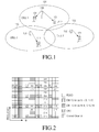
- FIG. 1 illustrates a cellular mobile communication system in which a Transmission (Tx)/Reception (Rx) antenna is included at the center in each cell.
- Tx Transmission
- Rx Radio
- a User Equipment receives a mobile communication service using the aforementioned techniques from a selected cell during a semi-static time period.
- the cellular mobile communication system includes three cells 100, 110 and 120 (Cell 1, Cell 2 and Cell 3).
- Cell 1 provides the mobile communication service to UEs 101 and 102 (UE 1 and UE 2)
- Cell 2 provides the mobile communication service to a UE 111 (UE 3)
- Cell 3 provides the mobile communication service to a UE 121 (UE 4).
- Antennas 130, 131 and 132 are included at the centers of the respective cells 100, 110, and 120.
- the antennas 130, 131, and 132 correspond to BSs or relays.
- UE 2 receiving the mobile communication service from Cell 1, is relatively far from the antenna 130, as compared to UE 1. Moreover, Cell 1 supports a relatively low data rate for UE 2 because UE 2 experiences severe interference from the antenna 132 at the center of Cell 3.
- RSs Reference Signals
- a UE measures a channel state between the UE and a BS using Channel State Information-Reference Signals (CSI-RSs) and feeds back channel state information to the BS.
- CSI-RSs Channel State Information-Reference Signals
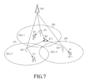
- FIG. 2 illustrates the positions of CSI-RSs transmitted from BSs to a UE in an LTE-A system.
- resources available in the LTE-A system are divided into equal-size Resource Blocks (RBs).
- the horizontal axis and vertical axis of the resources represent time and frequency, respectively.
- Signals for two CSI-RS antenna ports are transmitted in the resources of each of RBs 200 to 219. That is, the BS transmits two CSI-RSs for downlink measurement to the UE in the resources of the RBs 200.
- an RB at a different position is allocated to each cell and CSI-RSs are transmitted in the resources of the allocated RB.
- Cell 1 transmits CSI-RSs in the resources of the RBs 200
- Cell 2 transmits CSI-RSs in the resources of the RBs 205
- Cell 3 transmits CSI-RSs in the resources of the RBs 210.
- the reason for allocating different RBs (e.g., different time and frequency resources) for CSI-RS transmission to different cells is to prevent mutual interference between CSI-RSs from different cells.
- a UE estimates a downlink channel using CSI-RSs, generates a Rank Indicator (RI), a Channel Quality Indicator (CQI), and a Precoding Matrix Index (PMI) as CSI of the estimated downlink channel, and feeds back the CSI to a BS.
- RI Rank Indicator
- CQI Channel Quality Indicator
- PMI Precoding Matrix Index
- PUSCH Physical Uplink Control Channel
- the feedback timing of each piece of information in the four feedback modes is determined according to N pd ,N OFFSET,CQI , M RI , and N OFFSET,RI indicated by higher-layer signaling.
- the transmission period of a wCQI is N pd and the feedback timing of the wCQI is determined using a subframe offset of N OFFSET,CQI .
- the transmission period and offset of an RI are N pd ⁇ M RI and N OFFSET,CQI +N OFFSET,RI , respectively.
- Mode 1-1 and Mode 1-0 have the same feedback timing, however, a PMI is transmitted together with a wCQI at the transmitting timing of the wCQI in Mode 1-1.
- FIG. 3 illustrates the feedback timings of an RI, a wCQI, and a PMI in Mode 1-0 and Mode 1-1. Each transmission timing is represented as a subframe index.
- the feedback period and offset of an sCQI are N pd and N OFFSET,CQI , respectively.
- the feedback period and offset of a wCQI are H•N pd and N OFFSET,CQI , respectively.
- H J ⁇ K+1, where K is a value indicated by higher-layer signaling and J is a value determined by a system bandwidth. For instance, J is 3 for a 10-MHz system.
- K is a value indicated by higher-layer signaling
- J is a value determined by a system bandwidth.
- J is 3 for a 10-MHz system.
- the feedback period and offset of an RI are M RI •H•N pd and N OFFSET,CQI + N OFFSET,RI respectively.
- Mode 2-1 is the same as Mode 2-0 in feedback timing but different from Mode 2-0 in that a PMI is transmitted together with a wCQI at the transmission timing of the wCQI.
- the above-described feedback timings are set for 4 or fewer CSI-RS antenna ports.
- two PMIs are fed back, unlike the above cases.
- Mode 1-1 is further divided into two submodes.
- a first PMI is transmitted together with an RI and a second PMI is transmitted together with a wCQI in a first submode.
- the feedback period and offset of the RI and the first PMI are defined as M RI •N pd and N OFFSET,CQI +N OFFSET,RI , respectively and the feedback period and offset of the wCQI and the second PMI are defined as N pd and N OFFSET,CQI , respectively.
- a Precoding Type Indicator (PTI) is added in Mode 2-1.
- the PTI is transmitted together with an RI in a period of M RI •H•N pd with an offset of N OFFSET,CQI +N OFFSET,RI .
- first and second PMIs and a wCQI are feedback.
- the wCQI and the second PMI are transmitted at the same timing in a period of N pd with an offset of N OFFSET,CQI .
- the feedback period and offset of the first PMI are H ⁇ N pd and N OFFSET,CQI , respectively.
- H' is indicated by higher-layer signaling.
- the PTI is 1, the PRI and the RI are transmitted together and the wCQI and the second PMI are transmitted together.
- the sCQI is additionally fed back.
- the first PMI is not transmitted.
- the PTI and the RI have the same feedback period and offset as those of the PTI and RI in the case in which the PTI is 0.
- the feedback period and offset of the sCQI are defined as N pd and N OFFSET,CQI , respectively.
- the wCQI and the second PMI are fed back in a period of H ⁇ N pd with an offset of N OFFSET,CQI .
- H is the same as that for 4 CSI-RS antenna ports.
- the conventional CSI feedback technology is based on the premise that a UE transmits a single CSI feedback, without regard to a multi-CSI feedback situation for CoMP transmission, that is, simultaneous transmissions from a plurality of transmission points.
- the present invention has been made to solve the above-stated problems occurring in the prior art, and an aspect of the present invention provides a method and apparatus for transmitting and receiving feedback information in a mobile communication system.
- Another aspect of the embodiments of the present invention is to provide a multiChannel State Information (CSI) feedback method and apparatus for Coordinated Multi-Point (CoMP) transmission in a mobile communication system.
- CSI MultiChannel State Information
- CoMP Coordinated Multi-Point
- a method for transmitting feedback information by a User Equipment (UE) in a mobile communication system includes receiving information about at least one Channel State Information Reference Signal (CSI-RS); performing channel estimation based on the information about at least one CSI-RS; receiving information about at least one feedback; and transmitting a feedback including a channel estimation result using the information about at least one feedback, wherein the information about at least one feedback includes information about a transmission timing and a feedback mode for the feedback.
- CSI-RS Channel State Information Reference Signal
- a method for receiving feedback information by a central control device managing at least one cell in a mobile communication system includes transmitting information about at least one Channel State Information Reference Signal (CSI-RS) to a User Equipment (UE); transmitting information about at least one feedback to the UE; and receiving at least one feedback transmitted based on the information about at least one feedback from the UE, wherein the information about at least one feedback includes a channel estimation result generated based on the information about at least one CSI-RS and includes information about a transmission timing and a feedback mode for the at least one feedback.
- CSI-RS Channel State Information Reference Signal
- UE User Equipment
- a User Equipment (UE) in a mobile communication system includes a transmitter; a receiver for receiving information about at least one Channel State Information Reference Signal (CSI-RS) and information about at least one feedback; and a controller for performing channel estimation based on the information about at least one CSI-RS and, upon receipt of the information about at least one feedback, controlling the transmitter to transmit at least one feedback including a channel estimation result using the information about at least one feedback, wherein the information about at least one feedback includes information about a transmission timing and a feedback mode for the at least one feedback.
- CSI-RS Channel State Information Reference Signal
- a central control device managing at least one cell in a mobile communication system.
- the central control device includes a transmitter for transmitting information about at least one Channel State Information Reference Signal (CSI-RS) and information about at least one feedback to a User Equipment (UE); and a receiver for receiving at least one feedback transmitted based on the information about at least one feedback from the UE, wherein the information about at least one feedback includes a channel estimation result generated based on the information about at least one CSI-RS and includes a transmission timing and a feedback mode for the at least one feedback.
- CSI-RS Channel State Information Reference Signal
- UE User Equipment
- OFDM Orthogonal Frequency Division Multiplexing
- 3GPP 3 rd Generation Partnership Project
- EUTRA Evolved UMTS Terrestrial Radio Access
- a cellular mobile communication system includes a plurality of cells in a limited area. Each cell is provided with Base Station (BS) equipment controlling mobile communication within the cell.
- the BS equipment provides a mobile communication service to User Equipments (UEs) within the cell.
- UEs User Equipments
- a specific UE receives the mobile communication service only from one semi-statically determined cell. This system is called a non-Coordinated Multi-Point (CoMP) system.
- CoMP non-Coordinated Multi-Point
- the data rates of UEs within a cell vary based on their locations in the cell.
- a UE at a cell center generally has a high data rate, whereas a UE at a cell edge generally has a low data rate.
- the opposite concept of the non-CoMP system is a CoMP system.
- a CoMP system a plurality of cells coordinate data transmission to a UE located at a cell edge.
- a better-quality mobile communication service is provided to the UE, as compared to the non-CoMP system.
- An embodiment of the present invention provides a method and apparatus for transmitting feedback information in a CoMP system, taking into account Dynamic cell Selection (DS), Dynamic cell Selection with Dynamic Blanking (DS/DB), and Joint Transmission (JT).
- DS Dynamic cell Selection
- DS/DB Dynamic cell Selection with Dynamic Blanking
- JT Joint Transmission
- a UE measures a channel state on a cell basis and transmits feedback information related to the measured channel states to a BS.
- the BS then dynamically selects a cell that will transmit downlink data to the UE.
- JT is a technique of simultaneously transmitting data from a plurality of cells to a specific UE. That is, to overcome the problems, an embodiment of the present invention designs a feedback structure so as to efficiently apply DS, DS/DB, or JT to the LTE-A system.
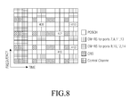
- FIG. 7 illustrates the configuration of a cellular mobile communication system according to an embodiment of the present invention.
- the cellular mobile communication system includes three cells 300, 310 and 320 (Cell 1, Cell 2 and Cell 3).
- a cell refers to a data transmission area that a specific transmission point can service.
- Each transmission point is a Remote Radio Head (RRH) sharing a cell Identifier (ID) with a macro BS within a macro area or a macrocell or picocell having a different cell ID.
- RRH Remote Radio Head
- ID cell Identifier
- a central control device is a device that can transmit and receive data to and from a UE and process the transmission and received data. If each transmission point is an RRH sharing a cell ID with a macro BS, the macro BS is called a central control device. However, if each transmission point is a macrocell or a picocell having a different cell ID, a device that manages cells integrally is called a central control device.
- first, third and fourth UEs 301, 311 and 321 receive data from their nearest cells among Cell 1, Cell 2 and Cell 3 and 320 and a second UE 302 (UE 2) receives data from Cell 1, Cell 2 and Cell 3 by CoMP.
- UE 1, UE 3 and UE 4 which receive data from their nearest cells, estimate channels using Channel State Information Reference Signals (CSI-RSs) received from the cells and transmit related feedback information to a central control device 330.
- CSI-RSs Channel State Information Reference Signals
- UE 2 estimates channels received from all of Cell 1, Cell 2 and Cell 3 because it receives data from Cell 1, Cell 2 and Cell 3 by CoMP.
- the central control device 330 allocates resources for three CSI-RSs corresponding to the three cells 300, 310 and 320 to UE 2, for channel estimation of UE 2.
- a method for allocating CSI-RSs to UE 2 by the central control device 330 will be described below with reference to FIG. 8 .
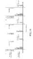
- FIG. 8 illustrates the positions of CSI-RSs that BSs transmit to a UE according to an embodiment of the present invention.
- the central control device 330 allocates resources 401, 402 and 403 to three CSI-RSs and transmits CSI-RSs in the allocated resources so that UE 2 for which CoMP transmission is supported can estimate channels from the three cells 300, 310 and 320 and channels carrying control information and system information. That is, reference numeral 401 denotes resources allocated to a CSI-RS used for channel estimation of Cell 1, reference numeral 402 denotes resources allocated to a CSI-RS used for channel estimation of Cell 2, and reference numeral 403 denotes resources allocated to a CSI-RS used for channel estimation of Cell 3.
- a set of resources allocated to at least one CSI-RS transmitted for channel estimation of a CoMP UE or a set of cells corresponding to the CSI-RS resources is called a measurement set.
- CSI feedback regarding the measurement set can be considered largely in two methods.
- One is to feedback CSI in a different CSI feedback mode at a different timing for each cell of the measurement set. For example, if the measurement set is ⁇ Cell-1, Cell-2, Cell-3 ⁇ , a feedback mode and timing are allocated to each cell in the per-cell CSI feedback method. That is, an allocation method described in Example 1 is used:
- Example 1 When feedback modes and timings are allocated to a CoMP UE on a cell basis as illustrated in Example 1, it is necessary to consider collision between feedback timings. In Example 1, collision can be avoided through an appropriate combination of a transmission period and an offset. However, a wrong setting of a transmission period and an offset, a carrier aggregation situation, or a Time Division Duplexing (TDD) situation can cause collision between feedback timings.
- a feedback is first transmitted to a cell having the highest priority in a collision. That is, information about a cell having a higher priority is fed back first, in case one of an RI, a PMI, and a CQI collides with another.
- This method is advantageous in that a feedback can be transmitted without considering CoMP even in the case of feedback collision between cells and thus a UE can receive data from at least one cell without performance degradation caused by multi-feedback collision.
- Cells are prioritized by signaling a measurement set and the priority levels of cells included in the measurement set to a UE by a BS and prioritizing the cells based on the priority levels of the cells by the UE.
- Cells can also be prioritized according to CSI-RS resource indexes for cells included in a measurement set or a higher priority level can be assigned to a cell with a shorter feedback period.
- the central control device 330 allocates additional resources for interference measurement to UE 2.
- the amount of data that UE 2 can receive per unit time is affected by the magnitude of interference as well as the strength of a signal. Accordingly, the central control device 330 allocates an Interference Measurement Resource (IMR) configured only for interference measurement to UE 2 so that UE 2 can accurately measure interference.
- IMR Interference Measurement Resource
- the BS allocates one IMR to a UE so that the UE measures the magnitude of common interference involved in the signal components of all CSI-RSs of a measurement set.
- the BS can also allocate a plurality of IMRs to a UE so that the UE measures interference in various situations.
- UE 2 measures signals received from the three cells 300, 310, and 320 using the allocated three CSI-RS resources 401, 402 and 403, and measures interference involved in the signals received from the three cells 300, 310 and 320 using an allocated IMR 410.
- the BS controls signal transmissions from neighboring cells using the IMR 410 so that much of interference with UE 2 is reflected in the IMR 410.
- an embodiment of the present invention considers the types of feedbacks to be transmitted to a BS, a method for generating and transmitting feedback information, and a UE feedback operation for the case in which different types of feedbacks collide at a specific timing.
- a BS allocates a plurality of feedbacks to the UE regarding signals and interference that can be generated.
- the UE then generates feedback information according to the allocated feedbacks and transmits the feedback information to the BS at a predetermined feedback transmission timing.
- the BS allocates one IMR to the UE, and the allocated IMR reflects interference from cells other than the cells of the measurement set, the BS and the UE operates as follows.
- the BS allocates FeedBacks (FBs) regarding four signals and interference as illustrated in Table 1 below and the UE generates and transmits feedback information according to the allocated FBs.
- Table 1 Signal component Interference Considerations FB 1 Cell-1 IMR + Cell-2 No blanking FB 2 Cell-1 IMR Blanking of Cell-2 FB 3 Cell-2 IMR + Cell-1 No blanking FB 4 Cell-2 IMR Blanking of Cell-1
- IMR + Cell-2 means that the UE considers the sum of interference measured in the IMR and interference measured in CSI-RS-2 received from Cell 2 as a feedback for FB 1. That is, FB 1 indicates a CSI feedback for the case in which a signal is received from Cell-1, and Cell-2 and cells reflected in the IMR other than the cells of the measurement set cause interference. FB 2 indicates a CSI feedback for the case in which a signal is received from Cell-1 and only cells other than the cells of the measurement set cause interference because Cell-2 is in blanking state and thus does not transmit a signal.
- the CSI of FB 1 and FB 2 include individual RIs, PMIs and CQIs or a common RI, a common PMI, and individual CQIs.
- FB 3 and FB 4 commonly indicate a CSI feedback for the case in which a signal is received from Cell-2, and FB 3 and FB 4 are for blanking of Cell-1 and non-blanking of Cell-1, respectively.
- FB 3 and FB 4 have individual RIs, individual PMIs, and individual CQIs or a common RI, a common PMI, and individual CQIs. That is, FBs are designed to have a common RI and a common PMI for the same signal component and separate CQIs for different interference situations.
- Timing 1 to Timing 4 are assigned as the transmission timings of the feedback information as illustrated in Table 2 below.
- the feedback information is prioritized in order to prevent collision between the transmission timings of different feedback information. As feedback information is prioritized, feedback information with a higher priority is transmitted despite the collision between the transmission timings of feedback information, while feedback information with a lower priority is be transmitted.
- Table 2 Signal component Interference Feedback timing Feedback priority FB 1 Cell-1 IMR + Cell-2 Timing 1 1 FB 2 Cell-1 IMR Timing 2 3 FB 3 Cell-2 IMR + Cell-1 Timing 3 2 FB 4 Cell-2 IMR Timing 4 4 4
- the feedback information is prioritized in various methods.
- One method of prioritizing feedbacks is for a BS to prioritize feedback information according to the priority index of the feedback information.
- the UE transmits a CSI feedback of FB 1 without transmitting a CSI feedback of FB 2.
- the BS transmits feedback priority indexes to the UE by RRC signaling as illustrated in the last column of Table 2 or FBs are prioritized in the order of FB allocation numbers without assigning additional priority indexes. That is, if FB 1 collides with FB 2, a feedback for FB 1 is transmitted with priority at a given timing, while a feedback for FB 2 is not transmitted. To generalize this operation, for indexes m and n (where m > n), a feedback is transmitted always for FB m, while a feedback is not transmitted for FB n, at a colliding transmission timing.
- Another method of prioritizing FBs is that feedback priorities are determined based on CSI-RS resource indexes corresponding to signal components for which feedback information is configured. That is, when a collision occurs between the transmission timings of two pieces of feedback information, the UE transmits feedback information with a lower CSI-RS resource index, while not transmitting feedback information with a higher CSI-RS resource index. For example, in Table 2, if the CSI-RS resource indexes for Cell-1 and Cell-2 are 1 and 2, respectively, feedback information for Cell-1 is transmitted with priority over feedback information for Cell-2.
- a third method for prioritizing feedback information is to determine the priority level of feedback information according to the type of interference involved in the feedback information.
- Feedback information for a case in which interference is measured only in an IMR has priority over feedback information for a case in which interference is measured in a plurality of resources such as "IMR + Cell-1", as illustrated in Table 2.
- IMR + Cell-1 resources such as "IMR + Cell-1”
- a case in which interference is measured in more resources has a higher feedback priority level than a case where interference is measured in fewer resources.
- the BS assigns priority indexes according to interference types and thus feedbacks are prioritized based on the assigned priority indexes.
- the BS assigns index 1 to a case where the UE measures interference only in an IMR and index 1 to a case where the UE considers both interference in the IMR and interference with Cell-1 in Table 2, the UE prioritizes feedbacks according to the interference indexes.
- Table 3 illustrates a situation in which a set of two IMRs ⁇ IMR 1, IMR 2 ⁇ and a plurality of related FBs are assigned to a UE.
- IMR 1 and IMR 2 represent interference measurement resources reflecting different interference situations.
- Another method of prioritizing feedbacks according to interference types is to give a higher priority level to feedback information with a lower IMR index than feedback information with a higher IMR index, when a BS assigns a plurality of IMRs to a UE as illustrated in Table 3.
- feedback information of FB 1 with a lower IMR index (e.g., IMR 1) is transmitted, while feedback information of FB 2 with a higher IMR index (e.g., IMR 2) is not transmitted, at a transmission timing at which FB 1 collides with FB 2 in Table 3.
- IMR 1 a lower IMR index
- IMR 2 with a higher IMR index e.g., IMR 2
- Table 3 Signal component Interference Feedback timing FB 1 Cell-1 IMR 1 Timing 1 FB 2 Cell-1 IMR 2 Timing 2 FB 3 Cell-2 IMR 1 Timing 3 FB 4 Cell-2 IMR 2 Timing 4
- a final method of prioritizing feedbacks uses the afore-described two feedback prioritizing methods (i.e. the CSI-RS resource index-based feedback prioritizing method and the method of prioritizing feedbacks according to interference types) in combination.
- the two feedback prioritizing methods i.e. the CSI-RS resource index-based feedback prioritizing method and the method of prioritizing feedbacks according to interference types
- feedback information with a lower CSI-RS resource index is transmitted with priority.
- the two feedbacks have the same CSI-RS resource index, they are prioritized based on interference types.
- the feedbacks are prioritized based on interference types involved in the feedbacks. However, if the two feedbacks have the same interference type, feedback information with a lower CSI-RS resource index is transmitted with priority.
- a BS first receives a feedback for a situation in which a UE receives data from a specific cell in various interference situations.
- a BS first receives a feedback for a situation where a UE receives data from different cells in the same interference situation.
- RI transmission has priority over wCQI or wCQI/PMI transmission, or wCQI or wCQI/PMI transmission has priority over sCQI transmission, at a transmission timing at which feedbacks with the same feedback priority levels collide.
- the above-described feedback prioritizing methods are used only at a transmission timing at which the same type of feedback information collides, in such a manner that a higher priority level is given to RI transmission than wCQI or wCQI/PMI transmission and a higher priority level is given to wCQI or wCQI/PMI transmission than sCQI transmission.
- Another method for transmitting CSI feedbacks regarding a measurement set assigned to a UE is to divide the measurement set into one or more subsets and setting a CSI feedback mode and timing for each subset, for CSI feedback.
- a method for transmitting a CSI feedback on a subset basis a UE-Preferred cell Index (PI) is included on a subset basis and only a feedback for a cell corresponding to the PI is transmitted.
- PI-including feedback methods according to Embodiments 2, 3 and 4 will be described below in conjunction with DS, DS/DB, and JT.
- Another embodiment of the present invention provides a method for transmitting feedbacks in allocated feedback modes at allocated timings at a CoMP UE in a cellular mobile communication system using DS.
- a BS indicates a measurement set and a plurality of subsets of the measurement set to a UE and allocates a feedback mode and timing for each subset to the UE. For instance, assuming that the measurement set is ⁇ Cell-1, Cell-2, Cell-3, Cell-4 ⁇ and the BS wants to receive CSI for UE-preferred two cells among the cells of the allocated measurement set, the BS allocates two feedback modes and timings to the UE and indicates a subset corresponding to the respective feedback modes and timings to the UE. In the example, the following two feedback modes and timings and the subsets corresponding to the feedback modes and timings are set:
- Mode A indicates that feedback information transmitted from a UE includes a PI in addition to conventionally included RI, PMI, and CQI information.
- M PI and N OFFSET,PI are parameters representing the feedback period and offset of the PI, respectively, which can be defined as
- Another method for defining the feedback timing of a PI is to set the period of the PI to a multiple of a wCQI period independently of the timing of an RI and apply an additional offset. That is, the period and offset of the PI are defined as
- the period and offset of the PI are set to N pd ⁇ M PI and N OFFSET,CQI +N OFFSET,PI , respectively in Example 2.
- the period and offset of the PI are set to N pd ⁇ H ⁇ M PI and N OFFSET,CQI +N OFFSET,PI , respectively.
- a CQI/PMI is transmitted shortly after the PI, a CQI/PMI related to the latest RI and PI or a CQI/PMI set assuming a fixed RI is fed back.
- the fixed RI is for rank 1, which offers the benefit of ensuring a normal operation when an available RI is different for each cell. That is, if a first cell supports up to rank 4 and a second cell merely supports rank 2, an RI feedback for the first cell is not applied to the second cell.
- the smaller value between a rank for the latest RI feedback and a maximum rank available in a cell related to a new PI is another assumption for an RI in generating a CQI/PMI, when the CQI/PMI, not the RI, is transmitted shortly after a PI.
- the maximum available rank in the cell related to the new PI is based on a CSI-RS antenna port setting or is a maximum rank freely set by the BS.
- a UE feeds back different information according to the number of CSI-RS antenna ports in the cell indicated by a PI. For example, if Cell-1 has 8 antenna ports, each of the other cells has 4 or fewer antenna ports, and a PI indicates Cell-1, feedback information includes two types of PMIs or PTIs in addition to an RI and a CQI corresponding to the 8 antennas. However, if the PI indicates Cell-2, the feedback information has to only include an RI, a CQI, and one type of PMI. The PI occupies 1 or more bits. Table 4 illustrates an example of the indexes of cells indicated by a 2-bit PI. Table 4 PI field Cell index 00 1 10 2 11 3 01 4
- a measurement set is ⁇ Cell-1, Cell-2, Cell-3, Cell-4 ⁇ and the BS wants to get information about one preferred cell between Cell-1 and Cell-2 and information about one preferred cell between Cell-3 and Cell-4, the BS allocates feedbacks as follows:
- a PI has an independent feedback timing and is jointly encoded with an RI for transmission in Example 3.
- a set of cells corresponding to each feedback is transmitted together with feedback allocations to a UE, independently of a measurement set or is transmitted to the UE as bitmap information of the measurement set.
- the BS transmits a bitmap sequence [1, 1, 0, 0] regarding the measurement set in feedback allocation 1 and a bitmap sequence [0, 0, 1, 1] regarding the measurement set in feedback allocation 2.
- FIG. 9 illustrates feedback transmission timings and feedback information of a UE regarding two feedback allocations in Example 3 and Example 4.
- Example 3 and Example 4 are extensions of the conventional Mode 1-1 for 4 or fewer CSI-RS antenna ports.
- the BS When Mode 2-1 is extended, the BS additionally transmits K to the UE.
- the period of a PI is also set to an M PI multiple of an RI period and the offset of the PI is set to the sum of an RI offset and N OFFSET,PI .
- the PI is jointly encoded with the RI without additionally defining a PI timing.
- the period and offset of the PI is set to an M PI multiple of a WCI period and the sum of a wCQI offset and N OFFSET,PI , respectively.
- a UE feeds back a PI additionally in the conventional feedback structure as in Example 2 and Example 3.
- the BS allocates feedbacks as follows:
- Example 4 since a cell set includes a single element in feedback allocation 1, there is no need to define a PI period. When a cell set includes only one element in a feedback allocation, a PI period is not defined, or even though a PI period is defined, a PI is not fed back.
- a collision occurs between the transmission timings of the channel information.
- a feedback for a feedback allocation having a higher priority is always transmitted first. That is, when one of an RI, a PMI, and a CQI collides with another, information for a higher-priority feedback allocation is first fed back.
- This method enables a UE to receive data from at least one cell without performance degradation caused by multi-feedback collision, despite collision between cells.
- Cells are prioritized by signaling priority information together with feedback allocations to a UE by a BS and determining feedback priority levels according to the priority information by the UE. Or, the priority levels of cells are determined based on the indexes of feedback allocations. Or, a higher priority level is assigned to a feedback allocation having the shortest feedback period.
- a subsequent RI, PMI and CQI is fed back based on a preset PI value.
- the PI value is indicated to the UE by higher-layer signaling or is determined to be a feedback for a cell having the smallest index in a cell set in a feedback allocation.
- a PMI and a CQI are calculated on the same assumption as non-PI transmission. Consequently, the feedback prioritization methods according to the first embodiment of the present invention are performed in a similar manner in the second embodiment of the present invention.
- a third embodiment of the present invention provides a method for transmitting a feedback in an allocated feedback mode at an allocated timing at a CoMP UE in a cellular mobile communication system using DS/DB.
- a UE feeds back to a BS both channel information in case of Interference Cell (I-cell) off and channel information in case of I-cell on. These two feedbacks are performed independently.
- I-cell Interference Cell
- PMI representing spatial information between the UE and a specific cell do not change much in both cases
- the RI and PMI are set to the same values in both cases and different CQI values are set in both cases.
- an RI and PMI for the case of I-cell off are set to the RI and PMI of the primary feedback (i.e. the reference feedback).
- the UE calculates a CQI for the case of I-cell off based on at least one of the set RI and PMI, thus setting the CQI separately from a CQI for the case of I-cell on.
- channel information for the I-cell off case may includes only the CQI.
- a UE acquires channel information in the case of I-cell off and in the case of I-cell on in two methods.
- One of the channel information acquisition methods is that a BS notifies a UE of the index of an I-cell along with a measurement set. For example, if the BS indicates ⁇ Cell-1, Cell-2, Cell-3 ⁇ as the measurement set and Cell-1 as an I-cell, the UE has only to feed back channel information only for an I-cell off case regarding Cell-1. Moreover, the UE should feed back channel information for Cell-1 off and Cell-1 in cases regarding Cell-2 and Cell-3. Regarding Cell-2 and Cell-3, a common RI and PMI and two different CQIs are fed back for both Cell-1 on and Cell-1 off cases.
- a CQI for the I-cell on case be called a DS-CQI and a CQI for the I-cell off case be called a DB-CQI.
- the DS-CQI and the DB-CQI are fed back at the same or different timings.
- the DB-CQI is fed back as a separate value or a delta DB-CQI being the difference from the DS-CQI is fed back. If the RI is 1, a CQI for one codeword is fed back. Then, the delta DB-CQI is defined simply as (DB-CQI - DS-CQI).
- a CQI for the second codeword is fed back as the difference from the CQI for the first CQI. That is, when DS-CQIs for the first and second codewords are respectively called DS-CQI_CW1 and DS-CQI_CW2, the DS-CQI_CW1 and a delta_DS-CQI_CW2 are fed back conventionally.
- delta_DS-CQI_CW2 DS-CQI_CW2 - DS-CQI_CW1.
- DB-CQI_CW1 and DB-CQI_CW2 are DB-CQI_CW1 and DB-CQI_CW2, respectively.
- delta_DB-CQI_CW1 and delta_DB-CQI_CW2 are fed back respectively and used as follows.
- a BS notifies a UE of a measurement set and a plurality of subsets of the measurement set and allocates a feedback mode and timing for each subset to the UE in the third embodiment of the present invention.
- the third embodiment of the present invention differs from the second embodiment of the present invention in that a DB-CQI or delta_DB-CQI is included in each feedback.
- the BS wishes to receive channel information about two UE-preferred cells selected from the measurement set and to receive a delta_DB-CQI and a DS-CQI at the same timing, the BS allocates two feedback modes and timings to the UE and indicates a subset of the measurement set corresponding to the feedback modes and timings to the UE.
- the two feedback modes and timings and the subset are set as follows.
- Mode B indicates that feedback information to be transmitted from the UE includes a delta_DB-CQI in addition to a conventionally transmitted RI, PMI, and CQI, and a PI.
- the delta_DB-CQI is jointly encoded with a DS-CQI and fed back at the same timing. That is, the transmission period and offset of the DS-CQI and the delta_DB-CQI are set to N pd and N OFFSET,PI , respectively. If the PI indicates an I-cell, a DB-CQI is not needed. Therefore, the delta_DB-CQI is set to 0 or not transmitted, while only the DS-CQI is transmitted.
- Example 5 is an extension of the conventional Mode 1-1.
- the BS will additionally transmit K to the UE.
- the period of a PI is set to an M PI multiple of an RI period and the offset of the PI is set to the sum of an RI offset and N OFFSET,PI .
- the PI is jointly encoded with the RI and transmitted together without defining an additional PI timing.
- the period and offset of a PI for a wCQI are defined, respectively, as an M PI multiple of the period of the wCQI and the sum of the offset of the wCQI and N OFFSET,PI .
- a delta_DB-CQI is defined for each of a wCQI and an sCQI and transmitted together with a DS-CQI, or a delta_DB-CQI is defined for one of the wCQI and the sCQI and transmitted together with a DS-CQI at a given timing.
- the UE In a feedback mode for 8 CSI-RS antenna ports, which additionally includes two types of PMIs and two types of PTIs, the UE additionally feeds back a PI and a delta_DB-CQI in the conventional feedback structure in the same manner as in Example 5.
- the BS configures two feedback modes, timing information about the transmission timing of the DB-CQI, and a subset of the measurement set corresponding to the feedback modes and timing, as follows.
- Mode C includes a parameter H" indicating the period of a DB-CQI, compared to Mode B of Example 5.
- the transmission period and offset of the DB-CQI are set to H" ⁇ N pd and N OFFSET,CQI , respectively. That is, in the situation in which the DS-CQI is transmitted in a period of N pd , a DB-CQI is transmitted every H" times. Instead of the DB-CQI, a delta_DB-CQI is transmitted.
- Example 6 when the PI indicates an I-cell, the DB-CQI is not needed and thus only the DS-CQI is transmitted.
- Example 11 illustrates feedback transmission timings and feedback information of a UE in two feedback allocations, when a PI indicates an I-cell in feedback allocation 1 and the PI indicates a cell other than the I-cell in feedback allocation 2.
- Example 6 is an extension of the conventional Mode 1-1.
- the BS additionally transmits K to the UE.
- the period of a PI is set to an M PI multiple of an RI period and the offset of the PI is set to the sum of an RI offset and No FFSET,PI .
- the PI is jointly encoded with the RI and transmitted together without defining an additional PI timing.
- the period and offset of a PI for a wCQI are defined respectively as an M PI multiple of the period of the wCQI and the sum of the offset of the wCQI and N OFFSET,PI .
- a DB-CQI is defined for each of a wCQI and an sCQI and transmitted together with a DS-CQI, or a DB-CQI is defined for one of the wCQI and the sCQI and transmitted together with a DS-CQI at a given timing.
- the transmission timing of a DB-sCQI i.e.
- a DB-CQI for an sCQI is set such that (H-1) DB-sCQIs are transmitted at an interval of N pd subframes after a timing of the transmission period of a DB-wCQI, i.e. a DB-CQI for a wCQI, H" ⁇ N pd and the offset N OFFSET,CQI .
- Example 7 is an example of available feedback allocations, when a DB-CQI is transmitted by extending Mode 2-1.
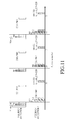
- FIG. 12 illustrates feedback transmission timings and feedback information of a UE in two feedback allocations, when a PI indicates an I-cell in feedback allocation 1 and the PI indicates a cell other than the I-cell in feedback allocation 2.
- Mode D is a new feedback mode that is an extension of the conventional Mode 2-1 requiring additional transmission of a DB-CQI.
- a feedback mode for 8 CSI-RS antenna ports including two types of PMIs and two types of PTIs additionally, a UE feeds back a PI and a DB-CQI additionally in the conventional feedback structure in the same manner as in Example 7.
- a BS indicates an IMR for each cell as well as a measurement set to the UE. That is, when the BS signals CSI-RS resources for signal measurement, an IMR for an I-cell on case, and an IMR for an I-cell off case regarding each cell of the measurement set to the UE, the UE acquires both a DB-CQI and a DS-CQI for the cell based on channel information acquired from the resources. For a cell in which only one IMR is known, the UE only has to calculate a DS-CQI.
- the BS allocates ⁇ Cell-1, Cell-2, Cell-3 ⁇ as the measurement set and indicates to the UE one IMR for Cell-1 and two IMRs for each of Cell-2 and Cell-3
- the UE feeds back one piece of channel information for Cell-1 and channel information for two cases for each of Cell-2 and Cell-3.
- the RI and PMI included in the channel information about two IMRs for each of Cell-2 and Cell-3 are set to the same values. Different CQIs are generated for the two cases based on at least one of the set RI and PMI.
- the DS-CQI and the DB-CQI are fed back to the BS in a specific feedback mode at a specific timing.
- the feedback mode and timing are set in the methods described in Example 5, Example 6, and Example 7.
- the UE classifies two pieces of channel information generated for each of Cell-2 and Cell-3 into primary CSI and secondary CSI. For instance, the UE sets channel information including the smaller between two CQIs as primary CSI and the other channel information as secondary CSI.
- the RI and PMI included in the secondary CSI are set to the same values as the RI and PMI included in the primary CSI, and a CQI for the secondary CSI is calculated to be feedback based on at least one of the set RI and PMI. Since the RI and PMI of the secondary CSI are set based on the RI and PMI of the primary CSI, the primary CSI is used as a reference CSI for the secondary CSI.
- a fourth embodiment of the present invention provides a method for transmitting a feedback in an allocated feedback mode at an allocated timing at a CoMP UE in a cellular mobile communication system using JT.
- a UE needs to feed back channel information in the case of simultaneous transmission from some cells of a measurement set as well as channel information for each cell of the measurement set to a BS.
- a BS Aside from channel information for each cell, an RI, PMI, wCQI, and sCQI according to cooperation between cells are referred to as a JT_RI, JT_PMI, JT_wCQI, and JT_sCQI, respectively.
- the UE feeds back all or a part of the cooperation information to the BS.
- the JT_RI is not included in the feedback information because the BS can estimate the JT_RI based on the channel information for each cell.
- the JT_PMI is configured to include only phase difference information between cells that consider cooperation, rather than being configured to be a PMI for JT. If the JT_wCQI and the JT_sCQI are generically called a JT_CQI, this value is a CQI needed for a cooperation situation or a CQI difference between a cooperation case and a non-cooperation case.
- the JT_CQI is defined as a CQI difference, it is defined commonly or separately for two codewords, like a delta_DB-CQI defined in the third embodiment of the present invention.
- channel information for coordinated transmission is encoded and transmitted jointly with individual feedbacks for cells of a measurement set at the same timing, or is fed back in a different feedback mode at a different timing from the individual feedbacks for the cells.
- the case of transmitting information for coordinated transmission together with individual feedbacks for the cells of a measurement set will be described. Both or either of the JT_CQI and JT_PMI are transmitted while the JT_RL is not transmitted.
- the BS when a JT feedback is transmitted at the same timing as a DS-CQI for an individual cell, the BS indicates a measurement set and a plurality of subsets of the measurement set to the UE and allocates a feedback mode and timing to each subset as in the third embodiment of the present invention.
- the difference between the fourth embodiment and the third embodiment of the present invention is that a DB-CQI is replaced with a JT-CQI/JT-PMI in each feedback.
- the BS allocates two feedback modes and timings to the UE and indicates a subset of the measurement set corresponding to the feedback modes and timings to the UE.
- the two feedback modes and timings and the subset are set as follows:
- Mode A is identical to Mode A defined in Example 2, meaning that the UE needs to feedback a conventionally transmitted RI, PMI and CQI and a PI.
- Mode E is a mode indicating additional transmission of a JT feedback in Mode A.
- the UE feeds back a JT feedback based on cooperation between a cell corresponding to a PI selected in the indicated feedback allocation 1 and a cell to be selected in feedback allocation 2 to the BS at a CQI transmission timing.
- Mode E is indicated as the feedback mode
- the index of a feedback allocation for which cooperation is indicated to the UE and the feedback allocation index is directly signaled to the UE by the BS through higher-layer signaling or is preset to feedback allocation 1.
- the JT_CQI/JT-PMI is then fed back with a DS-CQI in a transmission period of N pd with an offset of N OFFSET,CQI .
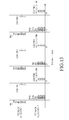
- FIG. 13 illustrates feedback transmission timings and feedback information of a UE in two feedback allocations regarding Example 8.
- Example 8 is an extension of the conventional Mode 1-1.
- the BS additionally transmits K to the UE.
- the period of a PI is set to an M PI multiple of an RI period and the offset of the PI is set to the sum of an RI offset and N OFFSET,PI .
- the PI is jointly encoded with the RI and transmitted together without defining an additional PI timing.
- the period and offset of a PI for a wCQI are defined respectively as an M PI multiple of the period of the wCQI and the sum of the offset of the wCQI and N OFFSET,PI , respectively.
- both a JT_wCQI and a JT_sCQI are defined and transmitted together with a DS-CQI, or one of the JT_wCQI and the JT_sCQI is defined and transmitted together with a DS-CQI at a given timing.
- the UE In a feedback mode for 8 CSI-RS antenna ports, which additionally includes two types of PMIs and two types of PTIs, the UE additionally feeds back a PI and a JT_CQI/JT_PMI in the conventional feedback structure in the same manner as in Example 8.
- the BS configures two feedback modes, timing information about the transmission timing of the JT_CQI/JT_PMI, and a subset of the measurement set corresponding to the feedback modes and timing, as follows.
- Mode F includes a parameter H" indicating the period of a JT_CQI/JT_PMI, compared to Mode E in Example 8.
- the transmission period and offset of the JT_CQI/JT_PMI are set to H" ⁇ N pd and N OFFSET,CQI , respectively. That is, in a situation in which a DS-CQI is transmitted in a period of N pd , a JT_CQI/JT_PMI is transmitted every H" times.
- FIG. 14 illustrates feedback transmission timings and feedback information of a UE in two feedback allocations, with respect to Example 9.
- Example 9 is an extension of the conventional Mode 1-1. When Mode 2-1 is extended, the BS additionally transmits K to the UE.
- the period of a PI is set to an M PI multiple of an RI period and the offset of the PI is set to the sum of an RI offset and N OFFSET,PI .
- the PI is jointly encoded with the RI and transmitted together without defining an additional PI timing.
- the period and offset of a PI for a wCQI are defined respectively as an M PI multiple of the period of the wCQI and the sum of the offset of the wCQI and N OFFSET,PI .
- both a JT_wCQI and a JT_sCQI are defined and transmitted together with a DS-CQI, or only one of the JT_wCQI and the JT_sCQI is defined and transmitted together with a DS-CQI at a given timing.
- the transmission timing of the JT_sCQI is set such that (H-1) DB-sCQIs are transmitted at an interval of N pd subframes after a timing of the transmission period of a JT_wCQI, H" ⁇ N pd and its offset N OFFSET,CQI .
- the UE In a feedback mode for 8 CSI-RS antenna ports, which additionally includes two types of PMIs and two types of PTIs, the UE additionally feeds back a JT_CQI/JT_PMI in the conventional feedback structure in the same manner as in Example 9.
- Channel information for coordinated transmission is fed back in a different mode at a different timing from an individual feedback for each cell.
- the measurement set is ⁇ Cell-1, Cell-2, Cell-3, Cell-4 ⁇ and the BS wants to receive channel information about two UE-preferred cells selected from the measurement set, to receive a JT feedback based on cooperation between the cells, and to receive the JT feedback separately from channel information for each cell
- the BS configures two feedback modes for individual cell feedbacks, and one feedback mode for JT, as follows.
- Mode G is a mode in which a JT_RI, JT_PMI and JT_CQI are transmitted as feedback information based on JT between cells selected from feedback allocation 1 and feedback allocation 2.
- JT feedback feedback periods and offsets are set as in the conventional Mode 1-1 and a feedback allocation number for JT is also set. The feedback allocation number is signaled separately to the UE. Or the feedback allocation number is for cooperation between predetermined feedback allocation numbers or between predetermined cells.
- a JT_RI is not fed back and only a JT_PMI and a JT_CQI are transmitted. Thus, M RI and N OFFSET,RI are not set.
- FIG. 15 is a block diagram illustrating a UE according to an embodiment of the present invention.
- the UE includes a communication module 710 and a controller 720.
- the communication module 710 transmits or receives data externally.
- the communication module 710 transmits channel information for CoMP to a central control device under the control of the controller 720.
- the controller 720 controls the states and operations of all components in the UE.
- the controller 720 selects feedback information for the best cell or coordinated communication according to the communication states between the UE and cells and feed back channel information about the selected cell to the central control device.
- the controller 720 includes a channel estimator 730.
- the channel estimator 730 determines feedback information on a CSI-RS basis according to CoMP set information and feedback mode information received from the central control device and estimates channels using received CSI-RSs.
- the channel estimator 730 feeds back CoMP-related channel information to the central control device by controlling the communication module 710.
- the UE is not limited to the specific configuration. That is, the UE further includes many other components according to its functions.
- the UE additionally includes a display for displaying the current state of the UE, an input unit for receiving a signal such as a function execution command from a user, a memory for storing data generated from the UE, etc.
- FIG. 16 is a flowchart illustrating an operation of the UE according to an embodiment of the present invention.
- the UE receives CoMP set information and feedback mode information from the central control device in step 801 and determines necessary feedbacks on a CSI-RS basis based on the received information in step 802.
- the UE estimates channels using CSI-RSs based on the determined feedbacks.
- the UE then feeds back CoMP-related channel information to the central control device according to the channel estimation result in step 804.
- FIG. 17 is a block diagram of a central control device according to an embodiment of the present invention.
- the central control device includes a controller 910 and a communication module 920.
- the controller 910 controls the states and operations of all components in the central control device.
- the controller 910 allocates CSI-RSs to resources on a cell basis, for channel estimation at the UE, allocates a CoMP set when needed, and transmits CoMP set information to the UE.
- the controller 910 further includes a per-cell resource allocator 930.
- the per-cell resource allocator 930 allocates resources to CSI-RSs for channel estimation at the UE on a cell basis and transmits CSI-RSs in the allocated resources through the communication module 920. Resources for each cell are allocated in correspondence with CSI-RSs for channel estimation.
- the communication module 920 transmits and receives data to and from the UE or a managed cell.
- the communication module 920 transmits CSI-RSs to the UE in the allocated resources and receives feedback information under the control of the controller 910.
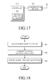
- FIG. 18 is a flowchart illustrating an operation of the central control device according to an embodiment of the present invention.
- the central control device allocates resources to CSI-RSs for channel estimation of a UE on a cell basis in step 1001, and transmits CSI-RSs in the resources to the UE in step 1002.
- the central control device receives feedback information including channel information from the UE.
- an effective feedback can be performed by setting the types, periods, and timings of feedback information, taking into account multi-CSI feedbacks in an LTE-A CoMP system where a plurality of BSs supports coordinated downlink transmission to a UE.
Priority Applications (1)
| Application Number | Priority Date | Filing Date | Title |
|---|---|---|---|
| EP20211166.2A EP3800824A1 (fr) | 2011-10-12 | 2012-10-12 | Appareil et procédé de transmission et réception d'informations rétroactives dans un système de communications mobile |
Applications Claiming Priority (6)
| Application Number | Priority Date | Filing Date | Title |
|---|---|---|---|
| US201161546294P | 2011-10-12 | 2011-10-12 | |
| US201161547294P | 2011-10-14 | 2011-10-14 | |
| KR20110113894 | 2011-11-03 | ||
| KR20110117483 | 2011-11-11 | ||
| KR1020120008868A KR20130039644A (ko) | 2011-10-12 | 2012-01-30 | 통신 시스템에서의 피드백 송수신 방법 및 장치 |
| US201261636989P | 2012-04-23 | 2012-04-23 |
Related Child Applications (2)
| Application Number | Title | Priority Date | Filing Date |
|---|---|---|---|
| EP20211166.2A Division-Into EP3800824A1 (fr) | 2011-10-12 | 2012-10-12 | Appareil et procédé de transmission et réception d'informations rétroactives dans un système de communications mobile |
| EP20211166.2A Division EP3800824A1 (fr) | 2011-10-12 | 2012-10-12 | Appareil et procédé de transmission et réception d'informations rétroactives dans un système de communications mobile |
Publications (3)
| Publication Number | Publication Date |
|---|---|
| EP2582084A2 true EP2582084A2 (fr) | 2013-04-17 |
| EP2582084A3 EP2582084A3 (fr) | 2013-09-18 |
| EP2582084B1 EP2582084B1 (fr) | 2021-01-20 |
Family
ID=47074649
Family Applications (2)
| Application Number | Title | Priority Date | Filing Date |
|---|---|---|---|
| EP20211166.2A Pending EP3800824A1 (fr) | 2011-10-12 | 2012-10-12 | Appareil et procédé de transmission et réception d'informations rétroactives dans un système de communications mobile |
| EP12188379.7A Active EP2582084B1 (fr) | 2011-10-12 | 2012-10-12 | Appareil et procédé de transmission et réception d'informations rétroactives dans un système de communications mobile |
Family Applications Before (1)
| Application Number | Title | Priority Date | Filing Date |
|---|---|---|---|
| EP20211166.2A Pending EP3800824A1 (fr) | 2011-10-12 | 2012-10-12 | Appareil et procédé de transmission et réception d'informations rétroactives dans un système de communications mobile |
Country Status (3)
| Country | Link |
|---|---|
| US (8) | US9002345B2 (fr) |
| EP (2) | EP3800824A1 (fr) |
| WO (1) | WO2013055152A1 (fr) |
Cited By (6)
| Publication number | Priority date | Publication date | Assignee | Title |
|---|---|---|---|---|
| WO2015113249A1 (fr) * | 2014-01-29 | 2015-08-06 | 华为技术有限公司 | Procédé, appareil et système pour une communication coordonnée |
| CN107005299A (zh) * | 2014-10-10 | 2017-08-01 | 瑞典爱立信有限公司 | 用于csi反馈的方法 |
| EP3280207A1 (fr) * | 2011-10-31 | 2018-02-07 | Samsung Electronics Co., Ltd. | Procédé de rétroaction, équipement utilisateur et équipement réseau pour communication multipoint collaborative dans un système de communication |
| CN109803418A (zh) * | 2017-11-17 | 2019-05-24 | 华为技术有限公司 | 一种通信方法及装置 |
| EP3800824A1 (fr) | 2011-10-12 | 2021-04-07 | Samsung Electronics Co., Ltd. | Appareil et procédé de transmission et réception d'informations rétroactives dans un système de communications mobile |
| EP3917247A1 (fr) * | 2017-01-06 | 2021-12-01 | Huawei Technologies Co., Ltd. | Procédé de transmission d'informations, dispositif terminal et dispositif de réseau d'accès |
Families Citing this family (33)
| Publication number | Priority date | Publication date | Assignee | Title |
|---|---|---|---|---|
| JP5776551B2 (ja) * | 2009-09-18 | 2015-09-09 | ソニー株式会社 | 中継局、中継方法、及び無線通信装置 |
| US8797966B2 (en) | 2011-09-23 | 2014-08-05 | Ofinno Technologies, Llc | Channel state information transmission |
| EP2774417A4 (fr) * | 2011-11-04 | 2015-07-22 | Intel Corp | Rétroaction d'informations d'état de canal dans un système multipoint coordonné |
| US8885569B2 (en) | 2011-12-19 | 2014-11-11 | Ofinno Technologies, Llc | Beamforming signaling in a wireless network |
| US9008585B2 (en) | 2012-01-30 | 2015-04-14 | Futurewei Technologies, Inc. | System and method for wireless communications measurements and CSI feedback |
| US9723506B2 (en) * | 2012-04-13 | 2017-08-01 | Lg Electronics Inc. | Method and apparatus for reporting channel state information in wireless communication system |
| US9204317B2 (en) * | 2012-05-11 | 2015-12-01 | Telefonaktiebolaget L M Ericsson (Publ) | Methods and arrangements for CSI reporting |
| EP2850750B1 (fr) * | 2012-05-16 | 2016-10-12 | Telefonaktiebolaget LM Ericsson (publ) | Procédé et agencement dans un système de communication sans fil |
| US9560540B2 (en) | 2012-05-16 | 2017-01-31 | Telefonaktiebolaget Lm Ericsson (Publ) | Method and arrangement in a wireless communication system |
| CN103490865B (zh) * | 2012-06-11 | 2017-09-01 | 电信科学技术研究院 | 一种多点协作传输的反馈方法、装置及系统 |
| WO2014035136A1 (fr) * | 2012-08-28 | 2014-03-06 | 엘지전자 주식회사 | Procédé de fourniture de rétroaction d'informations d'état de canal dans un système de communication sans fil et appareil pour ce procédé |
| US8923880B2 (en) | 2012-09-28 | 2014-12-30 | Intel Corporation | Selective joinder of user equipment with wireless cell |
| CN103795491B (zh) * | 2012-11-01 | 2019-01-15 | 中兴通讯股份有限公司 | 信道状态信息的处理方法、基站和终端 |
| EP2941917A4 (fr) * | 2013-01-03 | 2016-09-07 | Intel Corp | Héritage d'indicateur de rang de rapport restreint d'informations d'état de canal de secteur de trame |
| KR20140125926A (ko) * | 2013-04-19 | 2014-10-30 | 삼성전자주식회사 | 협력 통신을 위한 기지국 간 정보 교환 방법 및 장치 |
| WO2014172863A1 (fr) * | 2013-04-25 | 2014-10-30 | 华为技术有限公司 | Procede de suppression de brouillage, dispositif associe et systeme |
| CN104219022B (zh) * | 2013-05-31 | 2019-01-15 | 中兴通讯股份有限公司 | 一种虚拟多天线系统的信令传输方法、装置及系统 |
| KR102122814B1 (ko) | 2013-07-10 | 2020-06-16 | 삼성전자 주식회사 | 이동 통신 시스템에서 다중 사용자 간섭 측정 방법 및 장치 |
| CN104348592B (zh) * | 2013-08-02 | 2019-03-15 | 夏普株式会社 | 配置csi过程的方法和基站以及csi反馈方法和用户设备 |
| WO2015042870A1 (fr) | 2013-09-27 | 2015-04-02 | Qualcomm Incorporated | Création de rapport de csi pour fonction eimta lte-tdd |
| US10009128B2 (en) * | 2014-03-05 | 2018-06-26 | Lg Electronics Inc. | Method for reporting channel state reflecting interference cancellation performance and apparatus for same |
| US10128927B2 (en) * | 2014-05-19 | 2018-11-13 | Panasonic Intellectual Property Corporation Of America | Channel state information reporting enhancement for network assisted interference cancellation and suppression |
| US10404348B2 (en) * | 2015-04-08 | 2019-09-03 | Lg Electronics Inc. | Method for reporting channel state and apparatus therefor |
| CN106301509B (zh) * | 2015-05-21 | 2020-01-17 | 电信科学技术研究院 | 一种信道状态信息反馈方法和终端 |
| US10230441B2 (en) | 2016-02-12 | 2019-03-12 | Samsung Electronics Co., Ltd. | Method and apparatus for channel status information feedback in mobile communication system |
| CN107294583B (zh) * | 2016-03-31 | 2020-10-16 | 华为技术有限公司 | 一种信道状态测量方法、装置及存储介质 |
| US10314037B2 (en) | 2016-07-08 | 2019-06-04 | Qualcomm Incorporated | Latency reduction techniques in wireless communications |
| WO2018027908A1 (fr) * | 2016-08-12 | 2018-02-15 | Qualcomm Incorporated | Transmission dynamique à faisceaux multiples destinée à une nouvelle technologie radio à entrées et à sorties multiples |
| US9979456B1 (en) | 2017-01-27 | 2018-05-22 | At&T Intellectual Property I, L.P. | Facilitating an enhanced resources indicator for channel state reporting in a wireless communication system |
| WO2019028867A1 (fr) * | 2017-08-11 | 2019-02-14 | 富士通株式会社 | Procédé et appareil de configuration de mesure d'interférence, procédé et appareil de mesure d'interférence, et système de communication |
| JP6714151B2 (ja) * | 2017-09-08 | 2020-06-24 | エルジー エレクトロニクス インコーポレイティド | 無線通信システムにおけるチャネル状態情報を報告するための方法及びそのための装置 |
| US11646851B2 (en) * | 2019-09-19 | 2023-05-09 | Qualcomm Incorporated | Channel state information reporting prioritization |
| CN116941203A (zh) * | 2021-02-18 | 2023-10-24 | 苹果公司 | 用于稳健的csi反馈的系统和方法 |
Family Cites Families (30)
| Publication number | Priority date | Publication date | Assignee | Title |
|---|---|---|---|---|
| FR359785A (fr) | 1905-05-22 | 1906-04-04 | Dresdner Gasmotorenfabrik Vorm | Appareil de rappel pour l'allumage électromagnétique dans les moteurs à explosions |
| JP4976914B2 (ja) | 2007-05-01 | 2012-07-18 | 株式会社エヌ・ティ・ティ・ドコモ | 基地局装置及び通信制御方法 |
| WO2009120048A2 (fr) | 2008-03-28 | 2009-10-01 | Lg Electronics Inc. | Procédé permettant d’éviter les interférences intercellulaires dans un environnement multicellulaire |
| US8385452B2 (en) | 2008-10-24 | 2013-02-26 | Qualcomm Incorporated | Method and apparatus for separable channel state feedback in a wireless communication system |
| US8159978B2 (en) * | 2009-02-05 | 2012-04-17 | Lg Electronics Inc. | Method and apparatus of transmitting feedback message in wireless communication system |
| EP2409438B1 (fr) * | 2009-03-17 | 2021-10-13 | Nokia Solutions and Networks Oy | Configuration de la transmission d'informations de rétroaction périodique sur un canal partagé de liaison montante physique (pusch) |
| CN101873601A (zh) | 2009-04-27 | 2010-10-27 | 松下电器产业株式会社 | 在无线通信系统中设置参考信号的方法以及系统 |
| EP2416619B1 (fr) | 2009-04-30 | 2015-01-21 | Huawei Technologies Co., Ltd. | Procédé permettant de rapporter des informations d'état de canal, procédé d'estimation de canal, terminal et station de base |
| KR101568291B1 (ko) | 2009-07-10 | 2015-11-20 | 삼성전자주식회사 | 단말기 및 기지국, 및 단말기의 동작방법 |
| WO2011071291A2 (fr) * | 2009-12-07 | 2011-06-16 | 엘지전자 주식회사 | Procédé de transmission d'un signal de référence de sondage dans un système de communication comp en liaison montante, et appareil correspondant |
| US8824384B2 (en) | 2009-12-14 | 2014-09-02 | Samsung Electronics Co., Ltd. | Systems and methods for transmitting channel quality information in wireless communication systems |
| CN102812658B (zh) * | 2010-01-08 | 2015-12-16 | 交互数字专利控股公司 | 针对多个载波的信道状态信息传输的方法及设备 |
| US8599708B2 (en) | 2010-01-14 | 2013-12-03 | Qualcomm Incorporated | Channel feedback based on reference signal |
| US8848520B2 (en) * | 2010-02-10 | 2014-09-30 | Qualcomm Incorporated | Aperiodic sounding reference signal transmission method and apparatus |
| WO2011115421A2 (fr) | 2010-03-17 | 2011-09-22 | Lg Electronics Inc. | Procédé et appareil permettant d'obtenir des informations de configuration de signal de référence d'informations d'état de canal (csi-rs) dans un système de communication sans fil supportant de multiples antennes |
| KR101253197B1 (ko) * | 2010-03-26 | 2013-04-10 | 엘지전자 주식회사 | 참조신호 수신 방법 및 사용자기기, 참조신호 전송 방법 및 기지국 |
| US8886250B2 (en) * | 2010-06-18 | 2014-11-11 | Qualcomm Incorporated | Channel quality reporting for different types of subframes |
| US9136997B2 (en) | 2010-05-04 | 2015-09-15 | Qualcomm Incorporated | Methods and apparatuses for using channel state information reference signals |
| US9237580B2 (en) | 2010-07-19 | 2016-01-12 | Lg Electronics Inc. | Method and device for transmitting control information in wireless communication system |
| US8891477B2 (en) | 2010-07-21 | 2014-11-18 | Lg Electronics Inc. | Method and apparatus for transmitting and receiving feedback on channel state information |
| KR20120029338A (ko) | 2010-09-16 | 2012-03-26 | 엘지전자 주식회사 | 다중 안테나 지원 무선 통신 시스템에서 효율적인 피드백 방법 및 장치 |
| US8687555B2 (en) * | 2010-09-29 | 2014-04-01 | Lg Electronics Inc. | Method and apparatus for performing effective feedback in wireless communication system supporting multiple antennas |
| KR20120033249A (ko) * | 2010-09-29 | 2012-04-06 | 엘지전자 주식회사 | 다중 안테나 지원 무선 통신 시스템에서 효율적인 피드백 방법 및 장치 |
| US8873480B2 (en) * | 2010-10-01 | 2014-10-28 | Intel Corporation | Techniques for dynamic spectrum management, allocation, and sharing |
| EP2637319B1 (fr) | 2010-11-02 | 2017-09-06 | LG Electronics Inc. | Procédé et appareil de rétroaction efficace dans un système de communication sans fil prenant en charge de multiples antennes |
| US20120127869A1 (en) | 2010-11-22 | 2012-05-24 | Sharp Laboratories Of America, Inc. | Multiple channel state information (csi) reporting on the physical uplink shared channel (pusch) with carrier aggregation |
| US9930677B2 (en) * | 2010-12-07 | 2018-03-27 | Sharp Kabushiki Kaisha | Prioritizing multiple channel state information (CSI) reporting with carrier aggregation |
| EP2665201A4 (fr) * | 2011-01-14 | 2017-05-17 | LG Electronics Inc. | Procédé et dispositif pour régler une ressource de mesure d'informations d'état de canal dans un système de communication sans fil |
| KR20210053355A (ko) | 2011-08-12 | 2021-05-11 | 인터디지탈 패튼 홀딩스, 인크 | 무선 네트워크들에서의 간섭 측정 |
| EP3800824A1 (fr) | 2011-10-12 | 2021-04-07 | Samsung Electronics Co., Ltd. | Appareil et procédé de transmission et réception d'informations rétroactives dans un système de communications mobile |
-
2012
- 2012-10-12 EP EP20211166.2A patent/EP3800824A1/fr active Pending
- 2012-10-12 EP EP12188379.7A patent/EP2582084B1/fr active Active
- 2012-10-12 US US13/650,813 patent/US9002345B2/en active Active
- 2012-10-12 WO PCT/KR2012/008319 patent/WO2013055152A1/fr active Application Filing
-
2015
- 2015-04-07 US US14/680,549 patent/US9564959B2/en active Active
- 2015-09-22 US US14/861,558 patent/US9838103B2/en active Active
- 2015-09-22 US US14/861,520 patent/US9762305B2/en active Active
- 2015-09-22 US US14/861,499 patent/US9590712B2/en active Active
- 2015-09-22 US US14/861,577 patent/US9749030B2/en active Active
- 2015-09-22 US US14/861,567 patent/US9893791B2/en active Active
- 2015-09-22 US US14/861,536 patent/US9634752B2/en active Active
Non-Patent Citations (1)
| Title |
|---|
| None |
Cited By (12)
| Publication number | Priority date | Publication date | Assignee | Title |
|---|---|---|---|---|
| EP3800824A1 (fr) | 2011-10-12 | 2021-04-07 | Samsung Electronics Co., Ltd. | Appareil et procédé de transmission et réception d'informations rétroactives dans un système de communications mobile |
| EP3280207A1 (fr) * | 2011-10-31 | 2018-02-07 | Samsung Electronics Co., Ltd. | Procédé de rétroaction, équipement utilisateur et équipement réseau pour communication multipoint collaborative dans un système de communication |
| US10469134B2 (en) | 2011-10-31 | 2019-11-05 | Samsung Electronics Co., Ltd | Feedback method and apparatus for cooperative multi-point communication in communication system |
| WO2015113249A1 (fr) * | 2014-01-29 | 2015-08-06 | 华为技术有限公司 | Procédé, appareil et système pour une communication coordonnée |
| CN105103595A (zh) * | 2014-01-29 | 2015-11-25 | 华为技术有限公司 | 一种协作通信方法、装置及系统 |
| US10263742B2 (en) | 2014-01-29 | 2019-04-16 | Huawei Technologies Co., Ltd. | Coordinated communication method and system and apparatus |
| CN105103595B (zh) * | 2014-01-29 | 2019-07-23 | 华为技术有限公司 | 一种协作通信方法、装置及系统 |
| CN107005299A (zh) * | 2014-10-10 | 2017-08-01 | 瑞典爱立信有限公司 | 用于csi反馈的方法 |
| CN107005299B (zh) * | 2014-10-10 | 2021-10-15 | 瑞典爱立信有限公司 | 用于csi反馈的方法 |
| EP3917247A1 (fr) * | 2017-01-06 | 2021-12-01 | Huawei Technologies Co., Ltd. | Procédé de transmission d'informations, dispositif terminal et dispositif de réseau d'accès |
| CN109803418A (zh) * | 2017-11-17 | 2019-05-24 | 华为技术有限公司 | 一种通信方法及装置 |
| US11381989B2 (en) | 2017-11-17 | 2022-07-05 | Huawei Technologies Co., Ltd. | Communication method and apparatus |
Also Published As
| Publication number | Publication date |
|---|---|
| US20160013901A1 (en) | 2016-01-14 |
| US9762305B2 (en) | 2017-09-12 |
| US9749030B2 (en) | 2017-08-29 |
| US20160013899A1 (en) | 2016-01-14 |
| US9002345B2 (en) | 2015-04-07 |
| US9564959B2 (en) | 2017-02-07 |
| US20130102304A1 (en) | 2013-04-25 |
| EP2582084B1 (fr) | 2021-01-20 |
| US9893791B2 (en) | 2018-02-13 |
| US20160013900A1 (en) | 2016-01-14 |
| US9634752B2 (en) | 2017-04-25 |
| US9590712B2 (en) | 2017-03-07 |
| US20150215091A1 (en) | 2015-07-30 |
| US9838103B2 (en) | 2017-12-05 |
| WO2013055152A1 (fr) | 2013-04-18 |
| US20160013898A1 (en) | 2016-01-14 |
| US20160013851A1 (en) | 2016-01-14 |
| EP3800824A1 (fr) | 2021-04-07 |
| US20160013852A1 (en) | 2016-01-14 |
| EP2582084A3 (fr) | 2013-09-18 |
Similar Documents
| Publication | Publication Date | Title |
|---|---|---|
| US9590712B2 (en) | Method and apparatus for transmitting and receiving feedback information in a mobile communication system | |
| CA2851480C (fr) | Procede et appareil de transmission et de reception d'informations de retroaction dans un systeme de communication mobile | |
| KR101977669B1 (ko) | 통신 시스템에서 피드백 방법 및 장치 | |
| CN108512786B (zh) | 蜂窝移动通信系统中用于协作通信的信道估计方法和装置 | |
| US20130322278A1 (en) | Feedback method and apparatus for cooperative transmission of multiple cells | |
| EP2651167B1 (fr) | Appareil et procédé de transmission et réception d'informations de retour dans un système de communications mobile |
Legal Events
| Date | Code | Title | Description |
|---|---|---|---|
| PUAI | Public reference made under article 153(3) epc to a published international application that has entered the european phase |
Free format text: ORIGINAL CODE: 0009012 |
|
| AK | Designated contracting states |
Kind code of ref document: A2 Designated state(s): AL AT BE BG CH CY CZ DE DK EE ES FI FR GB GR HR HU IE IS IT LI LT LU LV MC MK MT NL NO PL PT RO RS SE SI SK SM TR |
|
| AX | Request for extension of the european patent |
Extension state: BA ME |
|
| PUAL | Search report despatched |
Free format text: ORIGINAL CODE: 0009013 |
|
| AK | Designated contracting states |
Kind code of ref document: A3 Designated state(s): AL AT BE BG CH CY CZ DE DK EE ES FI FR GB GR HR HU IE IS IT LI LT LU LV MC MK MT NL NO PL PT RO RS SE SI SK SM TR |
|
| AX | Request for extension of the european patent |
Extension state: BA ME |
|
| RIC1 | Information provided on ipc code assigned before grant |
Ipc: H04L 5/00 20060101AFI20130815BHEP |
|
| 17P | Request for examination filed |
Effective date: 20140318 |
|
| RBV | Designated contracting states (corrected) |
Designated state(s): AL AT BE BG CH CY CZ DE DK EE ES FI FR GB GR HR HU IE IS IT LI LT LU LV MC MK MT NL NO PL PT RO RS SE SI SK SM TR |
|
| 17Q | First examination report despatched |
Effective date: 20141029 |
|
| STAA | Information on the status of an ep patent application or granted ep patent |
Free format text: STATUS: EXAMINATION IS IN PROGRESS |
|
| GRAP | Despatch of communication of intention to grant a patent |
Free format text: ORIGINAL CODE: EPIDOSNIGR1 |
|
| STAA | Information on the status of an ep patent application or granted ep patent |
Free format text: STATUS: GRANT OF PATENT IS INTENDED |
|
| INTG | Intention to grant announced |
Effective date: 20200918 |
|
| GRAS | Grant fee paid |
Free format text: ORIGINAL CODE: EPIDOSNIGR3 |
|
| GRAA | (expected) grant |
Free format text: ORIGINAL CODE: 0009210 |
|
| STAA | Information on the status of an ep patent application or granted ep patent |
Free format text: STATUS: THE PATENT HAS BEEN GRANTED |
|
| AK | Designated contracting states |
Kind code of ref document: B1 Designated state(s): AL AT BE BG CH CY CZ DE DK EE ES FI FR GB GR HR HU IE IS IT LI LT LU LV MC MK MT NL NO PL PT RO RS SE SI SK SM TR |
|
| REG | Reference to a national code |
Ref country code: GB Ref legal event code: FG4D |
|
| REG | Reference to a national code |
Ref country code: CH Ref legal event code: EP |
|
| REG | Reference to a national code |
Ref country code: DE Ref legal event code: R096 Ref document number: 602012074198 Country of ref document: DE |
|
| REG | Reference to a national code |
Ref country code: AT Ref legal event code: REF Ref document number: 1357265 Country of ref document: AT Kind code of ref document: T Effective date: 20210215 |
|
| REG | Reference to a national code |
Ref country code: IE Ref legal event code: FG4D |
|
| REG | Reference to a national code |
Ref country code: NL Ref legal event code: FP |
|
| REG | Reference to a national code |
Ref country code: LT Ref legal event code: MG9D |
|
| REG | Reference to a national code |
Ref country code: AT Ref legal event code: MK05 Ref document number: 1357265 Country of ref document: AT Kind code of ref document: T Effective date: 20210120 |
|
| PG25 | Lapsed in a contracting state [announced via postgrant information from national office to epo] |
Ref country code: LT Free format text: LAPSE BECAUSE OF FAILURE TO SUBMIT A TRANSLATION OF THE DESCRIPTION OR TO PAY THE FEE WITHIN THE PRESCRIBED TIME-LIMIT Effective date: 20210120 Ref country code: PT Free format text: LAPSE BECAUSE OF FAILURE TO SUBMIT A TRANSLATION OF THE DESCRIPTION OR TO PAY THE FEE WITHIN THE PRESCRIBED TIME-LIMIT Effective date: 20210520 Ref country code: HR Free format text: LAPSE BECAUSE OF FAILURE TO SUBMIT A TRANSLATION OF THE DESCRIPTION OR TO PAY THE FEE WITHIN THE PRESCRIBED TIME-LIMIT Effective date: 20210120 Ref country code: GR Free format text: LAPSE BECAUSE OF FAILURE TO SUBMIT A TRANSLATION OF THE DESCRIPTION OR TO PAY THE FEE WITHIN THE PRESCRIBED TIME-LIMIT Effective date: 20210421 Ref country code: FI Free format text: LAPSE BECAUSE OF FAILURE TO SUBMIT A TRANSLATION OF THE DESCRIPTION OR TO PAY THE FEE WITHIN THE PRESCRIBED TIME-LIMIT Effective date: 20210120 Ref country code: NO Free format text: LAPSE BECAUSE OF FAILURE TO SUBMIT A TRANSLATION OF THE DESCRIPTION OR TO PAY THE FEE WITHIN THE PRESCRIBED TIME-LIMIT Effective date: 20210420 Ref country code: BG Free format text: LAPSE BECAUSE OF FAILURE TO SUBMIT A TRANSLATION OF THE DESCRIPTION OR TO PAY THE FEE WITHIN THE PRESCRIBED TIME-LIMIT Effective date: 20210420 |
|
| PG25 | Lapsed in a contracting state [announced via postgrant information from national office to epo] |
Ref country code: RS Free format text: LAPSE BECAUSE OF FAILURE TO SUBMIT A TRANSLATION OF THE DESCRIPTION OR TO PAY THE FEE WITHIN THE PRESCRIBED TIME-LIMIT Effective date: 20210120 Ref country code: LV Free format text: LAPSE BECAUSE OF FAILURE TO SUBMIT A TRANSLATION OF THE DESCRIPTION OR TO PAY THE FEE WITHIN THE PRESCRIBED TIME-LIMIT Effective date: 20210120 Ref country code: PL Free format text: LAPSE BECAUSE OF FAILURE TO SUBMIT A TRANSLATION OF THE DESCRIPTION OR TO PAY THE FEE WITHIN THE PRESCRIBED TIME-LIMIT Effective date: 20210120 Ref country code: AT Free format text: LAPSE BECAUSE OF FAILURE TO SUBMIT A TRANSLATION OF THE DESCRIPTION OR TO PAY THE FEE WITHIN THE PRESCRIBED TIME-LIMIT Effective date: 20210120 Ref country code: SE Free format text: LAPSE BECAUSE OF FAILURE TO SUBMIT A TRANSLATION OF THE DESCRIPTION OR TO PAY THE FEE WITHIN THE PRESCRIBED TIME-LIMIT Effective date: 20210120 |
|
| PG25 | Lapsed in a contracting state [announced via postgrant information from national office to epo] |
Ref country code: IS Free format text: LAPSE BECAUSE OF FAILURE TO SUBMIT A TRANSLATION OF THE DESCRIPTION OR TO PAY THE FEE WITHIN THE PRESCRIBED TIME-LIMIT Effective date: 20210520 |
|
| REG | Reference to a national code |
Ref country code: DE Ref legal event code: R097 Ref document number: 602012074198 Country of ref document: DE |
|
| PG25 | Lapsed in a contracting state [announced via postgrant information from national office to epo] |
Ref country code: SM Free format text: LAPSE BECAUSE OF FAILURE TO SUBMIT A TRANSLATION OF THE DESCRIPTION OR TO PAY THE FEE WITHIN THE PRESCRIBED TIME-LIMIT Effective date: 20210120 Ref country code: EE Free format text: LAPSE BECAUSE OF FAILURE TO SUBMIT A TRANSLATION OF THE DESCRIPTION OR TO PAY THE FEE WITHIN THE PRESCRIBED TIME-LIMIT Effective date: 20210120 Ref country code: CZ Free format text: LAPSE BECAUSE OF FAILURE TO SUBMIT A TRANSLATION OF THE DESCRIPTION OR TO PAY THE FEE WITHIN THE PRESCRIBED TIME-LIMIT Effective date: 20210120 |
|
| PLBE | No opposition filed within time limit |
Free format text: ORIGINAL CODE: 0009261 |
|
| STAA | Information on the status of an ep patent application or granted ep patent |
Free format text: STATUS: NO OPPOSITION FILED WITHIN TIME LIMIT |
|
| PG25 | Lapsed in a contracting state [announced via postgrant information from national office to epo] |
Ref country code: SK Free format text: LAPSE BECAUSE OF FAILURE TO SUBMIT A TRANSLATION OF THE DESCRIPTION OR TO PAY THE FEE WITHIN THE PRESCRIBED TIME-LIMIT Effective date: 20210120 Ref country code: DK Free format text: LAPSE BECAUSE OF FAILURE TO SUBMIT A TRANSLATION OF THE DESCRIPTION OR TO PAY THE FEE WITHIN THE PRESCRIBED TIME-LIMIT Effective date: 20210120 Ref country code: ES Free format text: LAPSE BECAUSE OF FAILURE TO SUBMIT A TRANSLATION OF THE DESCRIPTION OR TO PAY THE FEE WITHIN THE PRESCRIBED TIME-LIMIT Effective date: 20210120 Ref country code: RO Free format text: LAPSE BECAUSE OF FAILURE TO SUBMIT A TRANSLATION OF THE DESCRIPTION OR TO PAY THE FEE WITHIN THE PRESCRIBED TIME-LIMIT Effective date: 20210120 |
|
| 26N | No opposition filed |
Effective date: 20211021 |
|
| PG25 | Lapsed in a contracting state [announced via postgrant information from national office to epo] |
Ref country code: AL Free format text: LAPSE BECAUSE OF FAILURE TO SUBMIT A TRANSLATION OF THE DESCRIPTION OR TO PAY THE FEE WITHIN THE PRESCRIBED TIME-LIMIT Effective date: 20210120 |
|
| PG25 | Lapsed in a contracting state [announced via postgrant information from national office to epo] |
Ref country code: SI Free format text: LAPSE BECAUSE OF FAILURE TO SUBMIT A TRANSLATION OF THE DESCRIPTION OR TO PAY THE FEE WITHIN THE PRESCRIBED TIME-LIMIT Effective date: 20210120 |
|
| PG25 | Lapsed in a contracting state [announced via postgrant information from national office to epo] |
Ref country code: IT Free format text: LAPSE BECAUSE OF FAILURE TO SUBMIT A TRANSLATION OF THE DESCRIPTION OR TO PAY THE FEE WITHIN THE PRESCRIBED TIME-LIMIT Effective date: 20210120 |
|
| REG | Reference to a national code |
Ref country code: CH Ref legal event code: PL |
|
| PG25 | Lapsed in a contracting state [announced via postgrant information from national office to epo] |
Ref country code: IS Free format text: LAPSE BECAUSE OF FAILURE TO SUBMIT A TRANSLATION OF THE DESCRIPTION OR TO PAY THE FEE WITHIN THE PRESCRIBED TIME-LIMIT Effective date: 20210520 |
|
| REG | Reference to a national code |
Ref country code: BE Ref legal event code: MM Effective date: 20211031 |
|
| PG25 | Lapsed in a contracting state [announced via postgrant information from national office to epo] |
Ref country code: MC Free format text: LAPSE BECAUSE OF FAILURE TO SUBMIT A TRANSLATION OF THE DESCRIPTION OR TO PAY THE FEE WITHIN THE PRESCRIBED TIME-LIMIT Effective date: 20210120 |
|
| PG25 | Lapsed in a contracting state [announced via postgrant information from national office to epo] |
Ref country code: LU Free format text: LAPSE BECAUSE OF NON-PAYMENT OF DUE FEES Effective date: 20211012 Ref country code: BE Free format text: LAPSE BECAUSE OF NON-PAYMENT OF DUE FEES Effective date: 20211031 |
|
| PG25 | Lapsed in a contracting state [announced via postgrant information from national office to epo] |
Ref country code: LI Free format text: LAPSE BECAUSE OF NON-PAYMENT OF DUE FEES Effective date: 20211031 Ref country code: CH Free format text: LAPSE BECAUSE OF NON-PAYMENT OF DUE FEES Effective date: 20211031 |
|
| PG25 | Lapsed in a contracting state [announced via postgrant information from national office to epo] |
Ref country code: IE Free format text: LAPSE BECAUSE OF NON-PAYMENT OF DUE FEES Effective date: 20211012 |
|
| PG25 | Lapsed in a contracting state [announced via postgrant information from national office to epo] |
Ref country code: HU Free format text: LAPSE BECAUSE OF FAILURE TO SUBMIT A TRANSLATION OF THE DESCRIPTION OR TO PAY THE FEE WITHIN THE PRESCRIBED TIME-LIMIT; INVALID AB INITIO Effective date: 20121012 Ref country code: CY Free format text: LAPSE BECAUSE OF FAILURE TO SUBMIT A TRANSLATION OF THE DESCRIPTION OR TO PAY THE FEE WITHIN THE PRESCRIBED TIME-LIMIT Effective date: 20210120 |
|
| PGFP | Annual fee paid to national office [announced via postgrant information from national office to epo] |
Ref country code: NL Payment date: 20230921 Year of fee payment: 12 Ref country code: GB Payment date: 20230920 Year of fee payment: 12 |
|
| PGFP | Annual fee paid to national office [announced via postgrant information from national office to epo] |
Ref country code: FR Payment date: 20230922 Year of fee payment: 12 |
|
| PGFP | Annual fee paid to national office [announced via postgrant information from national office to epo] |
Ref country code: DE Payment date: 20230920 Year of fee payment: 12 |
|
| PG25 | Lapsed in a contracting state [announced via postgrant information from national office to epo] |
Ref country code: MK Free format text: LAPSE BECAUSE OF FAILURE TO SUBMIT A TRANSLATION OF THE DESCRIPTION OR TO PAY THE FEE WITHIN THE PRESCRIBED TIME-LIMIT Effective date: 20210120 |