EP2581966B1 - Electrically conductive connecting member, process for manufacturing electrically conductive connecting member, and battery equipped with electrically conductive connecting member as electrode - Google Patents
Electrically conductive connecting member, process for manufacturing electrically conductive connecting member, and battery equipped with electrically conductive connecting member as electrode Download PDFInfo
- Publication number
- EP2581966B1 EP2581966B1 EP11832604.0A EP11832604A EP2581966B1 EP 2581966 B1 EP2581966 B1 EP 2581966B1 EP 11832604 A EP11832604 A EP 11832604A EP 2581966 B1 EP2581966 B1 EP 2581966B1
- Authority
- EP
- European Patent Office
- Prior art keywords
- shaped section
- bar
- plate
- band
- electrically conductive
- Prior art date
- Legal status (The legal status is an assumption and is not a legal conclusion. Google has not performed a legal analysis and makes no representation as to the accuracy of the status listed.)
- Active
Links
- 238000004519 manufacturing process Methods 0.000 title claims description 15
- 238000000034 method Methods 0.000 title description 10
- 229910052751 metal Inorganic materials 0.000 claims description 71
- 239000002184 metal Substances 0.000 claims description 71
- 239000000463 material Substances 0.000 claims description 61
- 238000001125 extrusion Methods 0.000 claims description 28
- 229910052782 aluminium Inorganic materials 0.000 claims description 21
- XAGFODPZIPBFFR-UHFFFAOYSA-N aluminium Chemical compound [Al] XAGFODPZIPBFFR-UHFFFAOYSA-N 0.000 claims description 21
- 230000002093 peripheral effect Effects 0.000 claims description 20
- 239000010949 copper Substances 0.000 claims description 18
- 229910000838 Al alloy Inorganic materials 0.000 claims description 17
- RYGMFSIKBFXOCR-UHFFFAOYSA-N Copper Chemical compound [Cu] RYGMFSIKBFXOCR-UHFFFAOYSA-N 0.000 claims description 16
- 229910052802 copper Inorganic materials 0.000 claims description 16
- 150000002739 metals Chemical class 0.000 claims description 15
- 239000002131 composite material Substances 0.000 claims description 14
- 238000009792 diffusion process Methods 0.000 claims description 12
- 238000003466 welding Methods 0.000 claims description 12
- 229910000881 Cu alloy Inorganic materials 0.000 claims description 11
- 238000005520 cutting process Methods 0.000 claims description 11
- 238000005260 corrosion Methods 0.000 description 18
- 230000007797 corrosion Effects 0.000 description 18
- HBBGRARXTFLTSG-UHFFFAOYSA-N Lithium ion Chemical compound [Li+] HBBGRARXTFLTSG-UHFFFAOYSA-N 0.000 description 7
- 229910001416 lithium ion Inorganic materials 0.000 description 7
- 230000000694 effects Effects 0.000 description 5
- 238000004804 winding Methods 0.000 description 5
- 238000005498 polishing Methods 0.000 description 4
- 238000004381 surface treatment Methods 0.000 description 4
- 230000002706 hydrostatic effect Effects 0.000 description 3
- 230000004048 modification Effects 0.000 description 3
- 238000012986 modification Methods 0.000 description 3
- WHXSMMKQMYFTQS-UHFFFAOYSA-N Lithium Chemical compound [Li] WHXSMMKQMYFTQS-UHFFFAOYSA-N 0.000 description 2
- 230000005496 eutectics Effects 0.000 description 2
- 229910052744 lithium Inorganic materials 0.000 description 2
- 239000007769 metal material Substances 0.000 description 2
- 238000003801 milling Methods 0.000 description 2
- 230000000149 penetrating effect Effects 0.000 description 2
- 230000003014 reinforcing effect Effects 0.000 description 2
- 241000219122 Cucurbita Species 0.000 description 1
- 235000009852 Cucurbita pepo Nutrition 0.000 description 1
- 239000011324 bead Substances 0.000 description 1
- 230000003247 decreasing effect Effects 0.000 description 1
- 238000006056 electrooxidation reaction Methods 0.000 description 1
- 150000002500 ions Chemical class 0.000 description 1
- 239000013585 weight reducing agent Substances 0.000 description 1
Images


Classifications
-
- H—ELECTRICITY
- H01—ELECTRIC ELEMENTS
- H01M—PROCESSES OR MEANS, e.g. BATTERIES, FOR THE DIRECT CONVERSION OF CHEMICAL ENERGY INTO ELECTRICAL ENERGY
- H01M50/00—Constructional details or processes of manufacture of the non-active parts of electrochemical cells other than fuel cells, e.g. hybrid cells
- H01M50/50—Current conducting connections for cells or batteries
-
- H—ELECTRICITY
- H01—ELECTRIC ELEMENTS
- H01R—ELECTRICALLY-CONDUCTIVE CONNECTIONS; STRUCTURAL ASSOCIATIONS OF A PLURALITY OF MUTUALLY-INSULATED ELECTRICAL CONNECTING ELEMENTS; COUPLING DEVICES; CURRENT COLLECTORS
- H01R11/00—Individual connecting elements providing two or more spaced connecting locations for conductive members which are, or may be, thereby interconnected, e.g. end pieces for wires or cables supported by the wire or cable and having means for facilitating electrical connection to some other wire, terminal, or conductive member, blocks of binding posts
- H01R11/01—Individual connecting elements providing two or more spaced connecting locations for conductive members which are, or may be, thereby interconnected, e.g. end pieces for wires or cables supported by the wire or cable and having means for facilitating electrical connection to some other wire, terminal, or conductive member, blocks of binding posts characterised by the form or arrangement of the conductive interconnection between the connecting locations
-
- B—PERFORMING OPERATIONS; TRANSPORTING
- B21—MECHANICAL METAL-WORKING WITHOUT ESSENTIALLY REMOVING MATERIAL; PUNCHING METAL
- B21C—MANUFACTURE OF METAL SHEETS, WIRE, RODS, TUBES OR PROFILES, OTHERWISE THAN BY ROLLING; AUXILIARY OPERATIONS USED IN CONNECTION WITH METAL-WORKING WITHOUT ESSENTIALLY REMOVING MATERIAL
- B21C23/00—Extruding metal; Impact extrusion
- B21C23/007—Hydrostatic extrusion
-
- B—PERFORMING OPERATIONS; TRANSPORTING
- B23—MACHINE TOOLS; METAL-WORKING NOT OTHERWISE PROVIDED FOR
- B23K—SOLDERING OR UNSOLDERING; WELDING; CLADDING OR PLATING BY SOLDERING OR WELDING; CUTTING BY APPLYING HEAT LOCALLY, e.g. FLAME CUTTING; WORKING BY LASER BEAM
- B23K20/00—Non-electric welding by applying impact or other pressure, with or without the application of heat, e.g. cladding or plating
- B23K20/02—Non-electric welding by applying impact or other pressure, with or without the application of heat, e.g. cladding or plating by means of a press ; Diffusion bonding
-
- H—ELECTRICITY
- H01—ELECTRIC ELEMENTS
- H01M—PROCESSES OR MEANS, e.g. BATTERIES, FOR THE DIRECT CONVERSION OF CHEMICAL ENERGY INTO ELECTRICAL ENERGY
- H01M10/00—Secondary cells; Manufacture thereof
- H01M10/05—Accumulators with non-aqueous electrolyte
- H01M10/052—Li-accumulators
- H01M10/0525—Rocking-chair batteries, i.e. batteries with lithium insertion or intercalation in both electrodes; Lithium-ion batteries
-
- H—ELECTRICITY
- H01—ELECTRIC ELEMENTS
- H01M—PROCESSES OR MEANS, e.g. BATTERIES, FOR THE DIRECT CONVERSION OF CHEMICAL ENERGY INTO ELECTRICAL ENERGY
- H01M50/00—Constructional details or processes of manufacture of the non-active parts of electrochemical cells other than fuel cells, e.g. hybrid cells
- H01M50/50—Current conducting connections for cells or batteries
- H01M50/502—Interconnectors for connecting terminals of adjacent batteries; Interconnectors for connecting cells outside a battery casing
- H01M50/503—Interconnectors for connecting terminals of adjacent batteries; Interconnectors for connecting cells outside a battery casing characterised by the shape of the interconnectors
-
- H—ELECTRICITY
- H01—ELECTRIC ELEMENTS
- H01M—PROCESSES OR MEANS, e.g. BATTERIES, FOR THE DIRECT CONVERSION OF CHEMICAL ENERGY INTO ELECTRICAL ENERGY
- H01M50/00—Constructional details or processes of manufacture of the non-active parts of electrochemical cells other than fuel cells, e.g. hybrid cells
- H01M50/50—Current conducting connections for cells or batteries
- H01M50/502—Interconnectors for connecting terminals of adjacent batteries; Interconnectors for connecting cells outside a battery casing
- H01M50/521—Interconnectors for connecting terminals of adjacent batteries; Interconnectors for connecting cells outside a battery casing characterised by the material
- H01M50/522—Inorganic material
-
- H—ELECTRICITY
- H01—ELECTRIC ELEMENTS
- H01M—PROCESSES OR MEANS, e.g. BATTERIES, FOR THE DIRECT CONVERSION OF CHEMICAL ENERGY INTO ELECTRICAL ENERGY
- H01M50/00—Constructional details or processes of manufacture of the non-active parts of electrochemical cells other than fuel cells, e.g. hybrid cells
- H01M50/50—Current conducting connections for cells or batteries
- H01M50/543—Terminals
- H01M50/547—Terminals characterised by the disposition of the terminals on the cells
- H01M50/55—Terminals characterised by the disposition of the terminals on the cells on the same side of the cell
-
- H—ELECTRICITY
- H01—ELECTRIC ELEMENTS
- H01M—PROCESSES OR MEANS, e.g. BATTERIES, FOR THE DIRECT CONVERSION OF CHEMICAL ENERGY INTO ELECTRICAL ENERGY
- H01M50/00—Constructional details or processes of manufacture of the non-active parts of electrochemical cells other than fuel cells, e.g. hybrid cells
- H01M50/50—Current conducting connections for cells or batteries
- H01M50/543—Terminals
- H01M50/552—Terminals characterised by their shape
- H01M50/553—Terminals adapted for prismatic, pouch or rectangular cells
-
- H—ELECTRICITY
- H01—ELECTRIC ELEMENTS
- H01M—PROCESSES OR MEANS, e.g. BATTERIES, FOR THE DIRECT CONVERSION OF CHEMICAL ENERGY INTO ELECTRICAL ENERGY
- H01M50/00—Constructional details or processes of manufacture of the non-active parts of electrochemical cells other than fuel cells, e.g. hybrid cells
- H01M50/50—Current conducting connections for cells or batteries
- H01M50/543—Terminals
- H01M50/562—Terminals characterised by the material
-
- H—ELECTRICITY
- H01—ELECTRIC ELEMENTS
- H01R—ELECTRICALLY-CONDUCTIVE CONNECTIONS; STRUCTURAL ASSOCIATIONS OF A PLURALITY OF MUTUALLY-INSULATED ELECTRICAL CONNECTING ELEMENTS; COUPLING DEVICES; CURRENT COLLECTORS
- H01R11/00—Individual connecting elements providing two or more spaced connecting locations for conductive members which are, or may be, thereby interconnected, e.g. end pieces for wires or cables supported by the wire or cable and having means for facilitating electrical connection to some other wire, terminal, or conductive member, blocks of binding posts
- H01R11/11—End pieces or tapping pieces for wires, supported by the wire and for facilitating electrical connection to some other wire, terminal or conductive member
- H01R11/28—End pieces consisting of a ferrule or sleeve
- H01R11/281—End pieces consisting of a ferrule or sleeve for connections to batteries
- H01R11/288—Interconnections between batteries
-
- H—ELECTRICITY
- H01—ELECTRIC ELEMENTS
- H01R—ELECTRICALLY-CONDUCTIVE CONNECTIONS; STRUCTURAL ASSOCIATIONS OF A PLURALITY OF MUTUALLY-INSULATED ELECTRICAL CONNECTING ELEMENTS; COUPLING DEVICES; CURRENT COLLECTORS
- H01R4/00—Electrically-conductive connections between two or more conductive members in direct contact, i.e. touching one another; Means for effecting or maintaining such contact; Electrically-conductive connections having two or more spaced connecting locations for conductors and using contact members penetrating insulation
- H01R4/58—Electrically-conductive connections between two or more conductive members in direct contact, i.e. touching one another; Means for effecting or maintaining such contact; Electrically-conductive connections having two or more spaced connecting locations for conductors and using contact members penetrating insulation characterised by the form or material of the contacting members
- H01R4/62—Connections between conductors of different materials; Connections between or with aluminium or steel-core aluminium conductors
-
- H—ELECTRICITY
- H01—ELECTRIC ELEMENTS
- H01R—ELECTRICALLY-CONDUCTIVE CONNECTIONS; STRUCTURAL ASSOCIATIONS OF A PLURALITY OF MUTUALLY-INSULATED ELECTRICAL CONNECTING ELEMENTS; COUPLING DEVICES; CURRENT COLLECTORS
- H01R43/00—Apparatus or processes specially adapted for manufacturing, assembling, maintaining, or repairing of line connectors or current collectors or for joining electric conductors
-
- B—PERFORMING OPERATIONS; TRANSPORTING
- B23—MACHINE TOOLS; METAL-WORKING NOT OTHERWISE PROVIDED FOR
- B23K—SOLDERING OR UNSOLDERING; WELDING; CLADDING OR PLATING BY SOLDERING OR WELDING; CUTTING BY APPLYING HEAT LOCALLY, e.g. FLAME CUTTING; WORKING BY LASER BEAM
- B23K2101/00—Articles made by soldering, welding or cutting
- B23K2101/36—Electric or electronic devices
- B23K2101/38—Conductors
-
- H—ELECTRICITY
- H01—ELECTRIC ELEMENTS
- H01M—PROCESSES OR MEANS, e.g. BATTERIES, FOR THE DIRECT CONVERSION OF CHEMICAL ENERGY INTO ELECTRICAL ENERGY
- H01M50/00—Constructional details or processes of manufacture of the non-active parts of electrochemical cells other than fuel cells, e.g. hybrid cells
- H01M50/20—Mountings; Secondary casings or frames; Racks, modules or packs; Suspension devices; Shock absorbers; Transport or carrying devices; Holders
- H01M50/204—Racks, modules or packs for multiple batteries or multiple cells
- H01M50/207—Racks, modules or packs for multiple batteries or multiple cells characterised by their shape
- H01M50/209—Racks, modules or packs for multiple batteries or multiple cells characterised by their shape adapted for prismatic or rectangular cells
-
- H—ELECTRICITY
- H01—ELECTRIC ELEMENTS
- H01R—ELECTRICALLY-CONDUCTIVE CONNECTIONS; STRUCTURAL ASSOCIATIONS OF A PLURALITY OF MUTUALLY-INSULATED ELECTRICAL CONNECTING ELEMENTS; COUPLING DEVICES; CURRENT COLLECTORS
- H01R4/00—Electrically-conductive connections between two or more conductive members in direct contact, i.e. touching one another; Means for effecting or maintaining such contact; Electrically-conductive connections having two or more spaced connecting locations for conductors and using contact members penetrating insulation
- H01R4/10—Electrically-conductive connections between two or more conductive members in direct contact, i.e. touching one another; Means for effecting or maintaining such contact; Electrically-conductive connections having two or more spaced connecting locations for conductors and using contact members penetrating insulation effected solely by twisting, wrapping, bending, crimping, or other permanent deformation
-
- Y—GENERAL TAGGING OF NEW TECHNOLOGICAL DEVELOPMENTS; GENERAL TAGGING OF CROSS-SECTIONAL TECHNOLOGIES SPANNING OVER SEVERAL SECTIONS OF THE IPC; TECHNICAL SUBJECTS COVERED BY FORMER USPC CROSS-REFERENCE ART COLLECTIONS [XRACs] AND DIGESTS
- Y02—TECHNOLOGIES OR APPLICATIONS FOR MITIGATION OR ADAPTATION AGAINST CLIMATE CHANGE
- Y02E—REDUCTION OF GREENHOUSE GAS [GHG] EMISSIONS, RELATED TO ENERGY GENERATION, TRANSMISSION OR DISTRIBUTION
- Y02E60/00—Enabling technologies; Technologies with a potential or indirect contribution to GHG emissions mitigation
- Y02E60/10—Energy storage using batteries
-
- Y—GENERAL TAGGING OF NEW TECHNOLOGICAL DEVELOPMENTS; GENERAL TAGGING OF CROSS-SECTIONAL TECHNOLOGIES SPANNING OVER SEVERAL SECTIONS OF THE IPC; TECHNICAL SUBJECTS COVERED BY FORMER USPC CROSS-REFERENCE ART COLLECTIONS [XRACs] AND DIGESTS
- Y02—TECHNOLOGIES OR APPLICATIONS FOR MITIGATION OR ADAPTATION AGAINST CLIMATE CHANGE
- Y02T—CLIMATE CHANGE MITIGATION TECHNOLOGIES RELATED TO TRANSPORTATION
- Y02T10/00—Road transport of goods or passengers
- Y02T10/60—Other road transportation technologies with climate change mitigation effect
- Y02T10/70—Energy storage systems for electromobility, e.g. batteries
-
- Y—GENERAL TAGGING OF NEW TECHNOLOGICAL DEVELOPMENTS; GENERAL TAGGING OF CROSS-SECTIONAL TECHNOLOGIES SPANNING OVER SEVERAL SECTIONS OF THE IPC; TECHNICAL SUBJECTS COVERED BY FORMER USPC CROSS-REFERENCE ART COLLECTIONS [XRACs] AND DIGESTS
- Y10—TECHNICAL SUBJECTS COVERED BY FORMER USPC
- Y10T—TECHNICAL SUBJECTS COVERED BY FORMER US CLASSIFICATION
- Y10T29/00—Metal working
- Y10T29/49—Method of mechanical manufacture
- Y10T29/49002—Electrical device making
- Y10T29/49117—Conductor or circuit manufacturing
- Y10T29/49204—Contact or terminal manufacturing
Definitions
- the present invention relates to an electrically conductive connecting member that is suitable for use in a battery including a plus output terminal and a minus output terminal composed of different metals, a production method for the electrically conductive connecting member, and a battery equipped with the electrically conductive connecting member as an electrode.
- an assembled battery obtained by connecting a plurality of battery cells such that positive and negative electrodes thereof are connected in series (for example, see JP 2002-373638 A ).
- Such an assembled battery is characterized in having high output and high energy density.
- lithium ion batteries are used as the battery cells.
- a plus output terminal is formed of aluminum (Al)
- a minus output terminal is formed of copper (Cu).
- EP 1 160 893 A2 discloses an assembly of lithium battery cells which comprises a plurality of lithium secondary cells and a plurality of bus bars.
- the bus bar may be formed by bonding different kinds of metals.
- a plus output terminal (aluminum) and a minus output terminal (copper) are connected by a bus bar.
- the bus bar and one of the terminals are necessarily connected by connection of different kinds of metals whichever the bus bar is formed of aluminum or copper.
- JP 2003-163039 A proposes that a bus bar is produced by bonding an aluminum piece and a copper piece through laser beam welding or other methods.
- a bus bar experimentally produced in this method an eutectic was produced in a laser-welded portion between two kinds of metals, and this excessively increased the electric resistance and seriously decreased the mechanical strength (in particular, brittleness and tensile strength).
- the bus bar was not practically usable.
- the present invention has been made in view of the above circumstances, and provides an electrically conductive connecting member that has both a structure and operation of an electrode terminal and a structure and operation of a bus bar and that is suitable for use in a battery including a plus output terminal and a minus output terminal composed of different metals. Further, an object of the invention is to provide a high-performance and high-reliability electrically conductive connecting member that reduces electric resistance while preventing electrolytic corrosion and that is excellent in mechanical strength, and a production method for the electrically conductive connecting member.
- the present invention takes the following measures.
- an electrically conductive connecting member is an electrically conductive connecting member for power output that is used for a battery including a pair of output terminals formed of different metals, and includes an electrode section connectable to one of the output terminals and formed of the same metal as that for the one of the output terminals, and a bus bar section connected to the electrode section and formed of the same metal as that for the other output terminal.
- the electrode section and the bus bar section are integrated with each other through diffusion bonding.
- the electrode section is a columnar bar-shaped section.
- the bus bar section is a band-plate-shaped section connected to one end of the bar-shaped section and extending in a direction away from an axial center of the bar-shaped section, wherein the bar-shaped section protrudes from the band-plate-shaped section, wherein an embedded material formed of the same metal as that for the bar-shaped section is embedded in a center portion of the band-plate-shaped section in a plate thickness direction, wherein the band-plate-shaped section has a recess that surrounds the bar-shaped section so that an upper face of the embedded material is exposed in a bottom portion of the recess; wherein the bar-shaped section is connected to the embedded material, and wherein an outer peripheral surface of the embedded material and an inner peripheral surface of the band-plate-shaped section are diffusion-bonded.
- output terminal refers to a positive-electrode carrier or a negative-electrode carrier included in a battery cell or the like or a portion having continuity to the carrier.
- the term "diffusion bonding” refers to a state in which different metals to be bonded form a bonding interface where the metals are in tight contact with each other on the metal tissue level, and as a result, electrical conductivity and mechanical bonding strength of a bonded body are lower on the single metal side than at the interface.
- this electrically conductive connecting member Through the use of this electrically conductive connecting member, the plus output terminal and the minus output terminal of the battery cell are formed of the same metal in appearance, electrolytic corrosion in the terminal connecting portion and the increase in electric resistance due to electrolytic corrosion are reduced, and this not only enhances reliability of the assembled battery, but also enhances reliability of a connecting portion (bus bar section) between battery cells.
- the electrode section (bar-shaped section) and the bus bar section (band-plate-shaped section) of the electrically conductive connecting member are integrated through diffusion bonding, electrolytic corrosion and the increase in electric resistance due to electrolytic corrosion do not occur in the bonded portion.
- the bar-shaped section is formed of aluminum or an aluminum alloy and the band-plate-shaped section is formed of copper or a copper alloy.
- the bar-shaped section is formed of copper or a copper alloy and the band-plate-shaped section is formed of aluminum or an aluminum alloy.
- an electrically conductive connecting member can be produced in which a metal material that forms a bar-shaped section and a metal material that forms a band-plate-shaped section are integrated through diffusion bonding and electrolytic corrosion does not occur.
- a battery according to the present invention includes the above-described electrically conductive connecting member or an electrically conductive connecting member produced by the above-described production method.
- a high-performance and high-reliability electrically conductive connecting member that is suitable for a battery including a plus output terminal and a minus output terminal formed of different metals, that can suppress electric resistance while preventing electrolytic corrosion, and that is excellent in mechanical strength.
- this electrically conductive connecting member can be used alone for various batteries, it is possible to produce a battery in which the electrically conductive connecting member of the present invention is assembled as one electrode beforehand and to offer the battery including the electrically conductive connecting member to a market.
- Figs. 1 to 6 illustrate an electrically conductive connecting member 1 according to a first reference example.
- the electrically conductive connecting member 1 is incorporated as one electrode of a battery 2.
- a plurality of battery cells 2 can be connected in series to form an assembled battery 4. That is, each battery cell 2 is connected via an electrically conductive connecting member 1 serving as an electrode of a plus output terminal (plus output side) thereof to a minus output terminal (minus output side) of another battery cell 2.
- Each battery cell 2 is a lithium-ion battery, and a plus output terminal (plus output side) thereof is formed of aluminum or an aluminum alloy.
- a positive-electrode carrier 5 provided in the battery cell 2 (a base body for fixing electrons and ions) is formed of aluminum or an aluminum alloy and the plus output terminal provided integrally with or separately from the positive-electrode carrier 5 with continuity is formed of aluminum or an aluminum alloy.
- a minus output terminal of the battery cell 2 is formed of copper or a copper alloy.
- a minus terminal 6 protrudes upward from an upper end of the battery cell 2. An outer peripheral surface of the minus terminal 6 is threaded externally.
- An axial direction of the bar-shaped section 10 and a plate-surface extending direction of the band-plate-shaped section 11 are orthogonal to each other.
- a connecting portion between the bar-shaped section 10 and the band-plate-shaped section 11 has a structure such that the band-plate-shaped section 11 is fitted on the one end of the bar-shaped section 10 (the one end of the bar-shaped section 10 penetrates through the band-plate-shaped section 11).
- an end of the bar-shaped section 10 connected to the band-plate-shaped section 11 and penetrating through the band-plate-shaped section 11 is flush with a surface of the band-plate-shaped section 11.
- the bar-shaped section 10 penetrating through the band-plate-shaped section 11 may further slightly protrude from the band-plate-shaped section 11.
- the bar-shaped section 10 and the band-plate-shaped section 11 are formed of different kinds of metals.
- the bar-shaped section 10 is formed of the same metal as that for the positive-electrode carrier 5 and the plus output terminal of the battery cell 2, that is, formed of aluminum or an aluminum alloy.
- the band-plate-shaped section 11 is formed of the same metal as that for a negative-electrode carrier, the minus output terminal, and the minus terminal 6 of the battery cell 2, that is, formed of copper or a copper alloy.
- An outer peripheral surface of a portion of the bar-shaped section 10 extending through the band-plate-shaped section 11 and an inner peripheral surface of a portion of the band-plate-shaped section 11 fitted on the bar-shaped section 10 are subjected to diffusion bonding.
- the term diffusion bonding refers to a state in which the metal (Al) of the bar-shaped section 10 and the metal (Cu) of the band-plate-shaped section 11 are deformed under ultrahigh pressure (e.g., about 1000 MPa) to form a binding interface where the metals are in tight contact with each other on the metal tissue level, and as a result, electrical conductivity and mechanical binding structure are increased to "values practically suitable for the electrically conductive connecting member 1."
- ultrahigh pressure e.g., about 1000 MPa
- the portion of the bar-shaped section 10 protruding from the band-plate-shaped section 11 is used as an internal connecting portion 15. That is, the internal connecting portion 15 is electrically connected to the plus output terminal of the battery cell 2 (a portion provided integrally with or separately from the positive-electrode carrier 5). Further, the connecting hole 13 provided in the band-plate-shaped section 11 is fitted on a minus terminal 6 of a battery cell 2 to be connected, and a copper nut 16 (see Fig. 1 ) formed of the same metal as that for the band-plate-shaped section 11 is screwed on the protruding minus terminal 6 (externally threaded portion).
- the minus terminal 6 may be inserted in the connecting hole 13 of the band-plate-shaped section 11 and the minus terminal 6 and the connecting hole 13 may then be welded together. In this case, since the portions of the same metal are welded, no electrical and mechanical problems occur.
- the bar-shaped section 10 (internal connecting portion 15) of the electrically conductive connecting member 1 and the plus output terminal (portion formed integrally with or separately from the positive-electrode carrier 5) of the battery cell 2 are connected by connection of the same metal, and therefore, electrolytic corrosion does not occur.
- the band-plate-shaped section 11 (the inner surface of the connecting hole 13 serving as an external connecting portion) of the electrically conductive connecting member 1, and the outer surface of the minus terminal 6 of the battery cell 2 and the nut 16 are also connected by connection of the same metal. Hence, electrolytic corrosion does not occur.
- the bar-shaped section 10 and the band-plate-shaped section 11 of the electrically conductive connecting member 1 are formed of different metals, they are diffusion-bonded, and therefore, electrolytic corrosion does not occur. Also, the bar-shaped section 10 and the band-plate-shaped section 11 are kept in a state in which the electric resistance is suppressed.
- the bar-shaped section 10 is lightweight because it is formed of aluminum or an aluminum alloy, and this can reduce the weight of the assembled battery 4. For this reason, the first reference example is useful in weight reduction of an electric car in which the assembled battery 4 is mounted as a battery.
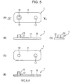
- An extrusion device 20 used for extrusion includes a single-opening die 21 (dice) corresponding to a planar shape of a band-plate-shaped section 11 to be obtained (see Fig. 5(A) ), and can perform extrusion in an isotropic pressure environment under ultrahigh pressure (up to about 1000 MPa).
- a positive-electrode blank 10A metal blank formed of the same metal (aluminum or an aluminum alloy) as that for a positive-electrode carrier 5 and a plus output terminal of a battery cell 2 is prepared in a bar form.
- a negative-electrode blank 11A metal blank formed of the same metal (copper or a copper alloy) as that for a negative-electrode carrier, a minus output terminal, and a minus terminal 6 of the battery cell 2 is prepared in a band form.
- a billet (composite blank) 1A entirely shaped like a thick round bar is prepared by winding the negative-electrode blank 11A around the bar-shaped positive-electrode blank 10A. At this time, the bar-shaped positive-electrode blank 10A is set to be shifted from the center portion of the thick round bar of the billet 1A.
- the negative-electrode blank 11A may be shaped like a hollow pipe in which the bar-shaped positive-electrode blank 10A can be eccentrically inserted, and the positive-electrode blank 10A may be inserted in the negative-electrode blank 11 A to form the billet 1 A.
- the billet 1A is loaded in the extrusion device 20, and the extrusion device 20 is started in an isotropic pressure environment under ultrahigh pressure (up to 1000 MPa). Since the billet 1A is structured by winding the negative-electrode blank 11A around the positive-electrode blank 10A, as described above, the positive-electrode blank 10A and the negative-electrode blank 11A are pushed out in parallel (subjected to extrusion or drawing), and a molded part 1B is obtained in which the positive-electrode blank 10A and the negative-electrode blank 11 A are integrated by diffusion bonding.
- the opening area of the die 21 of the extrusion device 20 is smaller than the cross-sectional area of the billet 1A, when the billet 1A is passed through the die 21, it is compressed all around its circumference to plastically deform. After coming out of the die 21, a joint surface between the positive-electrode blank 10A and the negative-electrode blank 11A forms "an interface (diffusion-bonded portion) between an outer peripheral surface of a bar-shaped section 10 and an inner peripheral surface of a band-plate-shaped section 11.
- the negative-electrode blank 11A is subjected to cutting (milling) to a thickness of a band-plate-shaped section 11. Thereby, a band-plate-shaped section 11 is formed, and the positive-electrode blank 10A remains in a protruding state to form a bar-shaped section 10 and a raised portion 12 provided around the root of the bar-shaped section 10. Further, the portion having the thickness of the band-plate-shaped section 11 is subjected to boring to form a connecting hole 13, whereby an electrically conductive connecting member 1 is completed. Surface polishing or surface treatment may be performed as needed.
- the electrically conductive connecting member 1 thus produced is formed by integrating the bar-shaped section 10 formed of the same metal as that for the positive-electrode carrier 5 of the battery cell 2 and the band-plate-shaped section 11 formed of the same metal as that for the minus terminal 6 of the battery cell 2 through diffusion bonding. Hence, electrolytic corrosion does not occur and electric resistance is reduced in any portion of the electrically conductive connecting member 1. Moreover, the mechanical strength is excellent.
- Figs. 8 and 9 illustrate an electrically conductive connecting member 1 according to a first embodiment of the present invention.
- an embedded material 30 is embedded in a center portion of a band-plate-shaped section 11 in a plate thickness direction.
- the electrically conductive connecting member 1 of the first embodiment is also adopted for a plus output terminal of a battery cell 2 (see Figs. 1 and 2 ).
- a bar-shaped section 10 is formed of the same metal (aluminum or an aluminum alloy) as that for a positive-electrode carrier 5 and the plus output terminal of the battery cell 2
- the band-plate-shaped section 11 is formed of the same metal (copper or a copper alloy) as that for a positive-electrode carrier and a plus output terminal of the battery cell 2. This point is identical to that of the first reference example.
- the embedded material 30 is arranged at a position that is aligned with a portion of the band-plate-shaped section 11 to which the bar-shaped section 10 is connected (a position where the bar-shaped section 10 and the embedded material 30 overlap with each other in plan view). This embedded material 30 is provided not to reach the position of the connecting hole 13. However, specific dimensions of the embedded material 30 (e.g., shape and size in plan view, and thickness) are not limited particularly.
- the embedded material 30 is formed of the same metal as that for the bar-shaped section 10. That is, the embedded material 30 is formed of the same metal as that for the positive-electrode carrier 5 and the plus output terminal of the battery cell 2, more specifically, aluminum or an aluminum alloy.
- the bottom portion of the recess 32 that is, the upper face of the embedded material 30 exposed in the recess 32 is provided with a raised portion 33 that surrounds the root of the bar-shaped section 10.
- the raised portion 33 is a filling portion (e.g., beads, a base material, or a welding material) to be produced in a welding process when the bar-shaped section 10 is connected to the embedded material 30 by welding.
- a fitting hole or a fitting recess for the bar-shaped section 10 is formed in the embedded material 30 before welding, positioning and holding can be easily and reliably performed during welding.
- the raised portion 33 is effective in reinforcing a state in which the bar-shaped section 10 protrudes from the band-plate-shaped section 11 (embedded material 30).
- the raised portion 33 is received in the recess 32, but does not protrude from the surface of the band-plate-shaped section 11. In other words, it is useful to form the recess 32 when the bar-shaped section 10 is connected to the band-plate-shaped section 11 (embedded material 30), because the raised portion 33 does not protrude outside.
- An outer peripheral surface of the embedded material 30 and an inner peripheral surface of the band-plate-shaped section 11 are diffusion-bonded by die working under ultrahigh isotropic pressure. While the bar-shaped section 10 and the embedded material 30 are connected by welding, as described above, since the embedded material 30 and the bar-shaped section 10 are both formed of aluminum or an aluminum alloy, that is, formed of the same metal, an eutectic is not produced in a welded portion therebetween. Thus, electrolytic corrosion does not occur and the electric resistance is kept suppressed. Moreover, the mechanical strength is sufficient, and there is no problem.
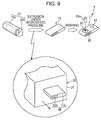
- extrusion is performed under ultrahigh hydrostatic pressure similarly to the first reference example, as illustrated in Fig. 9 .
- an extrusion device 20 used for extrusion includes a single-opening die 21 corresponding to a front shape of a band-plate-shaped section 11 to be obtained (see Fig. 5(B) illustrating the first reference example).
- the extrusion device 20 can perform extrusion in an isotropic pressure environment under ultrahigh pressure (up to about 1000 MPa).
- a positive-electrode blank 30A (metal blank) formed of the same metal as that for a bar-shaped section 10 is prepared, for example, in the form of a bar of elliptic cross section. Since the bar-shaped section 10 is formed of the same metal (aluminum or an aluminum alloy) as that for a positive-electrode carrier 5 and a plus output terminal of a battery cell 2, the positive-electrode blank 30A is also ultimately formed of the same metal as that for the positive-electrode carrier 5 and the plus output terminal of the battery cell 2.
- a negative-electrode blank 11 A (metal blank) formed of the same metal (copper or a copper alloy) as that for a negative-electrode carrier, a minus output terminal, and a minus terminal 6 of the battery cell 2 is prepared in a band form.
- a billet (composite blank) 1A entirely shaped like a thick round bar is prepared by winding the negative-electrode blank 11A around the bar-shaped positive-electrode blank 30A.
- the bar-shaped positive-electrode blank 30A is set to be shifted from the center portion of the thick round bar of the billet 1A.
- the billet 1A is loaded in the extrusion device 20, and the extrusion device 20 is started in an isotropic pressure environment under ultrahigh pressure (up to 1000 MPa). Since the billet 1A is structured by winding the negative-electrode blank 11A around the positive-electrode blank 30A, as described above, the positive-electrode blank 30A and the negative-electrode blank 11 A are pushed out in parallel (subjected to extrusion or drawing), and a molded part 1B is obtained in which the positive-electrode blank 30A and the negative-electrode blank 11A are integrated through diffusion bonding.
- the opening area of the die 21 of the extrusion device 20 is smaller than the cross-sectional area of the billet 1A, when the billet 1A is passed through the die 21, it is compressed all around its circumference to plastically deform. After coming out of the die 21, a joint surface between the blanks 30A and 11A forms "an interface (diffusion-bonded portion) between an outer peripheral surface of an embedded material 30 and an inner peripheral surface of a band-plate-shaped section 11.”
- the molded part 1B thus obtained is cut at a predetermined interval in an extruding direction.
- the cutting interval of the molded part 1 B corresponds to a size of a short side (width) of a rectangle of the band-plate-shaped section 11 in plan view.
- a portion of the bar-shaped negative-electrode blank 11A near one longitudinal end is subjected to cutting (milling) to form a recess 32 (a recess of a depth that allows an upper surface of an embedded material 30 to be exposed), and a portion near the other longitudinal end is subjected to boring to form a connecting hole 13, whereby a band-plate-shaped section 11 is formed.
- a positive-electrode blank 10A shaped like a round bar and formed of the same metal (aluminum or an aluminum alloy) blank (metal blank) as that for the positive-electrode carrier 5 and the plus output terminal of the battery cell 2 is prepared, and the positive-electrode blank 10A (that is, a member to be a bar-shaped section 10) is connected to the embedded material 30 exposed in the recess 32 of the band-plate-shaped section 11 by welding. In this way, an electrically conductive connecting member 1 is completed. Surface polishing or surface treatment may be performed as needed.
- the bar-shaped section 10 and the band-plate-shaped section 11 are diffusion-bonded with the embedded material 30 electrically combined with the bar-shaped section 10 being disposed therebetween. That is, in the electrically conductive connecting member 1 of the first embodiment, the bonding area (contact area) of the diffusion-bonded portion is increased by the presence of the embedded material 30, compared with the electrically conductive connecting member 1 of the first embodiment in which the bar-shaped section 10 and the band-plate-shaped section 11 are directly diffusion-bonded.
- the electrically conductive connecting member 1 of the first embodiment is more suitable for conduction of large current than the electrically conductive connecting member 1 of the first reference example.
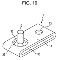
- Figs. 10 and 11 illustrate an electrically conductive connecting member 1 according to a second embodiment of the present invention.
- the electrically conductive connecting member 1 of the second embodiment is substantially similar to the first embodiment (see Fig. 8 ), and an embedded material 30 is embedded in a center portion in a plate thickness direction of a band-plate-shaped section 11, as illustrated in Fig. 10 .
- the greatest difference of the electrically conductive connecting member 1 of the second embodiment from the first embodiment is that the embedded material 30 is embedded in the overall longitudinal direction of the entire band-plate-shaped section 11. That is, the embedded material 30 reaches both a portion where a bar-shaped section 10 is connected to the band-plate-shaped section 11 and a position where a connecting hole 13 is formed.
- the second embodiment is identical to the first embodiment in that the embedded material 30 is formed of the same metal (aluminum or an aluminum alloy) as that for the bar-shaped section 10 and in that a recess 32 is provided in the band-plate-shaped section 11 and the bar-shaped section 10 is connected to the embedded material 30 that forms a bottom of the recess 32 by welding.
- the embedded material 30 is formed of the same metal (aluminum or an aluminum alloy) as that for the bar-shaped section 10 and in that a recess 32 is provided in the band-plate-shaped section 11 and the bar-shaped section 10 is connected to the embedded material 30 that forms a bottom of the recess 32 by welding.
- the electrically conductive connecting member 1 of the second embodiment is produced in a manner similar to that adopted in the first embodiment except that a positive-electrode blank 30A (metal blank) for forming the embedded material 30 is prepared in a round bar form and a negative-electrode blank 11A is wound around the positive-electrode blank 30A to form a billet (composite blank) 1A that is shaped like a thick round bar entirely formed by two concentric circles.
- a positive-electrode blank 30A metal blank
- a negative-electrode blank 11A is wound around the positive-electrode blank 30A to form a billet (composite blank) 1A that is shaped like a thick round bar entirely formed by two concentric circles.
- the electrically conductive connecting member 1 of the second embodiment since the size of the embedded material 30 is larger than in the electrically conductive connecting member 1 of the first embodiment, the bonding area (contact area) of a diffusion-bonded portion is increased. Hence, the electrically conductive connecting member 1 of the second embodiment is more suitable for conduction of large current.
- the embedded material 30 is exposed in an inner peripheral surface of the connecting hole 13 provided in the band-plate-shaped section 11.
- a minus terminal 6 of a battery cell 2 When a minus terminal 6 of a battery cell 2 is inserted in the connecting hole 13, it is brought into contact with the embedded material 30.
- the minus terminal 6 inserted in the connecting hole 13 is also reliably in contact with the band-plate-shaped section 11 that clamps the embedded material 30 from both front and back sides. For this reason, continuity is ensured between the band-plate-shaped section 11 and the minus terminal 6 that are formed of the same metal and have low electric resistance, and there is no problem.
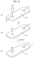
- Figs. 12(A) to 12(C) illustrate an electrically conductive connecting member 1 according to a second reference example.
- the electrically conductive connecting member 1 of the second reference example is substantially identical to the electrically conductive connecting member 1 of the first reference example (see Fig. 4 ) in appearance (a band-plate-shaped section 11 is shaped like a completely flat plate, but does not have a raised portion 12 that surrounds the root of a bar-shaped section 10).
- the electrically conductive connecting member 1 of the second reference example is characterized in a production method therefor.
- a negative-electrode blank 11A metal blank
- a positive-electrode blank 10A metal blank
- the negative-electrode blank 11 A is formed of the same metal (copper or a copper alloy) as that for a negative-electrode carrier, a minus output terminal, and a minus terminal 6 of a battery cell 2 (see Fig. 1 ), and is shaped in an outer form as the band-plate-shaped section 11 (a rectangular plate having round-chamfered four corners).
- An attachment hole 45 to which the positive-electrode blank 10A is to be connected is provided in a portion near one longitudinal end of the negative-electrode blank 11A, and a connecting hole 13 is provided in a portion near the other longitudinal end.
- the opening area of the attachment hole 45 is smaller than the cross-sectional area of the bar-shaped section 10 (positive-electrode blank 10A).
- the positive-electrode blank 10A is formed of the same metal (aluminum or an aluminum alloy) as that for a positive-electrode carrier 5 and a plus output terminal of the battery cell 2 (see Fig. 1 ), and is shaped in an outer form (round bar form) as the bar-shaped section 10.
- the positive-electrode blank 10A is press-fitted in the attachment hole 45 of the negative-electrode blank 11A. Press-fitting is performed so that the positive-electrode blank 10A is held protruding from the negative-electrode blank 11A.
- the positive-electrode blank 10A is press-fitted from one side of the attachment hole 45 to protrude to the other side of the attachment hole 45 (so that the positive-electrode blank 10A temporarily passes through the attachment hole 45 in almost the entire length).
- the positive-electrode blank 10A held protruding from the attachment hole 45 forms a bar-shaped section 10, and an electrically conductive connecting member 1 can be completed.
- Surface polishing or surface treatment may be performed as needed.
- the negative-electrode blank 11A and the positive-electrode blank 10A are plastically deformed in the radial direction and in the press-fitting direction between an inner peripheral surface of the attachment hole 45 and an outer peripheral surface of the bar-shaped section 10.
- an interface between the inner peripheral surface of the attachment hole 45 and the outer peripheral surface of the bar-shaped section 10 forms "a diffusion-bonded portion.”
- the bar-shaped section 10 formed of the same metal as that for the positive-electrode carrier 5 of the battery cell 2 and the band-plate-shaped section 11 formed of the same metal as that for the minus terminal 6 of the battery cell 2 are integrated through diffusion bonding. Hence, electrolytic corrosion does not occur and electric resistance can be reduced in any portion of the electrically conductive connecting member 1. Moreover, mechanical strength is high.
- Figs. 13(A) to 13(C) illustrate an electrically conductive connecting member 1 according to a third reference example.
- the electrically conductive connecting member 1 of the third reference example is substantially identical to the electrically conductive connecting member 1 of the first embodiment (see Fig. 8 ) in appearance, and an embedded material 30 is embedded in a center portion of a band-plate-shaped section 11 in a plate thickness direction to be aligned with a portion to which a bar-shaped section 10 is to be connected.
- the embedded material 30 is provided not to reach a position where a connecting hole 13 is to be formed (the band-plate-shaped section 11 does not have a recess 32 that surrounds the root of the bar-shaped section 10).
- a billet (composite blank) 1A shaped like a thick round bar in which a positive-electrode blank 30A is eccentrically provided is obtained by winding a negative-electrode blank 11A around the positive-electrode blank 30A, the billet 1A is subjected to extrusion or drawing with an extrusion device 20 capable of extrusion under a ultrahigh hydrostatic pressure, and a molded part 1 B is formed in which the positive-electrode blank 30A and the negative-electrode blank 11A are integrated through diffusion bonding.
- the molded part 1B thus obtained is cut to a dimension of a short side of a rectangle of the band-plate-shaped section 11 in plan view.
- an attachment hole 45 to which the positive-electrode blank 10A is to be connected is formed in a portion of the band-plate-shaped negative-electrode blank 11A near one longitudinal end, and a connecting hole 13 is formed in a portion near the other longitudinal end.
- the opening area of the attachment hole 45 is set to be smaller than the cross-sectional area of a bar-shaped section 10 (positive-electrode blank 10A).
- the positive-electrode blank 10A is press-fitted in the attachment hole 45 of the negative-electrode blank 11A so as to be held protruding from the negative-electrode blank 11A, as illustrated in Fig. 13(B) .
- a bar-shaped section 10 is formed by the positive-electrode blank 10A held protruding from the attachment hole 45, and an electrically conductive connecting member 1 can be completed. Surface polishing or surface treatment may be performed as needed.
- an electrically conductive connecting member 1 in which an embedded material 30 is embedded in almost the entire band-plate-shaped section 11 can also be produced, similarly to the electrically conductive connecting member 1 of the second embodiment (see Fig. 10 ).
- the bar-shaped section 10 is in contact with the band-plate-shaped section 11. Since the bar-shaped section 10 is also reliably in contact with the embedded material 30 of the same metal, electrical continuity can be ensured reliably.
- the electrically conductive connecting member 1 used as the plus output terminal is illustrated in the previous embodiments and examples, it may be adopted as the minus output terminal.
- the bar-shaped section 10 is formed of the same metal (copper or a copper alloy) as that for the negative-electrode carrier of the battery cell 2
- the band-plate-shaped section 11 is formed of the same metal (aluminum or an aluminum alloy) as that for the positive-electrode carrier 5 of the battery cell 2.
- the embedded material 30 when the embedded material 30 is adopted, it is formed of the same metal (copper or a copper alloy) as that for the negative-electrode carrier of the battery cell 2, similarly to the bar-shaped section 10.
- the electrically conductive connecting member 1 of the present invention is extremely suitable for connection of a car-mounted lithium ion battery, it can be used for connection of a lithium ion battery (battery) in other use without any problem.
- the connecting hole 13 does not always need to be formed in the band-plate-shaped section 11.
- a projecting bar section to be connected to the output terminal of a polarity different from that of the output terminal connected to the bar-shaped section 10 can be provided integrally with the band-plate-shaped section 11.
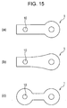
- the planar shape of the electrically conductive connecting member 1, that is, the planar shape of the band-plate-shaped section 11 is not limited to the rectangular shape. As illustrated in Figs. 15(a) to 15(c) , various shapes, such as a spoon shape, a paddle shape, and a gourd shape, can be adopted.
- a high-performance and high-reliability electrically conductive connecting member that is suitable for a battery including a plus output terminal and a minus output terminal formed of different metals, that can suppress electric resistance while preventing electrolytic corrosion, and that is excellent in mechanical strength.
- this electrically conductive connecting member can be used alone for various batteries, it is possible to produce a battery in which the electrically conductive connecting member of the present invention is assembled as one electrode beforehand and to offer the battery including the electrically conductive connecting member to a market.
Description
- The present invention relates to an electrically conductive connecting member that is suitable for use in a battery including a plus output terminal and a minus output terminal composed of different metals, a production method for the electrically conductive connecting member, and a battery equipped with the electrically conductive connecting member as an electrode.
- As a battery to be mounted in an electric car, a hybrid car, etc., there is known an assembled battery obtained by connecting a plurality of battery cells such that positive and negative electrodes thereof are connected in series (for example, see
JP 2002-373638 A - A bus bar (a component used to distribute electric energy) is a component that connects terminals of such battery cells. As a production method for such a bus bar, for example, members that constitute the bus bar are subjected to laser beam welding, as disclosed in
JP 2003-163039 A - Further,
EP 1 160 893 A2 - When battery cells are connected in series, as described above, a plus output terminal (aluminum) and a minus output terminal (copper) are connected by a bus bar. For this reason, the bus bar and one of the terminals are necessarily connected by connection of different kinds of metals whichever the bus bar is formed of aluminum or copper.
- In general, it is well known that, when different kinds of metals are connected, electrolytic corrosion (electrochemical corrosion) occurs via moisture in the air. Therefore, as this electrolytic corrosion proceeds, electrical continuity between the bus bar and the terminal is broken or the bus bar or the terminal itself is damaged. Finally, this leads to a serious problem in that the electric car cannot be started.
- As a solution to this problem,
JP 2003-163039 A - To fundamentally solve the above problem, it is essential not only to improve the bus bar, but also to improve and develop other members, for example, an electrode terminal provided in a battery cell.
- The present invention has been made in view of the above circumstances, and provides an electrically conductive connecting member that has both a structure and operation of an electrode terminal and a structure and operation of a bus bar and that is suitable for use in a battery including a plus output terminal and a minus output terminal composed of different metals. Further, an object of the invention is to provide a high-performance and high-reliability electrically conductive connecting member that reduces electric resistance while preventing electrolytic corrosion and that is excellent in mechanical strength, and a production method for the electrically conductive connecting member.
- To achieve the above object, the present invention takes the following measures.
- That is, an electrically conductive connecting member according to the present invention is an electrically conductive connecting member for power output that is used for a battery including a pair of output terminals formed of different metals, and includes an electrode section connectable to one of the output terminals and formed of the same metal as that for the one of the output terminals, and a bus bar section connected to the electrode section and formed of the same metal as that for the other output terminal. The electrode section and the bus bar section are integrated with each other through diffusion bonding. The electrode section is a columnar bar-shaped section. The bus bar section is a band-plate-shaped section connected to one end of the bar-shaped section and extending in a direction away from an axial center of the bar-shaped section, wherein the bar-shaped section protrudes from the band-plate-shaped section, wherein an embedded material formed of the same metal as that for the bar-shaped section is embedded in a center portion of the band-plate-shaped section in a plate thickness direction, wherein the band-plate-shaped section has a recess that surrounds the bar-shaped section so that an upper face of the embedded material is exposed in a bottom portion of the recess; wherein the bar-shaped section is connected to the embedded material, and wherein an outer peripheral surface of the embedded material and an inner peripheral surface of the band-plate-shaped section are diffusion-bonded.
- Here, the term "output terminal" refers to a positive-electrode carrier or a negative-electrode carrier included in a battery cell or the like or a portion having continuity to the carrier.
- Further, the term "diffusion bonding" refers to a state in which different metals to be bonded form a bonding interface where the metals are in tight contact with each other on the metal tissue level, and as a result, electrical conductivity and mechanical bonding strength of a bonded body are lower on the single metal side than at the interface.
- Through the use of this electrically conductive connecting member, the plus output terminal and the minus output terminal of the battery cell are formed of the same metal in appearance, electrolytic corrosion in the terminal connecting portion and the increase in electric resistance due to electrolytic corrosion are reduced, and this not only enhances reliability of the assembled battery, but also enhances reliability of a connecting portion (bus bar section) between battery cells. In addition, since the electrode section (bar-shaped section) and the bus bar section (band-plate-shaped section) of the electrically conductive connecting member are integrated through diffusion bonding, electrolytic corrosion and the increase in electric resistance due to electrolytic corrosion do not occur in the bonded portion.
- Preferably, when the electrically conductive connecting member is adopted for a plus output terminal of a lithium ion battery, the bar-shaped section is formed of aluminum or an aluminum alloy and the band-plate-shaped section is formed of copper or a copper alloy.
- Preferably, when the electrically conductive connecting member is adopted for a minus output terminal of a lithium ion battery, the bar-shaped section is formed of copper or a copper alloy and the band-plate-shaped section is formed of aluminum or an aluminum alloy.
- To produce the above-described electrically conductive connecting member (in which the embedded material is embedded in the center portion of the band-plate-shaped section in the plate thickness direction), a production method can be adopted which includes preparing a composite blank including a metal blank that forms the embedded material and that is formed of the same material as the bar-shaped section and a metal blank that surrounds the metal blank for the embedded material and forms the band-plate-shaped section, loading the composite blank in an extrusion device and starting the extrusion device under ultrahigh pressure of up to 1000 MPa, wherein a die of the extrusion device is smaller than the cross-sectional area of the composite blank, so that when the composite blank is passed through the die, the composite blank is compressed to plastically deform, whereby a molded part is achieved; cutting the molded part at a predetermined interval in accordance with the width of the band-plate-shaped section; cutting the band-plate-shaped section to form a recess so that a part of the embedded material is exposed to outside, and welding the bar-shaped section to the exposed part of the embedded material.
- By adopting this production method, an electrically conductive connecting member can be produced in which a metal material that forms a bar-shaped section and a metal material that forms a band-plate-shaped section are integrated through diffusion bonding and electrolytic corrosion does not occur.
- A battery according to the present invention includes the above-described electrically conductive connecting member or an electrically conductive connecting member produced by the above-described production method.
- According to the present invention, it is possible to realize a high-performance and high-reliability electrically conductive connecting member that is suitable for a battery including a plus output terminal and a minus output terminal formed of different metals, that can suppress electric resistance while preventing electrolytic corrosion, and that is excellent in mechanical strength.
- While this electrically conductive connecting member can be used alone for various batteries, it is possible to produce a battery in which the electrically conductive connecting member of the present invention is assembled as one electrode beforehand and to offer the battery including the electrically conductive connecting member to a market.
-
- [
Fig. 1] Fig. 1 is a perspective view of an assembled battery formed using electrically conductive connecting members according to a first reference example. - [
Fig. 2] Fig. 2 is a perspective view of a battery cell using an electrically conductive connecting member of the first reference example. - [
Fig. 3] Fig. 3 is a side view of the battery cell using the electrically conductive connecting member of the first reference example. - [
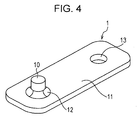
Fig. 4] Fig. 4 is a perspective view of the electrically conductive connecting member of the first reference example. - [
Fig. 5] Figs. 5(A), 5(B), 5(C), 5(D), and 5(E) are a plan view, a front view, a bottom view, a right side view, and a cross-sectional view, taken along line A-A ofFig. 5(A) , respectively, illustrating the electrically conductive connecting member of the first reference example. - [
Fig. 6] Fig. 6 is a perspective view illustrating a procedure for producing the electrically conductive connecting member of the first reference example. - [
Fig. 7] Fig. 7 is a perspective view of a modification of the electrically conductive connecting member of the first reference example. - [
Fig. 8] Fig. 8 is a perspective view of an electrically conductive connecting member according to a first embodiment. - [
Fig. 9] Fig. 9 is a perspective view illustrating a procedure for producing the electrically conductive connecting member of the first embodiment. - [
Fig. 10] Fig. 10 is a perspective view of an electrically conductive connecting member according to a second embodiment. - [
Fig. 11] Fig. 11 is a perspective view illustrating a procedure for producing the electrically conductive connecting member of the second embodiment. - [
Fig. 12] Figs. 12(A) to 12(C) are perspective views illustrating in order steps of producing an electrically conductive connecting member according to a second reference example, andFig. 12(C) is a perspective view illustrating a completed state. - [
Fig. 13] Figs. 13(A) to 13(C) are perspective views illustrating in order steps of producing an electrically conductive connecting member according to a third reference example, andFig. 13(C) is a perspective view illustrating a completed state. - [
Fig. 14] Fig. 14 is a perspective view of a modification of the electrically conductive connecting member of the third reference example. - [
Fig. 15] Figs. 15(a) to 15(c) are plan views illustrating modifications of an electrically conductive connecting member. - Embodiments of the present invention and Examples will be described below with reference to the drawings.
-
Figs. 1 to 6 illustrate an electrically conductive connectingmember 1 according to a first reference example. - As illustrated in
Figs. 1 to 3 , the electrically conductive connectingmember 1 is incorporated as one electrode of abattery 2. By this electrode (electrically conductive connecting member 1), a plurality ofbattery cells 2 can be connected in series to form an assembledbattery 4. That is, eachbattery cell 2 is connected via an electrically conductive connectingmember 1 serving as an electrode of a plus output terminal (plus output side) thereof to a minus output terminal (minus output side) of anotherbattery cell 2. - Each
battery cell 2 is a lithium-ion battery, and a plus output terminal (plus output side) thereof is formed of aluminum or an aluminum alloy. This is because, as illustrated inFig. 3 , a positive-electrode carrier 5 provided in the battery cell 2 (a base body for fixing electrons and ions) is formed of aluminum or an aluminum alloy and the plus output terminal provided integrally with or separately from the positive-electrode carrier 5 with continuity is formed of aluminum or an aluminum alloy. In contrast, a minus output terminal of thebattery cell 2 is formed of copper or a copper alloy. At the minus output terminal, aminus terminal 6 protrudes upward from an upper end of thebattery cell 2. An outer peripheral surface of theminus terminal 6 is threaded externally. - As illustrated in
Figs. 1 to 5 , the electrically conductive connecting member 1 (electrode) includes a columnar bar-shaped section 10 (electrode section), and a band-plate-shaped section 11 (bus bar section) that is connected to one end of the bar-shapedsection 10 and extends in a direction away from an axial center of the bar-shapedsection 10. - An axial direction of the bar-shaped
section 10 and a plate-surface extending direction of the band-plate-shapedsection 11 are orthogonal to each other. A connecting portion between the bar-shapedsection 10 and the band-plate-shapedsection 11 has a structure such that the band-plate-shapedsection 11 is fitted on the one end of the bar-shaped section 10 (the one end of the bar-shapedsection 10 penetrates through the band-plate-shaped section 11). In the illustrated example, an end of the bar-shapedsection 10 connected to the band-plate-shapedsection 11 and penetrating through the band-plate-shapedsection 11 is flush with a surface of the band-plate-shapedsection 11. However, alternatively, the bar-shapedsection 10 penetrating through the band-plate-shapedsection 11 may further slightly protrude from the band-plate-shapedsection 11. - The bar-shaped
section 10 is shaped like a round bar, and the band-plate-shapedsection 11 is shaped like a rectangular plate round-chamfered at four corners in plan view. The thickness of the bar-shapedsection 10 is substantially constant, and the thickness of the band-plate-shapedsection 11 is substantially constant. - The band-plate-shaped
section 11 has a raisedportion 12 that surrounds the root of the bar-shapedsection 10. The raisedportion 12 is raised by the influence of the edge shape of a cutting tool during a procedure for producing the electrically conductive connecting member 1 (cutting step), and has a round concave face provided all around its circumference. An end of the band-plate-shapedsection 11 opposite a side of the bar-shapedsection 10 has a connectinghole 13 provided through the band-plate-shapedsection 11 in a plate thickness direction. - The raised
portion 12 is not always necessary as a structure of the electrically conductive connectingmember 1. However, the raisedportion 12 is effective in reinforcing a protruding state of the bar-shapedsection 10 from the band-plate-shapedsection 11 and in being used as an index of the amount by which the band-plate-shapedsection 11 floats from the battery cell 2 (ensuring a floating state) when the electrically conductive connectingmember 1 is attached to thebattery cell 2. - In the first reference example, the outer diameter of the bar-shaped
section 10 is set at 5 to 25 mm, and the protruding length of the bar-shapedsection 10 from the band-plate-shapedsection 11 is set at 10 to 100 mm. The inner diameter of the connectinghole 13 provided in the band-plate-shapedsection 11 is set to be suitable to receive theminus terminal 6 provided on the battery cell 2 (nominal diameter is about 4 to 12 mm). While the dimensions of the band-plate-shapedsection 11 can be appropriately changed according to the connection distance betweenbattery cells 2 and the amount of current, for example, for example, the long side length is 30 to 70 mm, the short side length is 20 to 60 mm, and the thickness is 1 to 2 mm. - The bar-shaped
section 10 and the band-plate-shapedsection 11 are formed of different kinds of metals. As described above, when the electrically conductive connectingmember 1 is adopted for the plus output terminal of thebattery cell 2, the bar-shapedsection 10 is formed of the same metal as that for the positive-electrode carrier 5 and the plus output terminal of thebattery cell 2, that is, formed of aluminum or an aluminum alloy. The band-plate-shapedsection 11 is formed of the same metal as that for a negative-electrode carrier, the minus output terminal, and theminus terminal 6 of thebattery cell 2, that is, formed of copper or a copper alloy. - An outer peripheral surface of a portion of the bar-shaped
section 10 extending through the band-plate-shapedsection 11 and an inner peripheral surface of a portion of the band-plate-shapedsection 11 fitted on the bar-shaped section 10 (that is, a contact portion between the bar-shapedsection 10 and the band-plate-shaped section 11) are subjected to diffusion bonding. Here, the term diffusion bonding refers to a state in which the metal (Al) of the bar-shapedsection 10 and the metal (Cu) of the band-plate-shapedsection 11 are deformed under ultrahigh pressure (e.g., about 1000 MPa) to form a binding interface where the metals are in tight contact with each other on the metal tissue level, and as a result, electrical conductivity and mechanical binding structure are increased to "values practically suitable for the electrically conductive connectingmember 1." - As illustrated in
Fig. 3 , when the electrically conductive connectingmember 1 having such a structure is attached to thebattery cell 2, the portion of the bar-shapedsection 10 protruding from the band-plate-shapedsection 11 is used as an internal connectingportion 15. That is, the internal connectingportion 15 is electrically connected to the plus output terminal of the battery cell 2 (a portion provided integrally with or separately from the positive-electrode carrier 5). Further, the connectinghole 13 provided in the band-plate-shapedsection 11 is fitted on aminus terminal 6 of abattery cell 2 to be connected, and a copper nut 16 (seeFig. 1 ) formed of the same metal as that for the band-plate-shapedsection 11 is screwed on the protruding minus terminal 6 (externally threaded portion). - Instead of screwing the
nut 16 for bonding, theminus terminal 6 may be inserted in the connectinghole 13 of the band-plate-shapedsection 11 and theminus terminal 6 and the connectinghole 13 may then be welded together. In this case, since the portions of the same metal are welded, no electrical and mechanical problems occur. - In this case, the bar-shaped section 10 (internal connecting portion 15) of the electrically conductive connecting
member 1 and the plus output terminal (portion formed integrally with or separately from the positive-electrode carrier 5) of thebattery cell 2 are connected by connection of the same metal, and therefore, electrolytic corrosion does not occur. Further, the band-plate-shaped section 11 (the inner surface of the connectinghole 13 serving as an external connecting portion) of the electrically conductive connectingmember 1, and the outer surface of theminus terminal 6 of thebattery cell 2 and thenut 16 are also connected by connection of the same metal. Hence, electrolytic corrosion does not occur. - In addition, while the bar-shaped
section 10 and the band-plate-shapedsection 11 of the electrically conductive connectingmember 1 are formed of different metals, they are diffusion-bonded, and therefore, electrolytic corrosion does not occur. Also, the bar-shapedsection 10 and the band-plate-shapedsection 11 are kept in a state in which the electric resistance is suppressed. - As results of these, in the assembled
battery 4 formed by connecting a plurality ofbattery cells 2 in series by the electrically conductive connectingmember 1 of the present invention, electrolytic corrosion does not occur in any connecting portion, and high-efficiency conductivity is ensured. Further, since the electrically conductive connectingmember 1 has excellent mechanical strength, it does not bend or break in a normal use condition. - In the first reference example, the bar-shaped
section 10 is lightweight because it is formed of aluminum or an aluminum alloy, and this can reduce the weight of the assembledbattery 4. For this reason, the first reference example is useful in weight reduction of an electric car in which the assembledbattery 4 is mounted as a battery. - To produce the electrically conductive connecting
member 1 having such a structure, extrusion is performed under high or ultrahigh hydrostatic pressure, as illustrated inFig. 6 . - An
extrusion device 20 used for extrusion includes a single-opening die 21 (dice) corresponding to a planar shape of a band-plate-shapedsection 11 to be obtained (seeFig. 5(A) ), and can perform extrusion in an isotropic pressure environment under ultrahigh pressure (up to about 1000 MPa). - In a production procedure for the electrically conductive connecting
member 1, first, a positive-electrode blank 10A (metal blank) formed of the same metal (aluminum or an aluminum alloy) as that for a positive-electrode carrier 5 and a plus output terminal of abattery cell 2 is prepared in a bar form. Also, a negative-electrode blank 11A (metal blank) formed of the same metal (copper or a copper alloy) as that for a negative-electrode carrier, a minus output terminal, and aminus terminal 6 of thebattery cell 2 is prepared in a band form. - A billet (composite blank) 1A entirely shaped like a thick round bar is prepared by winding the negative-
electrode blank 11A around the bar-shaped positive-electrode blank 10A. At this time, the bar-shaped positive-electrode blank 10A is set to be shifted from the center portion of the thick round bar of thebillet 1A. The negative-electrode blank 11A may be shaped like a hollow pipe in which the bar-shaped positive-electrode blank 10A can be eccentrically inserted, and the positive-electrode blank 10A may be inserted in the negative-electrode blank 11 A to form thebillet 1 A. - Next, the
billet 1A is loaded in theextrusion device 20, and theextrusion device 20 is started in an isotropic pressure environment under ultrahigh pressure (up to 1000 MPa). Since thebillet 1A is structured by winding the negative-electrode blank 11A around the positive-electrode blank 10A, as described above, the positive-electrode blank 10A and the negative-electrode blank 11A are pushed out in parallel (subjected to extrusion or drawing), and a moldedpart 1B is obtained in which the positive-electrode blank 10A and the negative-electrode blank 11 A are integrated by diffusion bonding. - Since the opening area of the
die 21 of theextrusion device 20 is smaller than the cross-sectional area of thebillet 1A, when thebillet 1A is passed through thedie 21, it is compressed all around its circumference to plastically deform. After coming out of the die 21, a joint surface between the positive-electrode blank 10A and the negative-electrode blank 11A forms "an interface (diffusion-bonded portion) between an outer peripheral surface of a bar-shapedsection 10 and an inner peripheral surface of a band-plate-shapedsection 11. - The molded
part 1B thus obtained is cut at a predetermined interval in an extruding direction. Since thedie 21 of theextrusion device 20 has the opening shaped correspondingly to the planar shape of the band-plate-shaped section 11 (seeFig. 5(A) ) in the first reference example, the cutting interval of the moldedpart 1 B is set in accordance with the length of the bar-shapedsection 10, which corresponds to the height of the electrically conductive connectingmember 1. - After being cut, the negative-
electrode blank 11A is subjected to cutting (milling) to a thickness of a band-plate-shapedsection 11. Thereby, a band-plate-shapedsection 11 is formed, and the positive-electrode blank 10A remains in a protruding state to form a bar-shapedsection 10 and a raisedportion 12 provided around the root of the bar-shapedsection 10. Further, the portion having the thickness of the band-plate-shapedsection 11 is subjected to boring to form a connectinghole 13, whereby an electrically conductive connectingmember 1 is completed. Surface polishing or surface treatment may be performed as needed. - The electrically conductive connecting
member 1 thus produced is formed by integrating the bar-shapedsection 10 formed of the same metal as that for the positive-electrode carrier 5 of thebattery cell 2 and the band-plate-shapedsection 11 formed of the same metal as that for theminus terminal 6 of thebattery cell 2 through diffusion bonding. Hence, electrolytic corrosion does not occur and electric resistance is reduced in any portion of the electrically conductive connectingmember 1. Moreover, the mechanical strength is excellent. - In the first reference example, the shapes and outer dimensions of the bar-shaped
section 10 and the band-plate-shapedsection 11 are not limited. For example, as illustrated inFig. 7 , the connecting strength of the band-plate-shapedsection 11 may be increased by enlarging a portion around the connectinghole 13 in a plate surface direction. Further, the four corners of the band-plate-shapedsection 11 may be subjected to angular chamfering instead of round chamfering, or chamfering may be omitted (angular corners may be formed). Alternatively, the band-plate-shapedsection 11 may be entirely shaped like a long circle in plan view. The bar-shapedsection 10 can be shaped like a square bar. -
Figs. 8 and9 illustrate an electrically conductive connectingmember 1 according to a first embodiment of the present invention. As illustrated inFig. 8 , in the electrically conductive connectingmember 1 of the second embodiment, an embeddedmaterial 30 is embedded in a center portion of a band-plate-shapedsection 11 in a plate thickness direction. - The electrically conductive connecting
member 1 of the first embodiment is also adopted for a plus output terminal of a battery cell 2 (seeFigs. 1 and2 ). For this reason, a bar-shapedsection 10 is formed of the same metal (aluminum or an aluminum alloy) as that for a positive-electrode carrier 5 and the plus output terminal of thebattery cell 2, and the band-plate-shapedsection 11 is formed of the same metal (copper or a copper alloy) as that for a positive-electrode carrier and a plus output terminal of thebattery cell 2. This point is identical to that of the first reference example. A connectinghole 13, which penetrates through the band-plate-shapedsection 11 in the plate thickness direction, is provided in an end portion of the band-plate-shapedsection 11 opposite a side where the bar-shapedsection 10 is provided. This point is also identical to that of the first reference example. - The embedded
material 30 is arranged at a position that is aligned with a portion of the band-plate-shapedsection 11 to which the bar-shapedsection 10 is connected (a position where the bar-shapedsection 10 and the embeddedmaterial 30 overlap with each other in plan view). This embeddedmaterial 30 is provided not to reach the position of the connectinghole 13. However, specific dimensions of the embedded material 30 (e.g., shape and size in plan view, and thickness) are not limited particularly. - The embedded
material 30 is formed of the same metal as that for the bar-shapedsection 10. That is, the embeddedmaterial 30 is formed of the same metal as that for the positive-electrode carrier 5 and the plus output terminal of thebattery cell 2, more specifically, aluminum or an aluminum alloy. - The band-plate-shaped
section 11 has arecess 32 that surrounds the bar-shapedsection 10 in the portion to which the bar-shapedsection 10 is connected. An upper face of the embeddedmaterial 30 is exposed in a bottom portion of therecess 32. Therecess 32 may be formed by slightly digging the upper face of the embeddedmaterial 30. In any case, the bottom portion of therecess 32 is formed by the embeddedmaterial 30. The aperture size of therecess 32 is preferably set to fit in the size of the embeddedmaterial 30 in plan view. - The bottom portion of the
recess 32, that is, the upper face of the embeddedmaterial 30 exposed in therecess 32 is provided with a raisedportion 33 that surrounds the root of the bar-shapedsection 10. The raisedportion 33 is a filling portion (e.g., beads, a base material, or a welding material) to be produced in a welding process when the bar-shapedsection 10 is connected to the embeddedmaterial 30 by welding. When a fitting hole or a fitting recess for the bar-shapedsection 10 is formed in the embeddedmaterial 30 before welding, positioning and holding can be easily and reliably performed during welding. - The raised
portion 33 is effective in reinforcing a state in which the bar-shapedsection 10 protrudes from the band-plate-shaped section 11 (embedded material 30). - The raised
portion 33 is received in therecess 32, but does not protrude from the surface of the band-plate-shapedsection 11. In other words, it is useful to form therecess 32 when the bar-shapedsection 10 is connected to the band-plate-shaped section 11 (embedded material 30), because the raisedportion 33 does not protrude outside. - An outer peripheral surface of the embedded
material 30 and an inner peripheral surface of the band-plate-shapedsection 11 are diffusion-bonded by die working under ultrahigh isotropic pressure. While the bar-shapedsection 10 and the embeddedmaterial 30 are connected by welding, as described above, since the embeddedmaterial 30 and the bar-shapedsection 10 are both formed of aluminum or an aluminum alloy, that is, formed of the same metal, an eutectic is not produced in a welded portion therebetween. Thus, electrolytic corrosion does not occur and the electric resistance is kept suppressed. Moreover, the mechanical strength is sufficient, and there is no problem. - As a result, electrolytic corrosion does not occur between the bar-shaped
section 10 and the band-plate-shapedsection 11, and the electric resistance is kept suppressed. This point is identical to that of the first reference example. - To produce the electrically conductive connecting
member 1 of the first embodiment, extrusion is performed under ultrahigh hydrostatic pressure similarly to the first reference example, as illustrated inFig. 9 . - Unlike the first reference example, however, an
extrusion device 20 used for extrusion includes a single-opening die 21 corresponding to a front shape of a band-plate-shapedsection 11 to be obtained (seeFig. 5(B) illustrating the first reference example). Similarly to the first reference example, theextrusion device 20 can perform extrusion in an isotropic pressure environment under ultrahigh pressure (up to about 1000 MPa). - In a production procedure for the electrically conductive connecting
member 1, first, a positive-electrode blank 30A (metal blank) formed of the same metal as that for a bar-shapedsection 10 is prepared, for example, in the form of a bar of elliptic cross section. Since the bar-shapedsection 10 is formed of the same metal (aluminum or an aluminum alloy) as that for a positive-electrode carrier 5 and a plus output terminal of abattery cell 2, the positive-electrode blank 30A is also ultimately formed of the same metal as that for the positive-electrode carrier 5 and the plus output terminal of thebattery cell 2. - Also, a negative-
electrode blank 11 A (metal blank) formed of the same metal (copper or a copper alloy) as that for a negative-electrode carrier, a minus output terminal, and aminus terminal 6 of thebattery cell 2 is prepared in a band form. - Then, a billet (composite blank) 1A entirely shaped like a thick round bar is prepared by winding the negative-
electrode blank 11A around the bar-shaped positive-electrode blank 30A. At this time, the bar-shaped positive-electrode blank 30A is set to be shifted from the center portion of the thick round bar of thebillet 1A. - Next, the
billet 1A is loaded in theextrusion device 20, and theextrusion device 20 is started in an isotropic pressure environment under ultrahigh pressure (up to 1000 MPa). Since thebillet 1A is structured by winding the negative-electrode blank 11A around the positive-electrode blank 30A, as described above, the positive-electrode blank 30A and the negative-electrode blank 11 A are pushed out in parallel (subjected to extrusion or drawing), and a moldedpart 1B is obtained in which the positive-electrode blank 30A and the negative-electrode blank 11A are integrated through diffusion bonding. - Further, since the opening area of the
die 21 of theextrusion device 20 is smaller than the cross-sectional area of thebillet 1A, when thebillet 1A is passed through thedie 21, it is compressed all around its circumference to plastically deform. After coming out of the die 21, a joint surface between theblanks material 30 and an inner peripheral surface of a band-plate-shapedsection 11." - The molded
part 1B thus obtained is cut at a predetermined interval in an extruding direction. The cutting interval of the moldedpart 1 B corresponds to a size of a short side (width) of a rectangle of the band-plate-shapedsection 11 in plan view. - After being cut, a portion of the bar-shaped negative-
electrode blank 11A near one longitudinal end is subjected to cutting (milling) to form a recess 32 (a recess of a depth that allows an upper surface of an embeddedmaterial 30 to be exposed), and a portion near the other longitudinal end is subjected to boring to form a connectinghole 13, whereby a band-plate-shapedsection 11 is formed. - Further, a positive-
electrode blank 10A shaped like a round bar and formed of the same metal (aluminum or an aluminum alloy) blank (metal blank) as that for the positive-electrode carrier 5 and the plus output terminal of thebattery cell 2 is prepared, and the positive-electrode blank 10A (that is, a member to be a bar-shaped section 10) is connected to the embeddedmaterial 30 exposed in therecess 32 of the band-plate-shapedsection 11 by welding. In this way, an electrically conductive connectingmember 1 is completed. Surface polishing or surface treatment may be performed as needed. - In the electrically conductive connecting
member 1 of the first embodiment, the bar-shapedsection 10 and the band-plate-shapedsection 11 are diffusion-bonded with the embeddedmaterial 30 electrically combined with the bar-shapedsection 10 being disposed therebetween. That is, in the electrically conductive connectingmember 1 of the first embodiment, the bonding area (contact area) of the diffusion-bonded portion is increased by the presence of the embeddedmaterial 30, compared with the electrically conductive connectingmember 1 of the first embodiment in which the bar-shapedsection 10 and the band-plate-shapedsection 11 are directly diffusion-bonded. - For this reason, the electrically conductive connecting
member 1 of the first embodiment is more suitable for conduction of large current than the electrically conductive connectingmember 1 of the first reference example. - In the electrically conductive connecting
member 1 of the first embodiment, other structures, operating effects, and usage are substantially identical to those adopted in the first reference example and detailed descriptions thereof are skipped here. -
Figs. 10 and11 illustrate an electrically conductive connectingmember 1 according to a second embodiment of the present invention. - The electrically conductive connecting
member 1 of the second embodiment is substantially similar to the first embodiment (seeFig. 8 ), and an embeddedmaterial 30 is embedded in a center portion in a plate thickness direction of a band-plate-shapedsection 11, as illustrated inFig. 10 . - The greatest difference of the electrically conductive connecting
member 1 of the second embodiment from the first embodiment is that the embeddedmaterial 30 is embedded in the overall longitudinal direction of the entire band-plate-shapedsection 11. That is, the embeddedmaterial 30 reaches both a portion where a bar-shapedsection 10 is connected to the band-plate-shapedsection 11 and a position where a connectinghole 13 is formed. - The second embodiment is identical to the first embodiment in that the embedded
material 30 is formed of the same metal (aluminum or an aluminum alloy) as that for the bar-shapedsection 10 and in that arecess 32 is provided in the band-plate-shapedsection 11 and the bar-shapedsection 10 is connected to the embeddedmaterial 30 that forms a bottom of therecess 32 by welding. - Further, as illustrated in
Fig. 10 , the electrically conductive connectingmember 1 of the second embodiment is produced in a manner similar to that adopted in the first embodiment except that a positive-electrode blank 30A (metal blank) for forming the embeddedmaterial 30 is prepared in a round bar form and a negative-electrode blank 11A is wound around the positive-electrode blank 30A to form a billet (composite blank) 1A that is shaped like a thick round bar entirely formed by two concentric circles. - In the electrically conductive connecting
member 1 of the second embodiment, since the size of the embeddedmaterial 30 is larger than in the electrically conductive connectingmember 1 of the first embodiment, the bonding area (contact area) of a diffusion-bonded portion is increased. Hence, the electrically conductive connectingmember 1 of the second embodiment is more suitable for conduction of large current. - The embedded
material 30 is exposed in an inner peripheral surface of the connectinghole 13 provided in the band-plate-shapedsection 11. When aminus terminal 6 of abattery cell 2 is inserted in the connectinghole 13, it is brought into contact with the embeddedmaterial 30. However, theminus terminal 6 inserted in the connectinghole 13 is also reliably in contact with the band-plate-shapedsection 11 that clamps the embeddedmaterial 30 from both front and back sides. For this reason, continuity is ensured between the band-plate-shapedsection 11 and theminus terminal 6 that are formed of the same metal and have low electric resistance, and there is no problem. - Other structures, operating effects, and usage of the electrically conductive connecting
member 1 of the second embodiment are substantially identical to those adopted in the first embodiment, and detailed descriptions thereof are skipped here. -
Figs. 12(A) to 12(C) illustrate an electrically conductive connectingmember 1 according to a second reference example. - The electrically conductive connecting
member 1 of the second reference example is substantially identical to the electrically conductive connectingmember 1 of the first reference example (seeFig. 4 ) in appearance (a band-plate-shapedsection 11 is shaped like a completely flat plate, but does not have a raisedportion 12 that surrounds the root of a bar-shaped section 10). - The electrically conductive connecting
member 1 of the second reference example is characterized in a production method therefor. - That is, to produce the electrically conductive connecting
member 1, first, a negative-electrode blank 11A (metal blank) to form a band-plate-shapedsection 11 and a positive-electrode blank 10A (metal blank) to form a bar-shapedsection 10 are prepared, as illustrated inFig. 12(A) . - The negative-
electrode blank 11 A is formed of the same metal (copper or a copper alloy) as that for a negative-electrode carrier, a minus output terminal, and aminus terminal 6 of a battery cell 2 (seeFig. 1 ), and is shaped in an outer form as the band-plate-shaped section 11 (a rectangular plate having round-chamfered four corners). - An
attachment hole 45 to which the positive-electrode blank 10A is to be connected is provided in a portion near one longitudinal end of the negative-electrode blank 11A, and a connectinghole 13 is provided in a portion near the other longitudinal end. The opening area of theattachment hole 45 is smaller than the cross-sectional area of the bar-shaped section 10 (positive-electrode blank 10A). - The positive-
electrode blank 10A is formed of the same metal (aluminum or an aluminum alloy) as that for a positive-electrode carrier 5 and a plus output terminal of the battery cell 2 (seeFig. 1 ), and is shaped in an outer form (round bar form) as the bar-shapedsection 10. - Then, as illustrated in
Fig. 12(B) , the positive-electrode blank 10A is press-fitted in theattachment hole 45 of the negative-electrode blank 11A. Press-fitting is performed so that the positive-electrode blank 10A is held protruding from the negative-electrode blank 11A. Preferably, the positive-electrode blank 10A is press-fitted from one side of theattachment hole 45 to protrude to the other side of the attachment hole 45 (so that the positive-electrode blank 10A temporarily passes through theattachment hole 45 in almost the entire length). - In this way, as illustrated in
Fig. 12(C) , the positive-electrode blank 10A held protruding from theattachment hole 45 forms a bar-shapedsection 10, and an electrically conductive connectingmember 1 can be completed. Surface polishing or surface treatment may be performed as needed. - By the above-described press-fitting, the negative-
electrode blank 11A and the positive-electrode blank 10A are plastically deformed in the radial direction and in the press-fitting direction between an inner peripheral surface of theattachment hole 45 and an outer peripheral surface of the bar-shapedsection 10. As a result, an interface between the inner peripheral surface of theattachment hole 45 and the outer peripheral surface of the bar-shapedsection 10 forms "a diffusion-bonded portion." - In the electrically conductive connecting
member 1 thus produced, the bar-shapedsection 10 formed of the same metal as that for the positive-electrode carrier 5 of thebattery cell 2 and the band-plate-shapedsection 11 formed of the same metal as that for theminus terminal 6 of thebattery cell 2 are integrated through diffusion bonding. Hence, electrolytic corrosion does not occur and electric resistance can be reduced in any portion of the electrically conductive connectingmember 1. Moreover, mechanical strength is high. - Other structures, operating effects, and usage of the electrically conductive connecting
member 1 of the second reference example are substantially identical to those adopted in the first reference example, and detailed descriptions thereof are skipped here. -
Figs. 13(A) to 13(C) illustrate an electrically conductive connectingmember 1 according to a third reference example. - The electrically conductive connecting
member 1 of the third reference example is substantially identical to the electrically conductive connectingmember 1 of the first embodiment (seeFig. 8 ) in appearance, and an embeddedmaterial 30 is embedded in a center portion of a band-plate-shapedsection 11 in a plate thickness direction to be aligned with a portion to which a bar-shapedsection 10 is to be connected. The embeddedmaterial 30 is provided not to reach a position where a connectinghole 13 is to be formed (the band-plate-shapedsection 11 does not have arecess 32 that surrounds the root of the bar-shaped section 10). - When the electrically conductive connecting
member 1 of the third reference example is produced, similarly to the production method for the electrically conductive connectingmember 1 of the first embodiment (seeFig. 9 ), a billet (composite blank) 1A shaped like a thick round bar in which a positive-electrode blank 30A is eccentrically provided is obtained by winding a negative-electrode blank 11A around the positive-electrode blank 30A, thebillet 1A is subjected to extrusion or drawing with anextrusion device 20 capable of extrusion under a ultrahigh hydrostatic pressure, and a moldedpart 1 B is formed in which the positive-electrode blank 30A and the negative-electrode blank 11A are integrated through diffusion bonding. - The molded
part 1B thus obtained is cut to a dimension of a short side of a rectangle of the band-plate-shapedsection 11 in plan view. - After cutting, an
attachment hole 45 to which the positive-electrode blank 10A is to be connected is formed in a portion of the band-plate-shaped negative-electrode blank 11A near one longitudinal end, and a connectinghole 13 is formed in a portion near the other longitudinal end. The opening area of theattachment hole 45 is set to be smaller than the cross-sectional area of a bar-shaped section 10 (positive-electrode blank 10A). - After that, substantially similarly to the production method for the electrically conductive connecting
member 1 of the second reference example (seeFigs. 12(B) and 12(C) ), the positive-electrode blank 10A is press-fitted in theattachment hole 45 of the negative-electrode blank 11A so as to be held protruding from the negative-electrode blank 11A, as illustrated inFig. 13(B) . - In this way, as illustrated in
Fig. 13(C) , a bar-shapedsection 10 is formed by the positive-electrode blank 10A held protruding from theattachment hole 45, and an electrically conductive connectingmember 1 can be completed. Surface polishing or surface treatment may be performed as needed. - As a result of the above-described press fitting, a bonding interface between an inner peripheral surface of the
attachment hole 45 and an outer peripheral surface of the bar-shapedsection 10 forms "a diffusion-bonded portion", similarly to the second reference example. - Other structures, operating effects, and usage of the electrically conductive connecting
member 1 of the third reference example are substantially identical to those adopted in the first embodiment, and detailed descriptions thereof are skipped here. - According to this production method, as illustrated in
Fig. 14 , an electrically conductive connectingmember 1 in which an embeddedmaterial 30 is embedded in almost the entire band-plate-shapedsection 11 can also be produced, similarly to the electrically conductive connectingmember 1 of the second embodiment (seeFig. 10 ). - In the electrically conductive connecting
member 1 ofFigs. 13 and14 , the bar-shapedsection 10 is in contact with the band-plate-shapedsection 11. Since the bar-shapedsection 10 is also reliably in contact with the embeddedmaterial 30 of the same metal, electrical continuity can be ensured reliably. - For example, while the electrically conductive connecting
member 1 used as the plus output terminal is illustrated in the previous embodiments and examples, it may be adopted as the minus output terminal. In this case, preferably, the bar-shapedsection 10 is formed of the same metal (copper or a copper alloy) as that for the negative-electrode carrier of thebattery cell 2, and the band-plate-shapedsection 11 is formed of the same metal (aluminum or an aluminum alloy) as that for the positive-electrode carrier 5 of thebattery cell 2. Needless to say, when the embeddedmaterial 30 is adopted, it is formed of the same metal (copper or a copper alloy) as that for the negative-electrode carrier of thebattery cell 2, similarly to the bar-shapedsection 10. - While the electrically conductive connecting
member 1 of the present invention is extremely suitable for connection of a car-mounted lithium ion battery, it can be used for connection of a lithium ion battery (battery) in other use without any problem. - The connecting
hole 13 does not always need to be formed in the band-plate-shapedsection 11. For example, a projecting bar section to be connected to the output terminal of a polarity different from that of the output terminal connected to the bar-shapedsection 10 can be provided integrally with the band-plate-shapedsection 11. - The planar shape of the electrically conductive connecting
member 1, that is, the planar shape of the band-plate-shapedsection 11 is not limited to the rectangular shape. As illustrated inFigs. 15(a) to 15(c) , various shapes, such as a spoon shape, a paddle shape, and a gourd shape, can be adopted. - According to the present invention, it is possible to realize a high-performance and high-reliability electrically conductive connecting member that is suitable for a battery including a plus output terminal and a minus output terminal formed of different metals, that can suppress electric resistance while preventing electrolytic corrosion, and that is excellent in mechanical strength.
- While this electrically conductive connecting member can be used alone for various batteries, it is possible to produce a battery in which the electrically conductive connecting member of the present invention is assembled as one electrode beforehand and to offer the battery including the electrically conductive connecting member to a market.
-
- 1:
- electrically conductive connecting member
- 1A:
- billet
- 1B:
- molded part
- 2:
- battery cell
- 4:
- assembled battery
- 5:
- positive-electrode carrier
- 6:
- minus terminal
- 10:
- bar-shaped section
- 10A:
- positive-electrode blank
- 11:
- band-plate-shaped section
- 11A:
- negative-electrode blank
- 12:
- raised portion
- 13:
- connecting hole
- 15:
- internal connecting portion
- 16:
- nut
- 20:
- extrusion device
- 21:
- die
- 30:
- embedded material
- 30A:
- positive-electrode blank
- 32:
- recess
- 33:
- raised portion
- 45:
- attachment hole
Claims (4)
- An electrically conductive connecting member (1) for power output that is used for a battery (2) including a pair of output terminals formed of different metals, the electrically conductive connecting member (1) comprising:an electrode section (10) connectable to one of the output terminals and formed of the same metal as that for the one of the output terminals, and a bus bar section (11) connected to the electrode section (10) and formed of the same metal as that for the other output terminal,wherein the electrode section (10) and the bus bar section (11) are integrated with each other through diffusion bonding,characterized in that:the electrode section (10) is a columnar bar-shaped section,the bus bar section (11) is a band-plate-shaped section connected to one end of the bar-shaped section and extending in a direction away from an axial center of the bar-shaped section,wherein the bar-shaped section protrudes from the band-plate-shaped section,wherein an embedded material (30) formed of the same metal as that for the bar-shaped section is embedded in a center portion of the band-plate-shaped section in a plate thickness direction,wherein the band-plate-shaped section has a recess (32) that surrounds the bar-shaped section so that an upper face of the embedded material (30) is exposed in a bottom portion of the recess (32);wherein the bar-shaped section is connected to the embedded material (30), andwherein an outer peripheral surface of the embedded material (30) and an inner peripheral surface of the band-plate-shaped section are diffusion-bonded.
- The electrically conductive connecting member according to Claim 1,
wherein one of the bar-shaped section and the band-plate-shaped section is formed of aluminum or an aluminum alloy, and
wherein the other of the bar-shaped section and the band-plate-shaped section is formed of copper or a copper alloy. - A production method for the electrically conductive connecting member according to Claim 1, the production method comprising:preparing a composite blank (1A) including a metal blank (30A) that forms the embedded material (30) and that is formed of the same material as the bar-shaped section and a metal blank (11A) that surrounds the metal blank (30A) for the embedded material and forms the band-plate-shaped section;loading the composite blank (1A) in an extrusion device (20) and starting the extrusion device (20) in an isotropic pressure environment under ultrahigh pressure of up to 1000 MPa, wherein a die (21) of the extrusion device (20) is smaller than the cross-sectional area of the composite blank (1A), so that when the composite blank (1A) is passed through the die (21), the composite blank (1A) is compressed to plastically deform, whereby a molded part (1 B) is achieved;cutting the molded part (1 B) at a predetermined interval in accordance with the width of the band-plate-shaped section;cutting the band-plate-shaped section to form a recess (32), so that a part of the embedded material (30) is exposed to outside; andwelding the bar-shaped section to the exposed part of the embedded material (30).
- A battery comprising the electrically conductive connecting member according to Claim 1 or 2.
Applications Claiming Priority (2)
| Application Number | Priority Date | Filing Date | Title |
|---|---|---|---|
| JP2010232448A JP5570383B2 (en) | 2010-10-15 | 2010-10-15 | Conductive connecting member, method of manufacturing conductive connecting member, and battery having conductive connecting member as electrode |
| PCT/JP2011/073587 WO2012050173A1 (en) | 2010-10-15 | 2011-10-13 | Electrically conductive connecting member, process for manufacturing electrically conductive connecting member, and battery equipped with electrically conductive connecting member as electrode |
Publications (3)
| Publication Number | Publication Date |
|---|---|
| EP2581966A1 EP2581966A1 (en) | 2013-04-17 |
| EP2581966A4 EP2581966A4 (en) | 2014-01-15 |
| EP2581966B1 true EP2581966B1 (en) | 2016-08-31 |
Family
ID=45938394
Family Applications (1)
| Application Number | Title | Priority Date | Filing Date |
|---|---|---|---|
| EP11832604.0A Active EP2581966B1 (en) | 2010-10-15 | 2011-10-13 | Electrically conductive connecting member, process for manufacturing electrically conductive connecting member, and battery equipped with electrically conductive connecting member as electrode |
Country Status (10)
| Country | Link |
|---|---|
| US (1) | US9136617B2 (en) |
| EP (1) | EP2581966B1 (en) |
| JP (1) | JP5570383B2 (en) |
| KR (2) | KR101494983B1 (en) |
| CN (1) | CN103003979B (en) |
| ES (1) | ES2592514T3 (en) |
| HU (1) | HUE030693T2 (en) |
| PL (1) | PL2581966T3 (en) |
| TW (1) | TWI469427B (en) |
| WO (1) | WO2012050173A1 (en) |
Families Citing this family (32)
| Publication number | Priority date | Publication date | Assignee | Title |
|---|---|---|---|---|
| KR20160046920A (en) * | 2010-03-29 | 2016-04-29 | 가부시키가이샤 고베 세이코쇼 | Bus bar and method for producing bus bar |
| US9553294B2 (en) | 2011-12-16 | 2017-01-24 | Gs Yuasa International Ltd. | Electric storage device, manufacturing method of electric storage device, and bus bar used for electric storage device |
| DE102012208352A1 (en) * | 2012-05-18 | 2013-11-21 | Robert Bosch Gmbh | Method for connecting two battery poles of two battery cells consisting of dissimilar materials and battery unit |
| JP5868265B2 (en) * | 2012-05-25 | 2016-02-24 | 日立オートモティブシステムズ株式会社 | Single cells and batteries |
| JP5929733B2 (en) * | 2012-12-10 | 2016-06-08 | 株式会社豊田自動織機 | Storage module and secondary battery module |
| JP2014130740A (en) * | 2012-12-28 | 2014-07-10 | Hitachi Metals Ltd | Method of manufacturing electrode terminal connector |
| JP2014143158A (en) * | 2012-12-28 | 2014-08-07 | Hitachi Metals Ltd | Method of manufacturing electrode terminal connector |
| US9252550B2 (en) | 2012-12-28 | 2016-02-02 | Hitachi Metals, Ltd. | Electrode terminal connector producing method |
| KR101590986B1 (en) * | 2013-03-05 | 2016-02-03 | 주식회사 엘지화학 | Method of Bonding Electrode Terminal or Busbar Using Diffusion Bonding |
| EP2937916B1 (en) * | 2013-07-05 | 2020-05-06 | LG Chem, Ltd. | Battery module including connection members comprised of dissimilar metals |
| US9698403B2 (en) * | 2013-09-06 | 2017-07-04 | Johnson Controls Technology Company | High current interconnect system and method for use in a battery module |
| DE202013012314U1 (en) * | 2013-10-08 | 2016-04-27 | Engeser Gmbh Innovative Verbindungstechnik | Electrical connection and battery cell contact |
| JP6616058B2 (en) * | 2014-01-28 | 2019-12-04 | 住友電装株式会社 | Terminal and aluminum wire connection structure of the terminal |
| CN104117776B (en) * | 2014-07-17 | 2016-04-13 | 大族激光科技产业集团股份有限公司 | The method for laser welding of high reflecting metal parts |
| KR101741704B1 (en) | 2014-12-01 | 2017-05-30 | 최범진 | A Connecting Terminal Unit of Battery Pack and A Method for Connecting Battery Pack |
| DE102015100149A1 (en) | 2015-01-08 | 2016-07-14 | Raimund Huber | Electrical functional component with contact pin and method for producing an electrical functional component |
| US10403875B2 (en) | 2015-04-14 | 2019-09-03 | Ford Global Technologies, Llc | Busbar assembly for vehicle traction battery |
| KR102490863B1 (en) | 2015-11-04 | 2023-01-20 | 삼성에스디아이 주식회사 | Manufacturing method for secondary battery |
| DE102016202873A1 (en) * | 2016-02-24 | 2017-08-24 | Bayerische Motoren Werke Aktiengesellschaft | Method for producing an electrical connection element and connection element for battery cells |
| CA2921925A1 (en) | 2016-02-25 | 2017-08-25 | Hydro-Quebec | Electric battery assembly |
| KR20170135062A (en) * | 2016-05-30 | 2017-12-08 | 삼성에스디아이 주식회사 | Battery module |
| US10062975B2 (en) | 2016-06-01 | 2018-08-28 | Termaco Ltee | Battery connector |
| KR101913250B1 (en) | 2017-01-13 | 2018-12-31 | 안동대학교 산학협력단 | Electrode connecting tag and secondary battery package with the same |
| JP6741215B2 (en) * | 2017-01-20 | 2020-08-19 | 株式会社オートネットワーク技術研究所 | Connection module |
| CN107538124B (en) * | 2017-09-26 | 2021-03-16 | 东莞市大为工业科技有限公司 | Diffusion connection method for lithium battery composite electrode |
| CN111033811B (en) * | 2017-12-22 | 2023-03-24 | 松下知识产权经营株式会社 | Battery laminate |
| CN109623060A (en) * | 2018-12-03 | 2019-04-16 | 合肥晶澳太阳能科技有限公司 | A kind of welding method of photovoltaic component terminal box |
| KR102450418B1 (en) | 2018-12-07 | 2022-09-30 | 주식회사 엘지에너지솔루션 | Battery module with improved safety, battery pack comprising the battery module and vehicle comprising the same |
| USD928088S1 (en) * | 2019-02-27 | 2021-08-17 | A.F.W. Co., Ltd. | Bus bar for fuses |
| CN111384607A (en) * | 2020-03-20 | 2020-07-07 | 重庆中科超容科技有限公司 | Split easy-to-detach bus |
| KR20210127009A (en) * | 2020-04-13 | 2021-10-21 | 주식회사 엘지에너지솔루션 | Battery module and method of manufacturing the same |
| CN112563671A (en) * | 2020-12-16 | 2021-03-26 | 张家港华捷电子有限公司 | Connection structure of lithium electricity protection shield and group battery |
Citations (2)
| Publication number | Priority date | Publication date | Assignee | Title |
|---|---|---|---|---|
| GB2299701A (en) * | 1995-04-07 | 1996-10-09 | Paul Philip Stockton | Cellular battery |
| EP2393144A1 (en) * | 2009-02-02 | 2011-12-07 | GS Yuasa International Ltd. | Conductor for connecting terminals, assembled battery, and method for producing assembled battery |
Family Cites Families (25)
| Publication number | Priority date | Publication date | Assignee | Title |
|---|---|---|---|---|
| US6156452A (en) | 1997-10-07 | 2000-12-05 | Matsushita Electric Indsutrial Co., Ltd. | Non-aqueous electrolyte secondary cell |
| JP4146000B2 (en) * | 1998-08-31 | 2008-09-03 | 松下電器産業株式会社 | Connection structure between batteries |
| US6844110B2 (en) | 2000-05-24 | 2005-01-18 | Ngk Insulators, Ltd. | Lithium secondary cell and assembly thereof |
| JP2002151045A (en) * | 2000-11-10 | 2002-05-24 | Honda Motor Co Ltd | Bus bar for battery module and battery module |
| JP2002358945A (en) * | 2000-11-15 | 2002-12-13 | Ngk Insulators Ltd | Connection structure of lithium secondary unit cells |
| JP4029585B2 (en) | 2001-06-18 | 2008-01-09 | 日産自動車株式会社 | Bus bar and battery using bus bar |
| JP2003123733A (en) | 2001-10-18 | 2003-04-25 | Sony Corp | Electrode for battery and lithium ion polymer battery, and method of manufacturing the same |
| JP2003163039A (en) | 2001-11-27 | 2003-06-06 | Yazaki Corp | Coupling structure of bus bar |
| US7776467B2 (en) * | 2005-07-05 | 2010-08-17 | Panasonic Corporation | Inter-battery connection device |
| JP2007134233A (en) * | 2005-11-11 | 2007-05-31 | Toyota Motor Corp | Battery terminal structure |
| JP2007280898A (en) | 2006-04-12 | 2007-10-25 | Toyota Motor Corp | Terminal connection structure, power storage mechanism, and electric vehicle |
| JP4416770B2 (en) * | 2006-09-07 | 2010-02-17 | 日立ビークルエナジー株式会社 | Assembled battery |
| JP2010103053A (en) * | 2008-10-27 | 2010-05-06 | Toyota Motor Corp | Battery module, and method of manufacturing battery module |
| CN102598361B (en) * | 2009-06-08 | 2015-08-26 | 巴伐利亚机动车制造厂 | Battery connector |
| JP5528746B2 (en) * | 2009-09-11 | 2014-06-25 | 三洋電機株式会社 | Assembled battery |
| US9196890B2 (en) * | 2009-10-05 | 2015-11-24 | Samsung Sdi Co., Ltd. | Battery module with welded portion between terminals |
| US8460818B2 (en) * | 2009-10-05 | 2013-06-11 | Samsung Sdi Co., Ltd. | Battery module |
| KR20110055255A (en) * | 2009-11-19 | 2011-05-25 | 에스비리모티브 주식회사 | Bus bar and battery module with the same |
| JP5481178B2 (en) * | 2009-12-08 | 2014-04-23 | 日立ビークルエナジー株式会社 | Battery pack and single battery |
| US9105911B2 (en) * | 2009-12-28 | 2015-08-11 | Samsung Sdi Co., Ltd. | Battery module |
| KR101760450B1 (en) | 2010-02-25 | 2017-07-31 | 테크니칼 매터리알즈, 인코포레이티드, 디/비/에이 매터리온 테크니칼 매터리알즈 | Methods for creating side-by-side metallic bonds between different materials using solid-phase bonding and the products produced thereby |
| KR20160046920A (en) * | 2010-03-29 | 2016-04-29 | 가부시키가이샤 고베 세이코쇼 | Bus bar and method for producing bus bar |
| JP5523164B2 (en) | 2010-03-29 | 2014-06-18 | 株式会社神戸製鋼所 | Electrode terminal and method for manufacturing electrode terminal |
| JP5702947B2 (en) * | 2010-04-22 | 2015-04-15 | 矢崎総業株式会社 | Wiring material |
| JP5006484B1 (en) * | 2010-12-28 | 2012-08-22 | 株式会社Neomaxマテリアル | Battery terminal connection plate and method of manufacturing battery terminal connection plate |
-
2010
- 2010-10-15 JP JP2010232448A patent/JP5570383B2/en active Active
-
2011
- 2011-10-13 KR KR1020137009327A patent/KR101494983B1/en active IP Right Grant
- 2011-10-13 CN CN201180034349.1A patent/CN103003979B/en active Active
- 2011-10-13 ES ES11832604.0T patent/ES2592514T3/en active Active
- 2011-10-13 US US13/810,939 patent/US9136617B2/en active Active
- 2011-10-13 PL PL11832604T patent/PL2581966T3/en unknown
- 2011-10-13 KR KR1020147018150A patent/KR101765379B1/en active IP Right Grant
- 2011-10-13 HU HUE11832604A patent/HUE030693T2/en unknown
- 2011-10-13 EP EP11832604.0A patent/EP2581966B1/en active Active
- 2011-10-13 WO PCT/JP2011/073587 patent/WO2012050173A1/en active Application Filing
- 2011-10-14 TW TW100137331A patent/TWI469427B/en active
Patent Citations (2)
| Publication number | Priority date | Publication date | Assignee | Title |
|---|---|---|---|---|
| GB2299701A (en) * | 1995-04-07 | 1996-10-09 | Paul Philip Stockton | Cellular battery |
| EP2393144A1 (en) * | 2009-02-02 | 2011-12-07 | GS Yuasa International Ltd. | Conductor for connecting terminals, assembled battery, and method for producing assembled battery |
Also Published As
| Publication number | Publication date |
|---|---|
| PL2581966T3 (en) | 2017-02-28 |
| ES2592514T3 (en) | 2016-11-30 |
| CN103003979A (en) | 2013-03-27 |
| TW201232895A (en) | 2012-08-01 |
| JP5570383B2 (en) | 2014-08-13 |
| KR20140090274A (en) | 2014-07-16 |
| KR101494983B1 (en) | 2015-02-23 |
| CN103003979B (en) | 2015-07-01 |
| US9136617B2 (en) | 2015-09-15 |
| EP2581966A4 (en) | 2014-01-15 |
| WO2012050173A1 (en) | 2012-04-19 |
| KR101765379B1 (en) | 2017-08-07 |
| US20130130572A1 (en) | 2013-05-23 |
| HUE030693T2 (en) | 2017-05-29 |
| TWI469427B (en) | 2015-01-11 |
| KR20130080041A (en) | 2013-07-11 |
| JP2012089254A (en) | 2012-05-10 |
| EP2581966A1 (en) | 2013-04-17 |
Similar Documents
| Publication | Publication Date | Title |
|---|---|---|
| EP2581966B1 (en) | Electrically conductive connecting member, process for manufacturing electrically conductive connecting member, and battery equipped with electrically conductive connecting member as electrode | |
| EP2555281B1 (en) | Electrode terminal, and method for producing electrode terminal | |
| CN103227307B (en) | Rectangular secondary cell | |
| US8801444B2 (en) | Busbar and busbar manufacturing method | |
| JP5856858B2 (en) | Method for manufacturing prismatic secondary battery | |
| JP5523165B2 (en) | Bus bar manufacturing method | |
| US10062873B2 (en) | Secondary battery and battery pack using the same | |
| KR102115861B1 (en) | Connection body, method for manufacturing connection body, power storage element and method for manufacturing power storage element | |
| KR20110037943A (en) | Battery and method of manufacturing same | |
| JP5483348B2 (en) | Bus bar manufacturing method | |
| EP2717373A1 (en) | Electrode plate group unit for secondary battery and method for manufacturing same | |
| CN107665968B (en) | Secondary battery, method for manufacturing same, and assembled battery using same | |
| US8993155B2 (en) | Prismatic secondary battery | |
| JP6641842B2 (en) | Prismatic rechargeable battery | |
| WO2010074169A1 (en) | Sealing body for sealed battery and sealed battery using same | |
| CN104103850A (en) | Cylindrical lithium ion battery | |
| KR20220106055A (en) | Terminal component, secondary battery, and method for manufacturing terminal component | |
| EP4131632A1 (en) | Terminal component and method for manufacturing the same |
Legal Events
| Date | Code | Title | Description |
|---|---|---|---|
| PUAI | Public reference made under article 153(3) epc to a published international application that has entered the european phase |
Free format text: ORIGINAL CODE: 0009012 |
|
| 17P | Request for examination filed |
Effective date: 20130110 |
|
| AK | Designated contracting states |
Kind code of ref document: A1 Designated state(s): AL AT BE BG CH CY CZ DE DK EE ES FI FR GB GR HR HU IE IS IT LI LT LU LV MC MK MT NL NO PL PT RO RS SE SI SK SM TR |
|
| RIN1 | Information on inventor provided before grant (corrected) |
Inventor name: SAKAE ,AKIRA |
|
| RIN1 | Information on inventor provided before grant (corrected) |
Inventor name: SAKAE, AKIRA |
|
| A4 | Supplementary search report drawn up and despatched |
Effective date: 20131213 |
|
| RIC1 | Information provided on ipc code assigned before grant |
Ipc: H01M 10/0525 20100101ALN20131209BHEP Ipc: B23K 20/00 20060101ALI20131209BHEP Ipc: B21C 37/04 20060101ALI20131209BHEP Ipc: B23K 20/233 20060101ALI20131209BHEP Ipc: H01M 2/20 20060101AFI20131209BHEP Ipc: H01R 4/62 20060101ALI20131209BHEP Ipc: B21C 23/00 20060101ALI20131209BHEP Ipc: H01R 43/00 20060101ALI20131209BHEP Ipc: H01R 11/28 20060101ALI20131209BHEP Ipc: H01R 11/01 20060101ALI20131209BHEP Ipc: H01M 2/10 20060101ALI20131209BHEP Ipc: H01M 2/30 20060101ALI20131209BHEP |
|
| DAX | Request for extension of the european patent (deleted) | ||
| 17Q | First examination report despatched |
Effective date: 20141029 |
|
| GRAP | Despatch of communication of intention to grant a patent |
Free format text: ORIGINAL CODE: EPIDOSNIGR1 |
|
| RIC1 | Information provided on ipc code assigned before grant |
Ipc: H01M 2/30 20060101ALI20160311BHEP Ipc: B23K 20/02 20060101ALI20160311BHEP Ipc: B21C 23/00 20060101ALI20160311BHEP Ipc: H01M 2/20 20060101AFI20160311BHEP Ipc: H01R 11/28 20060101ALI20160311BHEP Ipc: H01M 2/10 20060101ALI20160311BHEP Ipc: H01M 10/0525 20100101ALN20160311BHEP |
|
| RIC1 | Information provided on ipc code assigned before grant |
Ipc: H01R 11/28 20060101ALI20160329BHEP Ipc: H01M 10/0525 20100101ALN20160329BHEP Ipc: B23K 20/02 20060101ALI20160329BHEP Ipc: H01M 2/20 20060101AFI20160329BHEP Ipc: B21C 23/00 20060101ALI20160329BHEP Ipc: H01R 4/10 20060101ALN20160329BHEP Ipc: H01M 2/30 20060101ALI20160329BHEP |
|
| INTG | Intention to grant announced |
Effective date: 20160413 |
|
| RIN1 | Information on inventor provided before grant (corrected) |
Inventor name: SAKAE, AKIRA |
|
| GRAS | Grant fee paid |
Free format text: ORIGINAL CODE: EPIDOSNIGR3 |
|
| GRAA | (expected) grant |
Free format text: ORIGINAL CODE: 0009210 |
|
| AK | Designated contracting states |
Kind code of ref document: B1 Designated state(s): AL AT BE BG CH CY CZ DE DK EE ES FI FR GB GR HR HU IE IS IT LI LT LU LV MC MK MT NL NO PL PT RO RS SE SI SK SM TR |
|
| REG | Reference to a national code |
Ref country code: CH Ref legal event code: EP Ref country code: GB Ref legal event code: FG4D |
|
| REG | Reference to a national code |
Ref country code: IE Ref legal event code: FG4D |
|
| REG | Reference to a national code |
Ref country code: DE Ref legal event code: R096 Ref document number: 602011029951 Country of ref document: DE |
|
| REG | Reference to a national code |
Ref country code: AT Ref legal event code: REF Ref document number: 825667 Country of ref document: AT Kind code of ref document: T Effective date: 20161015 |
|
| REG | Reference to a national code |
Ref country code: ES Ref legal event code: FG2A Ref document number: 2592514 Country of ref document: ES Kind code of ref document: T3 Effective date: 20161130 |
|
| REG | Reference to a national code |
Ref country code: LT Ref legal event code: MG4D |
|
| REG | Reference to a national code |
Ref country code: NL Ref legal event code: MP Effective date: 20160831 |
|
| REG | Reference to a national code |
Ref country code: AT Ref legal event code: MK05 Ref document number: 825667 Country of ref document: AT Kind code of ref document: T Effective date: 20160831 |
|
| PG25 | Lapsed in a contracting state [announced via postgrant information from national office to epo] |
Ref country code: RS Free format text: LAPSE BECAUSE OF FAILURE TO SUBMIT A TRANSLATION OF THE DESCRIPTION OR TO PAY THE FEE WITHIN THE PRESCRIBED TIME-LIMIT Effective date: 20160831 Ref country code: NO Free format text: LAPSE BECAUSE OF FAILURE TO SUBMIT A TRANSLATION OF THE DESCRIPTION OR TO PAY THE FEE WITHIN THE PRESCRIBED TIME-LIMIT Effective date: 20161130 Ref country code: HR Free format text: LAPSE BECAUSE OF FAILURE TO SUBMIT A TRANSLATION OF THE DESCRIPTION OR TO PAY THE FEE WITHIN THE PRESCRIBED TIME-LIMIT Effective date: 20160831 Ref country code: FI Free format text: LAPSE BECAUSE OF FAILURE TO SUBMIT A TRANSLATION OF THE DESCRIPTION OR TO PAY THE FEE WITHIN THE PRESCRIBED TIME-LIMIT Effective date: 20160831 Ref country code: LT Free format text: LAPSE BECAUSE OF FAILURE TO SUBMIT A TRANSLATION OF THE DESCRIPTION OR TO PAY THE FEE WITHIN THE PRESCRIBED TIME-LIMIT Effective date: 20160831 |
|
| PG25 | Lapsed in a contracting state [announced via postgrant information from national office to epo] |
Ref country code: BE Free format text: LAPSE BECAUSE OF NON-PAYMENT OF DUE FEES Effective date: 20161031 Ref country code: SE Free format text: LAPSE BECAUSE OF FAILURE TO SUBMIT A TRANSLATION OF THE DESCRIPTION OR TO PAY THE FEE WITHIN THE PRESCRIBED TIME-LIMIT Effective date: 20160831 Ref country code: AT Free format text: LAPSE BECAUSE OF FAILURE TO SUBMIT A TRANSLATION OF THE DESCRIPTION OR TO PAY THE FEE WITHIN THE PRESCRIBED TIME-LIMIT Effective date: 20160831 Ref country code: GR Free format text: LAPSE BECAUSE OF FAILURE TO SUBMIT A TRANSLATION OF THE DESCRIPTION OR TO PAY THE FEE WITHIN THE PRESCRIBED TIME-LIMIT Effective date: 20161201 Ref country code: NL Free format text: LAPSE BECAUSE OF FAILURE TO SUBMIT A TRANSLATION OF THE DESCRIPTION OR TO PAY THE FEE WITHIN THE PRESCRIBED TIME-LIMIT Effective date: 20160831 Ref country code: LV Free format text: LAPSE BECAUSE OF FAILURE TO SUBMIT A TRANSLATION OF THE DESCRIPTION OR TO PAY THE FEE WITHIN THE PRESCRIBED TIME-LIMIT Effective date: 20160831 |
|
| PG25 | Lapsed in a contracting state [announced via postgrant information from national office to epo] |
Ref country code: RO Free format text: LAPSE BECAUSE OF FAILURE TO SUBMIT A TRANSLATION OF THE DESCRIPTION OR TO PAY THE FEE WITHIN THE PRESCRIBED TIME-LIMIT Effective date: 20160831 Ref country code: EE Free format text: LAPSE BECAUSE OF FAILURE TO SUBMIT A TRANSLATION OF THE DESCRIPTION OR TO PAY THE FEE WITHIN THE PRESCRIBED TIME-LIMIT Effective date: 20160831 |
|
| REG | Reference to a national code |
Ref country code: DE Ref legal event code: R119 Ref document number: 602011029951 Country of ref document: DE |
|
| REG | Reference to a national code |
Ref country code: HU Ref legal event code: AG4A Ref document number: E030693 Country of ref document: HU |
|
| PG25 | Lapsed in a contracting state [announced via postgrant information from national office to epo] |
Ref country code: BE Free format text: LAPSE BECAUSE OF FAILURE TO SUBMIT A TRANSLATION OF THE DESCRIPTION OR TO PAY THE FEE WITHIN THE PRESCRIBED TIME-LIMIT Effective date: 20160831 Ref country code: SK Free format text: LAPSE BECAUSE OF FAILURE TO SUBMIT A TRANSLATION OF THE DESCRIPTION OR TO PAY THE FEE WITHIN THE PRESCRIBED TIME-LIMIT Effective date: 20160831 Ref country code: BG Free format text: LAPSE BECAUSE OF FAILURE TO SUBMIT A TRANSLATION OF THE DESCRIPTION OR TO PAY THE FEE WITHIN THE PRESCRIBED TIME-LIMIT Effective date: 20161130 Ref country code: SM Free format text: LAPSE BECAUSE OF FAILURE TO SUBMIT A TRANSLATION OF THE DESCRIPTION OR TO PAY THE FEE WITHIN THE PRESCRIBED TIME-LIMIT Effective date: 20160831 Ref country code: PT Free format text: LAPSE BECAUSE OF FAILURE TO SUBMIT A TRANSLATION OF THE DESCRIPTION OR TO PAY THE FEE WITHIN THE PRESCRIBED TIME-LIMIT Effective date: 20170102 Ref country code: DK Free format text: LAPSE BECAUSE OF FAILURE TO SUBMIT A TRANSLATION OF THE DESCRIPTION OR TO PAY THE FEE WITHIN THE PRESCRIBED TIME-LIMIT Effective date: 20160831 Ref country code: CZ Free format text: LAPSE BECAUSE OF FAILURE TO SUBMIT A TRANSLATION OF THE DESCRIPTION OR TO PAY THE FEE WITHIN THE PRESCRIBED TIME-LIMIT Effective date: 20160831 |
|
| REG | Reference to a national code |
Ref country code: CH Ref legal event code: PL |
|
| PG25 | Lapsed in a contracting state [announced via postgrant information from national office to epo] |
Ref country code: IT Free format text: LAPSE BECAUSE OF FAILURE TO SUBMIT A TRANSLATION OF THE DESCRIPTION OR TO PAY THE FEE WITHIN THE PRESCRIBED TIME-LIMIT Effective date: 20160831 |
|
| PLBE | No opposition filed within time limit |
Free format text: ORIGINAL CODE: 0009261 |
|
| STAA | Information on the status of an ep patent application or granted ep patent |
Free format text: STATUS: NO OPPOSITION FILED WITHIN TIME LIMIT |
|
| GBPC | Gb: european patent ceased through non-payment of renewal fee |
Effective date: 20161130 |
|
| REG | Reference to a national code |
Ref country code: IE Ref legal event code: MM4A |
|
| REG | Reference to a national code |
Ref country code: FR Ref legal event code: ST Effective date: 20170630 |
|
| PG25 | Lapsed in a contracting state [announced via postgrant information from national office to epo] |
Ref country code: DE Free format text: LAPSE BECAUSE OF NON-PAYMENT OF DUE FEES Effective date: 20170503 Ref country code: FR Free format text: LAPSE BECAUSE OF NON-PAYMENT OF DUE FEES Effective date: 20161102 Ref country code: CH Free format text: LAPSE BECAUSE OF NON-PAYMENT OF DUE FEES Effective date: 20161031 Ref country code: LI Free format text: LAPSE BECAUSE OF NON-PAYMENT OF DUE FEES Effective date: 20161031 |
|
| 26N | No opposition filed |
Effective date: 20170601 |
|
| PG25 | Lapsed in a contracting state [announced via postgrant information from national office to epo] |
Ref country code: LU Free format text: LAPSE BECAUSE OF NON-PAYMENT OF DUE FEES Effective date: 20161013 Ref country code: SI Free format text: LAPSE BECAUSE OF FAILURE TO SUBMIT A TRANSLATION OF THE DESCRIPTION OR TO PAY THE FEE WITHIN THE PRESCRIBED TIME-LIMIT Effective date: 20160831 |
|
| PG25 | Lapsed in a contracting state [announced via postgrant information from national office to epo] |
Ref country code: IE Free format text: LAPSE BECAUSE OF NON-PAYMENT OF DUE FEES Effective date: 20161013 Ref country code: GB Free format text: LAPSE BECAUSE OF NON-PAYMENT OF DUE FEES Effective date: 20161130 |
|
| PG25 | Lapsed in a contracting state [announced via postgrant information from national office to epo] |
Ref country code: CY Free format text: LAPSE BECAUSE OF FAILURE TO SUBMIT A TRANSLATION OF THE DESCRIPTION OR TO PAY THE FEE WITHIN THE PRESCRIBED TIME-LIMIT Effective date: 20160831 |
|
| PG25 | Lapsed in a contracting state [announced via postgrant information from national office to epo] |
Ref country code: IS Free format text: LAPSE BECAUSE OF FAILURE TO SUBMIT A TRANSLATION OF THE DESCRIPTION OR TO PAY THE FEE WITHIN THE PRESCRIBED TIME-LIMIT Effective date: 20160831 Ref country code: MK Free format text: LAPSE BECAUSE OF FAILURE TO SUBMIT A TRANSLATION OF THE DESCRIPTION OR TO PAY THE FEE WITHIN THE PRESCRIBED TIME-LIMIT Effective date: 20160831 Ref country code: MC Free format text: LAPSE BECAUSE OF FAILURE TO SUBMIT A TRANSLATION OF THE DESCRIPTION OR TO PAY THE FEE WITHIN THE PRESCRIBED TIME-LIMIT Effective date: 20160831 Ref country code: TR Free format text: LAPSE BECAUSE OF FAILURE TO SUBMIT A TRANSLATION OF THE DESCRIPTION OR TO PAY THE FEE WITHIN THE PRESCRIBED TIME-LIMIT Effective date: 20160831 Ref country code: MT Free format text: LAPSE BECAUSE OF NON-PAYMENT OF DUE FEES Effective date: 20161031 |
|
| PG25 | Lapsed in a contracting state [announced via postgrant information from national office to epo] |
Ref country code: AL Free format text: LAPSE BECAUSE OF FAILURE TO SUBMIT A TRANSLATION OF THE DESCRIPTION OR TO PAY THE FEE WITHIN THE PRESCRIBED TIME-LIMIT Effective date: 20160831 |
|
| P01 | Opt-out of the competence of the unified patent court (upc) registered |
Effective date: 20230523 |
|
| PGFP | Annual fee paid to national office [announced via postgrant information from national office to epo] |
Ref country code: PL Payment date: 20230830 Year of fee payment: 13 |
|
| PGFP | Annual fee paid to national office [announced via postgrant information from national office to epo] |
Ref country code: ES Payment date: 20231109 Year of fee payment: 13 |
|
| PGFP | Annual fee paid to national office [announced via postgrant information from national office to epo] |
Ref country code: HU Payment date: 20230926 Year of fee payment: 13 |