EP2581913A1 - Core catcher having an integrated cooling path - Google Patents
Core catcher having an integrated cooling path Download PDFInfo
- Publication number
- EP2581913A1 EP2581913A1 EP10853285.4A EP10853285A EP2581913A1 EP 2581913 A1 EP2581913 A1 EP 2581913A1 EP 10853285 A EP10853285 A EP 10853285A EP 2581913 A1 EP2581913 A1 EP 2581913A1
- Authority
- EP
- European Patent Office
- Prior art keywords
- core material
- main container
- cooling path
- molten core
- container
- Prior art date
- Legal status (The legal status is an assumption and is not a legal conclusion. Google has not performed a legal analysis and makes no representation as to the accuracy of the status listed.)
- Granted
Links
Images


Classifications
-
- G—PHYSICS
- G21—NUCLEAR PHYSICS; NUCLEAR ENGINEERING
- G21C—NUCLEAR REACTORS
- G21C9/00—Emergency protection arrangements structurally associated with the reactor, e.g. safety valves provided with pressure equalisation devices
- G21C9/016—Core catchers
-
- Y—GENERAL TAGGING OF NEW TECHNOLOGICAL DEVELOPMENTS; GENERAL TAGGING OF CROSS-SECTIONAL TECHNOLOGIES SPANNING OVER SEVERAL SECTIONS OF THE IPC; TECHNICAL SUBJECTS COVERED BY FORMER USPC CROSS-REFERENCE ART COLLECTIONS [XRACs] AND DIGESTS
- Y02—TECHNOLOGIES OR APPLICATIONS FOR MITIGATION OR ADAPTATION AGAINST CLIMATE CHANGE
- Y02E—REDUCTION OF GREENHOUSE GAS [GHG] EMISSIONS, RELATED TO ENERGY GENERATION, TRANSMISSION OR DISTRIBUTION
- Y02E30/00—Energy generation of nuclear origin
- Y02E30/30—Nuclear fission reactors
Definitions
- the present invention relates to a core catcher having an integrated cooling path, and more particularly, to a core catcher having an integrated cooling path which is capable of effectively collecting, retaining, and cooling a molten high-temperature core material discharged through a damaged part of a nuclear reactor pressure container during a major incident in a nuclear power station to prevent a pressure-holding structure of a nuclear reactor building from being eroded by interacting with the molten core material, thereby maintaining the integrity of the nuclear reactor building.
- a molten core material may be discharged into a lower cavity of a nuclear reactor through a damaged part of a nuclear reactor pressure container.
- the molten core material represents a molten high-temperature material in which enriched uranium, which is a nuclear fuel, of a core of the nuclear reactor installed within the nuclear reactor pressure container, zirconium used as a covering material, and a plurality of materials within the nuclear reactor pressure container are mixed with each other.
- the molten core material may generate heat due to decay of a fission product therein.
- a level of decay heat may be gradually decreased as a time elapses after the nuclear reactor is stopped in operation. When one hour elapses after the operation of the nuclear reactor is stopped, the level of the decay heat may correspond to about 1% of a rated heat output of the nuclear reactor.
- a core catcher for collecting and retaining a molten core material and cooling the molten core material through supplying of cooling water in the lower cavity of the nuclear reactor building may be used as representative equipment.
- AREVA EPR and GE ESBWR technologies may be applied to the core catcher developed into a method in which a cooling path is installed underneath a lower portion of a container for collecting a molten core material according to a related art to cool the molten core material.
- the AREVA EPR core catcher is constituted by a pre-catcher for collecting the molten core material, a molten core material transfer channel, and a space in which the molten core material is spread and cooled.
- the AREVA EPR core catcher has a horizontal type cooling path. That is, the AREVA EPR core catcher has a square cooling channel shape in which the cooling path is separated by a structure which supports the container for retaining and spreading the molten core material.
- the GE ESBWR core catcher has a structure in which a hopper-shaped container for collecting, retaining, and cooling the molten core material is installed underneath a direct lower portion of a nuclear reactor.
- the GE ESBWR core catcher has an inclined pipe-shaped cooling path. That is, the GE ESBWR core catcher has a circular cooling channel shape in which a radially inclined pipe is installed underneath a lower portion of a container for retaining and spreading a molten core material to separate the cooling path.
- the core catcher according to the related art includes the cooling path having the cooling channel shape separated from each other, the cooling path may have a relatively less sectional area and large flow resistance. Therefore, a time for cooling the molten high-temperature core material may be delayed, and thus, it may be difficult to quickly cope with the incident.
- Embodiments of the present invention are directed to provide a core catcher having an integrated cooling path, which has a structure capable of effectively collecting, retaining, and cooling a molten core material discharged through a damaged part of a nuclear reactor pressure container during a major incident in a nuclear power station.
- Embodiments of the present invention provide a core catcher having an integrated cooling path, which is installed under a nuclear reactor pressure container to retain and cool a molten core material discharged through a damaged part of the nuclear reactor pressure container, thereby preventing interaction between the molten core material and a pressure-holding structure of a nuclear reactor building during a major incident in a nuclear power station, the core catcher including: a main container having an inverted roof shape, the main container being installed under the nuclear reactor pressure container to collect the molten core material; and a lower structure disposed under and outside the main container with dispersed supports therebetween to provide a cooling path having a predetermined distance, thereby removing heat of the molten core material.
- the core catcher having the integrated cooling path since the molten core material is spread on the top surface of the main container having the inverted roof shape, the upper heat transfer area of the molten core material may be increased, and the heat transfer area of the cooling path disposed under the main container may be increased to improve the cooling performance.
- the cooling path since the integrated cooling path having the piloti structure in which the supports are dispersed from the central portion to the edge portions so that the cooling path disposed under the main container is disposed at a predetermined height is provided, the cooling path may be increased in sectional area and decreased in flow resistance to more improve the cooling performance when compared to the cooling path, which is separated by a circular pipe or square channel, according to the related art.
- the CHF since the cooling path has the inclined angle of about 5° to about 20° in an edge direction from the central portion with respect to the horizontal line, the CHF may be increased to improve the heat removal performance when compared to the horizontal type cooling path.
- the heat resistance layer formed of the metallic oxide material such as zirconia, magnesia, and the like is disposed on the top surface of the main container and the inner surface of the circumferential wall, the heat resistance layer may protect the main container and the press-holding structure from the molten core material while the molten core material is spread and cooled within the main container to stably and continuously cool the molten core material.
- the protection plate formed of a metallic material having a high melting point such as tantalum or tungsten may be disposed on the heat resistance layer to maintain the structural integrity of the core catcher.
- FIG. 1 is a schematic cross-sectional view illustrating a state in which a core catcher having an integrated cooling path is installed underneath a lower cavity of a nuclear reactor building below a nuclear reactor pressure container according to the present invention
- FIG. 2 is an exploded perspective view of the core catcher having the integrated cooling path according to the present invention
- FIG. 3 is a coupling perspective view of FIG. 2 .
- FIG. 4 is a coupling perspective view illustrating a state in which an overflow prevention plate is additionally disposed on the main container of FIG. 3 according to an embodiment of the present invention
- FIG. 5 is a side view illustrating a state in which a heat resistance layer and a protection plate are disposed on a top surface of the main container in the core catcher having the integrated cooling path according to an embodiment of the present invention
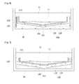
- FIG. 6 is a cross-sectional view of a cooling path in a core catcher having an integrated cooling path according to an embodiment of the present invention
- FIG. 7 is a cross-sectional view of a cooling path in a core catcher having an integrated cooling path according to another embodiment of the present invention.
- Cooling water 32 Operation layer bottom of nuclear reactor building
- Cooling path 103 Downcomer
- Main container 110a Top surface of main container
- Cooling water inflow part 122 Circumferential wall
- FIG. 1 is a schematic cross-sectional view illustrating a state in which a core catcher having an integrated cooling path is installed underneath a lower cavity of a nuclear reactor building below a nuclear reactor pressure container according to the present invention.
- a core catcher 100 having an integrated cooling path according to the present invention is installed underneath a lower cavity defined under a nuclear reactor pressure container 10 so that a molten core material 11 discharged through a damaged part of a nuclear reactor pressure container 10 when a major incident occurs in a nuclear power station is retained and cooled to prevent the molten core material 11 and a pressure-holding structure 20 of a nuclear reactor building from reacting with each other.
- the core catcher 100 has a container shape to collect the molten high-temperature core material 11. To cool the collected molten core material 11, a cooling path 101 in which low-temperature cooling water supplied from a cooling water supply part 30 flows is provided in a bottom surface and side portion of the core catcher 100.
- the cooling water supply part 30 is configured to supply cooling water into the cooling path 10 through a valve 37 installed in a cooling water supply pipe 36 connected to a discharge hole of a refueling water storage tank 35 after water condensed on an operation layer bottom 32 of the nuclear reactor building is stored in an intermediate tank 34 and the refueling water storage tank 35 via a condensed water filter 33.
- FIG. 2 is an exploded perspective view of the core catcher having the integrated cooling path according to the present invention
- FIG. 3 is a coupling perspective view of FIG. 2 .
- the core catcher 100 includes a main container 110 having an inverted roof shape to collect the molten core material 11, a lower structure 120 disposed under and outside the main container 110 to provide the cooling path 101 with a predetermined distance, and supports 130 dispersed between the main container 110 and the lower structure 120.
- the main container 110 has the inverted roof shape in which a surface is inclined upward from a central portion 111 toward both sides. Also, a circumferential wall 112 protrudes upward from each of both edges of the main container 110. Thus, the molten core material 11 discharged through the damaged part of the pressure container 10 may drop onto an inclined top surface 110a of the main container 110, and then be spread to flow toward the central portion 111. As a result, the molten core material 11 may be collected into the central portion 111 of the main container 110.
- the circumferential wall 112 of the main container 110 may serve as a defensive wall so that the molten core material 11 is retained without overflowing out of the main container 110.
- the lower structure 120 has a top surface 120a which is inclined parallel to a bottom surface of the main container 110. Also, a circumferential wall 122 parallel to an outer surface of the circumferential wall 112 of the main container 110 protrudes upward from each of both edges of the lower structure 120.
- the plurality of supports 130 are dispersed with a predetermined distance on the top surface 120a and the circumferential wall 122 of the lower structure 120. Also, the main container 110 is mounted and fixed on the supports 130.
- a cooling water inflow part 121 having a ditch shape is disposed in the inverted roof-shaped central portion of the lower structure 120 in front and rear directions.
- both upwardly inclined surfaces may be symmetrical to each other with respect to the cooling water inflow part 121.
- the integrated cooling path 101 having a piloti structure which has a communicating flow passage and a predetermined height is provided between the main container 110 and the lower structure 120 by the supports 130 dispersed from the central portion up to the edges of the lower structure 120.
- the main container 110 is formed of stainless steel or carbon steel. Also, the main container 110 may be manufactured to satisfy heat transfer performance required for transferring from the molten core material 11 into the integrated cooling path 101, a structural property which endures a load due to the retaining and dropping of the molten core material 11, and corrosion resistant against a boric acid solution injected into the cooling path 101.
- FIG. 4 is a coupling perspective view illustrating a state in which an overflow prevention plate is additionally disposed on the main container of FIG. 3 according to an embodiment of the present invention.
- An overflow prevention plate 115 for retaining the molten core material 11 without overflowing out of the main container 110 may be additionally provided on an upper portion of each of both circumferential walls 112 of the main container 110.
- the overflow prevention plate 115 may be inclined at a predetermined angle with respect to a vertical line toward the central portion of the main container 110 on the upper portion of each of both circumferential walls 112 of the main container 110. Thus, when the major incident in which the molten core material 11 is excessively discharged occurs, it may prevent the molten core material 11 from overflowing out of the main container 110.
- FIG. 5 is a side view illustrating a state in which a heat resistance layer and a protection plate are disposed on a top surface of the main container in the core catcher having the integrated cooling path according to an embodiment of the present invention.
- a heat resistance layer 113 formed of a metallic oxide material such as zirconia, magnesia, and the like may be disposed on the top surface 110a of the main container 110 and an inner surface 112a of the circumferential wall 112.
- the heat resistance layer 113 may protect the main container 110 and the pressure-holding structure 20 of the cooling path 101 while the molten core material 11 is spread and cooled within the main container 110 to stably and continuously cool the molten core material 11.
- a protection plate formed of a metallic material having a high melting point such as tantalum or tungsten may be disposed on the heat resistance layer 113.
- the structural integrity of the core catcher 100 may be maintained.
- the molten core material 110 may be collected within the main container 110 and spread onto the top surface 110a and the circumferential inner surface 112a of the main container inclined in the inverted roof shape.
- the heat transfer performance may be increased by the above-described inclined surface to improve heat transfer efficiency at an upper portion of the molten core material 11 and effectively cool the molten core material 11 through the cooling path 101 disposed under the main container 110.
- FIG. 6 is a cross-sectional view of a cooling path in a core catcher having an integrated cooling path according to an embodiment of the present invention.
- cooling water is injected from the cooling water supply part 30 into the cooling water inflow part 121.
- the cooling path 101 is configured to perform a co-current natural circulation in which cooling water passes through a space between the main container 110 and the lower structure 120 which are bilaterally inclined upward from the cooling water inflow part 121 and passes through an upper space between the circumferential wall 112 of the main container 110 and the circumferential wall 122 of the lower structure 120, and then, the cooling water is moved downward through a downcomer 103 within a space between an outer surface of the lower structure 120 and an inner surface of the pressure-holding structure 20 to return into the cooling water inflow part 121.
- a distance between the main container 110 and the lower structure 120 may be defined by installing the supports 130. Also, a distance between the lower structure 120 and the pressure-holding structure 20 may be defined by installing separate supports (not shown).
- the cooling path 101 has an inclined angle of about 5° to about 20° in an edge direction from a central portion with respect to a horizontal line.
- CHF critical heat flux
- the cooling water When the cooling water is injected, the cooling water is injected through the cooling water inflow part 121. Then, the cooling water and the molten core material 11 are heat-exchanged with the main container 110 therebetween to gradually decrease a temperature of the molten high-temperature core material 11.
- cooling water While the cooling water is continuously circulated along the cooling path 101, a portion of the cooling water 31 moved upward from both sides of the core catcher 100 may be circulated again along the downcomer 103, and the remaining cooling water 31 may be supplied into the main container 110 to directly contact the molten core material 11 and fill the upper portion of the molten core material 11.
- the cooling water passing through the cooling path 101 inclined between the main container 110 and the lower structure 120 is increased in temperature and decreased in density by the heat exchange with the molten core material 11 to flow upward along the inclined surface, the cooling water may be naturally and continuously circulated to realize the co-current natural circulation between bubbles and cooling water 31, thereby continuously cooling the molten core material 11.
- FIG. 7 is a cross-sectional view of a cooling path in a core catcher having an integrated cooling path according to another embodiment of the present invention.
- a cooling path according to another embodiment of the present invention is configured to perform counter-current natural circulation in which cooling water flows along a space between a main container 110 and a lower structure 120 which are bilaterally inclined upward from a cooling water inflow part 121 and an upper space between a circumferential wall 112 of the main container 110 and a circumferential wall 122 of a lower structure 120.
- the cooling path 102 is different from the cooling path 101 only in that bottom and side surfaces of the lower structure 120 are closely attached to a pressure-holding structure 20 without providing the downcomer 103 connected from the upper portion of each of both sides of the core catcher 100 to the lower central portion and in that the supports of the cooling path 102 are disposed at relatively higher positions to perform the counter-current flow within the integrated cooling path 102.
- the cooling water 31 absorbing heat through heat exchange with a molten core material 11 may be moved upward and filled into the main container 110.
- the cooling water 31 having a relatively low temperature and filled within the main container 110 may flow from the circumferential wall 122 toward a lower central portion of the main container 110 along an inclined surface of the lower structure 120 to perform the counter-current natural circulation of the bubble and cooling water again, thereby continuously cooling the molten core material.
- the molten core material 11 may be more widely spread when the molten core material 11 drops, and the cooling path may be increased in sectional area.
- the CHF may be increased to improve the cooling efficiency, and the main container 110, the lower structure 120, and the supports 130 may be simply coupled to each other, thereby easily manufacturing and installing the core catcher 100.
Landscapes
- Physics & Mathematics (AREA)
- Engineering & Computer Science (AREA)
- Plasma & Fusion (AREA)
- General Engineering & Computer Science (AREA)
- High Energy & Nuclear Physics (AREA)
- Structure Of Emergency Protection For Nuclear Reactors (AREA)
Abstract
Description
- The present invention relates to a core catcher having an integrated cooling path, and more particularly, to a core catcher having an integrated cooling path which is capable of effectively collecting, retaining, and cooling a molten high-temperature core material discharged through a damaged part of a nuclear reactor pressure container during a major incident in a nuclear power station to prevent a pressure-holding structure of a nuclear reactor building from being eroded by interacting with the molten core material, thereby maintaining the integrity of the nuclear reactor building.
- In spite of very rare potential outbreak, if a major incident occurs in a nuclear power station, a molten core material may be discharged into a lower cavity of a nuclear reactor through a damaged part of a nuclear reactor pressure container. Here, the molten core material represents a molten high-temperature material in which enriched uranium, which is a nuclear fuel, of a core of the nuclear reactor installed within the nuclear reactor pressure container, zirconium used as a covering material, and a plurality of materials within the nuclear reactor pressure container are mixed with each other.
- The molten core material may generate heat due to decay of a fission product therein. A level of decay heat may be gradually decreased as a time elapses after the nuclear reactor is stopped in operation. When one hour elapses after the operation of the nuclear reactor is stopped, the level of the decay heat may correspond to about 1% of a rated heat output of the nuclear reactor. Thus, if a molten core material discharged when a major incident occurs in a nuclear power station is not adequately cooled, the molten core material may react with concrete on the bottom of a lower cavity of a nuclear reactor building to melt and erode the bottom while generating a large amount of noncondensable gas. As a result, a pressure-holding structure of the nuclear reactor building may be damaged to leak a radioactive matter to the outside, thereby causing serious environmental contamination.
- To cope with a loss of the integrity of the nuclear reactor building when the major incident occurs in the nuclear power station as described above, various countermeasures for retaining and cooling the molten core material to prevent the molten core material from directly reacting with the bottom of the lower cavity of the nuclear reactor are being prepared. A core catcher for collecting and retaining a molten core material and cooling the molten core material through supplying of cooling water in the lower cavity of the nuclear reactor building may be used as representative equipment.
- AREVA EPR and GE ESBWR technologies may be applied to the core catcher developed into a method in which a cooling path is installed underneath a lower portion of a container for collecting a molten core material according to a related art to cool the molten core material.
- The AREVA EPR core catcher is constituted by a pre-catcher for collecting the molten core material, a molten core material transfer channel, and a space in which the molten core material is spread and cooled. The AREVA EPR core catcher has a horizontal type cooling path. That is, the AREVA EPR core catcher has a square cooling channel shape in which the cooling path is separated by a structure which supports the container for retaining and spreading the molten core material.
- The GE ESBWR core catcher has a structure in which a hopper-shaped container for collecting, retaining, and cooling the molten core material is installed underneath a direct lower portion of a nuclear reactor. The GE ESBWR core catcher has an inclined pipe-shaped cooling path. That is, the GE ESBWR core catcher has a circular cooling channel shape in which a radially inclined pipe is installed underneath a lower portion of a container for retaining and spreading a molten core material to separate the cooling path.
- However, since the core catcher according to the related art includes the cooling path having the cooling channel shape separated from each other, the cooling path may have a relatively less sectional area and large flow resistance. Therefore, a time for cooling the molten high-temperature core material may be delayed, and thus, it may be difficult to quickly cope with the incident.
- Embodiments of the present invention are directed to provide a core catcher having an integrated cooling path, which has a structure capable of effectively collecting, retaining, and cooling a molten core material discharged through a damaged part of a nuclear reactor pressure container during a major incident in a nuclear power station.
- Embodiments of the present invention provide a core catcher having an integrated cooling path, which is installed under a nuclear reactor pressure container to retain and cool a molten core material discharged through a damaged part of the nuclear reactor pressure container, thereby preventing interaction between the molten core material and a pressure-holding structure of a nuclear reactor building during a major incident in a nuclear power station, the core catcher including: a main container having an inverted roof shape, the main container being installed under the nuclear reactor pressure container to collect the molten core material; and a lower structure disposed under and outside the main container with dispersed supports therebetween to provide a cooling path having a predetermined distance, thereby removing heat of the molten core material.
- According to the core catcher having the integrated cooling path, since the molten core material is spread on the top surface of the main container having the inverted roof shape, the upper heat transfer area of the molten core material may be increased, and the heat transfer area of the cooling path disposed under the main container may be increased to improve the cooling performance.
- Also, according to the present invention, since the integrated cooling path having the piloti structure in which the supports are dispersed from the central portion to the edge portions so that the cooling path disposed under the main container is disposed at a predetermined height is provided, the cooling path may be increased in sectional area and decreased in flow resistance to more improve the cooling performance when compared to the cooling path, which is separated by a circular pipe or square channel, according to the related art.
- Also, according to the present invention, since the cooling path has the inclined angle of about 5° to about 20° in an edge direction from the central portion with respect to the horizontal line, the CHF may be increased to improve the heat removal performance when compared to the horizontal type cooling path.
- Also, according to the present invention, since the heat resistance layer formed of the metallic oxide material such as zirconia, magnesia, and the like is disposed on the top surface of the main container and the inner surface of the circumferential wall, the heat resistance layer may protect the main container and the press-holding structure from the molten core material while the molten core material is spread and cooled within the main container to stably and continuously cool the molten core material.
- Also, according to the present invention, to prevent the heat resistance layer and the main container from being eroded when the molten core material is jet-discharged through the damaged part of the nuclear reactor pressure container, the protection plate formed of a metallic material having a high melting point such as tantalum or tungsten may be disposed on the heat resistance layer to maintain the structural integrity of the core catcher.
-
FIG. 1 is a schematic cross-sectional view illustrating a state in which a core catcher having an integrated cooling path is installed underneath a lower cavity of a nuclear reactor building below a nuclear reactor pressure container according to the present invention, -
FIG. 2 is an exploded perspective view of the core catcher having the integrated cooling path according to the present invention, -
FIG. 3 is a coupling perspective view ofFIG. 2 , -
FIG. 4 is a coupling perspective view illustrating a state in which an overflow prevention plate is additionally disposed on the main container ofFIG. 3 according to an embodiment of the present invention, -
FIG. 5 is a side view illustrating a state in which a heat resistance layer and a protection plate are disposed on a top surface of the main container in the core catcher having the integrated cooling path according to an embodiment of the present invention, -
FIG. 6 is a cross-sectional view of a cooling path in a core catcher having an integrated cooling path according to an embodiment of the present invention, -
FIG. 7 is a cross-sectional view of a cooling path in a core catcher having an integrated cooling path according to another embodiment of the present invention. - <DESCRIPTION OF REFERENCE NUMERALS>
- 10: Nuclear reactor pressure container 11: Molten core material
- 20: Pressure-holding structure 30: Cooling water supply part
- 31: Cooling water 32: Operation layer bottom of nuclear reactor building
- 33: Condensed water filter 34: Intermediate storage tank
- 35: Refueling water storage tank 36: Cooling water supply pipe
- 37: Valve 100: Core catcher
- 101,102: Cooling path 103: Downcomer
- 110:
Main container 110a: Top surface of main container - 111: Central portion of main container 112: Circumferential wall
- 112a: Circumferential inner surface 113: Heat resistance layer
- 114: Protection plate 115: Overflow prevention plate
- 120:
Lower structure 120a: Top surface of lower structure - 121: Cooling water inflow part 122: Circumferential wall
- 130: Support
- Hereinafter, exemplary embodiments of the present invention will be described in detail with reference to the accompanying drawings.
-
FIG. 1 is a schematic cross-sectional view illustrating a state in which a core catcher having an integrated cooling path is installed underneath a lower cavity of a nuclear reactor building below a nuclear reactor pressure container according to the present invention. - A
core catcher 100 having an integrated cooling path according to the present invention is installed underneath a lower cavity defined under a nuclearreactor pressure container 10 so that amolten core material 11 discharged through a damaged part of a nuclearreactor pressure container 10 when a major incident occurs in a nuclear power station is retained and cooled to prevent themolten core material 11 and a pressure-holding structure 20 of a nuclear reactor building from reacting with each other. - The
core catcher 100 has a container shape to collect the molten high-temperature core material 11. To cool the collectedmolten core material 11, acooling path 101 in which low-temperature cooling water supplied from a coolingwater supply part 30 flows is provided in a bottom surface and side portion of thecore catcher 100. - The cooling
water supply part 30 is configured to supply cooling water into thecooling path 10 through avalve 37 installed in a coolingwater supply pipe 36 connected to a discharge hole of a refuelingwater storage tank 35 after water condensed on anoperation layer bottom 32 of the nuclear reactor building is stored in anintermediate tank 34 and the refuelingwater storage tank 35 via a condensedwater filter 33. - Hereinafter, a detailed structure and operation of the
core catcher 100 schematically shown inFIG. 1 will be described. -
FIG. 2 is an exploded perspective view of the core catcher having the integrated cooling path according to the present invention, andFIG. 3 is a coupling perspective view ofFIG. 2 . - The
core catcher 100 according to the present invention includes amain container 110 having an inverted roof shape to collect themolten core material 11, alower structure 120 disposed under and outside themain container 110 to provide thecooling path 101 with a predetermined distance, and supports 130 dispersed between themain container 110 and thelower structure 120. - The
main container 110 has the inverted roof shape in which a surface is inclined upward from acentral portion 111 toward both sides. Also, acircumferential wall 112 protrudes upward from each of both edges of themain container 110. Thus, themolten core material 11 discharged through the damaged part of thepressure container 10 may drop onto an inclinedtop surface 110a of themain container 110, and then be spread to flow toward thecentral portion 111. As a result, themolten core material 11 may be collected into thecentral portion 111 of themain container 110. - Here, the
circumferential wall 112 of themain container 110 may serve as a defensive wall so that themolten core material 11 is retained without overflowing out of themain container 110. - The
lower structure 120 has atop surface 120a which is inclined parallel to a bottom surface of themain container 110. Also, acircumferential wall 122 parallel to an outer surface of thecircumferential wall 112 of themain container 110 protrudes upward from each of both edges of thelower structure 120. - Also, the plurality of
supports 130 are dispersed with a predetermined distance on thetop surface 120a and thecircumferential wall 122 of thelower structure 120. Also, themain container 110 is mounted and fixed on thesupports 130. - Also, a cooling
water inflow part 121 having a ditch shape is disposed in the inverted roof-shaped central portion of thelower structure 120 in front and rear directions. Here, both upwardly inclined surfaces may be symmetrical to each other with respect to the coolingwater inflow part 121. - Referring to
FIG. 3 , when themain container 110 is coupled to thelower structure 120, the integratedcooling path 101 having a piloti structure which has a communicating flow passage and a predetermined height is provided between themain container 110 and thelower structure 120 by thesupports 130 dispersed from the central portion up to the edges of thelower structure 120. - The
main container 110 is formed of stainless steel or carbon steel. Also, themain container 110 may be manufactured to satisfy heat transfer performance required for transferring from themolten core material 11 into the integratedcooling path 101, a structural property which endures a load due to the retaining and dropping of themolten core material 11, and corrosion resistant against a boric acid solution injected into thecooling path 101. -
FIG. 4 is a coupling perspective view illustrating a state in which an overflow prevention plate is additionally disposed on the main container ofFIG. 3 according to an embodiment of the present invention. - An
overflow prevention plate 115 for retaining themolten core material 11 without overflowing out of themain container 110 may be additionally provided on an upper portion of each of bothcircumferential walls 112 of themain container 110. - The
overflow prevention plate 115 may be inclined at a predetermined angle with respect to a vertical line toward the central portion of themain container 110 on the upper portion of each of bothcircumferential walls 112 of themain container 110. Thus, when the major incident in which themolten core material 11 is excessively discharged occurs, it may prevent themolten core material 11 from overflowing out of themain container 110. -
FIG. 5 is a side view illustrating a state in which a heat resistance layer and a protection plate are disposed on a top surface of the main container in the core catcher having the integrated cooling path according to an embodiment of the present invention. - A
heat resistance layer 113 formed of a metallic oxide material such as zirconia, magnesia, and the like may be disposed on thetop surface 110a of themain container 110 and aninner surface 112a of thecircumferential wall 112. Thus, theheat resistance layer 113 may protect themain container 110 and the pressure-holdingstructure 20 of thecooling path 101 while themolten core material 11 is spread and cooled within themain container 110 to stably and continuously cool themolten core material 11. - Also, to prevent the
heat resistance layer 113 and themain container 110 from being eroded when themolten core material 11 is jet-discharged through the damaged part of the nuclearreactor pressure container 10, a protection plate formed of a metallic material having a high melting point such as tantalum or tungsten may be disposed on theheat resistance layer 113. Thus, the structural integrity of thecore catcher 100 may be maintained. - As described above, when the
molten core material 11 drops into thecore catcher 100, themolten core material 110 may be collected within themain container 110 and spread onto thetop surface 110a and the circumferentialinner surface 112a of the main container inclined in the inverted roof shape. Thus, the heat transfer performance may be increased by the above-described inclined surface to improve heat transfer efficiency at an upper portion of themolten core material 11 and effectively cool themolten core material 11 through thecooling path 101 disposed under themain container 110. - Hereinafter, a cooling effect of the
molten core material 11 in thecore catcher 100 according to the present invention will be described. -
FIG. 6 is a cross-sectional view of a cooling path in a core catcher having an integrated cooling path according to an embodiment of the present invention. - After the
molten core material 11 is spread within themain container 110, cooling water is injected from the coolingwater supply part 30 into the coolingwater inflow part 121. - The
cooling path 101 according to an embodiment of the present invention is configured to perform a co-current natural circulation in which cooling water passes through a space between themain container 110 and thelower structure 120 which are bilaterally inclined upward from the coolingwater inflow part 121 and passes through an upper space between thecircumferential wall 112 of themain container 110 and thecircumferential wall 122 of thelower structure 120, and then, the cooling water is moved downward through adowncomer 103 within a space between an outer surface of thelower structure 120 and an inner surface of the pressure-holdingstructure 20 to return into the coolingwater inflow part 121. - Here, a distance between the
main container 110 and thelower structure 120 may be defined by installing thesupports 130. Also, a distance between thelower structure 120 and the pressure-holdingstructure 20 may be defined by installing separate supports (not shown). - The
cooling path 101 according to the current embodiment has an inclined angle of about 5° to about 20° in an edge direction from a central portion with respect to a horizontal line. Thus, as a critical heat flux (CHF) is increased, heat removal performance may be improved when compared to that of a horizontal type cooling path. - When the cooling water is injected, the cooling water is injected through the cooling
water inflow part 121. Then, the cooling water and themolten core material 11 are heat-exchanged with themain container 110 therebetween to gradually decrease a temperature of the molten high-temperature core material 11. - While the cooling water is continuously circulated along the
cooling path 101, a portion of the coolingwater 31 moved upward from both sides of thecore catcher 100 may be circulated again along thedowncomer 103, and the remainingcooling water 31 may be supplied into themain container 110 to directly contact themolten core material 11 and fill the upper portion of themolten core material 11. - Since the cooling water passing through the
cooling path 101 inclined between themain container 110 and thelower structure 120 is increased in temperature and decreased in density by the heat exchange with themolten core material 11 to flow upward along the inclined surface, the cooling water may be naturally and continuously circulated to realize the co-current natural circulation between bubbles and coolingwater 31, thereby continuously cooling themolten core material 11. -
FIG. 7 is a cross-sectional view of a cooling path in a core catcher having an integrated cooling path according to another embodiment of the present invention. - A cooling path according to another embodiment of the present invention is configured to perform counter-current natural circulation in which cooling water flows along a space between a
main container 110 and alower structure 120 which are bilaterally inclined upward from a coolingwater inflow part 121 and an upper space between acircumferential wall 112 of themain container 110 and acircumferential wall 122 of alower structure 120. - When compared to the
cooling path 101 ofFIG. 6 , thecooling path 102 according to the current embodiment is different from thecooling path 101 only in that bottom and side surfaces of thelower structure 120 are closely attached to a pressure-holdingstructure 20 without providing thedowncomer 103 connected from the upper portion of each of both sides of thecore catcher 100 to the lower central portion and in that the supports of thecooling path 102 are disposed at relatively higher positions to perform the counter-current flow within the integratedcooling path 102. - After the cooling water is injected, bubbles and cooling
water 31 flow from the coolingwater inflow part 121 disposed at a lower central portion of themain container 110 towardcircumferential walls main container 110. Thus, the generated bubbles may be discharged toward an upper side of thecore catcher 100, and then, new cooling water may be introduced again. - The cooling
water 31 absorbing heat through heat exchange with amolten core material 11 may be moved upward and filled into themain container 110. The coolingwater 31 having a relatively low temperature and filled within themain container 110 may flow from thecircumferential wall 122 toward a lower central portion of themain container 110 along an inclined surface of thelower structure 120 to perform the counter-current natural circulation of the bubble and cooling water again, thereby continuously cooling the molten core material. - As described above, according to the
core catcher 100 having the integrated cooling path, since the cooling path having the inclined surface in the inverted roof shape, themolten core material 11 may be more widely spread when themolten core material 11 drops, and the cooling path may be increased in sectional area. In addition, the CHF may be increased to improve the cooling efficiency, and themain container 110, thelower structure 120, and thesupports 130 may be simply coupled to each other, thereby easily manufacturing and installing thecore catcher 100. -
Claims (8)
- A core catcher having an integrated cooling path, which is installed under a nuclear reactor pressure container to retain and cool a molten core material discharged through a damaged part of the nuclear reactor pressure container, thereby preventing interaction between the molten core material and a pressure-holding structure of a nuclear reactor building during a major incident in a nuclear power station, the core catcher comprising:a main container having an inverted roof shape, the main container being installed under the nuclear reactor pressure container to collect the molten core material; anda lower structure disposed under and outside the main container with dispersed supports therebetween to provide a cooling path having a predetermined distance, thereby removing heat of the molten core material.
- The core catcher of claim 1, wherein the molten core material is collected and spread on a central inclined surface having the inverted roof shape of the main container, and
a circumference wall is disposed on each of edge portions of the main container to retain the molten core material without overflowing out of the main container. - The core catcher of claim 2, wherein the cooling path contacts a lower inclined surface of the main container and an outer surface of the circumference wall, and
the cooling path has a piloti structure in which the supports are dispersed at a predetermined distance between the main container and the lower structure to provide the integrated cooling path without being separated therein. - The core catcher of claim 3, wherein the cooling path comprises an inclined type cooling path which is parallel to the inclined surface of the main container containing the molten core material.
- The core catcher of claim 2, wherein cooling water is injected into a lower central portion of the main container at an initial time at which the molten core material drops, and
when the cooling water is completely injected, the cooling water passes through the cooling path of the circumferential wall from the central portion of the cooling path to flow through a downcomer connected from an upper portion of the core catcher to the lower central portion of the main container so that bubbles and the cooling water are naturally circulated in a co-current manner, thereby removing heat of the molten core material. - The core catcher of claim 2, wherein cooling water is injected into a lower central portion of the main container at an initial time at which the molten core material drops, and
when the cooling water is completely injected, the cooling water is naturally circulated within the cooling path in a counter-current manner to remove heat of the molten core material. - The core catcher of claim 2, wherein a heat resistance layer is disposed on a top surface of the main container and an inner surface of the circumferential wall, and
a protection plate is disposed on a top surface of the heat resistance layer to prevent the heat resistance layer and the main container from being eroded by the molten core material dropping or jet-discharged through a damaged part of the nuclear reactor pressure container. - The core catcher of claim 2, wherein an overflow prevention plate is additionally disposed on an upper portion of the circumferential wall of each of both sides of the main container to retain the molten core material without overflowing out of the main container.
Applications Claiming Priority (2)
| Application Number | Priority Date | Filing Date | Title |
|---|---|---|---|
| KR1020100056075A KR101005668B1 (en) | 2010-06-14 | 2010-06-14 | Core catcher with integrated cooling flow |
| PCT/KR2010/004076 WO2011158984A1 (en) | 2010-06-14 | 2010-06-23 | Core catcher having an integrated cooling path |
Publications (3)
| Publication Number | Publication Date |
|---|---|
| EP2581913A1 true EP2581913A1 (en) | 2013-04-17 |
| EP2581913A4 EP2581913A4 (en) | 2017-04-26 |
| EP2581913B1 EP2581913B1 (en) | 2020-01-01 |
Family
ID=43615770
Family Applications (1)
| Application Number | Title | Priority Date | Filing Date |
|---|---|---|---|
| EP10853285.4A Active EP2581913B1 (en) | 2010-06-14 | 2010-06-23 | Core catcher having an integrated cooling path |
Country Status (4)
| Country | Link |
|---|---|
| EP (1) | EP2581913B1 (en) |
| KR (1) | KR101005668B1 (en) |
| CN (1) | CN103081023B (en) |
| WO (1) | WO2011158984A1 (en) |
Cited By (2)
| Publication number | Priority date | Publication date | Assignee | Title |
|---|---|---|---|---|
| WO2017176158A1 (en) * | 2016-04-04 | 2017-10-12 | Константин Иванович ГОЛОВКО | Reactor containment system with a core catcher |
| EP3567607A4 (en) * | 2017-01-03 | 2020-06-10 | Korea Hydro & Nuclear Power Co., Ltd | PASSIVE CONTROLLED CORIUM COOLING APPARATUS |
Families Citing this family (16)
| Publication number | Priority date | Publication date | Assignee | Title |
|---|---|---|---|---|
| CN103177778A (en) * | 2013-01-08 | 2013-06-26 | 上海核工程研究设计院 | Large-scale passive nuclear plant reactor core catcher with bottom water injection and external cooling |
| CN103165198A (en) * | 2013-01-08 | 2013-06-19 | 上海核工程研究设计院 | Large-scale passive pressurized water reactor nuclear power plant reactor core catcher with melt expansion room |
| KR101585841B1 (en) * | 2014-10-20 | 2016-01-15 | 한국수력원자력 주식회사 | Core catcher having enhanced core cooling performance |
| RU2576516C1 (en) * | 2014-12-16 | 2016-03-10 | Акционерное Общество "Атомэнергопроект" | System of localisation and cooling of melt of active zone of pressurised water reactor |
| CN105551541B (en) * | 2015-12-16 | 2020-06-23 | 中国核电工程有限公司 | A core melt grouped capture and cooling system |
| CN105609146B (en) * | 2015-12-25 | 2019-10-29 | 中国核电工程有限公司 | A kind of reactor core fusant trap |
| WO2018062918A1 (en) * | 2016-09-28 | 2018-04-05 | 한국수력원자력 주식회사 | Stepped core catcher having enhanced core spreading performance |
| RU2700925C1 (en) * | 2018-09-25 | 2019-09-24 | Акционерное Общество "Атомэнергопроект" | Nuclear reactor core melt localization device |
| KR20220111563A (en) * | 2021-02-02 | 2022-08-09 | 한국수력원자력 주식회사 | Core catcher |
| KR102501198B1 (en) * | 2021-08-18 | 2023-02-21 | 한국원자력연구원 | Core-catcher with improved stability of cooling performance |
| KR102510484B1 (en) * | 2021-11-09 | 2023-03-14 | 한국수력원자력 주식회사 | Core catcher system |
| KR102510486B1 (en) * | 2021-11-09 | 2023-03-14 | 한국수력원자력 주식회사 | Core catcher system |
| KR102510478B1 (en) * | 2021-11-09 | 2023-03-14 | 한국수력원자력 주식회사 | Core catcher system |
| KR20250106990A (en) | 2024-01-04 | 2025-07-11 | 한국수력원자력 주식회사 | Core catcher |
| CN118094364B (en) * | 2024-02-27 | 2025-03-18 | 阳江核电有限公司 | A method for evaluating reactor core quadrant power tilt state |
| KR102897993B1 (en) | 2024-04-08 | 2025-12-08 | 한국수력원자력 주식회사 | Core catcher |
Family Cites Families (4)
| Publication number | Priority date | Publication date | Assignee | Title |
|---|---|---|---|---|
| US7558360B1 (en) * | 2003-12-31 | 2009-07-07 | General Electric Company | Core catcher cooling |
| JP4612558B2 (en) * | 2006-02-22 | 2011-01-12 | 株式会社東芝 | Core catcher and reactor containment |
| EP1988551B1 (en) * | 2006-02-22 | 2015-01-28 | Kabushiki Kaisha Toshiba | Core catcher |
| JP4987681B2 (en) * | 2007-12-12 | 2012-07-25 | 株式会社東芝 | Primary containment vessel and leak detection floor |
-
2010
- 2010-06-14 KR KR1020100056075A patent/KR101005668B1/en active Active
- 2010-06-23 EP EP10853285.4A patent/EP2581913B1/en active Active
- 2010-06-23 WO PCT/KR2010/004076 patent/WO2011158984A1/en not_active Ceased
- 2010-06-23 CN CN201080068588.4A patent/CN103081023B/en active Active
Non-Patent Citations (1)
| Title |
|---|
| See references of WO2011158984A1 * |
Cited By (2)
| Publication number | Priority date | Publication date | Assignee | Title |
|---|---|---|---|---|
| WO2017176158A1 (en) * | 2016-04-04 | 2017-10-12 | Константин Иванович ГОЛОВКО | Reactor containment system with a core catcher |
| EP3567607A4 (en) * | 2017-01-03 | 2020-06-10 | Korea Hydro & Nuclear Power Co., Ltd | PASSIVE CONTROLLED CORIUM COOLING APPARATUS |
Also Published As
| Publication number | Publication date |
|---|---|
| EP2581913A4 (en) | 2017-04-26 |
| WO2011158984A1 (en) | 2011-12-22 |
| EP2581913B1 (en) | 2020-01-01 |
| CN103081023A (en) | 2013-05-01 |
| CN103081023B (en) | 2015-10-21 |
| KR101005668B1 (en) | 2011-01-05 |
Similar Documents
| Publication | Publication Date | Title |
|---|---|---|
| EP2581913B1 (en) | Core catcher having an integrated cooling path | |
| JP4612558B2 (en) | Core catcher and reactor containment | |
| US8358732B2 (en) | Core catcher, manufacturing method thereof, reactor containment vessel and manufacturing method thereof | |
| EP3166114B1 (en) | Passive containment cooling and filtered venting system for a nuclear power plant | |
| CN110459333B (en) | Double-layer crucible reactor core melt trapping device with internal cooling pipe | |
| US20120051485A1 (en) | Corium cooling promoting apparatus and containment | |
| CN109102906B (en) | Reactor core catcher system based on built-in refueling water tank | |
| JP4620449B2 (en) | Core catcher cooling assembly and nuclear reactor having the assembly | |
| CN106663479A (en) | Porous cooling block for cooling molten core and molten-core cooling apparatus including same, and molten-core cooling method using same | |
| EP3255637B1 (en) | Core catcher and boiling water nuclear plant using the same | |
| CN108053895B (en) | A reactor core melt capture device with sub-package enhanced cooling | |
| JP2009257918A (en) | Core melt cooling system | |
| JP2010038571A (en) | Furnace-core melted product cooling device and furnace-core melted product cooling method | |
| JP2012032276A (en) | Corium cooling device and storage vessel | |
| KR20050080668A (en) | Cooling device of molten core penetrating a reactor vessel and the process | |
| JP2014157029A (en) | Nuclear reactor system and nuclear reactor molten material retaining device | |
| JP2013108772A (en) | Melt collector | |
| CN203070782U (en) | Crucible type reactor core catcher for large-size non-dynamic pressurized water reactor nuclear power plant | |
| JP2017203757A (en) | Primary containment vessel | |
| JP7051338B2 (en) | Core melt holding structure and reactor containment vessel | |
| JP6590492B2 (en) | Reactor containment vessel and method for constructing reactor containment vessel | |
| KR101787410B1 (en) | Core Catcher with a Cooling Circulation | |
| KR102791622B1 (en) | Core catcher with improved cooling performance | |
| Lee et al. | Corium Retention and Cooling by an Ex-vessel Core-catcher for Nuclear Power Plants | |
| Journeau | Chapter XIV Ex-Vessel Corium Retention Concepts |
Legal Events
| Date | Code | Title | Description |
|---|---|---|---|
| PUAI | Public reference made under article 153(3) epc to a published international application that has entered the european phase |
Free format text: ORIGINAL CODE: 0009012 |
|
| 17P | Request for examination filed |
Effective date: 20130107 |
|
| AK | Designated contracting states |
Kind code of ref document: A1 Designated state(s): AL AT BE BG CH CY CZ DE DK EE ES FI FR GB GR HR HU IE IS IT LI LT LU LV MC MK MT NL NO PL PT RO SE SI SK SM TR |
|
| DAX | Request for extension of the european patent (deleted) | ||
| REG | Reference to a national code |
Ref country code: DE Ref legal event code: R079 Ref document number: 602010062663 Country of ref document: DE Free format text: PREVIOUS MAIN CLASS: G21C0015180000 Ipc: G21C0009016000 |
|
| RA4 | Supplementary search report drawn up and despatched (corrected) |
Effective date: 20170324 |
|
| RIC1 | Information provided on ipc code assigned before grant |
Ipc: G21C 9/00 20060101ALI20170320BHEP Ipc: G21C 9/016 20060101AFI20170320BHEP Ipc: G21C 15/18 20060101ALI20170320BHEP |
|
| GRAP | Despatch of communication of intention to grant a patent |
Free format text: ORIGINAL CODE: EPIDOSNIGR1 |
|
| STAA | Information on the status of an ep patent application or granted ep patent |
Free format text: STATUS: GRANT OF PATENT IS INTENDED |
|
| INTG | Intention to grant announced |
Effective date: 20190403 |
|
| GRAS | Grant fee paid |
Free format text: ORIGINAL CODE: EPIDOSNIGR3 |
|
| GRAA | (expected) grant |
Free format text: ORIGINAL CODE: 0009210 |
|
| STAA | Information on the status of an ep patent application or granted ep patent |
Free format text: STATUS: THE PATENT HAS BEEN GRANTED |
|
| AK | Designated contracting states |
Kind code of ref document: B1 Designated state(s): AL AT BE BG CH CY CZ DE DK EE ES FI FR GB GR HR HU IE IS IT LI LT LU LV MC MK MT NL NO PL PT RO SE SI SK SM TR |
|
| REG | Reference to a national code |
Ref country code: GB Ref legal event code: FG4D |
|
| REG | Reference to a national code |
Ref country code: CH Ref legal event code: EP Ref country code: AT Ref legal event code: REF Ref document number: 1220816 Country of ref document: AT Kind code of ref document: T Effective date: 20200115 |
|
| REG | Reference to a national code |
Ref country code: IE Ref legal event code: FG4D |
|
| REG | Reference to a national code |
Ref country code: DE Ref legal event code: R096 Ref document number: 602010062663 Country of ref document: DE |
|
| REG | Reference to a national code |
Ref country code: NL Ref legal event code: MP Effective date: 20200101 |
|
| REG | Reference to a national code |
Ref country code: LT Ref legal event code: MG4D |
|
| PG25 | Lapsed in a contracting state [announced via postgrant information from national office to epo] |
Ref country code: NO Free format text: LAPSE BECAUSE OF FAILURE TO SUBMIT A TRANSLATION OF THE DESCRIPTION OR TO PAY THE FEE WITHIN THE PRESCRIBED TIME-LIMIT Effective date: 20200401 Ref country code: FI Free format text: LAPSE BECAUSE OF FAILURE TO SUBMIT A TRANSLATION OF THE DESCRIPTION OR TO PAY THE FEE WITHIN THE PRESCRIBED TIME-LIMIT Effective date: 20200101 Ref country code: PT Free format text: LAPSE BECAUSE OF FAILURE TO SUBMIT A TRANSLATION OF THE DESCRIPTION OR TO PAY THE FEE WITHIN THE PRESCRIBED TIME-LIMIT Effective date: 20200527 Ref country code: LT Free format text: LAPSE BECAUSE OF FAILURE TO SUBMIT A TRANSLATION OF THE DESCRIPTION OR TO PAY THE FEE WITHIN THE PRESCRIBED TIME-LIMIT Effective date: 20200101 Ref country code: NL Free format text: LAPSE BECAUSE OF FAILURE TO SUBMIT A TRANSLATION OF THE DESCRIPTION OR TO PAY THE FEE WITHIN THE PRESCRIBED TIME-LIMIT Effective date: 20200101 |
|
| PG25 | Lapsed in a contracting state [announced via postgrant information from national office to epo] |
Ref country code: BG Free format text: LAPSE BECAUSE OF FAILURE TO SUBMIT A TRANSLATION OF THE DESCRIPTION OR TO PAY THE FEE WITHIN THE PRESCRIBED TIME-LIMIT Effective date: 20200401 Ref country code: SE Free format text: LAPSE BECAUSE OF FAILURE TO SUBMIT A TRANSLATION OF THE DESCRIPTION OR TO PAY THE FEE WITHIN THE PRESCRIBED TIME-LIMIT Effective date: 20200101 Ref country code: IS Free format text: LAPSE BECAUSE OF FAILURE TO SUBMIT A TRANSLATION OF THE DESCRIPTION OR TO PAY THE FEE WITHIN THE PRESCRIBED TIME-LIMIT Effective date: 20200501 Ref country code: HR Free format text: LAPSE BECAUSE OF FAILURE TO SUBMIT A TRANSLATION OF THE DESCRIPTION OR TO PAY THE FEE WITHIN THE PRESCRIBED TIME-LIMIT Effective date: 20200101 Ref country code: GR Free format text: LAPSE BECAUSE OF FAILURE TO SUBMIT A TRANSLATION OF THE DESCRIPTION OR TO PAY THE FEE WITHIN THE PRESCRIBED TIME-LIMIT Effective date: 20200402 Ref country code: LV Free format text: LAPSE BECAUSE OF FAILURE TO SUBMIT A TRANSLATION OF THE DESCRIPTION OR TO PAY THE FEE WITHIN THE PRESCRIBED TIME-LIMIT Effective date: 20200101 |
|
| REG | Reference to a national code |
Ref country code: DE Ref legal event code: R097 Ref document number: 602010062663 Country of ref document: DE |
|
| PG25 | Lapsed in a contracting state [announced via postgrant information from national office to epo] |
Ref country code: RO Free format text: LAPSE BECAUSE OF FAILURE TO SUBMIT A TRANSLATION OF THE DESCRIPTION OR TO PAY THE FEE WITHIN THE PRESCRIBED TIME-LIMIT Effective date: 20200101 Ref country code: DK Free format text: LAPSE BECAUSE OF FAILURE TO SUBMIT A TRANSLATION OF THE DESCRIPTION OR TO PAY THE FEE WITHIN THE PRESCRIBED TIME-LIMIT Effective date: 20200101 Ref country code: EE Free format text: LAPSE BECAUSE OF FAILURE TO SUBMIT A TRANSLATION OF THE DESCRIPTION OR TO PAY THE FEE WITHIN THE PRESCRIBED TIME-LIMIT Effective date: 20200101 Ref country code: SM Free format text: LAPSE BECAUSE OF FAILURE TO SUBMIT A TRANSLATION OF THE DESCRIPTION OR TO PAY THE FEE WITHIN THE PRESCRIBED TIME-LIMIT Effective date: 20200101 Ref country code: SK Free format text: LAPSE BECAUSE OF FAILURE TO SUBMIT A TRANSLATION OF THE DESCRIPTION OR TO PAY THE FEE WITHIN THE PRESCRIBED TIME-LIMIT Effective date: 20200101 Ref country code: ES Free format text: LAPSE BECAUSE OF FAILURE TO SUBMIT A TRANSLATION OF THE DESCRIPTION OR TO PAY THE FEE WITHIN THE PRESCRIBED TIME-LIMIT Effective date: 20200101 |
|
| PLBE | No opposition filed within time limit |
Free format text: ORIGINAL CODE: 0009261 |
|
| STAA | Information on the status of an ep patent application or granted ep patent |
Free format text: STATUS: NO OPPOSITION FILED WITHIN TIME LIMIT |
|
| REG | Reference to a national code |
Ref country code: AT Ref legal event code: MK05 Ref document number: 1220816 Country of ref document: AT Kind code of ref document: T Effective date: 20200101 |
|
| 26N | No opposition filed |
Effective date: 20201002 |
|
| REG | Reference to a national code |
Ref country code: DE Ref legal event code: R119 Ref document number: 602010062663 Country of ref document: DE |
|
| PG25 | Lapsed in a contracting state [announced via postgrant information from national office to epo] |
Ref country code: IT Free format text: LAPSE BECAUSE OF FAILURE TO SUBMIT A TRANSLATION OF THE DESCRIPTION OR TO PAY THE FEE WITHIN THE PRESCRIBED TIME-LIMIT Effective date: 20200101 Ref country code: AT Free format text: LAPSE BECAUSE OF FAILURE TO SUBMIT A TRANSLATION OF THE DESCRIPTION OR TO PAY THE FEE WITHIN THE PRESCRIBED TIME-LIMIT Effective date: 20200101 Ref country code: MC Free format text: LAPSE BECAUSE OF FAILURE TO SUBMIT A TRANSLATION OF THE DESCRIPTION OR TO PAY THE FEE WITHIN THE PRESCRIBED TIME-LIMIT Effective date: 20200101 |
|
| REG | Reference to a national code |
Ref country code: CH Ref legal event code: PL |
|
| PG25 | Lapsed in a contracting state [announced via postgrant information from national office to epo] |
Ref country code: PL Free format text: LAPSE BECAUSE OF FAILURE TO SUBMIT A TRANSLATION OF THE DESCRIPTION OR TO PAY THE FEE WITHIN THE PRESCRIBED TIME-LIMIT Effective date: 20200101 Ref country code: SI Free format text: LAPSE BECAUSE OF FAILURE TO SUBMIT A TRANSLATION OF THE DESCRIPTION OR TO PAY THE FEE WITHIN THE PRESCRIBED TIME-LIMIT Effective date: 20200101 |
|
| GBPC | Gb: european patent ceased through non-payment of renewal fee |
Effective date: 20200623 |
|
| PG25 | Lapsed in a contracting state [announced via postgrant information from national office to epo] |
Ref country code: LU Free format text: LAPSE BECAUSE OF NON-PAYMENT OF DUE FEES Effective date: 20200623 |
|
| REG | Reference to a national code |
Ref country code: BE Ref legal event code: MM Effective date: 20200630 |
|
| PG25 | Lapsed in a contracting state [announced via postgrant information from national office to epo] |
Ref country code: GB Free format text: LAPSE BECAUSE OF NON-PAYMENT OF DUE FEES Effective date: 20200623 Ref country code: CH Free format text: LAPSE BECAUSE OF NON-PAYMENT OF DUE FEES Effective date: 20200630 Ref country code: IE Free format text: LAPSE BECAUSE OF NON-PAYMENT OF DUE FEES Effective date: 20200623 Ref country code: LI Free format text: LAPSE BECAUSE OF NON-PAYMENT OF DUE FEES Effective date: 20200630 |
|
| PG25 | Lapsed in a contracting state [announced via postgrant information from national office to epo] |
Ref country code: BE Free format text: LAPSE BECAUSE OF NON-PAYMENT OF DUE FEES Effective date: 20200630 Ref country code: DE Free format text: LAPSE BECAUSE OF NON-PAYMENT OF DUE FEES Effective date: 20210101 |
|
| PG25 | Lapsed in a contracting state [announced via postgrant information from national office to epo] |
Ref country code: TR Free format text: LAPSE BECAUSE OF FAILURE TO SUBMIT A TRANSLATION OF THE DESCRIPTION OR TO PAY THE FEE WITHIN THE PRESCRIBED TIME-LIMIT Effective date: 20200101 Ref country code: MT Free format text: LAPSE BECAUSE OF FAILURE TO SUBMIT A TRANSLATION OF THE DESCRIPTION OR TO PAY THE FEE WITHIN THE PRESCRIBED TIME-LIMIT Effective date: 20200101 Ref country code: CY Free format text: LAPSE BECAUSE OF FAILURE TO SUBMIT A TRANSLATION OF THE DESCRIPTION OR TO PAY THE FEE WITHIN THE PRESCRIBED TIME-LIMIT Effective date: 20200101 |
|
| PG25 | Lapsed in a contracting state [announced via postgrant information from national office to epo] |
Ref country code: MK Free format text: LAPSE BECAUSE OF FAILURE TO SUBMIT A TRANSLATION OF THE DESCRIPTION OR TO PAY THE FEE WITHIN THE PRESCRIBED TIME-LIMIT Effective date: 20200101 Ref country code: AL Free format text: LAPSE BECAUSE OF FAILURE TO SUBMIT A TRANSLATION OF THE DESCRIPTION OR TO PAY THE FEE WITHIN THE PRESCRIBED TIME-LIMIT Effective date: 20200101 |
|
| PGFP | Annual fee paid to national office [announced via postgrant information from national office to epo] |
Ref country code: FR Payment date: 20250502 Year of fee payment: 16 |
|
| PGFP | Annual fee paid to national office [announced via postgrant information from national office to epo] |
Ref country code: CZ Payment date: 20250506 Year of fee payment: 16 |