EP2581690A2 - Cooling system of a refrigerator and suction system for a compressor fluid - Google Patents
Cooling system of a refrigerator and suction system for a compressor fluid Download PDFInfo
- Publication number
- EP2581690A2 EP2581690A2 EP11730872.6A EP11730872A EP2581690A2 EP 2581690 A2 EP2581690 A2 EP 2581690A2 EP 11730872 A EP11730872 A EP 11730872A EP 2581690 A2 EP2581690 A2 EP 2581690A2
- Authority
- EP
- European Patent Office
- Prior art keywords
- compressor
- fluid
- suction
- fact
- valve
- Prior art date
- Legal status (The legal status is an assumption and is not a legal conclusion. Google has not performed a legal analysis and makes no representation as to the accuracy of the status listed.)
- Withdrawn
Links
- 239000012530 fluid Substances 0.000 title claims abstract description 81
- 238000001816 cooling Methods 0.000 title claims abstract description 26
- 239000003507 refrigerant Substances 0.000 claims abstract description 39
- 238000005057 refrigeration Methods 0.000 claims abstract description 17
- 230000006835 compression Effects 0.000 claims description 7
- 238000007906 compression Methods 0.000 claims description 7
- 101001064282 Homo sapiens Platelet-activating factor acetylhydrolase IB subunit beta Proteins 0.000 description 7
- 102100030655 Platelet-activating factor acetylhydrolase IB subunit beta Human genes 0.000 description 7
- 244000045947 parasite Species 0.000 description 5
- 239000003921 oil Substances 0.000 description 4
- 208000036366 Sensation of pressure Diseases 0.000 description 2
- 239000007789 gas Substances 0.000 description 2
- 239000010687 lubricating oil Substances 0.000 description 2
- 238000000034 method Methods 0.000 description 2
- ONPGOSVDVDPBCY-CQSZACIVSA-N 6-amino-5-[(1r)-1-(2,6-dichloro-3-fluorophenyl)ethoxy]-n-[4-(4-methylpiperazine-1-carbonyl)phenyl]pyridazine-3-carboxamide Chemical compound O([C@H](C)C=1C(=C(F)C=CC=1Cl)Cl)C(C(=NN=1)N)=CC=1C(=O)NC(C=C1)=CC=C1C(=O)N1CCN(C)CC1 ONPGOSVDVDPBCY-CQSZACIVSA-N 0.000 description 1
- 239000003990 capacitor Substances 0.000 description 1
- 230000003247 decreasing effect Effects 0.000 description 1
- 230000009977 dual effect Effects 0.000 description 1
- 239000007792 gaseous phase Substances 0.000 description 1
- 239000007791 liquid phase Substances 0.000 description 1
- 230000001050 lubricating effect Effects 0.000 description 1
- 239000012071 phase Substances 0.000 description 1
Images



Classifications
-
- F—MECHANICAL ENGINEERING; LIGHTING; HEATING; WEAPONS; BLASTING
- F04—POSITIVE - DISPLACEMENT MACHINES FOR LIQUIDS; PUMPS FOR LIQUIDS OR ELASTIC FLUIDS
- F04B—POSITIVE-DISPLACEMENT MACHINES FOR LIQUIDS; PUMPS
- F04B39/00—Component parts, details, or accessories, of pumps or pumping systems specially adapted for elastic fluids, not otherwise provided for in, or of interest apart from, groups F04B25/00 - F04B37/00
- F04B39/06—Cooling; Heating; Prevention of freezing
-
- F—MECHANICAL ENGINEERING; LIGHTING; HEATING; WEAPONS; BLASTING
- F04—POSITIVE - DISPLACEMENT MACHINES FOR LIQUIDS; PUMPS FOR LIQUIDS OR ELASTIC FLUIDS
- F04B—POSITIVE-DISPLACEMENT MACHINES FOR LIQUIDS; PUMPS
- F04B39/00—Component parts, details, or accessories, of pumps or pumping systems specially adapted for elastic fluids, not otherwise provided for in, or of interest apart from, groups F04B25/00 - F04B37/00
- F04B39/10—Adaptations or arrangements of distribution members
-
- F—MECHANICAL ENGINEERING; LIGHTING; HEATING; WEAPONS; BLASTING
- F25—REFRIGERATION OR COOLING; COMBINED HEATING AND REFRIGERATION SYSTEMS; HEAT PUMP SYSTEMS; MANUFACTURE OR STORAGE OF ICE; LIQUEFACTION SOLIDIFICATION OF GASES
- F25B—REFRIGERATION MACHINES, PLANTS OR SYSTEMS; COMBINED HEATING AND REFRIGERATION SYSTEMS; HEAT PUMP SYSTEMS
- F25B1/00—Compression machines, plants or systems with non-reversible cycle
- F25B1/005—Compression machines, plants or systems with non-reversible cycle of the single unit type
-
- F—MECHANICAL ENGINEERING; LIGHTING; HEATING; WEAPONS; BLASTING
- F25—REFRIGERATION OR COOLING; COMBINED HEATING AND REFRIGERATION SYSTEMS; HEAT PUMP SYSTEMS; MANUFACTURE OR STORAGE OF ICE; LIQUEFACTION SOLIDIFICATION OF GASES
- F25B—REFRIGERATION MACHINES, PLANTS OR SYSTEMS; COMBINED HEATING AND REFRIGERATION SYSTEMS; HEAT PUMP SYSTEMS
- F25B41/00—Fluid-circulation arrangements
- F25B41/20—Disposition of valves, e.g. of on-off valves or flow control valves
-
- F—MECHANICAL ENGINEERING; LIGHTING; HEATING; WEAPONS; BLASTING
- F25—REFRIGERATION OR COOLING; COMBINED HEATING AND REFRIGERATION SYSTEMS; HEAT PUMP SYSTEMS; MANUFACTURE OR STORAGE OF ICE; LIQUEFACTION SOLIDIFICATION OF GASES
- F25B—REFRIGERATION MACHINES, PLANTS OR SYSTEMS; COMBINED HEATING AND REFRIGERATION SYSTEMS; HEAT PUMP SYSTEMS
- F25B5/00—Compression machines, plants or systems, with several evaporator circuits, e.g. for varying refrigerating capacity
- F25B5/02—Compression machines, plants or systems, with several evaporator circuits, e.g. for varying refrigerating capacity arranged in parallel
-
- F—MECHANICAL ENGINEERING; LIGHTING; HEATING; WEAPONS; BLASTING
- F25—REFRIGERATION OR COOLING; COMBINED HEATING AND REFRIGERATION SYSTEMS; HEAT PUMP SYSTEMS; MANUFACTURE OR STORAGE OF ICE; LIQUEFACTION SOLIDIFICATION OF GASES
- F25D—REFRIGERATORS; COLD ROOMS; ICE-BOXES; COOLING OR FREEZING APPARATUS NOT OTHERWISE PROVIDED FOR
- F25D11/00—Self-contained movable devices, e.g. domestic refrigerators
- F25D11/02—Self-contained movable devices, e.g. domestic refrigerators with cooling compartments at different temperatures
-
- F—MECHANICAL ENGINEERING; LIGHTING; HEATING; WEAPONS; BLASTING
- F25—REFRIGERATION OR COOLING; COMBINED HEATING AND REFRIGERATION SYSTEMS; HEAT PUMP SYSTEMS; MANUFACTURE OR STORAGE OF ICE; LIQUEFACTION SOLIDIFICATION OF GASES
- F25B—REFRIGERATION MACHINES, PLANTS OR SYSTEMS; COMBINED HEATING AND REFRIGERATION SYSTEMS; HEAT PUMP SYSTEMS
- F25B1/00—Compression machines, plants or systems with non-reversible cycle
- F25B1/02—Compression machines, plants or systems with non-reversible cycle with compressor of reciprocating-piston type
-
- F—MECHANICAL ENGINEERING; LIGHTING; HEATING; WEAPONS; BLASTING
- F25—REFRIGERATION OR COOLING; COMBINED HEATING AND REFRIGERATION SYSTEMS; HEAT PUMP SYSTEMS; MANUFACTURE OR STORAGE OF ICE; LIQUEFACTION SOLIDIFICATION OF GASES
- F25B—REFRIGERATION MACHINES, PLANTS OR SYSTEMS; COMBINED HEATING AND REFRIGERATION SYSTEMS; HEAT PUMP SYSTEMS
- F25B2600/00—Control issues
- F25B2600/02—Compressor control
- F25B2600/025—Compressor control by controlling speed
- F25B2600/0251—Compressor control by controlling speed with on-off operation
-
- F—MECHANICAL ENGINEERING; LIGHTING; HEATING; WEAPONS; BLASTING
- F25—REFRIGERATION OR COOLING; COMBINED HEATING AND REFRIGERATION SYSTEMS; HEAT PUMP SYSTEMS; MANUFACTURE OR STORAGE OF ICE; LIQUEFACTION SOLIDIFICATION OF GASES
- F25B—REFRIGERATION MACHINES, PLANTS OR SYSTEMS; COMBINED HEATING AND REFRIGERATION SYSTEMS; HEAT PUMP SYSTEMS
- F25B2600/00—Control issues
- F25B2600/25—Control of valves
- F25B2600/2507—Flow-diverting valves
-
- F—MECHANICAL ENGINEERING; LIGHTING; HEATING; WEAPONS; BLASTING
- F25—REFRIGERATION OR COOLING; COMBINED HEATING AND REFRIGERATION SYSTEMS; HEAT PUMP SYSTEMS; MANUFACTURE OR STORAGE OF ICE; LIQUEFACTION SOLIDIFICATION OF GASES
- F25D—REFRIGERATORS; COLD ROOMS; ICE-BOXES; COOLING OR FREEZING APPARATUS NOT OTHERWISE PROVIDED FOR
- F25D11/00—Self-contained movable devices, e.g. domestic refrigerators
- F25D11/02—Self-contained movable devices, e.g. domestic refrigerators with cooling compartments at different temperatures
- F25D11/022—Self-contained movable devices, e.g. domestic refrigerators with cooling compartments at different temperatures with two or more evaporators
-
- Y—GENERAL TAGGING OF NEW TECHNOLOGICAL DEVELOPMENTS; GENERAL TAGGING OF CROSS-SECTIONAL TECHNOLOGIES SPANNING OVER SEVERAL SECTIONS OF THE IPC; TECHNICAL SUBJECTS COVERED BY FORMER USPC CROSS-REFERENCE ART COLLECTIONS [XRACs] AND DIGESTS
- Y02—TECHNOLOGIES OR APPLICATIONS FOR MITIGATION OR ADAPTATION AGAINST CLIMATE CHANGE
- Y02B—CLIMATE CHANGE MITIGATION TECHNOLOGIES RELATED TO BUILDINGS, e.g. HOUSING, HOUSE APPLIANCES OR RELATED END-USER APPLICATIONS
- Y02B40/00—Technologies aiming at improving the efficiency of home appliances, e.g. induction cooking or efficient technologies for refrigerators, freezers or dish washers
Definitions
- the present invention relates to a cooling system of a refrigerator, particularly in a domestic refrigerator having a cooling compartment and a freezer, and also to a process to operate the system.
- the present invention also relates to a suction system of the fluid compressor in the cooling herein disclosed.
- a cooling system basically comprises a compressor, a condenser, an expansion device and an evaporator.
- the refrigerant in its gaseous phase
- the refrigerant in high pressure, flows to the expansion device, where its pressure is reduced, and then flows to the evaporator and absorbs heat from the load (for example, food) and passes into the gas phase.
- the refrigerant is sucked by the compressor, thus completing the refrigeration cycle.
- the most commonly used cooling systems comprise a compressor and a condenser, from where a refrigerant line leaves to the evaporator of the freezer, and then this line passes through the evaporator of the refrigeration compartment and returns to the compressor.
- the suction system of the refrigeration system described in document U.S. 5,531,078 has a major drawback: the occurrence of parasite volume of high pressure/low pressure in the beginning of the low pressure/high pressure cycles.
- This parasite volume occurs mainly by the fact that when the check valve "VB” is actuated (which occurs when it is desired to alternate the cycles of high and low pressure), the intermediate suction line LIS1 or the main suction line “LPS” is pressurized with the pressure opposite to the desired working pressure. That is, upon alternating from high pressure to low pressure, the intermediate suction line "LIS1" remains pressurized, and, therefore, part of the cycle to be supplied at low pressure is still being supplied at high pressure.
- the present invention has the objective to provide a cooling system for household refrigerators having a high efficiency at a low cost.
- Another objective of the present invention is to provide a suction system for fluid compressors into which there is no occurrence of parasite volume of high pressure/low pres-sure during cycles of alternation between high and low pressure.
- the cooling system described herein comprises a compressor associated to at least a condenser of a refrigeration system by a segment of a refrigerant discharge tube, wherein a first refrigerant line leaves from the condenser and returns to the compressor and a second refrigerant line leaves from the condenser and returns to the compressor.
- each suction line operates sequentially at a low speed or, preferably, in a very fast rate in which the exchange operation of a suction line to another suction line is processed in a very fast manner, so that the system interprets as if the two lines were operating simultaneously.
- Another advantage of the system according to the present invention is the fact that you can control the time into which each line is activated, which enables control of the capacity required for each of them.
- This valve opening time control can be associated with a variable capacity compressor. This combination allows to cover a wide range of capabilities for each suction line, with full control of the capacity of each suction line, in an independent and concurrent manner.
- Another advantage of the system according to the invention is the fact that there is no segment of the suction lines subject to two operating pressures, as occurs in the prior art system shown in Figure 1 . In view of this, the losses described above can be eliminated.
- the compressor suction is usually equalized with the compressor housing.
- the housing has the same suction pressure and in cases wherein compressors use oil for lubricating its bearings, it can easily return to the crankcase.
- another advantage of the sys-tem according to the invention is the fact that you can choose from one of the suction lines to be equalized with the interior of the housing and also allow oil coming in this line to return to the crankcase.
- the oil returning by the non-equalized line will be pumped back into the discharge line, where it will mix with the gas coming from the other suction line and part will be moved to the crankcase when returning to the compressor through the equalized suction line.
- the two lines could be hermetic if so desired.
- the present invention discloses, according to its preferred embodiment, a cooling system of a refrigerator, particularly of a refrigerator including a refrigeration compartment and a freezer, said system comprising a compressor attached to at least one condenser by a segment of a refrigerant discharge tube, a first refrigerant line leaving from the condenser and returning to the compressor (said first line sequentially carrying an expansion device and an evaporator arranged in the refrigeration compartment), and a second refrigerant line leaving from the condenser and returning to the compressor (said second line sequentially carrying an expansion device and an evaporator arranged in the freezer).
- the compressor has at least two suction inlets, wherein the first refrigerant line is connected to the first inlet and the second refrigerant line is connected to the second inlet, and both inlets have each a suction valve.
- the suction valve of the first suction inlet is a remotely actuated valve, and preferably, a solenoid valve or a pneumatic valve or a hydraulic valve.
- the suction valve of the second suction inlet is a mechanically operable valve.
- the first and second suction valves operate alternately, wherein the alternation operation of the valves occurs preferably quickly.
- the respective expansion devices of the first and second refrigerant lines are preferably capillary tubes.
- At least one inlet line is hermetically coupled to the compression chamber of the compressor. At least one inlet line is equalized to the volume of the compressor housing. At least one inlet nozzle is spaced from the compressor housing and has at least one end remote from its respective inlet line.
- the present invention also shows, according to its optional embodiment, a suction system for fluid compressor capable of association with a fluid compressor and comprising at least one fluid selection device directly connected to at least one suction inlet of the fluid compressor.
- the said fluid selection device receives at least two supply lines and is capable to selectively switch the pressurized fluid from one of the at least two supply lines to the suction inlet of the fluid compressor.
- the fluid selection device comprises at least one fluid outlet channel and at least two fluid inlet channels.
- the fluid selection device comprises a pneumatic directional three-way / two positions valve. More preferably, the actuation of the fluid selection device is electric, via a solenoid.
- the fluid selection device comprises an inter-connection of a simple directional valve - on / off - with a one-way valve.
- Each one of the fluid inlets of the fluid selection device receives a single supply line, and each supply line has its own internal pressure that is different from the internal pressure of the other supply lines.
- at least one of the supply lines is hermetic.
- at least one of the supply lines is equalized with the pressure of the fluid compressor housing.
- FIG. 1 schematically and briefly illustrates the suction system of the cooling refrigeration system described in document U.S. 5,531,078 (with the indicative references previously mentioned);
- FIG. 2 shows a preferred embodiment of the refrigeration system in accordance with the invention
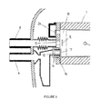
- Figure 3 shows a first embodiment of the remotely actuated suction valve of the sys-tem according to the invention, in the closed state
- Figure 4 shows the same view of figure 3 but with the remotely actuated suction valve in the open state
- Figure 5 shows a second embodiment of the remotely actuated suction valve of the system according to the invention in the open state
- Figure 6 shows the valve of Figure 5 in the closed state
- Figure 7 shows an operating chart of the system in accordance with the present invention, wherein a variable capacity compressor is used
- Figure 8 shows an operating chart of the system in accordance with the invention, wherein a fixed capacity compressor is used
- Figure 9 shows an enlarged detail of a compressor including a suction inlet equalized with the housing compressor (in addition to other hermetic suction inlet);
- Figure 10 also schematically shows an optional embodiment of the suction system for fluid compressors.
- Figure 2 shows the system according to the invention, wherein a compressor 1 is attached to a condenser 3 by a segment of a refrigerant discharge tube 2, said segment leaving from a discharge valve 2a. It can be observed a first refrigerant line 4 having an expansion device 5 and an evaporator 6 arranged in the cooling compartment 7, as well as second refrigerant line 8 having an expansion device 9 and an evaporator 10 arranged in the freezer 11.
- the expansion devices are capillary tubes.
- the compressor 1 has two suction inlets 12 and 13, wherein the first refrigerant line 4 is connected to the first inlet 12 and the second refrigerant line 8 is connected to the second inlet 13. The pressure is greater in the first refrigerant line 4 than in the second line 8.
- a remotely actuated suction valve 14 is arranged in the first suction inlet 12, the remotely actuated suction valve being preferably a solenoid valve.
- the solenoid valve opens and refrigerant of line 4, which is at a higher pressure, occupies the compression chamber and prevents the opening of the another suction valve 15 disposed in the second suction inlet 13.
- the solenoid valve 14 closes and the refrigerant is com-pressed and flows through the discharge tube 2.
- the solenoid valve 14 remains closed and the valve 15 opens, thereby allowing the refrigerant in the second line 8 to be sucked and subsequently compressed and discharged.
- the operation exchange of a suction line to another is preferably done very quick, and thus, the system interprets as if the two lines were operating simultaneously, which allows the operation of the system without the use of temperature ranges, with a nearly constant temperature in the freezer, for example - 18 °C, and a constant temperature within the cooling compartment, for example 5 °C.
- Figure 3 shows a first embodiment of the remotely actuated valve 14, consisting of a solenoid valve disposed on the suction inlet 12.
- This figure shows that the coil 16 of the valve is mounted in the interior of the suction inlet 12 and the counter-seat 17 of the valve is inside the compression chamber 18, in closed condition/state. In this condition, the coil 16 is actuated, thereby preventing the opening of the solenoid valve 14, and, thus, enabling the opening of the valve 15 as shown in this figure.
- Figure 4 shows the same view of Figure 3 , but in this figure the coil 16 is not energized and the solenoid valve 14 is open, thus preventing the opening of the suction valve 15.
- Figure 5 shows a second embodiment of the solenoid valve 14, wherein the coil 16 is mounted on the first refrigerant line 4 and the counter-seat 17 of the valve operates outside the compression chamber 18. This embodiment has the advantage of using a smaller space inside the cylinder, since the electromagnetic circuit is located in the suction line. It can also be observed in the figure that the solenoid valve 14 is in the open condition while the suction valve 15 is closed. While the valve 17 is open, the suction valve 18 can open and close several times.
- Figure 6 shows the valve of Figure 5 in the closed condition, that is, with a counter seat 17 closing the suction inlet 12, while the suction valve 15 is open.
- Figures 7 and 8 show charts of capacity and operating time of compressor used in the system according to the invention, wherein figure 6 shows the operation of a variable capacity compressor and figure 7 shows the operation of a fixed capacity compressor.
- the variable capacity compressor operates continuously, without interruptions, only increasing or decreasing its speed according to the need for operation, while the fixed capacity compressor stops its operation at certain intervals, according to the sections indicated with "off" in Figure 7 .
- the freezer and refrigeration compartment operate with fairly constant temperatures, the stop intervals of the fixed capacity compressor are greatly reduced.
- the same inventive concept can be applied to other alternatives or possibilities of using the invention.
- the system according to the present invention can employ any type of compressor and not only the linear compressor shown in figures.
- the system could have multiple suction inlets of multiple compartments with different operating temperatures.
- Figure 9 shows an enlarged detail of a compressor including a suction inlet equalized with the compressor housing, wherein a compressor 1b is provided with three nozzles: one outlet nozzle provided with a discharge valve 2b for connection of a refrigerant discharge tube (not shown), an inlet nozzle 3b connected to a hole 31b of the compressor housing 1b, and a second inlet nozzle 4b not connected to the compressor housing 1b.
- a suction valve 5b In the inlet nozzle 3b there is a suction valve 5b.
- a solenoid valve 6b In the inlet nozzle 4b there is a solenoid valve 6b internally containing a coil 61b and a counter seat 62b located inside the compression chamber 7b.
- the first refrigerant line 8b hermetically couples to the hole 31b of the housing and to the compressor 1b.
- the second refrigerant inlet 9b couples to the housing without establishing a physical connection with the end 41b of the inlet nozzle 4b. This configuration allows the pressure equalization between the refrigerant inlet 9b and the compressor housing 1b.
- a suction system for fluid compressor having only one suction inlet.
- This suction system allows a compressor having only one suction inlet to operate similarly to the compressor having two suction inlets previously described, and therefore, the suction system for fluid compressor may also be implemented in a cooling system of a refrigerator, particularly of a household refrigerator having a refrigerator compartment and a freezer.
- the suction system for fluid compressor has no limitation of use applications.
- the suction system for fluid compressor is schematically illustrated in Figure 10 .
- the fluid compressor 1c which is preferably of the electrical type, is housed within the crankcase 2c, and has at least one suction inlet 11c and at least one fluid outlet 12C.
- the suction system for fluid compressor itself comprises at least one fluid selection device 3c, which provides at least one fluid outlet channel 31c and at least two fluid inlet channels 32c.
- the fluid output 31c of the fluid selection device 3c is directly connected to one of the at least one suction inlets 11c of the fluid compressor 1c.
- Each one of the fluid inlets 32c receives a single line and/or fluid tube 41c, 42c.
- Each one among the lines and/or fluid tubes 41c, 42c has an own internal pressure and preferably different from the internal pressure of the other lines and/or fluid tubes 41c, 42c. This allows the fluid compressor 1c to work with different supply pressures.
- the fluid selection device 3c comprises a pneumatic directional three-way / two position valve, electrically driven via a solenoid.
- the solenoid is remotely actuated.
- the line and/or tubing 41C (high pressure) is connected to any of the fluid inlet channels 32c, while the line and/or tubing 42c (low pressure) is connected to the other fluid inlet channel 32c.
- the fluid outlet channel 31c of the fluid selection device 3c is directly connected to at least one suction inlet 11c of the fluid compressor 1c.
- one of the lines and/or tubing 41c, 42c is hermetic (with pressurized fluid isolated from the external environment), while the other line and/ or tubing 41c, 42c is equalized with the housing of the fluid compressor 1c.
- the fluid selection device 3c when actuated, selectively directs the pressurized fluid from one of the lines or tubes 41c, 42c into the fluid compressor 1c, wherein the conventional process of compression and exhaustion of the pressurized fluids occurs.
- the direct connection between the fluid outlet 31c of the fluid selection device 3c and a suction inlet 11c of the fluid compressor 1c annuls any possibility of parasite volume at high pressure/low pressure during the alternating cycles of high and low pressure. This allows that the fluid selection device 3c can be repeatedly actuated in a short period of time, driven the switching (in high frequency) of the working pressure, which is selectively obtained through the lines and/or tubes 41c, 42c.
- the fluid selection device 3c can further comprise (instead of pneumatic directional three-way / two positions valve), an interconnection of a simple directional valve (on/off) with a unidirectional valve.
- the simple directional switching valve is accomplished via a solenoid by remote actuation.
Landscapes
- Engineering & Computer Science (AREA)
- Mechanical Engineering (AREA)
- General Engineering & Computer Science (AREA)
- Physics & Mathematics (AREA)
- Thermal Sciences (AREA)
- Chemical & Material Sciences (AREA)
- Combustion & Propulsion (AREA)
- Compressor (AREA)
- Applications Or Details Of Rotary Compressors (AREA)
- Devices That Are Associated With Refrigeration Equipment (AREA)
Abstract
Description
- The present invention relates to a cooling system of a refrigerator, particularly in a domestic refrigerator having a cooling compartment and a freezer, and also to a process to operate the system. The present invention also relates to a suction system of the fluid compressor in the cooling herein disclosed.
- It known that a cooling system basically comprises a compressor, a condenser, an expansion device and an evaporator. The refrigerant (in its gaseous phase) is compressed in the compressor and flows to the condenser, where it is cooled, for example, by the air, and passes to the liquid phase. The refrigerant in high pressure, flows to the expansion device, where its pressure is reduced, and then flows to the evaporator and absorbs heat from the load (for example, food) and passes into the gas phase. Finally, the refrigerant is sucked by the compressor, thus completing the refrigeration cycle.
- It is known various types of refrigeration systems of household refrigerators. The most commonly used cooling systems comprise a compressor and a condenser, from where a refrigerant line leaves to the evaporator of the freezer, and then this line passes through the evaporator of the refrigeration compartment and returns to the compressor.
- Although the system described above has lower costs, it is inefficient since it operates at lower temperatures, i.e. at the temperature of the freezer.
- In other cooling systems of the prior art there are two completely independent systems, one operating in the freezer and the other operating in the refrigeration compartment. This configuration provides a good efficiency, although its cost is very high, since it has two compressors and two capacitors.
- An alternative to these cooling systems is described in document
U.S. 5,531,078 , which discloses a system especially suitable for use in a dual evaporator refrigeration cycle (having at least two independent climate chambers). This system uses only one fluid compressor provided with a single suction inlet and a single pressured outlet. The suction inlet is supplied by a suction system that consists of a single main suction line, which comes from the junction of two intermediate suction lines. The above suction lines are also known as return lines (thus, the suction system described in documentU.S. 5,531,078 provides two intermediate return lines and a return final line). - The cooling system described in document
U.S. 5,531,078 is best illustrated inFigure 1 , wherein it becomes possible to verify that the union of the two intermediate suction lines "LIS1" and "LIS2" occurs with the aid of a one-way valve "VU" resulting in a single main suction line "LPS", which is connected to the suction inlet "ES" of the compressor "C". Also according toFigure 1 , it can be verified that at least one of the two intermediate suction lines "LIS1" or "LIS2" has a check valve (on-off) "VB". - The operation of the suction system of the refrigeration system described in document
U.S. 5,531,078 is simple: the intermediate suction line "LIS1" of higher pressure (which has a check-valve "VB") supplies the main suction line "LPS", which supplies the compressor "C". Currently, the unidirectional valve "VU" prevents the pressure in the intermediate suction line "LIS1" to invade the intermediate suction line "LIS2", which has a lower pressure. There-fore, the compressor C is supplied with "high pressure". When the check-calve "VB" interrupts the pressure of the intermediate suction line "LIS1", the low pressure of the main suction line "LIS2" flows through the unidirectional valve "VU" to the main suction line "LPS", and consequently, to the compressor "C". This type of suction system allows that a single compressor with a single suction inlet to be capable of working with two different pressures. This also allows the compressor "C" to work at high and low pressures in alternating cycles, optimizing its energy ratio (compared to other arrangements existing in the state of the art). - However, the suction system of the refrigeration system described in document
U.S. 5,531,078 has a major drawback: the occurrence of parasite volume of high pressure/low pressure in the beginning of the low pressure/high pressure cycles. This parasite volume occurs mainly by the fact that when the check valve "VB" is actuated (which occurs when it is desired to alternate the cycles of high and low pressure), the intermediate suction line LIS1 or the main suction line "LPS" is pressurized with the pressure opposite to the desired working pressure. That is, upon alternating from high pressure to low pressure, the intermediate suction line "LIS1" remains pressurized, and, therefore, part of the cycle to be supplied at low pressure is still being supplied at high pressure. Moreover, upon alternating from low pressure to high pressure, the main suction line "LPS" remains pressurized at low pressure, and, therefore, part of the cycle to be supplied at high pressure is still being supplied at low pres-sure. This negative feature is inadmissible in application where the cycles alternating rate (high pressure and low pressure) is high and not fixed, since the occurrence of parasite volume at high pressure/low pressure will be constant. - It can also be observed that, more broadly and generally speaking, another draw-back of all systems of the prior art consists in the fact that they always operate within temperature ranges, i.e., when the temperature reaches a preset maximum value, the thermostat sends a signal to stop the compressor operation or reduces its rotation (in the case of variable capacity compressors), and when the temperature reaches the lowest value, the system returns to operating at full capacity. These variations also cause high losses.
- The present invention has the objective to provide a cooling system for household refrigerators having a high efficiency at a low cost.
- Another objective of the present invention is to provide a suction system for fluid compressors into which there is no occurrence of parasite volume of high pressure/low pres-sure during cycles of alternation between high and low pressure. In this context, it is also an objective of the present invention to provide a suction system for fluid compressor capable of operating at a high frequency of alternating cycles of high and low pressure.
- The cooling system described herein comprises a compressor associated to at least a condenser of a refrigeration system by a segment of a refrigerant discharge tube, wherein a first refrigerant line leaves from the condenser and returns to the compressor and a second refrigerant line leaves from the condenser and returns to the compressor.
- Thus, the system according to the present invention can operate in a traditional manner, wherein each suction line operates sequentially at a low speed or, preferably, in a very fast rate in which the exchange operation of a suction line to another suction line is processed in a very fast manner, so that the system interprets as if the two lines were operating simultaneously.
- This feature of rapidly exchanging the lines provides high efficiency to the system, causing the refrigerator compartment and freezer operate simultaneously in nearly constant temperatures. Thus, the known losses of the prior art systems, which operate based on temperature ranges, as previously described, can be avoided.
- Another advantage of the system according to the present invention is the fact that you can control the time into which each line is activated, which enables control of the capacity required for each of them. This valve opening time control can be associated with a variable capacity compressor. This combination allows to cover a wide range of capabilities for each suction line, with full control of the capacity of each suction line, in an independent and concurrent manner.
- Another advantage of the system according to the invention is the fact that there is no segment of the suction lines subject to two operating pressures, as occurs in the prior art system shown in
Figure 1 . In view of this, the losses described above can be eliminated. - In reciprocating or linear hermetic compressors applied to household refrigeration systems, the compressor suction is usually equalized with the compressor housing. Thus the housing has the same suction pressure and in cases wherein compressors use oil for lubricating its bearings, it can easily return to the crankcase. Thus, another advantage of the sys-tem according to the invention is the fact that you can choose from one of the suction lines to be equalized with the interior of the housing and also allow oil coming in this line to return to the crankcase. The oil returning by the non-equalized line will be pumped back into the discharge line, where it will mix with the gas coming from the other suction line and part will be moved to the crankcase when returning to the compressor through the equalized suction line. Thus, there will always be a way for the oil to return to the compressor. In compressors where lubricating oil is not used, the two lines could be hermetic if so desired.
- The present invention discloses, according to its preferred embodiment, a cooling system of a refrigerator, particularly of a refrigerator including a refrigeration compartment and a freezer, said system comprising a compressor attached to at least one condenser by a segment of a refrigerant discharge tube, a first refrigerant line leaving from the condenser and returning to the compressor (said first line sequentially carrying an expansion device and an evaporator arranged in the refrigeration compartment), and a second refrigerant line leaving from the condenser and returning to the compressor (said second line sequentially carrying an expansion device and an evaporator arranged in the freezer). The compressor has at least two suction inlets, wherein the first refrigerant line is connected to the first inlet and the second refrigerant line is connected to the second inlet, and both inlets have each a suction valve.
- The suction valve of the first suction inlet is a remotely actuated valve, and preferably, a solenoid valve or a pneumatic valve or a hydraulic valve. The suction valve of the second suction inlet is a mechanically operable valve. The first and second suction valves operate alternately, wherein the alternation operation of the valves occurs preferably quickly.
- The respective expansion devices of the first and second refrigerant lines are preferably capillary tubes.
- At least one inlet line is hermetically coupled to the compression chamber of the compressor. At least one inlet line is equalized to the volume of the compressor housing. At least one inlet nozzle is spaced from the compressor housing and has at least one end remote from its respective inlet line.
- The present invention also shows, according to its optional embodiment, a suction system for fluid compressor capable of association with a fluid compressor and comprising at least one fluid selection device directly connected to at least one suction inlet of the fluid compressor. The said fluid selection device receives at least two supply lines and is capable to selectively switch the pressurized fluid from one of the at least two supply lines to the suction inlet of the fluid compressor. The fluid selection device comprises at least one fluid outlet channel and at least two fluid inlet channels. The fluid selection device comprises a pneumatic directional three-way / two positions valve. More preferably, the actuation of the fluid selection device is electric, via a solenoid. Optionally, the fluid selection device comprises an inter-connection of a simple directional valve - on / off - with a one-way valve.
- Each one of the fluid inlets of the fluid selection device receives a single supply line, and each supply line has its own internal pressure that is different from the internal pressure of the other supply lines. Preferably, at least one of the supply lines is hermetic. Also preferably, at least one of the supply lines is equalized with the pressure of the fluid compressor housing.
-
Figure 1 - schematically and briefly illustrates the suction system of the cooling refrigeration system described in documentU.S. 5,531,078 (with the indicative references previously mentioned); -
Figure 2 shows a preferred embodiment of the refrigeration system in accordance with the invention; -
Figure 3 shows a first embodiment of the remotely actuated suction valve of the sys-tem according to the invention, in the closed state; -
Figure 4 shows the same view offigure 3 but with the remotely actuated suction valve in the open state; -
Figure 5 shows a second embodiment of the remotely actuated suction valve of the system according to the invention in the open state; -
Figure 6 shows the valve ofFigure 5 in the closed state; -
Figure 7 shows an operating chart of the system in accordance with the present invention, wherein a variable capacity compressor is used; -
Figure 8 shows an operating chart of the system in accordance with the invention, wherein a fixed capacity compressor is used; -
Figure 9 shows an enlarged detail of a compressor including a suction inlet equalized with the housing compressor (in addition to other hermetic suction inlet); and -
Figure 10 also schematically shows an optional embodiment of the suction system for fluid compressors. -
Figure 2 shows the system according to the invention, wherein acompressor 1 is attached to acondenser 3 by a segment of arefrigerant discharge tube 2, said segment leaving from a discharge valve 2a. It can be observed a firstrefrigerant line 4 having an expansion device 5 and an evaporator 6 arranged in thecooling compartment 7, as well as secondrefrigerant line 8 having an expansion device 9 and anevaporator 10 arranged in thefreezer 11. Preferably, the expansion devices are capillary tubes. Thecompressor 1 has twosuction inlets refrigerant line 4 is connected to thefirst inlet 12 and the secondrefrigerant line 8 is connected to thesecond inlet 13. The pressure is greater in the firstrefrigerant line 4 than in thesecond line 8. - A remotely actuated
suction valve 14 is arranged in thefirst suction inlet 12, the remotely actuated suction valve being preferably a solenoid valve. Thus, during operation, the solenoid valve opens and refrigerant ofline 4, which is at a higher pressure, occupies the compression chamber and prevents the opening of the anothersuction valve 15 disposed in thesecond suction inlet 13. Then thesolenoid valve 14 closes and the refrigerant is com-pressed and flows through thedischarge tube 2. After this step, thesolenoid valve 14 remains closed and thevalve 15 opens, thereby allowing the refrigerant in thesecond line 8 to be sucked and subsequently compressed and discharged. - As previously mentioned, the operation exchange of a suction line to another is preferably done very quick, and thus, the system interprets as if the two lines were operating simultaneously, which allows the operation of the system without the use of temperature ranges, with a nearly constant temperature in the freezer, for example - 18 °C, and a constant temperature within the cooling compartment, for example 5 °C.
-
Figure 3 shows a first embodiment of the remotely actuatedvalve 14, consisting of a solenoid valve disposed on thesuction inlet 12. This figure shows that thecoil 16 of the valve is mounted in the interior of thesuction inlet 12 and the counter-seat 17 of the valve is inside thecompression chamber 18, in closed condition/state. In this condition, thecoil 16 is actuated, thereby preventing the opening of thesolenoid valve 14, and, thus, enabling the opening of thevalve 15 as shown in this figure. -
Figure 4 shows the same view ofFigure 3 , but in this figure thecoil 16 is not energized and thesolenoid valve 14 is open, thus preventing the opening of thesuction valve 15.Figure 5 shows a second embodiment of thesolenoid valve 14, wherein thecoil 16 is mounted on the firstrefrigerant line 4 and the counter-seat 17 of the valve operates outside thecompression chamber 18. This embodiment has the advantage of using a smaller space inside the cylinder, since the electromagnetic circuit is located in the suction line. It can also be observed in the figure that thesolenoid valve 14 is in the open condition while thesuction valve 15 is closed. While thevalve 17 is open, thesuction valve 18 can open and close several times. -
Figure 6 shows the valve ofFigure 5 in the closed condition, that is, with acounter seat 17 closing thesuction inlet 12, while thesuction valve 15 is open. -
Figures 7 and 8 show charts of capacity and operating time of compressor used in the system according to the invention, whereinfigure 6 shows the operation of a variable capacity compressor andfigure 7 shows the operation of a fixed capacity compressor. As is already known, the variable capacity compressor operates continuously, without interruptions, only increasing or decreasing its speed according to the need for operation, while the fixed capacity compressor stops its operation at certain intervals, according to the sections indicated with "off" inFigure 7 . Considering that in the present invention the freezer and refrigeration compartment operate with fairly constant temperatures, the stop intervals of the fixed capacity compressor are greatly reduced. - In addition to previously described embodiment, the same inventive concept can be applied to other alternatives or possibilities of using the invention. For example, the system according to the present invention can employ any type of compressor and not only the linear compressor shown in figures. In another example, the system could have multiple suction inlets of multiple compartments with different operating temperatures.
-
Figure 9 shows an enlarged detail of a compressor including a suction inlet equalized with the compressor housing, wherein a compressor 1b is provided with three nozzles: one outlet nozzle provided with a discharge valve 2b for connection of a refrigerant discharge tube (not shown), an inlet nozzle 3b connected to a hole 31b of the compressor housing 1b, and a second inlet nozzle 4b not connected to the compressor housing 1b. In the inlet nozzle 3b there is a suction valve 5b. In the inlet nozzle 4b there is a solenoid valve 6b internally containing acoil 61b and a counter seat 62b located inside thecompression chamber 7b. - The first refrigerant line 8b hermetically couples to the hole 31b of the housing and to the compressor 1b.
- The second refrigerant inlet 9b couples to the housing without establishing a physical connection with the end 41b of the inlet nozzle 4b. This configuration allows the pressure equalization between the refrigerant inlet 9b and the compressor housing 1b.
- It should be emphasized that regardless of the amount of inlet lines that may exist in the system, according to the development herein contemplated, at least one of the inlets of at least one of these lines will have a similar configuration to the configuration of the second refrigerant inlet 9b (to allow the pressure equalization and the eventual return of the lubricating oil existing in the inlet line into the interior the housing).
- In accordance with the objectives of the present invention, it is also presented an optional version of the embodiment previously described.
- According to this optional embodiment, and as illustrated in
Figure 10 , it is shown a suction system for fluid compressor having only one suction inlet. This suction system allows a compressor having only one suction inlet to operate similarly to the compressor having two suction inlets previously described, and therefore, the suction system for fluid compressor may also be implemented in a cooling system of a refrigerator, particularly of a household refrigerator having a refrigerator compartment and a freezer. However, the suction system for fluid compressor has no limitation of use applications. - The suction system for fluid compressor is schematically illustrated in
Figure 10 . In this figure it can be seen that thefluid compressor 1c, which is preferably of the electrical type, is housed within thecrankcase 2c, and has at least onesuction inlet 11c and at least one fluid outlet 12C. - Also according to
Figure 10 , it should be noticed that the suction system for fluid compressor itself comprises at least onefluid selection device 3c, which provides at least onefluid outlet channel 31c and at least twofluid inlet channels 32c. - The
fluid output 31c of thefluid selection device 3c is directly connected to one of the at least onesuction inlets 11c of thefluid compressor 1c. - Each one of the
fluid inlets 32c receives a single line and/orfluid tube fluid tubes fluid tubes fluid compressor 1c to work with different supply pressures. - The
fluid selection device 3c comprises a pneumatic directional three-way / two position valve, electrically driven via a solenoid. Preferably, the solenoid is remotely actuated. - The line and/or tubing 41C (high pressure) is connected to any of the
fluid inlet channels 32c, while the line and/ortubing 42c (low pressure) is connected to the otherfluid inlet channel 32c. It should again be noted that thefluid outlet channel 31c of thefluid selection device 3c is directly connected to at least onesuction inlet 11c of thefluid compressor 1c. - Preferably, one of the lines and/or
tubing tubing fluid compressor 1c. - The operation of the suction system for fluid compressor herein proposed is as follows: the
fluid selection device 3c, when actuated, selectively directs the pressurized fluid from one of the lines ortubes fluid compressor 1c, wherein the conventional process of compression and exhaustion of the pressurized fluids occurs. - The direct connection between the
fluid outlet 31c of thefluid selection device 3c and asuction inlet 11c of thefluid compressor 1c annuls any possibility of parasite volume at high pressure/low pressure during the alternating cycles of high and low pressure. This allows that thefluid selection device 3c can be repeatedly actuated in a short period of time, driven the switching (in high frequency) of the working pressure, which is selectively obtained through the lines and/ortubes - Optionally, the
fluid selection device 3c can further comprise (instead of pneumatic directional three-way / two positions valve), an interconnection of a simple directional valve (on/off) with a unidirectional valve. Preferably, the simple directional switching valve is accomplished via a solenoid by remote actuation. - Again, it is important to emphasize that the interconnection of a simple directional valve (on / off) with a unidirectional valve (having at least two inlet channels and one outlet channel) is directly connected to at least one
suction inlet 11c offluid compressor 1c. - Having described specific examples of the present invention, it should be understood that the scope it covers other possible variations, being limited solely by the wording of claims, including the possible equivalents therein.
Claims (18)
- A cooling system of a refrigerator, particularly of a refrigerator including a refrigeration compartment (7) and a freezer (11), said system comprising a compressor (1) attached to at least one condenser (3) by a segment of a refrigerant discharge tube (2), a first refrigerant line (4) leaving from the condenser (3) and returning to the compressor (1), said first line (4) sequentially carrying an expansion device (5) and an evaporator (6) arranged in the refrigeration compartment (7), and a second refrigerant line (8) leaving from the condenser (3) and returning to the compressor (1), said second line (8) sequentially carrying an expansion device (9) and an evaporator (10) arranged in the freezer (11), characterized by the fact that the compressor (1) has at least two suction inlets (12, 13), wherein the first refrigerant line (4) is connected to the first inlet (12) and the second refrigerant line (8) is connected to the second inlet (13), and both inlets have each a suction valve (14, 15).
- A cooling system according to claim 1, characterized by the fact that the suction valve (14) of the first suction inlet (12) is a remotely actuated valve.
- A cooling system according to claim 2, characterized by the fact that the remotely actuated valve is a solenoid valve.
- A cooling system according to claim 2, characterized by the fact that the remotely actuated valve is a pneumatic valve.
- A cooling system according to claim 2, characterized by the fact that the remotely actuated valve is a hydraulic valve.
- A cooling system according to claim 1, characterized by the fact that the suction valve (15) of the second suction inlet (13) is a mechanically operable valve.
- A cooling system according to claim 1, characterized by the fact that the respective expansion devices (5, 9) of the first and second refrigerant lines (4, 8) are preferably capillary tubes.
- A cooling system according to claim 1, characterized by the fact that the first and second suction valves (14, 15) operate in an alternate manner, wherein the alternation operation of the valves occurs preferably quickly.
- A cooling system according to any one of claims 1 to 8, characterized by the fact that it further includes: at least one inlet line (8c) hermetically coupled to the compression chamber (7c) of the compressor (1c); at least one inlet line (9c) equalized to the volume of the compressor housing (1c); and at least one inlet nozzle (4c) being spaced from the compressor housing (1c) and having at least one end (41c) remote from their respective inlet line.
- A suction system for fluid compressor comprising a system capable of association with a fluid compressor (1c), characterized by comprising:at least one fluid selection device (3c) directly connected to at least one suction inlet (11c) of the fluid compressor (1c);the fluid selection device (3c) receiving at least two supply lines (41c, 42c);the fluid selection device (3c) being able to selectively switch the pressurized fluid from one of the at least two supply lines (41c, 42c) to the suction inlet (11c) of the fluid compressor (1c).
- A system according to claim 10, characterized by the fact that the fluid selection device (3c) comprises at least one fluid outlet channel (31c) and at least two fluid inlet channels (32c).
- A system according to claim 11, characterized by the fact that the fluid selection device (3c) comprises a pneumatic directional three-way / two positions valve.
- A system according to claim 11, characterized by the fact that the actuation of the fluid selection device (3c) is electric, via a solenoid.
- A system according to claim 10 or 11, characterized by the fact that each one of the fluid inlets (32c) of the fluid selection device (3c) receives a single supply line (41c, 42c).
- A system according to claim 11, characterized by the fact that each supply line (41c, 42c) has its own internal pressure that is different from the internal pressure of the other supply lines (41c, 42c).
- A system according to claim 15, characterized by the fact that at least one of the supply lines (41c, 42c) is hermetic.
- A system according to claim 15, characterized by the fact that at least one of the supply lines (41c, 42c) is equalized with the pressure of the fluid compressor housing (1c).
- A system according to claim 10, characterized by the fact that the fluid selection device (3c) comprises an interconnection of a simple directional valve - on / off - with a one-way valve.
Applications Claiming Priority (3)
| Application Number | Priority Date | Filing Date | Title |
|---|---|---|---|
| BRC11001359-8A BRPI1001359C1 (en) | 2010-04-26 | 2010-04-26 | cooling system of a refrigerator |
| BRPI1101972-7A BRPI1101972B1 (en) | 2011-04-25 | 2011-04-25 | SUCTION SYSTEM FOR FLUID COMPRESSOR |
| PCT/BR2011/000120 WO2011134030A2 (en) | 2010-04-26 | 2011-04-26 | Cooling system of a refrigerator and suction system for a compressor fluid |
Publications (1)
| Publication Number | Publication Date |
|---|---|
| EP2581690A2 true EP2581690A2 (en) | 2013-04-17 |
Family
ID=47846230
Family Applications (1)
| Application Number | Title | Priority Date | Filing Date |
|---|---|---|---|
| EP11730872.6A Withdrawn EP2581690A2 (en) | 2010-04-26 | 2011-04-26 | Cooling system of a refrigerator and suction system for a compressor fluid |
Country Status (6)
| Country | Link |
|---|---|
| US (2) | US9335084B2 (en) |
| EP (1) | EP2581690A2 (en) |
| JP (1) | JP6023043B2 (en) |
| KR (1) | KR20130058683A (en) |
| CN (1) | CN102947652B (en) |
| WO (1) | WO2011134030A2 (en) |
Cited By (4)
| Publication number | Priority date | Publication date | Assignee | Title |
|---|---|---|---|---|
| EP2772702A1 (en) * | 2013-02-28 | 2014-09-03 | Whirlpool Corporation | Dual suction compressor with rapid suction port switching mechanism for matching appliance compartment thermal loads with cooling capacity |
| DE102013011050A1 (en) * | 2013-04-22 | 2014-10-23 | Liebherr-Hausgeräte Ochsenhausen GmbH | Cooling and / or Gerfriergerät |
| EP3144605A1 (en) * | 2015-09-15 | 2017-03-22 | Whirlpool S.A. | Multi-evaporation cooling system |
| US20180274530A1 (en) * | 2013-02-15 | 2018-09-27 | Whirlpool S.A. | Method for Actuating Semi-Commanded Valve and System for Actuating Semi-Commanded Valve for Multi-Suction Alternative Compressor |
Families Citing this family (16)
| Publication number | Priority date | Publication date | Assignee | Title |
|---|---|---|---|---|
| CN102947652B (en) * | 2010-04-26 | 2015-04-08 | 惠而浦股份有限公司 | Refrigerator cooling system and suction system for compressor fluid |
| US20130255290A1 (en) * | 2012-04-02 | 2013-10-03 | Whirlpool Corporation | Energy efficiency of air conditioning system by using dual suction compressor |
| US20130255309A1 (en) * | 2012-04-02 | 2013-10-03 | Whirlpool Corporation | Energy efficiency of room air conditioner or unitary air conditioning system by using dual suction compressor |
| US9599353B2 (en) * | 2013-07-26 | 2017-03-21 | Whirlpool Corporation | Split air conditioning system with a single outdoor unit |
| BR102013024565A2 (en) * | 2013-09-25 | 2015-09-15 | Whirlpool Sa | compressor electric motor operation control system and compressor electric motor operation control method |
| BR102014007259A2 (en) * | 2014-03-26 | 2015-12-08 | Whirlpool Sa | reciprocating compressor fitted with suction valve arrangement |
| BR102014007254A2 (en) * | 2014-03-26 | 2015-12-08 | Whirlpool Sa | fluid selector device for reciprocating compressor and acoustic filter provided with fluid selector device |
| BR102014007252A2 (en) * | 2014-03-26 | 2015-12-08 | Whirlpool Sa | reciprocating compressor fitted with suction valve arrangement |
| BR102014029659B1 (en) * | 2014-11-27 | 2022-01-11 | Embraco Indústria De Compressores E Soluções Em Refrigeração Ltda | ACOUSTIC SUCTION FILTER AND SUCTION LINE INCLUDING ACOUSTIC SUCTION FILTER |
| BR102015006163A2 (en) * | 2015-03-19 | 2016-10-18 | Whirlpool Sa | reciprocating compressor including acoustic suction filter |
| JP6754370B2 (en) | 2015-03-19 | 2020-09-09 | エンブラコ インドゥストリア デ コンプレッソレス エー ソリューションズ エン レフリジラサン リミターダ | Suction acoustic filter for compressor |
| BR102015021009B1 (en) * | 2015-08-31 | 2022-05-03 | Embraco Indústria De Compressores E Soluções Em Refrigeração Ltda | Method and system of protection and diagnosis of a linear compressor and linear compressor |
| BR202017006118Y1 (en) | 2017-03-24 | 2022-12-20 | Whirlpool S.A. | EVAPORATOR FOR REFRIGERATION SYSTEM |
| CN109883104A (en) * | 2018-12-27 | 2019-06-14 | 青岛海尔特种制冷电器有限公司 | Refrigerator and its control method |
| CN116163927B (en) * | 2022-02-18 | 2026-03-03 | 安徽美芝制冷设备有限公司 | Compressor and refrigeration equipment |
| US12584468B2 (en) * | 2023-02-28 | 2026-03-24 | Spm Oil & Gas Inc. | Fluid system with a proppant mixing pump |
Family Cites Families (26)
| Publication number | Priority date | Publication date | Assignee | Title |
|---|---|---|---|---|
| US2333899A (en) * | 1934-05-25 | 1943-11-09 | Gen Motors Corp | Refrigerating apparatus |
| US2123497A (en) * | 1936-11-11 | 1938-07-12 | Westinghouse Electric & Mfg Co | Two-temperature refrigerating apparatus |
| US2481605A (en) | 1944-07-10 | 1949-09-13 | Seeger Refrigerator Co | Refrigerator system |
| CH271484A (en) * | 1948-12-23 | 1950-10-31 | Sulzer Ag | Operating procedures for refrigeration systems and heat pumps. |
| US2976698A (en) | 1951-09-19 | 1961-03-28 | Muffly Glenn | Reversible refrigerating systems |
| US3108453A (en) * | 1959-08-05 | 1963-10-29 | Mrs Bonita E Runde | Refrigerating apparatus including heat exchange stabilizer means |
| US3759057A (en) * | 1972-01-10 | 1973-09-18 | Westinghouse Electric Corp | Room air conditioner having compressor with variable capacity and control therefor |
| US4184341A (en) | 1978-04-03 | 1980-01-22 | Pet Incorporated | Suction pressure control system |
| US4373870A (en) * | 1980-07-17 | 1983-02-15 | General Motors Corporation | Variable capacity positive displacement type compressor |
| JPS6048463A (en) * | 1983-08-25 | 1985-03-16 | 株式会社デンソー | Air-cooling refrigerator |
| JPS6172966A (en) * | 1984-09-17 | 1986-04-15 | 株式会社デンソー | Refrigerant compressor |
| JPS61105059A (en) * | 1984-10-25 | 1986-05-23 | 株式会社東芝 | Compressor |
| JPS61184364A (en) * | 1985-02-13 | 1986-08-18 | 株式会社デンソー | Rotary vane type compressor |
| US5228308A (en) * | 1990-11-09 | 1993-07-20 | General Electric Company | Refrigeration system and refrigerant flow control apparatus therefor |
| TW222342B (en) | 1992-03-31 | 1994-04-11 | Motorola Lac | |
| JP3413857B2 (en) | 1992-12-09 | 2003-06-09 | 凸版印刷株式会社 | Method for producing metal oxide deposited film |
| JP3435189B2 (en) * | 1993-07-09 | 2003-08-11 | 株式会社東芝 | Refrigeration equipment for refrigerators |
| US5531078A (en) * | 1994-12-27 | 1996-07-02 | General Electric Company | Low volume inlet reciprocating compressor for dual evaporator refrigeration system |
| US6213731B1 (en) | 1999-09-21 | 2001-04-10 | Copeland Corporation | Compressor pulse width modulation |
| JP2005134080A (en) * | 2003-10-31 | 2005-05-26 | Toshiba Corp | Refrigerator |
| EP1783443A4 (en) * | 2004-08-06 | 2012-12-05 | Daikin Ind Ltd | FREEZING DEVICE |
| US7353660B2 (en) * | 2004-09-13 | 2008-04-08 | Carrier Corporation | Multi-temperature cooling system with unloading |
| US7114349B2 (en) * | 2004-12-10 | 2006-10-03 | Carrier Corporation | Refrigerant system with common economizer and liquid-suction heat exchanger |
| KR100747496B1 (en) * | 2006-11-27 | 2007-08-08 | 삼성전자주식회사 | Rotary compressor and its control method and air conditioner using the same |
| CN102947652B (en) * | 2010-04-26 | 2015-04-08 | 惠而浦股份有限公司 | Refrigerator cooling system and suction system for compressor fluid |
| BRPI1005090A2 (en) * | 2010-12-10 | 2013-04-02 | Whirlpool Sa | Double suction compressor control methods for refrigeration systems |
-
2011
- 2011-04-26 CN CN201180028408.4A patent/CN102947652B/en not_active Expired - Fee Related
- 2011-04-26 EP EP11730872.6A patent/EP2581690A2/en not_active Withdrawn
- 2011-04-26 WO PCT/BR2011/000120 patent/WO2011134030A2/en not_active Ceased
- 2011-04-26 JP JP2013506415A patent/JP6023043B2/en not_active Expired - Fee Related
- 2011-04-26 US US13/643,862 patent/US9335084B2/en not_active Expired - Fee Related
- 2011-04-26 KR KR1020127028991A patent/KR20130058683A/en not_active Ceased
-
2014
- 2014-10-10 US US14/511,455 patent/US20150020538A1/en not_active Abandoned
Non-Patent Citations (2)
| Title |
|---|
| None * |
| See also references of WO2011134030A2 * |
Cited By (7)
| Publication number | Priority date | Publication date | Assignee | Title |
|---|---|---|---|---|
| US20180274530A1 (en) * | 2013-02-15 | 2018-09-27 | Whirlpool S.A. | Method for Actuating Semi-Commanded Valve and System for Actuating Semi-Commanded Valve for Multi-Suction Alternative Compressor |
| US10731642B2 (en) * | 2013-02-15 | 2020-08-04 | Embraco—Industria De Compressores E Solucoes Em Refrigeracao Ltda. | Method for actuating semi-commanded valve and system for actuating semi-commanded valve for multi-suction alternative compressor |
| US10774827B2 (en) | 2013-02-15 | 2020-09-15 | Embraco Industria de Compressores e Solucoes em Refrigeracao Ltda. | Method for actuating semi-commanded valve and system for actuating semi-commanded valve for multi-suction alternative compressor |
| EP2772702A1 (en) * | 2013-02-28 | 2014-09-03 | Whirlpool Corporation | Dual suction compressor with rapid suction port switching mechanism for matching appliance compartment thermal loads with cooling capacity |
| DE102013011050A1 (en) * | 2013-04-22 | 2014-10-23 | Liebherr-Hausgeräte Ochsenhausen GmbH | Cooling and / or Gerfriergerät |
| EP2796812A1 (en) * | 2013-04-22 | 2014-10-29 | Liebherr-Hausgeräte Ochsenhausen GmbH | Refrigeration and/or freezer device |
| EP3144605A1 (en) * | 2015-09-15 | 2017-03-22 | Whirlpool S.A. | Multi-evaporation cooling system |
Also Published As
| Publication number | Publication date |
|---|---|
| WO2011134030A2 (en) | 2011-11-03 |
| US20150020538A1 (en) | 2015-01-22 |
| CN102947652B (en) | 2015-04-08 |
| WO2011134030A3 (en) | 2012-07-19 |
| KR20130058683A (en) | 2013-06-04 |
| JP2013528769A (en) | 2013-07-11 |
| US20130160482A1 (en) | 2013-06-27 |
| JP6023043B2 (en) | 2016-11-09 |
| US9335084B2 (en) | 2016-05-10 |
| CN102947652A (en) | 2013-02-27 |
Similar Documents
| Publication | Publication Date | Title |
|---|---|---|
| US9335084B2 (en) | Cooling system of a refrigerator and suction system for a compressor fluid | |
| US5600961A (en) | Refrigeration system with dual cylinder compressor | |
| KR101280155B1 (en) | Heat pump device, two-stage compressor, and method of operating heat pump device | |
| US8671704B2 (en) | Refrigeration system with intermediate pressure vapor supply valve | |
| US7478539B2 (en) | Two-stage linear compressor | |
| CN112360716B (en) | Double-cylinder two-stage compressor, refrigerating system control method and refrigerator | |
| US20120192583A1 (en) | Suction Cutoff Unloader Valve For Compressor Capacity Control | |
| US20170254572A1 (en) | Air conditioning system and method for controlling same | |
| US7213405B2 (en) | Two-stage linear compressor | |
| US6584791B2 (en) | Pressure equalization system and method | |
| CN112049769B (en) | Piston compressor and refrigeration equipment | |
| WO2006098808A2 (en) | Dual mode compressor with automatic compression ratio adjustment for adapting to multiple operating conditions | |
| CN112855491B (en) | A compressor, refrigerator and control method | |
| CN111928509B (en) | Refrigerator refrigerating system, control method thereof and refrigerator | |
| CN107989768B (en) | Compressors and refrigeration equipment | |
| CN217976514U (en) | Reciprocating type refrigeration compressor | |
| CN107816816B (en) | Refrigerating device | |
| JPH11304271A (en) | Cool storage refrigerator and superconducting magnet system using the same | |
| BRPI1001359A2 (en) | one-refrigerator cooling system and system operation process | |
| CN105814375B (en) | Cold Heads for Refrigerators | |
| US2492610A (en) | Refrigeration | |
| KR100202595B1 (en) | Refrigeration control device of refrigeration cycle | |
| EP1913312A1 (en) | Refrigeration system comprising multiple refrigeration consumer devices |
Legal Events
| Date | Code | Title | Description |
|---|---|---|---|
| PUAI | Public reference made under article 153(3) epc to a published international application that has entered the european phase |
Free format text: ORIGINAL CODE: 0009012 |
|
| PUAB | Information related to the publication of an a document modified or deleted |
Free format text: ORIGINAL CODE: 0009199EPPU |
|
| PUAI | Public reference made under article 153(3) epc to a published international application that has entered the european phase |
Free format text: ORIGINAL CODE: 0009012 |
|
| 17P | Request for examination filed |
Effective date: 20121026 |
|
| AK | Designated contracting states |
Kind code of ref document: A2 Designated state(s): AL AT BE BG CH CY CZ DE DK EE ES FI FR GB GR HR HU IE IS IT LI LT LU LV MC MK MT NL NO PL PT RO RS SE SI SK SM TR |
|
| DAX | Request for extension of the european patent (deleted) | ||
| STAA | Information on the status of an ep patent application or granted ep patent |
Free format text: STATUS: EXAMINATION IS IN PROGRESS |
|
| 17Q | First examination report despatched |
Effective date: 20171020 |
|
| GRAP | Despatch of communication of intention to grant a patent |
Free format text: ORIGINAL CODE: EPIDOSNIGR1 |
|
| STAA | Information on the status of an ep patent application or granted ep patent |
Free format text: STATUS: GRANT OF PATENT IS INTENDED |
|
| RIC1 | Information provided on ipc code assigned before grant |
Ipc: F25D 11/02 20060101ALI20201221BHEP Ipc: F04B 39/06 20060101AFI20201221BHEP Ipc: F25B 5/02 20060101ALI20201221BHEP Ipc: F25B 41/04 20060101ALI20201221BHEP Ipc: F25B 1/02 20060101ALI20201221BHEP |
|
| INTG | Intention to grant announced |
Effective date: 20210126 |
|
| RIC1 | Information provided on ipc code assigned before grant |
Ipc: F25B 5/02 20060101ALI20210119BHEP Ipc: F25B 1/02 20060101ALI20210119BHEP Ipc: F25D 11/02 20060101ALI20210119BHEP Ipc: F25B 41/22 20210101ALI20210119BHEP Ipc: F04B 39/06 20060101AFI20210119BHEP |
|
| STAA | Information on the status of an ep patent application or granted ep patent |
Free format text: STATUS: THE APPLICATION IS DEEMED TO BE WITHDRAWN |
|
| 18D | Application deemed to be withdrawn |
Effective date: 20210608 |