EP2581477A1 - Information display apparatus for loom - Google Patents
Information display apparatus for loom Download PDFInfo
- Publication number
- EP2581477A1 EP2581477A1 EP12005930.8A EP12005930A EP2581477A1 EP 2581477 A1 EP2581477 A1 EP 2581477A1 EP 12005930 A EP12005930 A EP 12005930A EP 2581477 A1 EP2581477 A1 EP 2581477A1
- Authority
- EP
- European Patent Office
- Prior art keywords
- warp
- fell
- cloth
- healds
- shed
- Prior art date
- Legal status (The legal status is an assumption and is not a legal conclusion. Google has not performed a legal analysis and makes no representation as to the accuracy of the status listed.)
- Granted
Links
- 238000010586 diagram Methods 0.000 claims abstract description 19
- 239000004744 fabric Substances 0.000 claims description 66
- 239000006185 dispersion Substances 0.000 claims description 24
- 238000009941 weaving Methods 0.000 description 31
- 238000012360 testing method Methods 0.000 description 11
- 238000004364 calculation method Methods 0.000 description 10
- 230000000007 visual effect Effects 0.000 description 10
- 238000001514 detection method Methods 0.000 description 8
- 238000006073 displacement reaction Methods 0.000 description 8
- 230000006870 function Effects 0.000 description 3
- 238000012937 correction Methods 0.000 description 2
- 238000012986 modification Methods 0.000 description 2
- 230000004048 modification Effects 0.000 description 2
- 235000014676 Phragmites communis Nutrition 0.000 description 1
- 230000000694 effects Effects 0.000 description 1
- 238000005516 engineering process Methods 0.000 description 1
- 238000011156 evaluation Methods 0.000 description 1
- 239000004973 liquid crystal related substance Substances 0.000 description 1
- 230000007935 neutral effect Effects 0.000 description 1
Images




Classifications
-
- D—TEXTILES; PAPER
- D03—WEAVING
- D03J—AUXILIARY WEAVING APPARATUS; WEAVERS' TOOLS; SHUTTLES
- D03J1/00—Auxiliary apparatus combined with or associated with looms
- D03J1/005—Displays or displaying data
Definitions
- the present invention relates to an information display apparatus for a loom.
- the invention relates to an information display apparatus for a loom that at least includes, as a plurality of members that influence a warp path, a warp guide roller and healds attached to each of a plurality of heald frames, and in which warp yarns that are let off from a warp beam are redirected toward a cloth fell by the warp guide roller, passed through the healds of corresponding ones of the heald frames, and guided to the cloth fell.
- warp yarns 101 are let off from a warp beam 102 around which the warp yarns 101 are wound, fed over a plurality of guide rollers 103 for guiding the warp yarns 101 (including a tension roller 105 that detects the warp tension with a tension sensor 104, the same applying hereinafter), and redirected toward a cloth fell 106.
- the warp yarns 101 are guided through a dropper device 107, which is a warp yarn breakage detection device for detecting warp yarn breakage, are passed through healds 109 of a plurality of heald frames 108 that are arranged, and reach the cloth fell 106.
- a shed is formed by the warp yarns 101.
- a weft yarn 110 is inserted into the shed and beaten up toward the cloth fell 106 by a reed 111 so as to be weaved into the warp yarns 101, and thereby a fabric 112 is formed.
- the fabric 112, which has been woven in this way, passes over a surface roller 113 and the like and is taken up by a take-up roller 114.
- the path of the warp yarns 101 (hereinafter simply referred to as the "warp path” in the present application) from one of the guide rollers 103 that is located nearest to the healds 109 (hereinafter referred to as a "warp guide roller", which corresponds to the tension roller 105 in the example illustrated in Fig. 1 ) to the cloth fell 106 is adjusted in a pre-weaving operation that is performed before weaving is started in accordance with weaving conditions (such as the types of the warp yarns 101 and the weft yarn 110, and set tension and the like of the warp yarns 101). Since the warp path changes due to shedding motion of the warp yarns 101, one or both of the warp path that exists when the shed is closed and the warp path that exists when the shed is open is/are adjusted.
- the warp path is determined in accordance with the positional relationship between the cloth fell 106 and a plurality of members that exist on the warp path and that influence the warp path, such as the tension roller 105, the dropper device 107, the healds 109 of the heald frames 108, and the like. Therefore, the aforementioned adjustment is performed by adjusting the position of at least one of the plurality of members that influence the warp path. To be specific, the adjustment is performed by changing the position of the tension roller 105 or by adjusting the amount of shedding of the heald frames 108 for causing the healds 109 to perform shedding motion.
- Patent Document 1 An existing device for such adjustment is disclosed in, for example, Japanese Unexamined Patent Application Publication No. 6-10240 (hereinafter referred to as "Patent Document 1").
- the warp path is adjusted by adjusting the position of a support arm for supporting a guide roller, which serves as a member that influences the warp path, in the height direction by using an adjustment screw.
- test weaving it is necessary to actually perform test weaving to determine whether or not the adjustment is appropriate. Therefore, in an existing adjustment operation, an initial adjustment is first performed on the basis of the experience and intuition of an operator, and then test weaving is performed to determine whether or not further adjustment is necessary, and readjustment is performed if necessary. It takes time and effort to perform such an adjustment operation, which involves trial and error.
- the length of the warp path which is one of the conditions of the warp path that influence weaving, is the largest and accordingly the warp tension is the highest when the shed is open. Therefore, when the warp path is adjusted and the warp tension becomes excessively high when the shed is open, the warp yarns are over-tensioned during weaving, whereby the quality of a fabric may decrease and warp yarn breakage may frequently occur depending on the circumstances.
- the warp paths (the shed angle of warp yarns when the shed is fully open) be adjusted so that they are not aligned with one another in a side view when the shed is fully open, i.e., so that they are dispersed vertically to some extent when the shed is fully open.
- the shedding curve has a dwell angle so that the state of the shed of warp warns can be maintained when the shed is fully open during weaving
- the warp paths are excessively aligned with one another, fuzz of the warp yarns may become entangled, and thereby a shedding error may occur and warp yarn breakage may occur depending on the circumstances.
- the degree of dispersion of warp yarns hereinafter referred to as the "dispersion degree"
- the warp paths be dispersed to a level that is difficult to determine by visual observation. Therefore, as with the case described above, whether or not the dispersion degree is appropriate cannot be determined by visual observation even when the shed of warp yarns is opened in a pre-weaving operation, and it is necessary to perform test weaving as described above.
- An object of the present invention is to display numerical information and the like regarding the warp path, which serves as reference data for adjusting the warp path, to enable an operator to accurately grasp the path length of warp yarns and the shed angle and the like of warp yarns when the shed is open, which indicate the conditions of the warp path, and thereby enable the operator to perform an operation of adjusting the warp path in a short time.
- an information display apparatus for a loom is configured as follows.
- the loom at least including, as a plurality of members that influence a warp path, a warp guide roller and healds attached to each of a plurality of heald frames, in which loom warp yarns that are let off from a warp beam are redirected toward a cloth fell by the warp guide roller, passed through the healds of corresponding ones of the plurality of heald frames, and guided to the cloth fell
- the information display apparatus including a setting device in which positional information about a disposition of the plurality of members is set; a calculating device that calculates numerical information about the warp path on the basis of the positional information; and a display device that displays the numerical information calculated by the calculating device and/or a diagram based on the numerical information on a screen.
- a plurality of members that influence a warp path refers to members that restrict the positions of the warp yarns in the up-down direction (hereinafter "a plurality of members that influence a warp path” are also referred to as “restricting members”).
- the restricting members are not limited to the warp guide roller and the healds of the heald frames of a shedding device, which are described above.
- the restricting members may include a member of the warp breakage detection device that restricts the position of a warp yarn.
- the restricting members may include another restricting member that may be provided in the loom.
- warp guide roller refers to one of a plurality of guide rollers that guides the warp yarns and that is located nearest to the healds.
- the plurality of guide rollers include a tension roller for detecting the warp tension.
- a disposition of the plurality of members refers to the positions of the members with respect to the horizontal direction (front-back direction) and the vertical direction (up-down direction).
- the distances from a predetermined reference position (reference surface) to the restricting members are set in the setting device.
- the positions of the members are not the positions of the entireties of the members and the positions of the entireties devices including the members. For example, if a restricting member is a heald, the position of the restricting member is the position of a mail eye of the heald through which a warp yarn is threaded.
- a restricting member is an oval tube of a dropper device
- the position of the restricting member is the position of a contact point between the oval tube and a warp yarn.
- a mail eye of a heald is a through hole formed in the heald through which a warp yarn is threaded.
- the positional information set in the setting device may be the positions of the heald corresponding to arbitrary main shaft rotation angles (crank angles), such as that when the shed of warp yarns is fully open and the position of the heald when the shed is closed.
- crank angles main shaft rotation angles
- warp yarns refers to, strictly speaking, a "warp sheet”.
- a large number of warp yarns that are let off from a warp beam are divided into sheet-shaped groups for corresponding heald frames, and the sheet-shaped groups of warp yarns, i.e., warp sheets are passed through the healds of the corresponding heald frames. Since the paths of the warp yarns included in a warp sheet that is passed through the healds of the same heald frame are the same, the meaning of a warp path is the same as that of the path of a warp sheet in the present invention.
- the calculating device may calculate for each heald frame on the basis of the positional information, as the numerical information, a numerical value related to a dispersion degree of the warp yarns located on a cloth-fell side of the heald frame by using a horizontal distance from the cloth fell to the healds of the heald frame and a vertical distance from a cloth-fell-side reference surface that is a horizontal surface passing through the cloth fell to mail eyes of the healds when a shed of the warp yarns is fully open.
- a numerical value related to a dispersion degree of the warp yarns located on the cloth-fell side of the heald frame may refer to, for example, the angle between the warp yarns and a predetermined reference surface (horizontal surface) (see Fig. 5A ) or the angle between the warp yarns and an imaginary vertical surface parallel to the healds (see Figs. 8A and 8B ), the warp yarns being located on the cloth-fell side of the heald frame (the cloth-fell side of the healds through which the warp yarns are threaded in a side view of the warp paths, the same applying hereinafter).
- the numerical value may be the position of the intersection of the warp yarns and an imaginary surface extending in the up-down direction at a specific position between the heald frame and the cloth fell (see Figs. 9A and 9B ).
- the calculating device may calculate for each heald frame on the basis of the positional information, as the numerical information, a numerical value related to a dispersion degree of the warp yarns located on a non-cloth-fell side of the heald frame by using a horizontal distance from the healds of the heald frame to a non-cloth-fell-side restricting portion that restricts the warp path at a position that is on the non-cloth-fell side of the healds and that is nearest to the healds and a vertical distance from a non-cloth-fell-side reference surface that is a horizontal surface passing through the non-cloth-fell-side restricting portion to mail eyes of the healds when a shed of the warp yarns is fully open.
- a non-cloth-fell-side restricting portion refers to a final contact point, in the feed direction of the warp yarns, between the warp yarns and a restricting member that restricts the warp path at a position that is nearest to the healds and that is on the non-cloth-fell side of the heald frame (on the side of the healds, through which the warp yarns are threaded, on which the warp guide roller is located in a side view of the warp path, the same applying hereinafter).
- another restricting member does not exist between the cloth fell and the healds serving as restricting members.
- another restricting member such as a warp restricting pipe, a restricting member included in a warp yarn breakage detection device, or the like, may be disposed between the heald frame and the warp guide roller serving as a restricting member.
- a warp yarn breakage detection device is disposed between the heald frame and the warp guide roller and a restricting member of the warp yarn breakage detection device restricts the warp path when the shed is opened, a part of the restricting member serves as a non-cloth-fell-side restricting portion.
- another restricting member is not disposed between the warp guide roller and the healds, a part of the warp guide roller serves as a non-cloth-fell-side restricting portion.
- the warp yarns are divided into two groups, one of which is moved to the upper shedding position and the other of which is moved to the lower shedding position.
- a restricting member that restricts the path of only one of these groups.
- the warp yarn breakage detection device is a dropper device
- an oval tube of the dropper device which serves as a restricting member, restricts only the path of warp yarns that are moved to the lower shedding position and does not restrict the path of warp yarns that are moved to the upper shedding position. Therefore, when only the dropper device exists between the heald frame and the warp guide roller (for example, see Fig.
- a non-cloth-fell-side restricting portion for the warp yarns at the lower shedding position is a part of the oval tube and a non-cloth-fell-side restricting portion for the warp yarns at the upper shedding position is a part of the warp guide roller.
- a numerical value related to a dispersion degree of the warp yarns located on a non-cloth-fell side of the heald frame refers to, for example, the angle between each of the warp yarns and a predetermined reference surface (horizontal surface) on the non-cloth-fell side of the heald frame (see Fig. 5B ), the angle between each of the warp yarns and an imaginary vertical surface extending parallel to the healds on the non-cloth-fell side of the heald frame (see Figs. 8A and 8B ), or the like.
- the numerical value may be the position, in the up-down direction, of an intersection of each of the warp yarns and an imaginary surface extending in the up-down direction at a specific position between the heald frame and the non-cloth-fell-side restricting portion (see Figs. 9A and 9B ).
- the calculating device calculate for each heald frame on the basis of the positional information, as the numerical information, a path length from the warp guide roller to the cloth fell when a shed of the warp yarns is fully open by using the following distance information:
- a warp restricting portion of the warp guide roller refers to the final contact point between the warp guide roller and the warp yarns in the feed direction of the warp yarns.
- the warp restricting portion of the warp guide roller serves as a non-cloth-fell-side restricting portion. Therefore, in this case, "a horizontal distance from the non-cloth-fell-side restricting portion to a warp restricting portion of the warp guide roller" and "a vertical distance from the let-off-side reference surface that is a horizontal surface passing through the warp restricting portion of the warp guide roller to the non-cloth-fell-side restricting portion (non-cloth-fell-side reference surface)" are zero.
- the cloth-fell-side reference surface and the let-off-side reference surface both coincide with the warp line (for example, see Fig. 2 ).
- the position of the warp restricting portion of the warp guide roller is higher than that of the cloth fell, and therefore the warp line is inclined (for example, see Fig. 7 ).
- the cloth-fell-side reference surface and the let-off-side reference surface do not coincide with the warp line, and the position of the let-off-side reference surface in the vertical direction is higher than that of the cloth-fell-side reference surface.
- the display device may display the numerical information and/or the diagram based on the numerical information for at least two of the heald frames simultaneously on a single screen.
- numerical information about the warp path is calculated on the basis of positional information about the disposition of a plurality of members that influence the warp path, and the calculated numerical information is displayed on a screen of a display device as the numerical information and/or a diagram based on the numerical information. Therefore, by looking at the display, an operator can accurately grasp the conditions of the warp path that influence weaving as numerical information or the like, which has been difficult to perform by visual observation.
- whether or not the conditions of the warp path are appropriate for weaving can be determined by using the numerical information and the like displayed on the display unit as reference data without performing test weaving.
- the position of one of the members that influence the warp path is mechanically adjusted, by updating the positional information about the disposition of the member, the conditions of the warp path after the adjustment are displayed as numerical information and the like on a screen of the display device. Therefore, initial determination as to whether or not the adjustment is appropriate can be performed without carrying out test weaving, and thereby an operation of adjusting the warp path can be performed easily in a short time.
- the conditions of the warp path are represented as numerical information
- by building a database of the numerical information in association with the evaluation of weaving and problems that occurred during weaving performed under the conditions adjustment of the warp path performed in a pre-weaving operation can be performed more easily and appropriately.
- Numerical values related to the dispersion degree of warp yarns located on the cloth-fell side of the heald frames are calculated for each of the heald frames as numerical information about the warp path, and they are displayed on a screen of a display device as numerical information and/or a diagram based on the numerical information. Therefore, by looking at the display, an operator can accurately grasp the dispersion degree of the warp yarns located on the cloth-fell side of the heald frames as numerical information and the like, which has been difficult to perform by visual observation.
- the position of one of the members that influences the warp path is mechanically adjusted, by updating the positional information about the disposition of the member, the dispersion degree of warp yarns after the adjustment is displayed as numerical information and the like on a screen of the display device. Therefore, initial determination as to whether or not the adjustment is appropriate can be performed without carrying out test weaving, and thereby an operation of adjusting the dispersion degree of warp yarns can be performed easily in a short time.
- Numerical values related to the dispersion degree of warp yarns located on the non-cloth-fell side of the heald frames are calculated for each of the heald frames as numerical information about the warp path and displayed on a screen of a display device as numerical information and/or a diagram based on the numerical information. Therefore, by looking at the display, an operator can accurately grasp the dispersion degree of the warp yarns located on the non-cloth-fell side of the heald frames as numerical information and the like, which has been difficult to perform by visual observation. Thus, the advantageous effect the same as described above can be obtained.
- the path length of warp yarns from the warp guide roller to the cloth fell when the shed of warp yarns is fully open is calculated for each of the heald frames as numerical information about the warp path and displayed on a screen of a display device as numerical information and/or a diagram based on the numerical information. Therefore, by looking at the display, an operator can accurately grasp the path length of warp yarns as numerical information and the like, which has been difficult to perform by visual observation. Thus, the operator can determine whether or not the path length of warp yarns is appropriate for weaving by using the numerical information and the like displayed on the display device as reference data.
- the position of a member that influences the warp path is mechanically adjusted, by updating the positional information about the disposition of the member, the length of the warp path after the adjustment is displayed as numerical information and the like on a screen of the display device. Therefore, initial determination as to whether or not the adjustment is appropriate can be performed without carrying out test weaving, and thereby an operation of adjusting the path length of warp yarns can be performed easily in a short time.
- the numerical information and/or the diagram based on numerical information for at least two of the heald frames simultaneously on a single screen By displaying the numerical information and/or the diagram based on numerical information for at least two of the heald frames simultaneously on a single screen, the numerical information and the like calculated for each of the heald frames can be compared with each other at a glance, and thereby the warp paths can be easily made dispersed.
- Fig. 2 illustrates the paths of warp yarns 11 when the shed is open in a loom for which an information display apparatus 10 according to the present invention is used.
- the loom according to the present embodiment includes a plurality of members that influence the paths of the warp yarns 11, i.e., restricting members as follows: a tension roller 12 serving as a warp guide roller, an oval tube 13 (also referred to as a lower yarn restricting pipe) of a dropper device that is a warp yarn breakage detection device, an upper yarn restricting pipe 14 that restricts upward motion of the warp yarns 11 when the warp yarns 11 are shed, and healds 15 attached to eight heald frames (not shown).
- a tension roller 12 serving as a warp guide roller
- an oval tube 13 also referred to as a lower yarn restricting pipe
- an upper yarn restricting pipe 14 that restricts upward motion of the warp yarns 11 when the warp yarns 11 are shed
- healds 15 attached to eight heald frames (not shown).
- the healds 15 are illustrated by alternate long and short dash lines passing through the centers of mail eyes 24 of the healds 15 (the positions at which the warp yarns 11 are bent) in the front-back direction.
- the heald frames, which support the healds 15, are not illustrated.
- the positions of the restricting members can be adjusted by using adjustment means (not shown) with respect to the horizontal direction (front-back direction) and the vertical direction (up-down direction) of the restricting members.
- the upper yarn restricting pipe 14 and the oval tube 13 are disposed between the heald frames, i.e., the healds 15 and the tension roller 12.
- the upper yarn restricting pipe 14 is a restricting member that restricts the warp yarns 11 that are moved to an upper shedding position when the shed is opened at a position that is on the non-cloth-fell side of the heald frames and that is nearest to the healds 15.
- the oval tube 13 is a restricting member that restricts the warp yarns 11 that are moved to an upper shedding position when the shed is opened at a position that is on the non-cloth-fell side of the heald frames and that is nearest to the healds 15.
- non-cloth-fell-side restricting portions there exist two non-cloth-fell-side restricting portions according to the present invention.
- the other of the non-cloth-fell-side restricting portions, which restricts the warp yarns 11 that are moved to the lower shedding position is a part of the oval tube 13.
- two points i.e., the final contact point between the upper yarn restricting pipe 14 and the warp yarns 11 in the feed direction of the warp yarns 11 and the finial contact point between the oval tube 13 and the warp yarns 11 in the feed direction of the warp yarns 11 are respectively non-cloth-fell-side restricting portions 14a and 13a according to the present embodiment.
- Two surfaces, i.e., a horizontal surface passing through the non-cloth-fell-side restricting portion 13a of the oval tube 13 and a horizontal surface passing through the non-cloth-fell-side restricting portion 14a of the upper yarn restricting pipe 14 are non-cloth-fell-side reference surfaces according to the present embodiment.
- warp path numerical information is calculated for each of warp sheets (hereinafter simply referred to as “warp yarns”) corresponding to the eight heald frames.
- the warp path numerical information calculated in the present embodiment includes the following two items: the angle between each of the warp yarns 11 and a corresponding reference surface when the shed is fully open (hereinafter also referred to as the “shed angle”), and the path length of each of the warp yarns 11 from the tension roller 12 to a cloth fell 16 when the shed is fully open (hereinafter also simply referred to as the "path length").
- the shed angle which corresponds to a numerical value related to a dispersion degree of the warp yarns according to the present invention, serves as an indicator of the dispersion degree of the warp yarns 11 in the up-down direction when the shed is fully open.
- a horizontal surface passing through the cloth fell 16 i.e., a cloth-fell-side reference surface according to the present invention is the reference surface for the shed angle.
- non-cloth-fell-side reference surfaces On the non-cloth-fell side of the heald frames, horizontal surfaces passing through the two non-cloth-fell-side restricting portions 13a and 14a, i.e., non-cloth-fell-side reference surfaces are the reference surfaces for the shed angle.
- FIG. 2 there are four shed angles corresponding to the combinations of in front of/behind the heald frames and upper/lower shed positions of warp yarns: a front upper shed angle ⁇ FTn , a front lower shed angle ⁇ FBn , a rear upper shed angle ⁇ RTn , and a rear lower shed angle ⁇ RBn . These angles are calculated for each of the heald frames.
- the index n attached the symbols of the shed angles represents the "frame number" of the eight heald frames.
- the heald frames are indexed by 1 to 8 in the order of increasing distance from the cloth fell 16.
- an input setting device (not shown) disposed on the loom also functions as the information display apparatus 10 according to the present invention.
- the input setting device includes, for example, a touch panel for performing various settings of the loom.
- the information display apparatus 10 according to the present invention may be a device that is independent from the loom, such as a personal computer or the like in which a software for executing the function of the present invention is installed.
- a warp line WL which is a line connecting a warp restricting portion 12a of the tension roller 12 (the final contact point between the warp yarns 11 and the tension roller 12 in the warp feed direction) and the cloth fell 16, is horizontal.
- the present invention is also applicable to a loom in which the warp line WL is inclined.
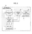
- the information display apparatus 10 includes a setting device 17, a calculating device 20, and a display device 21. Positional information about the disposition of the restricting members is set in the setting device 17.
- the calculating device 20 calculates the warp path numerical information on the basis of the positional information about the restricting members.
- the display device 21 displays the numerical information calculated by the calculating device 20 and/or a diagram based on the numerical information on a screen.
- the setting device 17 includes an input unit 18 for inputting the positional information about the restricting members and a storage unit 19 including a memory for storing the input positional information and the like.
- the input unit 18 may be a dedicated keyboard or may be a touch panel that also functions as a display panel of a display unit 23 of the display device 21, which will be described below.
- the input unit 18 is used not only to input the positional information about the restricting members but also to operate the calculating device 20 and the display device 21.
- positional information about the disposition of the restricting members i.e., the positions of the restricting members in the horizontal direction (front-back direction) and the vertical direction (up-down direction), to be specific, the horizontal distances and the vertical distances from a predetermined reference position (reference surface) to the restricting members are set and stored.
- the reference position in the horizontal direction is the position of the cloth fell 16.
- the reference position in the vertical direction is a horizontal surface passing through the cloth fell 16, i.e., a cloth-fell-side reference surface according to the present invention.
- the cloth-fell-side reference surface which is the reference position in the vertical direction, coincides with the warp line WL.
- the horizontal distance c from the cloth fell 16 to the non-cloth-fell-side restricting portion 13a of the oval tube 13 and the vertical distance s from the warp line WL to the non-cloth-fell-side restricting portion 13a of the oval tube 13 are input.
- Positional information about other restricting members will be described below in detail.
- the positional information about the restricting members which has been input through the input unit 18, is stored in the storage unit 19.
- equations for calculating the shed angle and the path length, which serve as warp path numerical information, and a calculation program for executing the calculation are set and stored in the storage unit 19.
- a display control program that causes the display unit 23 of the display device 21 to display the warp path numerical information, which has been calculated by the calculating device 20, in a predetermined mode as described below is set and stored in the storage unit 19.
- the calculating device 20 loads the calculation program from the storage unit 19 in accordance with a display command signal that is output from the input unit 18 as the input unit 18 is operated; calculates the shed angle and the path length, which serve as warp path numerical information, on the basis of the equations and the positional information about the restricting members, which are stored in the storage unit 19; and outputs the calculation result to a display control unit 22 of the display device 21, which will be described below.
- the display device 21 includes the display unit 23, which includes a liquid crystal panel and the like, and the display control unit 22, which controls the display unit 23.
- the display control unit 22 loads a display control program from the storage unit 19 and displays the calculation result, i.e., the warp path numerical information on the display unit 23 in a predetermined display mode in accordance with the display program.
- the display control unit 22 loads a display control program from the storage unit 19 and displays the calculation result, i.e., the warp path numerical information on the display unit 23 in a predetermined display mode in accordance with the display program.
- Fig. 4 illustrates an example of a display mode for displaying warp path numerical information on the display unit 23.
- a table for displaying warp path numerical information is disposed in an upper part of a screen of the display unit 23.
- a diagram based on the numerical information which represents the paths of the warp yarns 11 when the warp yarns 11 are seen in a side view when the shed is fully open, is disposed.
- warp path numerical information to be displayed in the cells of the table is omitted. The meanings of the terms used in the cells of the table will be described below.
- frame number in the uppermost row refers to the numbers of the heald frames in the order of increasing distance from the cloth fell 16.
- a frame number corresponds to the warp yarns 11 passed through the healds 15 of a corresponding one of the heald frames, i.e., a warp sheet that is shed by the heald frame.
- the table has columns 1 to 20 for "frame number", which means that the table can be used for up to twenty heald frames. Since the loom according to the present embodiment includes eight heald frames as illustrated in Fig. 2 , columns for "frame number" from 1 to 8 are used.
- shed angle refers to the angle between each of the warp yarns 11 and a corresponding reference surface when the shed is fully open, as described above.
- the term "in front of frame” indicates that the shed angle is the shed angle of the warp yarns 11 that are located between the cloth fell 16 and the heald frames, i.e., the healds 15.
- the term "behind frame” indicates that the shed angle is the shed angle of the warp yarns 11 that are located between the heald frames, i.e., the healds 15 and the non-cloth-fell-side restricting portion 13a or the non-cloth-fell-side restricting portion 14a.
- upper yarn indicates that the shed angle is the shed angle of the warp yarns 11 that are moved to the upper shedding position when the shed is opened.
- lower yarn indicates that the shed angle is the shed angle of the warp yarns 11 that are moved to the lower shedding position when the shed is opened.
- warp length refers to the path length of the warp yarns 11.
- upper yarn fully open indicates that the yarn length is the path length of the warp yarns 11 that are moved to the upper shedding position (the shedding position above the warp line) when the shed of the warp yarns 11 is fully opened.
- lower yarn fully open indicates that the yarn length is the path length of the warp yarns 11 that are moved to the lower shedding position (the shedding position below the warp line) when the shed of the warp yarns 11 is fully opened.
- in front of frame indicates that the yarn length is the path length of the warp yarns 11 that are located between the cloth fell 16 and the heald frame, i.e., the healds 15.
- warp frame indicates that the yarn length is the path length of the warp yarns 11 that are located between the heald frame, i.e., the healds 15 and the non-cloth-fell-side restricting portion 13a or the non-cloth-fell-side restricting portion 14a.
- the term "entire path” indicates that the yarn length is the path length of the warp yarns 11 from the cloth fell 16 to the tension roller 12.
- the horizontal distances and the vertical distances from the predetermined reference position (reference surface) to the restricting members are set and stored as positional information about the restricting members.
- the reference position in the horizontal direction is the position of the cloth fell 16
- the reference position in the vertical direction is the position of the cloth-fell-side reference surface.
- the cloth-fell-side reference surface coincides with the warp line WL.
- the horizontal distances from the cloth fell 16 to the restricting members and the vertical distances from the warp line WL to the restricting members are set in the setting device 17 as the positional information about the restricting members. Positional information that is input for each of the restricting members will be described below.
- the alphabet symbols used in the description below correspond to the alphabet symbols in Fig. 2 .
- the horizontal distance from the cloth fell 16 to the first frame is, to be specific, the horizontal distance from the cloth fell 16 to the centers of the mail eyes 24 of the healds 15 of the first frame (positions at which warp yarns are bent).
- the pitch of the heald frames is the same as the pitch of the healds 15, i.e., the pitch of the mail eyes 24.
- Fig. 2 in which the paths of the warp yarns 11 are schematically illustrated, the positions of the mail eyes 24 of the healds 15 in the vertical direction are the same.
- the amounts of shedding of the heald frames i.e., the amounts of displacement of the healds 15 in the up-down direction, generally differ between the heald frames. Therefore, when the amounts of shedding of the heald frames differ from each other, the positional information x and y are input for each of the heald frames.
- the positional information x and y are input as values representing the position in the vertical direction at which each of the warp yarns 11 that is threaded through the mail eye 24 is bent.
- the positional information x and y may be approximated by the vertical distance from the cloth-fell-side reference surface to (the center of) the mail eye 24.
- the positional information x and y may be determined by using set values of the shedding amount for a shedding device (not shown) so as to correspond to the amount of upward displacement and the amount of downward displacement from the positions at which the heald frames are located when the shed is closed (hereinafter also referred to as the "upper shedding amount” and the “lower shedding amount”).
- the positional information x and y correspond to the vertical distance from the warp line WL to (the center of) the mail eye 24.
- the size of the mail eye 24 is larger than the diameter of each of the warp yarn 11, the warp yarn 11, which is threaded through the mail eye 24, becomes displaced in the up-down direction during shedding motion. Therefore, when it is necessary to input the positional information x and y more accurately, it is preferable that the displacement of the warp yarn 11 in the up-down direction in the mail eye 24 be considered. This will be described below with reference to Figs. 6A to 6C .
- the distance d is input on the basis of the position of the tension roller 12 in the horizontal direction when the shed of the warp yarns 11 is fully open. That is, in a general loom, the tension roller 12 may take any of a plurality of positions in the horizontal direction so that the tension roller 12 can perform easing operation so as to suppress variation in the tension of the warp yarns 11 due to shedding motion.
- the distance d is input on the basis of the position of the warp restricting portion 12a of the tension roller 12 when the shed is fully open. However, as necessary, the distance d may be input on the basis of a neutral position of the tension roller 12.
- the distance d may be input on the basis of the middle position.
- the distance d may be input on the basis of the position of the tension roller at which the warp tension when the shed is closed and the force of the easing spring balance with each other.
- the position of the warp restricting portion 12a of the tension roller 12 in the vertical direction is located on the cloth-fell-side reference surface. Therefore, it is not necessary to input vertical positional information about the tension roller 12.
- Fig. 6A is a front view of one of the healds 15, which serves as a restricting member.
- the mail eye 24, which is a through-hole through which the warp yarn 11 is threaded, is formed at substantially the center of the heald 15.
- the mail eye 24 is an elongated hole having a dimension in the longitudinal direction of the heald 15 that is larger than the diameter of the warp yarn 11. Therefore, the warp yarn 11, which is passed through the mail eye 24, is displaceable to some extent in the vertical direction in the mail eye 24.
- the heald 15 is attached to a heald frame (not shown) through heald support members 25 at the upper and lower ends thereof.
- cutouts 26, which are shaped like elongated holes, are formed at the upper and lower ends of the heald 15.
- the cutouts 26 are hooked over the heald support members 25 of the heald frame, and thereby the heald 15 is supported by the heald frame.
- the dimension of each of the heald support members 25 in the longitudinal direction is slightly smaller than the dimension of a corresponding one of the cutouts 26 in the longitudinal direction. Therefore, the heald 15 is supported by the heald frame with a certain amount of play 27 in the up-down direction.
- Fig. 6B illustrates the position of the warp yarn 11 relative to the mail eye 24 when the shed is upwardly open and the position of the heald 15 relative to the heald support members 25, i.e., the heald frame.
- the warp yarn 11 is downwardly displaced in the mail eye 24 and the path of the warp yarn 11 is restricted by the lower end of the mail eye 24.
- Fig. 6C illustrates the position of the warp yarn 11 relative to the mail eye 24 when the shed is downwardly open and the position of the heald 15 relative to the heald support members 25, i.e., the heald frame.
- the warp yarn 11 is upwardly displaced in the mail eye 24 and the path of the warp yarn 11 is restricted by the upper end of the mail eye 24.
- the heald support members 25 are displaced to lower parts of the cutouts 26.
- the position of the warp yarn 11 relative to the mail eye 24 and the position of the heald 15 relative to the heald frame changes depending on whether the heald frame is at the upper shedding position or at the lower shedding position. Therefore, it is preferable that this change be considered when inputting the vertical positional information about the healds 15, which serve as restricting members.
- the vertical positional information about the healds 15 is input by using the amount of shedding, i.e., the amount of displacement of the heald frame, as described above, the positional information x and y of the healds 15 in the vertical direction correspond to the vertical distance from the warp line WL to (the center of) the mail eyes 24.
- the displacement of the warp yarns 11 in the up-down direction in the mail eyes 24 be considered.
- the heald frame When the heald frame is located at the lower shedding position, the positions of the healds 15, i.e., the mail eyes 24, are upwardly displaced by an amount corresponding to the play 27 between the healds 15 and the heald frame as compared with the lower shedding amount. Therefore, when inputting the positional information y by using the amount of shedding, the amount of play between the healds 15 and the heald frame may be set in the setting device 17 beforehand and the positional information y may be corrected by subtracting the amount of play therefrom. However, also in this case, if an error in the warp path numerical information due to the play 27 between the healds 15 and the heald frame is small, such correction may be omitted.
- Figs. 5A to 5C calculation of the warp path numerical information, i.e., the shed angle and the path length, which is performed by the calculating device 20, will be described in detail.
- a state in which the healds 15 of one of the eight heald frames that is nearest to the cloth fell 16, i.e., the healds 15 of the first frame are at the upper shedding position is illustrated as a representative example.
- a calculation method that is used to calculate the shed angle and the path length described below is only an example.
- the shed angle and the path length can also be calculated by using another calculation method.
- the shed angle of the warp yarns 11 that are located between the cloth fell 16 and a heald frame, i.e., between the cloth fell 16 and the healds 15 is, as described above, the angle between each of the warp yarns 11 and a horizontal surface passing through the cloth fell 16 (cloth-fell-side reference surface) when the shed is fully open.
- the shed angle in front of the frame (front upper shed angle) ⁇ FT1 when the shed is upwardly open (the shed angle of upper yarns) and the path length in front of the frame (front upper yarn length) L FT1 when the shed is upwardly open (the path length of upper yarns) are calculated using the following set of equations.
- ⁇ FT ⁇ 1 tan - 1 ⁇ x 1 a 1
- L FT ⁇ 1 a 1 2 + x 1 2
- ⁇ FTn tan - 1 ⁇ x n a n
- ⁇ FBn tan - 1 ⁇ y n a n
- L FTn a n 2 + x n 2
- L FBn a n 2 + y n 2
- a n corresponds to "a horizontal distance from the cloth fell to the healds" according to the present invention.
- x n and y n each correspond to "a vertical distance from the cloth-fell-side reference surface that is a horizontal surface passing through the cloth fell to the mail eyes of the healds when the shed of the warp yarns is fully open” according to the present invention.
- the shed angle of the warp yarns 11 located between a heald frame, i.e., the healds 15 and the non-cloth-fell-side restricting portion 14a of the upper yarn restricting pipe 14 (hereinafter, a position between the heald frame and the non-cloth-fell-side restricting portion will also be simply referred to as a position "at the rear of the frame") is, as described above, the angle between each of the warp yarns 11 and a horizontal surface passing through the non-cloth-fell-side restricting portion 14a (non-cloth-fell-side reference surface) when the shed is fully open.
- the upper yarn restricting pipe 14 and the oval tube 13, which serve as restricting members, are disposed between the heald frames and the tension roller 12. Therefore, when the shed is upwardly open as illustrated in Fig. 5B , a horizontal surface passing through the non-cloth-fell-side restricting portion 14a of the upper yarn restricting pipe 14 is the non-cloth-fell-side reference surface. When the shed is downwardly open (not shown), a horizontal surface passing through the non-cloth-fell-side restricting portion 13a of the oval tube 13 is the non-cloth-fell-side reference surface.
- the shed angle at the rear of the frame (rear upper shed angle) ⁇ RT1 when the shed is upwardly open (upper yarn) and the path length at the rear of the frame (rear upper yarn length) L RT1 when the shed is upwardly open (upper yarn) are calculated using the following set of equations.
- ⁇ RT ⁇ 1 tan - 1 ⁇ x 1 - t b - a 1
- L RT ⁇ 1 b - a 1 2 + x 1 - t 2
- the shed angle at the rear of the frame (rear upper shed angle ⁇ RTn , rear lower shed angle ⁇ RBn ) and the path length at the rear of the frame (rear upper yarn length L RTn , rear lower yarn length L RBn ) for the n-th frame are calculated using the following set of equations.
- c and s are positional information about the oval tube 13, which restricts the warp yarns 11 at the lower shedding position (not shown).
- ⁇ RTn tan - 1 ⁇ x n - t b - a n
- ⁇ RBn tan - 1 ⁇ y n - s c - a n
- L RTn b - a n 2 + x n - t 2
- L RBn c - a n 2 + y n - s 2
- (b - an) and (c - an) correspond to "a horizontal distance from the healds to a non-cloth-fell-side restricting portion that restricts the warp path at a position that is on the non-cloth-fell side of the healds and that is nearest to the healds" according to the present invention.
- (x n - t) and (y n - s) correspond to "a vertical distance from a non-cloth-fell-side reference surface that is a horizontal surface passing through the non-cloth-fell-side restricting portion to mail eyes of the healds when a shed of the warp yarns is fully open". These distances may be directly input to the setting device 17 as the positional information about the restricting members.
- the path length L WT from the warp restricting portion 12a of the tension roller 12 to the non-cloth-fell-side restricting portion 14a of the upper yarn restricting pipe 14 is calculated using the following equation.
- L WT d - b 2 + t 2
- La T ⁇ 1 L FT ⁇ 1 + L RT ⁇ 1 + L WT
- La Tn L FTn + L RTn + L WT
- La Bn L FBn + L RBn + L WB
- L WB d - c 2 + s 2
- (d - b) and (d - c) correspond to "a horizontal distance from the non-cloth-fell-side restricting portion to a warp restricting portion of the warp guide roller" according to the present invention.
- t and s correspond to "a vertical distance from a let-off-side reference surface that is a horizontal surface passing through the warp restricting portion of the warp guide roller to the non-cloth-fell-side restricting portion (non-cloth-fell-side reference surface)" according to the present invention.
- other restricting members i.e., the upper yarn restricting pipe 14 for restricting the paths of upper yarns and the oval tube 13 for restricting the paths of lower yarns are disposed between the tension roller 12, which serves as a warp guide roller, and the healds 15. If another restricting member for restricting the paths of upper yarns is not disposed between the tension roller 12 and the healds 15, the path length L WT is zero. If another restricting member for restricting the paths of lower yarns is not disposed between the tension roller 12 and the healds 15, the path length L WB is zero.
- the shed angle and the path length which have been calculated as described above, are output to the display control unit 22 of the display device 21 and displayed on the display unit 23 in a predetermined display mode, for example, in a mode in which the numerical information and a diagram based on the numerical information are displayed as illustrated in Fig. 4 .
- An operator can accurately grasp the conditions of the paths of the warp yarns 11 by referring to numerical information about the shed angle and the path length displayed on the display unit 23, which has been difficult to perform by visual observation.
- the diagram based on the numerical information the operator can intuitively grasp the dispersion degree of the warp yarns.
- the diagram based on the numerical information may be drawn in such a way that the paths of the warp yarns 11 are exaggerated in order to facilitate understanding of the dispersion degree of the warp yarns.
- the adjusted positional information about the disposition of the restricting member may be input again.
- the vertical positional information t of the upper yarn restricting pipe 14, which has been input may be updated by adding the amount of the vertical movement, and the calculating device 20 may perform recalculation by using the updated positional information t.
- the shed angle and the path length that have been adjusted are displayed on the screen of the display device 21 as the numerical information and the like. Therefore, initial determination as to whether or not the adjustment is appropriate can be performed without carrying out test weaving, and thereby an operation of adjusting the paths of the warp yarns 11 can be performed easily in a short time.
- the present invention is applied to a loom in which the warp line WL is horizontal.
- the present invention is not limited thereto.
- the present invention can be applied to a loom in which the warp line WL is inclined.
- the upper yarn restricting pipe 14, which serves as a restricting member is omitted; and the position of a warp restricting portion 12b of the tension roller 12 is higher than that of the cloth fell 16 and therefore the warp line WL is inclined.
- a second embodiment in which the present invention is applied to the loom illustrated in Fig. 7 , will be described in detail.
- the cloth-fell-side reference surface and the let-off-side reference surface do not coincide with the warp line WL, and the let-off-side reference surface is located at a position higher than that of the cloth-fell-side reference surface in the vertical direction.
- the tension roller 12 is a restricting member that restricts the warp yarns 11 that are moved to the upper shedding position when the shed of the warp yarns 11 is opened at a position nearest to the healds 15; and the oval tube 13 is a restricting member that restricts the warp yarns 11 that are moved to the lower shedding position when the shed of the warp yarns 11 is opened at a position nearest to the healds 15.
- non-cloth-fell-side restricting portions are the following two points: the final contact point (warp restricting portion 12b) between the tension roller 12 and the warp yarns 11 in the feed direction of the warp yarns 11, and the final contact point between the oval tube 13 and the warp yarns 11 in the feed direction of the warp yarns 11.
- there are two non-cloth-fell-side reference surfaces i.e., a horizontal surface passing through the warp restricting portion 12b (non-cloth-fell-side restricting portion) of the tension roller 12 and a horizontal surface passing through the non-cloth-fell-side restricting portion 13a of the oval tube 13.
- the non-cloth-fell-side reference surface passing through the warp restricting portion 12b of the tension roller 12 is the same as a let-off-side reference surface.
- the shed angles front upper shed angle ⁇ FTn , front lower shed angle ⁇ FBn , rear upper shed angle ⁇ RTn , rear lower shed angle ⁇ RBn
- the path lengths front upper yarn length L FTn , front lower yarn length L FBn , rear upper yarn length L RTn , rear lower yarn length L RBn , entire path length L aTn when the shed is upwardly open, and entire path length L aBn when the shed is downwardly open
- ⁇ FTn tan - 1 ⁇ x n a n
- ⁇ FBn tan - 1 ⁇ y n a n
- RTn tan - 1 ⁇ x n - t b - a n
- ⁇ RBn tan - 1 ⁇ y n - s c - a n
- L FTn a n 2 + x n 2
- L FBn a n 2 + y n 2
- L RTn b - a n 2 + x n - t 2
- L RBn c - a n 2 + y n - s 2
- La Tn L FTn + L RTn
- the shed angles and the path lengths are calculated, for example, using the following set of equations, including the case where the upper yarn restricting pipe 14 (horizontal distance b, vertical distance t) is not omitted.
- ⁇ FTn tan - 1 ⁇ x n a n
- ⁇ FBn tan - 1 ⁇ y n a n
- RTn tan - 1 ⁇ x n - t b - a n
- ⁇ RBn tan - 1 ⁇ y n - s c - a n
- L FTn a n 2 + x n 2
- L FBn a n 2 + y n 2
- L RTn b - a n 2 + x n - t 2
- L RBn c - a n 2 + y n - s 2
- La Tn L FTn + L RTn + L WT
- La Bn L FBn + L RBn + L RBn + L WB
- the set of equations (9) is the same as the set of equations (8), which is used to calculate the warp path numerical information in the case where the upper yarn restricting pipe 14 is omitted as illustrated in Figs. 8A and 8B .
- the horizontal positional information about the restricting members is set with reference to the cloth fell.
- another specific reference position may be set and the distances from the reference position to the restricting members may be set.
- the reference surface of the vertical positional information about the restricting members may be a horizontal surface other than the cloth-fell-side reference surface, such as the let-off-side reference surface.
- the distance from the non-cloth-fell-side restricting portion to the centers of the mail eyes of the healds of the heald frame may be set; and regarding the vertical direction, the distance from the non-cloth-fell-side reference surface to the mail eyes of the healds of the heald frame when the shed of warp yarns is fully open may be set.
- the angle between each of the warp yarns and a corresponding horizontal reference surface when the shed of the warp yarns is fully open i.e., the angle between the warp yarn and the cloth-fell-side reference surface at a position in front of the frame and the angle between the warp yarn and the non-cloth-fell-side reference surface at a position at the rear of the frame are calculated as numerical values related to the dispersion degree of the warp yarns.
- the angle between each of the warp yarns and an imaginary vertical surface extending in the longitudinal direction (vertical direction) of the healds of the heald frames (hereinafter referred to as "imaginary vertical reference surface”) may be calculated.
- the imaginary vertical reference surface for the warp yarn 11 at a position in front of the frame is the same as that of the warp yarn 11 at a position at the rear of the frame.
- an imaginary vertical reference surface for all heald frames may be set at each of a position in front of the frame and a position at the rear of the frame.
- an imaginary vertical reference surface ⁇ F for the warp yarns 11 located in front of the frame is set between the cloth fell 16 and one of the heald frames that is nearest to the cloth fell 16 (the first frame)
- an imaginary vertical reference surface ⁇ R for the warp yarns 11 located at the rear of the frame is set between one of the heald frames that is farthest from the cloth fell 16 (the eighth frame in the embodiments described above) and the non-cloth-fell-side restricting portion 14a.
- the angle between each of the warp yarns 11 and a predetermined reference surface is calculated as a numerical value related to the dispersion degree of warp yarns.
- the positions of the intersections of imaginary planes (for example, the imaginary vertical reference surfaces ⁇ F and ⁇ R in Fig. 8B ) that are respectively set between the heald frames and the reference positions (cloth fell 16 and non-cloth-fell-side restricting portion 14a) and the warp yarns 11 in the up-down direction, i.e., the distances H FTn , H RTn , and the like from a horizontal reference surface (cloth-fell-side reference surface) to the intersections may be calculated ( Fig. 9A ).
- the cloth-fell-side reference surface coincides with the warp line WL.
- the imaginary planes are set so as to extend in the up-down direction and extend parallel to the heald frames with respect to the width direction of the heald frames.
- the imaginary planes need not be the planes extending vertically in the up-down direction as illustrated in Fig. 9A as long as the imaginary planes extend parallel to the heald frames with respect to the width direction.
- Planes ⁇ F and ⁇ R illustrated in Fig. 9B which are inclined with respect to a horizontal surface in a side view of the warp shed, may be used as the imaginary planes.
- the distances H FTn and H RTn from the horizontal reference surface may be calculated.
- the distance H FTn , and H RTn , from a reference surface in a direction in which the imaginary planes extend in the up-down direction may be calculated.
- Warp path numerical information to be obtained need not be that when the shed of warp yarns is fully open.
- Warp path numerical information for another specific main shaft rotation angle may be obtained.
- positional information about the restricting members (members that influence the warp path) that are necessary for the specific main shaft rotation angle be set and stored in the storage unit 19.
- the shed angle and the path length of warp yarns when the shed is fully open are calculated as warp path numerical information. Instead of calculating both of these, the case of calculating only one of these is included in the scope of the present invention.
- both of the numerical information and the diagram based on the numerical information are displayed. Alternatively, only one of them may be displayed.
Landscapes
- Engineering & Computer Science (AREA)
- Textile Engineering (AREA)
- Looms (AREA)
- Knitting Machines (AREA)
Abstract
Description
- The present invention relates to an information display apparatus for a loom. In particular, the invention relates to an information display apparatus for a loom that at least includes, as a plurality of members that influence a warp path, a warp guide roller and healds attached to each of a plurality of heald frames, and in which warp yarns that are let off from a warp beam are redirected toward a cloth fell by the warp guide roller, passed through the healds of corresponding ones of the heald frames, and guided to the cloth fell.
- As illustrated in
Fig. 1 , in a general loom,warp yarns 101 are let off from awarp beam 102 around which thewarp yarns 101 are wound, fed over a plurality ofguide rollers 103 for guiding the warp yarns 101 (including a tension roller 105 that detects the warp tension with atension sensor 104, the same applying hereinafter), and redirected toward a cloth fell 106. Subsequently, thewarp yarns 101 are guided through adropper device 107, which is a warp yarn breakage detection device for detecting warp yarn breakage, are passed throughhealds 109 of a plurality ofheald frames 108 that are arranged, and reach the cloth fell 106. Due to vertical motion (shedding motion) of the heald frames 108 (healds 109), a shed is formed by thewarp yarns 101. Aweft yarn 110 is inserted into the shed and beaten up toward the cloth fell 106 by areed 111 so as to be weaved into thewarp yarns 101, and thereby afabric 112 is formed. Thefabric 112, which has been woven in this way, passes over asurface roller 113 and the like and is taken up by a take-up roller 114. - In general, the path of the warp yarns 101 (hereinafter simply referred to as the "warp path" in the present application) from one of the
guide rollers 103 that is located nearest to the healds 109 (hereinafter referred to as a "warp guide roller", which corresponds to the tension roller 105 in the example illustrated inFig. 1 ) to the cloth fell 106 is adjusted in a pre-weaving operation that is performed before weaving is started in accordance with weaving conditions (such as the types of thewarp yarns 101 and theweft yarn 110, and set tension and the like of the warp yarns 101). Since the warp path changes due to shedding motion of thewarp yarns 101, one or both of the warp path that exists when the shed is closed and the warp path that exists when the shed is open is/are adjusted. - The warp path is determined in accordance with the positional relationship between the cloth fell 106 and a plurality of members that exist on the warp path and that influence the warp path, such as the tension roller 105, the
dropper device 107, thehealds 109 of theheald frames 108, and the like. Therefore, the aforementioned adjustment is performed by adjusting the position of at least one of the plurality of members that influence the warp path. To be specific, the adjustment is performed by changing the position of the tension roller 105 or by adjusting the amount of shedding of theheald frames 108 for causing thehealds 109 to perform shedding motion. - An existing device for such adjustment is disclosed in, for example, Japanese Unexamined Patent Application Publication No.
6-10240 Patent Document 1"). With the device described inPatent Document 1, the warp path is adjusted by adjusting the position of a support arm for supporting a guide roller, which serves as a member that influences the warp path, in the height direction by using an adjustment screw. - When an operator adjusts the position of a member that influences a warp path in order to adjust the warp path by using the device described in
Patent Document 1 or the like, whether or not the adjustment is appropriate can be determined only by actually performing test weaving after the adjustment has been made and seeing if weaving is performed in desirable conditions. Thus, at present, the amount of adjustment to be performed depends on the experience and intuition of an operator. That is, the conditions of the warp path that influence weaving include, for example, the length of the warp path and the shed angle of warp yarns when the shed is open. However, even when the loom is jogged after adjusting the positions of the aforementioned members so as to shed warp yarns, it is difficult for an operator to accurately determine whether or not the conditions are appropriate for weaving from visual observation. Thus, at present, it is necessary to actually perform test weaving to determine whether or not the adjustment is appropriate. Therefore, in an existing adjustment operation, an initial adjustment is first performed on the basis of the experience and intuition of an operator, and then test weaving is performed to determine whether or not further adjustment is necessary, and readjustment is performed if necessary. It takes time and effort to perform such an adjustment operation, which involves trial and error. - The length of the warp path, which is one of the conditions of the warp path that influence weaving, is the largest and accordingly the warp tension is the highest when the shed is open. Therefore, when the warp path is adjusted and the warp tension becomes excessively high when the shed is open, the warp yarns are over-tensioned during weaving, whereby the quality of a fabric may decrease and warp yarn breakage may frequently occur depending on the circumstances. However, it is difficult to measure the warp tension by visual observation even when the shed of warp yarns is opened in a pre-weaving operation of the loom. As described above, it is necessary to perform test weaving to determine whether or not the warp tension is appropriate.
- Regarding the shed angle of warp yarns when the shed is open, if the warp yarns are yarns that tend to become fuzzy, such as spun yarns or the like, it is desirable that the warp paths (the shed angle of warp yarns when the shed is fully open) be adjusted so that they are not aligned with one another in a side view when the shed is fully open, i.e., so that they are dispersed vertically to some extent when the shed is fully open. This is because, in the case where the shedding curve has a dwell angle so that the state of the shed of warp warns can be maintained when the shed is fully open during weaving, if the warp paths are excessively aligned with one another, fuzz of the warp yarns may become entangled, and thereby a shedding error may occur and warp yarn breakage may occur depending on the circumstances. However, if the degree of dispersion of warp yarns (hereinafter referred to as the "dispersion degree") is too large, a large difference in the warp tension may occur between the heald frames and may negatively influence weaving. Thus, in practice, it is necessary that the warp paths be dispersed to a level that is difficult to determine by visual observation. Therefore, as with the case described above, whether or not the dispersion degree is appropriate cannot be determined by visual observation even when the shed of warp yarns is opened in a pre-weaving operation, and it is necessary to perform test weaving as described above.
- As heretofore described, it is not efficient to adjust the warp path only on the basis of the experience and intuition of an operator without any reference data. In particular, when adjusting the warp path when the shed is open, it is very difficult for an inexperienced operator to make the warp path be dispersed while considering the warp tension.
- An object of the present invention is to display numerical information and the like regarding the warp path, which serves as reference data for adjusting the warp path, to enable an operator to accurately grasp the path length of warp yarns and the shed angle and the like of warp yarns when the shed is open, which indicate the conditions of the warp path, and thereby enable the operator to perform an operation of adjusting the warp path in a short time.
- To achieve the object described above, an information display apparatus for a loom according to the present invention is configured as follows. According to the present invention, there is provided an information display apparatus for a loom, the loom at least including, as a plurality of members that influence a warp path, a warp guide roller and healds attached to each of a plurality of heald frames, in which loom warp yarns that are let off from a warp beam are redirected toward a cloth fell by the warp guide roller, passed through the healds of corresponding ones of the plurality of heald frames, and guided to the cloth fell, the information display apparatus including a setting device in which positional information about a disposition of the plurality of members is set; a calculating device that calculates numerical information about the warp path on the basis of the positional information; and a display device that displays the numerical information calculated by the calculating device and/or a diagram based on the numerical information on a screen.
- Here, the phrase "a plurality of members that influence a warp path" refers to members that restrict the positions of the warp yarns in the up-down direction (hereinafter "a plurality of members that influence a warp path" are also referred to as "restricting members"). The restricting members are not limited to the warp guide roller and the healds of the heald frames of a shedding device, which are described above. For example, if the loom is provided with a warp breakage detection device (dropper device), the restricting members may include a member of the warp breakage detection device that restricts the position of a warp yarn. The restricting members may include another restricting member that may be provided in the loom.
- The term "warp guide roller" refers to one of a plurality of guide rollers that guides the warp yarns and that is located nearest to the healds. The plurality of guide rollers include a tension roller for detecting the warp tension.
- The term "a disposition of the plurality of members" refers to the positions of the members with respect to the horizontal direction (front-back direction) and the vertical direction (up-down direction). As the positional information, the distances from a predetermined reference position (reference surface) to the restricting members are set in the setting device. The positions of the members are not the positions of the entireties of the members and the positions of the entireties devices including the members. For example, if a restricting member is a heald, the position of the restricting member is the position of a mail eye of the heald through which a warp yarn is threaded. If a restricting member is an oval tube of a dropper device, the position of the restricting member is the position of a contact point between the oval tube and a warp yarn. A mail eye of a heald is a through hole formed in the heald through which a warp yarn is threaded. For a movable member such as a heald, the positional information set in the setting device may be the positions of the heald corresponding to arbitrary main shaft rotation angles (crank angles), such as that when the shed of warp yarns is fully open and the position of the heald when the shed is closed. The position of the heald for only a specific crank angle may be set.
- In the present invention, the term "warp yarns" refers to, strictly speaking, a "warp sheet". A large number of warp yarns that are let off from a warp beam are divided into sheet-shaped groups for corresponding heald frames, and the sheet-shaped groups of warp yarns, i.e., warp sheets are passed through the healds of the corresponding heald frames. Since the paths of the warp yarns included in a warp sheet that is passed through the healds of the same heald frame are the same, the meaning of a warp path is the same as that of the path of a warp sheet in the present invention.
- The calculating device may calculate for each heald frame on the basis of the positional information, as the numerical information, a numerical value related to a dispersion degree of the warp yarns located on a cloth-fell side of the heald frame by using a horizontal distance from the cloth fell to the healds of the heald frame and a vertical distance from a cloth-fell-side reference surface that is a horizontal surface passing through the cloth fell to mail eyes of the healds when a shed of the warp yarns is fully open.
- Here, the phrase "a numerical value related to a dispersion degree of the warp yarns located on the cloth-fell side of the heald frame" may refer to, for example, the angle between the warp yarns and a predetermined reference surface (horizontal surface) (see
Fig. 5A ) or the angle between the warp yarns and an imaginary vertical surface parallel to the healds (seeFigs. 8A and 8B ), the warp yarns being located on the cloth-fell side of the heald frame (the cloth-fell side of the healds through which the warp yarns are threaded in a side view of the warp paths, the same applying hereinafter). Alternatively, the numerical value may be the position of the intersection of the warp yarns and an imaginary surface extending in the up-down direction at a specific position between the heald frame and the cloth fell (seeFigs. 9A and 9B ). - The calculating device may calculate for each heald frame on the basis of the positional information, as the numerical information, a numerical value related to a dispersion degree of the warp yarns located on a non-cloth-fell side of the heald frame by using a horizontal distance from the healds of the heald frame to a non-cloth-fell-side restricting portion that restricts the warp path at a position that is on the non-cloth-fell side of the healds and that is nearest to the healds and a vertical distance from a non-cloth-fell-side reference surface that is a horizontal surface passing through the non-cloth-fell-side restricting portion to mail eyes of the healds when a shed of the warp yarns is fully open.
- Here, the term "a non-cloth-fell-side restricting portion" refers to a final contact point, in the feed direction of the warp yarns, between the warp yarns and a restricting member that restricts the warp path at a position that is nearest to the healds and that is on the non-cloth-fell side of the heald frame (on the side of the healds, through which the warp yarns are threaded, on which the warp guide roller is located in a side view of the warp path, the same applying hereinafter).
- On the cloth-fell side of the heald frame, another restricting member does not exist between the cloth fell and the healds serving as restricting members. On the non-cloth-fell side heald frame, another restricting member, such as a warp restricting pipe, a restricting member included in a warp yarn breakage detection device, or the like, may be disposed between the heald frame and the warp guide roller serving as a restricting member. For example, if a warp yarn breakage detection device is disposed between the heald frame and the warp guide roller and a restricting member of the warp yarn breakage detection device restricts the warp path when the shed is opened, a part of the restricting member serves as a non-cloth-fell-side restricting portion. On the other hand, if another restricting member is not disposed between the warp guide roller and the healds, a part of the warp guide roller serves as a non-cloth-fell-side restricting portion.
- During shedding, the warp yarns are divided into two groups, one of which is moved to the upper shedding position and the other of which is moved to the lower shedding position. There exists a restricting member that restricts the path of only one of these groups. For example, if the warp yarn breakage detection device is a dropper device, an oval tube of the dropper device, which serves as a restricting member, restricts only the path of warp yarns that are moved to the lower shedding position and does not restrict the path of warp yarns that are moved to the upper shedding position. Therefore, when only the dropper device exists between the heald frame and the warp guide roller (for example, see
Fig. 7 ), a non-cloth-fell-side restricting portion for the warp yarns at the lower shedding position is a part of the oval tube and a non-cloth-fell-side restricting portion for the warp yarns at the upper shedding position is a part of the warp guide roller. In this case, there exist two non-cloth-fell-side restricting portions and there exist two non-cloth-fell-side reference surfaces that pass through the non-cloth-fell-side restricting portions. - The phrase "a numerical value related to a dispersion degree of the warp yarns located on a non-cloth-fell side of the heald frame" refers to, for example, the angle between each of the warp yarns and a predetermined reference surface (horizontal surface) on the non-cloth-fell side of the heald frame (see
Fig. 5B ), the angle between each of the warp yarns and an imaginary vertical surface extending parallel to the healds on the non-cloth-fell side of the heald frame (seeFigs. 8A and 8B ), or the like. The numerical value may be the position, in the up-down direction, of an intersection of each of the warp yarns and an imaginary surface extending in the up-down direction at a specific position between the heald frame and the non-cloth-fell-side restricting portion (seeFigs. 9A and 9B ). - The calculating device calculate for each heald frame on the basis of the positional information, as the numerical information, a path length from the warp guide roller to the cloth fell when a shed of the warp yarns is fully open by using the following distance information:
- a horizontal distance from the cloth fell to the healds of the heald frame,
- a vertical distance from the cloth-fell-side reference surface to mail eyes of the healds of the heald frame when the shed of the warp yarns is fully open,
- a horizontal distance from the healds of the heald frame to the non-cloth-fell-side restricting portion,
- a vertical distance from the non-cloth-fell-side reference surface to the mail eyes of the healds of the heald frame when the shed of warp yarns is fully open,
- a horizontal distance from the non-cloth-fell-side restricting portion to a warp restricting portion of the warp guide roller, and
- a vertical distance from a let-off-side reference surface that is a horizontal surface passing through the warp restricting portion of the warp guide roller to the non-cloth-fell-side restricting portion (non-cloth-fell-side reference surface).
- Here, the phrase "a warp restricting portion of the warp guide roller" refers to the final contact point between the warp guide roller and the warp yarns in the feed direction of the warp yarns.
- As described above, if another restricting member is not disposed between the warp guide roller and the healds, the warp restricting portion of the warp guide roller serves as a non-cloth-fell-side restricting portion. Therefore, in this case, "a horizontal distance from the non-cloth-fell-side restricting portion to a warp restricting portion of the warp guide roller" and "a vertical distance from the let-off-side reference surface that is a horizontal surface passing through the warp restricting portion of the warp guide roller to the non-cloth-fell-side restricting portion (non-cloth-fell-side reference surface)" are zero.
- If the position of the cloth fell in the vertical direction is the same as that of the warp restricting portion of the warp guide roller and therefore the warp line (a line connecting the cloth fell to the warp restricting portion of the warp guide roller, the same applying hereinafter) is horizontal, the cloth-fell-side reference surface and the let-off-side reference surface both coincide with the warp line (for example, see
Fig. 2 ). However, in some looms, the position of the warp restricting portion of the warp guide roller is higher than that of the cloth fell, and therefore the warp line is inclined (for example, seeFig. 7 ). In this case, the cloth-fell-side reference surface and the let-off-side reference surface do not coincide with the warp line, and the position of the let-off-side reference surface in the vertical direction is higher than that of the cloth-fell-side reference surface. - The display device may display the numerical information and/or the diagram based on the numerical information for at least two of the heald frames simultaneously on a single screen.
- With the present invention, numerical information about the warp path is calculated on the basis of positional information about the disposition of a plurality of members that influence the warp path, and the calculated numerical information is displayed on a screen of a display device as the numerical information and/or a diagram based on the numerical information. Therefore, by looking at the display, an operator can accurately grasp the conditions of the warp path that influence weaving as numerical information or the like, which has been difficult to perform by visual observation. Thus, in contrast to existing technologies, with which whether or not the conditions of the warp path are appropriate for weaving cannot be determined without performing test weaving, with the present invention, whether or not the conditions of the warp path are appropriate for weaving can be determined by using the numerical information and the like displayed on the display unit as reference data without performing test weaving. If the position of one of the members that influence the warp path is mechanically adjusted, by updating the positional information about the disposition of the member, the conditions of the warp path after the adjustment are displayed as numerical information and the like on a screen of the display device. Therefore, initial determination as to whether or not the adjustment is appropriate can be performed without carrying out test weaving, and thereby an operation of adjusting the warp path can be performed easily in a short time.
- Since the conditions of the warp path are represented as numerical information, by building a database of the numerical information in association with the evaluation of weaving and problems that occurred during weaving performed under the conditions, adjustment of the warp path performed in a pre-weaving operation can be performed more easily and appropriately.
- Numerical values related to the dispersion degree of warp yarns located on the cloth-fell side of the heald frames are calculated for each of the heald frames as numerical information about the warp path, and they are displayed on a screen of a display device as numerical information and/or a diagram based on the numerical information. Therefore, by looking at the display, an operator can accurately grasp the dispersion degree of the warp yarns located on the cloth-fell side of the heald frames as numerical information and the like, which has been difficult to perform by visual observation. Thus, in particular, when spun yarns and the like, which tend to become fuzzy, are used as the warp yarns, by using eth numerical information and the like as reference data, an operator can make the warp paths be dispersed to a level at which a large difference in the warp tension does not occur between the heald frames, i.e., to a level that is difficult to determine by visual observation. Accordingly, entanglement of fuzz of the warp yarns, shedding failure, and warp yarn breakage, which may occur when the warp paths are excessively aligned with one another, can be prevented without negatively influencing weaving. If the position of one of the members that influences the warp path is mechanically adjusted, by updating the positional information about the disposition of the member, the dispersion degree of warp yarns after the adjustment is displayed as numerical information and the like on a screen of the display device. Therefore, initial determination as to whether or not the adjustment is appropriate can be performed without carrying out test weaving, and thereby an operation of adjusting the dispersion degree of warp yarns can be performed easily in a short time.
- Numerical values related to the dispersion degree of warp yarns located on the non-cloth-fell side of the heald frames are calculated for each of the heald frames as numerical information about the warp path and displayed on a screen of a display device as numerical information and/or a diagram based on the numerical information. Therefore, by looking at the display, an operator can accurately grasp the dispersion degree of the warp yarns located on the non-cloth-fell side of the heald frames as numerical information and the like, which has been difficult to perform by visual observation. Thus, the advantageous effect the same as described above can be obtained.
- The path length of warp yarns from the warp guide roller to the cloth fell when the shed of warp yarns is fully open is calculated for each of the heald frames as numerical information about the warp path and displayed on a screen of a display device as numerical information and/or a diagram based on the numerical information. Therefore, by looking at the display, an operator can accurately grasp the path length of warp yarns as numerical information and the like, which has been difficult to perform by visual observation. Thus, the operator can determine whether or not the path length of warp yarns is appropriate for weaving by using the numerical information and the like displayed on the display device as reference data. If the position of a member that influences the warp path is mechanically adjusted, by updating the positional information about the disposition of the member, the length of the warp path after the adjustment is displayed as numerical information and the like on a screen of the display device. Therefore, initial determination as to whether or not the adjustment is appropriate can be performed without carrying out test weaving, and thereby an operation of adjusting the path length of warp yarns can be performed easily in a short time.
- By displaying the numerical information and/or the diagram based on numerical information for at least two of the heald frames simultaneously on a single screen, the numerical information and the like calculated for each of the heald frames can be compared with each other at a glance, and thereby the warp paths can be easily made dispersed.
-
-
Fig. 1 schematically illustrates a loom for which the present invention is used; -
Fig. 2 illustrates the warp path according to a first embodiment of the present invention; -
Fig. 3 is a block diagram illustrating the structure of an information display apparatus; -
Fig. 4 illustrates an example of a display screen of the information display apparatus; -
Figs. 5A to 5C are partial enlarged views of the warp path illustrated inFig. 2 ,Fig. 5A illustrating a path on the cloth-fell side of a heald frame,Fig. 5B illustrating a path on the non-cloth-fell side of the heald frame, andFig. 5C illustrating a path from a non-cloth-fell-side restricting portion to a tension roller; -
Figs. 6A to 6C are front views illustrating the positional relationship among a heald frame, a heald, and a warp yarn;Fig. 6A illustrating a state when the shed is closed,Fig. 6B illustrating a state when the shed is upwardly open; andFig. 6C illustrating a state when the shed is downwardly open; -
Fig. 7 illustrates the warp path according to a second embodiment of the present invention; -
Figs. 8A and 8B illustrate the shed angle according to a modification of the present invention; and -
Figs. 9A and 9B illustrate the numerical values related to the dispersion degree of warp yarns according to a modification of the present invention. - Hereinafter, a first embodiment of the present invention will be described with reference to
Figs. 2 to 6C . -
Fig. 2 illustrates the paths ofwarp yarns 11 when the shed is open in a loom for which aninformation display apparatus 10 according to the present invention is used. The loom according to the present embodiment includes a plurality of members that influence the paths of thewarp yarns 11, i.e., restricting members as follows: atension roller 12 serving as a warp guide roller, an oval tube 13 (also referred to as a lower yarn restricting pipe) of a dropper device that is a warp yarn breakage detection device, an upperyarn restricting pipe 14 that restricts upward motion of thewarp yarns 11 when thewarp yarns 11 are shed, andhealds 15 attached to eight heald frames (not shown). InFig. 2 , regarding the components of the dropper device, only theoval tube 13 is illustrated and other components of the dropper device are omitted. Thehealds 15 are illustrated by alternate long and short dash lines passing through the centers ofmail eyes 24 of the healds 15 (the positions at which thewarp yarns 11 are bent) in the front-back direction. The heald frames, which support thehealds 15, are not illustrated. The positions of the restricting members can be adjusted by using adjustment means (not shown) with respect to the horizontal direction (front-back direction) and the vertical direction (up-down direction) of the restricting members. - The upper
yarn restricting pipe 14 and theoval tube 13 are disposed between the heald frames, i.e., thehealds 15 and thetension roller 12. The upperyarn restricting pipe 14 is a restricting member that restricts thewarp yarns 11 that are moved to an upper shedding position when the shed is opened at a position that is on the non-cloth-fell side of the heald frames and that is nearest to the healds 15. Theoval tube 13 is a restricting member that restricts thewarp yarns 11 that are moved to an upper shedding position when the shed is opened at a position that is on the non-cloth-fell side of the heald frames and that is nearest to the healds 15. Therefore, in the present embodiment, there exist two non-cloth-fell-side restricting portions according to the present invention. One of the non-cloth-fell-side restricting portions, which restricts thewarp yarns 11 that are moved to the upper shedding position, is a part of the upperyarn restricting pipe 14. The other of the non-cloth-fell-side restricting portions, which restricts thewarp yarns 11 that are moved to the lower shedding position, is a part of theoval tube 13. To be specific, two points, i.e., the final contact point between the upperyarn restricting pipe 14 and thewarp yarns 11 in the feed direction of thewarp yarns 11 and the finial contact point between theoval tube 13 and thewarp yarns 11 in the feed direction of thewarp yarns 11 are respectively non-cloth-fell-side restricting portions side restricting portion 13a of theoval tube 13 and a horizontal surface passing through the non-cloth-fell-side restricting portion 14a of the upperyarn restricting pipe 14 are non-cloth-fell-side reference surfaces according to the present embodiment. - In the present embodiment, numerical information about the warp path according to the present invention (hereinafter referred to as "warp path numerical information") is calculated for each of warp sheets (hereinafter simply referred to as "warp yarns") corresponding to the eight heald frames. The warp path numerical information calculated in the present embodiment includes the following two items: the angle between each of the
warp yarns 11 and a corresponding reference surface when the shed is fully open (hereinafter also referred to as the "shed angle"), and the path length of each of thewarp yarns 11 from thetension roller 12 to a cloth fell 16 when the shed is fully open (hereinafter also simply referred to as the "path length"). - Here, the shed angle, which corresponds to a numerical value related to a dispersion degree of the warp yarns according to the present invention, serves as an indicator of the dispersion degree of the
warp yarns 11 in the up-down direction when the shed is fully open. In the present embodiment, on the cloth-fell side of the heald frames, i.e., thehealds 15, a horizontal surface passing through the cloth fell 16, i.e., a cloth-fell-side reference surface according to the present invention is the reference surface for the shed angle. On the non-cloth-fell side of the heald frames, horizontal surfaces passing through the two non-cloth-fell-side restricting portions Fig. 2 , there are four shed angles corresponding to the combinations of in front of/behind the heald frames and upper/lower shed positions of warp yarns: a front upper shed angle θFTn, a front lower shed angle θFBn, a rear upper shed angle θRTn, and a rear lower shed angle θRBn. These angles are calculated for each of the heald frames. The index n attached the symbols of the shed angles represents the "frame number" of the eight heald frames. In the present embodiment, the heald frames are indexed by 1 to 8 in the order of increasing distance from the cloth fell 16. - Besides the structure illustrated in
Fig. 2 , the structure of the loom is the same as that of a general loom described in "Description of the Related Art", which is illustrated inFig. 1 . Therefore, description of such structure will be omitted. In the present embodiment, an input setting device (not shown) disposed on the loom also functions as theinformation display apparatus 10 according to the present invention. The input setting device includes, for example, a touch panel for performing various settings of the loom. However, theinformation display apparatus 10 according to the present invention may be a device that is independent from the loom, such as a personal computer or the like in which a software for executing the function of the present invention is installed. - In the loom used as an example in the present embodiment, a warp line WL, which is a line connecting a
warp restricting portion 12a of the tension roller 12 (the final contact point between thewarp yarns 11 and thetension roller 12 in the warp feed direction) and the cloth fell 16, is horizontal. However, as in another embodiment illustrated inFig. 7 , the present invention is also applicable to a loom in which the warp line WL is inclined. - Next, referring to
Fig. 3 , theinformation display apparatus 10 according to the present invention will be described. Theinformation display apparatus 10 includes asetting device 17, a calculatingdevice 20, and adisplay device 21. Positional information about the disposition of the restricting members is set in thesetting device 17. The calculatingdevice 20 calculates the warp path numerical information on the basis of the positional information about the restricting members. Thedisplay device 21 displays the numerical information calculated by the calculatingdevice 20 and/or a diagram based on the numerical information on a screen. - The
setting device 17 includes aninput unit 18 for inputting the positional information about the restricting members and astorage unit 19 including a memory for storing the input positional information and the like. Theinput unit 18 may be a dedicated keyboard or may be a touch panel that also functions as a display panel of adisplay unit 23 of thedisplay device 21, which will be described below. Theinput unit 18 is used not only to input the positional information about the restricting members but also to operate the calculatingdevice 20 and thedisplay device 21. - In the
storage unit 19, positional information about the disposition of the restricting members, i.e., the positions of the restricting members in the horizontal direction (front-back direction) and the vertical direction (up-down direction), to be specific, the horizontal distances and the vertical distances from a predetermined reference position (reference surface) to the restricting members are set and stored. In the present embodiment, as illustrated inFig. 2 , the reference position in the horizontal direction is the position of the cloth fell 16. The reference position in the vertical direction is a horizontal surface passing through the cloth fell 16, i.e., a cloth-fell-side reference surface according to the present invention. However, as described above, since the warp line WL of the loom according to the present embodiment is horizontal, the cloth-fell-side reference surface, which is the reference position in the vertical direction, coincides with the warp line WL. For example, as the positional information about theoval tube 13, the horizontal distance c from the cloth fell 16 to the non-cloth-fell-side restricting portion 13a of theoval tube 13 and the vertical distance s from the warp line WL to the non-cloth-fell-side restricting portion 13a of theoval tube 13 are input. Positional information about other restricting members will be described below in detail. - As illustrated in
Fig. 3 , the positional information about the restricting members, which has been input through theinput unit 18, is stored in thestorage unit 19. In addition to the positional information about the restricting members, equations for calculating the shed angle and the path length, which serve as warp path numerical information, and a calculation program for executing the calculation are set and stored in thestorage unit 19. Moreover, a display control program that causes thedisplay unit 23 of thedisplay device 21 to display the warp path numerical information, which has been calculated by the calculatingdevice 20, in a predetermined mode as described below is set and stored in thestorage unit 19. - The calculating
device 20 loads the calculation program from thestorage unit 19 in accordance with a display command signal that is output from theinput unit 18 as theinput unit 18 is operated; calculates the shed angle and the path length, which serve as warp path numerical information, on the basis of the equations and the positional information about the restricting members, which are stored in thestorage unit 19; and outputs the calculation result to adisplay control unit 22 of thedisplay device 21, which will be described below. - The
display device 21 includes thedisplay unit 23, which includes a liquid crystal panel and the like, and thedisplay control unit 22, which controls thedisplay unit 23. When receiving a calculation result from the calculatingdevice 20, thedisplay control unit 22 loads a display control program from thestorage unit 19 and displays the calculation result, i.e., the warp path numerical information on thedisplay unit 23 in a predetermined display mode in accordance with the display program. There are the following three display modes: a display mode in which the calculation result is displayed as numerical information, a display mode in which the calculation result is displayed as a diagram based on the calculation result, and a display mode in which the numerical information and the diagram are displayed on the same screen. -
Fig. 4 illustrates an example of a display mode for displaying warp path numerical information on thedisplay unit 23. In this example, a table for displaying warp path numerical information is disposed in an upper part of a screen of thedisplay unit 23. In a lower part of the screen, a diagram based on the numerical information, which represents the paths of thewarp yarns 11 when thewarp yarns 11 are seen in a side view when the shed is fully open, is disposed. However, inFig. 4 , warp path numerical information to be displayed in the cells of the table is omitted. The meanings of the terms used in the cells of the table will be described below. - The term "frame number" in the uppermost row refers to the numbers of the heald frames in the order of increasing distance from the cloth fell 16. A frame number corresponds to the
warp yarns 11 passed through thehealds 15 of a corresponding one of the heald frames, i.e., a warp sheet that is shed by the heald frame. In the example illustrated inFig. 4 , the table hascolumns 1 to 20 for "frame number", which means that the table can be used for up to twenty heald frames. Since the loom according to the present embodiment includes eight heald frames as illustrated inFig. 2 , columns for "frame number" from 1 to 8 are used. - The term "shed angle" refers to the angle between each of the
warp yarns 11 and a corresponding reference surface when the shed is fully open, as described above. - The term "in front of frame" indicates that the shed angle is the shed angle of the
warp yarns 11 that are located between the cloth fell 16 and the heald frames, i.e., the healds 15. - The term "behind frame" indicates that the shed angle is the shed angle of the
warp yarns 11 that are located between the heald frames, i.e., thehealds 15 and the non-cloth-fell-side restricting portion 13a or the non-cloth-fell-side restricting portion 14a. - The term "upper yarn" indicates that the shed angle is the shed angle of the
warp yarns 11 that are moved to the upper shedding position when the shed is opened. - The term "lower yarn" indicates that the shed angle is the shed angle of the
warp yarns 11 that are moved to the lower shedding position when the shed is opened. - The term "yarn length" refers to the path length of the
warp yarns 11. - The term "upper yarn fully open" indicates that the yarn length is the path length of the
warp yarns 11 that are moved to the upper shedding position (the shedding position above the warp line) when the shed of thewarp yarns 11 is fully opened. - The term "lower yarn fully open" indicates that the yarn length is the path length of the
warp yarns 11 that are moved to the lower shedding position (the shedding position below the warp line) when the shed of thewarp yarns 11 is fully opened. - The term "in front of frame" indicates that the yarn length is the path length of the
warp yarns 11 that are located between the cloth fell 16 and the heald frame, i.e., the healds 15. - The term "behind frame" indicates that the yarn length is the path length of the
warp yarns 11 that are located between the heald frame, i.e., thehealds 15 and the non-cloth-fell-side restricting portion 13a or the non-cloth-fell-side restricting portion 14a. - The term "entire path" indicates that the yarn length is the path length of the
warp yarns 11 from the cloth fell 16 to thetension roller 12. - Next, referring to
Fig. 2 , positional information about the restricting members, which is input through theinput unit 18 of thesetting device 17 and stored in thestorage unit 19 of thesetting device 17, will be described. As described above, in the present embodiment, the horizontal distances and the vertical distances from the predetermined reference position (reference surface) to the restricting members are set and stored as positional information about the restricting members. Here, the reference position in the horizontal direction is the position of the cloth fell 16, and the reference position in the vertical direction is the position of the cloth-fell-side reference surface. In the present embodiment, the cloth-fell-side reference surface coincides with the warp line WL. Therefore, the horizontal distances from the cloth fell 16 to the restricting members and the vertical distances from the warp line WL to the restricting members are set in thesetting device 17 as the positional information about the restricting members. Positional information that is input for each of the restricting members will be described below. The alphabet symbols used in the description below correspond to the alphabet symbols inFig. 2 . - Regarding the
healds 15 of the heald frames, the following two items of horizontal positional information are input: - a1: the horizontal distance from the cloth fell 16 to the heald frame nearest to the cloth fell 16 (hereinafter also referred to as the "first frame"), and
- p: the pitch of the heald frames (the distance between adjacent heald frames).
- Here, the horizontal distance from the cloth fell 16 to the first frame is, to be specific, the horizontal distance from the cloth fell 16 to the centers of the
mail eyes 24 of thehealds 15 of the first frame (positions at which warp yarns are bent). - The pitch of the heald frames is the same as the pitch of the
healds 15, i.e., the pitch of themail eyes 24. When the "frame number" of a heald frame is denoted by n (n = 1, 2, ..., 8), the horizontal positional information an of thehealds 15 of each of the heald frames can be calculated from the values of a1 and p by using the following equation.
- Regarding the
healds 15 of the heald frames, the following two items of vertical positional information are input: - x: the vertical distance (absolute value) from the cloth-fell-side reference surface (warp line WL) to the
mail eyes 24 of thehealds 15 that are located at the upper shedding position when the shed of warp yarns is fully open, and - y: the vertical distance (absolute value) from the cloth-fell-side reference surface (warp line WL) to the
mail eyes 24 of thehealds 15 that are located at the lower shedding position when the shed of warp yarns is fully open. - In
Fig. 2 , in which the paths of thewarp yarns 11 are schematically illustrated, the positions of themail eyes 24 of thehealds 15 in the vertical direction are the same. In reality, however, the amounts of shedding of the heald frames, i.e., the amounts of displacement of thehealds 15 in the up-down direction, generally differ between the heald frames. Therefore, when the amounts of shedding of the heald frames differ from each other, the positional information x and y are input for each of the heald frames. When the "frame number" of the heald frames are denoted by n, the vertical positional information (xn, yn) of the heald frames are (x1, y1), (x2, y2), ..., (x8, y8) in the order of increasing distance from the cloth fell 16. If the amount of upward shedding and the amount of downward shedding are the same when the shed is fully open (in the case where xn = yn), the positional information for each of the heald frames may be represented by a single value. - The positional information x and y are input as values representing the position in the vertical direction at which each of the
warp yarns 11 that is threaded through themail eye 24 is bent. Alternatively, the positional information x and y may be approximated by the vertical distance from the cloth-fell-side reference surface to (the center of) themail eye 24. As a further alternative, the positional information x and y may be determined by using set values of the shedding amount for a shedding device (not shown) so as to correspond to the amount of upward displacement and the amount of downward displacement from the positions at which the heald frames are located when the shed is closed (hereinafter also referred to as the "upper shedding amount" and the "lower shedding amount"). When the set values of the shedding amounts are used as the positional information x and y, the positional information x and y correspond to the vertical distance from the warp line WL to (the center of) themail eye 24. However, since the size of themail eye 24 is larger than the diameter of each of thewarp yarn 11, thewarp yarn 11, which is threaded through themail eye 24, becomes displaced in the up-down direction during shedding motion. Therefore, when it is necessary to input the positional information x and y more accurately, it is preferable that the displacement of thewarp yarn 11 in the up-down direction in themail eye 24 be considered. This will be described below with reference toFigs. 6A to 6C . - Regarding the upper
yarn restricting pipe 14, the following horizontal positional information is input: - b: the horizontal distance from the cloth fell 16 to the non-cloth-fell-
side restricting portion 14a of the upperyarn restricting pipe 14. - Regarding the upper
yarn restricting pipe 14, the following vertical positional information is input: - t: the vertical distance from the cloth-fell-side reference surface (warp line WL) to the non-cloth-fell-
side restricting portion 14a of the upperyarn restricting pipe 14. - Regarding the
oval tube 13, the following horizontal positional information is input: - c: the horizontal distance from the cloth fell 16 to the non-cloth-fell-
side restricting portion 13a of theoval tube 13. - Regarding the
oval tube 13, the following vertical positional information is input: - s: the vertical distance from the cloth-fell-side reference surface (warp line WL) to the non-cloth-fell-
side restricting portion 13a of theoval tube 13. - Regarding the
tension roller 12, the following horizontal positional information is input: - d: the horizontal distance from the cloth fell 16 to the
warp restricting portion 12a of thetension roller 12. - Basically, the distance d is input on the basis of the position of the
tension roller 12 in the horizontal direction when the shed of thewarp yarns 11 is fully open. That is, in a general loom, thetension roller 12 may take any of a plurality of positions in the horizontal direction so that thetension roller 12 can perform easing operation so as to suppress variation in the tension of thewarp yarns 11 due to shedding motion. In the present embodiment, to obtain the conditions of the paths of thewarp yarns 11 when the shed is fully open, the distance d is input on the basis of the position of thewarp restricting portion 12a of thetension roller 12 when the shed is fully open. However, as necessary, the distance d may be input on the basis of a neutral position of thetension roller 12. For example, in the case of performing an active easing operation using a drive motor (not shown) or the like, the distance d may be input on the basis of the middle position. In the case of performing a passive easing operation using a spring (not shown) or the like, the distance d may be input on the basis of the position of the tension roller at which the warp tension when the shed is closed and the force of the easing spring balance with each other. - The position of the
warp restricting portion 12a of thetension roller 12 in the vertical direction is located on the cloth-fell-side reference surface. Therefore, it is not necessary to input vertical positional information about thetension roller 12. - When inputting positional information about the
healds 15 of the heald frames, it is preferable that displacement of thewarp yarns 11 in themail eyes 24 in the up-down direction be considered in order to obtain accurate warp path numerical information. This will be described below in detail. -
Fig. 6A is a front view of one of thehealds 15, which serves as a restricting member. Themail eye 24, which is a through-hole through which thewarp yarn 11 is threaded, is formed at substantially the center of theheald 15. Themail eye 24 is an elongated hole having a dimension in the longitudinal direction of theheald 15 that is larger than the diameter of thewarp yarn 11. Therefore, thewarp yarn 11, which is passed through themail eye 24, is displaceable to some extent in the vertical direction in themail eye 24. Theheald 15 is attached to a heald frame (not shown) throughheald support members 25 at the upper and lower ends thereof. To be specific,cutouts 26, which are shaped like elongated holes, are formed at the upper and lower ends of theheald 15. Thecutouts 26 are hooked over theheald support members 25 of the heald frame, and thereby theheald 15 is supported by the heald frame. The dimension of each of theheald support members 25 in the longitudinal direction is slightly smaller than the dimension of a corresponding one of thecutouts 26 in the longitudinal direction. Therefore, theheald 15 is supported by the heald frame with a certain amount ofplay 27 in the up-down direction. -
Fig. 6B illustrates the position of thewarp yarn 11 relative to themail eye 24 when the shed is upwardly open and the position of theheald 15 relative to theheald support members 25, i.e., the heald frame. When the shed is upwardly open, thewarp yarn 11 is downwardly displaced in themail eye 24 and the path of thewarp yarn 11 is restricted by the lower end of themail eye 24.Fig. 6C illustrates the position of thewarp yarn 11 relative to themail eye 24 when the shed is downwardly open and the position of theheald 15 relative to theheald support members 25, i.e., the heald frame. When the shed is downwardly open, thewarp yarn 11 is upwardly displaced in themail eye 24 and the path of thewarp yarn 11 is restricted by the upper end of themail eye 24. Theheald support members 25 are displaced to lower parts of thecutouts 26. - As described above, the position of the
warp yarn 11 relative to themail eye 24 and the position of theheald 15 relative to the heald frame changes depending on whether the heald frame is at the upper shedding position or at the lower shedding position. Therefore, it is preferable that this change be considered when inputting the vertical positional information about thehealds 15, which serve as restricting members. - In particular, the vertical positional information about the
healds 15 is input by using the amount of shedding, i.e., the amount of displacement of the heald frame, as described above, the positional information x and y of thehealds 15 in the vertical direction correspond to the vertical distance from the warp line WL to (the center of) themail eyes 24. In order to input the positional information more accurately, it is preferable that the displacement of thewarp yarns 11 in the up-down direction in themail eyes 24 be considered. - For example, it is assumed that the following vertical positional information about the healds, which serve as restricting members, is input as the amount of shedding:
- x: the vertical distance (absolute value) from the cloth-fell-side reference surface (warp line WL) to the
mail eyes 24 of thehealds 15 that are at the upper shedding position when the shed of warp yarns is fully open, and - y: the vertical distance (absolute value) from the cloth-fell-side reference surface (warp line WL) to the
mail eyes 24 of thehealds 15 that are at the lower shedding position when the shed of warp yarns is fully open. In this case, the dimension of each of themail eyes 24 in the longitudinal direction may be set in thesetting device 17 beforehand, the positional information x may be obtained by correcting the upper shedding amount, which has been input, by subtracting half the dimension of themail eye 24 in the longitudinal direction from the input upper shedding amount, and the positional information y may be obtained by correcting the lower shedding amount, which has been input, by subtracting half the dimension of themail eye 24 in the longitudinal direction from the input lower shedding amount. However, such correction need not be performed if an error in the warp path numerical information due to displacement of thewarp yarn 11 in the up-down direction in themail eye 24 is small. - When the heald frame is located at the lower shedding position, the positions of the
healds 15, i.e., themail eyes 24, are upwardly displaced by an amount corresponding to theplay 27 between thehealds 15 and the heald frame as compared with the lower shedding amount. Therefore, when inputting the positional information y by using the amount of shedding, the amount of play between thehealds 15 and the heald frame may be set in thesetting device 17 beforehand and the positional information y may be corrected by subtracting the amount of play therefrom. However, also in this case, if an error in the warp path numerical information due to theplay 27 between thehealds 15 and the heald frame is small, such correction may be omitted. - Next, referring to
Figs. 5A to 5C , calculation of the warp path numerical information, i.e., the shed angle and the path length, which is performed by the calculatingdevice 20, will be described in detail. InFigs. 5A to 5C , a state in which thehealds 15 of one of the eight heald frames that is nearest to the cloth fell 16, i.e., thehealds 15 of the first frame are at the upper shedding position is illustrated as a representative example. A calculation method that is used to calculate the shed angle and the path length described below is only an example. The shed angle and the path length can also be calculated by using another calculation method. - In
Fig. 5A , the shed angle of thewarp yarns 11 that are located between the cloth fell 16 and a heald frame, i.e., between the cloth fell 16 and the healds 15 (hereinafter also simply referred to as "in front of the frame") is, as described above, the angle between each of thewarp yarns 11 and a horizontal surface passing through the cloth fell 16 (cloth-fell-side reference surface) when the shed is fully open. - Now, it is assumed that the following items of positional information about the
healds 15 of the heald frames are input to thesetting device 17 as known dimensions: - a1: the horizontal distance from the cloth fell 16 to the
mail eyes 24 of thehealds 15 of the first frame, and - x1: the vertical distance from the cloth-fell-side reference surface (warp line WL) to the
mail eyes 24 of thehealds 15 of the first frame, which is located at the upper shedding position when the shed of warp yarns is fully open. - In this case, regarding the first frame, the shed angle in front of the frame (front upper shed angle) θFT1 when the shed is upwardly open (the shed angle of upper yarns) and the path length in front of the frame (front upper yarn length) LFT1 when the shed is upwardly open (the path length of upper yarns) are calculated using the following set of equations.
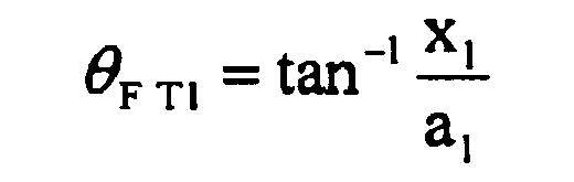

- Since the horizontal positional information an of the
healds 15 of each of the heald frames can be represented as an = a1 + (n - 1)×p using the pitch p of heald frames as described above, when the pitch p of heald frames and the positional information xn and yn of thehealds 15 of each of the heald frames are input, the shed angle in front of the frame (front upper shed angle θFTn, front lower shed angle θFBn) and the path length in front of the frame (front upper yarn length LFTn, front lower yarn length LFBn) for the n-th frame are calculated using the following set of equations.

- In the set of equations (2), an corresponds to "a horizontal distance from the cloth fell to the healds" according to the present invention. Here, xn and yn each correspond to "a vertical distance from the cloth-fell-side reference surface that is a horizontal surface passing through the cloth fell to the mail eyes of the healds when the shed of the warp yarns is fully open" according to the present invention.
- In
Fig. 5B , the shed angle of thewarp yarns 11 located between a heald frame, i.e., thehealds 15 and the non-cloth-fell-side restricting portion 14a of the upper yarn restricting pipe 14 (hereinafter, a position between the heald frame and the non-cloth-fell-side restricting portion will also be simply referred to as a position "at the rear of the frame") is, as described above, the angle between each of thewarp yarns 11 and a horizontal surface passing through the non-cloth-fell-side restricting portion 14a (non-cloth-fell-side reference surface) when the shed is fully open. - In the present embodiment, as described above, the upper
yarn restricting pipe 14 and theoval tube 13, which serve as restricting members, are disposed between the heald frames and thetension roller 12. Therefore, when the shed is upwardly open as illustrated inFig. 5B , a horizontal surface passing through the non-cloth-fell-side restricting portion 14a of the upperyarn restricting pipe 14 is the non-cloth-fell-side reference surface. When the shed is downwardly open (not shown), a horizontal surface passing through the non-cloth-fell-side restricting portion 13a of theoval tube 13 is the non-cloth-fell-side reference surface. - Now, it is assumed that the following items of positional information about the upper
yarn restricting pipe 14 are input to thesetting device 17 as known dimensions: - b: the horizontal distance from the cloth fell 16 to the non-cloth-fell-
side restricting portion 14a of the upperyarn restricting pipe 14, and - t: the vertical distance from the cloth-fell-side reference surface (warp line WL) to the non-cloth-fell-
side restricting portion 14a of the upperyarn restricting pipe 14. - In this case, regarding the first frame, the shed angle at the rear of the frame (rear upper shed angle) θRT1 when the shed is upwardly open (upper yarn) and the path length at the rear of the frame (rear upper yarn length) LRT1 when the shed is upwardly open (upper yarn) are calculated using the following set of equations.


- By using the horizontal positional information an of the
healds 15 of the n-th heald frame, the shed angle at the rear of the frame (rear upper shed angle θRTn, rear lower shed angle θRBn) and the path length at the rear of the frame (rear upper yarn length LRTn, rear lower yarn length LRBn) for the n-th frame are calculated using the following set of equations. Here, c and s are positional information about theoval tube 13, which restricts thewarp yarns 11 at the lower shedding position (not shown).

- In the set of equations (4), (b - an) and (c - an) correspond to "a horizontal distance from the healds to a non-cloth-fell-side restricting portion that restricts the warp path at a position that is on the non-cloth-fell side of the healds and that is nearest to the healds" according to the present invention. (xn - t) and (yn - s) correspond to "a vertical distance from a non-cloth-fell-side reference surface that is a horizontal surface passing through the non-cloth-fell-side restricting portion to mail eyes of the healds when a shed of the warp yarns is fully open". These distances may be directly input to the
setting device 17 as the positional information about the restricting members. - Referring to
Fig. 5C , it is assumed that the following positional information about thetension roller 12 is input to thesetting device 17 as a known dimension: - d: the horizontal distance from the cloth fell 16 to the
warp restricting portion 12a of thetension roller 12. - In this case, the path length LWT from the
warp restricting portion 12a of thetension roller 12 to the non-cloth-fell-side restricting portion 14a of the upperyarn restricting pipe 14 is calculated using the following equation.
- By using LWT of this equation, and LFT1 and LRT1, which have been calculated, the entire path length LaT1 for the first frame when the shed is upwardly open is calculated using the following equation.

- The entire path length LaTn for the n-th frame when the shed is upwardly open and the entire path length LaBn for the n-th frame when the shed is downwardly open are calculated using the following set of equations.

- In equations (5) and (7), (d - b) and (d - c) correspond to "a horizontal distance from the non-cloth-fell-side restricting portion to a warp restricting portion of the warp guide roller" according to the present invention. Here, t and s correspond to "a vertical distance from a let-off-side reference surface that is a horizontal surface passing through the warp restricting portion of the warp guide roller to the non-cloth-fell-side restricting portion (non-cloth-fell-side reference surface)" according to the present invention. These distances may be directly input to the
setting device 17 as the positional information about the restricting members. In the present embodiment, other restricting members, i.e., the upperyarn restricting pipe 14 for restricting the paths of upper yarns and theoval tube 13 for restricting the paths of lower yarns are disposed between thetension roller 12, which serves as a warp guide roller, and thehealds 15. If another restricting member for restricting the paths of upper yarns is not disposed between thetension roller 12 and thehealds 15, the path length LWT is zero. If another restricting member for restricting the paths of lower yarns is not disposed between thetension roller 12 and thehealds 15, the path length LWB is zero. - The shed angle and the path length, which have been calculated as described above, are output to the
display control unit 22 of thedisplay device 21 and displayed on thedisplay unit 23 in a predetermined display mode, for example, in a mode in which the numerical information and a diagram based on the numerical information are displayed as illustrated inFig. 4 . An operator can accurately grasp the conditions of the paths of thewarp yarns 11 by referring to numerical information about the shed angle and the path length displayed on thedisplay unit 23, which has been difficult to perform by visual observation. By looking at the diagram based on the numerical information, the operator can intuitively grasp the dispersion degree of the warp yarns. The diagram based on the numerical information may be drawn in such a way that the paths of thewarp yarns 11 are exaggerated in order to facilitate understanding of the dispersion degree of the warp yarns. - If the position of a restricting member is mechanically adjusted, the adjusted positional information about the disposition of the restricting member may be input again. For example, if the upper
yarn restricting pipe 14 is moved vertically upward, the vertical positional information t of the upperyarn restricting pipe 14, which has been input, may be updated by adding the amount of the vertical movement, and the calculatingdevice 20 may perform recalculation by using the updated positional information t. As a result of the recalculation, the shed angle and the path length that have been adjusted are displayed on the screen of thedisplay device 21 as the numerical information and the like. Therefore, initial determination as to whether or not the adjustment is appropriate can be performed without carrying out test weaving, and thereby an operation of adjusting the paths of thewarp yarns 11 can be performed easily in a short time. - In the embodiment described above, the present invention is applied to a loom in which the warp line WL is horizontal. However, the present invention is not limited thereto. As illustrated in
Fig. 7 , the present invention can be applied to a loom in which the warp line WL is inclined. As compared with the loom illustrated inFig. 2 , in the loom illustratedFig. 7 , the upperyarn restricting pipe 14, which serves as a restricting member, is omitted; and the position of awarp restricting portion 12b of thetension roller 12 is higher than that of the cloth fell 16 and therefore the warp line WL is inclined. Hereinafter, a second embodiment, in which the present invention is applied to the loom illustrated inFig. 7 , will be described in detail. - In the loom according to the present embodiment, the cloth-fell-side reference surface and the let-off-side reference surface do not coincide with the warp line WL, and the let-off-side reference surface is located at a position higher than that of the cloth-fell-side reference surface in the vertical direction. On the non-cloth-fell side of the heald frames, the
tension roller 12 is a restricting member that restricts thewarp yarns 11 that are moved to the upper shedding position when the shed of thewarp yarns 11 is opened at a position nearest to thehealds 15; and theoval tube 13 is a restricting member that restricts thewarp yarns 11 that are moved to the lower shedding position when the shed of thewarp yarns 11 is opened at a position nearest to the healds 15. Therefore, according to the present embodiment, non-cloth-fell-side restricting portions are the following two points: the final contact point (warp restrictingportion 12b) between thetension roller 12 and thewarp yarns 11 in the feed direction of thewarp yarns 11, and the final contact point between theoval tube 13 and thewarp yarns 11 in the feed direction of thewarp yarns 11. According to the present embodiment, there are two non-cloth-fell-side reference surfaces, i.e., a horizontal surface passing through thewarp restricting portion 12b (non-cloth-fell-side restricting portion) of thetension roller 12 and a horizontal surface passing through the non-cloth-fell-side restricting portion 13a of theoval tube 13. The non-cloth-fell-side reference surface passing through thewarp restricting portion 12b of thetension roller 12 is the same as a let-off-side reference surface. - As in the embodiment described above, to obtain the shed angle and the path length for each of the heald frames when the shed of warp yarns is fully open as warp path numerical information, if the horizontal positional information an of each heald frame is represented as an = a1 + (n - 1)×p using the pitch p of heald frames, for the n-th frame, the shed angles (front upper shed angle θFTn, front lower shed angle θFBn, rear upper shed angle θRTn, rear lower shed angle θRBn), and the path lengths (front upper yarn length LFTn, front lower yarn length LFBn, rear upper yarn length LRTn, rear lower yarn length LRBn, entire path length LaTn when the shed is upwardly open, and entire path length LaBn when the shed is downwardly open) are calculated using the following set of equations.

- When the offset amount of the
warp restricting portion 12b of thetension roller 12 with respect to the cloth fell 16 is denoted by u and it is assumed that an upward offset is represented by a positive value of u, the shed angles and the path lengths are calculated, for example, using the following set of equations, including the case where the upper yarn restricting pipe 14 (horizontal distance b, vertical distance t) is not omitted.
- If b = d and u = t, the set of equations (9) is the same as the set of equations (8), which is used to calculate the warp path numerical information in the case where the upper
yarn restricting pipe 14 is omitted as illustrated inFigs. 8A and 8B . - Heretofore, two embodiments of an information display apparatus according to the present invention have been described. However, the present invention is not limited to these embodiments and can be modified in various ways. Reference Position and the like for Positional Information about Restricting Members
- In the embodiments described above, the horizontal positional information about the restricting members is set with reference to the cloth fell. Alternatively, another specific reference position may be set and the distances from the reference position to the restricting members may be set. However, in this case, it is necessary that the distance from the reverence position to the cloth fell be set. Likewise, the reference surface of the vertical positional information about the restricting members may be a horizontal surface other than the cloth-fell-side reference surface, such as the let-off-side reference surface. As the positional information about the healds of each of the heald frames, for example, regarding the horizontal direction, the distance from the non-cloth-fell-side restricting portion to the centers of the mail eyes of the healds of the heald frame may be set; and regarding the vertical direction, the distance from the non-cloth-fell-side reference surface to the mail eyes of the healds of the heald frame when the shed of warp yarns is fully open may be set.
- In the embodiments described above, the angle between each of the warp yarns and a corresponding horizontal reference surface when the shed of the warp yarns is fully open, i.e., the angle between the warp yarn and the cloth-fell-side reference surface at a position in front of the frame and the angle between the warp yarn and the non-cloth-fell-side reference surface at a position at the rear of the frame are calculated as numerical values related to the dispersion degree of the warp yarns. Alternatively, the angle between each of the warp yarns and an imaginary vertical surface extending in the longitudinal direction (vertical direction) of the healds of the heald frames (hereinafter referred to as "imaginary vertical reference surface") may be calculated.
- For example, as illustrated in
Fig. 8A , imaginary vertical reference surfaces αn (heald frame No. n = 1, 2, ...) for respective heald frames may be set so as to pass through the centers of themail eyes 24. In this case, regarding thewarp yarn 11 for the n-th frame, the imaginary vertical reference surface for thewarp yarn 11 at a position in front of the frame is the same as that of thewarp yarn 11 at a position at the rear of the frame. - As illustrated in
Fig. 8B , an imaginary vertical reference surface for all heald frames may be set at each of a position in front of the frame and a position at the rear of the frame. In this case, an imaginary vertical reference surface βF for thewarp yarns 11 located in front of the frame is set between the cloth fell 16 and one of the heald frames that is nearest to the cloth fell 16 (the first frame), and an imaginary vertical reference surface βR for thewarp yarns 11 located at the rear of the frame is set between one of the heald frames that is farthest from the cloth fell 16 (the eighth frame in the embodiments described above) and the non-cloth-fell-side restricting portion 14a. Other Numerical Values related to Dispersion Degree of Warp Yarns - In the embodiments described above, the angle between each of the
warp yarns 11 and a predetermined reference surface is calculated as a numerical value related to the dispersion degree of warp yarns. Alternatively, the positions of the intersections of imaginary planes (for example, the imaginary vertical reference surfaces βF and βR inFig. 8B ) that are respectively set between the heald frames and the reference positions (cloth fell 16 and non-cloth-fell-side restricting portion 14a) and thewarp yarns 11 in the up-down direction, i.e., the distances HFTn, HRTn, and the like from a horizontal reference surface (cloth-fell-side reference surface) to the intersections may be calculated (Fig. 9A ). InFig. 9A , the cloth-fell-side reference surface coincides with the warp line WL. - In this case, the imaginary planes are set so as to extend in the up-down direction and extend parallel to the heald frames with respect to the width direction of the heald frames. At this time, regarding the warp sheet for the n-th frame, the heights of all of the positions at which the warp yarns included in the warp sheet intersect the imaginary planes are the same. Therefore, the imaginary planes need not be the planes extending vertically in the up-down direction as illustrated in
Fig. 9A as long as the imaginary planes extend parallel to the heald frames with respect to the width direction. Planes γF and γR illustrated inFig. 9B , which are inclined with respect to a horizontal surface in a side view of the warp shed, may be used as the imaginary planes. In the case ofFig. 9B , as in the case ofFig. 9A , the distances HFTn and HRTn from the horizontal reference surface may be calculated. Alternatively, as illustrated inFig. 9B , the distance HFTn, and HRTn, from a reference surface in a direction in which the imaginary planes extend in the up-down direction may be calculated. Relationship between Warp Path Numerical Information to be Obtained and Conditions of Shed and the like - Warp path numerical information to be obtained need not be that when the shed of warp yarns is fully open. Warp path numerical information for another specific main shaft rotation angle (including the case of a plurality of angles) may be obtained. In this case, it is necessary that positional information about the restricting members (members that influence the warp path) that are necessary for the specific main shaft rotation angle be set and stored in the
storage unit 19. In the embodiments described above, the shed angle and the path length of warp yarns when the shed is fully open are calculated as warp path numerical information. Instead of calculating both of these, the case of calculating only one of these is included in the scope of the present invention. - In the embodiments described above, both of the numerical information and the diagram based on the numerical information are displayed. Alternatively, only one of them may be displayed.
Claims (5)
- An information display apparatus (10) for a loom, the loom at least including, as a plurality of members that influence a warp path, a warp guide roller (12) and healds (15) attached to each of a plurality of heald frames, in which loom warp yarns (11) that are let off from a warp beam are redirected toward a cloth fell (16) by the warp guide roller (12), passed through the healds (15) of corresponding ones of the plurality of heald frames, and guided to the cloth fell (16), the information display apparatus (10) comprising:a setting device (17) in which positional information about a disposition of the plurality of members is set;a calculating device (20) that calculates numerical information about the warp path on the basis of the positional information; anda display device (21) that displays the numerical information calculated by the calculating device (20) and/or a diagram based on the numerical information on a screen.
- The information display apparatus (10) for a loom according to Claim 1,
wherein the calculating device (20) calculates for each heald frame on the basis of the positional information, as the numerical information, a numerical value related to a dispersion degree of the warp yarns (11) located on a cloth-fell side of the heald frame by using a horizontal distance from the cloth fell (16) to the healds (15) of the heald frame and a vertical distance from a cloth-fell-side reference surface that is a horizontal surface passing through the cloth fell (16) to mail eyes (24) of the healds (15) when a shed of the warp yarns (11) is fully open. - The information display apparatus (10) for a loom according to Claim 1 or 2,
wherein the calculating device (20) calculates for each heald frame on the basis of the positional information, as the numerical information, a numerical value related to a dispersion degree of the warp yarns (11) located on a non-cloth-fell side of the heald frame by using a horizontal distance from the healds (15) of the heald frame to a non-cloth-fell-side restricting portion (13a, 14a, 12b) that restricts the warp path at a position that is on the non-cloth-fell side of the healds (15) and that is nearest to the healds (15) and a vertical distance from a non-cloth-fell-side reference surface that is a horizontal surface passing through the non-cloth-fell-side restricting portion (13a, 14a, 12b) to mail eyes (24) of the healds (15) when a shed of the warp yarns (11) is fully open. - The information display apparatus (10) for a loom according to any one of Claims 1 to 3,
wherein the calculating device (20) calculates for each heald frame on the basis of the positional information, as the numerical information, a path length from the warp guide roller (12) to the cloth fell (16) when a shed of the warp yarns (11) is fully open by using the following distance information:a horizontal distance from the cloth fell (16) to the healds (15) of the heald frame,a vertical distance from the cloth-fell-side reference surface to mail eyes (24) of the healds (15) of the heald frame when the shed of the warp yarns (11) is fully open,a horizontal distance from the healds (15) of the heald frame to the non-cloth-fell-side restricting portion (13a, 14a, 12b),a vertical distance from the non-cloth-fell-side reference surface to the mail eyes (24) of the healds (15) of the heald frame when the shed of warp yarns (11) is fully open,a horizontal distance from the non-cloth-fell-side restricting portion (13a, 14a, 12b) to a warp restricting portion (12a, 12b) of the warp guide roller (12), anda vertical distance from a let-off-side reference surface that is a horizontal surface passing through the warp restricting portion (12a, 12b) of the warp guide roller (12) to the non-cloth-fell-side restricting portion (non-cloth-fell-side reference surface) (13a, 14a, 12b). - The information display apparatus (10) for a loom according to any one of Claims 1 to 4,
wherein the display device (21) displays the numerical information and/or the diagram based on the numerical information for at least two of the heald frames simultaneously on a single screen.
Applications Claiming Priority (1)
| Application Number | Priority Date | Filing Date | Title |
|---|---|---|---|
| JP2011224302A JP5860656B2 (en) | 2011-10-11 | 2011-10-11 | Information display device for loom |
Publications (2)
| Publication Number | Publication Date |
|---|---|
| EP2581477A1 true EP2581477A1 (en) | 2013-04-17 |
| EP2581477B1 EP2581477B1 (en) | 2014-10-22 |
Family
ID=47018004
Family Applications (1)
| Application Number | Title | Priority Date | Filing Date |
|---|---|---|---|
| EP20120005930 Not-in-force EP2581477B1 (en) | 2011-10-11 | 2012-08-17 | Information display apparatus for loom |
Country Status (3)
| Country | Link |
|---|---|
| EP (1) | EP2581477B1 (en) |
| JP (1) | JP5860656B2 (en) |
| CN (1) | CN103046212B (en) |
Cited By (1)
| Publication number | Priority date | Publication date | Assignee | Title |
|---|---|---|---|---|
| EP2902536A1 (en) * | 2014-02-03 | 2015-08-05 | Tsudakoma Kogyo Kabushiki Kaisha | Warp bending device for loom |
Families Citing this family (1)
| Publication number | Priority date | Publication date | Assignee | Title |
|---|---|---|---|---|
| CN115729292B (en) * | 2022-11-29 | 2023-12-08 | 金伦(苏州)织造有限公司 | Control system and method for water jet loom |
Citations (4)
| Publication number | Priority date | Publication date | Assignee | Title |
|---|---|---|---|---|
| EP0350980A1 (en) * | 1988-07-12 | 1990-01-17 | Picanol N.V. | Device for setting the warp tension on a weaving machine |
| JPH0610240A (en) | 1992-02-27 | 1994-01-18 | Picanol Nv | Device for fixing adjustably support arm or similar thing to machine frame, especially body of loom |
| EP0607747A1 (en) * | 1993-01-19 | 1994-07-27 | Sulzer RàTi Ag | Method for regulating the cloth line position and a weaving machine for realizing the method |
| WO1999014410A2 (en) * | 1997-09-13 | 1999-03-25 | Lindauer Dornier Gesellschaft Mbh | Method and device for regulating a back rest and/or a drop wire of a weaving machine |
Family Cites Families (6)
| Publication number | Priority date | Publication date | Assignee | Title |
|---|---|---|---|---|
| JP3147550B2 (en) * | 1992-10-29 | 2001-03-19 | 津田駒工業株式会社 | Cloth cutting position setting device |
| JP2004300643A (en) * | 2003-04-01 | 2004-10-28 | Toray Ind Inc | Weaving method of woven fabric |
| JP2004339626A (en) * | 2003-05-14 | 2004-12-02 | Tsudakoma Corp | Loom data input history display method |
| JP2006089885A (en) * | 2004-09-27 | 2006-04-06 | Tsudakoma Corp | Device for deciding set value |
| JP2007009355A (en) * | 2005-06-29 | 2007-01-18 | Tsudakoma Corp | Electric opening device of loom |
| JP5398176B2 (en) * | 2008-02-07 | 2014-01-29 | 津田駒工業株式会社 | Weft insertion status display method and display device for loom |
-
2011
- 2011-10-11 JP JP2011224302A patent/JP5860656B2/en not_active Expired - Fee Related
-
2012
- 2012-08-17 EP EP20120005930 patent/EP2581477B1/en not_active Not-in-force
- 2012-10-09 CN CN201210379788.2A patent/CN103046212B/en not_active Expired - Fee Related
Patent Citations (4)
| Publication number | Priority date | Publication date | Assignee | Title |
|---|---|---|---|---|
| EP0350980A1 (en) * | 1988-07-12 | 1990-01-17 | Picanol N.V. | Device for setting the warp tension on a weaving machine |
| JPH0610240A (en) | 1992-02-27 | 1994-01-18 | Picanol Nv | Device for fixing adjustably support arm or similar thing to machine frame, especially body of loom |
| EP0607747A1 (en) * | 1993-01-19 | 1994-07-27 | Sulzer RàTi Ag | Method for regulating the cloth line position and a weaving machine for realizing the method |
| WO1999014410A2 (en) * | 1997-09-13 | 1999-03-25 | Lindauer Dornier Gesellschaft Mbh | Method and device for regulating a back rest and/or a drop wire of a weaving machine |
Non-Patent Citations (1)
| Title |
|---|
| OSTHUS T ET AL: "AUTOMATISIERTE EINSTELLUNG VON STREICHBAUM UND KETTFADENWAECHTER IMPRAXISTEST", MELLIAND TEXTILBERICHTE, DEUTSCHER FACHVERLAG, FRANKFURT AM MAIN, DE, vol. 76, no. 10, 1 October 1995 (1995-10-01), XP000527867, ISSN: 0341-0781 * |
Cited By (1)
| Publication number | Priority date | Publication date | Assignee | Title |
|---|---|---|---|---|
| EP2902536A1 (en) * | 2014-02-03 | 2015-08-05 | Tsudakoma Kogyo Kabushiki Kaisha | Warp bending device for loom |
Also Published As
| Publication number | Publication date |
|---|---|
| JP5860656B2 (en) | 2016-02-16 |
| EP2581477B1 (en) | 2014-10-22 |
| CN103046212B (en) | 2016-03-16 |
| CN103046212A (en) | 2013-04-17 |
| JP2013083019A (en) | 2013-05-09 |
Similar Documents
| Publication | Publication Date | Title |
|---|---|---|
| US5027484A (en) | Tension controller for warping machine and warping method | |
| EP2581477B1 (en) | Information display apparatus for loom | |
| JP5550822B2 (en) | How to display the weft insertion status of the loom | |
| KR20140030305A (en) | Method and weaving machine having an apparatus for monitoring thread overtension | |
| JP3481258B2 (en) | Device for adjusting the backrest and / or drop wire of a loom | |
| EP1428917B1 (en) | A fluid jet loom suitable to perform a method of calculating timing of weft picking and a method of setting weft inserting condition | |
| KR101710491B1 (en) | method of weaving composite fabric including leno structure and woven structure by using single beam wounding tension balanced threads | |
| EP3987092B1 (en) | Weaving machine with device and method for detecting variations in pile-forming | |
| EP2772574B1 (en) | Information display method and information display device for loom | |
| JP7057117B2 (en) | How to set warp and weft flight information on an air injection loom | |
| CN101671909B (en) | Weft-insertion-condition display method for loom | |
| EP3987094B1 (en) | Shed-forming device | |
| EP3751035A1 (en) | Device for sensing warp thread tension in a weaving machine | |
| EP3205757A1 (en) | Weaving bar preventing method of loom and apparatus for the same | |
| EP3205756A1 (en) | Weaving bar preventing method of loom and apparatus for the same | |
| EP1600539A9 (en) | Display method and display device for loom | |
| JPS6342941A (en) | Control of warp yarn in loom | |
| JP2024131908A (en) | Pile fabric weight suitability judgement device | |
| Azzam et al. | Dynamic cloth fell movement. Part I: Critical review | |
| JPS6342943A (en) | Method for setting weaving condition in loom | |
| CZ2011490A3 (en) | Method of measuring weaving resistance on a weaving machine and apparatus for making the same | |
| TR2024011577A2 (en) | MOUTH OPENING SYSTEM WITH IMPACT PLATE | |
| JP2006070389A (en) | Warp tension monitoring method | |
| CZ22710U1 (en) | Device to measure weaving resistance on a weaving machine | |
| JPH08337944A (en) | Passive easing apparatus of loom |
Legal Events
| Date | Code | Title | Description |
|---|---|---|---|
| PUAI | Public reference made under article 153(3) epc to a published international application that has entered the european phase |
Free format text: ORIGINAL CODE: 0009012 |
|
| AK | Designated contracting states |
Kind code of ref document: A1 Designated state(s): AL AT BE BG CH CY CZ DE DK EE ES FI FR GB GR HR HU IE IS IT LI LT LU LV MC MK MT NL NO PL PT RO RS SE SI SK SM TR |
|
| AX | Request for extension of the european patent |
Extension state: BA ME |
|
| 17P | Request for examination filed |
Effective date: 20130919 |
|
| RBV | Designated contracting states (corrected) |
Designated state(s): AL AT BE BG CH CY CZ DE DK EE ES FI FR GB GR HR HU IE IS IT LI LT LU LV MC MK MT NL NO PL PT RO RS SE SI SK SM TR |
|
| RIC1 | Information provided on ipc code assigned before grant |
Ipc: D03J 1/00 20060101AFI20140401BHEP |
|
| GRAP | Despatch of communication of intention to grant a patent |
Free format text: ORIGINAL CODE: EPIDOSNIGR1 |
|
| INTG | Intention to grant announced |
Effective date: 20140523 |
|
| GRAS | Grant fee paid |
Free format text: ORIGINAL CODE: EPIDOSNIGR3 |
|
| GRAA | (expected) grant |
Free format text: ORIGINAL CODE: 0009210 |
|
| AK | Designated contracting states |
Kind code of ref document: B1 Designated state(s): AL AT BE BG CH CY CZ DE DK EE ES FI FR GB GR HR HU IE IS IT LI LT LU LV MC MK MT NL NO PL PT RO RS SE SI SK SM TR |
|
| REG | Reference to a national code |
Ref country code: GB Ref legal event code: FG4D |
|
| REG | Reference to a national code |
Ref country code: CH Ref legal event code: EP |
|
| REG | Reference to a national code |
Ref country code: AT Ref legal event code: REF Ref document number: 692723 Country of ref document: AT Kind code of ref document: T Effective date: 20141115 |
|
| REG | Reference to a national code |
Ref country code: IE Ref legal event code: FG4D |
|
| REG | Reference to a national code |
Ref country code: DE Ref legal event code: R096 Ref document number: 602012003441 Country of ref document: DE Effective date: 20141204 |
|
| REG | Reference to a national code |
Ref country code: NL Ref legal event code: VDEP Effective date: 20141022 |
|
| REG | Reference to a national code |
Ref country code: AT Ref legal event code: MK05 Ref document number: 692723 Country of ref document: AT Kind code of ref document: T Effective date: 20141022 |
|
| REG | Reference to a national code |
Ref country code: LT Ref legal event code: MG4D |
|
| PG25 | Lapsed in a contracting state [announced via postgrant information from national office to epo] |
Ref country code: ES Free format text: LAPSE BECAUSE OF FAILURE TO SUBMIT A TRANSLATION OF THE DESCRIPTION OR TO PAY THE FEE WITHIN THE PRESCRIBED TIME-LIMIT Effective date: 20141022 Ref country code: PT Free format text: LAPSE BECAUSE OF FAILURE TO SUBMIT A TRANSLATION OF THE DESCRIPTION OR TO PAY THE FEE WITHIN THE PRESCRIBED TIME-LIMIT Effective date: 20150223 Ref country code: IS Free format text: LAPSE BECAUSE OF FAILURE TO SUBMIT A TRANSLATION OF THE DESCRIPTION OR TO PAY THE FEE WITHIN THE PRESCRIBED TIME-LIMIT Effective date: 20150222 Ref country code: FI Free format text: LAPSE BECAUSE OF FAILURE TO SUBMIT A TRANSLATION OF THE DESCRIPTION OR TO PAY THE FEE WITHIN THE PRESCRIBED TIME-LIMIT Effective date: 20141022 Ref country code: NL Free format text: LAPSE BECAUSE OF FAILURE TO SUBMIT A TRANSLATION OF THE DESCRIPTION OR TO PAY THE FEE WITHIN THE PRESCRIBED TIME-LIMIT Effective date: 20141022 Ref country code: LT Free format text: LAPSE BECAUSE OF FAILURE TO SUBMIT A TRANSLATION OF THE DESCRIPTION OR TO PAY THE FEE WITHIN THE PRESCRIBED TIME-LIMIT Effective date: 20141022 Ref country code: NO Free format text: LAPSE BECAUSE OF FAILURE TO SUBMIT A TRANSLATION OF THE DESCRIPTION OR TO PAY THE FEE WITHIN THE PRESCRIBED TIME-LIMIT Effective date: 20150122 |
|
| PG25 | Lapsed in a contracting state [announced via postgrant information from national office to epo] |
Ref country code: RS Free format text: LAPSE BECAUSE OF FAILURE TO SUBMIT A TRANSLATION OF THE DESCRIPTION OR TO PAY THE FEE WITHIN THE PRESCRIBED TIME-LIMIT Effective date: 20141022 Ref country code: HR Free format text: LAPSE BECAUSE OF FAILURE TO SUBMIT A TRANSLATION OF THE DESCRIPTION OR TO PAY THE FEE WITHIN THE PRESCRIBED TIME-LIMIT Effective date: 20141022 Ref country code: AT Free format text: LAPSE BECAUSE OF FAILURE TO SUBMIT A TRANSLATION OF THE DESCRIPTION OR TO PAY THE FEE WITHIN THE PRESCRIBED TIME-LIMIT Effective date: 20141022 Ref country code: CY Free format text: LAPSE BECAUSE OF FAILURE TO SUBMIT A TRANSLATION OF THE DESCRIPTION OR TO PAY THE FEE WITHIN THE PRESCRIBED TIME-LIMIT Effective date: 20141022 Ref country code: SE Free format text: LAPSE BECAUSE OF FAILURE TO SUBMIT A TRANSLATION OF THE DESCRIPTION OR TO PAY THE FEE WITHIN THE PRESCRIBED TIME-LIMIT Effective date: 20141022 Ref country code: GR Free format text: LAPSE BECAUSE OF FAILURE TO SUBMIT A TRANSLATION OF THE DESCRIPTION OR TO PAY THE FEE WITHIN THE PRESCRIBED TIME-LIMIT Effective date: 20150123 Ref country code: LV Free format text: LAPSE BECAUSE OF FAILURE TO SUBMIT A TRANSLATION OF THE DESCRIPTION OR TO PAY THE FEE WITHIN THE PRESCRIBED TIME-LIMIT Effective date: 20141022 Ref country code: PL Free format text: LAPSE BECAUSE OF FAILURE TO SUBMIT A TRANSLATION OF THE DESCRIPTION OR TO PAY THE FEE WITHIN THE PRESCRIBED TIME-LIMIT Effective date: 20141022 |
|
| REG | Reference to a national code |
Ref country code: DE Ref legal event code: R097 Ref document number: 602012003441 Country of ref document: DE |
|
| PG25 | Lapsed in a contracting state [announced via postgrant information from national office to epo] |
Ref country code: RO Free format text: LAPSE BECAUSE OF FAILURE TO SUBMIT A TRANSLATION OF THE DESCRIPTION OR TO PAY THE FEE WITHIN THE PRESCRIBED TIME-LIMIT Effective date: 20141022 Ref country code: DK Free format text: LAPSE BECAUSE OF FAILURE TO SUBMIT A TRANSLATION OF THE DESCRIPTION OR TO PAY THE FEE WITHIN THE PRESCRIBED TIME-LIMIT Effective date: 20141022 Ref country code: CZ Free format text: LAPSE BECAUSE OF FAILURE TO SUBMIT A TRANSLATION OF THE DESCRIPTION OR TO PAY THE FEE WITHIN THE PRESCRIBED TIME-LIMIT Effective date: 20141022 Ref country code: SK Free format text: LAPSE BECAUSE OF FAILURE TO SUBMIT A TRANSLATION OF THE DESCRIPTION OR TO PAY THE FEE WITHIN THE PRESCRIBED TIME-LIMIT Effective date: 20141022 Ref country code: EE Free format text: LAPSE BECAUSE OF FAILURE TO SUBMIT A TRANSLATION OF THE DESCRIPTION OR TO PAY THE FEE WITHIN THE PRESCRIBED TIME-LIMIT Effective date: 20141022 |
|
| PLBE | No opposition filed within time limit |
Free format text: ORIGINAL CODE: 0009261 |
|
| STAA | Information on the status of an ep patent application or granted ep patent |
Free format text: STATUS: NO OPPOSITION FILED WITHIN TIME LIMIT |
|
| 26N | No opposition filed |
Effective date: 20150723 |
|
| PG25 | Lapsed in a contracting state [announced via postgrant information from national office to epo] |
Ref country code: SI Free format text: LAPSE BECAUSE OF FAILURE TO SUBMIT A TRANSLATION OF THE DESCRIPTION OR TO PAY THE FEE WITHIN THE PRESCRIBED TIME-LIMIT Effective date: 20141022 |
|
| PG25 | Lapsed in a contracting state [announced via postgrant information from national office to epo] |
Ref country code: LU Free format text: LAPSE BECAUSE OF FAILURE TO SUBMIT A TRANSLATION OF THE DESCRIPTION OR TO PAY THE FEE WITHIN THE PRESCRIBED TIME-LIMIT Effective date: 20150817 Ref country code: MC Free format text: LAPSE BECAUSE OF FAILURE TO SUBMIT A TRANSLATION OF THE DESCRIPTION OR TO PAY THE FEE WITHIN THE PRESCRIBED TIME-LIMIT Effective date: 20141022 |
|
| REG | Reference to a national code |
Ref country code: CH Ref legal event code: PL |
|
| PG25 | Lapsed in a contracting state [announced via postgrant information from national office to epo] |
Ref country code: CH Free format text: LAPSE BECAUSE OF NON-PAYMENT OF DUE FEES Effective date: 20150831 Ref country code: LI Free format text: LAPSE BECAUSE OF NON-PAYMENT OF DUE FEES Effective date: 20150831 |
|
| REG | Reference to a national code |
Ref country code: IE Ref legal event code: MM4A |
|
| REG | Reference to a national code |
Ref country code: FR Ref legal event code: ST Effective date: 20160429 |
|
| PG25 | Lapsed in a contracting state [announced via postgrant information from national office to epo] |
Ref country code: IE Free format text: LAPSE BECAUSE OF NON-PAYMENT OF DUE FEES Effective date: 20150817 |
|
| PG25 | Lapsed in a contracting state [announced via postgrant information from national office to epo] |
Ref country code: FR Free format text: LAPSE BECAUSE OF NON-PAYMENT OF DUE FEES Effective date: 20150831 |
|
| PG25 | Lapsed in a contracting state [announced via postgrant information from national office to epo] |
Ref country code: MT Free format text: LAPSE BECAUSE OF FAILURE TO SUBMIT A TRANSLATION OF THE DESCRIPTION OR TO PAY THE FEE WITHIN THE PRESCRIBED TIME-LIMIT Effective date: 20141022 |
|
| GBPC | Gb: european patent ceased through non-payment of renewal fee |
Effective date: 20160817 |
|
| PG25 | Lapsed in a contracting state [announced via postgrant information from national office to epo] |
Ref country code: HU Free format text: LAPSE BECAUSE OF FAILURE TO SUBMIT A TRANSLATION OF THE DESCRIPTION OR TO PAY THE FEE WITHIN THE PRESCRIBED TIME-LIMIT; INVALID AB INITIO Effective date: 20120817 Ref country code: BG Free format text: LAPSE BECAUSE OF FAILURE TO SUBMIT A TRANSLATION OF THE DESCRIPTION OR TO PAY THE FEE WITHIN THE PRESCRIBED TIME-LIMIT Effective date: 20141022 Ref country code: SM Free format text: LAPSE BECAUSE OF FAILURE TO SUBMIT A TRANSLATION OF THE DESCRIPTION OR TO PAY THE FEE WITHIN THE PRESCRIBED TIME-LIMIT Effective date: 20141022 |
|
| PG25 | Lapsed in a contracting state [announced via postgrant information from national office to epo] |
Ref country code: GB Free format text: LAPSE BECAUSE OF NON-PAYMENT OF DUE FEES Effective date: 20160817 |
|
| PG25 | Lapsed in a contracting state [announced via postgrant information from national office to epo] |
Ref country code: TR Free format text: LAPSE BECAUSE OF FAILURE TO SUBMIT A TRANSLATION OF THE DESCRIPTION OR TO PAY THE FEE WITHIN THE PRESCRIBED TIME-LIMIT Effective date: 20141022 |
|
| PG25 | Lapsed in a contracting state [announced via postgrant information from national office to epo] |
Ref country code: MK Free format text: LAPSE BECAUSE OF FAILURE TO SUBMIT A TRANSLATION OF THE DESCRIPTION OR TO PAY THE FEE WITHIN THE PRESCRIBED TIME-LIMIT Effective date: 20141022 |
|
| PG25 | Lapsed in a contracting state [announced via postgrant information from national office to epo] |
Ref country code: AL Free format text: LAPSE BECAUSE OF FAILURE TO SUBMIT A TRANSLATION OF THE DESCRIPTION OR TO PAY THE FEE WITHIN THE PRESCRIBED TIME-LIMIT Effective date: 20141022 |
|
| PGFP | Annual fee paid to national office [announced via postgrant information from national office to epo] |
Ref country code: IT Payment date: 20210712 Year of fee payment: 10 |
|
| PGFP | Annual fee paid to national office [announced via postgrant information from national office to epo] |
Ref country code: DE Payment date: 20210706 Year of fee payment: 10 Ref country code: BE Payment date: 20210716 Year of fee payment: 10 |
|
| REG | Reference to a national code |
Ref country code: DE Ref legal event code: R119 Ref document number: 602012003441 Country of ref document: DE |
|
| REG | Reference to a national code |
Ref country code: BE Ref legal event code: MM Effective date: 20220831 |
|
| PG25 | Lapsed in a contracting state [announced via postgrant information from national office to epo] |
Ref country code: IT Free format text: LAPSE BECAUSE OF NON-PAYMENT OF DUE FEES Effective date: 20220817 Ref country code: DE Free format text: LAPSE BECAUSE OF NON-PAYMENT OF DUE FEES Effective date: 20230301 |
|
| PG25 | Lapsed in a contracting state [announced via postgrant information from national office to epo] |
Ref country code: BE Free format text: LAPSE BECAUSE OF NON-PAYMENT OF DUE FEES Effective date: 20220831 |