EP2581308B1 - A distributed propulsion system and method of control - Google Patents
A distributed propulsion system and method of control Download PDFInfo
- Publication number
- EP2581308B1 EP2581308B1 EP12187088.5A EP12187088A EP2581308B1 EP 2581308 B1 EP2581308 B1 EP 2581308B1 EP 12187088 A EP12187088 A EP 12187088A EP 2581308 B1 EP2581308 B1 EP 2581308B1
- Authority
- EP
- European Patent Office
- Prior art keywords
- propulsion
- electrical
- propulsion units
- blades
- pitch
- Prior art date
- Legal status (The legal status is an assumption and is not a legal conclusion. Google has not performed a legal analysis and makes no representation as to the accuracy of the status listed.)
- Active
Links
Images


Classifications
-
- B—PERFORMING OPERATIONS; TRANSPORTING
- B64—AIRCRAFT; AVIATION; COSMONAUTICS
- B64D—EQUIPMENT FOR FITTING IN OR TO AIRCRAFT; FLIGHT SUITS; PARACHUTES; ARRANGEMENT OR MOUNTING OF POWER PLANTS OR PROPULSION TRANSMISSIONS IN AIRCRAFT
- B64D27/00—Arrangement or mounting of power plants in aircraft; Aircraft characterised by the type or position of power plants
- B64D27/02—Aircraft characterised by the type or position of power plants
- B64D27/30—Aircraft characterised by electric power plants
- B64D27/34—All-electric aircraft
-
- B—PERFORMING OPERATIONS; TRANSPORTING
- B64—AIRCRAFT; AVIATION; COSMONAUTICS
- B64D—EQUIPMENT FOR FITTING IN OR TO AIRCRAFT; FLIGHT SUITS; PARACHUTES; ARRANGEMENT OR MOUNTING OF POWER PLANTS OR PROPULSION TRANSMISSIONS IN AIRCRAFT
- B64D27/00—Arrangement or mounting of power plants in aircraft; Aircraft characterised by the type or position of power plants
- B64D27/02—Aircraft characterised by the type or position of power plants
- B64D27/30—Aircraft characterised by electric power plants
- B64D27/31—Aircraft characterised by electric power plants within, or attached to, wings
-
- B—PERFORMING OPERATIONS; TRANSPORTING
- B64—AIRCRAFT; AVIATION; COSMONAUTICS
- B64D—EQUIPMENT FOR FITTING IN OR TO AIRCRAFT; FLIGHT SUITS; PARACHUTES; ARRANGEMENT OR MOUNTING OF POWER PLANTS OR PROPULSION TRANSMISSIONS IN AIRCRAFT
- B64D31/00—Power plant control systems; Arrangement of power plant control systems in aircraft
- B64D31/16—Power plant control systems; Arrangement of power plant control systems in aircraft for electric power plants
-
- Y—GENERAL TAGGING OF NEW TECHNOLOGICAL DEVELOPMENTS; GENERAL TAGGING OF CROSS-SECTIONAL TECHNOLOGIES SPANNING OVER SEVERAL SECTIONS OF THE IPC; TECHNICAL SUBJECTS COVERED BY FORMER USPC CROSS-REFERENCE ART COLLECTIONS [XRACs] AND DIGESTS
- Y02—TECHNOLOGIES OR APPLICATIONS FOR MITIGATION OR ADAPTATION AGAINST CLIMATE CHANGE
- Y02T—CLIMATE CHANGE MITIGATION TECHNOLOGIES RELATED TO TRANSPORTATION
- Y02T50/00—Aeronautics or air transport
- Y02T50/60—Efficient propulsion technologies, e.g. for aircraft
Definitions
- This invention relates to an electrical distributed power system for an aircraft and a method of controlling the same.
- this invention relates to the use of blade pitch control to distribute power and manage parasitic oscillations within the system.
- One known arrangement for distributed propulsion is that used for helicopters where one or more engines is connected to two variable pitch rotors, either to two main rotors, or to a main rotor and a tail rotor, using a mechanical transmission system.
- Such systems typically incorporate shafts and fixed ratio gearboxes.
- Such systems do however include clutches to enable the engines individually to be disconnected from the rest of the system in the event that they are not producing power.
- One option for such an arrangement is to provide one or more electrical generators powered by gas turbine engines and use the generated electricity to power the various propulsion units which are arranged around the aircraft.
- Such a system is electrically complex and would require a high degree of control to keep it stable.
- Such control would conventionally come from power electronics. However these would be prohibitively large and heavy for the required levels of power and redundancy required for aero applications.
- the present invention seeks to provide an electrical distributed propulsive system which addresses the control of an electrical distributed propulsive system.
- the present invention provides a method of controlling power distribution in an electrical aircraft propulsive system and an electrical propulsion system for an aircraft as set out in the appended claims.
- the present invention provides a method of controlling power distribution in an electrical aircraft propulsive system, electrical aircraft propulsive system including: (i) a plurality of electrical propulsion units, each of the plurality of electrical propulsion units including a plurality of rotatable blades on a rotor, each blade having an adjustable pitch; (ii) a pitch adjusting mechanism for each of the plurality of electrical propulsion units, each pitch adjusting mechanism being configured to adjust the pitch of the plurality of rotatable blades of each of the plurality of plurality of blades of each of the plurality of propulsion units simultaneously so as to avoid a non-symmetrical load profile on a hub; (iii) at least one electrical machine electrically connected to the plurality of electrical propulsion units so as to provide electrical power when in use; and (iv) a control system; the method comprising the steps of: determining a required propulsion; determining whether the plurality of propulsion units is collectively delivering the required propulsion; and adjusting a pitch angle of
- adjustable pitch to control the power distribution in an electrical distributed propulsive system allows the power taken or delivered by a propulsion unit to be controlled without an electronic power convertor. This provides significant benefits in terms of weight and reliability for an aircraft based system.
- the method can also be used advantageously used to actively damp oscillations in the propulsive system.
- the step of determining whether the plurality of propulsion units is delivering the required propulsion may comprise, for each propulsion unit: monitoring a rotational state and pitch angle of the rotatable blades; and determining whether the rotational state is within a predetermined range.
- Monitoring the rotational state may include monitoring an angular position of the blades and determining either or both of the rotational speed and angular acceleration of the rotatable blades.
- the method may further comprise adjusting the pitch of the blades in one or more of the plurality of propulsion units such that the one or more propulsion units generate electrical energy for the electrical network.
- only a portion of the propulsion units in the plurality of propulsion units may be used to act as dampers.
- the present invention provides an electrical propulsion system for an aircraft, comprising: a plurality of electrical propulsion units each having a plurality of rotatable blades, each blade of the plurality of blades having an adjustable pitch; a pitch adjustment mechanism for each of the plurality of electrical propulsion units, each pitch adjustment mechanism being configured to adjust the pitch of the plurality of blades of each of the plurality of propulsion units simultaneously so as to avoid a non-symmetrical load profile on a hub; at least one electrical machine electrically connected to the plurality of propulsion units so as to provide electrical power in use; and a control system configured to: (i) determine a required propulsion and propulsion being delivered by the propulsion system, and (ii) adjust the pitch of the plurality of blades of at least one propulsion unit of the plurality of propulsion units as to increase or decrease the propulsion provided by that propulsion unit.
- the control system may be configured to: (i) monitor a rotational state and pitch angle of the rotatable blades, and (ii) determine whether the rotational state is within a predetermined range.
- Monitoring the rotational state may include: (i) monitoring an angular position of the blades, and (ii) determining either or both of the rotational speed and angular acceleration of the rotatable blades.
- the control system may be further configured to: (i) determine whether parasitic oscillations exist in the rotation of the blades in one or more of the plurality of propulsion units, and (ii) issue a control signal to the pitch adjustment mechanism of one or more of the plurality of propulsion units to adjust the pitch of the blades so as to damp the oscillations.
- the control system may further comprise: (i) a central control system configured to control a distribution of power between the plurality of propulsion units, and (ii) a secondary control unit at each of the plurality of propulsion units, the secondary control unit configured to determine whether the propulsion units are operating within predetermined rated limits.
- FIG. 1 there is shown a schematic representation of an aircraft having the electrical propulsive system 10 according to the present invention.
- the electrical propulsive system 10 includes a plurality of electrical propulsion units in the form of fans 12 which are rotatably driven by superconducting electrical machines.
- Each of the fan units 12 includes a rotor having fan blades 14 mounted on a rotatable hub and a blade pitch adjustment mechanism for synchronously adjusting the pitch of the blades 14 relative to the air flow which passes them in use.
- the propulsion units on the wings are shown as having blades 14, it will be appreciated that all of the propulsion units 12 include fans and blade arrangements as described.
- each fan blade 14 is mounted to the hub so as to be rotatable about its longitudinal axis via a shaft which passes into the hub and engages with the pitch control mechanism.
- the pitch control mechanism is typically a rotary electrical or hydraulic actuator which is arranged to drive the shafts via some gearing.
- the pitch control mechanism is operable on all of the fan blades simultaneously so as to avoid a non-symmetrical load profile on the hub. Altering the pitch changes the attitude of the blade to the oncoming airstream and the amount of torque experienced by the rotor. Hence, adjusting the attitude of the blades to a coarse setting increases the torque on the blade and reducing the pitch will reduce the torque.
- the electrical propulsion units 12 are placed in various locations around the fuselage 22 and wings 20 of the aircraft so as to ingest boundary layer air which is energised and exhausted to provide propulsive thrust. Having a plurality of smaller propulsion units 12 rather than two (or more) large gas turbine engines helps reduce drag and allows for a more efficient by pass ratio of the propulsive system 10, thereby increasing efficiency of the aircraft.
- propulsion units 12 located towards the trailing edge of the wing and two located towards a rear portion of the fuselage flanks. Two further units are located on the tips of the wings. All of the propulsion units 12 may be of the ducted variety or open rotor propellers as are known in the art.
- the electrical machines which drive the propulsion units 12 are superconducting synchronous machines having superconducting rotors which are permanently magnetised in use.
- the rotors are driven using stator windings which may or may not be superconducting.
- stator windings which may or may not be superconducting.
- Such machines are known in the art. As will be appreciated, the machines may be operated as motors or generators.
- the electrical propulsion system 10 also includes a plurality of electrical sources in the form of electrical generators 16 in the form of synchronous machines, which are driven by two main gas turbine engines 18 located underneath the wings 20.
- the gas turbine engines 18 operate in a conventional manner but are configured for operation as part of a distributed propulsion system 10 and as such may have a reduced bypass ratio so as to reduce aerodynamic drag.
- the electrical generators 16 and superconducting machines of the propulsion units 12 are electrically connected via cables in the form of a bus system 26 and as such collectively form an electrical network.
- the electrical network may also include ancillary equipment in the form of isolators and fault current limiters which are generally indicated by reference numeral 32.
- the electrical generators 16, bus system 26 and fault current limiters within the network may or may not be superconducting.
- the propulsive system 10 includes a control system which has at least one controller 28 which is configured, at least in part, to monitor and determine the required thrust for each propulsion unit and regulate the pitch of the fan blades to control the amount of propulsive force produced.
- the control system is also configured to monitor the stability of the system and control the pitch of the fan blades to damp out any parasitic oscillations which occur within the system. The control system and its operation are described in more detail below with reference to Figures 3 to 4 .
- the aircraft includes a cryogenic system to provide the cooling of the superconducting equipment.
- the cryogenic system includes one or more cryocoolers 30, which may be co-located with the controller or elsewhere, and which controls the flow of a refrigerant to the superconducting equipment.
- the refrigerant may be delivered to the superconducting equipment via a network of conduits which runs with the superconducting cables.
- the refrigerant conduits and superconducting cables are indicated by common dashed lines in Figure 1 .
- the superconducting materials may be any known in the art, but preferably a high temperature superconductor such as bismuth strontium calcium copper oxide (BSCCO) or yttrium barium copper oxide (YBCO) would be used and would be cooled by liquid nitrogen or hydrogen.
- BSCCO bismuth strontium calcium copper oxide
- YBCO yttrium barium copper oxide
- the use of the hydrogen is particularly beneficial as it could also be used to power the aircraft and would reduce the need for a cryocooling system on the aircraft as the liquid hydrogen could be stored as fuel in tanks before being used for cooling and subsequent burning in the engines.
- an auxiliary power unit 24 in the form of a small gas turbine which is arranged to provide electrical power to the aircraft when the main electrical generation system is inoperable, for example, prior to the engines 18 being started. This allows the cryogenic system to be powered prior to engine start.
- Oscillations may also be caused by a number of factors such as adjusting the power demand in the propulsive system and local disturbances in the air flow around a propulsion unit which affects the aerodynamic loading on the fan. Faults within the system, such as a loss of a propulsion unit due to an electrical fault or from a bird strike will also provide severe oscillatory disturbance.
- the control system of the present invention monitors the propulsive demand and the rotational state of the propulsion units to determine whether the power distribution is within acceptable limits and, where necessary, adjust the pitch of the fan blades, thereby forcing a response from a given propulsion unit. This allows the power dissipated by each propulsion unit to be adjusted as required and provides the option to actively dampen vibrations in the system without the need of convertor controlled electrical machines.
- FIG 2 provides an overview of the control system 210 and its integration with the electrical network described in Figure 1 .
- two engine control units 214a, 214b which correspond to the gas turbine engines 18 shown in Figure 1
- an interconnect and isolator control unit 215 which controls the physical configuration of the bus system
- individual propulsive control units 216a-h for each propulsion unit 12.
- Each engine 18 is configured to provide power to four separate propulsion units 12 which it does through a bus system 36. As shown in Figure 2 , there are two buses 236a, 236b for each engine 18 with each one being arranged to supply power to two of the propulsion units 12. As will be appreciated, the number of units matched to a particular engine and the distribution of power will depend on the power requirements of the system. Further, within a system there may be a master propulsion unit which determines the rotational frequency of the other propulsion units.
- the electrical distribution networks which include the buses may be selectively interconnected to allow for rerouting of power when required, for example, in the event of a fault.
- the distributed propulsion control unit 212 is a subset of a general aircraft control system 218 which controls all aspects of the aircraft such as the aerodynamic flight control surfaces and related systems.
- control systems are well known in the art and typically comprise some data processing equipment such as a processor and some memory.
- the distributed propulsion control unit 212 monitors and controls the gas turbine engines 18 and the distributed propulsion units 12. Thus, the distributed control unit 212 will receive data from the aircraft control system 218, such as the required demand, and determine the appropriate response required from the distributed propulsion units 12 and gas turbine engines 18.
- each propulsion unit includes its own control unit 216a-h which monitors the operating parameters of the propulsion units 12 and acts only in the event of a failure.
- the distributed propulsive control unit 212 may monitor for overspeeds in the rotor of the distributed propulsion unit 12 or a breakdown in the communications from the main propulsive control unit 212.
- the local control unit 216a-h will include a capacity to control the propulsion unit 12 in an independent safe mode, or to set the pitch of the blades to a feather position to minimise drag and the rotative force on the rotor.
- the interconnect and isolation control unit 215 monitors and controls a bus interconnector 220 such that it can reconfigure the electrical network in the event of a fault. For example, if a fault occurs in one of the propulsion units 12 and it needs to be isolated, the interconnect and isolation control unit 215 would receive a signal from the main distributed propulsion control unit 212 to isolate that unit. In some embodiments, the interconnect and isolator control unit 215 will be arranged to act autonomously.
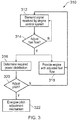
- Figure 3 shows a flow diagram 310 illustrating the control scheme implemented by the engine one control unit 214a shown in Figure 2 .
- the engine control unit 214a receives a signal of demand 312 which relates to the amount of thrust required, for example, from a throttle signal generated in the cockpit of the aircraft. On the basis of the required demand, the engine control unit determines the overall propulsive thrust and required fuel 314 and adjusts the fuel flow rate 316 to the engine accordingly.
- the engine control unit also evaluates the new distributed propulsive thrust 316 for each of the propulsion units 12 based on either the real time monitoring of the system, or on predicted values for a given rise in frequency. This evaluation may include adjustments to the net distributed power and adjustments to the distribution of the power amongst the various propulsion units 12 such that the aircraft can be made to yaw, for example.
- the associated amount of pitch adjustment is calculated 320 for each propulsion unit and a signal issued to energise the pitch adjustment mechanism 322, with the pitch angle being adjusted accordingly. Adjusting the pitch angle increases or decreases the thrust produced by the propulsion unit and allows the thrust delivered by the unit to be changed.
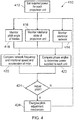
- Figure 4 shows a flow diagram 410 of an embodiment of how the control system determines whether to adjust the pitch of the blades for a required power distribution.
- the engine control unit 214a determines the amount of power or thrust 412 which is required from each propulsion unit 12 on the basis of one or more algorithms and the demand information.
- the engine control unit 214a then monitors the electrical network 414 to detect the frequency and phase of the current, the rotational state 416 of each propulsion unit 12, and the pitch angle of the blades 418.
- the rotational state relates to the acceleration or deceleration of the rotor which is achieved by examining the rotational position over time and integrating to find the speed and acceleration.
- other methods may exist for monitoring the rotational state. For example, by frequency analysis of currents or voltages in the associated electrical machines.
- the control system can determine the condition of the rotational state and calculate whether the rotor should be at steady state or accelerating. In the event that the rotor is accelerating (or decelerating) when it should not be, it is indicative that the system is oscillating, possibly in response to a change in demand. In this case, a prediction is made as to characteristic of the oscillation and the changes in pitch angle required to damp it. This evaluation may be based on an adaptive model which includes previous oscillatory behaviour.
- control system issues a control signal 426 to the pitch adjustment mechanism and continues to monitor the rotational state of the rotor so that a steady state or satisfactorily stable performance is achieved.
- the system is also configured to monitor the phase angles of the rotor and of the current of the electrical supply 422 to the propulsion unit in order to establish the load angle of the motor. In this way, the power being drawn by the motor can be calculated and the pitch angle can be adjusted should the power or torque exceed a rated value.
- the pitch angle of the blades could be adjusted such that reverse thrust is produced.
- electrical power could be generated and might be fed into the network to power other systems or be stored.
- the power could be dumped.
- Providing a negative pitch in this way may also be advantageous if the one of the motors loses synchronicity and needs to be resynchronised.
- Reverse thrust may be obtained by turning the blades either through fine pitch or through coarse pitch.
- the motors and generators within the system have different numbers of poles such they can rotate at different rotational speeds for the same alternating current frequency while the pole passing frequency remains synchronised. This is advantageous as it means the slower spool speed of the gas turbine engines can result in fast rotating propulsion units without the need of a gearbox or power electronics.
- the distributed propulsion units are optimised for a typical cruise condition and the proportion of the overall thrust provided by these systems can be reduced at climb and takeoff. This can help reduce the electrical demand on the system and reduce the size of the generators and propulsion units.
- the blade pitch of the distributed propulsion units can be reduced at lower altitudes to limit the power transferred to them and to keep within the design torque and current limits for the superconducting electrical machines.
- the control system includes the necessary sensors, control loops and algorithms for carrying out the various steps of the method as are generally known in the art.
- the pitch adjustment mechanism may include a position sensor in the form of an optical or Hall-Effect absolute rotary encoder which monitors the rotational position of each blade.
- vibration detection elements may also be various vibration detection elements in order to ascertain that all of the blades have moved synchronously.
- the rate of fuel flow to the engine may be made in accordance with predetermined values which relate the fuel burn to the electrical output of the generator and control of the fuel may incorporate various sensors, control loops and algorithms in order to provide the required electrical and mechanical power.
- the above described embodiments relate to electrical generators driven by gas turbine engines, it will be appreciated that the electrical power may be provided by one of the electrical propulsion units. Further, although the above embodiments relate to propulsion units which all have variable pitch blades, some of the propulsion units may have fixed blades.
Landscapes
- Engineering & Computer Science (AREA)
- Aviation & Aerospace Engineering (AREA)
- Supply And Distribution Of Alternating Current (AREA)
- Control Of Multiple Motors (AREA)
Description
- This invention relates to an electrical distributed power system for an aircraft and a method of controlling the same. In particular, this invention relates to the use of blade pitch control to distribute power and manage parasitic oscillations within the system.
- Conventional state of the art propulsion systems for large civil aircraft typically include one or more gas turbine engines placed under the wings of the aircraft. However, some studies have indicated that so-called distributed propulsion, which involves having numerous smaller propulsion units preferentially arranged around an aircraft, may provide some significant benefits in terms of noise reduction and fuel efficiency when compared with the current state of the art propulsive arrangements.
- One known arrangement for distributed propulsion is that used for helicopters where one or more engines is connected to two variable pitch rotors, either to two main rotors, or to a main rotor and a tail rotor, using a mechanical transmission system. Such systems typically incorporate shafts and fixed ratio gearboxes. Such systems do however include clutches to enable the engines individually to be disconnected from the rest of the system in the event that they are not producing power.
- It is also known to apply mechanically synchronised systems to vertical take-off aircraft such as tilt-rotor aircraft, where the rotor speeds are mechanically synchronised. In these transmission systems the power that is absorbed by each rotor, or that is generated through gyro-rotation, is regulated by means of a collective pitch mechanism, which sets the desired pitch angle on all of the blades of the rotor. Such a mechanical transmission system might also be applied to a more conventional aircraft with distributed propulsion, where the engines are wholly or partly separated from the rotors that provide the means of propulsion.
- It is also known to provide numerous electrical propulsion units which are located so as to capture and accelerate slow speed boundary layer air which has formed against the surface of the aircraft. This can lead to a significant reduction in overall fuel burn with the maximum benefit of boundary layer ingestion being achieved when the low speed flow is not mixed with the freestream flow, but is accelerated to homogeneous conditions by the propulsion system.
- One option for such an arrangement is to provide one or more electrical generators powered by gas turbine engines and use the generated electricity to power the various propulsion units which are arranged around the aircraft. However, such a system is electrically complex and would require a high degree of control to keep it stable. Such control would conventionally come from power electronics. However these would be prohibitively large and heavy for the required levels of power and redundancy required for aero applications.
- International patent application
WO 2005/100154 A1 discloses a method for determining a pitch angle of at least one blade of a helicopter main rotor. The method involves determining the pitch angle of the at least one blade according to a mathematical function independently of the pitch angle of each other blade of the rotor. Adjusting the pitch of an individual blade generates lateral or horizontal movement of the helicopter. - The present invention seeks to provide an electrical distributed propulsive system which addresses the control of an electrical distributed propulsive system.
- The present invention provides a method of controlling power distribution in an electrical aircraft propulsive system and an electrical propulsion system for an aircraft as set out in the appended claims.
- In a first aspect, the present invention provides a method of controlling power distribution in an electrical aircraft propulsive system, electrical aircraft propulsive system including: (i) a plurality of electrical propulsion units, each of the plurality of electrical propulsion units including a plurality of rotatable blades on a rotor, each blade having an adjustable pitch; (ii) a pitch adjusting mechanism for each of the plurality of electrical propulsion units, each pitch adjusting mechanism being configured to adjust the pitch of the plurality of rotatable blades of each of the plurality of plurality of blades of each of the plurality of propulsion units simultaneously so as to avoid a non-symmetrical load profile on a hub; (iii) at least one electrical machine electrically connected to the plurality of electrical propulsion units so as to provide electrical power when in use; and (iv) a control system; the method comprising the steps of: determining a required propulsion; determining whether the plurality of propulsion units is collectively delivering the required propulsion; and adjusting a pitch angle of the plurality of blades of at least one of the plurality of propulsion units so as to increase or decrease the propulsion provided by that propulsion unit.
- Using adjustable pitch to control the power distribution in an electrical distributed propulsive system allows the power taken or delivered by a propulsion unit to be controlled without an electronic power convertor. This provides significant benefits in terms of weight and reliability for an aircraft based system. The method can also be used advantageously used to actively damp oscillations in the propulsive system.
- The step of determining whether the plurality of propulsion units is delivering the required propulsion may comprise, for each propulsion unit: monitoring a rotational state and pitch angle of the rotatable blades; and determining whether the rotational state is within a predetermined range.
- Monitoring the rotational state may include monitoring an angular position of the blades and determining either or both of the rotational speed and angular acceleration of the rotatable blades.
- The method of the first aspect may further comprise the step of: determining whether there are parasitic oscillations in the rotation of the blades in one or more of the plurality of propulsion units and adjusting the pitch of the blades to damp the oscillations. Determining whether parasitic oscillations exist may include a step of monitoring an acceleration and deceleration of the rotor.
- The method may further comprise adjusting the pitch of the blades in one or more of the plurality of propulsion units such that the one or more propulsion units generate electrical energy for the electrical network.
- In one embodiment, only a portion of the propulsion units in the plurality of propulsion units may be used to act as dampers.
- In a second aspect the present invention provides an electrical propulsion system for an aircraft, comprising: a plurality of electrical propulsion units each having a plurality of rotatable blades, each blade of the plurality of blades having an adjustable pitch; a pitch adjustment mechanism for each of the plurality of electrical propulsion units, each pitch adjustment mechanism being configured to adjust the pitch of the plurality of blades of each of the plurality of propulsion units simultaneously so as to avoid a non-symmetrical load profile on a hub; at least one electrical machine electrically connected to the plurality of propulsion units so as to provide electrical power in use; and a control system configured to: (i) determine a required propulsion and propulsion being delivered by the propulsion system, and (ii) adjust the pitch of the plurality of blades of at least one propulsion unit of the plurality of propulsion units as to increase or decrease the propulsion provided by that propulsion unit.
- The control system may be configured to: (i) monitor a rotational state and pitch angle of the rotatable blades, and (ii) determine whether the rotational state is within a predetermined range.
- Monitoring the rotational state may include: (i) monitoring an angular position of the blades, and (ii) determining either or both of the rotational speed and angular acceleration of the rotatable blades.
- The control system may be further configured to: (i) determine whether parasitic oscillations exist in the rotation of the blades in one or more of the plurality of propulsion units, and (ii) issue a control signal to the pitch adjustment mechanism of one or more of the plurality of propulsion units to adjust the pitch of the blades so as to damp the oscillations.
- The control system may further comprise: (i) a central control system configured to control a distribution of power between the plurality of propulsion units, and (ii) a secondary control unit at each of the plurality of propulsion units, the secondary control unit configured to determine whether the propulsion units are operating within predetermined rated limits.
- The following drawings are used to describe embodiments of the invention, in which:
-
Figure 1 shows an overview of an aircraft having the electrical propulsive system according to a first embodiment. -
Figure 2 shows a schematic overview of the control system of an embodiment of the invention. -
Figure 3 shows a flow diagram highlighting certain aspects of a control method. -
Figure 4 shows a flow diagram highlighting certain aspects of a control method. - In
Figure 1 there is shown a schematic representation of an aircraft having the electricalpropulsive system 10 according to the present invention. The electricalpropulsive system 10 includes a plurality of electrical propulsion units in the form offans 12 which are rotatably driven by superconducting electrical machines. Each of thefan units 12 includes a rotor havingfan blades 14 mounted on a rotatable hub and a blade pitch adjustment mechanism for synchronously adjusting the pitch of theblades 14 relative to the air flow which passes them in use. Although only the propulsion units on the wings are shown as havingblades 14, it will be appreciated that all of thepropulsion units 12 include fans and blade arrangements as described. - The pitch adjustment mechanism can be any known in the art. In one embodiment, each
fan blade 14 is mounted to the hub so as to be rotatable about its longitudinal axis via a shaft which passes into the hub and engages with the pitch control mechanism. The pitch control mechanism is typically a rotary electrical or hydraulic actuator which is arranged to drive the shafts via some gearing. As mentioned, the pitch control mechanism is operable on all of the fan blades simultaneously so as to avoid a non-symmetrical load profile on the hub. Altering the pitch changes the attitude of the blade to the oncoming airstream and the amount of torque experienced by the rotor. Hence, adjusting the attitude of the blades to a coarse setting increases the torque on the blade and reducing the pitch will reduce the torque. As will be appreciated, it is also possible to set the pitch of the blades such that the electrical machine begins to extract energy from the airstream, thereby generating electrical power. - The
electrical propulsion units 12 are placed in various locations around thefuselage 22 andwings 20 of the aircraft so as to ingest boundary layer air which is energised and exhausted to provide propulsive thrust. Having a plurality ofsmaller propulsion units 12 rather than two (or more) large gas turbine engines helps reduce drag and allows for a more efficient by pass ratio of thepropulsive system 10, thereby increasing efficiency of the aircraft. - In the described embodiment, there are six
electrical propulsion units 12 located towards the trailing edge of the wing and two located towards a rear portion of the fuselage flanks. Two further units are located on the tips of the wings. All of thepropulsion units 12 may be of the ducted variety or open rotor propellers as are known in the art. - The electrical machines which drive the
propulsion units 12 are superconducting synchronous machines having superconducting rotors which are permanently magnetised in use. The rotors are driven using stator windings which may or may not be superconducting. Such machines are known in the art. As will be appreciated, the machines may be operated as motors or generators. - The
electrical propulsion system 10 also includes a plurality of electrical sources in the form ofelectrical generators 16 in the form of synchronous machines, which are driven by two maingas turbine engines 18 located underneath thewings 20. Thegas turbine engines 18 operate in a conventional manner but are configured for operation as part of a distributedpropulsion system 10 and as such may have a reduced bypass ratio so as to reduce aerodynamic drag. - The
electrical generators 16 and superconducting machines of thepropulsion units 12 are electrically connected via cables in the form of abus system 26 and as such collectively form an electrical network. As will be appreciated, the electrical network may also include ancillary equipment in the form of isolators and fault current limiters which are generally indicated byreference numeral 32. Theelectrical generators 16,bus system 26 and fault current limiters within the network may or may not be superconducting. - The
propulsive system 10 includes a control system which has at least onecontroller 28 which is configured, at least in part, to monitor and determine the required thrust for each propulsion unit and regulate the pitch of the fan blades to control the amount of propulsive force produced. The control system is also configured to monitor the stability of the system and control the pitch of the fan blades to damp out any parasitic oscillations which occur within the system. The control system and its operation are described in more detail below with reference toFigures 3 to 4 . - As is known in the art, superconductors are required to be held beneath critical levels of temperature, magnetic field and current density in order to be in a superconducting state. Hence, the aircraft includes a cryogenic system to provide the cooling of the superconducting equipment. The cryogenic system includes one or more cryocoolers 30, which may be co-located with the controller or elsewhere, and which controls the flow of a refrigerant to the superconducting equipment. The refrigerant may be delivered to the superconducting equipment via a network of conduits which runs with the superconducting cables. Hence, the refrigerant conduits and superconducting cables are indicated by common dashed lines in
Figure 1 . - The superconducting materials may be any known in the art, but preferably a high temperature superconductor such as bismuth strontium calcium copper oxide (BSCCO) or yttrium barium copper oxide (YBCO) would be used and would be cooled by liquid nitrogen or hydrogen. The use of the hydrogen is particularly beneficial as it could also be used to power the aircraft and would reduce the need for a cryocooling system on the aircraft as the liquid hydrogen could be stored as fuel in tanks before being used for cooling and subsequent burning in the engines.
- Towards the rear of the
fuselage 22 there is a located anauxiliary power unit 24, in the form of a small gas turbine which is arranged to provide electrical power to the aircraft when the main electrical generation system is inoperable, for example, prior to theengines 18 being started. This allows the cryogenic system to be powered prior to engine start. - In the arrangement described above, electrical power flows from the
generators 16 to the fans of thepropulsion units 12 which are rotated by the superconducting electrical machines so as to provide propulsion for the aircraft. Under steady state conditions, the amount of power entering the electrical network is the same as the power taken by the propulsion units such that there is a power balance within the system. If an increase in propulsive thrust is required, the fuel flow to the engines is increased so as to speed them up and increase the electrical frequency within the network. Due to the use of synchronous machines for the propulsion units, this leads to an increase in the rotational speed of all the fans. - Although the relationship between the propulsion units and engines is reasonably straightforward in steady state conditions, in reality the system would experience large amounts parasitic oscillations in the instantaneous rotor speeds of the propulsion units, particularly where the transmission system is entirely superconducting because it would have almost zero damping.
- Oscillations may also be caused by a number of factors such as adjusting the power demand in the propulsive system and local disturbances in the air flow around a propulsion unit which affects the aerodynamic loading on the fan. Faults within the system, such as a loss of a propulsion unit due to an electrical fault or from a bird strike will also provide severe oscillatory disturbance.
- Oscillations are problematic in terms of noise and vibration levels and may, in severe cases lead to general instability and the possible de-synchronisation of the electrical machines which would render the propulsion unit in question inoperable. Hence, these parasitic oscillations require damping.
- One option for controlling the electrical system in general and damping oscillations is to employ power electronics to control the propulsion units, thus effectively decoupling the units from the electrical network and regulating the power supply to each independently. However, this is problematic in aero applications due to the excessive weight of current power electronics. Further, aero systems require relatively high levels redundancy and backup to account for failures. This leads to increased components and weight which makes the choice of power electronics an undesirable one.
- The control system of the present invention monitors the propulsive demand and the rotational state of the propulsion units to determine whether the power distribution is within acceptable limits and, where necessary, adjust the pitch of the fan blades, thereby forcing a response from a given propulsion unit. This allows the power dissipated by each propulsion unit to be adjusted as required and provides the option to actively dampen vibrations in the system without the need of convertor controlled electrical machines.
-
Figure 2 provides an overview of thecontrol system 210 and its integration with the electrical network described inFigure 1 . In the described embodiment there is shown twoengine control units gas turbine engines 18 shown inFigure 1 , an interconnect andisolator control unit 215, which controls the physical configuration of the bus system, and individualpropulsive control units 216a-h for eachpropulsion unit 12. - Each
engine 18 is configured to provide power to fourseparate propulsion units 12 which it does through a bus system 36. As shown inFigure 2 , there are twobuses engine 18 with each one being arranged to supply power to two of thepropulsion units 12. As will be appreciated, the number of units matched to a particular engine and the distribution of power will depend on the power requirements of the system. Further, within a system there may be a master propulsion unit which determines the rotational frequency of the other propulsion units. - Although not shown, it will be appreciated that the electrical distribution networks which include the buses may be selectively interconnected to allow for rerouting of power when required, for example, in the event of a fault.
- The distributed
propulsion control unit 212 is a subset of a generalaircraft control system 218 which controls all aspects of the aircraft such as the aerodynamic flight control surfaces and related systems. Such control systems are well known in the art and typically comprise some data processing equipment such as a processor and some memory. - The distributed
propulsion control unit 212 monitors and controls thegas turbine engines 18 and the distributedpropulsion units 12. Thus, the distributedcontrol unit 212 will receive data from theaircraft control system 218, such as the required demand, and determine the appropriate response required from the distributedpropulsion units 12 andgas turbine engines 18. - In addition to the main distributed
propulsion control unit 212, each propulsion unit includes itsown control unit 216a-h which monitors the operating parameters of thepropulsion units 12 and acts only in the event of a failure. For example, the distributedpropulsive control unit 212 may monitor for overspeeds in the rotor of the distributedpropulsion unit 12 or a breakdown in the communications from the mainpropulsive control unit 212. Hence, in some embodiments, thelocal control unit 216a-h will include a capacity to control thepropulsion unit 12 in an independent safe mode, or to set the pitch of the blades to a feather position to minimise drag and the rotative force on the rotor. - The interconnect and
isolation control unit 215 monitors and controls abus interconnector 220 such that it can reconfigure the electrical network in the event of a fault. For example, if a fault occurs in one of thepropulsion units 12 and it needs to be isolated, the interconnect andisolation control unit 215 would receive a signal from the main distributedpropulsion control unit 212 to isolate that unit. In some embodiments, the interconnect andisolator control unit 215 will be arranged to act autonomously. -
Figure 3 shows a flow diagram 310 illustrating the control scheme implemented by the engine onecontrol unit 214a shown inFigure 2 . Theengine control unit 214a receives a signal ofdemand 312 which relates to the amount of thrust required, for example, from a throttle signal generated in the cockpit of the aircraft. On the basis of the required demand, the engine control unit determines the overall propulsive thrust and requiredfuel 314 and adjusts thefuel flow rate 316 to the engine accordingly. - Increasing or decreasing the fuel flow rate to engine one alters the spool speed of the engine and associated generator and electrical frequency within the network. Hence, the rotational speed of the synchronous speed of the rotors of the propulsion units will increase or decrease accordingly, which will affect the resultant thrust. Hence, when a change in demand is required, the engine control unit also evaluates the new distributed
propulsive thrust 316 for each of thepropulsion units 12 based on either the real time monitoring of the system, or on predicted values for a given rise in frequency. This evaluation may include adjustments to the net distributed power and adjustments to the distribution of the power amongst thevarious propulsion units 12 such that the aircraft can be made to yaw, for example. - When the required distribution of the power has been determined 318 the associated amount of pitch adjustment is calculated 320 for each propulsion unit and a signal issued to energise the
pitch adjustment mechanism 322, with the pitch angle being adjusted accordingly. Adjusting the pitch angle increases or decreases the thrust produced by the propulsion unit and allows the thrust delivered by the unit to be changed. -
Figure 4 shows a flow diagram 410 of an embodiment of how the control system determines whether to adjust the pitch of the blades for a required power distribution. Thus, theengine control unit 214a determines the amount of power or thrust 412 which is required from eachpropulsion unit 12 on the basis of one or more algorithms and the demand information. Theengine control unit 214a then monitors theelectrical network 414 to detect the frequency and phase of the current, therotational state 416 of eachpropulsion unit 12, and the pitch angle of theblades 418. In this embodiment, the rotational state relates to the acceleration or deceleration of the rotor which is achieved by examining the rotational position over time and integrating to find the speed and acceleration. However, the skilled person will appreciate that other methods may exist for monitoring the rotational state. For example, by frequency analysis of currents or voltages in the associated electrical machines. - Using the frequency in the electrical network and comparing this to the rotational speed of the
rotor 420, the control system can determine the condition of the rotational state and calculate whether the rotor should be at steady state or accelerating. In the event that the rotor is accelerating (or decelerating) when it should not be, it is indicative that the system is oscillating, possibly in response to a change in demand. In this case, a prediction is made as to characteristic of the oscillation and the changes in pitch angle required to damp it. This evaluation may be based on an adaptive model which includes previous oscillatory behaviour. - Once the necessary pitch angle has been established 424, the control system issues a
control signal 426 to the pitch adjustment mechanism and continues to monitor the rotational state of the rotor so that a steady state or satisfactorily stable performance is achieved. - The system is also configured to monitor the phase angles of the rotor and of the current of the
electrical supply 422 to the propulsion unit in order to establish the load angle of the motor. In this way, the power being drawn by the motor can be calculated and the pitch angle can be adjusted should the power or torque exceed a rated value. - In another embodiment, the pitch angle of the blades could be adjusted such that reverse thrust is produced. In this case electrical power could be generated and might be fed into the network to power other systems or be stored. Alternatively, the power could be dumped. Providing a negative pitch in this way may also be advantageous if the one of the motors loses synchronicity and needs to be resynchronised. Reverse thrust may be obtained by turning the blades either through fine pitch or through coarse pitch.
- In some embodiments, the motors and generators within the system have different numbers of poles such they can rotate at different rotational speeds for the same alternating current frequency while the pole passing frequency remains synchronised. This is advantageous as it means the slower spool speed of the gas turbine engines can result in fast rotating propulsion units without the need of a gearbox or power electronics.
- In some embodiments, the distributed propulsion units are optimised for a typical cruise condition and the proportion of the overall thrust provided by these systems can be reduced at climb and takeoff. This can help reduce the electrical demand on the system and reduce the size of the generators and propulsion units. In order to facilitate this, the blade pitch of the distributed propulsion units can be reduced at lower altitudes to limit the power transferred to them and to keep within the design torque and current limits for the superconducting electrical machines.
- It will be appreciated that the control system includes the necessary sensors, control loops and algorithms for carrying out the various steps of the method as are generally known in the art. For example, the pitch adjustment mechanism may include a position sensor in the form of an optical or Hall-Effect absolute rotary encoder which monitors the rotational position of each blade. There may also be various vibration detection elements in order to ascertain that all of the blades have moved synchronously. For example, the rate of fuel flow to the engine may be made in accordance with predetermined values which relate the fuel burn to the electrical output of the generator and control of the fuel may incorporate various sensors, control loops and algorithms in order to provide the required electrical and mechanical power.
- The above embodiments are examples of the invention defined by the scope of the claims below and should not be taken as limiting.
- Although the above described embodiments relate to electrical generators driven by gas turbine engines, it will be appreciated that the electrical power may be provided by one of the electrical propulsion units. Further, although the above embodiments relate to propulsion units which all have variable pitch blades, some of the propulsion units may have fixed blades.
Claims (12)
- A method of controlling power distribution in an electrical aircraft propulsive system, electrical aircraft propulsive system including:(i) a plurality of electrical propulsion units (12), each of the plurality of electrical propulsion units including a plurality of rotatable blades (14) on a rotor, each blade having an adjustable pitch;(ii) a pitch adjusting mechanism for each of the plurality of electrical propulsion units (12), each pitch adjusting mechanism being configured to adjust the pitch of the plurality of rotatable blades (14) of each of the plurality of plurality of blades of each of the plurality of propulsion units simultaneously so as to avoid a non-symmetrical load profile on a hub;(iii) at least one electrical machine electrically connected to the plurality of electrical propulsion units so as to provide electrical power when in use; and(iv) a control system (210);the method comprising the steps of:determining a required propulsion;determining whether the plurality of propulsion units is collectively delivering the required propulsion; andadjusting a pitch angle of the plurality of blades of at least one of the plurality of propulsion units so as to increase or decrease the propulsion provided by that propulsion unit.
- A method of controlling power distribution in an electrical aircraft propulsive system as claimed in claim 1 wherein the step of determining whether the plurality of propulsion units (12) is delivering the required propulsion comprises, for each propulsion unit:monitoring a rotational state and pitch angle of the rotatable blades; anddetermining whether the rotational state is within a predetermined range.
- A method of controlling power distribution in an electrical aircraft propulsive system as claimed in claim 2 wherein monitoring the rotational state includes monitoring an angular position of the blades and determining either or both of the rotational speed and angular acceleration of the rotatable blades (14).
- A method of controlling power distribution in an electrical aircraft propulsive system as claimed in any preceding claim further comprising the step of:determining whether there are parasitic oscillations in the rotation of the blades (14) in one or more of the plurality of propulsion units (12) and adjusting the pitch of the blades to damp the oscillations.
- A method of controlling power distribution in an electrical aircraft propulsive system as claimed in claim 4 wherein the determining whether parasitic oscillations exist includes a step of monitoring an acceleration and deceleration of the rotor.
- A method of controlling power distribution in an electrical aircraft propulsive system as claimed in any preceding claim further comprising adjusting the pitch of the blades (14) in one or more propulsion units (12) of the plurality of propulsion units such that the one or more propulsion units generate electrical energy for the electrical network.
- A method of controlling power distribution in an electrical aircraft propulsive system as claimed in any one of claims 4 to 6 wherein only a portion of the propulsion units (12) in the plurality of propulsion units is used to act as dampers.
- An electrical propulsion system for an aircraft, comprising:a plurality of electrical propulsion units (1) each having a plurality of rotatable blades (14), each blade of the plurality of blades having an adjustable pitch;a pitch adjustment mechanism for each of the plurality of electrical propulsion units (12), each pitch adjustment mechanism being configured to adjust the pitch of the plurality of blades (14) of each of the plurality of propulsion units simultaneously so as to avoid a non-symmetrical load profile on a hub;at least one electrical machine electrically connected to the plurality of propulsion units (12) so as to provide electrical power in use; anda control system configured to: (i) determine a required propulsion and propulsion being delivered by the propulsion system, and (ii) adjust the pitch of the plurality of blades of at least one propulsion unit of the plurality of propulsion units as to increase or decrease the propulsion provided by that propulsion unit.
- An electrical propulsion system for an aircraft as claimed in claim 8, wherein the control system is configured to: (i) monitor a rotational state and pitch angle of the rotatable blades, and (ii) determine whether the rotational state is within a predetermined range.
- An electrical propulsion system for an aircraft as claimed in claim 9, wherein the monitoring of the rotational state includes: (i) monitoring an angular position of the blades, and (ii) determining either or both of the rotational speed and angular acceleration of the rotatable blades.
- An electrical propulsion system for an aircraft as claimed in any one of claims 8 to 10, wherein control system is further configured to: (i) determine whether parasitic oscillations exist in the rotation of the blades in one or more of the plurality of propulsion units, and (ii) issue a control signal to the pitch adjustment mechanism of one or more of the plurality of propulsion units to adjust the pitch of the blades so as to damp the oscillations.
- An electrical propulsion system for an aircraft as claimed in any one of claims 8 to 10, wherein the control system comprises: (i) a central control system configured to control a distribution of power between the plurality of propulsion units, and (ii) a secondary control unit at each of the plurality of propulsion units, the secondary control unit configured to determine whether the propulsion units are operating within predetermined rated limits.
Applications Claiming Priority (1)
| Application Number | Priority Date | Filing Date | Title |
|---|---|---|---|
| GBGB1117692.2A GB201117692D0 (en) | 2011-10-13 | 2011-10-13 | A distributed propulsion system and method of control |
Publications (3)
| Publication Number | Publication Date |
|---|---|
| EP2581308A2 EP2581308A2 (en) | 2013-04-17 |
| EP2581308A3 EP2581308A3 (en) | 2018-01-17 |
| EP2581308B1 true EP2581308B1 (en) | 2019-01-23 |
Family
ID=45091992
Family Applications (1)
| Application Number | Title | Priority Date | Filing Date |
|---|---|---|---|
| EP12187088.5A Active EP2581308B1 (en) | 2011-10-13 | 2012-10-03 | A distributed propulsion system and method of control |
Country Status (3)
| Country | Link |
|---|---|
| US (1) | US9376213B2 (en) |
| EP (1) | EP2581308B1 (en) |
| GB (1) | GB201117692D0 (en) |
Families Citing this family (87)
| Publication number | Priority date | Publication date | Assignee | Title |
|---|---|---|---|---|
| FR3000321B1 (en) * | 2012-12-20 | 2016-07-22 | European Aeronautic Defence & Space Co Eads France | ELECTRICAL MACHINE WITH SUPERCONDUCTING COILS |
| FR3006997B1 (en) * | 2013-06-14 | 2016-12-23 | Airbus | AIRCRAFT WITH ELECTRICAL PROPULSION MEANS |
| US9475579B2 (en) | 2013-08-13 | 2016-10-25 | The United States Of America As Represented By The Administrator Of The National Aeronautics And Space Administration | Vertical take-off and landing vehicle with increased cruise efficiency |
| US10071801B2 (en) | 2013-08-13 | 2018-09-11 | The United States Of America As Represented By The Administrator Of Nasa | Tri-rotor aircraft capable of vertical takeoff and landing and transitioning to forward flight |
| GB201320988D0 (en) | 2013-11-28 | 2014-01-15 | Rolls Royce Plc | An aircraft |
| WO2015191017A1 (en) * | 2014-06-13 | 2015-12-17 | Oran Bülent | Propeller with super conductive electrical motor for air vehicles |
| EP3201086B1 (en) * | 2014-10-01 | 2019-07-31 | Sikorsky Aircraft Corporation | Power management between a propulsor and a coaxial rotor of a helicopter |
| CN111572356B (en) | 2014-11-12 | 2022-06-10 | 深圳市大疆创新科技有限公司 | Method and system for recovering motor power of movable object |
| DE102014224637B4 (en) * | 2014-12-02 | 2022-12-29 | Georgi Atanasov | Hybrid electric propulsion system for an aircraft |
| US10000293B2 (en) | 2015-01-23 | 2018-06-19 | General Electric Company | Gas-electric propulsion system for an aircraft |
| JP6437347B2 (en) | 2015-02-27 | 2018-12-12 | 三菱重工業株式会社 | Thrust generator and aircraft |
| US10370100B2 (en) | 2015-03-24 | 2019-08-06 | United States Of America As Represented By The Administrator Of Nasa | Aerodynamically actuated thrust vectoring devices |
| US10344613B2 (en) * | 2015-04-07 | 2019-07-09 | Sonic Blue Aerospace, Inc. | Hyperjet superconducting turbine blisk propulsion and power generation |
| GB201506473D0 (en) * | 2015-04-16 | 2015-06-03 | Rolls Royce Plc | Aircraft propulsion system |
| GB201508138D0 (en) | 2015-05-13 | 2015-06-24 | Rolls Royce Plc | Aircraft |
| DE102015209672A1 (en) * | 2015-05-27 | 2016-12-01 | Siemens Aktiengesellschaft | Airplane and method of operating a hydrofoil |
| US10676177B1 (en) * | 2015-05-29 | 2020-06-09 | Earthly Dynamics, LLC | Robotic landing gear for rotorcraft |
| CA2932101C (en) * | 2015-06-10 | 2023-10-03 | Rolls-Royce Corporation | Synchronizing motors for an electric propulsion system |
| CA2932102C (en) * | 2015-06-10 | 2024-04-30 | Rolls-Royce Corporation | Fault identification and isolation in an electric propulsion system |
| GB2539874A (en) | 2015-06-22 | 2017-01-04 | Rolls Royce Plc | Aircraft vapour trail control system |
| US9815560B2 (en) | 2015-09-21 | 2017-11-14 | General Electric Company | AFT engine nacelle shape for an aircraft |
| US10814991B2 (en) * | 2015-11-09 | 2020-10-27 | General Electric Company | Propulsion system and methods of use thereof |
| US9764848B1 (en) | 2016-03-07 | 2017-09-19 | General Electric Company | Propulsion system for an aircraft |
| US10227137B2 (en) | 2016-03-22 | 2019-03-12 | Ge Aviation Systems Llc | Hybrid power system for an aircraft |
| CA2954717C (en) | 2016-03-24 | 2025-01-07 | Rolls-Royce North American Technologies, Inc. | Windmill synchronization in an electric propulsion system |
| US10392120B2 (en) | 2016-04-19 | 2019-08-27 | General Electric Company | Propulsion engine for an aircraft |
| FR3050720B1 (en) * | 2016-04-28 | 2018-04-27 | Safran Aircraft Engines | AIRCRAFT HAS AT LEAST ONE AUXILIARY PROPULSIVE SYSTEM |
| GB2551552B (en) * | 2016-06-22 | 2018-10-03 | Rolls Royce Plc | An aircraft gas turbine engine comprising non-coaxial propulsors driven by an engine core comprising two axially spaced core modules |
| US10800539B2 (en) * | 2016-08-19 | 2020-10-13 | General Electric Company | Propulsion engine for an aircraft |
| US10676205B2 (en) | 2016-08-19 | 2020-06-09 | General Electric Company | Propulsion engine for an aircraft |
| US10308366B2 (en) | 2016-08-22 | 2019-06-04 | General Electric Company | Embedded electric machine |
| US10071811B2 (en) * | 2016-08-22 | 2018-09-11 | General Electric Company | Embedded electric machine |
| US10093428B2 (en) * | 2016-08-22 | 2018-10-09 | General Electric Company | Electric propulsion system |
| US10384774B2 (en) | 2016-09-08 | 2019-08-20 | General Electric Company | Tiltrotor propulsion system for an aircraft |
| US10730633B2 (en) * | 2016-11-22 | 2020-08-04 | Honeywell International Inc. | Hybrid electric aircraft propulsion system with motors using induction effect |
| US10647438B2 (en) * | 2016-12-07 | 2020-05-12 | Rolls-Royce North American Technologies, Inc. | Variable pitch for coordinated control |
| EP3566952B1 (en) | 2017-01-06 | 2021-01-27 | Northwestern Polytechnical University | Distributed propulsion system |
| US10822103B2 (en) | 2017-02-10 | 2020-11-03 | General Electric Company | Propulsor assembly for an aircraft |
| US10604268B2 (en) * | 2017-02-22 | 2020-03-31 | Pratt & Whitney Canada Corp. | Autothrottle control for turboprop engines |
| US10689082B2 (en) | 2017-04-12 | 2020-06-23 | Rolls-Royce North American Technologies, Inc. | Mechanically and electrically distributed propulsion |
| US10703496B2 (en) * | 2017-04-21 | 2020-07-07 | General Electric Company | Propulsion system for an aircraft |
| US10538337B2 (en) * | 2017-04-21 | 2020-01-21 | General Electric Company | Propulsion system for an aircraft |
| US10549845B2 (en) | 2017-05-26 | 2020-02-04 | United Technologies Corporation | Dedicated fans for boundary layer ingestion |
| US10723470B2 (en) | 2017-06-12 | 2020-07-28 | Raytheon Technologies Corporation | Aft fan counter-rotating turbine engine |
| US10762726B2 (en) | 2017-06-13 | 2020-09-01 | General Electric Company | Hybrid-electric propulsion system for an aircraft |
| JP6479893B2 (en) * | 2017-06-20 | 2019-03-06 | エスゼット ディージェイアイ テクノロジー カンパニー リミテッドSz Dji Technology Co.,Ltd | Power redistribution method and system for unmanned aerial vehicles |
| US20190061961A1 (en) * | 2017-08-22 | 2019-02-28 | General Electric Company | Aircraft propulsion system and method |
| GB201807771D0 (en) * | 2018-05-14 | 2018-06-27 | Rolls Royce Plc | Hybrid electric aircraft propulsion system |
| GB201807774D0 (en) | 2018-05-14 | 2018-06-27 | Rolls Royce Plc | Hybrid aircraft propulsion system |
| DE102018211459B4 (en) * | 2018-07-11 | 2021-10-21 | Rolls-Royce Deutschland Ltd & Co Kg | Aircraft propulsion system |
| FR3084646B1 (en) * | 2018-08-01 | 2021-10-22 | Safran | PROCESS FOR MANAGING THE PROPULSIVE POWER OF AN AIRCRAFT |
| US11332256B2 (en) | 2018-08-21 | 2022-05-17 | General Electric Company | Fault tolerant hybrid electric propulsion system for an aerial vehicle |
| US11156128B2 (en) | 2018-08-22 | 2021-10-26 | General Electric Company | Embedded electric machine |
| US11097849B2 (en) * | 2018-09-10 | 2021-08-24 | General Electric Company | Aircraft having an aft engine |
| US11167858B2 (en) * | 2018-09-10 | 2021-11-09 | Raytheon Technologies Corporation | Variable cycle compensation in a gas turbine engine |
| GB2587556B (en) * | 2018-10-15 | 2021-09-15 | Gkn Aerospace Services Ltd | Aircraft propulsion incorporating a cryogen |
| GB2578288B (en) * | 2018-10-15 | 2022-04-13 | Gkn Aerospace Services Ltd | Apparatus |
| GB2587560A (en) * | 2018-10-15 | 2021-03-31 | Gkn Aerospace Services Ltd | Apparatus |
| US11159024B2 (en) | 2018-11-08 | 2021-10-26 | Rolls-Royce North American Technologies, Inc. | Electrical architecture for hybrid propulsion |
| US11370554B2 (en) | 2018-11-08 | 2022-06-28 | Rolls-Royce North American Technologies, Inc. | Hybrid propulsion systems |
| US11225881B2 (en) * | 2018-11-08 | 2022-01-18 | Rolls-Royce North American Technologies, Inc. | Hybrid propulsion systems |
| FR3092948B1 (en) * | 2019-02-19 | 2021-02-26 | Safran | Electric system for synchronous propulsion channel |
| KR101970601B1 (en) * | 2019-03-13 | 2019-04-19 | 문창모 | Vertical takeoff and landing aircraft using hybrid-electric propulsion system |
| DE102019205152A1 (en) * | 2019-04-10 | 2020-10-15 | Rolls-Royce Deutschland Ltd & Co Kg | Electric propulsion system for an aircraft with minimal yaw moment |
| WO2020240567A1 (en) * | 2019-05-28 | 2020-12-03 | Eviation Aircraft Ltd. | Thrust control system and method |
| US11912422B2 (en) * | 2019-08-26 | 2024-02-27 | Hamilton Sundstrand Corporation | Hybrid electric aircraft and powerplant arrangements |
| GB2587669A (en) * | 2019-10-02 | 2021-04-07 | Advanced Mobility Res And Development Ltd | Systems and methods for aircraft |
| US11440673B2 (en) * | 2019-11-19 | 2022-09-13 | Ge Aviation Systems Llc | Aircraft propulsion system with voltage regulator |
| CA3101391A1 (en) * | 2019-12-03 | 2021-06-03 | United Technologies Advanced Projects, Inc. | Aircraft propulsion system and methods of feathering |
| US12187443B2 (en) | 2020-02-14 | 2025-01-07 | Bombardier Inc. | Excess thrust control for an aircraft |
| US12071219B2 (en) | 2020-03-03 | 2024-08-27 | Embraer S.A. | Propeller governor for electric synchronous thrust |
| US11753174B2 (en) | 2020-05-19 | 2023-09-12 | Pratt & Whitney Canada Corp. | Systems and methods for aircraft wing plug |
| US12227166B2 (en) | 2020-07-17 | 2025-02-18 | Rolls-Royce Corporation | Hybrid propulsion system power management |
| US12031479B2 (en) * | 2020-08-31 | 2024-07-09 | General Electric Company | Hybrid electric propulsion system load share |
| US20220363404A1 (en) * | 2021-05-14 | 2022-11-17 | Beta Air, Llc | Systems and methods for monitoring health of an electric vertical take-off and landing vehicle |
| US11873081B2 (en) | 2021-06-09 | 2024-01-16 | Textron Innovations Inc. | Supplemental engine power control |
| GB202109507D0 (en) * | 2021-07-01 | 2021-08-18 | Arrival Jet Ltd | Superduct |
| US12149154B2 (en) | 2021-07-22 | 2024-11-19 | General Electric Company | Electric machine having a hybrid insulative-conductive manifold |
| CN114137839B (en) * | 2021-11-26 | 2023-03-24 | 南京航空航天大学 | Cooperative control method suitable for multiple propellers of distributed electric propulsion aircraft |
| CN114044150B (en) * | 2021-11-29 | 2024-01-02 | 中国航发沈阳发动机研究所 | Optimization method and device for distributed hybrid electric propulsion system |
| US12071224B2 (en) | 2021-11-30 | 2024-08-27 | The Boeing Company | Aircraft boundary layer ingestion using multiple fans and associated methods |
| EP4463377A1 (en) * | 2022-01-14 | 2024-11-20 | Merien BV | Hybrid aircraft propulsion |
| US12077308B2 (en) | 2022-04-14 | 2024-09-03 | Textron Innovations Inc. | Supplemental engine transition control |
| US11691517B1 (en) | 2022-05-04 | 2023-07-04 | Beta Air, Llc | Emergency high voltage disconnection device for an electric aircraft |
| US12054245B2 (en) * | 2022-07-18 | 2024-08-06 | Textron Innovations Inc. | Optimizing usage of supplemental engine power |
| US12384556B2 (en) | 2023-01-25 | 2025-08-12 | Rolls-Royce Corporation | Hybrid propulsion systems with power sharing |
| US12371177B2 (en) | 2023-01-25 | 2025-07-29 | Rolls-Royce Corporation | Hybrid propulsion systems with power sharing |
Family Cites Families (18)
| Publication number | Priority date | Publication date | Assignee | Title |
|---|---|---|---|---|
| GB497156A (en) | 1937-06-15 | 1938-12-14 | Ivor Lusty | Controlling aircraft engines |
| US2462201A (en) * | 1943-02-02 | 1949-02-22 | Westinghouse Electric Corp | Electrical airplane propulsion |
| US3106369A (en) * | 1960-02-23 | 1963-10-08 | Curtiss Wright Corp | Aircraft and method of operating same |
| US3112088A (en) * | 1960-08-06 | 1963-11-26 | Westland Aircraft Ltd | Flying vehicles |
| US3426982A (en) * | 1967-02-03 | 1969-02-11 | Ronald L Markwood | Vertiplane vtol aircraft |
| US4720059A (en) * | 1986-12-31 | 1988-01-19 | Stearns Jr Hoyt A | High speed helicopter |
| US5000398A (en) * | 1988-10-25 | 1991-03-19 | Rashev Michael S | Flying multi-purpose aircraft carrier and method of V/STOL assisted flight |
| JP3916723B2 (en) * | 1997-05-15 | 2007-05-23 | 富士重工業株式会社 | Rotor blade of rotorcraft |
| US5973440A (en) * | 1997-07-07 | 1999-10-26 | Nitzsche; Fred | Structural component having means for actively varying its stiffness to control vibrations |
| US6065718A (en) * | 1998-03-23 | 2000-05-23 | Piasecki; Michael W. | Universal VTOL power and rotor system module |
| FR2798359B1 (en) * | 1999-09-14 | 2001-11-09 | Eurocopter France | IMPROVEMENTS ON TILTING ROTOR CONVERTIBLE AIRCRAFT |
| WO2005100154A1 (en) * | 2004-04-13 | 2005-10-27 | Wavefront Technology Pty Ltd | System for rotor head and rotor blade |
| CA2673642C (en) * | 2007-02-28 | 2012-11-13 | John M. Lawrence | Dual rotor vertical takeoff and landing rotorcraft |
| US8931732B2 (en) * | 2007-11-30 | 2015-01-13 | Sikorsky Aircraft Corporation | Electric powered rotary-wing aircraft |
| FR2933910B1 (en) * | 2008-07-18 | 2010-12-17 | Eurocopter France | HYBRID POWER PLANT AND METHOD FOR CONTROLLING SUCH A MOTOR INSTALLATION |
| US8052081B2 (en) * | 2008-08-22 | 2011-11-08 | Draganfly Innovations Inc. | Dual rotor helicopter with tilted rotational axes |
| US8616492B2 (en) * | 2009-10-09 | 2013-12-31 | Oliver Vtol, Llc | Three wing, six tilt-propulsion units, VTOL aircraft |
| FR2952907B1 (en) * | 2009-11-26 | 2011-12-09 | Eurocopter France | MOTOR INSTALLATION, HELICOPTER COMPRISING SUCH A MOTOR INSTALLATION, AND METHOD IMPLEMENTED BY THIS MOTOR INSTALLATION |
-
2011
- 2011-10-13 GB GBGB1117692.2A patent/GB201117692D0/en not_active Ceased
-
2012
- 2012-10-03 EP EP12187088.5A patent/EP2581308B1/en active Active
- 2012-10-04 US US13/644,900 patent/US9376213B2/en active Active
Non-Patent Citations (1)
| Title |
|---|
| None * |
Also Published As
| Publication number | Publication date |
|---|---|
| EP2581308A3 (en) | 2018-01-17 |
| GB201117692D0 (en) | 2011-11-23 |
| EP2581308A2 (en) | 2013-04-17 |
| US20130094963A1 (en) | 2013-04-18 |
| US9376213B2 (en) | 2016-06-28 |
Similar Documents
| Publication | Publication Date | Title |
|---|---|---|
| EP2581308B1 (en) | A distributed propulsion system and method of control | |
| US11174018B2 (en) | Anti-torque control using fixed blade pitch motors | |
| EP3613674B1 (en) | Fault tolerant hybrid electric propulsion system for an aerial vehicle | |
| US10647439B1 (en) | Variable frequency power system for hybrid electric aircraft propulsion | |
| US10131441B2 (en) | Aircraft electrical network | |
| US10526085B2 (en) | Electric distributed propulsion anti-torque redundant power and control system | |
| RU2724940C2 (en) | Vertical take-off and landing aircraft with hybrid power plant | |
| US9446842B2 (en) | Hybrid power rotary wing aircraft | |
| US10094293B2 (en) | In flight restart system and method for free turbine engine | |
| US20180354631A1 (en) | Hybrid-electric propulsion system for an aircraft | |
| EP3915880A1 (en) | Aircraft electrical power distribution | |
| US20210094694A1 (en) | Electric motor for a propeller engine | |
| US20150100181A1 (en) | Electrified Rotorcraft | |
| WO2024248918A1 (en) | Systems and methods for flight control of aircraft | |
| KR20200115312A (en) | A method of optimizing the noise generated in flight by a rotorcraft | |
| JP2022529612A (en) | Hybrid propulsion systems and methods for controlling such systems | |
| CN113264194A (en) | Extra thrust control for aircraft | |
| EP4166453B1 (en) | Aircraft electric propulsion system control method | |
| US20210394896A1 (en) | Electric distributed anti-torque architecture | |
| US12012215B2 (en) | Aircraft comprising at least two turboshaft engines and device configured to be connected to one of the turboshaft engines and method for controlling such an aircraft | |
| US20230184179A1 (en) | Aircraft propulsion system | |
| EP4155212B1 (en) | Aircraft hybrid propulsion system | |
| JP7511536B2 (en) | Aircraft Propulsion Systems | |
| US20260109450A1 (en) | Tail-rotor vibration dampener system | |
| CN119319916A (en) | Device and method for realizing vertical take-off and landing of aircraft based on control of rotation of universal joint |
Legal Events
| Date | Code | Title | Description |
|---|---|---|---|
| PUAI | Public reference made under article 153(3) epc to a published international application that has entered the european phase |
Free format text: ORIGINAL CODE: 0009012 |
|
| AK | Designated contracting states |
Kind code of ref document: A2 Designated state(s): AL AT BE BG CH CY CZ DE DK EE ES FI FR GB GR HR HU IE IS IT LI LT LU LV MC MK MT NL NO PL PT RO RS SE SI SK SM TR |
|
| AX | Request for extension of the european patent |
Extension state: BA ME |
|
| RAP1 | Party data changed (applicant data changed or rights of an application transferred) |
Owner name: ROLLS-ROYCE PLC |
|
| PUAL | Search report despatched |
Free format text: ORIGINAL CODE: 0009013 |
|
| AK | Designated contracting states |
Kind code of ref document: A3 Designated state(s): AL AT BE BG CH CY CZ DE DK EE ES FI FR GB GR HR HU IE IS IT LI LT LU LV MC MK MT NL NO PL PT RO RS SE SI SK SM TR |
|
| AX | Request for extension of the european patent |
Extension state: BA ME |
|
| RIC1 | Information provided on ipc code assigned before grant |
Ipc: B64D 27/24 20060101AFI20171213BHEP Ipc: B64D 27/02 20060101ALI20171213BHEP |
|
| STAA | Information on the status of an ep patent application or granted ep patent |
Free format text: STATUS: REQUEST FOR EXAMINATION WAS MADE |
|
| 17P | Request for examination filed |
Effective date: 20180712 |
|
| RBV | Designated contracting states (corrected) |
Designated state(s): AL AT BE BG CH CY CZ DE DK EE ES FI FR GB GR HR HU IE IS IT LI LT LU LV MC MK MT NL NO PL PT RO RS SE SI SK SM TR |
|
| GRAP | Despatch of communication of intention to grant a patent |
Free format text: ORIGINAL CODE: EPIDOSNIGR1 |
|
| STAA | Information on the status of an ep patent application or granted ep patent |
Free format text: STATUS: GRANT OF PATENT IS INTENDED |
|
| GRAS | Grant fee paid |
Free format text: ORIGINAL CODE: EPIDOSNIGR3 |
|
| GRAA | (expected) grant |
Free format text: ORIGINAL CODE: 0009210 |
|
| STAA | Information on the status of an ep patent application or granted ep patent |
Free format text: STATUS: THE PATENT HAS BEEN GRANTED |
|
| INTG | Intention to grant announced |
Effective date: 20181129 |
|
| AK | Designated contracting states |
Kind code of ref document: B1 Designated state(s): AL AT BE BG CH CY CZ DE DK EE ES FI FR GB GR HR HU IE IS IT LI LT LU LV MC MK MT NL NO PL PT RO RS SE SI SK SM TR |
|
| REG | Reference to a national code |
Ref country code: GB Ref legal event code: FG4D |
|
| REG | Reference to a national code |
Ref country code: CH Ref legal event code: EP |
|
| REG | Reference to a national code |
Ref country code: AT Ref legal event code: REF Ref document number: 1091256 Country of ref document: AT Kind code of ref document: T Effective date: 20190215 |
|
| REG | Reference to a national code |
Ref country code: IE Ref legal event code: FG4D |
|
| REG | Reference to a national code |
Ref country code: DE Ref legal event code: R096 Ref document number: 602012056160 Country of ref document: DE |
|
| REG | Reference to a national code |
Ref country code: NL Ref legal event code: MP Effective date: 20190123 |
|
| PG25 | Lapsed in a contracting state [announced via postgrant information from national office to epo] |
Ref country code: NL Free format text: LAPSE BECAUSE OF FAILURE TO SUBMIT A TRANSLATION OF THE DESCRIPTION OR TO PAY THE FEE WITHIN THE PRESCRIBED TIME-LIMIT Effective date: 20190123 |
|
| PG25 | Lapsed in a contracting state [announced via postgrant information from national office to epo] |
Ref country code: FI Free format text: LAPSE BECAUSE OF FAILURE TO SUBMIT A TRANSLATION OF THE DESCRIPTION OR TO PAY THE FEE WITHIN THE PRESCRIBED TIME-LIMIT Effective date: 20190123 Ref country code: SE Free format text: LAPSE BECAUSE OF FAILURE TO SUBMIT A TRANSLATION OF THE DESCRIPTION OR TO PAY THE FEE WITHIN THE PRESCRIBED TIME-LIMIT Effective date: 20190123 Ref country code: PL Free format text: LAPSE BECAUSE OF FAILURE TO SUBMIT A TRANSLATION OF THE DESCRIPTION OR TO PAY THE FEE WITHIN THE PRESCRIBED TIME-LIMIT Effective date: 20190123 Ref country code: LT Free format text: LAPSE BECAUSE OF FAILURE TO SUBMIT A TRANSLATION OF THE DESCRIPTION OR TO PAY THE FEE WITHIN THE PRESCRIBED TIME-LIMIT Effective date: 20190123 Ref country code: ES Free format text: LAPSE BECAUSE OF FAILURE TO SUBMIT A TRANSLATION OF THE DESCRIPTION OR TO PAY THE FEE WITHIN THE PRESCRIBED TIME-LIMIT Effective date: 20190123 Ref country code: NO Free format text: LAPSE BECAUSE OF FAILURE TO SUBMIT A TRANSLATION OF THE DESCRIPTION OR TO PAY THE FEE WITHIN THE PRESCRIBED TIME-LIMIT Effective date: 20190423 Ref country code: PT Free format text: LAPSE BECAUSE OF FAILURE TO SUBMIT A TRANSLATION OF THE DESCRIPTION OR TO PAY THE FEE WITHIN THE PRESCRIBED TIME-LIMIT Effective date: 20190523 |
|
| REG | Reference to a national code |
Ref country code: AT Ref legal event code: MK05 Ref document number: 1091256 Country of ref document: AT Kind code of ref document: T Effective date: 20190123 |
|
| PG25 | Lapsed in a contracting state [announced via postgrant information from national office to epo] |
Ref country code: HR Free format text: LAPSE BECAUSE OF FAILURE TO SUBMIT A TRANSLATION OF THE DESCRIPTION OR TO PAY THE FEE WITHIN THE PRESCRIBED TIME-LIMIT Effective date: 20190123 Ref country code: RS Free format text: LAPSE BECAUSE OF FAILURE TO SUBMIT A TRANSLATION OF THE DESCRIPTION OR TO PAY THE FEE WITHIN THE PRESCRIBED TIME-LIMIT Effective date: 20190123 Ref country code: GR Free format text: LAPSE BECAUSE OF FAILURE TO SUBMIT A TRANSLATION OF THE DESCRIPTION OR TO PAY THE FEE WITHIN THE PRESCRIBED TIME-LIMIT Effective date: 20190424 Ref country code: LV Free format text: LAPSE BECAUSE OF FAILURE TO SUBMIT A TRANSLATION OF THE DESCRIPTION OR TO PAY THE FEE WITHIN THE PRESCRIBED TIME-LIMIT Effective date: 20190123 Ref country code: IS Free format text: LAPSE BECAUSE OF FAILURE TO SUBMIT A TRANSLATION OF THE DESCRIPTION OR TO PAY THE FEE WITHIN THE PRESCRIBED TIME-LIMIT Effective date: 20190523 Ref country code: BG Free format text: LAPSE BECAUSE OF FAILURE TO SUBMIT A TRANSLATION OF THE DESCRIPTION OR TO PAY THE FEE WITHIN THE PRESCRIBED TIME-LIMIT Effective date: 20190423 |
|
| REG | Reference to a national code |
Ref country code: DE Ref legal event code: R097 Ref document number: 602012056160 Country of ref document: DE |
|
| PG25 | Lapsed in a contracting state [announced via postgrant information from national office to epo] |
Ref country code: EE Free format text: LAPSE BECAUSE OF FAILURE TO SUBMIT A TRANSLATION OF THE DESCRIPTION OR TO PAY THE FEE WITHIN THE PRESCRIBED TIME-LIMIT Effective date: 20190123 Ref country code: RO Free format text: LAPSE BECAUSE OF FAILURE TO SUBMIT A TRANSLATION OF THE DESCRIPTION OR TO PAY THE FEE WITHIN THE PRESCRIBED TIME-LIMIT Effective date: 20190123 Ref country code: CZ Free format text: LAPSE BECAUSE OF FAILURE TO SUBMIT A TRANSLATION OF THE DESCRIPTION OR TO PAY THE FEE WITHIN THE PRESCRIBED TIME-LIMIT Effective date: 20190123 Ref country code: AL Free format text: LAPSE BECAUSE OF FAILURE TO SUBMIT A TRANSLATION OF THE DESCRIPTION OR TO PAY THE FEE WITHIN THE PRESCRIBED TIME-LIMIT Effective date: 20190123 Ref country code: SK Free format text: LAPSE BECAUSE OF FAILURE TO SUBMIT A TRANSLATION OF THE DESCRIPTION OR TO PAY THE FEE WITHIN THE PRESCRIBED TIME-LIMIT Effective date: 20190123 Ref country code: IT Free format text: LAPSE BECAUSE OF FAILURE TO SUBMIT A TRANSLATION OF THE DESCRIPTION OR TO PAY THE FEE WITHIN THE PRESCRIBED TIME-LIMIT Effective date: 20190123 Ref country code: DK Free format text: LAPSE BECAUSE OF FAILURE TO SUBMIT A TRANSLATION OF THE DESCRIPTION OR TO PAY THE FEE WITHIN THE PRESCRIBED TIME-LIMIT Effective date: 20190123 |
|
| PG25 | Lapsed in a contracting state [announced via postgrant information from national office to epo] |
Ref country code: SM Free format text: LAPSE BECAUSE OF FAILURE TO SUBMIT A TRANSLATION OF THE DESCRIPTION OR TO PAY THE FEE WITHIN THE PRESCRIBED TIME-LIMIT Effective date: 20190123 |
|
| PLBE | No opposition filed within time limit |
Free format text: ORIGINAL CODE: 0009261 |
|
| STAA | Information on the status of an ep patent application or granted ep patent |
Free format text: STATUS: NO OPPOSITION FILED WITHIN TIME LIMIT |
|
| PG25 | Lapsed in a contracting state [announced via postgrant information from national office to epo] |
Ref country code: AT Free format text: LAPSE BECAUSE OF FAILURE TO SUBMIT A TRANSLATION OF THE DESCRIPTION OR TO PAY THE FEE WITHIN THE PRESCRIBED TIME-LIMIT Effective date: 20190123 |
|
| 26N | No opposition filed |
Effective date: 20191024 |
|
| PG25 | Lapsed in a contracting state [announced via postgrant information from national office to epo] |
Ref country code: SI Free format text: LAPSE BECAUSE OF FAILURE TO SUBMIT A TRANSLATION OF THE DESCRIPTION OR TO PAY THE FEE WITHIN THE PRESCRIBED TIME-LIMIT Effective date: 20190123 |
|
| PG25 | Lapsed in a contracting state [announced via postgrant information from national office to epo] |
Ref country code: TR Free format text: LAPSE BECAUSE OF FAILURE TO SUBMIT A TRANSLATION OF THE DESCRIPTION OR TO PAY THE FEE WITHIN THE PRESCRIBED TIME-LIMIT Effective date: 20190123 |
|
| PG25 | Lapsed in a contracting state [announced via postgrant information from national office to epo] |
Ref country code: MC Free format text: LAPSE BECAUSE OF FAILURE TO SUBMIT A TRANSLATION OF THE DESCRIPTION OR TO PAY THE FEE WITHIN THE PRESCRIBED TIME-LIMIT Effective date: 20190123 |
|
| REG | Reference to a national code |
Ref country code: CH Ref legal event code: PL |
|
| PG25 | Lapsed in a contracting state [announced via postgrant information from national office to epo] |
Ref country code: CH Free format text: LAPSE BECAUSE OF NON-PAYMENT OF DUE FEES Effective date: 20191031 Ref country code: LI Free format text: LAPSE BECAUSE OF NON-PAYMENT OF DUE FEES Effective date: 20191031 Ref country code: LU Free format text: LAPSE BECAUSE OF NON-PAYMENT OF DUE FEES Effective date: 20191003 |
|
| REG | Reference to a national code |
Ref country code: BE Ref legal event code: MM Effective date: 20191031 |
|
| PG25 | Lapsed in a contracting state [announced via postgrant information from national office to epo] |
Ref country code: BE Free format text: LAPSE BECAUSE OF NON-PAYMENT OF DUE FEES Effective date: 20191031 |
|
| PG25 | Lapsed in a contracting state [announced via postgrant information from national office to epo] |
Ref country code: IE Free format text: LAPSE BECAUSE OF NON-PAYMENT OF DUE FEES Effective date: 20191003 |
|
| PG25 | Lapsed in a contracting state [announced via postgrant information from national office to epo] |
Ref country code: CY Free format text: LAPSE BECAUSE OF FAILURE TO SUBMIT A TRANSLATION OF THE DESCRIPTION OR TO PAY THE FEE WITHIN THE PRESCRIBED TIME-LIMIT Effective date: 20190123 |
|
| PG25 | Lapsed in a contracting state [announced via postgrant information from national office to epo] |
Ref country code: MT Free format text: LAPSE BECAUSE OF FAILURE TO SUBMIT A TRANSLATION OF THE DESCRIPTION OR TO PAY THE FEE WITHIN THE PRESCRIBED TIME-LIMIT Effective date: 20190123 Ref country code: HU Free format text: LAPSE BECAUSE OF FAILURE TO SUBMIT A TRANSLATION OF THE DESCRIPTION OR TO PAY THE FEE WITHIN THE PRESCRIBED TIME-LIMIT; INVALID AB INITIO Effective date: 20121003 |
|
| PG25 | Lapsed in a contracting state [announced via postgrant information from national office to epo] |
Ref country code: MK Free format text: LAPSE BECAUSE OF FAILURE TO SUBMIT A TRANSLATION OF THE DESCRIPTION OR TO PAY THE FEE WITHIN THE PRESCRIBED TIME-LIMIT Effective date: 20190123 |
|
| P01 | Opt-out of the competence of the unified patent court (upc) registered |
Effective date: 20230528 |
|
| PGFP | Annual fee paid to national office [announced via postgrant information from national office to epo] |
Ref country code: DE Payment date: 20251028 Year of fee payment: 14 |
|
| PGFP | Annual fee paid to national office [announced via postgrant information from national office to epo] |
Ref country code: GB Payment date: 20251023 Year of fee payment: 14 |
|
| PGFP | Annual fee paid to national office [announced via postgrant information from national office to epo] |
Ref country code: FR Payment date: 20251027 Year of fee payment: 14 |