EP2581282A1 - Control device for hybrid vehicle - Google Patents
Control device for hybrid vehicle Download PDFInfo
- Publication number
- EP2581282A1 EP2581282A1 EP10853200.3A EP10853200A EP2581282A1 EP 2581282 A1 EP2581282 A1 EP 2581282A1 EP 10853200 A EP10853200 A EP 10853200A EP 2581282 A1 EP2581282 A1 EP 2581282A1
- Authority
- EP
- European Patent Office
- Prior art keywords
- engine
- vehicle
- lamp
- speed
- indicator lamp
- Prior art date
- Legal status (The legal status is an assumption and is not a legal conclusion. Google has not performed a legal analysis and makes no representation as to the accuracy of the status listed.)
- Withdrawn
Links
Images
Classifications
-
- B—PERFORMING OPERATIONS; TRANSPORTING
- B60—VEHICLES IN GENERAL
- B60W—CONJOINT CONTROL OF VEHICLE SUB-UNITS OF DIFFERENT TYPE OR DIFFERENT FUNCTION; CONTROL SYSTEMS SPECIALLY ADAPTED FOR HYBRID VEHICLES; ROAD VEHICLE DRIVE CONTROL SYSTEMS FOR PURPOSES NOT RELATED TO THE CONTROL OF A PARTICULAR SUB-UNIT
- B60W20/00—Control systems specially adapted for hybrid vehicles
- B60W20/10—Controlling the power contribution of each of the prime movers to meet required power demand
- B60W20/15—Control strategies specially adapted for achieving a particular effect
-
- B—PERFORMING OPERATIONS; TRANSPORTING
- B60—VEHICLES IN GENERAL
- B60K—ARRANGEMENT OR MOUNTING OF PROPULSION UNITS OR OF TRANSMISSIONS IN VEHICLES; ARRANGEMENT OR MOUNTING OF PLURAL DIVERSE PRIME-MOVERS IN VEHICLES; AUXILIARY DRIVES FOR VEHICLES; INSTRUMENTATION OR DASHBOARDS FOR VEHICLES; ARRANGEMENTS IN CONNECTION WITH COOLING, AIR INTAKE, GAS EXHAUST OR FUEL SUPPLY OF PROPULSION UNITS IN VEHICLES
- B60K6/00—Arrangement or mounting of plural diverse prime-movers for mutual or common propulsion, e.g. hybrid propulsion systems comprising electric motors and internal combustion engines
- B60K6/20—Arrangement or mounting of plural diverse prime-movers for mutual or common propulsion, e.g. hybrid propulsion systems comprising electric motors and internal combustion engines the prime-movers consisting of electric motors and internal combustion engines, e.g. HEVs
- B60K6/42—Arrangement or mounting of plural diverse prime-movers for mutual or common propulsion, e.g. hybrid propulsion systems comprising electric motors and internal combustion engines the prime-movers consisting of electric motors and internal combustion engines, e.g. HEVs characterised by the architecture of the hybrid electric vehicle
- B60K6/44—Series-parallel type
- B60K6/445—Differential gearing distribution type
-
- B—PERFORMING OPERATIONS; TRANSPORTING
- B60—VEHICLES IN GENERAL
- B60K—ARRANGEMENT OR MOUNTING OF PROPULSION UNITS OR OF TRANSMISSIONS IN VEHICLES; ARRANGEMENT OR MOUNTING OF PLURAL DIVERSE PRIME-MOVERS IN VEHICLES; AUXILIARY DRIVES FOR VEHICLES; INSTRUMENTATION OR DASHBOARDS FOR VEHICLES; ARRANGEMENTS IN CONNECTION WITH COOLING, AIR INTAKE, GAS EXHAUST OR FUEL SUPPLY OF PROPULSION UNITS IN VEHICLES
- B60K35/00—Instruments specially adapted for vehicles; Arrangement of instruments in or on vehicles
- B60K35/20—Output arrangements, i.e. from vehicle to user, associated with vehicle functions or specially adapted therefor
- B60K35/28—Output arrangements, i.e. from vehicle to user, associated with vehicle functions or specially adapted therefor characterised by the type of the output information, e.g. video entertainment or vehicle dynamics information; characterised by the purpose of the output information, e.g. for attracting the attention of the driver
-
- B—PERFORMING OPERATIONS; TRANSPORTING
- B60—VEHICLES IN GENERAL
- B60Q—ARRANGEMENT OF SIGNALLING OR LIGHTING DEVICES, THE MOUNTING OR SUPPORTING THEREOF OR CIRCUITS THEREFOR, FOR VEHICLES IN GENERAL
- B60Q9/00—Arrangement or adaptation of signal devices not provided for in one of main groups B60Q1/00 - B60Q7/00, e.g. haptic signalling
-
- B—PERFORMING OPERATIONS; TRANSPORTING
- B60—VEHICLES IN GENERAL
- B60W—CONJOINT CONTROL OF VEHICLE SUB-UNITS OF DIFFERENT TYPE OR DIFFERENT FUNCTION; CONTROL SYSTEMS SPECIALLY ADAPTED FOR HYBRID VEHICLES; ROAD VEHICLE DRIVE CONTROL SYSTEMS FOR PURPOSES NOT RELATED TO THE CONTROL OF A PARTICULAR SUB-UNIT
- B60W20/00—Control systems specially adapted for hybrid vehicles
-
- B—PERFORMING OPERATIONS; TRANSPORTING
- B60—VEHICLES IN GENERAL
- B60W—CONJOINT CONTROL OF VEHICLE SUB-UNITS OF DIFFERENT TYPE OR DIFFERENT FUNCTION; CONTROL SYSTEMS SPECIALLY ADAPTED FOR HYBRID VEHICLES; ROAD VEHICLE DRIVE CONTROL SYSTEMS FOR PURPOSES NOT RELATED TO THE CONTROL OF A PARTICULAR SUB-UNIT
- B60W50/00—Details of control systems for road vehicle drive control not related to the control of a particular sub-unit, e.g. process diagnostic or vehicle driver interfaces
- B60W50/08—Interaction between the driver and the control system
- B60W50/14—Means for informing the driver, warning the driver or prompting a driver intervention
-
- B—PERFORMING OPERATIONS; TRANSPORTING
- B60—VEHICLES IN GENERAL
- B60K—ARRANGEMENT OR MOUNTING OF PROPULSION UNITS OR OF TRANSMISSIONS IN VEHICLES; ARRANGEMENT OR MOUNTING OF PLURAL DIVERSE PRIME-MOVERS IN VEHICLES; AUXILIARY DRIVES FOR VEHICLES; INSTRUMENTATION OR DASHBOARDS FOR VEHICLES; ARRANGEMENTS IN CONNECTION WITH COOLING, AIR INTAKE, GAS EXHAUST OR FUEL SUPPLY OF PROPULSION UNITS IN VEHICLES
- B60K2360/00—Indexing scheme associated with groups B60K35/00 or B60K37/00 relating to details of instruments or dashboards
- B60K2360/16—Type of output information
- B60K2360/161—Explanation of functions, e.g. instructions
-
- B—PERFORMING OPERATIONS; TRANSPORTING
- B60—VEHICLES IN GENERAL
- B60W—CONJOINT CONTROL OF VEHICLE SUB-UNITS OF DIFFERENT TYPE OR DIFFERENT FUNCTION; CONTROL SYSTEMS SPECIALLY ADAPTED FOR HYBRID VEHICLES; ROAD VEHICLE DRIVE CONTROL SYSTEMS FOR PURPOSES NOT RELATED TO THE CONTROL OF A PARTICULAR SUB-UNIT
- B60W30/00—Purposes of road vehicle drive control systems not related to the control of a particular sub-unit, e.g. of systems using conjoint control of vehicle sub-units
- B60W30/18—Propelling the vehicle
- B60W30/20—Reducing vibrations in the driveline
- B60W2030/206—Reducing vibrations in the driveline related or induced by the engine
-
- B—PERFORMING OPERATIONS; TRANSPORTING
- B60—VEHICLES IN GENERAL
- B60W—CONJOINT CONTROL OF VEHICLE SUB-UNITS OF DIFFERENT TYPE OR DIFFERENT FUNCTION; CONTROL SYSTEMS SPECIALLY ADAPTED FOR HYBRID VEHICLES; ROAD VEHICLE DRIVE CONTROL SYSTEMS FOR PURPOSES NOT RELATED TO THE CONTROL OF A PARTICULAR SUB-UNIT
- B60W2510/00—Input parameters relating to a particular sub-units
- B60W2510/06—Combustion engines, Gas turbines
- B60W2510/0638—Engine speed
-
- B—PERFORMING OPERATIONS; TRANSPORTING
- B60—VEHICLES IN GENERAL
- B60W—CONJOINT CONTROL OF VEHICLE SUB-UNITS OF DIFFERENT TYPE OR DIFFERENT FUNCTION; CONTROL SYSTEMS SPECIALLY ADAPTED FOR HYBRID VEHICLES; ROAD VEHICLE DRIVE CONTROL SYSTEMS FOR PURPOSES NOT RELATED TO THE CONTROL OF A PARTICULAR SUB-UNIT
- B60W2520/00—Input parameters relating to overall vehicle dynamics
- B60W2520/10—Longitudinal speed
-
- Y—GENERAL TAGGING OF NEW TECHNOLOGICAL DEVELOPMENTS; GENERAL TAGGING OF CROSS-SECTIONAL TECHNOLOGIES SPANNING OVER SEVERAL SECTIONS OF THE IPC; TECHNICAL SUBJECTS COVERED BY FORMER USPC CROSS-REFERENCE ART COLLECTIONS [XRACs] AND DIGESTS
- Y02—TECHNOLOGIES OR APPLICATIONS FOR MITIGATION OR ADAPTATION AGAINST CLIMATE CHANGE
- Y02T—CLIMATE CHANGE MITIGATION TECHNOLOGIES RELATED TO TRANSPORTATION
- Y02T10/00—Road transport of goods or passengers
- Y02T10/10—Internal combustion engine [ICE] based vehicles
- Y02T10/40—Engine management systems
-
- Y—GENERAL TAGGING OF NEW TECHNOLOGICAL DEVELOPMENTS; GENERAL TAGGING OF CROSS-SECTIONAL TECHNOLOGIES SPANNING OVER SEVERAL SECTIONS OF THE IPC; TECHNICAL SUBJECTS COVERED BY FORMER USPC CROSS-REFERENCE ART COLLECTIONS [XRACs] AND DIGESTS
- Y02—TECHNOLOGIES OR APPLICATIONS FOR MITIGATION OR ADAPTATION AGAINST CLIMATE CHANGE
- Y02T—CLIMATE CHANGE MITIGATION TECHNOLOGIES RELATED TO TRANSPORTATION
- Y02T10/00—Road transport of goods or passengers
- Y02T10/60—Other road transportation technologies with climate change mitigation effect
- Y02T10/62—Hybrid vehicles
-
- Y—GENERAL TAGGING OF NEW TECHNOLOGICAL DEVELOPMENTS; GENERAL TAGGING OF CROSS-SECTIONAL TECHNOLOGIES SPANNING OVER SEVERAL SECTIONS OF THE IPC; TECHNICAL SUBJECTS COVERED BY FORMER USPC CROSS-REFERENCE ART COLLECTIONS [XRACs] AND DIGESTS
- Y10—TECHNICAL SUBJECTS COVERED BY FORMER USPC
- Y10S—TECHNICAL SUBJECTS COVERED BY FORMER USPC CROSS-REFERENCE ART COLLECTIONS [XRACs] AND DIGESTS
- Y10S903/00—Hybrid electric vehicles, HEVS
- Y10S903/902—Prime movers comprising electrical and internal combustion motors
- Y10S903/903—Prime movers comprising electrical and internal combustion motors having energy storing means, e.g. battery, capacitor
Definitions
- the present invention relates to a control device of a hybrid vehicle having an indicator lamp for informing the driver that the vehicle is motor running.
- a hybrid vehicle is well known that has an engine and a motor as driving force sources for running and that, by turning on an indicator lamp, informs the driver that the vehicle is in motor running mode where the vesicle runs using only the motor as the driving force source for running.
- Vehicles described in Patent Documents 1 to 5 are examples thereof. Specifically, Patent Document 1 describes turning on and off a motor regeneration lamp or a motor power running lamp based on a detection result of the motor operating state.
- Patient Document 3 describes turning on an electric-only indicator when the vehicle is operating in an electric-only mode where the vehicle runs using only the motor.
- the indicator lamp In motor running mode, the indicator lamp is desired to be on as early as possible and as long as possible. It is thus conceivable to turn on the indicator lamp not only during the motor running mode where the engine stops rotating but also from when executing a process (engine rotation stop process) for stopping the engine from rotating. That is, it is conceivable to turn on the indicator lamp when e.g. the engine does not work (operate) as a driving force source for running irrespective of whether the engine stops rotating.
- Patent Document 1 Japanese Laid-Open Patent Publication No. 9-98501
- the engine vibration frequency band is called an engine resonance band and the engine resonance band may exist in a lower rotation range than the idling speed of the engine. In such a case, a certain time is required for the engine speed to be lowered to the engine resonance band after the start of the engine rotation stop process.
- the illumination of the indicator lamp from the start of the engine rotation stop process does not coincide with the driver's recognition of the engine stop based on the vehicle vibration occurring when passing through the engine resonance band in the engine rotation stop process, in other words, there is a time gap (interval) between the indicator lamp illumination and the engine stop recognition, so that the driver may easily have an uncomfortable feeling.
- the driver is easy to feel a vehicle vibration (vibration at engine stop) in the engine rotation stop process and may more easily have the uncomfortable feeling.
- the engine rotation stop process may be interrupted to lower the raised engine speed by the electric motor, after which engine rotation stop process may be resumed. This may allow the indicator lamp turned on from the start of the engine rotation stop process to temporarily go off and then again go on, i.e., this may bring about a blinking of the indicator lamp where the indicator lamp frequently goes can and of, with the result that the driver may have an uncomfortable feeling of the lamp blinking.
- the present invention was conceived in view of the above circumstances as a background and an object thereof is to provide a control device of a hybrid vehicle capable of suppressing an uncomfortable feeling induced by, from the start of an engine rotation stop process, turning on an indicator lamp for informing the driver that the vehicle is motor running.
- the present invention provides a control device of a hybrid vehicle (a) having an engine and a motor as driving force sources for running and configured to inform, a driver that the vehicle is in motor running mode where the vehicle runs using only the motor as the driving force source for running, by turning on an indicator lamp, from the start of an engine rotation stop process preceding the motor running mode, therein (b) in a predetermined low vehicle speed range previously defined as a vehicle speed range where the driver is sensitive to a vehicle vibration due to passage of an engine speed through an engine resonance band, turning on of the indicator lamp is delayed from the start of the engine rotation stop process.
- the turning on of the indicator lamp is delayed from the start of the engine rotation stop process when the vehicle speed is in a predetermined low vehicle speed range that is previously defined as a vehicle speed range where the driver is easy to feet the vehicle vibration attendant on passage of the engine speed through the engine resonance band, whereupon in the case where the vehicle is in the predetermined low vehicle speed range for example, a time difference can be suppressed between the illumination timing of the indicator lamp in the engine rotation stop process and the stop timing of the engine that the driver feels by the vehicle vibration occurring when the engine speed lowered in the engine rotation stop process passes through the engine resonance band.
- the indicator lamp In the case where the vehicle is not in the predetermined low vehicle speed range, i.e., where the vehicle is in a vehicle speed range originally hard to feel the vehicle vibration, the indicator lamp is allowed to go on as soon as possible after the start of the engine rotation stop process. Thus, the indicator lamp can be turned on as early as possible and the uncomfortable feeling arising from the illumination of the indicator lamp is suppressed.
- turning on of the indicator lamp is delayed from the start of the engine rotation stop process, based on the engine speed lowered for engine rotation stop. Consequently, in the case where the vehicle is in the predetermined low vehicle speed range for example, a time difference can be property suppressed between the illumination timing of the indicator lamp in the engine rotation stop process and the stop timing of the engine that the driver feels by the vehicle vibration occurring when the engine speed lowered in the engine rotation stop process passes through the engine resonance band.
- the indicator lamp is turned on if the engine speed lowered for the engine rotation stop falls below the engine resonance band. Consequently, in the case where the vehicle is in the predetermined low vehicle speed range for example, the indicator lamp is allowed to turn on as early as possible and a time difference can be securely suppressed between the illumination timing of the indicator lamp in the engine rotation stop process and the stop timing of the engine that the driver feels by the vehicle vibration occurring when the engine speed lowered in the engine rotation stop process passes through the engine resonance band.
- the indicator lamp remains on. Consequently, in contract with the fact that the indicator lamp may undergo a blinking the indicator lamp temporarily is turned off and then again turned on as a result of a temporary rise in the engine speed occurring when control is not performed to raise the engine speed after turning on the indicator lamp based on the engine speed when the vehicle is in the predetermined low vehicle speed range for example, i.e., as a result of an unintended temporary rise in the engine speed, the turning on of the indicator lamp is kept to suppress the blinking of the indicator lamp in case of the unintended temporary rise in the engine speed. This suppresses a feel of lamp blinking (an uncomfortable feeling of the lamp flashing) after the temporary illumination of the indicator lamp.
- the indicator lamp can remain on as long as possible, suppressing the uncomfortably feeling arising from the illumination of the indicator lamp.
- the indicator lamp is turned off if the engine speed raised for the engine start-up exceeds the engine resonance band. Consequently, a time difference can be securely suppressed between the timing of the indicator lamp turning off when the motor running goes out of use during the engine start-up process and the engine start-up timing that the driver feels by the vehicle vibration occurring when the engine speed raised in the engine start-up process passes through the engine resonance band for example.
- the another invention provides a control of a hybrid vehicle (a) having an engine and a motor as driving force sources for running and configured to inform a driver that the vehicle is in motor running mode where the vehicle runs using only the motor as the driving force source for running, by turning on an indicator lamp, from the start of an engine rotation stop process preceding the motor running, wherein (b) if, after turning on of the indicator lamp, the engine speed temporarily rises when control is not performed to raise the engine speed, the indicator lamp remains on.
- the indicator lamp remains on if the engine speed temporarily rises when control is not performed to raise the engine speed after the turning on of the indicator lamp. Therefore, in contrast with the fact that the indicator lamp may undergo a blinking that the indicator lamp temporarily is turned off and then again turned on as a result of a temporary rise in the engine speed occurring when control is not performed to raise the engine speed after turning on the indicator lamp, i.e., as a result of an unintended temporary rise in the engine speed, the blinking the indicator lamp is suppressed.
- the indicator lamp can be turned can as soon as possible after the start of the engine rotation stop process, suppressing a feel of lamp blinking (an uncomfortable feeling of the lamp flashing) after the temporary illumination of the indicator lamp, i.e., an uncomfortable feeling arising from the illumination of the indicator lamp.
- the indicator lamp while the indicator lamp is on, turning off of the indicator lamp is delayed from the start of the engine start-up process of raising the engine speed for engine start-up. Consequently, the indicator lamp can remain on as long as possible after the start of the engine start-up process.
- the indicator lamp is turned off if the engine speed raised for engine start-up exceeds a rotation speed enabling complete combustion of the engine. Consequently, the indicator lamp can remain on as long as possible until the actual start-up of the engine after the start of the engine start-up process.
- the indicator lamp is turned on. Consequently, the driver can be informed of being in the motor running mode through turning on of the indicator lamp e.g. during the motor running where the engine is in the rotation stop state and during the engine rotation stop process where the engine is controlled toward the rotation stop state.
- the hybrid vehicle comprises an electric differential device having a dilferential mechanism coupled to the engine in a power transmittable manner and a differential electric motor coupled to the differential mechanism in a power transmittable manner, an operating state of the differential electric motor being controlled to control a differential state of the differential mechanism, and wherein the engine is rotationally driven by the differential electric motor to lower and raise the engine speed. Consequently, in the hybrid vehicle having the electric differential device for example, the indicator lamp can be turned on as early has possible, suppressing an uncomfortable feeling arising from the turning on of the indicator lamp.
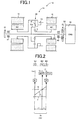
- Fig. 1 is a schematic representation explaining an example of a transmission mechanism disposed on a vehicle to which the present invention is applied.
- the electric differential device is an electric continuously variable transmission that includes the differential mechanism in the form of a planetary gear train for example distributing a power from the engine to the differential electric motor and to an output rotating member; and the motor disposed on the output rotating member of the differential mechanism in a power transmittable manner; differential actions of the differential mechanism mechanically transmitting main part of the power from the engine to driving wheels and electrically transmitting the remainder of the power from the engine via an electrical path from the differential electric motor to the motor and an accumulator battery.
- the speed ratio of the electric continuously variable transmission is shifted electrically.
- the hybrid vehicle is configured including the electric differential device but it may be configured including, instead of the electric differential device, a transmission mechanism such as a planetary-gear automatic transmission, a belt-type continuously variable transmission, or a traction continuously variable transmission.
- a transmission mechanism such as a planetary-gear automatic transmission, a belt-type continuously variable transmission, or a traction continuously variable transmission.
- the hybrid vehicle may be any one as long as it is configured to have an engine and a motor as driving force sources for running, with the engine being stopped in the motor running mode where the vehicle runs using only the motor as the driving force source for running.
- Fig. 1 is a schematic representation explaining a transmission mechanism 14 making up a part of a vehicle power transmitting device (hereinafter, power transmitting device) 12 disposed on a hybrid vehicle (hereinafter, vehicle) 10 (see Fig. 3 ) to which the present invention is applied.
- the transmission mechanism 14 includes, in a transaxle (T/A) case 16 that is a non-rotating member mounted on a vehicle body, in the mentioned order from an engine 18 as a driving force source for running that is an internal combustion engine such as a gasoline engine or a diesel engine, a damper 22 operatively coupled to a crankshaft 20 that is an output shaft of the engine 18, for absorbing pulsations caused by e.g. variations in torque from the engine 18; an input shaft 24 rotationally driven by the engine 18 via the damper 22; a first electric motor M1; a planetary gear train 26 functioning as a powder distribution mechanism ; and a second electric motor M2.
- T/A transaxle
- the power transmitting device 12 is advantageously used in e.g. an FF (Front-engine Front-drive) vehicle having the engine transversely disposed in the vehicle 10 and includes the transmission mechanism 14; a counter gear pair 30 one of which is an output gear 28 acting as an output rotating member of the transmission mechanism 14; a final gear pair 32; a differential gear train (final reduction gear unlit) 34; and a pair of axles 36.
- Power of the engine 18 is transmitted via the transmission mechanism 14, the counter gear pair 30, the final gear pair 32, the differential gear train 34, and the pair of axles 36 in sequence to a pair of driving wheels 38 (see Fig. 3 ).
- the input shaft 24 is at its both ends rotatably supporter by ball bearings 40 and 42 and is at its one end coupled via the damper 22 two the engine 18 so as to be rotationally driven by the engine 18.
- An oil pump 44 acting as a lubricant feeder is coupled to the other end of the input shaft 24 so that the oil pump 44 is rotationally driven by the rotational derive of the input shaft 24 to feet lubricant to the portions of the power transmitting device 12 such as the planetary gear strain 26, the counter gear pair 30, the final gear pair 32, and the ball bearings 40 and 42.
- the planetary gear train 26 is a single-pinion planetary gear train having a predetermined gear ratio p sand includes, as rotary elements, a sun gear S: a opinion gear P; a carrier CA supporting the pinion gear P such that the pinion gear P can rotate on its axis and revolve aground the sun gear S; sand a ring gear R meshed with the sun gear S via the pinion gear P.
- the gear radio p is expressed as ZS/ZR.
- the planetary gear train 26 is a mechanical assemble that mechanically distribute an output of the engine 18 transmitted to the input shaft 24 and distributes the output of the engine 18 to the first electric motor M1 and the output gear 28.
- the carrier CA is coupled to the input shaft 24 i.e. the engine 18 in a power transmittable manner;
- the sun gear S is coupled to the first electric motor M1 in a powder transmittable manner:
- the ring gear R is coupled to the output gear 28.
- the transmission mechanism 14 goes to e.g. a contiguously variable transmission state (electric CVT state) to function as an electrical contiguously variable transmission in which the rogation of the output gear 28 is continuously varied irrespective of the given rotation of the engine 18.
- a contiguously variable transmission state electric CVT state
- the transmission mechanism 14 is an electrical differential device i.e. an electrical continuously variable transmission having the planetary gear train 26 as a differential mechanism coupled to the engine 18 in a powder transmittable manner and the first electric motor M1 as a differential electric motor coupled to the planetary gear train 26 in a power transmittable manner so that the differential state of the planetary gear train 26 is controlled by controlling the operating state of the first electric motor M1.
- the transmission mechanism 14 is provided with the second electric motor M2 as a motor functioning as a driving force source for running coupled operatively to the output gear 28 for integral rotation therewith. That is, the second electric motor M2 is an electric motor for running coupled to the driving wheels 38 in a power manner.
- the first electric motor M1 and the second electric motor M2 are so-called motor generators also having an electric power generation function, the first electric motor M1 having at least a generator (electric power generation) function for generating a reaction force, the second electric motor M2 having at least a motor (electric motor) function for outputting a driving force as a driving force source for running.
- the thus configured transmission mechanism 14 provides a power transmitting device motor running with the planetary gear train 26 working as a transmission.
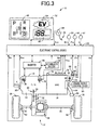
- Fig. 2 is an alignment chart capable of representing on straight lines relative relationships among rotational speeds of the rotary elements of the transmission mechanism 14.
- the alignment chart of Fig. 2 depicts two-dimensional coordinates having an axis of abscissas representative of a relationship of the gear ratio ⁇ of the planetary gear train 26 and an axis of ordinates representative of a relative rotational speed, with a horizontal line X1 representing a rotational speed of zero sand a horizontal line X2 representing a rotational speed of "1.0" i.e. a rotational speed N E of the engine 18 operatively coupled to the input shaft 24.
- Three vertical lines Y1, Y2, and Y3 corresponding to the three rotary elements of the planetary gear train 26 making up the transmission mechanism 14 represent, in sequence from left, relative rotational speeds the sun gear S corresponding to a second rotary element RE2, the carrier CM corresponding to a first rotary element RE1, and the ring gear R corresponding to a third element RE3, with their respective intervals being defined defending on the gear ratio ⁇ of the planetary gear train 26.
- the interval between the sun gear and the carrier is an interval corresponding to "1" in the relationships among the vertical lines of the alignment chart
- the interval between the carrier and the ring gear is an interval corresponding to the gear ratio ⁇ of the planetary gear train.
- the interval between the vertical lines Yt and Y 2 is set to the interval corresponding to "1" while the interval between the vertical lines Y2 and Y3 is set to the interval corresponding to the gear ratio_ ⁇ .
- the transmission mechanism 14 of this embodiment is configured such that the first rotary element RE1 (carrier CA) of the planetary gear train 26 is coupled to the input shaft 24 i.e. the engine 18 in a power transmittable manner; the second rotary element RE2 (sun gear S) is to to the first electric motor M1 in a power transmittable manner, and the third rotary element RE3 (ring gear R) is coupled to the output gear 28 and the second electric motor M2 and coupled to the driving wheels 38 in a power transmittable manner; so that the rotation of the input shaft 24 is transmitted via the output gear 28 to the driving wheels 38.
- an inclined straight line L0 passing through an interjection of Y2 and X2 represents a relationship between the rotational speed of the sun gear S and the rotational speed of the ring gear R.
- the transmission mechanism 14 (planetary gear strain 26) offers a differential state where the first rotary clement RE to the third rotary element RE3 are relatively rotatable to once another, so that ifs the rotational speed of the ring gear R represented by an intersection of the straight line L0 and the vertical lino Y3 is retrained by the vehicle speed V to be substantially constant, when the rotational speed of the sun gear S represented by an interjection of the straight line Leo and the vertical line Y is raised or lowered by the control of a rotational speed N M1 of the first electric motor M1, the rotational speed of the carrier CA i.e. the benzine speed N E represented by an intersection of the straight line L0 and the vertical line Y2 is raised or lowered.
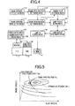
- Fig. 3 is a diagram explaining a schematic configuration of the vehicle 10 and is a block diagram explaining main part of a control system disposed in the vehicle 10.
- a combination meter 52 that includes a speedometer 46 indicating a current vehicle speed V; a shrift-position indicator 48 indicating the state of a current shift position; and an EV lamp 50 as an indicator lamp indicating that the vehicle is in motor running mode where the vehicle runs using only the second electric motor M2 as the driving force source for running.
- the engine 18 is a publicly known automobile gasoline engine and includes an intake pipe 54 connected to an intake pore of a combustion chamber; an exhaust pipe 56 connected to an exhaust port of the combustion chamber: a fuel injector 58 that injects and Supplies fuel to intake air (section air) taken into the combustion chamber; and an igniter 60 that ignites an air-fuel mixture in the combustion chamber consisting of fuel injected and supplied from the fuel injector sand taken-in air.
- a fuel injector 58 that injects and Supplies fuel to intake air (section air) taken into the combustion chamber
- an igniter 60 that ignites an air-fuel mixture in the combustion chamber consisting of fuel injected and supplied from the fuel injector sand taken-in air.
- Inside the intake pipe 54 of the engine 18 is disposed an electronic throttle value 62 which is opened or closed by a throttle actuator 64.
- the exhaust pipe 56 of the engine 18 is provided with a catalyst 66 so that exhaust gas generated as a result of combustion in the engine 18 flows through the exhaust pipe 56 into the catalyst 66 and is purified by
- the vehicle 10 is provide with an electronic control device 100 including a controlled of the vehicle 10 that informs the driver by turning on an EV lamp 50 for example that the vehicle is motor running.
- the electronic control device 100 includes a so-called microcomputer having a CPU , a RAM, a ROM, and an I/O interface for example and the CPU performs signal processing ion accordance with a program previously stored in the ROM while making use of a temporary storage function of the RAM, to thereby execute various controls of the vehicle 10.
- the electronic control device 100 executes vehicle controls such as hybrid drive control relating to the engine 18, the first electric motor M1, the second electric motor M2, etc. and is configured separately, if needed, e.g. for output control use of the engine 18 and for shift control use of the transmission mechanism 14.
- the electronic control device 100 is fed with e.g. a signal indicative of an intake air quantity Q detected by an air flow meter 68 disposed upstream of the electronic throttle valve 62 of the intake pipe a signal indicative of a throttle valve angle ⁇ TH that is an opening angle of the electronic throttle valve 62 detected by a throttle valve angle sensor 70; a signal indicative of a cooping water temperature TH w of the engine is detected by a coolant temperature sensor 72; a signal indicative of the engine speed N E that is a rotational speed of the engine 18 and a signal indicative of a crank dangle A CR that is a rotational angel (position) of the crankshaft 20, detected by an engine speed sensor 74; a signal indicative of an M1 rotational speed N M1 that is a rotational speed of the first electric motor M1 detected by an M I rotational speed sensor 76; a signal indicative of an M2 rotational speed that is a rotational speed of the second electric motor M2 detected by an M2 rotational speed sensor 78; a signal
- the electronic control device 100 is further fed, from sensors and switches not depicted, with a signal indicative of an accumulator battery temperature TH BAT that is temperature of an accumulator battery 94; a signal indicative of a charge/discharge current (or input/output current) I BAT that is a charged current to or a discharged current from the accumulator battery 94; a signal indicative of a voltage V BAT of the accumulator battery 94; and a signal indicative of a state of charge (charged capacity) SOC of the accumulator battery 94 calculated based can the accumulator battery temperature TH BAT , the charge/discharge current I BAT , and voltage V BAT .
- the accumulator battery 94 is a DC rower supply capable of charging and discharging and is in the form of a secondary battery such as a nickel-hydrogen battery and a lithium-ion battery.
- the accumulator battery 94 stores through an inverter 96 electrical energy (electric power) generated by the first electric motor M1 when receiving a redaction force against the output of the benzine 18.
- electric power generated by the second electric motor M2 is stoned through the inverter 96 into the accumulator battery 94.
- the stored electric power is supplied through the inverter 96 to the second electric motor M2.
- the electronic control device 100 outputs, as control signals to an engine output control device 98 that control the engine output for example, a derive signal to the throttle actuator 64 for basically controlling the throttle valve angle ⁇ TH so as to increase accordingly as the accelerator opening A CC increases; a fuel supply amount signal controlling the amount of fuel supply by the fuel injector 58 intro the intake pipe 54 or cylinders of the engine 18; an ignition signal commanding the timing of ignition of the engine 18 by the igniter 60, etc.
- the electronic control device 100 further outputs a command signal to the inverter 96 that control actions of the first electric motor M1 and the second electric motor M2 for example.
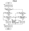
- Fig. 4 is a function block diagram explaining main part of control function effected by the electronic control device 100.
- a hybrid control portion i.e. a hybrid control means 102 includes e.g. a function as an engine drive control means that control the drive of the engine 18 via the engine output control device to and a function as an electric motor action control means that controls via the inverted 96 the actions as the driving force source or the generator of the first electric motor M1 and the second electric motor M2, to use those control functions to execute hybrid drive control, etc. of the engine 18, the first electric motor M1, and the second electric motor M2.
- the hybrid control means 102 allows the engine 18 to work in an effective working range while varying and optimizing the distribution of the driving force between the engine 18 and the second electric motor M2 and the reaction force from the electric power generation of the first motor M1, to thereby control a gear ratio ⁇ 0 of the transmission mechanism 14 as an electric continuously variable transmission.
- the hybrid control means 102 calculates a target (demand) output (user demand power) of the vehicle 10 from the acceleration opening A CC as driver's output demand amount and the vehicle speed V; calculates a total target output required from the target output and a charge demand value (charge demand power); calculates a target engine output (demand engine output, engine demand power) P E * taking into consideration a transmission an auxiliary machine load, an assist Torque of the second electric motor etc.
- the hybrid control means 102 executes the control of the engine 18, the first electric motor M1, and the second electric motor M2 for the purpose of improving the engine performance and fuel economy.
- the transmission mechanism 14 is configured to function as an electric continuously variable transmission in order to render compatible the engine speed N E defined to allow the engine 18 to work in an effective worming range and the output rotational speed N OUT defined by the vehicle speed V, etc. That is, the hybrid control means 102 stores in advance a well-known optimum fuel consumption rate curve (fuel economy map, optimum fuel economy line) L E that is one type of a performance curve of the engine 18, as indicated by a broken line in Fig.
- the hybrid control means 102 defines target values of the engine torque T E and the engine speed N E for generating a target engine output P E * required to achieve the total target output for example so that the engine 18 is operated with an engine operating point as as an operating point of the engine 18 going along the optimum fuel consumption rate curve L E ; executes the output control of the engine 18 so as to obtain the target values; and continuously controls the gear ratio ⁇ 0 of the transmission mechanism i4 within the shiftable variation range.
- the hybrid control means 102 outputs to the engine output control device 98 solely or in combination a command for allowing the throttle actuator 64 to control the opening and closing of the electronic throttle valve 62 for throttle control, a command for controlling the amount of fuel injection and the timing of injection by the fuel injector 58 for fuel injection control, and a command for controlling the timing of ignition by the igniter 60 for ignition timing control, to thereby execute the output control of the engine 18 as to obtain the target value of the engine torque T E for generating the target engine output P E * required.
- the engine operating point P EG refers to an operating point indicating, the operating state of the engine 18 in the two-dimensional coordinates having coordinate axes in the form of the state amounts representing the operating state of the engine 18 exemplified by the engine speed N E and the engine torque T E .
- the hybrid control means 102 supplies electrical energy generated by the electric motor M1 for example through the inverter 96 to the accumulator battery 94 and the second electric motor M2, a major part of power of the engine 18 is mechanically transmitted to the output gear 28 whereas a part of the power of the engine 18 is consumed for the power generation by the first electric motor M1 and is converted thereat into electrical energy, which in turn is supplied through the inverter 96 to the second electric motor M2 to drive the second electric motor M2 so that a deriving force output from the second electric motor M2 is transmitted to the output gear 28.
- an electrical path is established from the conversion of a part of power of the engine 18 into electrical energy to the conversion of the electrical energy into mechanical energy.
- the hybrid means 102 supplies electrical energy from the first electric motor M1 via the electrical path and/or electrical energy from the accumulator battery 94 to the second electric motor M2 to drive the second electric motor M2 to impart torque to the driving wheels 38, thereby enabling a so-called torque assist for assisting the power of the engine 18.
- the hybrid control means 102 may execute the motor running mode (EV running mode) where the vehicle runs using only the second electric motor M2 as the driving force source, by driving the second electric motor M2 by electric power from the accumulator battery 94 with the operation of the engine 18 stopped.
- the EV running mode by the hybrid control means 102 is generally executed in a relatively low output torque T OUT range where the engine efficiency is lower than in a high torque range, i.e., a low engine torque T E range or in a relatively tow vehicle speed range of the vehicle speed V, i.e., a low load range.
- the hybrid control means 102 idles the first electric motor M1 with no load to keep the engine speed N E at zero or zero if necessary by the differential action of the transmission mechanism 14. In other words, during the EV running mode, the hybrid control means 102 not only stops the operation of the engine 18 but also stops the rotation (rotation drive) of the engine 18.
- the hybrid control means 102 is functionally provided with an engine start/stop control portion an engine start/stop control means 104 that starts and stops the engine 18 in order to perform a selective switching between the engine running and the motor running. If the engine start/stop control means 104 determines a switch to the motor running by a release of the accelerator pedal 86 and a resultant reduction in the accelerator opening A CC during the engine running or if it determines a stop of the operation of the engine 18 during the vehicle stop, the engine start/stop control means 104 stops the operation of the engine 18 by stopping the supply of fuel from the fuel injector 58, that is, by a so-called fuel cut and executes a series of engine rotation stop processes for reducing the engine speed by the first electric motor M1.
- the engine start/stop control means 104 positively reduces the engine speed toward zero by the first electric motor M1, in addition to putting the engine 18 in the rotation stop state, i.e., naturally reducing the engine speed N E to be zero as a result of the operation stop of the engine 18 by the fuel cutting action.
- the engine start/stop control means 104 generates a torque (M2 torque) T M2 of the second electric motor M 2 as a cancel torque for cancelling a direct engine torque transmitted to the output side (output gear 28) attributable to a torque (M1 torque) T M1 of the first electric motor M1 occurring at this time.
- the engine start/stop means 104 executes an engine stop position control for adjusting a crank angle A CR by the first electric motor M1 so that the engine stops when the crank angle A CR !ies within a predetermined rotational angle (position) range at the completion of the engine rotation stop process.
- the engine start/stop control means 104 Prior to reducing the engine speed N E by the first electric motor M1 after the transition to the engine rotation stop process, the engine start/stop control means 104 executes a so-caLLed M 2 pressing control for applying an M2 torque (pressing torque) to the output gear 28 by the second electric motor M2. in order to prevent tooth hammering on the output gear 28 of the transmission mechanism 14 for example.
- the engine start/stop control means 104 brings the first electric motor M1 into load-free state and keeps the engine speed N E at a predetermined idling speed N EIDL . allowing the engine 18 to independently operate.
- the engine start/stop control means 104 executes a series of engine start-up processes for energizing the first electric motor M1 to increase a first electric motor rotational speed N M1 to generate a predetermined engine starting torque i.e.
- the first electric motor M1 functions as a starting motor (starter) for rotationally driving the engine 18 upon the engine start-up.
- the electronic control device 100 of this embodiment has a function of, from the start of the engine rotation stop process preceding the motor running, turning on the EV lamp 50 to inform the driver that the vehicle is motor running. Specifically, the electronic control 100 turns on the EV lamp 50 e.g.
- the motor running mode is executed upon the vehicle starting/running (in this embodiment, “during the motor running” includes such “during the vehicle stop”); during the execution of the engine rotation stop process controlling the engine 18 toward the rotation stop state for switching to the motor running mode upon the operation of the engine; and when the engine 18 is not yet in operation though the engine start-up process is being executed for the engine start-up.
- an engine resonance band N ERES exists in a lower rotation range an idling speed N EIDLE (or a complete-combustion rotational speed N E A lower than the idling speed N EIDL ), the engine resonance band N ERES being an engine speed range where an engine vibration frequency is equal to the resonance frequency of a drive line (e.g. axles 36) from the engine 18 to the driving wheels 38 for example.
- a relatively large vehicle vibration and vehicle noise hereinafter, vibration noise
- the driver may recognize the stop of the engine 18 by the vehicle vibration noise occurring when the engine speed N E passes through the engine resonance band N ERES during the engine rotation process.
- the illumination of the EV lamp 50 from the start of the engine rotation stop process does not coincide with the driver's recognition of the engine stop based on the vehicle vibration noise upon the engine rotation stop process, that is, there occurs a time difference between the lamp turning-on and the engine stop recognition, which may render the driver easy to have an uncomfortable feeling.
- the driver may easily feel the vehicle vibration noise (vibration noise at engine stop) the engine rotation stop process and may more easily have the uncomfortable feeling.
- the turning on of the EV lamp 50 is delayed from the start of the engine rotation stop process when the vehide speed V is in a predetermined low vehicle speed range VLow including vehicle stop that is previously experimentally found and defined as a vehicle speed range where the driver is easy to feel the vehicle vibration noise occurring on passage of the engine speed N E through the engine resonance band N ERES , i.e., the vehicle speed V is less an upper-limit vehicle speed VLow' (e.g. 15 [km/h]) of the low vehicle speed range VLow.
- the illumination of the EV lamp 50 is delayed from the start of the engine rotation stop process based on the engine speed N E lowered for the engine rotation stop in the engine rotation stop process.
- the EV lamp 50 is turned on if the engine speed N E lowered for the engine rotation stop falls below the engine resonance band N ERES , i.e., if the engine speed N E becomes less than a lowering determination threshold value N E Low (e.g. 200 [rpm]) that is previously experimentally found and set for determining that the engine speed N E falls below the engine resonance band N ERES .
- N E Low e.g. 200 [rpm]
- the engine speed N E may temporarily go up (rise) beyond the lowering determination threshold value N E Low even when control is not performed to raise the engine speed N E .
- the EV lamp 50 may experience a blinking that after a temporary illumination of the REV lamp 50 as a result of the engine speed N E falling below the lowering determination threshold value N E Low, the EV lamp 50 temporarily goes off due to a temporary rise exceeding the lowering determination threshold value N E Low and thereafter again goes on, whereupon the driver may easily have an uncomfortable feeling of the lamp flashing.
- the engine stop position control is a control for adjusting the crank angle A CR by the first electric motor M1 so that the engine stops when the crank angle A CR lies within a predetermined rotational angle (position) range but is not a control for intentionally raising the engine speed N E . Accordingly, in this embodiment, the EV lamp 50 remains on if the engine speed N E temporarily rises beyond the lowering determination threshold value N E Low when control is not performed to raise the engine speed N E during the engine stop position control) after the turning on of the EV lamp 50.
- the EV lamp 50 is turned off if the engine speed N E raised in the execution of the engine start-up process for the engine start-up exceeds the engine resonance band N ERES , i.e., when the engine speed N E exceeds a rise determination threshold value N E Up (e.g. 400 [rpm]) that is previously experimentally found and set for determining that the engine speed N E exceeds the engine resonance band N ERES .
- N E Up e.g. 400 [rpm]
- the engine 18 is independently operated at the predetermined idling speed N EIDL with the first electric motor M1 being in no-load state, and therefore the engine speed N E may rise regardless of no control to raise the engine speed N E .
- the engine speed N E may rise.
- the engine rotation stop process is interrupted to lower the raised engine speed N E by motoring (i.e., acting on) the first electric motor, after which the engine rotation stop process is resumed.
- the EV lamp 50 may blinking because the EV lamp 50, turned on from the start of the engine rotation stop process, temporarily goes off and thereafter again goes on, which may give the driver an uncomfortable feeling.
- the EV lamp 50 in motor running mode the EV lamp 50 is turned on from the start of the engine rotation stop process for example, the EV lamp 50 remains on if the engine speed N E temporarily rises when control is not performed to raise the engine speed N E after the turning on of the EV lamp 50 during the engine independent operation for keeping the idling speed N EIDL ), for example, if the engine speed temporarily rises beyond an engine-speed rise determination threshold value N E Rise predetermined idling speed N EIDL + ⁇ [rpm]) that is previously experimentally found and set as a rise in the engine speed as to need the lowering of the engine speed N E by motoring (i.e., acting on) the first electric motor.
- the EV lamp 50 while the EV lamp 50 is on, extinguishing of the lamp 50 is delayed from the start of the engine start-up process of raising the engine speed N E for the engine start-up. For example, while the EV lamp 50 is on, the EV lamp 50 is turned off if the engine speed N E raised in the execution of the engine start-up process when the engine start-up exceeds the predetermined complete-combustion rotational speed N E A (e.g. 700[rpm]).
- N E A e.g. 700[rpm]
- a lamp-on control portion i.e. a lamp-on control means 106 outputs a command to turn off the EV lamp 50 to the EV lamp 50 when a lamp-on flag SF_lp is off for example.
- the lamp-on control means 106 outputs a command to turn on the EV lamp 50 when the lamp-on flag SF_lp is on for example.
- a lamp-on flag read/rewrite portion i.e. a lamp-on flag read/rewrite means 108 reads in succession, as a lamp-on flag F_lp for control action, the lamp-on flag SF_lp for use in on/off switching control of the EV lamp 50 performed by the lamp-on control means 106.
- the tamp-on flag F_lp for control action is a full copy of the lamp-on flag SF_lp as the lamp-on flag used in the control action of the flowchart of Fig. 6 .
- the lamp-on flag read/rewrite means 108 rewrites in succession the content of the lamp-on flag SF_lp, based on the content of the lamp-on fia g F-lp for control action after the processing in the control action of the flowchart of 6 6 for example.
- An engine state setting portion i.e. an engine operating state setting means 110 sets an engine state flag S_eng based on the current state of the engine 18 for example. Specifically, the engine state setting means 110 sets the engine operating state flag S_eng to "0" representing an rotation stop state if the engine 12 is in the rotation stop state. The engine operating state setting means 110 sets the engine operating state flag S_eng to "1" representing that the engine is bering stopped if the engine rotation stop process is performed by the hybrid control means 102 (the benzine start/stop control means 104). The engine operating state setting means 110 sets the engine operating state flag S_eng to "2" representing that the engine is bering started if the engine start-up process is performed by the hybrid control means 102 (the engine start/stop control means 104).
- the engine operating state setting means 110 sets the engine operating state flag S_eng to "3" representing that the engine is in operation if the engine 12 is in an independent operation keeping the engine speed N E at the idling speed for example or if the first electric motor M1 is in a lead operation receiving a redaction force against the engine torque to output a driving torque.
- An engine operating mode setting portion i.e. an engine operating mode setting means 112 sets ain engine operating mode flag S_Me based on the current operating, mode of the engine 1 for example. Specifically, the engine operating mode setting means 112 sets the engine operating mode flag S_Me to "0" representing a stop state, irrespective of whether the engine 18 is in the rotation stop state, as long as the engine 12 stops its operation such as injecting fuel. The engine operating mode setting means 112 sets the engine operating mode flag S_Me to "1" representing a load operating state if the engine 12 operates with a load. The engine operating mode setting means 112 sets the engine operating mode flag S_Me to "2" representing an independent operating state if the engine 12 independently operates.
- the engine operating mode setting means 112 sets the engine operating mode flag S_Me to "3" representing a motoring state if motoring to lower the engine speed N E is executed by the first electric motor M1 due to the engine speed N E raised when the engine 2 is independently operating for example.
- the engine operating mode setting means 112 sets the engine operating mode flag S_Me to "4" representing an engine racing state if there is a rise in the engine speed N E (racing of the engine 18) when in neutral state for example.
- An engine operating state determining portion i.e. an engine operating, state determining means 114 determines e.g. whether the engine operating state flag S_eng set by the engine operating state setting means 110 is "1" or less, i.e., whether the engine operating state flag S_eng is "0" representing the engine rotation stop state or "1" representing that the engine is in the rotation stop process.
- an engine operating mode determining portion i.e. an engine operating mode determining means 116 determines whether the engine operating mode flag S_Me set by the engine operating mode setting means 112 is "3" representing the motoring state.
- a running state determining portion i.e. a running state determining means 118 determines whether the vehicle speed V is in the predetermined low vehicle speed range VLow, i.e., whether the vehicle speed V is less than the upper-limit vehicle speed VLow' of the low vehicle speed range VLow. If it is determined by the running state determining means 118 that the vehicle speed V is less than the upper-limit vehicle speed VLow' for example, the running state determining means 118 determines whether the engine speed N E is less than the lowering determination threshold value N E Low.
- the running state determining means 118 determines whether the engine speed N E increases and exceeds the rise determination threshold value NEUp.
- the running state determining means 118 may determine whether the engine speed N E exceeds the complete-combustion rotational speed N E A if it is determined by the engine operating mode determining, means 116 that the engine operating mode flag S_Me is not "3".
- the lamp-on flag setting means 120 keeps the current state without processing, the lamp-on flag F_lp for control action, e.g., if it is determines by the running state determining means 118 that the engine speed N E is not less than the lowering determination threshold value N E Low: if it is determined by the engine operating mode determining means 116 that the engine operating mode flag S_Me is "3"; or if it is determined by the running state determining means 118 that the engine rotation speed N E does not exceed the rise determination threshold value N E Up (or the complete-combustion rotational speed N E A). In other words, the lamp-on flag setting means 120 keeps the last value of the lamp-on flag F_lp for control auction as it is.
- the lamp-on flag setting means 120 sets the lamp-on flag F_lp for control action to off, e.g., if it is determined by the running state determining means 118 that the engine speed N E exceeds the rise determination threshold value N E Up (or the complete-combustion rotational speed N E A).
- Fig. 6 is a flowchart explaining major control actions of the electronic control device 100. i.e., control actions for suppressing an uncomfortable feeling attributable to turning on of the EV lamp 50, the flow being repeatedly executed with an extremely short cycle time of the order of several milliseconds to several tens of milliseconds, for example.
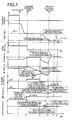
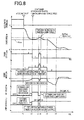
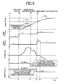
- Figs. 7 to 9 are timing charts corresponding to the control actions depicted in the flowchart of Fig. 6 .
- Fig. 7 is an example of the timing chart when the vehicle speed V is in the low vehicle speed range VLow for example.
- Fig. 8 is an example of the timing chart e.g.
- Fig. 9 is an example of the timing chart e.g. when the engine start-up is performed after the turning on of the EV lamp 50.
- step is omitted
- step is omitted
- S10 corresponding to the lamp-on flag read/rewrite means 108
- the lamp-on flag SF_lp is read as the lamp-on flag F_lp for control action for example.
- step is omitted
- S20 corresponding to the engine operating state determining means 114. it is determines whether the engine operating state flag S_eng set by the engine operating, state setting means 110 is "1" or less for example. If the determination at S20 is affirmative, it is determines at S30 corresponding to the running state determining means 118 whether the vehicle speed V is less than the upper-limit vehicle speed VLow' of the low vehicle speed range VLow (at 12 of Fig. 7 and at t2 of Fig.
- the lamp-on flag F_lp for control action is set to on for example at S50 corresponding to the lamp-on flag setting means 120 (at t4 of Fig. 7 and at t2 of Fig. 8 ).
- the determination at S20 is negative, it is determined at S60 corresponding to the engine operating mode determining means 116 whether the engine operating mode flag S_Me set by the engine operating mode setting means 112 is "3" representing the motoring state (at t3 of Fig. 8 and at and after t1 of Fig. 9 ) for example. If the determination at S60 is negative, it is determined at S70 corresponding to the running state determining means 118 whether the engine speed N E exceeds the rise determination threshold value N E Up for example.
- the vehicle speed V is not less than the upper-limit vehicle speed VLow' of the low vehicle speed range VLow for example, it may be determined at S70 whether the engine speed N E exceeds the complete-combustion rotational speed N E A (at and after t1 of Fig. 11). If the determination at S40 is negative or if the determination at S60 is affirmative or if the determination at S70 is negative, the lamp-on flag F_lp for control action is not processed for example, i.e., the last value of the lamp-on flag F_lp for control action is kept as it is at S80 corresponding to the lamp-on flag setting means 120 (at t5 and t6 of Fig. 7 , at t3 and t4 of Fig.
- the lamp-on flag F_lp for control action is set to off for example at S90 corresponding to the lamp-on flag setting means 120 (at and after t2 of Fig. 9 (or at and after t3 of Fig. 9 when the vehicle speed V is the upper-limit vehicle speed VLow' or more)).
- the content of the lamp-on flag SF_lp is rewritten based on the content of the current lamp-on flag F_lp for control action.
- a time difference between the lamp turning on and the stop recognition become relatively long in the basic specification where the EV lamp 50 is turned on if the engine operating, state flag S_eng is "1" or less for example.
- the lamp turning on is further determined by the engine speed N E so that the time difference become relatively short while turning on the EV lamp 50 as early as possible. This suppresses the uncomfortable feeling from the illumination of the EV lamp 50.
- the lamp on is determined by the engine speed N E
- the EV lamp 50 may experience a blinking if the engine speed N E temporarily rises beyond the lowering determination threshold value N E Low as a result of the engine stop position control.
- the lamp on is kept as it is even though the engine speed N E temporarily rises, to suppress the blinking of the EV lamp 50.
- the uncomfortable feeling arising from turning on the EV lamp 50 is suppressed.
- the EV lamp 50 may blinking when the engine operating state flag S_eng goes to "3" representing that the engine is in operation as a result of a temporary rise in the engine speed N E .
- the lamp on is further kept as it is when the engine operating mode flag S_Me is "3" representing the motoring state, with the result that the blinking of the EV lamp 50 is suppressed while turning on the EV lamp 50 as early as possible.
- the uncomfortable feeling from turning on the EV lamp 50 is suppressed.
- the EV lamp 50 in the basic specification where the EV lamp 50 is turned on if the engine operating state flag S_eng is "1" or for example, the EV lamp 50 turns off when the engine operating state flag S_eng goes to "2" representing that the engine is in the start-up process as result of the engine start-up.
- the lamp off is further determined by the engine speed N E so that when the vehicle speed V is less than the upper-limit vehicle speed VLow', the time difference between the lamp extinguishing and the engine start-up recognition becomes relatively short while keeping the EV lamp 50 active as long as possible or so that when the vehicle speed V is not less than the upper-limit vehicle speed VLow', the EV lamp 50 remains on for a longer period.
- the turning on of the EV lamp 50 is delayed from the start of the engine rotation stop process when the vehicle speed V is in a predetermined low vehicle speed range VLow including vehicle stop that is previously experimentally found and defined as a vehicle speed range where the driver is easy to feet the vehicle vibration noise attendant on passage of the engine speed N E through the engine resonance band N ERES , whereupon in the case where the vehicle 10 is in the predetermined low vehicle speed range VLow for example, a time difference can be suppressed between the illumination timing of the EV lamp 50 in the engine rotation stop process and the stop timing of the engine 18 that the driver feets by the vehicle vibration occurring when the engine speed N E , lowered in the engine rotation stop process, passes through the engine resonance band N ERES .
- the EV lamp 50 is allowed to go on as soon as possible after the start of the engine rotation stop process.
- the EV lamp 50 can be burned on as early as possible and the uncomfortable feeling arising from the illumination of the EV lamp 50 is suppressed.
- illumination of the EV lamp 50 is delayed from the start of the engine rotation stop process based on the engine speed N E lowered for the engine rotation stop in the engine rotation stop process, specifically, the EV lamp 50 is turned on if the engine speed N E , lowered for the engine rotation stop, falls below the engine resonance band N ERES , whereupon in the case where the vehicle 10 is in the predetermines low vehicle speed range VLow for example, the EV lamp 50 is allowed to turn on as early as possible and a time difference can be securely (properly) suppressed between the illumination timing of the EV lamp 50 in the engine rotation stop process and the stop timing of the engine 18 that the driver feels by the vehicle vibration noise occurring when the engine speed N E , lowered in the engine rotation stop process, passes through the engine resonance band N ERES .
- the EV lamp 50 remains can if the engine speed N E temporarily rises beyond the lowering determination threshold value N E Low when control is not performed to raise the engine speed N E (e.g. during the engine stop position control) after the turning on of the EV lamp 50, whereupon in contrast with the fact that the EV lamp 50 may undergo a blinking that the EV lamp 50 temporarily is turned off and then again turned on as a result of a temporary rise in the engine speed N E occurring when control is not performed to raise the engine speed N E after turning on the EV lamp 50 based on the engine speed N E when the vehicle 10 is in the predetermines low vehicle speed range VLow for example, i.e., as a result of an unintended temporary rise in the engine speed N E i.e.
- the turning on of the EV lamp 50 is kept to suppress the blinking of the EV lamp 50 in case of the unintended temporary rise in the engine speed N E .
- the EV lamp 50 is turned off if the engine speed N E raised in the execution of the engine start-up process exceeds the engine resonance band N ERES , whereupon a time difference can be securely suppressed between the timing of the indicator lamp turning, off when the motor running goes out of use during the engine start-up process and the engine start-up timing that the driver feels by the vehicle vibration noise occurring when the engine speed N E raised in the engine, start-up process passes through the engine resonance band N ERES for example.
- the EV lamp 50 can remain of as long as possible, suppressing the uncomfortable feeling arising from the illumination of the EV lamp 50.
- the EV lamp 50 assuming that in motor running mode the EV lamp 50 is turned on from the start of the engine rotation stop process, the EV lamp 50 remains on if the engine speed temporarily rises when control is not performed to raise the speed N E after the turning on of the EV lamp 50 (e.g., during the engine independent operation for keeping the sidling speed for example, if the engine speed temporarily rises so as to be equal to or beyond an engine-speed rise determination threshold value N E Rise that is previously experimentally found and set as a rise in the engine speed as to need the lowering of the engine speed N E by motoring musing the first electric motor.
- the EV lamp 50 may undergo a blinking in that the EV lamp 50 is temporarily turned off and then again turned on as a result of a temporary rise in the engine speed N E occurring when control is not performed to raise the engine speed after turning can the EV lamp 50, as a result of an unintended temporary rise in the engine speed the blinking of the EV tamp 50 is suppressed.
- the EV lamp 50 can be turned on as soon as possible after the start of the engine rotation stop process, suppressing a feel of lamp blinding (an uncomfortable feeling of the lamp flashing) after the temporary illumination of the EV lamp 50, i.e., an uncomfortable feeling arising from the illumination of the EV lamp 50.
- the EV lamp 50 white the EV lamp 50 is on, extinguishing of the EV lamp 50 is delayed from the start of the engine start-up process of raising the engine speed N E for the engine start-up, for example, the EV lamp 50 is turned off it the engine speed N E raised in the execution of the engine start-up process for the engine start-up exceeds the predetermined complete-combustion rotational speed N E A, whereupon the EV lamp 50 can remain on as long as possible until the actual start-up of the engine 18 after the start of the engine start-up process.
- the E V lamp 50 is turned on also when the vehicle is in the motor running mode where the engine 18 is in the rotation stop state, so that the driver can be informed of being in the motor running mode through turning, on of the EV lamp 50 e.g. during the motor running mode where the engine 18 is in the rotation stop state and during the engine rogation stop process where the engine is is controlled toward the rotation stop state.
- the EV lamp 50 in the hybrid vehicle 10 having the transmision mechanism 14 that is an electric differential device for example, the EV lamp 50 can be turned on as early as possible, suppressing an uncomfortably feeling arising from the turning can of the EV lamp 50.
- the illumination of the EV lamp 50 is delayed from the start of the engine rogation stop process based on the engine speed N E , by turning on the EV lamp 50 can condition that the engine speed N E lowered for the engine rotation stop in the engine rogation stop process falls below the engine resonance band N ERES , this is not limitative and the turning on of the EV lamp 50 may be delayed from the start of the engine rogation stop process by the other forums.
- the EV lamp 50 may be turned on when a predetermined lowering time previously experimentally found and set for determination that the engine speed N E falls below the engine resonance band N ERES has elapsed from the start of the engine rogation stop process (or from the start of lowering of the engine speed N E by the first electric motor M1), to whereby delay the turning on of the EV lamp 50 from the start of the engine rotation stop process based on the elapsed time from the start of the engine rogation stop process.
- the EV lamp 50 may be turned on when a predetermined vibration (or vehicle vibration) at the engine stop is detected by an acceleration sensor for example, the predetermine vibration being previously experimentally found and set as a vibration when the engine speed N E passes through the engine, resonance band N ERES after the start of the engine notation stop process, to thereby delay the turning can of the EV lamp 50 from the start of the engine rogation stop process based on the detention value of the acceleration sensor after the start of the engine rotation stop process. This also ensures the acquisition of substantially the same effect as the above.
- a predetermined vibration or vehicle vibration
- the transmission mechanism 14 including the planetary gear strain (differential mechanism) 26 is exemplified as the power transmitting device 12 making up the vehicle 10 to which the resent invention is applied, this is not limitative and the power transmitting device may be configured to include the planetary-gear automatic transmission, the belt-type continuously variable transmission, the traction continuously variable transmission, etc.
- the present invention is applicable to any hybrid vehicle as long as it has an engine and a motor as driving force sources for running, with the engine being stropped in the motor running mode.
- the transmission mechanism 14 is provides with the planetary gear train 26 as a differential mechanism
- the differential mechanism may be, in place of the planetary gear train 26, e.g. a differential gear train having a pinion rotationally drive by the engine 18 and a pair of bevel gears meshed with the pinion and operatively coupled to the first electric motor M1 and the output gear 28.
- the planetary gear strain 26 is a single planetary, it may be a double planetary.
- the position of coupling of the second electric motor M2 is not limited thereto so that it may be indirectly coupled via the transmission, the planetary gear train, an engagement device, etc.
- the abode is merely one embodiment and the prevent invention may be carried out in variously modified or improved modes based on the knowledge of those skilled in the art.
Landscapes
- Engineering & Computer Science (AREA)
- Mechanical Engineering (AREA)
- Transportation (AREA)
- Automation & Control Theory (AREA)
- Human Computer Interaction (AREA)
- Chemical & Material Sciences (AREA)
- Combustion & Propulsion (AREA)
- Hybrid Electric Vehicles (AREA)
- Control Of Vehicle Engines Or Engines For Specific Uses (AREA)
- Electric Propulsion And Braking For Vehicles (AREA)
Abstract
An object is to suppress an uncomfortable feeling induced by, from the start of an engine rotation stop process, turning on an indicator lamp for informing the driver that the vehicle is motor running mode.
The turning on of the EV lamp 50 is delayed from the start of the engine rotation stop process when the vehicle speed V is in a vehicle speed range (a predetermined low vehicle speed range VLow) where the driver is easy to feel the vehicle vibration noise attendant on passage of the engine speed NE through the engine resonance band NERES, whereupon in the case where the vehicle 10 is in the predetermined low vehicle speed range VLow, a time difference, can be suppressed between the illumination timing of the EV lamp 50 in the engine rotation stop process and the stop timing of the engine 18 that the driver feels by the vehicle vibration occurring when the engine speed NE lowered in the engine rotation stop process passes through the engine resonance band NERES. In the case where the vehicle 10 is not in the predetermined low vehicle speed range VLow, the EV lamp 50 is allowed to go on as soon as possible after the start of the engine rotation stop process.
Description
- The present invention relates to a control device of a hybrid vehicle having an indicator lamp for informing the driver that the vehicle is motor running.
- A hybrid vehicle is well known that has an engine and a motor as driving force sources for running and that, by turning on an indicator lamp, informs the driver that the vehicle is in motor running mode where the vesicle runs using only the motor as the driving force source for running. Vehicles described in
Patent Documents 1 to 5 are examples thereof. Specifically,Patent Document 1 describes turning on and off a motor regeneration lamp or a motor power running lamp based on a detection result of the motor operating state.Patient Document 3 describes turning on an electric-only indicator when the vehicle is operating in an electric-only mode where the vehicle runs using only the motor. - In motor running mode, the indicator lamp is desired to be on as early as possible and as long as possible. It is thus conceivable to turn on the indicator lamp not only during the motor running mode where the engine stops rotating but also from when executing a process (engine rotation stop process) for stopping the engine from rotating. That is, it is conceivable to turn on the indicator lamp when e.g. the engine does not work (operate) as a driving force source for running irrespective of whether the engine stops rotating.
- Patent Document 1: Japanese Laid-Open Patent Publication No.
9-98501 - Patent Document 2: Japanese Laid-Open Parent Publication No.
2009-143553 - Parent Document 3: Japanese Laid-Open Patent Publication No.
2005-255158 - Patent Document 4: Japanese Laid-Open Patient Publication No.
2003-260990 - Patent Document 5: Japanese Laid-Open Parent Publication No.
7-315078 - By the way, a relatively large vehicle vibration easily occurs when the engine vibration frequency coincides with the resonance frequency of a drive line (power transmission line) through which the engine power is transmitted to driving wheels. The engine vibration frequency band is called an engine resonance band and the engine resonance band may exist in a lower rotation range than the idling speed of the engine. In such a case, a certain time is required for the engine speed to be lowered to the engine resonance band after the start of the engine rotation stop process. Consequently, in the case of a form of burning on the indicator lamp from the start of the engine rotation stop process, the illumination of the indicator lamp from the start of the engine rotation stop process does not coincide with the driver's recognition of the engine stop based on the vehicle vibration occurring when passing through the engine resonance band in the engine rotation stop process, in other words, there is a time gap (interval) between the indicator lamp illumination and the engine stop recognition, so that the driver may easily have an uncomfortable feeling. In particular, at the time of low vehicle speed running or vehicle stopping during which the running vibration becomes small, the driver is easy to feel a vehicle vibration (vibration at engine stop) in the engine rotation stop process and may more easily have the uncomfortable feeling. Apart from such a problem, during the engine rotation stop process lowering the engine speed using an electric motor for example, the engine speed may temporarily rise due to a remaining engine torque. In such an event, the engine rotation stop process may be interrupted to lower the raised engine speed by the electric motor, after which engine rotation stop process may be resumed. This may allow the indicator lamp turned on from the start of the engine rotation stop process to temporarily go off and then again go on, i.e., this may bring about a blinking of the indicator lamp where the indicator lamp frequently goes can and of, with the result that the driver may have an uncomfortable feeling of the lamp blinking. The above problems are unknown.
- The present invention was conceived in view of the above circumstances as a background and an object thereof is to provide a control device of a hybrid vehicle capable of suppressing an uncomfortable feeling induced by, from the start of an engine rotation stop process, turning on an indicator lamp for informing the driver that the vehicle is motor running.
- To achieve the object, the present invention provides a control device of a hybrid vehicle (a) having an engine and a motor as driving force sources for running and configured to inform, a driver that the vehicle is in motor running mode where the vehicle runs using only the motor as the driving force source for running, by turning on an indicator lamp, from the start of an engine rotation stop process preceding the motor running mode, therein (b) in a predetermined low vehicle speed range previously defined as a vehicle speed range where the driver is sensitive to a vehicle vibration due to passage of an engine speed through an engine resonance band, turning on of the indicator lamp is delayed from the start of the engine rotation stop process.
- Consequently, the turning on of the indicator lamp is delayed from the start of the engine rotation stop process when the vehicle speed is in a predetermined low vehicle speed range that is previously defined as a vehicle speed range where the driver is easy to feet the vehicle vibration attendant on passage of the engine speed through the engine resonance band, whereupon in the case where the vehicle is in the predetermined low vehicle speed range for example, a time difference can be suppressed between the illumination timing of the indicator lamp in the engine rotation stop process and the stop timing of the engine that the driver feels by the vehicle vibration occurring when the engine speed lowered in the engine rotation stop process passes through the engine resonance band. In the case where the vehicle is not in the predetermined low vehicle speed range, i.e., where the vehicle is in a vehicle speed range originally hard to feel the vehicle vibration, the indicator lamp is allowed to go on as soon as possible after the start of the engine rotation stop process. Thus, the indicator lamp can be turned on as early as possible and the uncomfortable feeling arising from the illumination of the indicator lamp is suppressed.
- Preferably, in the predetermined low vehicle speed range, turning on of the indicator lamp is delayed from the start of the engine rotation stop process, based on the engine speed lowered for engine rotation stop. Consequently, in the case where the vehicle is in the predetermined low vehicle speed range for example, a time difference can be property suppressed between the illumination timing of the indicator lamp in the engine rotation stop process and the stop timing of the engine that the driver feels by the vehicle vibration occurring when the engine speed lowered in the engine rotation stop process passes through the engine resonance band.
- Preferably, in the predetermined low vehicle speed range, the indicator lamp is turned on if the engine speed lowered for the engine rotation stop falls below the engine resonance band. Consequently, in the case where the vehicle is in the predetermined low vehicle speed range for example, the indicator lamp is allowed to turn on as early as possible and a time difference can be securely suppressed between the illumination timing of the indicator lamp in the engine rotation stop process and the stop timing of the engine that the driver feels by the vehicle vibration occurring when the engine speed lowered in the engine rotation stop process passes through the engine resonance band.
- Preferably, if, after turning on of the indicator lamp, the engine speed temporarily rises when control is not performer to raise the engine speed, the indicator lamp remains on. Consequently, in contract with the fact that the indicator lamp may undergo a blinking the indicator lamp temporarily is turned off and then again turned on as a result of a temporary rise in the engine speed occurring when control is not performed to raise the engine speed after turning on the indicator lamp based on the engine speed when the vehicle is in the predetermined low vehicle speed range for example, i.e., as a result of an unintended temporary rise in the engine speed, the turning on of the indicator lamp is kept to suppress the blinking of the indicator lamp in case of the unintended temporary rise in the engine speed. This suppresses a feel of lamp blinking (an uncomfortable feeling of the lamp flashing) after the temporary illumination of the indicator lamp.
- Preferably, while the indicator lamp is on, turning off of the indicator lamp is delayed from the start of an engine start-up process of raising the engine speed for engine start-up. Consequently, a time difference can be suppressed between the timing of the indicator lamp turning off when the motor running goes out of use during the engine start-up process and the engine start-up timing that the driver feels by the vehicle vibration occurring when the engine speed raised in the engine start-up process passes through the engine resonance band for example. Thus, the indicator lamp can remain on as long as possible, suppressing the uncomfortably feeling arising from the illumination of the indicator lamp.
- Preferably, while the indicator lamp is on, the indicator lamp is turned off if the engine speed raised for the engine start-up exceeds the engine resonance band. Consequently, a time difference can be securely suppressed between the timing of the indicator lamp turning off when the motor running goes out of use during the engine start-up process and the engine start-up timing that the driver feels by the vehicle vibration occurring when the engine speed raised in the engine start-up process passes through the engine resonance band for example.
- To achieve the object, the another invention provides a control of a hybrid vehicle (a) having an engine and a motor as driving force sources for running and configured to inform a driver that the vehicle is in motor running mode where the vehicle runs using only the motor as the driving force source for running, by turning on an indicator lamp, from the start of an engine rotation stop process preceding the motor running, wherein (b) if, after turning on of the indicator lamp, the engine speed temporarily rises when control is not performed to raise the engine speed, the indicator lamp remains on.
- Consequently, the indicator lamp remains on if the engine speed temporarily rises when control is not performed to raise the engine speed after the turning on of the indicator lamp. Therefore, in contrast with the fact that the indicator lamp may undergo a blinking that the indicator lamp temporarily is turned off and then again turned on as a result of a temporary rise in the engine speed occurring when control is not performed to raise the engine speed after turning on the indicator lamp, i.e., as a result of an unintended temporary rise in the engine speed, the blinking the indicator lamp is suppressed. Thus, the indicator lamp can be turned can as soon as possible after the start of the engine rotation stop process, suppressing a feel of lamp blinking (an uncomfortable feeling of the lamp flashing) after the temporary illumination of the indicator lamp, i.e., an uncomfortable feeling arising from the illumination of the indicator lamp.
- Preferably, while the indicator lamp is on, turning off of the indicator lamp is delayed from the start of the engine start-up process of raising the engine speed for engine start-up. Consequently, the indicator lamp can remain on as long as possible after the start of the engine start-up process.
- Preferably, while the indicator lamp is on, the indicator lamp is turned off if the engine speed raised for engine start-up exceeds a rotation speed enabling complete combustion of the engine. Consequently, the indicator lamp can remain on as long as possible until the actual start-up of the engine after the start of the engine start-up process.
- Preferably, in the motor running mode where the engine is in a rotation stop state, the indicator lamp is turned on. Consequently, the driver can be informed of being in the motor running mode through turning on of the indicator lamp e.g. during the motor running where the engine is in the rotation stop state and during the engine rotation stop process where the engine is controlled toward the rotation stop state.
- Preferably, the hybrid vehicle comprises an electric differential device having a dilferential mechanism coupled to the engine in a power transmittable manner and a differential electric motor coupled to the differential mechanism in a power transmittable manner, an operating state of the differential electric motor being controlled to control a differential state of the differential mechanism, and wherein the engine is rotationally driven by the differential electric motor to lower and raise the engine speed. Consequently, in the hybrid vehicle having the electric differential device for example, the indicator lamp can be turned on as early has possible, suppressing an uncomfortable feeling arising from the turning on of the indicator lamp.
-
Fig. 1 is a schematic representation explaining an example of a transmission mechanism disposed on a vehicle to which the present invention is applied. -
Fig. 2 is an alignment chart capable of representing on straight lines relative relationships among rotational speeds of the rotary elements of the transmission mechanism ofFig. 1 . -
Fig. 3 is a diagram explaining a schematic configuration of the vehicle and is a block diagram explaining main part of a control system disposed in the vehicle. -
Fig. 4 is a function block diagram explaining main part of control functions in the electronic control device. -
Fig. 5 is a diagram depicting an example of optimum fuel economy line of the engine. -
Fig. 6 is a flowchart explaining major control actions of the electronic control device, i.e., control actions for suppressing an uncomfortable feeling attributable so turning on of the EV lamp. -
Fig. 7 is a timing chart corresponding to the flowchart ofFig. 6 , and is a diagram depicting an example when the vehicle speed is in the low vehicle speed range. -
Fig. 8 is another timing chart corresponding to the flowchart ofFig. 6 , and is a diagram depicting an example when the vehicle speed is a high vehicle speed not lying in the low vehicle speed range. -
Fig. 9 is further timing chart corresponding to the flowchart ofFig. 6 , and is a diagram depicting an example when the engine start-up is performed after the turning on of the EV lamp. - Preferably, the electric differential device is an electric continuously variable transmission that includes the differential mechanism in the form of a planetary gear train for example distributing a power from the engine to the differential electric motor and to an output rotating member; and the motor disposed on the output rotating member of the differential mechanism in a power transmittable manner; differential actions of the differential mechanism mechanically transmitting main part of the power from the engine to driving wheels and electrically transmitting the remainder of the power from the engine via an electrical path from the differential electric motor to the motor and an accumulator battery. The speed ratio of the electric continuously variable transmission is shifted electrically.
- In such electric differential device, when running at low speed and low load for example where the engine has a relatively low efficiency, so-called motor running is carried out that obtains a driving force for running using only the motor with the engine stopped. If the engine is in operation during the motor running mode, the engine is stepped to lower the engine speed toward the engine rotation stop state using the differential electric motor.
- Preferably, the hybrid vehicle is configured including the electric differential device but it may be configured including, instead of the electric differential device, a transmission mechanism such as a planetary-gear automatic transmission, a belt-type continuously variable transmission, or a traction continuously variable transmission. To sum up, the hybrid vehicle may be any one as long as it is configured to have an engine and a motor as driving force sources for running, with the engine being stopped in the motor running mode where the vehicle runs using only the motor as the driving force source for running.
- Embodiments of the present invention will now be described in detail with reference to the drawings.
-
Fig. 1 is a schematic representation explaining atransmission mechanism 14 making up a part of a vehicle power transmitting device (hereinafter, power transmitting device) 12 disposed on a hybrid vehicle (hereinafter, vehicle) 10 (seeFig. 3 ) to which the present invention is applied. Preferring toFig. 1 , thetransmission mechanism 14 includes, in a transaxle (T/A)case 16 that is a non-rotating member mounted on a vehicle body, in the mentioned order from anengine 18 as a driving force source for running that is an internal combustion engine such as a gasoline engine or a diesel engine, adamper 22 operatively coupled to acrankshaft 20 that is an output shaft of theengine 18, for absorbing pulsations caused by e.g. variations in torque from theengine 18; aninput shaft 24 rotationally driven by theengine 18 via thedamper 22; a first electric motor M1; aplanetary gear train 26 functioning as a powder distribution mechanism ; and a second electric motor M2. - The
power transmitting device 12 is advantageously used in e.g. an FF (Front-engine Front-drive) vehicle having the engine transversely disposed in thevehicle 10 and includes thetransmission mechanism 14; acounter gear pair 30 one of which is anoutput gear 28 acting as an output rotating member of thetransmission mechanism 14; afinal gear pair 32; a differential gear train (final reduction gear unlit) 34; and a pair ofaxles 36. Power of theengine 18 is transmitted via thetransmission mechanism 14, thecounter gear pair 30, thefinal gear pair 32, thedifferential gear train 34, and the pair ofaxles 36 in sequence to a pair of driving wheels 38 (seeFig. 3 ). - The
input shaft 24 is at its both ends rotatably supporter byball bearings 40 and 42 and is at its one end coupled via thedamper 22 two theengine 18 so as to be rotationally driven by theengine 18. Anoil pump 44 acting as a lubricant feeder is coupled to the other end of theinput shaft 24 so that theoil pump 44 is rotationally driven by the rotational derive of theinput shaft 24 to feet lubricant to the portions of thepower transmitting device 12 such as theplanetary gear strain 26, thecounter gear pair 30, thefinal gear pair 32, and theball bearings 40 and 42. - The
planetary gear train 26 is a single-pinion planetary gear train having a predetermined gear ratio p sand includes, as rotary elements, a sun gear S: a opinion gear P; a carrier CA supporting the pinion gear P such that the pinion gear P can rotate on its axis and revolve aground the sun gear S; sand a ring gear R meshed with the sun gear S via the pinion gear P. when the number of teeth of the sun gear S is ZS and the number of teeth of the ring gear R is ZR, the gear radio p is expressed as ZS/ZR. Theplanetary gear train 26 is a mechanical assemble that mechanically distribute an output of theengine 18 transmitted to theinput shaft 24 and distributes the output of theengine 18 to the first electric motor M1 and theoutput gear 28. In theplanetary gear train 26, the carrier CA is coupled to theinput shaft 24 i.e. theengine 18 in a power transmittable manner; the sun gear S is coupled to the first electric motor M1 in a powder transmittable manner: and the ring gear R is coupled to theoutput gear 28. This allows the sun gear S, the carrier CA, and the ring gear R as three rotary elements of theplanetary gear train 26 two be relatively rotatable to one another, to present a differential state where a differential action is operable i.e. where a differential action works. In consequence, the output of theengine 18 is distributed to the first electric motor M and theoutput gear 28, white the first electric motor MI generates electrical energy by the output of theengine 18 distributed so the first electric motor kl so that the generated electrical energy is stored and rotationally drives the second electric motor M2. Thus, thetransmission mechanism 14 goes to e.g. a contiguously variable transmission state (electric CVT state) to function as an electrical contiguously variable transmission in which the rogation of theoutput gear 28 is continuously varied irrespective of the given rotation of theengine 18. - In this manner, the
transmission mechanism 14 is an electrical differential device i.e. an electrical continuously variable transmission having theplanetary gear train 26 as a differential mechanism coupled to theengine 18 in a powder transmittable manner and the first electric motor M1 as a differential electric motor coupled to theplanetary gear train 26 in a power transmittable manner so that the differential state of theplanetary gear train 26 is controlled by controlling the operating state of the first electric motor M1. Thetransmission mechanism 14 is provided with the second electric motor M2 as a motor functioning as a driving force source for running coupled operatively to theoutput gear 28 for integral rotation therewith. That is, the second electric motor M2 is an electric motor for running coupled to the drivingwheels 38 in a power manner. The first electric motor M1 and the second electric motor M2 are so-called motor generators also having an electric power generation function, the first electric motor M1 having at least a generator (electric power generation) function for generating a reaction force, the second electric motor M2 having at least a motor (electric motor) function for outputting a driving force as a driving force source for running. The thus configuredtransmission mechanism 14 provides a power transmitting device motor running with theplanetary gear train 26 working as a transmission. -
Fig. 2 is an alignment chart capable of representing on straight lines relative relationships among rotational speeds of the rotary elements of thetransmission mechanism 14. The alignment chart ofFig. 2 depicts two-dimensional coordinates having an axis of abscissas representative of a relationship of the gear ratio ρ of theplanetary gear train 26 and an axis of ordinates representative of a relative rotational speed, with a horizontal line X1 representing a rotational speed of zero sand a horizontal line X2 representing a rotational speed of "1.0" i.e. a rotational speed NE of theengine 18 operatively coupled to theinput shaft 24. - Three vertical lines Y1, Y2, and Y3 corresponding to the three rotary elements of the
planetary gear train 26 making up thetransmission mechanism 14 represent, in sequence from left, relative rotational speeds the sun gear S corresponding to a second rotary element RE2, the carrier CM corresponding to a first rotary element RE1, and the ring gear R corresponding to a third element RE3, with their respective intervals being defined defending on the gear ratio ρ of theplanetary gear train 26. In more detail, if the interval between the sun gear and the carrier is an interval corresponding to "1" in the relationships among the vertical lines of the alignment chart, the interval between the carrier and the ring gear is an interval corresponding to the gear ratio ρ of the planetary gear train. In other words, in thetransmission mechanism 14, the interval between the vertical lines Yt and Y2 is set to the interval corresponding to "1" while the interval between the vertical lines Y2 and Y3 is set to the interval corresponding to the gear ratio_ρ. - Representing by the alignment chart of
Fig. 2 , thetransmission mechanism 14 of this embodiment is configured such that the first rotary element RE1 (carrier CA) of theplanetary gear train 26 is coupled to theinput shaft 24 i.e. theengine 18 in a power transmittable manner; the second rotary element RE2 (sun gear S) is to to the first electric motor M1 in a power transmittable manner, and the third rotary element RE3 (ring gear R) is coupled to theoutput gear 28 and the second electric motor M2 and coupled to the drivingwheels 38 in a power transmittable manner; so that the rotation of theinput shaft 24 is transmitted via theoutput gear 28 to the drivingwheels 38. At this time, an inclined straight line L0 passing through an interjection of Y2 and X2 represents a relationship between the rotational speed of the sun gear S and the rotational speed of the ring gear R. For example, the transmission mechanism 14 (planetary gear strain 26) offers a differential state where the first rotary clement RE to the third rotary element RE3 are relatively rotatable to once another, so that ifs the rotational speed of the ring gear R represented by an intersection of the straight line L0 and the vertical lino Y3 is retrained by the vehicle speed V to be substantially constant, when the rotational speed of the sun gear S represented by an interjection of the straight line Leo and the vertical line Y is raised or lowered by the control of a rotational speed NM1 of the first electric motor M1, the rotational speed of the carrier CA i.e. the benzine speed NE represented by an intersection of the straight line L0 and the vertical line Y2 is raised or lowered. -
Fig. 3 is a diagram explaining a schematic configuration of thevehicle 10 and is a block diagram explaining main part of a control system disposed in thevehicle 10. Referring toFig. 3 , in the vicinity of the driver's seat is disposed acombination meter 52 that includes aspeedometer 46 indicating a current vehicle speed V; a shrift-position indicator 48 indicating the state of a current shift position; and anEV lamp 50 as an indicator lamp indicating that the vehicle is in motor running mode where the vehicle runs using only the second electric motor M2 as the driving force source for running. - The
engine 18 is a publicly known automobile gasoline engine and includes anintake pipe 54 connected to an intake pore of a combustion chamber; anexhaust pipe 56 connected to an exhaust port of the combustion chamber: afuel injector 58 that injects and Supplies fuel to intake air (section air) taken into the combustion chamber; and anigniter 60 that ignites an air-fuel mixture in the combustion chamber consisting of fuel injected and supplied from the fuel injector sand taken-in air. Inside theintake pipe 54 of theengine 18 is disposed anelectronic throttle value 62 which is opened or closed by athrottle actuator 64. Theexhaust pipe 56 of theengine 18 is provided with acatalyst 66 so that exhaust gas generated as a result of combustion in theengine 18 flows through theexhaust pipe 56 into thecatalyst 66 and is purified by thecatalyst 66 to be discharged into the atmosphere. - The
vehicle 10 is provide with anelectronic control device 100 including a controlled of thevehicle 10 that informs the driver by turning on anEV lamp 50 for example that the vehicle is motor running. Theelectronic control device 100 includes a so-called microcomputer having a CPU, a RAM, a ROM, and an I/O interface for example and the CPU performs signal processing ion accordance with a program previously stored in the ROM while making use of a temporary storage function of the RAM, to thereby execute various controls of thevehicle 10. For example, theelectronic control device 100 executes vehicle controls such as hybrid drive control relating to theengine 18, the first electric motor M1, the second electric motor M2, etc. and is configured separately, if needed, e.g. for output control use of theengine 18 and for shift control use of thetransmission mechanism 14. - The electronic control device 100 is fed with e.g. a signal indicative of an intake air quantity Q detected by an air flow meter 68 disposed upstream of the electronic throttle valve 62 of the intake pipe a signal indicative of a throttle valve angle θTH that is an opening angle of the electronic throttle valve 62 detected by a throttle valve angle sensor 70; a signal indicative of a cooping water temperature THw of the engine is detected by a coolant temperature sensor 72; a signal indicative of the engine speed NE that is a rotational speed of the engine 18 and a signal indicative of a crank dangle ACR that is a rotational angel (position) of the crankshaft 20, detected by an engine speed sensor 74; a signal indicative of an M1 rotational speed NM1 that is a rotational speed of the first electric motor M1 detected by an M I rotational speed sensor 76; a signal indicative of an M2 rotational speed that is a rotational speed of the second electric motor M2 detected by an M2 rotational speed sensor 78; a signal indicative of the vehicle speed V corresponding to an output rotational speed that is a rotational speed of the output gear 28 detected by a vehicle speed sensor 80; a signal indicative of each wheel speed NW that is a rotational speed of each of the wheels (driving wheels 38 and driven wheels not depicted) detected by wheel speed sensors 82; a signal indicative of an accelerator opening ACC as ain accelerator operation amount that is an operation amount of an accelerator pedal 86 as a driver's (user's) amount of demand for acceleration on the vehicle 10 detected by an accelerator opening sensor 84; a signal indicative of a foot brake operation (brake on) BON detected by a brake switch 88; a signal indicative of a shift position PSH of a shift lever detected by a shift position sensor 90; and a signal indicative of a longitudinal acceleration G (e.g. floor acceleration G in the vehicle compartment) of the vehicle 10 detected by an acceleration sensor 92. The
electronic control device 100 is further fed, from sensors and switches not depicted, with a signal indicative of an accumulator battery temperature THBAT that is temperature of anaccumulator battery 94; a signal indicative of a charge/discharge current (or input/output current) IBAT that is a charged current to or a discharged current from theaccumulator battery 94; a signal indicative of a voltage VBAT of theaccumulator battery 94; and a signal indicative of a state of charge (charged capacity) SOC of theaccumulator battery 94 calculated based can the accumulator battery temperature THBAT, the charge/discharge current IBAT, and voltage VBAT. - The
accumulator battery 94 is a DC rower supply capable of charging and discharging and is in the form of a secondary battery such as a nickel-hydrogen battery and a lithium-ion battery. For example, during vehicle acceleration running, theaccumulator battery 94 stores through aninverter 96 electrical energy (electric power) generated by the first electric motor M1 when receiving a redaction force against the output of thebenzine 18. In regenerative braking during vehicle deceleration running, electric power generated by the second electric motor M2 is stoned through theinverter 96 into theaccumulator battery 94. During the motor running mode using the second electric motor M2, the stored electric power is supplied through theinverter 96 to the second electric motor M2. - The
electronic control device 100 outputs, as control signals to an engineoutput control device 98 that control the engine output for example, a derive signal to thethrottle actuator 64 for basically controlling the throttle valve angle θTH so as to increase accordingly as the accelerator opening ACC increases; a fuel supply amount signal controlling the amount of fuel supply by thefuel injector 58 intro theintake pipe 54 or cylinders of theengine 18; an ignition signal commanding the timing of ignition of theengine 18 by theigniter 60, etc. Theelectronic control device 100 further outputs a command signal to theinverter 96 that control actions of the first electric motor M1 and the second electric motor M2 for example. -
Fig. 4 is a function block diagram explaining main part of control function effected by theelectronic control device 100. IfFig. 4 , a hybrid control portion, i.e. a hybrid control means 102 includes e.g. a function as an engine drive control means that control the drive of theengine 18 via the engine output control device to and a function as an electric motor action control means that controls via the inverted 96 the actions as the driving force source or the generator of the first electric motor M1 and the second electric motor M2, to use those control functions to execute hybrid drive control, etc. of theengine 18, the first electric motor M1, and the second electric motor M2. - Specifically, the hybrid control means 102 allows the
engine 18 to work in an effective working range while varying and optimizing the distribution of the driving force between theengine 18 and the second electric motor M2 and the reaction force from the electric power generation of the first motor M1, to thereby control a gear ratio γ0 of thetransmission mechanism 14 as an electric continuously variable transmission. For example, at the running vehicle speed V at that time, the hybrid control means 102 calculates a target (demand) output (user demand power) of thevehicle 10 from the acceleration opening ACC as driver's output demand amount and the vehicle speed V; calculates a total target output required from the target output and a charge demand value (charge demand power); calculates a target engine output (demand engine output, engine demand power) PE* taking into consideration a transmission an auxiliary machine load, an assist Torque of the second electric motor etc. so as to obtain the total target output; and, so as to reach the engine speed NE and the output torque (engine torque) TE of theengine 18 capable of obtaining the target engine output PE*, controls theengine 18 while controlling the output or the electric power generation of the first electric motors M1 I and the second electric motor M2. - In other words, the hybrid control means 102 executes the control of the
engine 18, the first electric motor M1, and the second electric motor M2 for the purpose of improving the engine performance and fuel economy. In such a hybrid control, thetransmission mechanism 14 is configured to function as an electric continuously variable transmission in order to render compatible the engine speed NE defined to allow theengine 18 to work in an effective worming range and the output rotational speed NOUT defined by the vehicle speed V, etc. That is, the hybrid control means 102 stores in advance a well-known optimum fuel consumption rate curve (fuel economy map, optimum fuel economy line) LE that is one type of a performance curve of theengine 18, as indicated by a broken line inFig. 5 for example and that is previously experimentally found so as to render compatible the drivability (engine performance) the fuel economy (fuel economy performance) during the continuously variable transmission running in two-dimensional coordinates consisting of the engine speed NE and the engine torque TE for example. The hybrid control means 102 defines target values of the engine torque TE and the engine speed NE for generating a target engine output PE* required to achieve the total target output for example so that theengine 18 is operated with an engine operating point as as an operating point of theengine 18 going along the optimum fuel consumption rate curve LE; executes the output control of theengine 18 so as to obtain the target values; and continuously controls the gear ratio γ0 of the transmission mechanism i4 within the shiftable variation range. For example, the hybrid control means 102 outputs to the engineoutput control device 98 solely or in combination a command for allowing thethrottle actuator 64 to control the opening and closing of theelectronic throttle valve 62 for throttle control, a command for controlling the amount of fuel injection and the timing of injection by thefuel injector 58 for fuel injection control, and a command for controlling the timing of ignition by theigniter 60 for ignition timing control, to thereby execute the output control of theengine 18 as to obtain the target value of the engine torque TE for generating the target engine output PE* required. The engine operating point PEG refers to an operating point indicating, the operating state of theengine 18 in the two-dimensional coordinates having coordinate axes in the form of the state amounts representing the operating state of theengine 18 exemplified by the engine speed NE and the engine torque TE. In this embodiment, the fuel economy refers for example to travel distance per unit fuel consumption amount or to a fuel consumption rate (=fuel consumption amount/driving wheel output) as a whole vehicle. - Since at this time the hybrid control means 102 supplies electrical energy generated by the electric motor M1 for example through the
inverter 96 to theaccumulator battery 94 and the second electric motor M2, a major part of power of theengine 18 is mechanically transmitted to theoutput gear 28 whereas a part of the power of theengine 18 is consumed for the power generation by the first electric motor M1 and is converted thereat into electrical energy, which in turn is supplied through theinverter 96 to the second electric motor M2 to drive the second electric motor M2 so that a deriving force output from the second electric motor M2 is transmitted to theoutput gear 28. By the devices involved tin the process from the generation of electrical energy by the first electric motor M1 relating to the power generation to the consumption thereof by the second electric motor M2 relating to the drive, an electrical path is established from the conversion of a part of power of theengine 18 into electrical energy to the conversion of the electrical energy into mechanical energy. - During the engine running using the
engine 18 as the driving force source, the hybrid means 102 supplies electrical energy from the first electric motor M1 via the electrical path and/or electrical energy from theaccumulator battery 94 to the second electric motor M2 to drive the second electric motor M2 to impart torque to the drivingwheels 38, thereby enabling a so-called torque assist for assisting the power of theengine 18. - The hybrid control means 102 may execute the motor running mode (EV running mode) where the vehicle runs using only the second electric motor M2 as the driving force source, by driving the second electric motor M2 by electric power from the
accumulator battery 94 with the operation of theengine 18 stopped. The EV running mode by the hybrid control means 102 is generally executed in a relatively low output torque TOUT range where the engine efficiency is lower than in a high torque range, i.e., a low engine torque TE range or in a relatively tow vehicle speed range of the vehicle speed V, i.e., a low load range. During the EV running mode, to suppress the drag of theengine 18 whose operation is stopped to improve the fuel economy, the hybrid control means 102 idles the first electric motor M1 with no load to keep the engine speed NE at zero or zero if necessary by the differential action of thetransmission mechanism 14. In other words, during the EV running mode, the hybrid control means 102 not only stops the operation of theengine 18 but also stops the rotation (rotation drive) of theengine 18. - Specifically, the hybrid control means 102 is functionally provided with an engine start/stop control portion an engine start/stop control means 104 that starts and stops the
engine 18 in order to perform a selective switching between the engine running and the motor running. If the engine start/stop control means 104 determines a switch to the motor running by a release of theaccelerator pedal 86 and a resultant reduction in the accelerator opening ACC during the engine running or if it determines a stop of the operation of theengine 18 during the vehicle stop, the engine start/stop control means 104 stops the operation of theengine 18 by stopping the supply of fuel from thefuel injector 58, that is, by a so-called fuel cut and executes a series of engine rotation stop processes for reducing the engine speed by the first electric motor M1. Namely, the engine start/stop control means 104 positively reduces the engine speed toward zero by the first electric motor M1, in addition to putting theengine 18 in the rotation stop state, i.e., naturally reducing the engine speed NE to be zero as a result of the operation stop of theengine 18 by the fuel cutting action. The engine start/stop control means 104 generates a torque (M2 torque) TM2 of the second electric motor M2 as a cancel torque for cancelling a direct engine torque transmitted to the output side (output gear 28) attributable to a torque (M1 torque) TM1 of the first electric motor M1 occurring at this time. To alleviate a shock at the next engine start-up, the engine start/stop means 104 executes an engine stop position control for adjusting a crank angle ACR by the first electric motor M1 so that the engine stops when the crank angle ACR !ies within a predetermined rotational angle (position) range at the completion of the engine rotation stop process. Prior to reducing the engine speed NE by the first electric motor M1 after the transition to the engine rotation stop process, the engine start/stop control means 104 executes a so-caLLed M2 pressing control for applying an M2 torque (pressing torque) to theoutput gear 28 by the second electric motor M2. in order to prevent tooth hammering on theoutput gear 28 of thetransmission mechanism 14 for example. During the M2 pressing control, the engine start/stop control means 104 brings the first electric motor M1 into load-free state and keeps the engine speed NE at a predetermined idling speed NEIDL. allowing theengine 18 to independently operate. - If it is determined that the engine start-up is needed to generate a greater driving force as a result an increase in the accelerator opening ACC by depressing the
accelerator pedal 86 during the motor running for example or if it is determined that the engine start-up is needed for charge of theaccumulator battery 94, drive of the vehicle auxiliary machines, warm-up, etc. when the state of charge SOC of theaccumulator battery 94 lowers during the vehicle stop where the operation of theengine 18 is stopped or during the motor runing mode or when a demand is issued for drive of the vehicle auxiliary machines such as a compressor of an air conditioner or when the warm-up is uncompleted, the engine start/stop control means 104 executes a series of engine start-up processes for energizing the first electric motor M1 to increase a first electric motor rotational speed NM1 to generate a predetermined engine starting torque i.e. a cranking torque TM1cr for rotationally driving the engine speed NE up to a predetermined complete-combustion rotational speed NEA or more allowing the complete combustion in theengine 18; opening theelectronic throttle valve 62 by thethrottle actuator 64 at the predetermined complete-combustion rotational speed NEA or more; feeding (injecting) fuel F by thefuel injector 58; and igniting by theigniter 60 to start theengine 18. In this manner, the first electric motor M1 functions as a starting motor (starter) for rotationally driving theengine 18 upon the engine start-up. - The
electronic control device 100 of this embodiment has a function of, from the start of the engine rotation stop process preceding the motor running, turning on theEV lamp 50 to inform the driver that the vehicle is motor running. Specifically, theelectronic control 100 turns on theEV lamp 50 e.g. during the motor running where the vehicle is actually running with the rotation of theengine 18 stopped; during the vehicle stop where, with the rotation of theengine 18 stopped, the motor running mode is executed upon the vehicle starting/running (in this embodiment, "during the motor running" includes such "during the vehicle stop"); during the execution of the engine rotation stop process controlling theengine 18 toward the rotation stop state for switching to the motor running mode upon the operation of the engine; and when theengine 18 is not yet in operation though the engine start-up process is being executed for the engine start-up. By informing the driver that the vehicle is motor running by illumination of theEV lamp 50 in this manner, theEV lamp 50 can be turned on earlier and longer than the case of turning on theEV lamp 50 only during the motor running mode. - In the
engine 18 of this embodiment, an engine resonance band NERES exists in a lower rotation range an idling speed NEIDLE (or a complete-combustion rotational speed NEA lower than the idling speed NEIDL), the engine resonance band NERES being an engine speed range where an engine vibration frequency is equal to the resonance frequency of a drive line (e.g. axles 36) from theengine 18 to the drivingwheels 38 for example. When the engine speed NE passes through the engine resonance band NERES, a relatively large vehicle vibration and vehicle noise (hereinafter, vibration noise) is easy to occur. Accordingly, the driver may recognize the stop of theengine 18 by the vehicle vibration noise occurring when the engine speed NE passes through the engine resonance band NERES during the engine rotation process. On the other hand, in the engine rotation stop process, to put off the lowering of the engine speed NE by the first electric motor M1 until the completion of the M2 pressing control effected by the second electric motor M2 and to suppress a variation in the driving force attendant on the lowering of the engine speed NE, a certain time is required from the start of the lowering to the passage of the engine resonance band NERES. Thus, the illumination of theEV lamp 50 from the start of the engine rotation stop process does not coincide with the driver's recognition of the engine stop based on the vehicle vibration noise upon the engine rotation stop process, that is, there occurs a time difference between the lamp turning-on and the engine stop recognition, which may render the driver easy to have an uncomfortable feeling. In particular, during the low vehicle speed running or the vehicle stop where the vehicle vibration noise is originally small, the driver may easily feel the vehicle vibration noise (vibration noise at engine stop) the engine rotation stop process and may more easily have the uncomfortable feeling. - Thus, in this embodiment, assuming that in motor running the
EV lamp 50 is turned on from the start of the engine rotation stop process for example, the turning on of theEV lamp 50 is delayed from the start of the engine rotation stop process when the vehide speed V is in a predetermined low vehicle speed range VLow including vehicle stop that is previously experimentally found and defined as a vehicle speed range where the driver is easy to feel the vehicle vibration noise occurring on passage of the engine speed NE through the engine resonance band NERES, i.e., the vehicle speed V is less an upper-limit vehicle speed VLow' (e.g. 15 [km/h]) of the low vehicle speed range VLow. For example, in the predetermined low vehicle speed range VLow, the illumination of theEV lamp 50 is delayed from the start of the engine rotation stop process based on the engine speed NE lowered for the engine rotation stop in the engine rotation stop process. Specifically, in the predetermined low vehicle speed range VLow, theEV lamp 50 is turned on if the engine speed NE lowered for the engine rotation stop falls below the engine resonance band NERES, i.e., if the engine speed NE becomes less than a lowering determination threshold value NELow (e.g. 200 [rpm]) that is previously experimentally found and set for determining that the engine speed NE falls below the engine resonance band NERES. - Since the engine stop position control for adjusting the crank angle ACR is performed by the first motor M1 at the completion of the engine rotation stop process, the engine speed NE may temporarily go up (rise) beyond the lowering determination threshold value NELow even when control is not performed to raise the engine speed NE. In consequence, the
EV lamp 50 may experience a blinking that after a temporary illumination of theREV lamp 50 as a result of the engine speed NE falling below the lowering determination threshold value NELow, theEV lamp 50 temporarily goes off due to a temporary rise exceeding the lowering determination threshold value NELow and thereafter again goes on, whereupon the driver may easily have an uncomfortable feeling of the lamp flashing. The engine stop position control is a control for adjusting the crank angle ACR by the first electric motor M1 so that the engine stops when the crank angle ACR lies within a predetermined rotational angle (position) range but is not a control for intentionally raising the engine speed NE. Accordingly, in this embodiment, theEV lamp 50 remains on if the engine speed NE temporarily rises beyond the lowering determination threshold value NELow when control is not performed to raise the engine speed NE during the engine stop position control) after the turning on of theEV lamp 50. - Furthermore, in this embodiment, during the turning on of the
EV lamp 50. extinguishing of theEV lamp 50 is delayed from the start of the engine start-up process of raising the engine speed NE for the engine start-up. For example, during the turning on of theEV lamp 50, theEV lamp 50 is turned off if the engine speed NE raised in the execution of the engine start-up process for the engine start-up exceeds the engine resonance band NERES, i.e., when the engine speed NE exceeds a rise determination threshold value NEUp (e.g. 400 [rpm]) that is previously experimentally found and set for determining that the engine speed NE exceeds the engine resonance band NERES. - In such a running state as to make the vehicle vibration noise substantially indistinguishable, e.g., in a certain degree of high-speed running (e.g., high-speed running in which the vehicle speed V is not less than the upper-limit vehicle speed VLow' of the low vehicle speed range VLow), the driver may hardly have the uncomfortable feeling as brought about by the occurrence of a time difference between the lamp turning-on and the engine stop recognition, and hence any problem may hardly occur even though the
EV lamp 50 is turned on from the start of the engine rotation stop process. In the engine rotation stop process, however, during the M2 pressing control by the second electric motor M2, theengine 18 is independently operated at the predetermined idling speed NEIDL with the first electric motor M1 being in no-load state, and therefore the engine speed NE may rise regardless of no control to raise the engine speed NE. Namely, in spite of the absence of intentional control to raise the engine speed NE, the engine speed NE may rise. At this time, the engine rotation stop process is interrupted to lower the raised engine speed NE by motoring (i.e., acting on) the first electric motor, after which the engine rotation stop process is resumed. As a result, theEV lamp 50 may blinking because theEV lamp 50, turned on from the start of the engine rotation stop process, temporarily goes off and thereafter again goes on, which may give the driver an uncomfortable feeling. - Thus, in this embodiment, assuming that in motor running mode the
EV lamp 50 is turned on from the start of the engine rotation stop process for example, theEV lamp 50 remains on if the engine speed NE temporarily rises when control is not performed to raise the engine speed NE after the turning on of theEV lamp 50 during the engine independent operation for keeping the idling speed NEIDL), for example, if the engine speed temporarily rises beyond an engine-speed rise determination threshold value NERise predetermined idling speed NEIDL+α[rpm]) that is previously experimentally found and set as a rise in the engine speed as to need the lowering of the engine speed NE by motoring (i.e., acting on) the first electric motor. Furthermore, in this embodiment, while theEV lamp 50 is on, extinguishing of thelamp 50 is delayed from the start of the engine start-up process of raising the engine speed NE for the engine start-up. For example, while theEV lamp 50 is on, theEV lamp 50 is turned off if the engine speed NE raised in the execution of the engine start-up process when the engine start-up exceeds the predetermined complete-combustion rotational speed NEA (e.g. 700[rpm]). - More specifically, a lamp-on control portion i.e. a lamp-on control means 106 outputs a command to turn off the
EV lamp 50 to theEV lamp 50 when a lamp-on flag SF_lp is off for example. On the other hand, the lamp-on control means 106 outputs a command to turn on theEV lamp 50 when the lamp-on flag SF_lp is on for example. - A lamp-on flag read/rewrite portion i.e. a lamp-on flag read/rewrite means 108 reads in succession, as a lamp-on flag F_lp for control action, the lamp-on flag SF_lp for use in on/off switching control of the
EV lamp 50 performed by the lamp-on control means 106. To avoid direct processing of the lamp-on flag SF_lp in the control action of a flowchart ofFig. 6 described later for example, the tamp-on flag F_lp for control action is a full copy of the lamp-on flag SF_lp as the lamp-on flag used in the control action of the flowchart ofFig. 6 . The lamp-on flag read/rewrite means 108 rewrites in succession the content of the lamp-on flag SF_lp, based on the content of the lamp-on fiag F-lp for control action after the processing in the control action of the flowchart of 6 6 for example. - An engine state setting portion i.e. an engine operating state setting means 110 sets an engine state flag S_eng based on the current state of the
engine 18 for example. Specifically, the engine state setting means 110 sets the engine operating state flag S_eng to "0" representing an rotation stop state if theengine 12 is in the rotation stop state. The engine operating state setting means 110 sets the engine operating state flag S_eng to "1" representing that the engine is bering stopped if the engine rotation stop process is performed by the hybrid control means 102 (the benzine start/stop control means 104). The engine operating state setting means 110 sets the engine operating state flag S_eng to "2" representing that the engine is bering started if the engine start-up process is performed by the hybrid control means 102 (the engine start/stop control means 104). The engine operating state setting means 110 sets the engine operating state flag S_eng to "3" representing that the engine is in operation if theengine 12 is in an independent operation keeping the engine speed NE at the idling speed for example or if the first electric motor M1 is in a lead operation receiving a redaction force against the engine torque to output a driving torque. - An engine operating mode setting portion i.e. an engine operating mode setting means 112 sets ain engine operating mode flag S_Me based on the current operating, mode of the
engine 1 for example. Specifically, the engine operating mode setting means 112 sets the engine operating mode flag S_Me to "0" representing a stop state, irrespective of whether theengine 18 is in the rotation stop state, as long as theengine 12 stops its operation such as injecting fuel. The engine operating mode setting means 112 sets the engine operating mode flag S_Me to "1" representing a load operating state if theengine 12 operates with a load. The engine operating mode setting means 112 sets the engine operating mode flag S_Me to "2" representing an independent operating state if theengine 12 independently operates. The engine operating mode setting means 112 sets the engine operating mode flag S_Me to "3" representing a motoring state if motoring to lower the engine speed NE is executed by the first electric motor M1 due to the engine speed NE raised when theengine 2 is independently operating for example. The engine operating mode setting means 112 sets the engine operating mode flag S_Me to "4" representing an engine racing state if there is a rise in the engine speed NE (racing of the engine 18) when in neutral state for example. - An engine operating state determining portion i.e. an engine operating, state determining means 114 determines e.g. whether the engine operating state flag S_eng set by the engine operating state setting means 110 is "1" or less, i.e., whether the engine operating state flag S_eng is "0" representing the engine rotation stop state or "1" representing that the engine is in the rotation stop process.
- If` it is determined by the engine operating state determining means 114 that the engine operating state flag S_eng is not "1" or less for example, an engine operating mode determining portion i.e. an engine operating mode determining means 116 determines whether the engine operating mode flag S_Me set by the engine operating mode setting means 112 is "3" representing the motoring state.
- If it is determined by the engine operating state determining means 114 that the engine operating state flag S_eng is "1" or less for example, a running state determining portion i.e. a running state determining means 118 determines whether the vehicle speed V is in the predetermined low vehicle speed range VLow, i.e., whether the vehicle speed V is less than the upper-limit vehicle speed VLow' of the low vehicle speed range VLow. If it is determined by the running state determining means 118 that the vehicle speed V is less than the upper-limit vehicle speed VLow' for example, the running state determining means 118 determines whether the engine speed NE is less than the lowering determination threshold value NELow. If it is determined by the engine operating mode determining means 116 that the engine operating mode flag S_Me is not "3" for example, the running state determining means 118 determines whether the engine speed NE increases and exceeds the rise determination threshold value NEUp. When the running state determining means 118 determines that the vehicle speed V is not less than the upper-limit vehicle speed VLow' of the low vehicle speed range VLow for example, the running state determining means 118 may determine whether the engine speed NE exceeds the complete-combustion rotational speed NEA if it is determined by the engine operating mode determining, means 116 that the engine operating mode flag S_Me is not "3".
- A lamp-on flag setting portion i.e. a lamp-on flag setting means 120 sets the lamp-on flag F_lp for control action to on, e.g., if it is determined by the running state determining means 118 that the vehicle speed V is not less than the upper-limit vehicle. speed VLow* of the low vehicle speed range VLow or if it is determined by the running state determining means 118 that the engine speed NE is less than the lowering determination threshold valve NE=Low. On the other hand, the lamp-on flag setting means 120 keeps the current state without processing, the lamp-on flag F_lp for control action, e.g., if it is determines by the running state determining means 118 that the engine speed NE is not less than the lowering determination threshold value NELow: if it is determined by the engine operating mode determining means 116 that the engine operating mode flag S_Me is "3"; or if it is determined by the running state determining means 118 that the engine rotation speed NE does not exceed the rise determination threshold value NEUp (or the complete-combustion rotational speed NEA). In other words, the lamp-on flag setting means 120 keeps the last value of the lamp-on flag F_lp for control auction as it is. On the other hand, the lamp-on flag setting means 120 sets the lamp-on flag F_lp for control action to off, e.g., if it is determined by the running state determining means 118 that the engine speed NE exceeds the rise determination threshold value NEUp (or the complete-combustion rotational speed NEA).
-
Fig. 6 is a flowchart explaining major control actions of theelectronic control device 100. i.e., control actions for suppressing an uncomfortable feeling attributable to turning on of theEV lamp 50, the flow being repeatedly executed with an extremely short cycle time of the order of several milliseconds to several tens of milliseconds, for example.Figs. 7 to 9 are timing charts corresponding to the control actions depicted in the flowchart ofFig. 6 .Fig. 7 is an example of the timing chart when the vehicle speed V is in the low vehicle speed range VLow for example.Fig. 8 is an example of the timing chart e.g. when the vehicle speed V is a high vehicle speed not lying in the low vehicle speed range VLow, i.e., when the vehicle speed V is not less than the upper-limit vehicle speed VLow' of the low vehicle speed range VLow.Fig. 9 is an example of the timing chart e.g. when the engine start-up is performed after the turning on of theEV lamp 50. - In
Fig. 6 , at steep (hereinafter, "step" is omitted) S10 corresponding to the lamp-on flag read/rewrite means 108, the lamp-on flag SF_lp is read as the lamp-on flag F_lp for control action for example. Next, at S20 corresponding to the engine operatingstate determining means 114. it is determines whether the engine operating state flag S_eng set by the engine operating, state setting means 110 is "1" or less for example. If the determination at S20 is affirmative, it is determines at S30 corresponding to the running state determining means 118 whether the vehicle speed V is less than the upper-limit vehicle speed VLow' of the low vehicle speed range VLow (at 12 ofFig. 7 and at t2 ofFig. 8 ) for example. If the determination at S30 is affirmative, it is determined at S40 also corresponding to the running state determining means 118 whether the engine speed NE is less than the lowering determination threshold value NELow (at and after t2 ofFig. 7 ) for example. If the determination at S30 is negative or the determination at S40 is affirmative, the lamp-on flag F_lp for control action is set to on for example at S50 corresponding to the lamp-on flag setting means 120 (at t4 ofFig. 7 and at t2 ofFig. 8 ). On the other hand, if the determination at S20 is negative, it is determined at S60 corresponding to the engine operating mode determining means 116 whether the engine operating mode flag S_Me set by the engine operating mode setting means 112 is "3" representing the motoring state (at t3 ofFig. 8 and at and after t1 ofFig. 9 ) for example. If the determination at S60 is negative, it is determined at S70 corresponding to the running state determining means 118 whether the engine speed NE exceeds the rise determination threshold value NEUp for example. When the vehicle speed V is not less than the upper-limit vehicle speed VLow' of the low vehicle speed range VLow for example, it may be determined at S70 whether the engine speed NE exceeds the complete-combustion rotational speed NEA (at and after t1 of Fig. 11). If the determination at S40 is negative or if the determination at S60 is affirmative or if the determination at S70 is negative, the lamp-on flag F_lp for control action is not processed for example, i.e., the last value of the lamp-on flag F_lp for control action is kept as it is at S80 corresponding to the lamp-on flag setting means 120 (at t5 and t6 ofFig. 7 , at t3 and t4 ofFig. 8 , at or before t2 ofFig. 9 (or at or before t3 ofFig. 9 when the vehicle speed V is the upper-limit vehicle speed VLow' or more)). On the other hand, if the determination at S70 is affirmative, the lamp-on flag F_lp for control action is set to off for example at S90 corresponding to the lamp-on flag setting means 120 (at and after t2 ofFig. 9 (or at and after t3 ofFig. 9 when the vehicle speed V is the upper-limit vehicle speed VLow' or more)). At S100 corresponding to the lamp-on flag read/rewrite means 108, subsequent to S50, S80, or S90, the content of the lamp-on flag SF_lp is rewritten based on the content of the current lamp-on flag F_lp for control action. - In
Fig. 7 , a time difference between the lamp turning on and the stop recognition become relatively long in the basic specification where theEV lamp 50 is turned on if the engine operating, state flag S_eng is "1" or less for example. By contrast, in this embodiment, the lamp turning on is further determined by the engine speed NE so that the time difference become relatively short while turning on theEV lamp 50 as early as possible. This suppresses the uncomfortable feeling from the illumination of theEV lamp 50. When the lamp on is determined by the engine speed NE, theEV lamp 50 may experience a blinking if the engine speed NE temporarily rises beyond the lowering determination threshold value NELow as a result of the engine stop position control. By contrast, in this embodiment, the lamp on is kept as it is even though the engine speed NE temporarily rises, to suppress the blinking of theEV lamp 50. Thus, the uncomfortable feeling arising from turning on theEV lamp 50 is suppressed. - Referring to
Fig. 8 , in the basic specification where theEV lamp 50 is turned on if the engine operating state flag S_eng is "1" or less for example, theEV lamp 50 may blinking when the engine operating state flag S_eng goes to "3" representing that the engine is in operation as a result of a temporary rise in the engine speed NE. By contrast, in this embodiment, the lamp on is further kept as it is when the engine operating mode flag S_Me is "3" representing the motoring state, with the result that the blinking of theEV lamp 50 is suppressed while turning on theEV lamp 50 as early as possible. Thus, the uncomfortable feeling from turning on theEV lamp 50 is suppressed. - Referring to
Fig. 9 , in the basic specification where theEV lamp 50 is turned on if the engine operating state flag S_eng is "1" or for example, theEV lamp 50 turns off when the engine operating state flag S_eng goes to "2" representing that the engine is in the start-up process as result of the engine start-up. By contrast, in this embodiment, the lamp off is further determined by the engine speed NE so that when the vehicle speed V is less than the upper-limit vehicle speed VLow', the time difference between the lamp extinguishing and the engine start-up recognition becomes relatively short while keeping theEV lamp 50 active as long as possible or so that when the vehicle speed V is not less than the upper-limit vehicle speed VLow', theEV lamp 50 remains on for a longer period. - As described above, according to this embodiment, assuming that in motor running mode the
EV lamp 50 is turned on from the start of the engine rotation stop process, the turning on of theEV lamp 50 is delayed from the start of the engine rotation stop process when the vehicle speed V is in a predetermined low vehicle speed range VLow including vehicle stop that is previously experimentally found and defined as a vehicle speed range where the driver is easy to feet the vehicle vibration noise attendant on passage of the engine speed NE through the engine resonance band NERES, whereupon in the case where thevehicle 10 is in the predetermined low vehicle speed range VLow for example, a time difference can be suppressed between the illumination timing of theEV lamp 50 in the engine rotation stop process and the stop timing of theengine 18 that the driver feets by the vehicle vibration occurring when the engine speed NE, lowered in the engine rotation stop process, passes through the engine resonance band NERES. In the case where thevehicle 10 is not in the predetermined low vehicle speed range VLow, i.e., where thevehicle 10 is in a vehicle speed range originally hard to feel the vehicle vibration noise, theEV lamp 50 is allowed to go on as soon as possible after the start of the engine rotation stop process. Thus, theEV lamp 50 can be burned on as early as possible and the uncomfortable feeling arising from the illumination of theEV lamp 50 is suppressed. - According to this embodiment, in the predetermined low vehicle speed range VLow, illumination of the
EV lamp 50 is delayed from the start of the engine rotation stop process based on the engine speed NE lowered for the engine rotation stop in the engine rotation stop process, specifically, theEV lamp 50 is turned on if the engine speed NE, lowered for the engine rotation stop, falls below the engine resonance band NERES, whereupon in the case where thevehicle 10 is in the predetermines low vehicle speed range VLow for example, theEV lamp 50 is allowed to turn on as early as possible and a time difference can be securely (properly) suppressed between the illumination timing of theEV lamp 50 in the engine rotation stop process and the stop timing of theengine 18 that the driver feels by the vehicle vibration noise occurring when the engine speed NE, lowered in the engine rotation stop process, passes through the engine resonance band NERES. - According to this embodiment, the
EV lamp 50 remains can if the engine speed NE temporarily rises beyond the lowering determination threshold value NELow when control is not performed to raise the engine speed NE (e.g. during the engine stop position control) after the turning on of theEV lamp 50, whereupon in contrast with the fact that theEV lamp 50 may undergo a blinking that theEV lamp 50 temporarily is turned off and then again turned on as a result of a temporary rise in the engine speed NE occurring when control is not performed to raise the engine speed NE after turning on theEV lamp 50 based on the engine speed NE when thevehicle 10 is in the predetermines low vehicle speed range VLow for example, i.e., as a result of an unintended temporary rise in the engine speed NE i.e. an unintended temporary rise in the engine speed, the turning on of theEV lamp 50 is kept to suppress the blinking of theEV lamp 50 in case of the unintended temporary rise in the engine speed NE. This suppresses a feet of lamp blinking (an uncomfortable feeling of the lamp flashing) after the temporary illumination of theEV lamp 50. - According to this embodiment, during the turning on of the
EV lamp 50. extinguishing of theEV lamp 50 is delayed from the start of the engine start-up process of raising the engine speed NE for the engine start-up, for example, theEV lamp 50 is turned off if the engine speed NE raised in the execution of the engine start-up process exceeds the engine resonance band NERES, whereupon a time difference can be securely suppressed between the timing of the indicator lamp turning, off when the motor running goes out of use during the engine start-up process and the engine start-up timing that the driver feels by the vehicle vibration noise occurring when the engine speed NE raised in the engine, start-up process passes through the engine resonance band NERES for example. Thus, theEV lamp 50 can remain of as long as possible, suppressing the uncomfortable feeling arising from the illumination of theEV lamp 50. - According to this embodiment, assuming that in motor running mode the
EV lamp 50 is turned on from the start of the engine rotation stop process, theEV lamp 50 remains on if the engine speed temporarily rises when control is not performed to raise the speed NE after the turning on of the EV lamp 50 (e.g., during the engine independent operation for keeping the sidling speed for example, if the engine speed temporarily rises so as to be equal to or beyond an engine-speed rise determination threshold value NERise that is previously experimentally found and set as a rise in the engine speed as to need the lowering of the engine speed NE by motoring musing the first electric motor. Therefore, in contrast with the fact that theEV lamp 50 may undergo a blinking in that theEV lamp 50 is temporarily turned off and then again turned on as a result of a temporary rise in the engine speed NE occurring when control is not performed to raise the engine speed after turning can theEV lamp 50, as a result of an unintended temporary rise in the engine speed the blinking of the EV tamp 50 is suppressed. Thus, theEV lamp 50 can be turned on as soon as possible after the start of the engine rotation stop process, suppressing a feel of lamp blinding (an uncomfortable feeling of the lamp flashing) after the temporary illumination of theEV lamp 50, i.e., an uncomfortable feeling arising from the illumination of theEV lamp 50. - According to this embodiment, white the
EV lamp 50 is on, extinguishing of theEV lamp 50 is delayed from the start of the engine start-up process of raising the engine speed NE for the engine start-up, for example, theEV lamp 50 is turned off it the engine speed NE raised in the execution of the engine start-up process for the engine start-up exceeds the predetermined complete-combustion rotational speed NEA, whereupon theEV lamp 50 can remain on as long as possible until the actual start-up of theengine 18 after the start of the engine start-up process. - According to this embodiment, the EV lamp 50 is turned on also when the vehicle is in the motor running mode where the
engine 18 is in the rotation stop state, so that the driver can be informed of being in the motor running mode through turning, on of theEV lamp 50 e.g. during the motor running mode where theengine 18 is in the rotation stop state and during the engine rogation stop process where the engine is is controlled toward the rotation stop state. - According to this embodiment, in the
hybrid vehicle 10 having thetransmision mechanism 14 that is an electric differential device for example, theEV lamp 50 can be turned on as early as possible, suppressing an uncomfortably feeling arising from the turning can of theEV lamp 50. - Although the embodiment of the present invention has hereinabove been described in detail with preference to the drawings, the present invention is applicable two the other forms.
- Although for example, in the embodiment, when the
vehicle 10 is in the predetermined low vehicle speed range VLow, the illumination of theEV lamp 50 is delayed from the start of the engine rogation stop process based on the engine speed NE, by turning on theEV lamp 50 can condition that the engine speed NE lowered for the engine rotation stop in the engine rogation stop process falls below the engine resonance band NERES, this is not limitative and the turning on of theEV lamp 50 may be delayed from the start of the engine rogation stop process by the other forums. For example, when thevehicle 10 is in the predetermined low vehicle speed range VLow, theEV lamp 50 may be turned on when a predetermined lowering time previously experimentally found and set for determination that the engine speed NE falls below the engine resonance band NERES has elapsed from the start of the engine rogation stop process (or from the start of lowering of the engine speed NE by the first electric motor M1), to whereby delay the turning on of theEV lamp 50 from the start of the engine rotation stop process based on the elapsed time from the start of the engine rogation stop process. For example, when thevehicle 10 is in the predetermined low vehicle speed range VLow, theEV lamp 50 may be turned on when a predetermined vibration (or vehicle vibration) at the engine stop is detected by an acceleration sensor for example, the predetermine vibration being previously experimentally found and set as a vibration when the engine speed NE passes through the engine, resonance band NERES after the start of the engine notation stop process, to thereby delay the turning can of theEV lamp 50 from the start of the engine rogation stop process based on the detention value of the acceleration sensor after the start of the engine rotation stop process. This also ensures the acquisition of substantially the same effect as the above. - Although in the embodiment the
transmission mechanism 14 including the planetary gear strain (differential mechanism) 26 is exemplified as thepower transmitting device 12 making up thevehicle 10 to which the resent invention is applied, this is not limitative and the power transmitting device may be configured to include the planetary-gear automatic transmission, the belt-type continuously variable transmission, the traction continuously variable transmission, etc. To sum up, the present invention is applicable to any hybrid vehicle as long as it has an engine and a motor as driving force sources for running, with the engine being stropped in the motor running mode. - Although in the embodiment the
transmission mechanism 14 is provides with theplanetary gear train 26 as a differential mechanism, the differential mechanism may be, in place of theplanetary gear train 26, e.g. a differential gear train having a pinion rotationally drive by theengine 18 and a pair of bevel gears meshed with the pinion and operatively coupled to the first electric motor M1 and theoutput gear 28. Although theplanetary gear strain 26 is a single planetary, it may be a double planetary. - Although in the embodiment the second electric motor M2 is directly coupled so the
output gear 28, the position of coupling of the second electric motor M2 is not limited thereto so that it may be indirectly coupled via the transmission, the planetary gear train, an engagement device, etc. - The abode is merely one embodiment and the prevent invention may be carried out in variously modified or improved modes based on the knowledge of those skilled in the art.
-
- 10:
- hybrid vehicle
- 14:
- transmission mechanism (electric differential device)
- 18:
- engine (driving force source for running)
- 26:
- planetary gear train (differential mechanism)
- 50:
- EV lamp (indicator lamp)
- 100:
- electronic control device (control device)
- M1:
- first electric motor (differential electric motor)
- M2:
- second electric motor (driving force source for running, motor)
Claims (11)
- A control device of a hybrid vehicle having an engine and a motor as driving force sources for running and configured to inform a driver that the vehicle is in motor running mode where the vehicle runs using only the motor as the driving force source for running, by turning on an indicator lamp, from the start of an engine rotation stop process preceding the motor running mode, wherein
in a predetermined low vehicle speed range previously defined as a vehicle speed range where the driver is sensitive to a vehicle vibration due to passage of an engine speed through an engine resonance band, turning on of the indicator lamp is delayed from the start of the engine rotation stop process. - The control device of a hybrid vehicle of claim 1, wherein
in the predetermined low vehicle speed range, turning on of the indicator lamp is delayed from the start of the engine rotation stop process, based on the engine speed lowered for engine rotation stop. - The control device of a hybrid vehicle of claim 2, wherein
in the predetermined low vehicle speed range, the indicator lamp is turned on if the engine speed lowered for the engine rotation stop falls below the engine resonance band. - The control device of a hybrid vehicle of claim 2 or 3, wherein
if, after turning on of the indicator lamp, the engine speed temporarily rises when control is not performed to raise the engine speed, the indicator lamp remains on. - The control device of a hybrid vehicle of any one of claims 1 to 4, wherein
while the indicator lamp is on, turning off of the indicator lamp is delayed from the start of an engine start-up process of raising the engine speed for engine start-up. - The control device of a hybrid vehicle of claim 5, wherein
while the indicator lamp is on, the indicator lamp is turned off if the engine speed raised for the engine start-up exceeds the engine resonance band. - A control device of a hybrid vehicle having an engine and a motor as driving force sources for running and configured to inform a driver that the vehicle is in motor running mode where the vehicle runs using only the motor as the driving force source for running, by turning on an indicator lamp, from the start of an engine rotation stop process preceding the motor running mode, wherein
if, after turning on of the indicator lamp, the engine speed temporarily rises when control is not performed to raise the engine speed, the indicator lamp remains on. - The control device of a hybrid vehicle of claim 7, wherein
while the indicator lamp is on, turning off of the indicator lamp is delayed from the start of the engine start-up process of raising the engine speed for engine start-up. - The control device of a hybrid vehicle of claim 8, wherein
while the indicator lamp is on, the indicator lamp is turned off if the engine speed raised for engine start-up exceeds a rotation speed enabling complete combustion in the engine. - The control device of a hybrid vehicle of any once of claim 1 to 9, wherein
in the motor running mode where the engine is in a rotation stop state, the indicator lamp is turned on. - The control device of a hybrid vehicle of any one of claims 1 to 10, wherein
the hybrid vehicle comprise an electric differential device having a differential mechanism coupled to the engine in a power transmittable manner and a differential electric motor coupled to the differential mechanism in a power transmittable manner, an operating state of the differential electric motor being controlled to control a differential state of the differential mechanism, and wherein
the engine is rotationally driven by the differential electric motor to lower and raise the engine speed.
Applications Claiming Priority (1)
| Application Number | Priority Date | Filing Date | Title |
|---|---|---|---|
| PCT/JP2010/060049 WO2011158318A1 (en) | 2010-06-14 | 2010-06-14 | Control device for hybrid vehicle |
Publications (1)
| Publication Number | Publication Date |
|---|---|
| EP2581282A1 true EP2581282A1 (en) | 2013-04-17 |
Family
ID=45347744
Family Applications (1)
| Application Number | Title | Priority Date | Filing Date |
|---|---|---|---|
| EP10853200.3A Withdrawn EP2581282A1 (en) | 2010-06-14 | 2010-06-14 | Control device for hybrid vehicle |
Country Status (5)
| Country | Link |
|---|---|
| US (1) | US20130090798A1 (en) |
| EP (1) | EP2581282A1 (en) |
| JP (1) | JP5360298B2 (en) |
| CN (1) | CN102947156A (en) |
| WO (1) | WO2011158318A1 (en) |
Cited By (1)
| Publication number | Priority date | Publication date | Assignee | Title |
|---|---|---|---|---|
| WO2015060460A1 (en) * | 2013-10-24 | 2015-04-30 | Toyota Jidosha Kabushiki Kaisha | Control system for a vehicle |
Families Citing this family (11)
| Publication number | Priority date | Publication date | Assignee | Title |
|---|---|---|---|---|
| US20130090798A1 (en) * | 2010-06-14 | 2013-04-11 | Toyota Jidosha Kabushiki Kaisha | Control device of hybrid vehicle |
| JP5273121B2 (en) * | 2010-10-19 | 2013-08-28 | 株式会社デンソー | Start support device |
| JP2013139225A (en) * | 2012-01-05 | 2013-07-18 | Toyota Motor Corp | Control apparatus |
| US8548663B2 (en) * | 2012-02-09 | 2013-10-01 | Chrysler Group Llc | Main pump to auxiliary pump hand-off strategy in hybrid electric vehicle |
| JP5644843B2 (en) * | 2012-11-21 | 2014-12-24 | トヨタ自動車株式会社 | Vehicle control device |
| MX351367B (en) | 2013-09-20 | 2017-10-12 | Nissan Motor | Hybrid vehicle control device and control method. |
| US20150100187A1 (en) * | 2013-10-04 | 2015-04-09 | Ford Global Technologies, Llc | Method of operating an electric or hybrid vehicle |
| KR101558351B1 (en) * | 2013-12-04 | 2015-10-07 | 현대자동차 주식회사 | Transmission system of hybrid electric vehicle |
| US9475487B2 (en) * | 2014-07-25 | 2016-10-25 | Ford Global Technologies, Llc | Temporary engine start or stop using paddle shifter |
| JP6653297B2 (en) | 2017-08-10 | 2020-02-26 | 本田技研工業株式会社 | Display device |
| JP2023059615A (en) * | 2021-10-15 | 2023-04-27 | 株式会社デンソーテン | Control device and control method |
Family Cites Families (17)
| Publication number | Priority date | Publication date | Assignee | Title |
|---|---|---|---|---|
| US5313191A (en) * | 1990-11-26 | 1994-05-17 | Honda Giken Kogyo Kabushiki Kaisha | Warning device for an electric vehicle |
| JPH0627324U (en) * | 1992-09-10 | 1994-04-12 | 株式会社ピボット | Retrograde lighting intensifier |
| JP3698302B2 (en) * | 2000-04-04 | 2005-09-21 | スズキ株式会社 | Control device for hybrid vehicle |
| US6751534B2 (en) * | 2000-12-21 | 2004-06-15 | Ford Global Technologies, Llc | System and method for providing feedback to a driver of a hybrid vehicle |
| JP4092922B2 (en) * | 2002-02-06 | 2008-05-28 | トヨタ自動車株式会社 | Vehicle control device |
| JP3568941B2 (en) * | 2002-06-19 | 2004-09-22 | 本田技研工業株式会社 | Hybrid vehicle control device |
| JP4100352B2 (en) * | 2003-04-15 | 2008-06-11 | トヨタ自動車株式会社 | Power output device and automobile equipped with the same |
| GB2416617B (en) * | 2004-07-24 | 2008-08-06 | Ford Motor Co | A voice warning system for a vehicle |
| JP4207891B2 (en) * | 2004-12-27 | 2009-01-14 | トヨタ自動車株式会社 | Internal combustion engine starter, automobile equipped with the same, and starter control method |
| TWI302501B (en) * | 2005-02-15 | 2008-11-01 | Honda Motor Co Ltd | Power control unit |
| JP2008201301A (en) * | 2007-02-21 | 2008-09-04 | Toyota Motor Corp | Drive system and automobile equipped with the same |
| JP4258556B2 (en) * | 2007-03-24 | 2009-04-30 | トヨタ自動車株式会社 | Control device for drive device for hybrid vehicle |
| JP4518118B2 (en) * | 2007-08-06 | 2010-08-04 | トヨタ自動車株式会社 | Driving assistance device |
| JP5104169B2 (en) * | 2007-09-28 | 2012-12-19 | トヨタ自動車株式会社 | Control device for vehicle power transmission device |
| JP4798154B2 (en) * | 2008-03-06 | 2011-10-19 | 日産自動車株式会社 | Control device for hybrid vehicle |
| JP4883038B2 (en) * | 2008-04-01 | 2012-02-22 | トヨタ自動車株式会社 | Vehicle control device |
| US20130090798A1 (en) * | 2010-06-14 | 2013-04-11 | Toyota Jidosha Kabushiki Kaisha | Control device of hybrid vehicle |
-
2010
- 2010-06-14 US US13/704,103 patent/US20130090798A1/en not_active Abandoned
- 2010-06-14 WO PCT/JP2010/060049 patent/WO2011158318A1/en not_active Ceased
- 2010-06-14 JP JP2012520180A patent/JP5360298B2/en not_active Expired - Fee Related
- 2010-06-14 EP EP10853200.3A patent/EP2581282A1/en not_active Withdrawn
- 2010-06-14 CN CN2010800674447A patent/CN102947156A/en active Pending
Non-Patent Citations (1)
| Title |
|---|
| See references of WO2011158318A1 * |
Cited By (1)
| Publication number | Priority date | Publication date | Assignee | Title |
|---|---|---|---|---|
| WO2015060460A1 (en) * | 2013-10-24 | 2015-04-30 | Toyota Jidosha Kabushiki Kaisha | Control system for a vehicle |
Also Published As
| Publication number | Publication date |
|---|---|
| JP5360298B2 (en) | 2013-12-04 |
| US20130090798A1 (en) | 2013-04-11 |
| JPWO2011158318A1 (en) | 2013-08-15 |
| CN102947156A (en) | 2013-02-27 |
| WO2011158318A1 (en) | 2011-12-22 |
Similar Documents
| Publication | Publication Date | Title |
|---|---|---|
| EP2581282A1 (en) | Control device for hybrid vehicle | |
| CN102421649B (en) | Control device for hybrid vehicle | |
| US8849486B2 (en) | Vehicle and method of controlling the same | |
| EP2181008B1 (en) | Control apparatus for power transmission system of hybrid vehicle | |
| EP1972518B1 (en) | Hybrid vehicle and its control method | |
| CN101765531B (en) | Driving force controller of vehicle | |
| CN101583526B (en) | Vehicle and its control method | |
| US9434371B2 (en) | Control device of hybrid vehicle | |
| JP4254762B2 (en) | Power output apparatus, automobile equipped with the same, and control method of power output apparatus | |
| EP2020494B1 (en) | Vehicle, and its control method | |
| CN101583528A (en) | Vehicle and control method thereof | |
| US20070163235A1 (en) | Vehicle and control method thereof | |
| JP5621492B2 (en) | Control device for hybrid vehicle | |
| JP2010125936A (en) | Device for controlling power transmission device for vehicle | |
| JP2013141858A (en) | Controller for hybrid vehicle | |
| JP5515467B2 (en) | Vehicle control device | |
| US20150217758A1 (en) | Vehicle and control method for vehicle | |
| JP2011235809A (en) | Device and method for controlling vehicles | |
| JP2009149177A (en) | Hybrid vehicle and control method thereof | |
| JP2007120382A (en) | POWER OUTPUT DEVICE, ITS CONTROL METHOD, AND VEHICLE | |
| JP4311414B2 (en) | Vehicle and control method thereof | |
| JP2020104660A (en) | Driving force control device for hybrid vehicle | |
| JP2006070743A (en) | Accelerator pedal fully closed learning device and automobile equipped with the same | |
| JP2008247226A (en) | POWER OUTPUT DEVICE, ITS CONTROL METHOD, AND VEHICLE | |
| JP5387489B2 (en) | Control device for vehicle drive device |
Legal Events
| Date | Code | Title | Description |
|---|---|---|---|
| PUAI | Public reference made under article 153(3) epc to a published international application that has entered the european phase |
Free format text: ORIGINAL CODE: 0009012 |
|
| 17P | Request for examination filed |
Effective date: 20130114 |
|
| AK | Designated contracting states |
Kind code of ref document: A1 Designated state(s): AL AT BE BG CH CY CZ DE DK EE ES FI FR GB GR HR HU IE IS IT LI LT LU LV MC MK MT NL NO PL PT RO SE SI SK SM TR |
|
| DAX | Request for extension of the european patent (deleted) | ||
| STAA | Information on the status of an ep patent application or granted ep patent |
Free format text: STATUS: THE APPLICATION HAS BEEN WITHDRAWN |
|
| 18W | Application withdrawn |
Effective date: 20131118 |