EP2581255A1 - Vehicle drive with a combustion engine, distributor gear, rail vehicle or non-rail vehicle and method for operating a vehicle comprising a combustion engine - Google Patents
Vehicle drive with a combustion engine, distributor gear, rail vehicle or non-rail vehicle and method for operating a vehicle comprising a combustion engine Download PDFInfo
- Publication number
- EP2581255A1 EP2581255A1 EP11008185.8A EP11008185A EP2581255A1 EP 2581255 A1 EP2581255 A1 EP 2581255A1 EP 11008185 A EP11008185 A EP 11008185A EP 2581255 A1 EP2581255 A1 EP 2581255A1
- Authority
- EP
- European Patent Office
- Prior art keywords
- drive
- vehicle
- transfer case
- shaft
- output
- Prior art date
- Legal status (The legal status is an assumption and is not a legal conclusion. Google has not performed a legal analysis and makes no representation as to the accuracy of the status listed.)
- Granted
Links
- 238000000034 method Methods 0.000 title claims abstract description 9
- 238000002485 combustion reaction Methods 0.000 title claims description 33
- 230000005540 biological transmission Effects 0.000 claims abstract description 18
- 230000001186 cumulative effect Effects 0.000 claims description 3
- 230000008878 coupling Effects 0.000 description 3
- 238000010168 coupling process Methods 0.000 description 3
- 238000005859 coupling reaction Methods 0.000 description 3
- 230000033001 locomotion Effects 0.000 description 3
- 238000007689 inspection Methods 0.000 description 2
- 241000219098 Parthenocissus Species 0.000 description 1
- 230000010354 integration Effects 0.000 description 1
- 238000012986 modification Methods 0.000 description 1
- 230000004048 modification Effects 0.000 description 1
Images


Classifications
-
- B—PERFORMING OPERATIONS; TRANSPORTING
- B60—VEHICLES IN GENERAL
- B60K—ARRANGEMENT OR MOUNTING OF PROPULSION UNITS OR OF TRANSMISSIONS IN VEHICLES; ARRANGEMENT OR MOUNTING OF PLURAL DIVERSE PRIME-MOVERS IN VEHICLES; AUXILIARY DRIVES FOR VEHICLES; INSTRUMENTATION OR DASHBOARDS FOR VEHICLES; ARRANGEMENTS IN CONNECTION WITH COOLING, AIR INTAKE, GAS EXHAUST OR FUEL SUPPLY OF PROPULSION UNITS IN VEHICLES
- B60K17/00—Arrangement or mounting of transmissions in vehicles
- B60K17/34—Arrangement or mounting of transmissions in vehicles for driving both front and rear wheels, e.g. four wheel drive vehicles
- B60K17/344—Arrangement or mounting of transmissions in vehicles for driving both front and rear wheels, e.g. four wheel drive vehicles having a transfer gear
-
- B—PERFORMING OPERATIONS; TRANSPORTING
- B60—VEHICLES IN GENERAL
- B60K—ARRANGEMENT OR MOUNTING OF PROPULSION UNITS OR OF TRANSMISSIONS IN VEHICLES; ARRANGEMENT OR MOUNTING OF PLURAL DIVERSE PRIME-MOVERS IN VEHICLES; AUXILIARY DRIVES FOR VEHICLES; INSTRUMENTATION OR DASHBOARDS FOR VEHICLES; ARRANGEMENTS IN CONNECTION WITH COOLING, AIR INTAKE, GAS EXHAUST OR FUEL SUPPLY OF PROPULSION UNITS IN VEHICLES
- B60K17/00—Arrangement or mounting of transmissions in vehicles
- B60K17/04—Arrangement or mounting of transmissions in vehicles characterised by arrangement, location, or kind of gearing
- B60K17/10—Arrangement or mounting of transmissions in vehicles characterised by arrangement, location, or kind of gearing of fluid gearing
-
- B—PERFORMING OPERATIONS; TRANSPORTING
- B60—VEHICLES IN GENERAL
- B60Y—INDEXING SCHEME RELATING TO ASPECTS CROSS-CUTTING VEHICLE TECHNOLOGY
- B60Y2200/00—Type of vehicle
- B60Y2200/10—Road Vehicles
- B60Y2200/14—Trucks; Load vehicles, Busses
Definitions
- the invention relates on the one hand to a vehicle drive with an internal combustion engine for providing a drive power, with a drive train for transmitting the drive power to a plurality of output devices, with a drive gear for selecting drive ratios and with at least one transfer case for distributing the drive power to the output devices, wherein the at least one Transfer case is arranged drivable by means of an output shaft member of the vehicle transmission in the drive train.
- the invention relates to a transfer case with a drive shaft input for driving the transfer case by means of a drive device of a vehicle drive and with at least one drive shaft output for driving at least one output device.
- the invention also relates to a rail vehicle with a vehicle drive or a rail-bound vehicle with a vehicle drive.
- the invention relates to a method for operating a vehicle having an internal combustion engine, in which a drive power provided by the internal combustion engine is distributed by means of a transfer case to various output devices and wherein both the vehicle itself and a work implement associated with the vehicle are driven by the internal combustion engine can.
- Generic vehicle drives are well known from the prior art and are used especially in trucks or commercial vehicles, wherein the available drive power can be distributed to different output devices by means of at least one transfer case.
- this transfer case is used in addition to the actual driving gear of the motor vehicle for a so-called crawl of the motor vehicle, which is mainly intended that the vehicle can be moved as slowly forward or less often backwards.
- this may be the case when a working device is moved by means of the motor vehicle, in which the slowest possible locomotion is required.
- a vehicle drive with an internal combustion engine for providing drive power, with a drive train for transmitting the drive power to a plurality of output devices, with a drive gear for selecting drive ratios and with at least one transfer case for distributing the drive power to the output devices in which the at least one transfer case is drivably disposed in the drive train by means of an output shaft element of the drive transmission, wherein the vehicle drive for cumulative or alternative driving of the at least one transfer case comprises a further drive device.
- the transfer case can be driven cumulatively or alternatively at least partially by means of the further drive device, so that at least one input-side input shaft or preferably at least two output-side output shaft of the transfer case can be driven with a particularly low rotational speed, but nevertheless with high torque.
- vehicle drive in the context of the invention essentially describes a drive train of a motor vehicle comprising an internal combustion engine. Instead of the internal combustion engine Optionally, an electric motor could also be used as drive device or main drive motor.
- the further drive device is only a secondary drive motor with respect to the vehicle drive, by means of which the transfer case can be driven at least partially.
- drive train in the sense of the invention, in turn, includes required components, such as shaft elements, for transmitting a drive power provided by the internal combustion engine to the respective output device.
- the main gearbox for selecting a gear of the motor vehicle.
- the drive gear is designed as a manual transmission.
- the present drive transmission differs from other auxiliary transmissions of the vehicle drive, such as the transfer case always present here, the transfer case presently on the one hand at least two input shafts and on the other hand preferably at least two output shafts and it also provided on one of the two input shafts drive power to the can distribute at least two output shafts.
- the object of the invention is also achieved by a transfer case with a drive shaft input for driving the transfer case by means of a drive device of a vehicle drive and at least one drive shaft output for driving at least one output device, wherein the transfer case has at least one further drive shaft input for a further drive device, and wherein the twomaschinewelleneinlandais are switchable.
- the further drive shaft input is an intermediate shaft of the transfer case, which was previously not used within the meaning of the invention as an input shaft for realizing a creep drive.
- this intermediate shaft constructionally particularly easy as an input shaft for a Kriechfahrtantrieb, it is drilled and in the bore a shaft piece is shrunk, so that a particularly high-torque power transmission is structurally simple available.
- switchable in the sense of the present invention describes the function that the transfer case can be driven either via the first or the second drive shaft input.
- the transfer case is either driven directly via an output shaft element of the drive gear or by means of the further drive device.
- switchability of the two drive shaft inputs can also be achieved by means of further coupling devices which are arranged to act between the drive gear and the transfer case or the further drive device and / or the further drive device and the transfer case.
- an advantageous safety device is integrated in the vehicle drive in order to avoid critical drive situations, in particular at the transfer case, for example, that both drive shaft inputs are actively addressed and activated.
- first transfer case shaft could be driven via the first drive shaft input and second transfer shaft via the secondmaschinewelleneingang at appropriately designed transfer cases.
- the further drive device is a hydraulic drive device, since such a design can be easily integrated into conventional motor vehicles.
- the hydraulic drive device is advantageously a continuously variable drive possible, which can be controlled stepless down to a standstill.
- the object of the invention is also achieved by a rail vehicle with a vehicle drive or a rail vehicle with a vehicle drive, in which the vehicles have a vehicle drive and / or a transfer case according to at least one of the features mentioned here.
- the term "rail-bound vehicle” essentially designates road vehicles, such as, for example, lorries or commercial vehicles.
- a rail-bound vehicle can strike any direction of travel. These can be used not only on roads but also on unpaved roads or terrain.
- the object of the invention is also particularly advantageously solved by the vehicle drive comprises a further drive device having Kriechfahrtantrieb.
- a further drive device having Kriechfahrtantrieb As already described, by means of an especially hydraulically operated alternative drive device, an extremely slow creeping motion can be provided on a vehicle, which, however, can guarantee a very high-torque drive power.
- the hydraulic drive device can be easily retrofitted to existing vehicle drives.
- a preferred embodiment of the present invention provides that the at least one transfer case has both a first drive shaft input for the drive gear and a second drive shaft input for the further drive device.
- the twomaschinewelleneinlandais are switchable, so preferably always only one drive means can drive the transfer case.
- Each of the drive shaft inputs has its own input shaft.
- the object of the invention is also achieved by a method for operating a vehicle having an internal combustion engine, in which a drive power provided by the internal combustion engine is distributed by means of a transfer case to various output devices and in which by means of the internal combustion engine, both the vehicle and a vehicle associated Implement can be driven, wherein the method is characterized in that an input shaft of a first drive shaft input of the transfer case by means of an output shaft member of a transfer case and an input shaft of a further drive shaft input of the transfer case by means of an output shaft member of another drive device are driven.
- a transfer case of a vehicle can be operated more varied and thus also more advantageously.
- one of the two drive shaft inputs of the transfer case can also be arranged advantageously opposite to different sides of the transfer case.
- the further drive device comprises at least one hydraulic motor and / or at least one hydraulic pump.
- a hydraulic pump is in this case driven directly by an output shaft of the drive gear.
- the hydraulic pump can in this case via a corresponding hydraulic line driving a distributor gear side arranged hydraulic motor, which then ultimately drives one of the input shafts of the transfer case.
- hydraulic drive device can be equipped only with a hydraulic motor. If desired, however, the hydraulic drive device may also comprise more than two hydraulic motors.
- the vehicle drive has more than one transfer case, which are to be driven at least partially by means of a hydraulic drive device or by means of hydraulic motors thereof.
- the further drive device can be driven in a structurally particularly simple manner if the further drive device is drivably arranged in the drive train by means of the internal combustion engine.
- a preferred variant of the method provides that the further drive device is driven by the internal combustion engine.
- a planetary gear for reducing an engine speed is arranged between the further drive device and the at least one transfer case, the rotational speed of, for example, a relatively high-revving oil engine can be reduced very simply to a drive rotational speed which is advantageous for the transfer case.
- a drive device comprises a PTO shaft for driving a working device or the like.
- an output device comprises a propeller shaft.
- a particularly slow creeping is accomplished by means of the hydraulic drive device via the second input shaft or the intermediate shaft of the transfer case, while the operation of the PTO is ensured by full torque of the internal combustion engine via the first input shaft of the transfer case.
- only the distributor shaft must be adjusted such that the drive power of the internal combustion engine is switched directly to the output device with the PTO and the drive power of the hydraulic drive device is passed to the output devices with the cardan shafts of the traction drive.
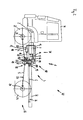
- vehicle drive 1 comprises an internal combustion engine 2 for providing a drive power, a drive train 3 for transmitting the drive power to a plurality of output devices 4, 5 and 6, a driving gear 7 for selecting drive ratios and a transfer case 8 for distributing the drive power to the output device 4, 5 and 6th
- the transfer case 8 is arranged drivable in the present drive train 3 by means of a drive output shaft element 9 of the drive transmission 7.
- a hydraulic drive device 10 which in particular by a hydraulic pump 11, a hydraulic motor 12 and a hydraulic line 13 connecting them comprises.
- the hydraulic pump 11 is arranged drivable in the drive train via a further drive output shaft element 14.
- the entire hydraulic drive device 10 via the drive gear 7 by means of the existing internal combustion engine 2 can be driven.
- the drive power provided by the hydraulic drive device 10 is transmitted to the transfer case 8 by means of a hydraulic motor output shaft member 15.
- Such switchability of the two drive shaft inputs 16 and 17, however, can also be achieved by means of further coupling devices 17A (here only explicitly numbered) acting between the drive gear 7 and the transfer case 8 or the hydraulic drive device 10 and / or the hydraulic drive device 10 and the transfer case 8 are arranged.
- a planetary gear 18 for additionally reducing a hydraulic motor speed is additionally arranged on the second drive shaft input 17.
- the two drive shaft inputs 16 and 17 are structurally advantageously arranged on a common drive shaft input side 19.
- an ideally standardized transfer case 8 can be used.
- the first output device 4 is a cardan shaft 20 for driving the front wheel axle 21 or the front wheels 22 (numbered here only by way of example).
- the second output device 5 is correspondingly a rear propeller shaft 23 for driving a rear wheel axle 24 or the rear wheels 25 (here only by way of example) numbered).
- the third output device 6 is a PTO shaft 26 for driving a working device, not shown here.
- an extremely slow travel of the truck 30 shown here can be made possible when the propulsion of the truck 30, as in the according to the illustration FIG. 2 shown further driving mode, by means of the hydraulic drive device 10 is accomplished.
- the present hydraulic drive device 10 represents an extremely effective creeper drive 31 of the vehicle drive 1 of the present truck 30 shown.
- the present transfer case 8 is a standard transfer case of conventional design, so that the modifications to the vehicle drive 1 are essentially limited only to the addition of the hydraulic drive device 10.
- Most transfer cases 8 conventional design usually have standard already on the second, but usually unused drive shaft input 17, so that the integration of the hydraulic drive device 10 in an existing vehicle drive 1 is structurally particularly simple.
- the present vehicle drive 1 is a very inexpensive to provide alternative to known vehicle drives, which are designed for a slow ride of a motor vehicle.
- the truck 30 also comprises a chassis 32 which, in addition to the vehicle drive 1, in particular still carries a chassis 33 on the one hand and a vehicle cabin 34 on the other hand.
- truck 130 is also equipped with a vehicle drive 101 according to the invention, which comprises a Kriechfahrtantrieb 131 based on a hydraulic drive device 110, so that the vehicle drive 101 is almost identical to the vehicle drive 1 from the embodiment of the FIGS. 1 and 2 is constructed.
- the vehicle drive 101 has an internal combustion engine 102, a drive train 103, first, second and third output devices 104, 105 and 106, as well as a drive gear 107 and a transfer case 108.
- the hydraulic drive device 110 is also characterized by a hydraulic pump 111 and a hydraulic motor 112 with a hydraulic motor output shaft element 115 and a hydraulic line 113 connecting them.
- the transfer case 108 differs from the transfer case 8 of the first embodiment in that a first drive shaft input 116 and a second drive shaft input 117 do not exist on a common drive shaft input side 19 (see FIGS. 1 and 2
- the first drive shaft input 116 is arranged on a drive shaft input front side 140 and the second drive shaft input 117 is arranged in the region of an inspection opening for an intermediate shaft on a drive shaft input rear side 141 of the transfer case 108.
- the drive gear 107 is characterized to drive the transfer case 108 again through a first drive output shaft member 109 and another drive output shaft member 114.
- a planetary gear 118 is provided to additionally reduce a hydraulic motor speed of the hydraulic motor 112 at the secondmaschinewelleneingang 117 accordingly, so that the transfer case 108 with respect to the first output device 104 and the second output device 105 can rotate extremely slowly , so that also an extremely slow crawl of the truck 130 is possible.
- the first output device 104 includes a front propeller shaft 120 for driving a front axle 121 and the front wheels 122 respectively.
- the second output device 105 comprises a rear propeller shaft 123 for driving a rear axle 124 and corresponding rear wheels 125.
- the third drive device 106 has a PTO shaft 126 for driving a working device not shown here, which can be driven by the truck 130.
- the output devices 104, 105 and 106 described above are connected downstream correspondingly assigned drive shaft outputs 127, 128 and 129 of the transfer case 108.
- the transfer case 208 can be driven in a previously known manner only via a driving gear 207 by means of an internal combustion engine 202.
- a first drive shaft input 216 is occupied at the transfer case 208.
- a second availablemaschinewelleneingang 217 is closed only by means of a cover 251 a revision opening and thus not in use.
- the vehicle drive 250 comprises a drive output shaft element 209, by means of which it is connected torque-fit with the transfer case 208.
- the transfer case 208 also has three drive shaft outputs 227, 228, and 229 for driving a front propeller shaft 220, a rear propeller shaft 223, and another output device 206 comprising a PTO shaft 226.
Abstract
Description
Die Erfindung betrifft einerseits einen Fahrzeugantrieb mit einer Brennkraftmaschine zum Bereitstellen einer Antriebsleistung, mit einem Antriebsstrang zum Übertragen der Antriebsleistung an mehrere Abtriebseinrichtungen, mit einem Fahrgetriebe zum Wählen von Antriebsübersetzungen und mit wenigstens einem Verteilergetriebe zum Verteilen der Antriebsleistung an die Abtriebseinrichtungen, bei welchem das wenigstens eine Verteilergetriebe mittels eines Abtriebswellenelements des Fahrzeuggetriebes treibbar in dem Antriebsstrang angeordnet ist.The invention relates on the one hand to a vehicle drive with an internal combustion engine for providing a drive power, with a drive train for transmitting the drive power to a plurality of output devices, with a drive gear for selecting drive ratios and with at least one transfer case for distributing the drive power to the output devices, wherein the at least one Transfer case is arranged drivable by means of an output shaft member of the vehicle transmission in the drive train.
Andererseits betrifft die Erfindung ein Verteilergetriebe mit einem Treibwelleneingang zum Treiben des Verteilergetriebes mittels einer Antriebsvorrichtung eines Fahrzeugantriebs und mit wenigstens einem Treibwellenausgang zum Treiben wenigstens einer Abtriebseinrichtung.On the other hand, the invention relates to a transfer case with a drive shaft input for driving the transfer case by means of a drive device of a vehicle drive and with at least one drive shaft output for driving at least one output device.
Auch betrifft die Erfindung ein schienenungebundenes Fahrzeug mit einem Fahrzeugantrieb oder ein schienengebundenes Fahrzeug mit einem Fahrzeugantrieb.The invention also relates to a rail vehicle with a vehicle drive or a rail-bound vehicle with a vehicle drive.
Des Weiteren betrifft die Erfindung ein Verfahren zum Betreiben eines eine Brennkraftmaschine aufweisenden Fahrzeugs, bei welchem eine durch die Brennkraftmaschine bereitgestellte Antriebsleistung mittels eines Verteilergetriebes an verschiedene Abtriebseinrichtungen verteilt wird und bei welchen mittels der Brennkraftmaschine sowohl das Fahrzeug selbst als auch ein dem Fahrzeug zugeordnetes Arbeitsgerät angetrieben werden kann.Furthermore, the invention relates to a method for operating a vehicle having an internal combustion engine, in which a drive power provided by the internal combustion engine is distributed by means of a transfer case to various output devices and wherein both the vehicle itself and a work implement associated with the vehicle are driven by the internal combustion engine can.
Gattungsgemäße Fahrzeugantriebe sind aus dem Stand der Technik gut bekannt und werden speziell bei Lastkraftfahrzeugen bzw. Nutzkraftfahrzeugen eingesetzt, wobei mittels wenigstens einem Verteilergetriebe die zur Verfügung stehende Antriebsleistung auf unterschiedliche Abtriebseinrichtungen verteilt werden kann. Beispielsweise wird dieses Verteilergetriebe neben dem eigentlichen Fahrgetriebe des Kraftfahrzeugs auch für eine sogenannte Kriechfahrt des Kraftfahrzeugs eingesetzt, welche hauptsächlich dafür vorgesehen ist, dass das Kraftfahrzeug möglichst langsam vorwärts oder seltener rückwärts bewegt werden kann. Beispielsweise kann dies der Fall sein, wenn ein Arbeitsgerät mittels des Kraftfahrzeugs bewegt wird, bei welchem eine möglichst langsame Fortbewegung erforderlich ist.Generic vehicle drives are well known from the prior art and are used especially in trucks or commercial vehicles, wherein the available drive power can be distributed to different output devices by means of at least one transfer case. For example, this transfer case is used in addition to the actual driving gear of the motor vehicle for a so-called crawl of the motor vehicle, which is mainly intended that the vehicle can be moved as slowly forward or less often backwards. For example, this may be the case when a working device is moved by means of the motor vehicle, in which the slowest possible locomotion is required.
Es ist Aufgabe vorliegender Erfindung, gattungsgemäße Fahrzeugantriebe derart weiterzuentwickeln, dass ein besonders langsames Fahren bzw. Vorwärtsbewegen eines Kraftfahrzeugs problemlos möglich ist.It is an object of the present invention to develop generic vehicle drives such that a particularly slow driving or forward movement of a motor vehicle is easily possible.
Die Aufgabe der Erfindung wird einerseits von einem Fahrzeugantrieb mit einer Brennkraftmaschine zum Bereitstellen einer Antriebsleistung, mit einem Antriebsstrang zum Übertragen der Antriebsleistung an mehrere Abtriebseinrichtungen, mit einem Fahrgetriebe zum Wählen von Antriebsübersetzungen und mit wenigstens einem Verteilergetriebe zum Verteilen der Antriebsleistung an die Abtriebseinrichtungen gelöst, bei welchem das wenigstens eine Verteilergetriebe mittels eines Abtriebswellenelements des Fahrgetriebes treibbar in dem Antriebsstrang angeordnet ist, wobei der Fahrzeugantrieb zum kumulativen oder alternativen Treiben des wenigstens einen Verteilergetriebes eine weitere Antriebsvorrichtung umfasst.The object of the invention is achieved on the one hand by a vehicle drive with an internal combustion engine for providing drive power, with a drive train for transmitting the drive power to a plurality of output devices, with a drive gear for selecting drive ratios and with at least one transfer case for distributing the drive power to the output devices in which the at least one transfer case is drivably disposed in the drive train by means of an output shaft element of the drive transmission, wherein the vehicle drive for cumulative or alternative driving of the at least one transfer case comprises a further drive device.
Erfindungsgemäß kann das Verteilergetriebe zumindest teilweise mittels der weiteren Antriebsvorrichtung kumulativ oder alternativ angetrieben werden, sodass zumindest eine eingangsseitige Eingangswelle bzw. vorzugsweise mindestens zwei ausgangsseitige Ausgangswelle des Verteilergetriebes mit einer besonders geringen Drehzahl, jedoch trotzdem sehr drehmomentstark angetrieben werden können.According to the invention, the transfer case can be driven cumulatively or alternatively at least partially by means of the further drive device, so that at least one input-side input shaft or preferably at least two output-side output shaft of the transfer case can be driven with a particularly low rotational speed, but nevertheless with high torque.
Der Begriff "Fahrzeugantrieb" beschreibt im Sinne der Erfindung im Wesentlichen einen eine Brennkraftmaschine umfassenden Antriebsstrang eines Kraftfahrzeugs. Anstelle der Brennkraftmaschine könnte gegebenenfalls als Antriebsvorrichtung bzw. Hauptantriebsmotor auch ein Elektromotor zum Einsatz kommen.The term "vehicle drive" in the context of the invention essentially describes a drive train of a motor vehicle comprising an internal combustion engine. Instead of the internal combustion engine Optionally, an electric motor could also be used as drive device or main drive motor.
Im Gegensatz hierzu stellt die weitere Antriebsvorrichtung lediglich einen Nebenantriebsmotor hinsichtlich des Fahrzeugantriebs dar, mittels welcher das Verteilergetriebe zumindest bereichsweise angetrieben werden kann.In contrast, the further drive device is only a secondary drive motor with respect to the vehicle drive, by means of which the transfer case can be driven at least partially.
Der Begriff "Antriebsstrang" erfasst im Sinne der Erfindung wiederum erforderliche Komponenten, wie Wellenelemente, zum Übertragen einer von der Brennkraftmaschine bereitgestellten Antriebsleistung bis an die jeweilige Abtriebseinrichtung.The term "drive train" in the sense of the invention, in turn, includes required components, such as shaft elements, for transmitting a drive power provided by the internal combustion engine to the respective output device.
In den Antriebsstrang ist insbesondere ein Fahrgetriebe integriert, wobei der Begriff "Fahrgetriebe" im Sinne der Erfindung das Hauptgetriebe zum Auswählen eines Ganges des Kraftfahrzeugs. Beispielsweise ist das Fahrgetriebe als manuelles Schaltgetriebe ausgestaltet.In the drive train in particular a drive gear is integrated, wherein the term "driving gear" in the context of the invention, the main gearbox for selecting a gear of the motor vehicle. For example, the drive gear is designed as a manual transmission.
Insofern unterscheidet sich das vorliegende Fahrgetriebe von anderen Nebengetrieben des Fahrzeugantriebs, wie beispielsweise auch dem hier immer vorhandenen Verteilergetriebe, wobei das Verteilergetriebe vorliegend einerseits wenigstens zwei Eingangswellen und andererseits vorzugsweise wenigstens zwei Ausgangswellen aufweist und es darüber hinaus eine an einer der beiden Eingangswellen bereitgestellte Antriebsleistung auf die wenigstens zwei Ausgangswellen verteilen kann.In this respect, the present drive transmission differs from other auxiliary transmissions of the vehicle drive, such as the transfer case always present here, the transfer case presently on the one hand at least two input shafts and on the other hand preferably at least two output shafts and it also provided on one of the two input shafts drive power to the can distribute at least two output shafts.
Speziell unter diesem Gesichtspunkt wird die Aufgabe der Erfindung ebenfalls von einem Verteilergetriebe mit einem Treibwelleneingang zum Treiben des Verteilergetriebes mittels einer Antriebsvorrichtung eines Fahrzeugantriebs und mit wenigstens einem Treibwellenausgang zum Treiben wenigstens einer Abtriebseinrichtung gelöst, wobei das Verteilergetriebe zumindest einen weiteren Treibwelleneingang für eine weitere Antriebsvorrichtung aufweist, und wobei die beiden Treibwelleneingänge schaltbar sind.Especially in this regard, the object of the invention is also achieved by a transfer case with a drive shaft input for driving the transfer case by means of a drive device of a vehicle drive and at least one drive shaft output for driving at least one output device, wherein the transfer case has at least one further drive shaft input for a further drive device, and wherein the two Treibwelleneingänge are switchable.
Vorzugsweise handelt es sich bei dem weiteren Treibwelleneingang um eine Zwischenwelle des Verteilergetriebes, welche bisher nicht im Sinne der Erfindung als Eingangswelle zum Realisieren eines Kriechfahrtantriebs genutzt wurde.Preferably, the further drive shaft input is an intermediate shaft of the transfer case, which was previously not used within the meaning of the invention as an input shaft for realizing a creep drive.
Um diese Zwischenwelle konstruktiv besonders einfach als Eingangswelle für einen Kriechfahrtantrieb nutzen zu können, wird sie aufgebohrt und in die Bohrung wird ein Wellenstück eingeschrumpft, sodass eine besonders drehmomentstarke Leistungsübertragung konstruktiv einfach zur Verfügung steht.In order to use this intermediate shaft constructionally particularly easy as an input shaft for a Kriechfahrtantrieb, it is drilled and in the bore a shaft piece is shrunk, so that a particularly high-torque power transmission is structurally simple available.
Der Begriff "schaltbar" beschreibt im Sinne vorliegender Erfindung die Funktion, dass das Verteilergetriebe entweder über den ersten oder den zweiten Treibwelleneingang angetrieben werden kann.The term "switchable" in the sense of the present invention describes the function that the transfer case can be driven either via the first or the second drive shaft input.
Insofern wird das Verteilergetriebe entweder direkt über ein Abtriebswellenelement des Fahrgetriebes angesteuert oder mittels der weiteren Antriebsvorrichtung.In this respect, the transfer case is either driven directly via an output shaft element of the drive gear or by means of the further drive device.
Eine derartige Schaltbarkeit der beiden Treibwelleneingänge kann jedoch auch mittels weiterer Kupplungseinrichtungen erzielt werden, die zwischen dem Fahrgetriebe und dem Verteilergetriebe bzw. der weiteren Antriebsvorrichtung und/oder der weiteren Antriebsvorrichtung und dem Verteilergetriebe wirkend angeordnet sind.However, such switchability of the two drive shaft inputs can also be achieved by means of further coupling devices which are arranged to act between the drive gear and the transfer case or the further drive device and / or the further drive device and the transfer case.
Hierdurch ist eine vorteilhafte Sicherungseinrichtung in dem Fahrzeugantrieb integriert, um kritische Antriebssituationen insbesondere an dem Verteilergetriebe zu vermeiden, beispielsweise dass beide Treibwelleneingänge aktiv angesprochen und aktiviert sind.As a result, an advantageous safety device is integrated in the vehicle drive in order to avoid critical drive situations, in particular at the transfer case, for example, that both drive shaft inputs are actively addressed and activated.
Insofern ist eine derartige Schaltbarkeit der beiden Treibwelleneingänge besonders vorteilhaft.In this respect, such switchability of the two drive shaft inputs is particularly advantageous.
Erscheint es vorteilhaft, könnten bei entsprechend konstruierten Verteilergetrieben erste Verteilergetriebewelle über den ersten Treibwelleneingang und zweite Verteilergetriebewellen über den zweiten Treibwelleneingang angetrieben werden.If it appears advantageous, first transfer case shaft could be driven via the first drive shaft input and second transfer shaft via the second Treibwelleneingang at appropriately designed transfer cases.
Idealerweise handelt es sich bei der weiteren Antriebsvorrichtung um eine Hydraulikantriebsvorrichtung, da eine solche konstruktiv einfach in herkömmliche Kraftfahrzeuge integriert werden kann. Mittels der Hydraulikantriebsvorrichtung ist vorteilhafter Weise ein stufenloser Fahrantrieb möglich, welcher bis zum Stillstand stufenlos herunter geregelt werden kann.Ideally, the further drive device is a hydraulic drive device, since such a design can be easily integrated into conventional motor vehicles. By means of the hydraulic drive device is advantageously a continuously variable drive possible, which can be controlled stepless down to a standstill.
Besonders vorteilhaft ist somit eine extrem langsame und drehmomentstarke Fahrt eines mit dem vorliegenden Fahrzeugantrieb ausgerüsteten Kraftfahrzeugs möglich.Thus, an extremely slow and high-torque drive of a motor vehicle equipped with the present vehicle drive is possible in a particularly advantageous manner.
Insofern wird die Aufgabe der Erfindung auch von einem schienenungebundenen Fahrzeug mit einem Fahrzeugantrieb oder einem schienengebundenen Fahrzeug mit einem Fahrzeugantrieb gelöst, bei welchen die Fahrzeuge einen Fahrzeugantrieb und/oder ein Verteilergetriebe nach wenigstens einem der hier genannten Merkmale aufweisen.In this respect, the object of the invention is also achieved by a rail vehicle with a vehicle drive or a rail vehicle with a vehicle drive, in which the vehicles have a vehicle drive and / or a transfer case according to at least one of the features mentioned here.
Der Begriff "schienenungebundenes Fahrzeug" bezeichnet im Sinne der Erfindung im Wesentlichen Straßenkraftfahrzeuge, wie beispielsweise Lastkraftfahrzeuge oder Nutzkraftfahrzeuge. Insofern kann ein schienenungebundenes Fahrzeug im Gegensatz zu einem schienengebundenen Fahrzeug eine beliebige Fahrtrichtung einschlagen. Diese können nicht nur auf Straßen sondern auch auf unbefestigten Wegen oder Geländen eingesetzt werden.For the purposes of the invention, the term "rail-bound vehicle" essentially designates road vehicles, such as, for example, lorries or commercial vehicles. In this respect, unlike a rail-bound vehicle, a rail-bound vehicle can strike any direction of travel. These can be used not only on roads but also on unpaved roads or terrain.
Die Aufgabe der Erfindung wird darüber hinaus insbesondere auch dadurch vorteilhaft gelöst, wenn der Fahrzeugantrieb einen die weitere Antriebsvorrichtung aufweisenden Kriechfahrtantrieb umfasst. Wie bereits beschrieben, kann mittels einer insbesondere hydraulisch betriebenen alternativen Antriebsvorrichtung eine extrem langsame Kriechfahrt an einem Fahrzeug bereitgestellt werden, welche jedoch eine trotzdem sehr drehmomentstarke Antriebsleistung gewährleisten kann. Außerdem kann die Hydraulikantriebsvorrichtung konstruktiv einfach an bestehende Fahrzeugantriebe nachgerüstet werden.The object of the invention is also particularly advantageously solved by the vehicle drive comprises a further drive device having Kriechfahrtantrieb. As already described, by means of an especially hydraulically operated alternative drive device, an extremely slow creeping motion can be provided on a vehicle, which, however, can guarantee a very high-torque drive power. In addition, the hydraulic drive device can be easily retrofitted to existing vehicle drives.
Eine bevorzugte Ausführungsvariante der vorliegenden Erfindung sieht vor, dass das wenigstens eine Verteilergetriebe sowohl einem ersten Treibwelleneingang für das Fahrgetriebe als auch einen zweiten Treibwelleneingang für die weitere Antriebsvorrichtung aufweist. Vorzugsweise sind die beiden Treibwelleneingänge schaltbar, sodass vorzugsweise immer nur eine Antriebseinrichtung das Verteilergetriebe antreiben kann. Jeder der Treibwelleneingänge verfügt über eine eigene Eingangswelle.A preferred embodiment of the present invention provides that the at least one transfer case has both a first drive shaft input for the drive gear and a second drive shaft input for the further drive device. Preferably, the two Treibwelleneingänge are switchable, so preferably always only one drive means can drive the transfer case. Each of the drive shaft inputs has its own input shaft.
Es versteht sich, dass hinsichtlich unterschiedlicher Kraftfahrzeuge an speziell geforderte Ansprüche konzipierte Verteilergetriebe hergestellt werden können.It is understood that with regard to different motor vehicles to specially demanded claims designed transfer case can be produced.
Vorteilhafter Weise können vorliegend jedoch auch herkömmliche Verteilergetriebe verwendet werden, da sie fabrikseitig oftmals neben einem Hauptantriebswelleneingang hinsichtlich des Fahrgetriebes noch über eine Revisionsöffnung mit Zugriff auf eine Zwischenwelle verfügen, der bislang jedoch unbenutzt und nun vorteilhafter Weise als Nebenwellenantriebseingang nutzbar ist.Advantageously, in the present case, however, conventional transfer cases can be used, since they often have factory side next to a main drive shaft input with respect to the drive gear still on a revision opening with access to an intermediate shaft, which has been used but unused and now advantageously as Nebenwellenantriebseingang.
Somit wird die Aufgabe der Erfindung auch von einem Verfahren zum Betreiben eines eine Brennkraftmaschine aufweisenden Fahrzeugs gelöst, bei welchem eine durch die Brennkraftmaschine bereitgestellte Antriebsleistung mittels eines Verteilergetriebes an verschiedene Abtriebseinrichtungen verteilt wird und bei welchen mittels der Brennkraftmaschine sowohl das Fahrzeug als auch ein dem Fahrzeug zugeordnetes Arbeitsgerät angetrieben werden kann, wobei sich das Verfahren dadurch auszeichnet, dass eine Eingangswelle eines ersten Treibwelleneingangs des Verteilergetriebes mittels eines Abtriebswellenelements eines Fahrgetriebes und eine Eingangswelle eines weiteren Treibwelleneingangs des Verteilergetriebes mittels eines Abtriebswellenelements einer weiteren Antriebsvorrichtung angetrieben werden.Thus, the object of the invention is also achieved by a method for operating a vehicle having an internal combustion engine, in which a drive power provided by the internal combustion engine is distributed by means of a transfer case to various output devices and in which by means of the internal combustion engine, both the vehicle and a vehicle associated Implement can be driven, wherein the method is characterized in that an input shaft of a first drive shaft input of the transfer case by means of an output shaft member of a transfer case and an input shaft of a further drive shaft input of the transfer case by means of an output shaft member of another drive device are driven.
Mittels des vorliegenden Verfahrens kann ein Verteilergetriebe eines Fahrzeugs vielfältiger und damit auch vorteilhafter betrieben werden.By means of the present method, a transfer case of a vehicle can be operated more varied and thus also more advantageously.
Darüber hinaus ist es baulich besonders vorteilhaft, wenn die beiden Treibwelleneingänge an einer gemeinsamen Treibwelleneingangsseite angeordnet sind. Durch einen derartigen konstruktiven Aufbau, kann der vorliegende Fahrzeugantrieb besonders kompakt gebaut werden.In addition, it is structurally particularly advantageous if the two Treibwelleneingänge are arranged on a common drive shaft input side. By such a structural design, the present vehicle drive can be built very compact.
Je nach Kundenanforderung kann eine der beiden Treibwelleneingänge des Verteilergetriebes jedoch auch gegenüberliegend an verschiedenen Seiten des Verteilergetriebes vorteilhaft angeordnet sein.Depending on the customer requirement, however, one of the two drive shaft inputs of the transfer case can also be arranged advantageously opposite to different sides of the transfer case.
Eine besonders bevorzugte Ausführungsvariante sieht vor, dass die weitere Antriebsvorrichtung wenigstens einen Hydraulikmotor und/oder wenigstens eine Hydraulikpumpe umfasst. Beispielsweise wird eine Hydraulikpumpe hierbei unmittelbar von einer Abtriebswelle des Fahrgetriebes angetrieben. Die Hydraulikpumpe kann hierbei über eine entsprechende Hydraulikleitung einen verteilergetriebeseitig angeordneten Hydraulikmotor antreiben, welcher dann letztendlich eine der Eingangswellen des Verteilergetriebes antreibt. Hierdurch können vorteilhafter Weise konstruktiv auch größere und für starre Antriebsstrangwellen ungünstig verlaufene Übertragungswege zwischen einem Antriebsmotor und dem Verteilergetriebe überbrückt werden.A particularly preferred embodiment provides that the further drive device comprises at least one hydraulic motor and / or at least one hydraulic pump. For example, a hydraulic pump is in this case driven directly by an output shaft of the drive gear. The hydraulic pump can in this case via a corresponding hydraulic line driving a distributor gear side arranged hydraulic motor, which then ultimately drives one of the input shafts of the transfer case. As a result, advantageously also larger and unfavorable for rigid driveline shafts transmission paths between a drive motor and the transfer case can be bridged.
Insofern ist es konstruktiv zudem vorteilhaft, wenn die weitere Antriebsvorrichtung zwischen dem Fahrgetriebe und dem wenigstens einem Verteilergetriebe wirkend angeordnet ist.In this respect, it is also constructive advantageous if the further drive device between the drive gear and the at least one transfer case is arranged to act.
Es versteht sich, dass insbesondere die Hydraulikantriebsvorrichtung lediglich mit einem Hydraulikmotor ausgerüstet sein kann. Bedarfsweise kann die Hydraulikantriebsvorrichtung jedoch auch mehr als zwei Hydraulikmotoren umfassen.It is understood that in particular the hydraulic drive device can be equipped only with a hydraulic motor. If desired, however, the hydraulic drive device may also comprise more than two hydraulic motors.
Dies kann beispielsweise der Fall sein, wenn der Fahrzeugantrieb mehr als ein Verteilergetriebe aufweist, welche zumindest teilweise mittels einer Hydraulikantriebsvorrichtung bzw. mittels Hydraulikmotoren hiervon angetrieben werden sollen.This can be the case, for example, if the vehicle drive has more than one transfer case, which are to be driven at least partially by means of a hydraulic drive device or by means of hydraulic motors thereof.
Die weitere Antriebsvorrichtung kann konstruktiv besonders einfach angetrieben werden, wenn die weitere Antriebsvorrichtung mittels der Brennkraftmaschine antreibbar in dem Antriebsstrang angeordnet ist.The further drive device can be driven in a structurally particularly simple manner if the further drive device is drivably arranged in the drive train by means of the internal combustion engine.
In diesem Zusammenhang sieht eine bevorzugte Verfahrensvariante vor, dass die weitere Antriebsvorrichtung von der Brennkraftmaschine angetrieben wird.In this context, a preferred variant of the method provides that the further drive device is driven by the internal combustion engine.
Ist darüber hinaus zwischen der weitere Antriebsvorrichtung und dem wenigstens einen Verteilergetriebe ein Planetengetriebe zum Reduzieren einer Motordrehzahl angeordnet, kann die Drehzahl beispielsweise eines relativ hoch drehenden Ölmotors konstruktiv sehr einfach auf eine für das Verteilergetriebe vorteilhafte Antriebsdrehzahl reduziert werden.If, in addition, a planetary gear for reducing an engine speed is arranged between the further drive device and the at least one transfer case, the rotational speed of, for example, a relatively high-revving oil engine can be reduced very simply to a drive rotational speed which is advantageous for the transfer case.
Darüber hinaus ist es vorteilhaft, wenn eine Antriebseinrichtung eine Zapfwelle zum Antreiben eines Arbeitsgerätes oder dergleichen umfasst.Moreover, it is advantageous if a drive device comprises a PTO shaft for driving a working device or the like.
Ebenso ist es vorteilhaft, wenn eine Abtriebseinrichtung eine Kardanwelle umfasst.It is likewise advantageous if an output device comprises a propeller shaft.
Damit Abtriebseinrichtungen des vorliegenden Fahrantriebs problemlos wahlweise über eine ausgangsseitige Fahrgetriebeabtriebswelle oder von der weitere Antriebsvorrichtung angetrieben werden können, ist es vorteilhaft, wenn eine erste dem Verteilergetriebe nachgeordnete Abtriebseinrichtung wenigstens eine zweite dem Verteilergetriebe nachgeordnete Abtriebseinrichtung voneinander entkoppelbar sind.In order that output devices of the present traction drive can be driven either via an output-side drive output shaft or by the further drive device, it is advantageous if a first output device downstream of the transfer case at least one second output device downstream of the transfer case can be decoupled from each other.
Vorteilhafter Weise ist es vorliegend möglich, dass eine besonders langsame Kriechfahrt mittels der Hydraulikantriebsvorrichtung über die zweite Eingangswelle bzw. die Zwischenwelle des Verteilergetriebes bewerkstelligt wird, während der Betrieb der Zapfwelle mittels vollem Drehmoment der Brennkraftmaschine über die erste Eingangswelle des Verteilergetriebes sichergestellt ist. Hierzu muss lediglich das Verteilerwelle derart eingestellt werden, dass die Antriebsleistung der Brennkraftmaschine direkt auf die Abtriebseinrichtung mit der Zapfwelle durchgeschaltet ist und die Antriebsleistung der Hydraulikantriebsvorrichtung auf die Abtriebseinrichtungen mit den Kardanwellen des Fahrantriebs geleitet wird.Advantageously, it is presently possible that a particularly slow creeping is accomplished by means of the hydraulic drive device via the second input shaft or the intermediate shaft of the transfer case, while the operation of the PTO is ensured by full torque of the internal combustion engine via the first input shaft of the transfer case. For this purpose, only the distributor shaft must be adjusted such that the drive power of the internal combustion engine is switched directly to the output device with the PTO and the drive power of the hydraulic drive device is passed to the output devices with the cardan shafts of the traction drive.
Weitere Vorteile, Ziele und Eigenschaften der Erfindung werden anhand der anliegenden Zeichnung und nachfolgender Beschreibung erläutert, in welchen beispielhaft Fahrzeugantriebe mit einer Brennkraftmaschine und erfindungsgemäß mit einer weiteren Antriebsvorrichtung in Gestalt einer Hydraulikantriebsvorrichtung zum Treiben von in Lastkraftwagen verbauten Verteilergetrieben dargestellt und beschrieben sind.Further advantages, objects and features of the invention will be explained with reference to the accompanying drawings and the following description, in which exemplary vehicle drives are shown and described with an internal combustion engine and according to the invention with a further drive device in the form of a hydraulic drive device for driving built-in trucks transfer cases.
In der Zeichnung zeigen:
- Fig. 1
- schematisch eine Seitenansicht eines LKW umfassend ein Fahrzeugantrieb mit einer Brennkraftmaschine und mit einem von einer Hydraulikantriebsvorrichtung zusätzlich treibbaren Verteilergetriebe in einen ersten Fahrmodus ohne Zuhilfenahme eines Hydraulikmotors der Hydraulikantriebsvorrichtung zum Treiben des Verteilergetriebes;
- Fig. 2
- schematisch eine weitere Seitenansicht des LKW aus der
Figur 1 in einem weiteren Fahrmodus unter Zuhilfenahme der Hydraulikantriebsvorrichtung zum zusätzlichen Treiben des Verteilergetriebes; - Fig. 3
- schematisch eine Seitenansicht eines weiteren LKW umfassend einen Fahrzeugantrieb mit einer Brennkraftmaschine und einer Hydraulikantriebsvorrichtung zum zusätzlichen Treiben eines Verteilergetriebes;
- Fig. 4
- schematisch eine Aufsicht des LKW aus der
Fig. 3 ; und - Fig. 5
- schematisch eine Seitenansicht eines LKW mit einem herkömmlichen Fahrzeugantrieb ohne eine Hydraulikantriebsvorrichtung zum zusätzlichen Treiben eines Verteilergetriebes.
- Fig. 1
- schematically a side view of a truck comprising a vehicle drive with an internal combustion engine and with an additional driven by a hydraulic drive device transfer case in a first driving mode without the aid of a hydraulic motor of the hydraulic drive device for driving the transfer case;
- Fig. 2
- schematically another side view of the truck from the
FIG. 1 in a further driving mode with the aid of the hydraulic drive device for additional driving of the transfer case; - Fig. 3
- schematically a side view of another truck comprising a vehicle drive with an internal combustion engine and a hydraulic drive device for additionally driving a transfer case;
- Fig. 4
- schematically a top view of the truck from the
Fig. 3 ; and - Fig. 5
- schematically a side view of a truck with a conventional vehicle drive without a hydraulic drive device for additionally driving a transfer case.
Der in den
Da es sich in dem vorliegenden ersten Ausführungsbeispiel sowohl bei dem Fahrgetriebe 7 als auch bei dem Verteilergetriebe 8 um herkömmliche Getriebe handelt, wird auf deren Funktionsweise und insbesondere innere Getriebeaufbauten hier nicht weiter eingegangen.Since it is in the present first embodiment in both the
Das Verteilergetriebe 8 ist mittels eines Fahrgetriebeabtriebswellenelements 9 des Fahrgetriebes 7 treibbar in dem vorliegenden Antriebsstrang 3 angeordnet.The
Erfindungsgemäß weist der vorliegende Fahrzeugantrieb 1 zum kumulativen oder alternativen Treiben des Verteilergetriebes 8 eine Hydraulikantriebsvorrichtung 10 auf, die sich insbesondere durch eine Hydraulikpumpe 11, einen Hydraulikmotor 12 und eine diese verbindende Hydraulikleitung 13 umfasst.According to the present vehicle drive 1 for cumulative or alternative driving of the
Hierbei ist die Hydraulikpumpe 11 über ein weiteres Fahrgetriebeabtriebswellenelement 14 antreibbar in dem Antriebsstrang angeordnet.Here, the
Insofern ist die gesamte Hydraulikantriebsvorrichtung 10 über das Fahrgetriebe 7 mittels der vorhandenen Brennkraftmaschine 2 antreibbar.In this respect, the entire
Die durch die Hydraulikantriebsvorrichtung 10 bereitgestellte Antriebsleistung wird mittels eines Hydraulikmotorabtriebswellenelements 15 an das Verteilergetriebe 8 übertragen.The drive power provided by the
Konstruktiv besonders einfach kann dies geschehen, wenn die Antriebsleistung einerseits von dem Fahrgetriebeabtriebswellenelement 9 wie herkömmlich über einen ersten Treibwelleneingang 16 des Verteilergetriebes 8 und andererseits kumulativ oder alternativ über einen zweiten vorhandenen Treibwelleneingang 17 an einer Revisionsöffnung einer Zwischenwelle des Verteilergetriebes 8 übertragen wird.This can be achieved in a particularly simple design when the drive power is transmitted from the drive
Eine derartige Schaltbarkeit der beiden Treibwelleneingänge 16 und 17 kann jedoch auch mittels weiterer Kupplungseinrichtungen 17A (hier nur explizit beziffert) erzielt werden, die zwischen dem Fahrgetriebe 7 und dem Verteilergetriebe 8 bzw. der Hydraulikantriebsvorrichtung 10 und/oder der Hydraulikantriebsvorrichtung 10 und dem Verteilergetriebe 8 wirkend angeordnet sind.Such switchability of the two
Da insbesondere der Hydraulikmotor 12 der Hydraulikantriebsvorrichtung 10 in der Regel mit einer relativ hohen Drehzahl betrieben wird, ist dahinter noch ein Planetengetriebe 18 zum zusätzlichen Reduzieren einer Hydraulikmotordrehzahl am zweiten Treibwelleneingang 17 angeordnet.Since, in particular, the
In diesem ersten Ausführungsbeispiel sind die beiden Treibwelleneingänge 16 und 17 konstruktiv vorteilhaft an einer gemeinsamen Treibwelleneingangsseite 19 angeordnet. Insofern kann vorteilhafter Weise ein idealweise standardisiertes Verteilergetriebe 8 verwendet werden.In this first exemplary embodiment, the two
Die erste Abtriebseinrichtung 4 ist in diesem Ausführungsbeispiel eine Kardanwelle 20 zum Antreiben der Vorderradachse 21 bzw. der Vorderräder 22 (hier nur exemplarisch beziffert). Bei der zweiten Abtriebseinrichtung 5 handelt es sich entsprechend um eine hintere Kardanwelle 23 zum Antreiben einer Hinterradachse 24 bzw. der Hinterräder 25 (hier nur exemplarisch beziffert). Bei der dritten Abtriebseinrichtung 6 handelt es sich um eine Zapfwelle 26 zum Antreiben eines hier nicht gezeigten Arbeitsgerätes.In this exemplary embodiment, the first output device 4 is a
Damit nun das Verteilergetriebe 8 und die dahinter wirkenden Abtriebseinrichtungen 4, 5 und 6 sowohl von dem Fahrgetriebe 7 als auch von der Hydraulikantriebsvorrichtung 10 gleichzeitig aber getrennt voneinander angetrieben werden können, können insbesondere die beiden Treibwelleneingänge 16 und 17 sowie entsprechende Treibwellenausgänge 27, 28 und 29 des Verteilergetriebes 8 mechanisch voneinander entkoppelt werden. Am Treibwellenausgang 29 ist noch eine Kupplung 29A vorgesehen, um die Zapfwelle 26 vom Antrieb zu entkoppeln.So that now the
Vorteilhafter Weise kann mit der Hydraulikantriebsvorrichtung 10 eine extrem langsame Fahrt des hier dargestellten LKW 30 ermöglicht werden, wenn der Vortrieb des LKW 30, wie in dem nach der Darstellung gemäß der
In dem weiteren Fahrmodus (siehe
Insofern stellt die vorliegende Hydraulikantriebsvorrichtung 10 einen extrem effektiven Kriechfahrtantrieb 31 des Fahrzeugantriebs 1 des vorliegenden gezeigten LKW 30 dar.In this respect, the present
Hingegen wird in dem herkömmlichen Fahrmodus (siehe
Vorteilhafterweise handelt es sich bei dem vorliegenden Verteilergetriebe 8 um ein Standardverteilergetriebe herkömmlicher Bauart, sodass sich die Modifikationen an dem Fahrzeugantrieb 1 im Wesentlichen lediglich auf das Hinzufügen der Hydraulikantriebsvorrichtung 10 beschränkt. Die meisten Verteilergetriebe 8 herkömmlicher Bauart verfügen üblicherweise standardmäßig bereits über den zweiten, meist jedoch ungenutzten Treibwelleneingang 17, sodass die Integration der Hydraulikantriebsvorrichtung 10 in einen bestehenden Fahrzeugantrieb 1 konstruktiv besonders einfach möglich ist.Advantageously, the
Gleiches gilt hinsichtlich des Fahrgetriebes 7 in Bezug auf das weitere Fahrgetriebeabtriebswellenelement 14 zum Treiben des ersten Hydraulikmotors 11 der Hydraulikantriebsvorrichtung 10.The same applies with regard to the
Insofern stellt der vorliegende Fahrzeugantrieb 1 eine sehr kostengünstig bereitstellbare Alternative zu bekannten Fahrzeugantrieben dar, welche für eine langsame Fahrt eines Kraftfahrzeugs ausgelegt sind.In this respect, the present vehicle drive 1 is a very inexpensive to provide alternative to known vehicle drives, which are designed for a slow ride of a motor vehicle.
Der LKW 30 umfasst hierbei noch ein Chassis 32, welches neben dem Fahrzeugantrieb 1 insbesondere einerseits noch ein Fahrwerk 33 und andererseits noch eine Fahrzeugkabine 34 trägt.In this case, the
Der in den
Insofern weist der Fahrzeugantrieb 101 eine Brennkraftmaschine 102, einen Antriebsstrang 103, erste, zweite und dritte Abtriebseinrichtungen 104, 105 und 106 auf sowie ein Fahrgetriebe 107 und ein Verteilergetriebe 108.In this respect, the
Die Hydraulikantriebsvorrichtung 110 zeichnet sich ebenfalls durch eine Hydraulikpumpe 111 und einen Hydraulikmotor 112 mit einem Hydraulikmotorabtriebswellenelement 115 sowie eine diese verbindende Hydraulikleitung 113 aus.The hydraulic drive device 110 is also characterized by a
Das Verteilergetriebe 108 unterscheidet sich von dem Verteilergetriebe 8 aus dem ersten Ausführungsbeispiel jedoch dadurch, dass ein erster Treibwelleneingang 116 und ein zweiter Treibwelleneingang 117 nicht an einer gemeinsamen Treibwelleneingangsseite 19 (siehe
Das Fahrgetriebe 107 zeichnet sich zum Treiben des Verteilergetriebes 108 wieder durch ein erstes Fahrgetriebeabtriebswellenelement 109 und ein weiteres Fahrgetriebeabtriebswellenelement 114 aus.The
Ansonsten ist zwischen dem Hydraulikmotor 112 und dem zweiten Treibwelleneingang 117 ein Planetengetriebe 118 vorgesehen, um eine Hydraulikmotordrehzahl des Hydraulikmotors 112 am zweiten Treibwelleneingang 117 zusätzlich entsprechend reduzieren zu können, sodass das Verteilergetriebe 108 hinsichtlich der ersten Abtriebseinrichtung 104 und der zweiten Abtriebseinrichtung 105 extrem langsam drehen kann, sodass hierdurch auch eine extrem langsame Kriechfahrt des LKW 130 möglich ist.Otherwise, between the
Des Weiteren umfasst die erste Abtriebseinrichtung 104 eine vordere Kardanwelle 120 zum Antreiben einer Vorderachse 121 bzw. der Vorderräder 122. Entsprechend umfasst die zweite Abtriebseinrichtung 105 eine hintere Kardanwelle 123 zum Antreiben einer Hinterachse 124 sowie von entsprechenden Hinterrädern 125. Die dritte Antriebseinrichtung 106 weist eine Zapfwelle 126 zum Antreiben eines hier nicht weiter dargestellten Arbeitsgerätes auf, welches von dem LKW 130 angetrieben werden kann.Furthermore, the
Die zuvor beschriebenen Abtriebseinrichtungen 104, 105 und 106 sind entsprechend zugeordneten Treibwellenausgängen 127, 128 und 129 des Verteilergetriebes 108 nachgeschaltet.The
Zum Vergleich gegenüber der erfindungsgemäßen Fahrzeugantriebe 1 und 101 ist in der Darstellung gemäß der
Zwar ist mit dem herkömmlichen Fahrzeugantrieb 250 ebenfalls eine Kriechfahrt des LKW 230 möglich, jedoch nicht so extrem langsam und drehmomentstark wie es mit den beiden zuvor beschriebenen erfindungsgemäßen Fahrzeugantrieben 1 bzw. 101 der Fall ist.Although it is also possible with the conventional vehicle drive 250 crawl of the
Es versteht sich, dass es sich bei den vorstehend erläuterten Ausführungsbeispielen lediglich um erste Ausgestaltungen des erfindungsgemäßen Fahrzeugantriebs handelt. Insofern beschränkt sich die Ausgestaltung der Erfindung nicht auf diese Ausführungsbeispiele.It goes without saying that the exemplary embodiments explained above are only first embodiments of the vehicle drive according to the invention. In this respect, the embodiment of the invention is not limited to these embodiments.
Sämtliche in den Anmeldungsunterlagen offenbarten Merkmale werden als erfindungswesentlich beansprucht, sofern sie einzeln oder in Kombination gegenüber dem Stand der Technik neu sind.All disclosed in the application documents features are claimed as essential to the invention, provided they are new individually or in combination over the prior art.
- 11
- Fahrzeugantriebvehicle drive
- 22
- BrennkraftmaschinenInternal combustion engines
- 33
- Antriebsstrangpowertrain
- 44
- erste Abtriebseinrichtungfirst output device
- 55
- zweite Abtriebseinrichtungsecond output device
- 66
- dritte Abtriebseinrichtungthird output device
- 77
- FahrgetriebeTravel gear
- 88th
- VerteilergetriebeTransfer Case
- 99
- FahrgetriebeabtriebswellenelementDrive transmission output shaft member
- 1010
- HydraulikantriebsvorrichtungHydraulic drive device
- 1111
- Hydraulikpumpehydraulic pump
- 1212
- Hydraulikmotorhydraulic motor
- 1313
- Hydraulikleitunghydraulic line
- 1414
- weiteres Fahrgetriebeabtriebswellenelementanother drive output shaft element
- 1515
- HydraulikmotorabtriebswellenelementHydraulic motor output shaft member
- 1616
- erster Treibwelleneingangfirst drive shaft input
- 1717
- zweiter Treibwelleneingangsecond drive shaft input
- 17A17A
- Kupplungseinrichtungcoupling device
- 1818
- Planetengetriebeplanetary gear
- 1919
- gemeinsame Treibwelleneingangsseitecommon drive shaft input side
- 2020
- vordere Kardanwellefront propshaft
- 2121
- Vorderradachsefront axle
- 2222
- Vorderräderfront wheels
- 2323
- hintere Kardanwellerear propshaft
- 2424
- Hinterachserear axle
- 2525
- Hinterräderrear wheels
- 2626
- ZapfwellePTO
- 2727
- erster Treibwellenausgangfirst drive shaft output
- 2828
- zweiter Treibwellenausgangsecond drive shaft output
- 2929
- dritter Treibwellenausgangthird drive shaft output
- 29A29A
- Kupplungclutch
- 3030
- LKWtruck
- 3131
- KriechfahrtantriebKriechfahrtantrieb
- 3232
- Chassischassis
- 3333
- Fahrwerklanding gear
- 3434
- Fahrzeugkabinecabin
- 101101
- Fahrzeugantriebvehicle drive
- 102102
- BrennkraftmaschinenInternal combustion engines
- 103103
- Antriebsstrangpowertrain
- 104104
- erste Abtriebseinrichtungfirst output device
- 105105
- zweite Abtriebseinrichtungsecond output device
- 106106
- dritte Abtriebseinrichtungthird output device
- 107107
- FahrgetriebeTravel gear
- 108108
- VerteilergetriebeTransfer Case
- 109109
- FahrgetriebeabtriebswellenelementDrive transmission output shaft member
- 110110
- HydraulikantriebsvorrichtungHydraulic drive device
- 111111
- Hydraulikpumpehydraulic pump
- 112112
- Hydraulikmotorhydraulic motor
- 113113
- Hydraulikleitunghydraulic line
- 114114
- weiteres Fahrgetriebeabtriebswellenelementanother drive output shaft element
- 115115
- HydraulikmotorabtriebswellenelementHydraulic motor output shaft member
- 116116
- erster Treibwelleneingangfirst drive shaft input
- 117117
- zweiter Treibwelleneingangsecond drive shaft input
- 118118
- Planetengetriebeplanetary gear
- 120120
- vordere Kardanwellefront propshaft
- 121121
- VorderachseFront
- 122122
- Vorderräderfront wheels
- 123123
- hintere Kardanwellerear propshaft
- 124124
- Hinterachserear axle
- 125125
- Hinterräderrear wheels
- 126126
- ZapfwellePTO
- 127127
- erster Treibwellenausgangfirst drive shaft output
- 128128
- zweiter Treibwellenausgangsecond drive shaft output
- 129129
- dritter Treibwellenausgangthird drive shaft output
- 130130
- LKWtruck
- 131131
- KriechfahrtantriebKriechfahrtantrieb
- 140140
- TreibwelleneingangsvorderseiteDrive shaft entrance front
- 141141
- TreibwelleneingangsrückseiteDrive shaft entrance back
- 201201
- Fahrzeugantriebvehicle drive
- 202202
- BrennkraftmaschineInternal combustion engine
- 206206
- weitere Abtriebseinrichtungfurther output device
- 207207
- FahrgetriebeTravel gear
- 208208
- VerteilergetriebeTransfer Case
- 209209
- FahrgetriebeabtriebswellenelementDrive transmission output shaft member
- 216216
- erster Treibwelleneingangfirst drive shaft input
- 217217
- zweiter Treibwelleneingangsecond drive shaft input
- 220220
- vordere Kardanwellefront propshaft
- 223223
- hintere Kardanwellerear propshaft
- 226226
- ZapfwellePTO
- 227227
- erster Treibwellenausgangfirst drive shaft output
- 228228
- zweiter Treibwellenausgangsecond drive shaft output
- 229229
- dritter Treibwellenausgangthird drive shaft output
- 230230
- LKWtruck
- 250250
- herkömmlicher Fahrzeugantriebconventional vehicle drive
- 251251
- Abdeckungcover
Claims (14)
dadurch gekennzeichnet, dass
der Fahrzeugantrieb (1; 101) zum kumulativen oder alternativen Treiben des wenigstens einen Verteilergetriebes (8; 108) eine weitere Antriebsvorrichtung (10; 110) umfasst.A vehicle drive (1, 101) having an internal combustion engine (2, 102) for providing a drive power, comprising a drive train (3, 103) for transmitting the drive power to a plurality of output devices (4, 5, 6, 104, 105, 106) Driving gear (7; 107) for selecting drive ratios and at least one transfer case (8; 108) for distributing the drive power to the output devices (4, 5, 6; 104, 105, 106), wherein the at least one transfer case (8; 108) is drivably arranged in the drive train (3; 103) by means of an output shaft element (9; 109) of the drive transmission (7; 107),
characterized in that
the vehicle drive (1; 101) comprises a further drive device (10; 110) for the cumulative or alternative driving of the at least one transfer case (8;
dadurch gekennzeichnet, dass
das wenigstens eine Verteilergetriebe (8; 108) sowohl einen ersten Treibwelleneingang (16; 116) für das Fahrgetriebe (7; 107) als auch einen zweiten Treibwelleneingang (17; 117) für die weitere Antriebsvorrichtung (10; 110) aufweist, wobei insbesondere die beiden Treibwelleneingänge (16, 17; 116, 117) schaltbar sind.Vehicle drive (1; 101) according to claim 1,
characterized in that
the at least one transfer case (8; 108) has both a first drive shaft input (16; 116) for the drive gear (7; 107) and a second drive shaft input (17; 117) for the further drive device (10; two Treibwelleneingänge (16, 17, 116, 117) are switchable.
dadurch gekennzeichnet, dass
die beiden Treibwelleneingänge (16, 17) an einer gemeinsamen Treibwelleneingangsseite (19) angeordnet sind.Vehicle drive (1) according to claim 1 or 2,
characterized in that
the two drive shaft inputs (16, 17) are arranged on a common drive shaft input side (19).
dadurch gekennzeichnet, dass
die weitere Antriebsvorrichtung (10; 110) eine Hydraulikantriebsvorrichtung umfasst.Vehicle drive (1; 101) according to one of claims 1 to 3,
characterized in that
the further drive device (10, 110) comprises a hydraulic drive device.
dadurch gekennzeichnet, dass
die weitere Antriebsvorrichtung (10; 110) wenigstens einen Hydraulikmotor (11; 111) und/oder wenigstens eine Hydraulikpumpe (12; 112) umfasst.Vehicle drive (1; 101) according to one of Claims 1 to 4,
characterized in that
the further drive device (10; 110) comprises at least one hydraulic motor (11; 111) and / or at least one hydraulic pump (12; 112).
dadurch gekennzeichnet, dass
der Fahrzeugantrieb (1; 101) einen die weitere Antriebsvorrichtung (10; 110) aufweisenden Kriechfahrtantrieb (31; 131) umfasst.Vehicle drive (1; 101) according to one of claims 1 to 5,
characterized in that
the vehicle drive (1, 101) comprises a crawler drive (31, 131) having the further drive device (10, 110).
dadurch gekennzeichnet, dass
die weitere Antriebsvorrichtung (10; 110) mittels der Brennkraftmaschine (2; 102) antreibbar in dem Antriebsstrang angeordnet ist.Vehicle drive (1; 101) according to one of claims 1 to 6,
characterized in that
the further drive device (10, 110) is drivably arranged in the drive train by means of the internal combustion engine (2, 102).
dadurch gekennzeichnet, dass
die weitere Antriebsvorrichtung (10; 110) zwischen dem Fahrgetriebe (7; 107) und dem wenigstens einen Verteilergetriebe (8; 108) wirkend angeordnet ist.Vehicle drive (1; 101) according to one of Claims 1 to 7,
characterized in that
the further drive device (10, 110) is arranged to act between the drive gear (7, 107) and the at least one transfer case (8, 108).
dadurch gekennzeichnet, dass
zwischen der weiteren Antriebsvorrichtung (10; 110) und dem wenigstens einen Verteilergetriebe (8; 108) ein Planetengetriebe (18; 118) zum Reduzieren einer Hydraulikmotordrehzahl angeordnet ist.Vehicle drive (1; 101) according to one of Claims 1 to 8,
characterized in that
between the further drive device (10; 110) and the at least one transfer case (8; 108) a planetary gear (18; 118) is arranged for reducing a hydraulic motor speed.
dadurch gekennzeichnet, dass
eine erste dem Verteilergetriebe (8; 108) nachgeordnete Abtriebseinrichtung (6) und wenigstens eine zweite dem Verteilergetriebe (8; 108) nachgeordnete Abtriebseinrichtung (4, 5) voneinander entkoppelbar sind.Vehicle drive (1; 101) according to one of Claims 1 to 9,
characterized in that
a first output device (6) arranged downstream of the transfer case (8; and at least one second output device (4, 5) downstream of the transfer case (8, 108) can be decoupled from one another.
einen Fahrzeugantrieb (1; 101) nach einem der Ansprüche 1 bis 10 und/oder ein Verteilergetriebe (8; 108) nach Anspruch 11.A trackless vehicle (30; 130) having a vehicle drive (1; 101) or a rail vehicle having a vehicle drive (1; 101) characterized
A vehicle drive (1; 101) according to any one of claims 1 to 10 and / or a transfer case (8; 108) according to claim 11.
dadurch gekennzeichnet, dass eine Eingangswelle eines ersten Treibwelleneingangs (16; 116) des Verteilergetriebes (8; 108) mittels eines Abtriebswellenelements (9; 109) eines Fahrgetriebes (7; 107) und eine Eingangswelle eines weiteren Treibwelleneingangs (17; 117) des Verteilergetriebes (8; 108) mittels eines Abtriebswellenelements (15; 115) einer weiteren Antriebsvorrichtung (10; 110) angetrieben werden.Method for operating a vehicle (30; 130) having an internal combustion engine (2; 102), in which a drive power provided by the internal combustion engine (2; 102) is transmitted to different output devices (4, 5, 6; 104, 105, 106) and in which by means of the internal combustion engine (2; 102) both the vehicle (30; 130) itself and an implement associated with the vehicle (30; 130) can be driven,
characterized in that an input shaft of a first drive shaft input (16; 116) of the transfer case (8; 108) by means of an output shaft member (9; 109) of a drive gear (7; 107) and an input shaft of a further drive shaft input (17; 117) of the transfer case (7; 8, 108) are driven by means of an output shaft element (15, 115) of a further drive device (10, 110).
dadurch gekennzeichnet, dass
die Eingangswelle des weiteren Treibwelleneingangs (17; 117) von einer Hydraulikantriebsvorrichtung (10; 110) angetrieben wird.Method according to claim 13,
characterized in that
the input shaft of the further drive shaft input (17; 117) is driven by a hydraulic drive device (10; 110).
Priority Applications (1)
| Application Number | Priority Date | Filing Date | Title |
|---|---|---|---|
| EP20110008185 EP2581255B1 (en) | 2011-10-10 | 2011-10-10 | Vehicle drive with a combustion engine, distributor gear, rail vehicle or non-rail vehicle and method for operating a vehicle comprising a combustion engine |
Applications Claiming Priority (1)
| Application Number | Priority Date | Filing Date | Title |
|---|---|---|---|
| EP20110008185 EP2581255B1 (en) | 2011-10-10 | 2011-10-10 | Vehicle drive with a combustion engine, distributor gear, rail vehicle or non-rail vehicle and method for operating a vehicle comprising a combustion engine |
Publications (2)
| Publication Number | Publication Date |
|---|---|
| EP2581255A1 true EP2581255A1 (en) | 2013-04-17 |
| EP2581255B1 EP2581255B1 (en) | 2015-04-29 |
Family
ID=45715005
Family Applications (1)
| Application Number | Title | Priority Date | Filing Date |
|---|---|---|---|
| EP20110008185 Active EP2581255B1 (en) | 2011-10-10 | 2011-10-10 | Vehicle drive with a combustion engine, distributor gear, rail vehicle or non-rail vehicle and method for operating a vehicle comprising a combustion engine |
Country Status (1)
| Country | Link |
|---|---|
| EP (1) | EP2581255B1 (en) |
Cited By (2)
| Publication number | Priority date | Publication date | Assignee | Title |
|---|---|---|---|---|
| DE102016006208A1 (en) * | 2016-05-19 | 2017-11-23 | Man Truck & Bus Ag | Battery-electric commercial vehicle, in particular lorries |
| EP3835101A1 (en) * | 2019-12-10 | 2021-06-16 | Oliver Merkt | Vehicle drive for simultaneous driving of a vehicle and a working device |
Citations (3)
| Publication number | Priority date | Publication date | Assignee | Title |
|---|---|---|---|---|
| GB2304835A (en) * | 1995-09-07 | 1997-03-26 | Rover Group | Control of gearshifting in an automatic transmission in series with a manual range gearbox |
| US20040220007A1 (en) * | 2003-05-02 | 2004-11-04 | Christoph Pelchen | Distributor transmission having at least three shafts |
| US20110079454A1 (en) * | 2009-10-07 | 2011-04-07 | Gm Global Technology Operations, Inc. | Hybrid vehicle configuration and method of reconfiguring non-hybrid vehicle architecture as hybrid vehicle architecture |
-
2011
- 2011-10-10 EP EP20110008185 patent/EP2581255B1/en active Active
Patent Citations (3)
| Publication number | Priority date | Publication date | Assignee | Title |
|---|---|---|---|---|
| GB2304835A (en) * | 1995-09-07 | 1997-03-26 | Rover Group | Control of gearshifting in an automatic transmission in series with a manual range gearbox |
| US20040220007A1 (en) * | 2003-05-02 | 2004-11-04 | Christoph Pelchen | Distributor transmission having at least three shafts |
| US20110079454A1 (en) * | 2009-10-07 | 2011-04-07 | Gm Global Technology Operations, Inc. | Hybrid vehicle configuration and method of reconfiguring non-hybrid vehicle architecture as hybrid vehicle architecture |
Cited By (2)
| Publication number | Priority date | Publication date | Assignee | Title |
|---|---|---|---|---|
| DE102016006208A1 (en) * | 2016-05-19 | 2017-11-23 | Man Truck & Bus Ag | Battery-electric commercial vehicle, in particular lorries |
| EP3835101A1 (en) * | 2019-12-10 | 2021-06-16 | Oliver Merkt | Vehicle drive for simultaneous driving of a vehicle and a working device |
Also Published As
| Publication number | Publication date |
|---|---|
| EP2581255B1 (en) | 2015-04-29 |
Similar Documents
| Publication | Publication Date | Title |
|---|---|---|
| DE102006038358B4 (en) | Final drive unit for a drive train | |
| EP3109509B1 (en) | Gearbox assembly | |
| EP2562442B1 (en) | Gearbox, in particular for a powertrain in motor vehicles, rail vehicles or similar | |
| DE102011003264A1 (en) | Transmission device of a drive train for distributing the drive torque between two drive shafts | |
| EP3246188A1 (en) | Commercial vehicle with a parallel hybrid drive train | |
| DE102020000449A1 (en) | Transmission with power take-off | |
| DE102018206411B4 (en) | Drive train for an electrically operated machine | |
| DE102013222086A1 (en) | Drive train for a rail vehicle | |
| DE102008001614B4 (en) | Drive train of a combine harvester or a forage harvester | |
| EP2581255B1 (en) | Vehicle drive with a combustion engine, distributor gear, rail vehicle or non-rail vehicle and method for operating a vehicle comprising a combustion engine | |
| DE102020004582A1 (en) | Hybrid drive system for a vehicle | |
| DE102020101667A1 (en) | Drive train for a motor vehicle | |
| DE102008044035B4 (en) | A four-wheel hybrid powertrain for a motor vehicle and method of operating the hybrid powertrain | |
| DE10319683A1 (en) | Power split transmission with at least two transmission input shafts | |
| DE102015206160A1 (en) | Powertrain for an agricultural work vehicle | |
| WO2019120803A1 (en) | Electric drive arrangement for work machine | |
| DE102015208756A1 (en) | Transmission device for a hybrid drive system | |
| DE102008052072B4 (en) | Motor vehicle with four-wheel drive | |
| DE102006057836A1 (en) | Commercial vehicle used as a tractor comprises a guiding frame for introducing the drive power into a continuous gear unit and an adapter gear unit so that a maximum specified driving speed is reached | |
| EP3034348B1 (en) | Distributor gear for dividing a torque to at least a first and a second axle shaft of a motor vehicle | |
| DE102020101668A1 (en) | Shift strategy for a transmission | |
| DE102020000462A1 (en) | Modular transmission kit for a motor vehicle | |
| EP2248699B1 (en) | Powertrain for a vehicle comprising an infinitely adjustable gearbox | |
| DE102011086062A1 (en) | Electrified drive assembly for hybrid vehicle, has coupling element formed such that drive unit is uncoupled for transferring torque to or from powertrain, where drive unit is formed as high-speed electromotor and rear drive | |
| DE102007053321A1 (en) | Ground speed PTO |
Legal Events
| Date | Code | Title | Description |
|---|---|---|---|
| PUAI | Public reference made under article 153(3) epc to a published international application that has entered the european phase |
Free format text: ORIGINAL CODE: 0009012 |
|
| AK | Designated contracting states |
Kind code of ref document: A1 Designated state(s): AL AT BE BG CH CY CZ DE DK EE ES FI FR GB GR HR HU IE IS IT LI LT LU LV MC MK MT NL NO PL PT RO RS SE SI SK SM TR |
|
| AX | Request for extension of the european patent |
Extension state: BA ME |
|
| 17P | Request for examination filed |
Effective date: 20130718 |
|
| RBV | Designated contracting states (corrected) |
Designated state(s): AL AT BE BG CH CY CZ DE DK EE ES FI FR GB GR HR HU IE IS IT LI LT LU LV MC MK MT NL NO PL PT RO RS SE SI SK SM TR |
|
| 17Q | First examination report despatched |
Effective date: 20141031 |
|
| GRAP | Despatch of communication of intention to grant a patent |
Free format text: ORIGINAL CODE: EPIDOSNIGR1 |
|
| INTG | Intention to grant announced |
Effective date: 20141219 |
|
| GRAS | Grant fee paid |
Free format text: ORIGINAL CODE: EPIDOSNIGR3 |
|
| GRAA | (expected) grant |
Free format text: ORIGINAL CODE: 0009210 |
|
| AK | Designated contracting states |
Kind code of ref document: B1 Designated state(s): AL AT BE BG CH CY CZ DE DK EE ES FI FR GB GR HR HU IE IS IT LI LT LU LV MC MK MT NL NO PL PT RO RS SE SI SK SM TR |
|
| REG | Reference to a national code |
Ref country code: GB Ref legal event code: FG4D Free format text: NOT ENGLISH |
|
| REG | Reference to a national code |
Ref country code: CH Ref legal event code: EP |
|
| REG | Reference to a national code |
Ref country code: AT Ref legal event code: REF Ref document number: 724227 Country of ref document: AT Kind code of ref document: T Effective date: 20150515 |
|
| REG | Reference to a national code |
Ref country code: IE Ref legal event code: FG4D Free format text: LANGUAGE OF EP DOCUMENT: GERMAN |
|
| REG | Reference to a national code |
Ref country code: DE Ref legal event code: R096 Ref document number: 502011006694 Country of ref document: DE Effective date: 20150603 |
|
| REG | Reference to a national code |
Ref country code: CH Ref legal event code: NV Representative=s name: ROTTMANN, ZIMMERMANN + PARTNER AG, CH |
|
| REG | Reference to a national code |
Ref country code: NL Ref legal event code: T3 |
|
| REG | Reference to a national code |
Ref country code: LT Ref legal event code: MG4D |
|
| PG25 | Lapsed in a contracting state [announced via postgrant information from national office to epo] |
Ref country code: HR Free format text: LAPSE BECAUSE OF FAILURE TO SUBMIT A TRANSLATION OF THE DESCRIPTION OR TO PAY THE FEE WITHIN THE PRESCRIBED TIME-LIMIT Effective date: 20150429 Ref country code: NO Free format text: LAPSE BECAUSE OF FAILURE TO SUBMIT A TRANSLATION OF THE DESCRIPTION OR TO PAY THE FEE WITHIN THE PRESCRIBED TIME-LIMIT Effective date: 20150729 Ref country code: ES Free format text: LAPSE BECAUSE OF FAILURE TO SUBMIT A TRANSLATION OF THE DESCRIPTION OR TO PAY THE FEE WITHIN THE PRESCRIBED TIME-LIMIT Effective date: 20150429 Ref country code: PT Free format text: LAPSE BECAUSE OF FAILURE TO SUBMIT A TRANSLATION OF THE DESCRIPTION OR TO PAY THE FEE WITHIN THE PRESCRIBED TIME-LIMIT Effective date: 20150831 Ref country code: LT Free format text: LAPSE BECAUSE OF FAILURE TO SUBMIT A TRANSLATION OF THE DESCRIPTION OR TO PAY THE FEE WITHIN THE PRESCRIBED TIME-LIMIT Effective date: 20150429 Ref country code: FI Free format text: LAPSE BECAUSE OF FAILURE TO SUBMIT A TRANSLATION OF THE DESCRIPTION OR TO PAY THE FEE WITHIN THE PRESCRIBED TIME-LIMIT Effective date: 20150429 |
|
| PG25 | Lapsed in a contracting state [announced via postgrant information from national office to epo] |
Ref country code: GR Free format text: LAPSE BECAUSE OF FAILURE TO SUBMIT A TRANSLATION OF THE DESCRIPTION OR TO PAY THE FEE WITHIN THE PRESCRIBED TIME-LIMIT Effective date: 20150730 Ref country code: IS Free format text: LAPSE BECAUSE OF FAILURE TO SUBMIT A TRANSLATION OF THE DESCRIPTION OR TO PAY THE FEE WITHIN THE PRESCRIBED TIME-LIMIT Effective date: 20150829 Ref country code: LV Free format text: LAPSE BECAUSE OF FAILURE TO SUBMIT A TRANSLATION OF THE DESCRIPTION OR TO PAY THE FEE WITHIN THE PRESCRIBED TIME-LIMIT Effective date: 20150429 Ref country code: RS Free format text: LAPSE BECAUSE OF FAILURE TO SUBMIT A TRANSLATION OF THE DESCRIPTION OR TO PAY THE FEE WITHIN THE PRESCRIBED TIME-LIMIT Effective date: 20150429 |
|
| PG25 | Lapsed in a contracting state [announced via postgrant information from national office to epo] |
Ref country code: EE Free format text: LAPSE BECAUSE OF FAILURE TO SUBMIT A TRANSLATION OF THE DESCRIPTION OR TO PAY THE FEE WITHIN THE PRESCRIBED TIME-LIMIT Effective date: 20150429 Ref country code: DK Free format text: LAPSE BECAUSE OF FAILURE TO SUBMIT A TRANSLATION OF THE DESCRIPTION OR TO PAY THE FEE WITHIN THE PRESCRIBED TIME-LIMIT Effective date: 20150429 |
|
| REG | Reference to a national code |
Ref country code: DE Ref legal event code: R097 Ref document number: 502011006694 Country of ref document: DE |
|
| PG25 | Lapsed in a contracting state [announced via postgrant information from national office to epo] |
Ref country code: SK Free format text: LAPSE BECAUSE OF FAILURE TO SUBMIT A TRANSLATION OF THE DESCRIPTION OR TO PAY THE FEE WITHIN THE PRESCRIBED TIME-LIMIT Effective date: 20150429 Ref country code: RO Free format text: LAPSE BECAUSE OF NON-PAYMENT OF DUE FEES Effective date: 20150429 Ref country code: PL Free format text: LAPSE BECAUSE OF FAILURE TO SUBMIT A TRANSLATION OF THE DESCRIPTION OR TO PAY THE FEE WITHIN THE PRESCRIBED TIME-LIMIT Effective date: 20150429 Ref country code: CZ Free format text: LAPSE BECAUSE OF FAILURE TO SUBMIT A TRANSLATION OF THE DESCRIPTION OR TO PAY THE FEE WITHIN THE PRESCRIBED TIME-LIMIT Effective date: 20150429 |
|
| PLBE | No opposition filed within time limit |
Free format text: ORIGINAL CODE: 0009261 |
|
| STAA | Information on the status of an ep patent application or granted ep patent |
Free format text: STATUS: NO OPPOSITION FILED WITHIN TIME LIMIT |
|
| 26N | No opposition filed |
Effective date: 20160201 |
|
| PG25 | Lapsed in a contracting state [announced via postgrant information from national office to epo] |
Ref country code: IT Free format text: LAPSE BECAUSE OF FAILURE TO SUBMIT A TRANSLATION OF THE DESCRIPTION OR TO PAY THE FEE WITHIN THE PRESCRIBED TIME-LIMIT Effective date: 20150429 |
|
| PG25 | Lapsed in a contracting state [announced via postgrant information from national office to epo] |
Ref country code: SI Free format text: LAPSE BECAUSE OF FAILURE TO SUBMIT A TRANSLATION OF THE DESCRIPTION OR TO PAY THE FEE WITHIN THE PRESCRIBED TIME-LIMIT Effective date: 20150429 Ref country code: LU Free format text: LAPSE BECAUSE OF FAILURE TO SUBMIT A TRANSLATION OF THE DESCRIPTION OR TO PAY THE FEE WITHIN THE PRESCRIBED TIME-LIMIT Effective date: 20151010 |
|
| GBPC | Gb: european patent ceased through non-payment of renewal fee |
Effective date: 20151010 |
|
| PG25 | Lapsed in a contracting state [announced via postgrant information from national office to epo] |
Ref country code: MC Free format text: LAPSE BECAUSE OF FAILURE TO SUBMIT A TRANSLATION OF THE DESCRIPTION OR TO PAY THE FEE WITHIN THE PRESCRIBED TIME-LIMIT Effective date: 20150429 |
|
| REG | Reference to a national code |
Ref country code: IE Ref legal event code: MM4A |
|
| PG25 | Lapsed in a contracting state [announced via postgrant information from national office to epo] |
Ref country code: GB Free format text: LAPSE BECAUSE OF NON-PAYMENT OF DUE FEES Effective date: 20151010 |
|
| REG | Reference to a national code |
Ref country code: FR Ref legal event code: ST Effective date: 20160630 |
|
| PG25 | Lapsed in a contracting state [announced via postgrant information from national office to epo] |
Ref country code: FR Free format text: LAPSE BECAUSE OF NON-PAYMENT OF DUE FEES Effective date: 20151102 |
|
| PG25 | Lapsed in a contracting state [announced via postgrant information from national office to epo] |
Ref country code: IE Free format text: LAPSE BECAUSE OF NON-PAYMENT OF DUE FEES Effective date: 20151010 |
|
| REG | Reference to a national code |
Ref country code: CH Ref legal event code: PCAR Free format text: NEW ADDRESS: GARTENSTRASSE 28 A, 5400 BADEN (CH) |
|
| PG25 | Lapsed in a contracting state [announced via postgrant information from national office to epo] |
Ref country code: HU Free format text: LAPSE BECAUSE OF FAILURE TO SUBMIT A TRANSLATION OF THE DESCRIPTION OR TO PAY THE FEE WITHIN THE PRESCRIBED TIME-LIMIT; INVALID AB INITIO Effective date: 20111010 Ref country code: SM Free format text: LAPSE BECAUSE OF FAILURE TO SUBMIT A TRANSLATION OF THE DESCRIPTION OR TO PAY THE FEE WITHIN THE PRESCRIBED TIME-LIMIT Effective date: 20150429 Ref country code: BG Free format text: LAPSE BECAUSE OF FAILURE TO SUBMIT A TRANSLATION OF THE DESCRIPTION OR TO PAY THE FEE WITHIN THE PRESCRIBED TIME-LIMIT Effective date: 20150429 |
|
| PG25 | Lapsed in a contracting state [announced via postgrant information from national office to epo] |
Ref country code: SE Free format text: LAPSE BECAUSE OF FAILURE TO SUBMIT A TRANSLATION OF THE DESCRIPTION OR TO PAY THE FEE WITHIN THE PRESCRIBED TIME-LIMIT Effective date: 20150429 Ref country code: CY Free format text: LAPSE BECAUSE OF FAILURE TO SUBMIT A TRANSLATION OF THE DESCRIPTION OR TO PAY THE FEE WITHIN THE PRESCRIBED TIME-LIMIT Effective date: 20150429 |
|
| PG25 | Lapsed in a contracting state [announced via postgrant information from national office to epo] |
Ref country code: BE Free format text: LAPSE BECAUSE OF NON-PAYMENT OF DUE FEES Effective date: 20151031 |
|
| PG25 | Lapsed in a contracting state [announced via postgrant information from national office to epo] |
Ref country code: MT Free format text: LAPSE BECAUSE OF FAILURE TO SUBMIT A TRANSLATION OF THE DESCRIPTION OR TO PAY THE FEE WITHIN THE PRESCRIBED TIME-LIMIT Effective date: 20150429 |
|
| PG25 | Lapsed in a contracting state [announced via postgrant information from national office to epo] |
Ref country code: TR Free format text: LAPSE BECAUSE OF FAILURE TO SUBMIT A TRANSLATION OF THE DESCRIPTION OR TO PAY THE FEE WITHIN THE PRESCRIBED TIME-LIMIT Effective date: 20150429 Ref country code: MK Free format text: LAPSE BECAUSE OF FAILURE TO SUBMIT A TRANSLATION OF THE DESCRIPTION OR TO PAY THE FEE WITHIN THE PRESCRIBED TIME-LIMIT Effective date: 20150429 |
|
| PG25 | Lapsed in a contracting state [announced via postgrant information from national office to epo] |
Ref country code: AL Free format text: LAPSE BECAUSE OF FAILURE TO SUBMIT A TRANSLATION OF THE DESCRIPTION OR TO PAY THE FEE WITHIN THE PRESCRIBED TIME-LIMIT Effective date: 20150429 |
|
| P01 | Opt-out of the competence of the unified patent court (upc) registered |
Effective date: 20230525 |
|
| PGFP | Annual fee paid to national office [announced via postgrant information from national office to epo] |
Ref country code: NL Payment date: 20231023 Year of fee payment: 13 |
|
| PGFP | Annual fee paid to national office [announced via postgrant information from national office to epo] |
Ref country code: DE Payment date: 20231024 Year of fee payment: 13 Ref country code: CH Payment date: 20231102 Year of fee payment: 13 Ref country code: AT Payment date: 20231019 Year of fee payment: 13 |