EP2581236A1 - Vehicle-wheel bearing device - Google Patents
Vehicle-wheel bearing device Download PDFInfo
- Publication number
- EP2581236A1 EP2581236A1 EP11795698.7A EP11795698A EP2581236A1 EP 2581236 A1 EP2581236 A1 EP 2581236A1 EP 11795698 A EP11795698 A EP 11795698A EP 2581236 A1 EP2581236 A1 EP 2581236A1
- Authority
- EP
- European Patent Office
- Prior art keywords
- vehicle
- caulked
- wheel hub
- bearing apparatus
- core metal
- Prior art date
- Legal status (The legal status is an assumption and is not a legal conclusion. Google has not performed a legal analysis and makes no representation as to the accuracy of the status listed.)
- Withdrawn
Links
- 239000002184 metal Substances 0.000 claims abstract description 51
- 238000007373 indentation Methods 0.000 claims abstract description 15
- 229920003002 synthetic resin Polymers 0.000 claims abstract description 13
- 239000000057 synthetic resin Substances 0.000 claims abstract description 13
- 239000010935 stainless steel Substances 0.000 claims abstract description 9
- 238000004873 anchoring Methods 0.000 claims description 16
- 230000003746 surface roughness Effects 0.000 claims description 10
- 238000005096 rolling process Methods 0.000 claims description 8
- 239000000835 fiber Substances 0.000 claims description 6
- 239000000314 lubricant Substances 0.000 claims description 5
- 229920001169 thermoplastic Polymers 0.000 claims description 4
- 239000004416 thermosoftening plastic Substances 0.000 claims description 4
- 238000005422 blasting Methods 0.000 claims description 3
- 230000004048 modification Effects 0.000 description 8
- 238000012986 modification Methods 0.000 description 8
- 239000003365 glass fiber Substances 0.000 description 6
- 229920000049 Carbon (fiber) Polymers 0.000 description 5
- 239000004917 carbon fiber Substances 0.000 description 5
- 238000001746 injection moulding Methods 0.000 description 5
- VNWKTOKETHGBQD-UHFFFAOYSA-N methane Chemical compound C VNWKTOKETHGBQD-UHFFFAOYSA-N 0.000 description 5
- OKTJSMMVPCPJKN-UHFFFAOYSA-N Carbon Chemical compound [C] OKTJSMMVPCPJKN-UHFFFAOYSA-N 0.000 description 4
- 229910000963 austenitic stainless steel Inorganic materials 0.000 description 4
- 229910052799 carbon Inorganic materials 0.000 description 4
- 210000000078 claw Anatomy 0.000 description 4
- 230000002787 reinforcement Effects 0.000 description 4
- 229910000677 High-carbon steel Inorganic materials 0.000 description 3
- 229910000954 Medium-carbon steel Inorganic materials 0.000 description 3
- 229920002302 Nylon 6,6 Polymers 0.000 description 3
- 239000010960 cold rolled steel Substances 0.000 description 3
- 239000004519 grease Substances 0.000 description 3
- 238000010791 quenching Methods 0.000 description 3
- 230000000171 quenching effect Effects 0.000 description 3
- 102220097517 rs876659265 Human genes 0.000 description 3
- 239000004734 Polyphenylene sulfide Substances 0.000 description 2
- 239000004954 Polyphthalamide Substances 0.000 description 2
- 238000006073 displacement reaction Methods 0.000 description 2
- 229920006351 engineering plastic Polymers 0.000 description 2
- 230000007613 environmental effect Effects 0.000 description 2
- 239000003822 epoxy resin Substances 0.000 description 2
- 230000006698 induction Effects 0.000 description 2
- 229920001707 polybutylene terephthalate Polymers 0.000 description 2
- 229920000647 polyepoxide Polymers 0.000 description 2
- 229920002530 polyetherether ketone Polymers 0.000 description 2
- 229920001721 polyimide Polymers 0.000 description 2
- 239000009719 polyimide resin Substances 0.000 description 2
- 229920000069 polyphenylene sulfide Polymers 0.000 description 2
- 229920006375 polyphtalamide Polymers 0.000 description 2
- 230000003014 reinforcing effect Effects 0.000 description 2
- 239000000725 suspension Substances 0.000 description 2
- 229920005992 thermoplastic resin Polymers 0.000 description 2
- ZOXJGFHDIHLPTG-UHFFFAOYSA-N Boron Chemical compound [B] ZOXJGFHDIHLPTG-UHFFFAOYSA-N 0.000 description 1
- 229910000669 Chrome steel Inorganic materials 0.000 description 1
- 239000004372 Polyvinyl alcohol Substances 0.000 description 1
- 239000002253 acid Substances 0.000 description 1
- 229920006231 aramid fiber Polymers 0.000 description 1
- 230000005540 biological transmission Effects 0.000 description 1
- 229910052796 boron Inorganic materials 0.000 description 1
- 239000005018 casein Substances 0.000 description 1
- BECPQYXYKAMYBN-UHFFFAOYSA-N casein, tech. Chemical compound NCCCCC(C(O)=O)N=C(O)C(CC(O)=O)N=C(O)C(CCC(O)=N)N=C(O)C(CC(C)C)N=C(O)C(CCC(O)=O)N=C(O)C(CC(O)=O)N=C(O)C(CCC(O)=O)N=C(O)C(C(C)O)N=C(O)C(CCC(O)=N)N=C(O)C(CCC(O)=N)N=C(O)C(CCC(O)=N)N=C(O)C(CCC(O)=O)N=C(O)C(CCC(O)=O)N=C(O)C(COP(O)(O)=O)N=C(O)C(CCC(O)=N)N=C(O)C(N)CC1=CC=CC=C1 BECPQYXYKAMYBN-UHFFFAOYSA-N 0.000 description 1
- 235000021240 caseins Nutrition 0.000 description 1
- POIUWJQBRNEFGX-XAMSXPGMSA-N cathelicidin Chemical compound C([C@@H](C(=O)N[C@@H](CCCNC(N)=N)C(=O)N[C@@H](CCCCN)C(=O)N[C@@H](CO)C(=O)N[C@@H](CCCCN)C(=O)N[C@@H](CCC(O)=O)C(=O)N[C@@H](CCCCN)C(=O)N[C@@H]([C@@H](C)CC)C(=O)NCC(=O)N[C@@H](CCCCN)C(=O)N[C@@H](CCC(O)=O)C(=O)N[C@@H](CC=1C=CC=CC=1)C(=O)N[C@@H](CCCCN)C(=O)N[C@@H](CCCNC(N)=N)C(=O)N[C@@H]([C@@H](C)CC)C(=O)N[C@@H](C(C)C)C(=O)N[C@@H](CCC(N)=O)C(=O)N[C@@H](CCCNC(N)=N)C(=O)N[C@@H]([C@@H](C)CC)C(=O)N[C@@H](CCCCN)C(=O)N[C@@H](CC(O)=O)C(=O)N[C@@H](CC=1C=CC=CC=1)C(=O)N[C@@H](CC(C)C)C(=O)N[C@@H](CCCNC(N)=N)C(=O)N[C@@H](CC(N)=O)C(=O)N[C@@H](CC(C)C)C(=O)N[C@@H](C(C)C)C(=O)N1[C@@H](CCC1)C(=O)N[C@@H](CCCNC(N)=N)C(=O)N[C@@H]([C@@H](C)O)C(=O)N[C@@H](CCC(O)=O)C(=O)N[C@@H](CO)C(O)=O)NC(=O)[C@H](CC=1C=CC=CC=1)NC(=O)[C@H](CC(O)=O)NC(=O)CNC(=O)[C@H](CC(C)C)NC(=O)[C@@H](N)CC(C)C)C1=CC=CC=C1 POIUWJQBRNEFGX-XAMSXPGMSA-N 0.000 description 1
- 230000010485 coping Effects 0.000 description 1
- 238000005260 corrosion Methods 0.000 description 1
- 230000007797 corrosion Effects 0.000 description 1
- 230000036425 denaturation Effects 0.000 description 1
- 238000004925 denaturation Methods 0.000 description 1
- 238000007598 dipping method Methods 0.000 description 1
- 230000000694 effects Effects 0.000 description 1
- 230000005489 elastic deformation Effects 0.000 description 1
- 239000000463 material Substances 0.000 description 1
- 238000000465 moulding Methods 0.000 description 1
- 239000005011 phenolic resin Substances 0.000 description 1
- 239000004033 plastic Substances 0.000 description 1
- 229920003023 plastic Polymers 0.000 description 1
- 229920000747 poly(lactic acid) Polymers 0.000 description 1
- 229920002312 polyamide-imide Polymers 0.000 description 1
- -1 polybutylene terephthalate Polymers 0.000 description 1
- 229920001610 polycaprolactone Polymers 0.000 description 1
- 239000004632 polycaprolactone Substances 0.000 description 1
- 229920000151 polyglycol Polymers 0.000 description 1
- 239000010695 polyglycol Substances 0.000 description 1
- 239000004626 polylactic acid Substances 0.000 description 1
- 229920002451 polyvinyl alcohol Polymers 0.000 description 1
- 229920005989 resin Polymers 0.000 description 1
- 239000011347 resin Substances 0.000 description 1
- 230000001629 suppression Effects 0.000 description 1
- 229920001187 thermosetting polymer Polymers 0.000 description 1
Images


Classifications
-
- B—PERFORMING OPERATIONS; TRANSPORTING
- B60—VEHICLES IN GENERAL
- B60B—VEHICLE WHEELS; CASTORS; AXLES FOR WHEELS OR CASTORS; INCREASING WHEEL ADHESION
- B60B27/00—Hubs
- B60B27/0005—Hubs with ball bearings
-
- B—PERFORMING OPERATIONS; TRANSPORTING
- B60—VEHICLES IN GENERAL
- B60B—VEHICLE WHEELS; CASTORS; AXLES FOR WHEELS OR CASTORS; INCREASING WHEEL ADHESION
- B60B27/00—Hubs
- B60B27/0015—Hubs for driven wheels
- B60B27/0021—Hubs for driven wheels characterised by torque transmission means from drive axle
- B60B27/0026—Hubs for driven wheels characterised by torque transmission means from drive axle of the radial type, e.g. splined key
-
- B—PERFORMING OPERATIONS; TRANSPORTING
- B60—VEHICLES IN GENERAL
- B60B—VEHICLE WHEELS; CASTORS; AXLES FOR WHEELS OR CASTORS; INCREASING WHEEL ADHESION
- B60B27/00—Hubs
- B60B27/0078—Hubs characterised by the fixation of bearings
- B60B27/0084—Hubs characterised by the fixation of bearings caulking to fix inner race
-
- F—MECHANICAL ENGINEERING; LIGHTING; HEATING; WEAPONS; BLASTING
- F16—ENGINEERING ELEMENTS AND UNITS; GENERAL MEASURES FOR PRODUCING AND MAINTAINING EFFECTIVE FUNCTIONING OF MACHINES OR INSTALLATIONS; THERMAL INSULATION IN GENERAL
- F16C—SHAFTS; FLEXIBLE SHAFTS; ELEMENTS OR CRANKSHAFT MECHANISMS; ROTARY BODIES OTHER THAN GEARING ELEMENTS; BEARINGS
- F16C35/00—Rigid support of bearing units; Housings, e.g. caps, covers
- F16C35/04—Rigid support of bearing units; Housings, e.g. caps, covers in the case of ball or roller bearings
- F16C35/06—Mounting or dismounting of ball or roller bearings; Fixing them onto shaft or in housing
- F16C35/07—Fixing them on the shaft or housing with interposition of an element
- F16C35/073—Fixing them on the shaft or housing with interposition of an element between shaft and inner race ring
-
- B—PERFORMING OPERATIONS; TRANSPORTING
- B60—VEHICLES IN GENERAL
- B60B—VEHICLE WHEELS; CASTORS; AXLES FOR WHEELS OR CASTORS; INCREASING WHEEL ADHESION
- B60B2900/00—Purpose of invention
- B60B2900/10—Reduction of
- B60B2900/131—Vibrations
-
- B—PERFORMING OPERATIONS; TRANSPORTING
- B60—VEHICLES IN GENERAL
- B60B—VEHICLE WHEELS; CASTORS; AXLES FOR WHEELS OR CASTORS; INCREASING WHEEL ADHESION
- B60B2900/00—Purpose of invention
- B60B2900/10—Reduction of
- B60B2900/133—Noise
-
- F—MECHANICAL ENGINEERING; LIGHTING; HEATING; WEAPONS; BLASTING
- F16—ENGINEERING ELEMENTS AND UNITS; GENERAL MEASURES FOR PRODUCING AND MAINTAINING EFFECTIVE FUNCTIONING OF MACHINES OR INSTALLATIONS; THERMAL INSULATION IN GENERAL
- F16C—SHAFTS; FLEXIBLE SHAFTS; ELEMENTS OR CRANKSHAFT MECHANISMS; ROTARY BODIES OTHER THAN GEARING ELEMENTS; BEARINGS
- F16C19/00—Bearings with rolling contact, for exclusively rotary movement
- F16C19/02—Bearings with rolling contact, for exclusively rotary movement with bearing balls essentially of the same size in one or more circular rows
- F16C19/14—Bearings with rolling contact, for exclusively rotary movement with bearing balls essentially of the same size in one or more circular rows for both radial and axial load
- F16C19/18—Bearings with rolling contact, for exclusively rotary movement with bearing balls essentially of the same size in one or more circular rows for both radial and axial load with two or more rows of balls
- F16C19/181—Bearings with rolling contact, for exclusively rotary movement with bearing balls essentially of the same size in one or more circular rows for both radial and axial load with two or more rows of balls with angular contact
- F16C19/183—Bearings with rolling contact, for exclusively rotary movement with bearing balls essentially of the same size in one or more circular rows for both radial and axial load with two or more rows of balls with angular contact with two rows at opposite angles
- F16C19/184—Bearings with rolling contact, for exclusively rotary movement with bearing balls essentially of the same size in one or more circular rows for both radial and axial load with two or more rows of balls with angular contact with two rows at opposite angles in O-arrangement
- F16C19/186—Bearings with rolling contact, for exclusively rotary movement with bearing balls essentially of the same size in one or more circular rows for both radial and axial load with two or more rows of balls with angular contact with two rows at opposite angles in O-arrangement with three raceways provided integrally on parts other than race rings, e.g. third generation hubs
-
- F—MECHANICAL ENGINEERING; LIGHTING; HEATING; WEAPONS; BLASTING
- F16—ENGINEERING ELEMENTS AND UNITS; GENERAL MEASURES FOR PRODUCING AND MAINTAINING EFFECTIVE FUNCTIONING OF MACHINES OR INSTALLATIONS; THERMAL INSULATION IN GENERAL
- F16C—SHAFTS; FLEXIBLE SHAFTS; ELEMENTS OR CRANKSHAFT MECHANISMS; ROTARY BODIES OTHER THAN GEARING ELEMENTS; BEARINGS
- F16C19/00—Bearings with rolling contact, for exclusively rotary movement
- F16C19/52—Bearings with rolling contact, for exclusively rotary movement with devices affected by abnormal or undesired conditions
- F16C19/527—Bearings with rolling contact, for exclusively rotary movement with devices affected by abnormal or undesired conditions related to vibration and noise
-
- F—MECHANICAL ENGINEERING; LIGHTING; HEATING; WEAPONS; BLASTING
- F16—ENGINEERING ELEMENTS AND UNITS; GENERAL MEASURES FOR PRODUCING AND MAINTAINING EFFECTIVE FUNCTIONING OF MACHINES OR INSTALLATIONS; THERMAL INSULATION IN GENERAL
- F16C—SHAFTS; FLEXIBLE SHAFTS; ELEMENTS OR CRANKSHAFT MECHANISMS; ROTARY BODIES OTHER THAN GEARING ELEMENTS; BEARINGS
- F16C2204/00—Metallic materials; Alloys
- F16C2204/60—Ferrous alloys, e.g. steel alloys
-
- F—MECHANICAL ENGINEERING; LIGHTING; HEATING; WEAPONS; BLASTING
- F16—ENGINEERING ELEMENTS AND UNITS; GENERAL MEASURES FOR PRODUCING AND MAINTAINING EFFECTIVE FUNCTIONING OF MACHINES OR INSTALLATIONS; THERMAL INSULATION IN GENERAL
- F16C—SHAFTS; FLEXIBLE SHAFTS; ELEMENTS OR CRANKSHAFT MECHANISMS; ROTARY BODIES OTHER THAN GEARING ELEMENTS; BEARINGS
- F16C2208/00—Plastics; Synthetic resins, e.g. rubbers
-
- F—MECHANICAL ENGINEERING; LIGHTING; HEATING; WEAPONS; BLASTING
- F16—ENGINEERING ELEMENTS AND UNITS; GENERAL MEASURES FOR PRODUCING AND MAINTAINING EFFECTIVE FUNCTIONING OF MACHINES OR INSTALLATIONS; THERMAL INSULATION IN GENERAL
- F16C—SHAFTS; FLEXIBLE SHAFTS; ELEMENTS OR CRANKSHAFT MECHANISMS; ROTARY BODIES OTHER THAN GEARING ELEMENTS; BEARINGS
- F16C2226/00—Joining parts; Fastening; Assembling or mounting parts
- F16C2226/10—Force connections, e.g. clamping
- F16C2226/12—Force connections, e.g. clamping by press-fit, e.g. plug-in
-
- F—MECHANICAL ENGINEERING; LIGHTING; HEATING; WEAPONS; BLASTING
- F16—ENGINEERING ELEMENTS AND UNITS; GENERAL MEASURES FOR PRODUCING AND MAINTAINING EFFECTIVE FUNCTIONING OF MACHINES OR INSTALLATIONS; THERMAL INSULATION IN GENERAL
- F16C—SHAFTS; FLEXIBLE SHAFTS; ELEMENTS OR CRANKSHAFT MECHANISMS; ROTARY BODIES OTHER THAN GEARING ELEMENTS; BEARINGS
- F16C2226/00—Joining parts; Fastening; Assembling or mounting parts
- F16C2226/50—Positive connections
- F16C2226/52—Positive connections with plastic deformation, e.g. caulking or staking
-
- F—MECHANICAL ENGINEERING; LIGHTING; HEATING; WEAPONS; BLASTING
- F16—ENGINEERING ELEMENTS AND UNITS; GENERAL MEASURES FOR PRODUCING AND MAINTAINING EFFECTIVE FUNCTIONING OF MACHINES OR INSTALLATIONS; THERMAL INSULATION IN GENERAL
- F16C—SHAFTS; FLEXIBLE SHAFTS; ELEMENTS OR CRANKSHAFT MECHANISMS; ROTARY BODIES OTHER THAN GEARING ELEMENTS; BEARINGS
- F16C2226/00—Joining parts; Fastening; Assembling or mounting parts
- F16C2226/50—Positive connections
- F16C2226/70—Positive connections with complementary interlocking parts
- F16C2226/74—Positive connections with complementary interlocking parts with snap-fit, e.g. by clips
-
- F—MECHANICAL ENGINEERING; LIGHTING; HEATING; WEAPONS; BLASTING
- F16—ENGINEERING ELEMENTS AND UNITS; GENERAL MEASURES FOR PRODUCING AND MAINTAINING EFFECTIVE FUNCTIONING OF MACHINES OR INSTALLATIONS; THERMAL INSULATION IN GENERAL
- F16C—SHAFTS; FLEXIBLE SHAFTS; ELEMENTS OR CRANKSHAFT MECHANISMS; ROTARY BODIES OTHER THAN GEARING ELEMENTS; BEARINGS
- F16C2240/00—Specified values or numerical ranges of parameters; Relations between them
- F16C2240/40—Linear dimensions, e.g. length, radius, thickness, gap
- F16C2240/54—Surface roughness
-
- F—MECHANICAL ENGINEERING; LIGHTING; HEATING; WEAPONS; BLASTING
- F16—ENGINEERING ELEMENTS AND UNITS; GENERAL MEASURES FOR PRODUCING AND MAINTAINING EFFECTIVE FUNCTIONING OF MACHINES OR INSTALLATIONS; THERMAL INSULATION IN GENERAL
- F16C—SHAFTS; FLEXIBLE SHAFTS; ELEMENTS OR CRANKSHAFT MECHANISMS; ROTARY BODIES OTHER THAN GEARING ELEMENTS; BEARINGS
- F16C2326/00—Articles relating to transporting
- F16C2326/01—Parts of vehicles in general
- F16C2326/02—Wheel hubs or castors
-
- F—MECHANICAL ENGINEERING; LIGHTING; HEATING; WEAPONS; BLASTING
- F16—ENGINEERING ELEMENTS AND UNITS; GENERAL MEASURES FOR PRODUCING AND MAINTAINING EFFECTIVE FUNCTIONING OF MACHINES OR INSTALLATIONS; THERMAL INSULATION IN GENERAL
- F16D—COUPLINGS FOR TRANSMITTING ROTATION; CLUTCHES; BRAKES
- F16D1/00—Couplings for rigidly connecting two coaxial shafts or other movable machine elements
- F16D1/10—Quick-acting couplings in which the parts are connected by simply bringing them together axially
- F16D2001/103—Quick-acting couplings in which the parts are connected by simply bringing them together axially the torque is transmitted via splined connections
-
- F—MECHANICAL ENGINEERING; LIGHTING; HEATING; WEAPONS; BLASTING
- F16—ENGINEERING ELEMENTS AND UNITS; GENERAL MEASURES FOR PRODUCING AND MAINTAINING EFFECTIVE FUNCTIONING OF MACHINES OR INSTALLATIONS; THERMAL INSULATION IN GENERAL
- F16D—COUPLINGS FOR TRANSMITTING ROTATION; CLUTCHES; BRAKES
- F16D2300/00—Special features for couplings or clutches
- F16D2300/22—Vibration damping
Definitions
- the present invention relates to a wheel bearing apparatus for a vehicle for supporting a wheel of a vehicle such as an automobile, and more particularly to a wheel bearing apparatus including a wheel bearing and a constant velocity universal joint for rotationally supporting a driving wheel (front wheel of an FF vehicle, a rear wheel of an FR or RR vehicle and whole wheels of 4WD vehicle) mounted on an independent suspension relative to the suspension apparatus.
- a driving wheel front wheel of an FF vehicle, a rear wheel of an FR or RR vehicle and whole wheels of 4WD vehicle
- a power transmitting apparatus for transmitting an engine power of a vehicle such as an automobile to wheels
- the power transmitting apparatus is connected to the driving wheel via a wheel bearing apparatus including a constant velocity universal joint in which one end of a driving shaft arranged between an engine side and the driving wheel side is connected to a differential gear unit via a constant velocity universal joint of a sliding type and the other end thereof is a secured type.
- This wheel bearing apparatus for example shown in Fig. 6 .
- This wheel bearing apparatus comprises an inner member 51, an outer member 60, double row balls 58, 58 rollably contained between the inner and outer members 51, 60 and a constant velocity universal joint 63 detachably connected to a wheel bearing.
- the inner member comprises a wheel hub 52 and an inner ring 53 press-fitted onto the wheel hub 52.
- the wheel hub 52 is integrally formed with a wheel mounting flange 54 on its one end for mounting a wheel (not shown) and also formed with one inner raceway surface 52a on its outer circumference and a cylindrical portion 52b axially extending from the inner raceway surface 52a and additionally formed with a serration 52c on its inner circumference for torque transmission.
- Hub bolts 55 are arranged equidistantly along the periphery of the wheel mounting flange 54.
- the inner ring 53 formed on its outer circumference with the other inner raceway surface 53a is press-fitted onto the cylindrical portion 52b of the wheel hub 52 and axially secured thereon by a caulked portion 56 formed by plastically deforming the end of the cylindrical portion 52b radially outward.
- the outer member 60 is integrally formed on its outer circumference with a body mounting flange 60b to be mounted on a body of a vehicle (not shown) and on its inner circumference with double row outer raceway surfaces 60a, 60a opposite to the inner raceway surfaces 52a, 53a of the inner member 51. Double row balls 58, 58 are contained between these outer and inner raceway surfaces 60a, 52a and 60a, 53a of the outer member 60 and the inner member 51 and rollably held by cages 59, 59. Seals 61, 62 are mounted within annular openings formed between the outer member 60 and the inner member 51. These seals 61, 62 prevent leakage of grease contained in the bearing and enter of rainwater and dusts into the bearing from outside.
- the constant velocity universal joint 63 comprises an outer joint member 64, a joint inner ring and torque transmitting balls (not shown).
- the outer joint member 64 is integrally formed with a cup shaped mouth portion (not shown), a shoulder portion 65 forming a bottom of the mouth portion, and a stem portion 66 axially extending from the shoulder portion 65.
- the stem portion 66 is formed on its outer circumference with a serration 66a engaging with a serration 52a formed on the wheel hub 52 and formed with an external thread 66b on the end of the serration 66a.
- the stem portion 66 of the outer joint member 64 is inserted into the wheel hub 52 until the shoulder portion 65 abuts against the caulked portion 56 of the wheel hub 51 via a cap 67 hereinafter described and then a securing nut 68 is fastened onto an external thread 66b with a predetermined fastening torque to enable the wheel hub 52 and the outer joint member 64 to be detachably connected.
- the cap 67 is secured with being sandwiched between the caulked 56 and the shoulder portion 65 of the outer joint member 64.
- the cap 67 is press-formed of austenitic-stainless steel sheet having corrosion resistance and the surface roughness of 0.63 or less so as to have a substantially L-shaped cross-section.
- the cap 67 comprises a disc shaped abutting portion 67a, a cylindrical portion 67b axially extending from a radially outermost portion of the abutting portion 67a, and an anchoring portion 67c bent radially inward from the end of the cylindrical portion 67b.
- the inner diameter of the anchoring portion 67c of the cap 17 is set slightly smaller than the outer diameter of the caulked portion 56 and adapted to be mounted on the caulked portion 56 by elastically deforming the anchoring portion 67c. This enables one-touch mounting of the cap 67 onto the caulked portion 56 and thus enables to prevent the cap 67 from being slipped off from the caulked portion 56 during assembling step.
- Patent Document 1 Japanese Laid-open Patent Publication No. 296841/2008
- an object of the present invention to provide a wheel bearing apparatus for a vehicle which can reduce the sudden slip between the inner member (particularly the caulked portion) and the shoulder portion of the outer joint member and thus can prevent generation of the stick-slip noise.
- a wheel bearing apparatus for a vehicle comprising an outer member integrally formed on its inner circumference with double row outer raceway surfaces; an inner member including a wheel hub and at least one inner ring and being formed with double row inner raceway surfaces arranged oppositely to the double row outer raceway surfaces, the wheel hub being integrally formed on its one end with a wheel mounting flange and on its other end with an axially extending cylindrical portion, and the inner ring being press fitted onto the cylindrical portion of the wheel hub; double row rolling elements rollably contained between the double row inner and outer raceway surfaces of the inner member and the outer member via cages; seals mounted in openings of annular space formed between the outer member and the inner member; the inner ring being axially immovably secured relative to the wheel hub by a caulked portion formed by plastically deforming an end of the cylindrical portion radially outward; a constant velocity universal joint connected to the wheel hub; an outer joint member of the constant velocity universal joint
- the inner ring being axially immovably secured relative to the wheel hub by a caulked portion formed by plastically deforming an end of the cylindrical portion of the wheel hub radially outward; a constant velocity universal joint connected to the wheel hub; an outer joint member of the constant velocity universal joint comprising a cup-shaped mouth portion, a shoulder portion forming a bottom of the mouth portion, and a stem portion fitted into the wheel hub via serrations with a torque transmittable manner; and the wheel hub and the outer joint member being axially detachably connected with the shoulder portion being abutted against the caulked portion characterized in that the end face of the caulked portion is formed as having a flat surface and a cap is mounted on the caulked portion; and that the cap comprises a core metal press-formed of a corrosion resistant steel sheet as having a generally ring shape having a substantially L-shaped cross-section, and a molded portion formed of synthetic resin having on its surface an infinite number
- the molded portion has the surface roughness of Ra 1.6 or less. This enables to prevent the generation of the stick-slip noise by reducing the coefficient of friction.
- the surface of the core metal is formed with an infinite number of micro indentations. This enables to further effectively prevent the generation of the stick-slip noise by reducing a sudden slip generated between the caulked portion and the shoulder portion of the outer joint member with reducing the coefficients of friction of the abutting surfaces.
- the indentations of the core metal are formed by shot blasting and have the surface roughness of Ra 1.6 or less. This enables to reduce the coefficient of friction and thus to prevent generation of the stick-slip noise.
- the core metal comprises a disc-shaped portion, a cylindrical portion axially extending from a radially outermost portion of the disc-shaped portion, and an anchoring portion projecting radially inward from the cylindrical portion, that the molded portion is adhered to the disc-shaped portion, and that the inner diameter of the anchoring portion of the core metal is set slightly smaller than the outer diameter of the caulked portion.
- the core metal is formed as an open ended ring shape or as defined in claim 7 that a plurality of the anchoring portions are formed equidistantly along the periphery of the core metal.
- lubricant is applied between the caulked portion and the shoulder portion of the outer joint member. This enables to reduce the coefficients of friction of the abutting surfaces and thus to further effectively prevent generation of the stick-slip noise as well as to suppress wear of the caulked portion and the cap.
- a number of through apertures are formed on the disc-shaped portion of the core metal. This makes it possible to hold the lubricant applied to the abutting surfaces in the through apertures and thus to further reduce the coefficients friction of the abutting surfaces and accordingly wears thereof.
- the end face of the caulked portion and the shoulder portion of the outer joint member have the surface roughness of Ra 1.6 or less. This enables to suppress wear of the cap and thus to improve its durability.
- the end face of the caulked portion is formed with an annular groove
- the disc-shaped portion of the core metal is formed with an annular projection axially projected therefrom so as to be engaged with the annular groove.
- the molded portion is formed of fiber reinforced thermoplastic synthetic resin. This enables to reduce the coefficient of friction and accordingly the wear of the molded portion, and to improve its strength and durability.
- the molded portion is formed of biodegradable synthetic resin. This enables to reduce the environmental load.
- the wheel bearing apparatus for a vehicle of the present invention since it comprises an outer member integrally formed on its inner circumference with double row outer raceway surfaces; an inner member including a wheel hub and at least one inner ring and being formed with double row inner raceway surfaces arranged oppositely to the double row outer raceway surfaces, the wheel hub being integrally formed on its one end with a wheel mounting flange and on its other end with an axially extending cylindrical portion, and the inner ring being press fitted onto the cylindrical portion of the wheel hub; double row rolling elements rollably contained between the double row inner and outer raceway surfaces of the inner member and the outer member via cages; seals mounted in openings of annular space formed between the outer member and the inner member; the inner ring being axially immovably secured relative to the wheel hub by a caulked portion formed by plastically deforming an end of the cylindrical portion radially outward; a constant velocity universal joint connected to the wheel hub; an outer joint member of the constant velocity universal joint comprising a cup-shaped mouth portion, a shoulder portion forming
- a wheel bearing apparatus for a vehicle comprising an outer member integrally formed on its outer circumference with a body mounting flange and on its inner circumference with double row outer raceway surfaces; an inner member including a wheel hub and an inner ring, the wheel hub being integrally formed on its one end with a wheel mounting flange, on its outer circumference with one inner raceway surface corresponding to one of the outer raceway surface and on its other end with a cylindrical portion, and the inner ring being press fitted onto the cylindrical portion of the wheel hub and being formed with the other inner raceway surface corresponding to the other of the double row outer raceway surfaces; double row rolling elements rollably contained between the double row inner and outer raceway surfaces of the inner member and the outer member via cages; seals mounted in openings of annular space formed between the outer member and the inner member; the inner ring being axially immovably secured relative to the wheel hub by a caulked portion formed by plastically deforming an end of the cylindrical portion radially outward; a constant
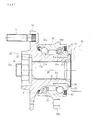
- Fig. 1 is a longitudinal section view showing a first embodiment of the wheel bearing apparatus for a vehicle of the present invention
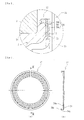
- Fig. 2 is a partially enlarged view of Fig. 1
- Fig. 3(a) is a front elevation view showing a cap of Fig. 2
- Fig. 3(b) is a cross-sectional view taken along a line III-III of Fig. 3(a)
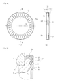
- Fig. 4(a) is a front elevation view showing one modification of the cap of Fig. 2
- Fig. 4(b) is a cross-sectional view taken along a line IV-IV of Fig. 4(a)
- Fig. 1 is a longitudinal section view showing a first embodiment of the wheel bearing apparatus for a vehicle of the present invention
- Fig. 2 is a partially enlarged view of Fig. 1
- Fig. 3(a) is a front elevation view showing a cap of Fig. 2
- Fig. 3(b) is a cross-sectional view taken along
- FIG. 5 is a partially enlarged view showing another modification of the cap of Fig. 2 .
- a term “outer side” of the apparatus denotes a side which is positioned outside of the vehicle body (the left-side in a drawing) and a term “inner side” of the apparatus denotes a side which is positioned inside of the body (the right-side in a drawing) when the bearing apparatus is mounted on the vehicle body.
- the bearing apparatus for a wheel of vehicle of the present invention is a third generation type used for a driven wheel and comprises an inner member 1, an outer member 10, and double row rolling elements (balls) 8, 8 for rollably contained between the inner and outer members 1, 10.
- the inner member 1 comprises a wheel hub 2 and an inner ring 3 secured on the wheel hub 2.
- the wheel hub 2 is integrally formed with a wheel mounting flange 4 at its one end, one (outer side) inner raceway surface 2a on its outer circumference, a cylindrical portion 2b axially extending from the inner raceway surface 2a, and a serration (or spline) 2c on its inner circumference.
- Hub bolts 5 are arranged on the wheel mounting flange 4 equidistantly along the periphery of the wheel mounting flange 4.
- the wheel hub 2 is made of medium/high carbon steel including carbon of 0.40 ⁇ 0.80% by weight such as S53C and hardened by high frequency induction quenching so that a region from an inner side base 7 of the wheel mounting flange 4 forming a seal-land portion to which an outer side seal 11 slide-contacts to the cylindrical portion 2b is hardened as having surface hardness of 58 ⁇ 64 HRC.
- the inner ring formed on its outer circumference with the other (inner side) inner raceway surface 3a is press-fitted onto the cylindrical portion 2b of the wheel hub 2 via a predetermined interference and axially immovably secured by a caulked portion 6 formed by plastically deforming the end of the cylindrical portion 2b radially outward.
- the end face of the caulked portion 6 is formed as a flat surface, it is possible to reduce the bearing pressure applied to the caulked portion by an axial force and thus to reduce a plastic deformation and wear of the caulked portion 6.
- the inner ring 3 and balls 8 are made of high carbon chrome steel such as SUJ2 and hardened to their core by dipping quenching so as to have a surface hardness of 58 ⁇ 64 HRC.
- the outer member 10 is integrally formed on its outer circumference with a body mounting flange 10b to be mounted on a body of a vehicle (not shown) and on its inner circumference with double row outer raceway surfaces 10a, 10a opposite to the inner raceway surfaces 2a, 3a of the inner member 1.
- the outer member 10 is made of medium/high carbon steel including carbon of 0.40 ⁇ 0.80%by weight such as S53C and at least the double row outer raceway surfaces 10a, 10a are hardened by high frequency induction quenching so as to have a surface hardness of 58 ⁇ 64 HRC.
- Double row balls 8, 8 are contained between these outer and inner raceway surfaces 10a, 2a and 10a, 3a of the outer member 10 and the inner member 1 and rollably held by cages 9, 9.
- Seals 11, 12 are mounted within annular openings formed between the outer member 10 and the inner member 1. These seals 8, 9 prevent leakage of grease contained in the bearing and enter of rainwater and dusts into the bearing from outside.
- a wheel bearing apparatus formed by a double row angular contact ball bearing using balls as rolling elements 8 the present invention is not limited to such a bearing and may be applied to a double row tapered roller bearing using tapered rollers as rolling elements 8.
- the structure shown here is a so-called third generation type bearing structure
- the wheel bearing apparatus of the present invention is not limited to such a structure and may be applied to bearing structures of so-called a first or second generation type in which a pair of inner rings are press-fitted onto a cylindrical portion of a wheel hub.
- the constant velocity universal joint 13 comprises an outer joint member 14, a joint inner ring, a cage and torque transmitting balls (not shown).
- the outer joint member 14 is made of medium/high carbon steel including carbon of 0.40 ⁇ 0.80% by weight such as S53C and comprises an integrally formed cup shaped mouth portion (not shown), a shoulder portion 15 forming a bottom of the mouth portion, and a stem portion 16 axially extending from the shoulder portion 15.
- the stem portion 16 is formed on its outer circumference with a serration (or spline) 16a engaging a serration 2c of the wheel hub 2 and on its end with an outer thread (male thread) 16b.
- the stem portion 16 of the outer joint member 14 is inserted into the wheel hub 2 until the shoulder portion 15 abuts against the caulked portion 6 via a cap 17 later described. Finally a securing nut 18 is fastened to the outer thread 16b at a predetermined fastening torque and the wheel hub 2 and the outer joint member 14 are axially separably connected each other.
- the cap 17 is mounted on the caulked portion 6 and secured with being sandwiched between the caulked portion 6 and the shoulder portion 15 of the outer joint member 14.
- the cap 17 comprises a core metal 20 and a molded portion 21 integrally adhered to the core metal 20 by injection molding.
- the core metal 20 is press-formed of a corrosion resistant steel sheet e.g. preserved cold rolled steel sheet (JIS SPCC etc.) or austenitic-stainless steel sheet (JIS SUS 304 etc.) as having a generally open ended ring shape having a substantially L-shaped cross-section. As shown in the enlarged view of Fig.
- the core metal 20 comprises a disc-shaped portion 20a, a cylindrical portion 20b axially extending from a radially outermost portion of the disc-shaped portion 20a, and an anchoring portion 20c projecting radially inward from the cylindrical portion 20b.
- the inner diameter of the anchoring portion 20c of the core metal 20 is set slightly smaller than the outer diameter of the caulked portion 6 so that the cap 17 can be easily snap-fitted on the caulked portion 6 by elastically enlarging the diameter of the anchoring portion 20c. Accordingly, it is possible to improve the workability of assembly by mounting the cap 17 on the caulked portion 6 with one-touch manner.
- the molded portion 21 is formed of fiber reinforced thermoplastic synthetic resin such as PA (polyamide) 66 etc. containing fibrous reinforcement such as GF (glass fiber) of 10 ⁇ 40 weight% and adhered to the inner-side surface of the disc-shaped portion 20a of the core metal 20 by injection molding.
- GF glass fiber
- the contents of GF less than 10 weight% cannot exhibit sufficient reinforcing effect
- the contents of GF exceeding 40 weight% causes anisotropy of fibers in a molded article and increases the density of GF and thus detracts the dimensional stability and toughness of the molded portion 21.
- the fibrous reinforcement is not limited to GF and other materials such as CF (carbon fiber), aramid fiber, boron fiber, etc. can be used as the fibrous reinforcement.
- the molded portion 21 can be formed, other than PA 66, e.g. of thermoplastic resin so-called as engineering plastic such as PPA (polyphthal amide), PBT (polybutylene terephthalate) etc., thermoplastic resin so-called as super engineering plastic such as polyphenylene sulfide (PPS), polyetheretherketon (PEEK), polyamideimide (PAI) etc., or thermosetting resin such as phenol resin (PF), epoxy resin (EP), polyimide resin (PI) etc.
- the molded portion 21 can be formed of biodegradable synthetic resin such as polylactic acid, polycaprolactone, polyglycol acid, denaturation polyvinyl alcohol, casein etc..
- the cap 17 is structured so that the core metal 20 of the cap 17 abuts against the end face of the caulked portion 6 and the molded portion 21 abuts against the shoulder portion 15 of the outer joint member 14 and an infinite number of micro indentations are formed on both surfaces of the core metal 20 and the molded portion 21.
- the surface of the core metal 20 adapted to be abutted against the caulked portion 6 is formed with indentations by shot blasting and treated as having the surface roughness of Ra 1.6 or less, preferably Ra 0.32 or less.
- Ra denotes one of the roughness shape parameters of JIS (JIS B0601-1994) and means arithmetic roughness average of absolute value deviations from the average line.
- an infinite number of micro indentations are formed also on the surface of the molded portion 21which is abutted against the shoulder portion 15 of the outer joint member 14.
- These indentations are formed by controlling a surface of the mold on molding and the surface roughness is set on Ra 1.6 or less, preferably Ra 0.32 or less.
- the surface roughness of the surfaces of the end face of the caulked portion 6 and the shoulder portion 15 of the outer joint member 14 is set on Ra 1.6 or less, preferably Ra 0.32 or less.
- the present invention is not limited to such a cap 17 and can be applied to a cap in which the outer-side surface of the disc-shaped portion 20a of the core metal is formed with the molded portion 21 and abutted against the shoulder portion 15 of the outer joint member 14 and the molded portion 21 is abutted against the end face of the caulked portion 6.
- This cap 22 also comprises a core metal 23 and a molded portion 24 integrally adhered to the core metal 23 by injection molding.
- the core metal 23 is press-formed of a corrosion resistant steel sheet e.g. preserved cold rolled steel sheet or austenitic-stainless steel sheet as having a ring shape having a substantially L-shaped cross-section.
- the core metal 23 comprises a disc-shaped portion 23a, a cylindrical portion 23b axially extending from a radially outermost portion of the disc-shaped portion 23a, and a plurality of claws (anchoring portion) 23c projecting radially inward from the cylindrical portion 23b.
- the claws 23c are arranged equidistantly along the periphery of the core metal 23 and the inner diameter formed by tip ends of the claws 23c of the core metal 23 is set slightly smaller than the outer diameter of the caulked portion so that the cap 22 can be easily snap-fitted on the caulked portion with one-touch manner by elastically enlarging the diameter of the claws 23c.
- the molded portion 24 is formed of fiber reinforced thermoplastic synthetic resin such as PA 66 etc. containing fibrous reinforcement such as CF of 5 ⁇ 40 weight% and adhered to the disc-shaped portion 23a of the core metal 23 by injection molding.
- fibrous reinforcement such as CF of 5 ⁇ 40 weight%
- the contents of CF less than 5 weight% cannot exhibit sufficient reinforcing effect
- the contents of CF exceeding 40 weight% causes reduction of toughness of the molded portion 24 and accordingly it is afraid that the molded portion 24 would be cracked or broken when the cap 22 is mounted on the caulked portion.
- Lubricant such as grease etc. is applied between the caulked portion 6 and the shoulder portion 15 of the outer joint member 14 and a number of through apertures 25 are formed on the disc-shaped portion 23a of the core metal 23.
- the through apertures 25 can hold the lubricant applied to the abutting surfaces and thus to further reduce the coefficients of friction of the abutting surfaces and further effectively prevent generation of the stick-slip noise.
- Fig. 5 shows another modification of the cap 17 of Fig. 2 .
- This cap 26 comprises a core metal 27 and the molded portion 28 integrally adhered to the core metal 27 by injection molding.
- the core metal 27 is press-formed of a corrosion resistant steel sheet e.g. preserved cold rolled steel sheet or austenitic-stainless steel sheet as having a generally open ended ring shape having a substantially L-shaped cross-section and comprises a disc-shaped portion 27a, the cylindrical portion 20b axially extending from a radially outermost portion of the disc-shaped portion 20a, and the anchoring portion 20c projecting radially inward from the cylindrical portion 20b.
- a corrosion resistant steel sheet e.g. preserved cold rolled steel sheet or austenitic-stainless steel sheet as having a generally open ended ring shape having a substantially L-shaped cross-section and comprises a disc-shaped portion 27a, the cylindrical portion 20b axially extending from a radially outermost portion of the disc-shaped portion 20
- the core metal 27 of this embodiment is abutted against the caulked portion 29 and the molded portion 28 is abutted against the shoulder portion 15 and the surfaces of the core metal 27 and the mold portion 28 are formed with an infinite number of micro indentations.
- the end face of the caulked portion 29 is formed with an annular groove 29a, and the disc-shaped portion 27a of the core metal 27 is formed with an annular projection 30 axially projected therefrom so as to be engaged with the annular groove 29a.
- the present invention can be applied to a wheel bearing apparatus of the first through third generations comprising an inner member including a wheel hub and an inner ring and a constant velocity universal joint in which the inner member and an outer joint member of the constant velocity universal joint are separably fastened in an abutted condition.
Landscapes
- Engineering & Computer Science (AREA)
- Mechanical Engineering (AREA)
- General Engineering & Computer Science (AREA)
- Rolling Contact Bearings (AREA)
- Mounting Of Bearings Or Others (AREA)
Abstract
An object of the present invention is to provide a wheel bearing apparatus for a vehicle which can reduce the sudden slip between the inner member (particularly the caulked portion) and the shoulder portion of the outer joint member and thus can prevent generation of the stick-slip noise. According to the present invention, there is provided a wheel bearing apparatus for a vehicle comprising an outer member integrally formed on its inner circumference with double row outer raceway surfaces; an inner member including a wheel hub and at least one inner ring; seals mounted in openings of annular space formed between the outer member and the inner member; the inner ring being axially immovably secured relative to the wheel hub by a caulked portion formed by plastically deforming an end of the cylindrical portion radially outward; a constant velocity universal joint connected to the wheel hub; an outer joint member of the constant velocity universal joint comprising a cup-shaped mouth portion, a shoulder portion forming a bottom of the mouth portion, and a stem portion fitted into the wheel hub via serrations with a torque transmittable manner; and the wheel hub and the outer joint member being axially detachably connected with the shoulder portion being abutted against the caulked portion characterized in that the end face of the caulked portion is formed as having a flat surface and a cap is mounted on the caulked portion; and that the cap comprises a core metal press-formed of a corrosion resistant steel sheet as having a generally ring shape having a substantially L-shaped cross-section, the inner diameter of the core metal being set slightly smaller than the outer diameter of the caulked portion, and a molded portion formed of synthetic resin having on its surface an infinite number of micro indentations, the cap being abutted against the end face of the caulked portion and the shoulder portion of the outer joint member.
Description
- The present invention relates to a wheel bearing apparatus for a vehicle for supporting a wheel of a vehicle such as an automobile, and more particularly to a wheel bearing apparatus including a wheel bearing and a constant velocity universal joint for rotationally supporting a driving wheel (front wheel of an FF vehicle, a rear wheel of an FR or RR vehicle and whole wheels of 4WD vehicle) mounted on an independent suspension relative to the suspension apparatus.
- In a power transmitting apparatus for transmitting an engine power of a vehicle such as an automobile to wheels, it is necessary not only to transmit the power from an engine to wheels, but to allow radial and axial displacements and a moment displacement from wheels caused by bounds or turns of a vehicle during running on a rough road. Accordingly the power transmitting apparatus is connected to the driving wheel via a wheel bearing apparatus including a constant velocity universal joint in which one end of a driving shaft arranged between an engine side and the driving wheel side is connected to a differential gear unit via a constant velocity universal joint of a sliding type and the other end thereof is a secured type.
- It is known in such a vehicle that a large torque is transmitted to its wheels from the engine via the constant velocity universal joint of sliding type on start of vehicle at a low engine speed and accordingly torsion is caused in the driving shaft. As the result of which, the torsion is also caused in an inner member of the wheel bearing for supporting the driving shaft and thus the stick-slip noise is caused by a sudden slip between abutting surfaces of an outer joint member of the constant velocity universal joint and the inner member when the large torsion is caused in the driving shaft.
- For coping with this problem, it is known a wheel bearing apparatus for example shown in
Fig. 6 . This wheel bearing apparatus comprises aninner member 51, anouter member 60,double row balls outer members universal joint 63 detachably connected to a wheel bearing. The inner member comprises awheel hub 52 and aninner ring 53 press-fitted onto thewheel hub 52. - The
wheel hub 52 is integrally formed with awheel mounting flange 54 on its one end for mounting a wheel (not shown) and also formed with oneinner raceway surface 52a on its outer circumference and acylindrical portion 52b axially extending from theinner raceway surface 52a and additionally formed with aserration 52c on its inner circumference for torque transmission.Hub bolts 55 are arranged equidistantly along the periphery of thewheel mounting flange 54. - The
inner ring 53 formed on its outer circumference with the otherinner raceway surface 53a is press-fitted onto thecylindrical portion 52b of thewheel hub 52 and axially secured thereon by acaulked portion 56 formed by plastically deforming the end of thecylindrical portion 52b radially outward. - The
outer member 60 is integrally formed on its outer circumference with abody mounting flange 60b to be mounted on a body of a vehicle (not shown) and on its inner circumference with double rowouter raceway surfaces inner raceway surfaces inner member 51.Double row balls inner raceway surfaces outer member 60 and theinner member 51 and rollably held bycages Seals outer member 60 and theinner member 51. Theseseals - The constant velocity
universal joint 63 comprises anouter joint member 64, a joint inner ring and torque transmitting balls (not shown). Theouter joint member 64 is integrally formed with a cup shaped mouth portion (not shown), ashoulder portion 65 forming a bottom of the mouth portion, and astem portion 66 axially extending from theshoulder portion 65. Thestem portion 66 is formed on its outer circumference with aserration 66a engaging with aserration 52a formed on thewheel hub 52 and formed with anexternal thread 66b on the end of theserration 66a. Thestem portion 66 of theouter joint member 64 is inserted into thewheel hub 52 until theshoulder portion 65 abuts against thecaulked portion 56 of thewheel hub 51 via acap 67 hereinafter described and then asecuring nut 68 is fastened onto anexternal thread 66b with a predetermined fastening torque to enable thewheel hub 52 and theouter joint member 64 to be detachably connected. - The
cap 67 is secured with being sandwiched between the caulked 56 and theshoulder portion 65 of theouter joint member 64. Thecap 67 is press-formed of austenitic-stainless steel sheet having corrosion resistance and the surface roughness of 0.63 or less so as to have a substantially L-shaped cross-section. - As shown in an enlarged view of
Fig. 7 , thecap 67 comprises a disc shapedabutting portion 67a, acylindrical portion 67b axially extending from a radially outermost portion of theabutting portion 67a, and ananchoring portion 67c bent radially inward from the end of thecylindrical portion 67b. The inner diameter of theanchoring portion 67c of thecap 17 is set slightly smaller than the outer diameter of thecaulked portion 56 and adapted to be mounted on thecaulked portion 56 by elastically deforming theanchoring portion 67c. This enables one-touch mounting of thecap 67 onto thecaulked portion 56 and thus enables to prevent thecap 67 from being slipped off from thecaulked portion 56 during assembling step. In addition, it is possible to prevent generation of the stick-slip noise due to reduction of the coefficient of friction and thus suppression of sudden slip generated between thecaulked portion 56 and the shoulder portion 65 (see e.g. Patent Document 1 below). - Patent Document 1 : Japanese Laid-open Patent Publication No.
296841/2008 - However, in the wheel bearing apparatus for a vehicle of the prior art, it is afraid that adhesion due to metal-to-metal contact would be caused in abutting surfaces between opposite surfaces of the
cap 67 and a surface of theshoulder portion 65 of theouter joint member 64 and/or a surface of thecaulked portion 56 and accordingly the stick-slip noise would be caused when the adhesion is broken. - It is, therefore, an object of the present invention to provide a wheel bearing apparatus for a vehicle which can reduce the sudden slip between the inner member (particularly the caulked portion) and the shoulder portion of the outer joint member and thus can prevent generation of the stick-slip noise.
- For achieving the object of the present invention, there is provided, according to claim 1 of the present invention, a wheel bearing apparatus for a vehicle comprising an outer member integrally formed on its inner circumference with double row outer raceway surfaces; an inner member including a wheel hub and at least one inner ring and being formed with double row inner raceway surfaces arranged oppositely to the double row outer raceway surfaces, the wheel hub being integrally formed on its one end with a wheel mounting flange and on its other end with an axially extending cylindrical portion, and the inner ring being press fitted onto the cylindrical portion of the wheel hub; double row rolling elements rollably contained between the double row inner and outer raceway surfaces of the inner member and the outer member via cages; seals mounted in openings of annular space formed between the outer member and the inner member; the inner ring being axially immovably secured relative to the wheel hub by a caulked portion formed by plastically deforming an end of the cylindrical portion radially outward; a constant velocity universal joint connected to the wheel hub; an outer joint member of the constant velocity universal joint comprising a cup-shaped mouth portion, a shoulder portion forming a bottom of the mouth portion, and a stem portion fitted into the wheel hub via serrations with a torque transmittable manner; and the wheel hub and the outer joint member being axially detachably connected with the shoulder portion being abutted against the caulked portion characterized in that the end face of the caulked portion is formed as having a flat surface and a cap is mounted on the caulked portion; and that the cap comprises a core metal press-formed of a corrosion resistant steel sheet as having a generally ring shape having a substantially L-shaped cross-section, and a molded portion formed of synthetic resin having on its surface an infinite number of micro indentations, the cap being abutted against the end face of the caulked portion and the shoulder portion of the outer joint member.
- According to the wheel bearing apparatus for a vehicle of claim 1 of the present invention, since the inner ring being axially immovably secured relative to the wheel hub by a caulked portion formed by plastically deforming an end of the cylindrical portion of the wheel hub radially outward; a constant velocity universal joint connected to the wheel hub; an outer joint member of the constant velocity universal joint comprising a cup-shaped mouth portion, a shoulder portion forming a bottom of the mouth portion, and a stem portion fitted into the wheel hub via serrations with a torque transmittable manner; and the wheel hub and the outer joint member being axially detachably connected with the shoulder portion being abutted against the caulked portion characterized in that the end face of the caulked portion is formed as having a flat surface and a cap is mounted on the caulked portion; and that the cap comprises a core metal press-formed of a corrosion resistant steel sheet as having a generally ring shape having a substantially L-shaped cross-section, and a molded portion formed of synthetic resin having on its surface an infinite number of micro indentations, the cap being abutted against the end face of the caulked portion and the shoulder portion of the outer joint member, it is possible not only to suppress wear of the cap and thus to improve its durability but also to prevent generation of the stick-slip noise by reducing a sudden slip generated between the caulked portion and the shoulder portion of the outer joint member with reducing the coefficients of friction of the abutting surfaces.
- It is preferable as defined in
claim 2 that the molded portion has the surface roughness of Ra 1.6 or less. This enables to prevent the generation of the stick-slip noise by reducing the coefficient of friction. - It is preferable as defined in
claim 3 that the surface of the core metal is formed with an infinite number of micro indentations. This enables to further effectively prevent the generation of the stick-slip noise by reducing a sudden slip generated between the caulked portion and the shoulder portion of the outer joint member with reducing the coefficients of friction of the abutting surfaces. - It is also preferable as defined in claim 4 that the indentations of the core metal are formed by shot blasting and have the surface roughness of Ra 1.6 or less. This enables to reduce the coefficient of friction and thus to prevent generation of the stick-slip noise.
- It is preferable as defined in
claim 5 that the core metal comprises a disc-shaped portion, a cylindrical portion axially extending from a radially outermost portion of the disc-shaped portion, and an anchoring portion projecting radially inward from the cylindrical portion, that the molded portion is adhered to the disc-shaped portion, and that the inner diameter of the anchoring portion of the core metal is set slightly smaller than the outer diameter of the caulked portion. This makes it possible to easily mount the cap onto the caulked portion by a snap-fit manner and accordingly to improve the workability in assembly. - It is also preferable as defined in
claim 6 that the core metal is formed as an open ended ring shape or as defined inclaim 7 that a plurality of the anchoring portions are formed equidistantly along the periphery of the core metal. - It is preferable as defined in
claim 8 that lubricant is applied between the caulked portion and the shoulder portion of the outer joint member. This enables to reduce the coefficients of friction of the abutting surfaces and thus to further effectively prevent generation of the stick-slip noise as well as to suppress wear of the caulked portion and the cap. - It is preferable as defined in
claim 9 that a number of through apertures are formed on the disc-shaped portion of the core metal. This makes it possible to hold the lubricant applied to the abutting surfaces in the through apertures and thus to further reduce the coefficients friction of the abutting surfaces and accordingly wears thereof. - It is also preferable as defined in
claim 10 that the end face of the caulked portion and the shoulder portion of the outer joint member have the surface roughness of Ra 1.6 or less. This enables to suppress wear of the cap and thus to improve its durability. - It is preferable as defined in
claim 11 that the end face of the caulked portion is formed with an annular groove, and that the disc-shaped portion of the core metal is formed with an annular projection axially projected therefrom so as to be engaged with the annular groove. This makes it possible to easily achieve a radial positioning of the cap relative to the caulked portion, to prevent slipping-off of the cap during transportation or assembly of the wheel bearing, to surely prevent tilted mount of the cap during its assembly, and thus to improve the reliability of assembly. - It is preferable as defined in
claim 12 that the molded portion is formed of fiber reinforced thermoplastic synthetic resin. This enables to reduce the coefficient of friction and accordingly the wear of the molded portion, and to improve its strength and durability. - It is also preferable as defined in
claim 13 that the molded portion is formed of biodegradable synthetic resin. This enables to reduce the environmental load. - According to the wheel bearing apparatus for a vehicle of the present invention, since it comprises an outer member integrally formed on its inner circumference with double row outer raceway surfaces; an inner member including a wheel hub and at least one inner ring and being formed with double row inner raceway surfaces arranged oppositely to the double row outer raceway surfaces, the wheel hub being integrally formed on its one end with a wheel mounting flange and on its other end with an axially extending cylindrical portion, and the inner ring being press fitted onto the cylindrical portion of the wheel hub; double row rolling elements rollably contained between the double row inner and outer raceway surfaces of the inner member and the outer member via cages; seals mounted in openings of annular space formed between the outer member and the inner member; the inner ring being axially immovably secured relative to the wheel hub by a caulked portion formed by plastically deforming an end of the cylindrical portion radially outward; a constant velocity universal joint connected to the wheel hub; an outer joint member of the constant velocity universal joint comprising a cup-shaped mouth portion, a shoulder portion forming a bottom of the mouth portion, and a stem portion fitted into the wheel hub via serrations with a torque transmittable manner; and the wheel hub and the outer joint member being axially detachably connected with the shoulder portion being abutted against the caulked portion and is characterized in that the end face of the caulked portion is formed as having a flat surface and a cap is mounted on the caulked portion; and that the cap comprises a core metal press-formed of a corrosion resistant steel sheet as having a generally ring shape having a substantially L-shaped cross-section, and a molded portion formed of synthetic resin having on its surface an infinite number of micro indentations, the cap being abutted against the end face of the caulked portion and the shoulder portion of the outer joint member, it is possible not only to suppress wear of the cap and thus to improve its durability but also to prevent generation of the stick-slip noise by reducing a sudden slip generated between the caulked portion and the shoulder portion of the outer joint member with reducing the coefficients of friction of the abutting surfaces.
-
- [
Fig. 1 ] A longitudinal section view showing a first embodiment of the wheel bearing apparatus for a vehicle of the present invention; - [
Fig. 2 ] A partially enlarged view ofFig. 1 ; - [
Fig. 3 ] (a) a front elevation view showing a cap ofFig. 2 , and (b) a cross-sectional view taken along a line III-III of Fig. 3(a); - [
Fig. 4 ] (a) a front elevation view showing one modification of the cap ofFig. 2 , and (b) a cross-sectional view taken along a line IV-IV ofFig. 4(a) ; - [
Fig. 5 ] A partially enlarged view showing another modification of the cap ofFig. 2 ; - [
Fig. 6 ] A longitudinal section view showing a wheel bearing apparatus for a vehicle of the prior art; and - [
Fig. 7 ] A partially enlarged view ofFig. 6 . - One preferable mode for carrying out the present invention is a wheel bearing apparatus for a vehicle comprising an outer member integrally formed on its outer circumference with a body mounting flange and on its inner circumference with double row outer raceway surfaces; an inner member including a wheel hub and an inner ring, the wheel hub being integrally formed on its one end with a wheel mounting flange, on its outer circumference with one inner raceway surface corresponding to one of the outer raceway surface and on its other end with a cylindrical portion, and the inner ring being press fitted onto the cylindrical portion of the wheel hub and being formed with the other inner raceway surface corresponding to the other of the double row outer raceway surfaces; double row rolling elements rollably contained between the double row inner and outer raceway surfaces of the inner member and the outer member via cages; seals mounted in openings of annular space formed between the outer member and the inner member; the inner ring being axially immovably secured relative to the wheel hub by a caulked portion formed by plastically deforming an end of the cylindrical portion radially outward; a constant velocity universal joint connected to the wheel hub; an outer joint member of the constant velocity universal joint comprising a cup-shaped mouth portion, a shoulder portion forming a bottom of the mouth portion, and a stem portion fitted into the wheel hub via serrations with a torque transmittable manner; and the wheel hub and the outer joint member being axially detachably connected with the shoulder portion being abutted against the caulked portion characterized in that the end face of the caulked portion is formed as having a flat surface and a cap is mounted on the caulked portion; and that the cap comprises a core metal press-formed of a corrosion resistant steel sheet as having a generally ring shape having a substantially L-shaped cross-section, and a molded portion formed of synthetic resin having on its surface an infinite number of micro indentations, the cap being abutted against the end face of the caulked portion and the shoulder portion of the outer joint member.
- Preferable embodiments of the present invention will be hereinafter described with reference to the drawings.
Fig. 1 is a longitudinal section view showing a first embodiment of the wheel bearing apparatus for a vehicle of the present invention,Fig. 2 is a partially enlarged view ofFig. 1 , Fig. 3(a) is a front elevation view showing a cap ofFig. 2 , and Fig. 3(b) is a cross-sectional view taken along a line III-III of Fig. 3(a),Fig. 4(a) is a front elevation view showing one modification of the cap ofFig. 2 , andFig. 4(b) is a cross-sectional view taken along a line IV-IV ofFig. 4(a), and Fig. 5 is a partially enlarged view showing another modification of the cap ofFig. 2 . In the description below, a term "outer side" of the apparatus denotes a side which is positioned outside of the vehicle body (the left-side in a drawing) and a term "inner side" of the apparatus denotes a side which is positioned inside of the body (the right-side in a drawing) when the bearing apparatus is mounted on the vehicle body. - The bearing apparatus for a wheel of vehicle of the present invention is a third generation type used for a driven wheel and comprises an inner member 1, an
outer member 10, and double row rolling elements (balls) 8, 8 for rollably contained between the inner andouter members 1, 10. The inner member 1 comprises awheel hub 2 and aninner ring 3 secured on thewheel hub 2. - The
wheel hub 2 is integrally formed with a wheel mounting flange 4 at its one end, one (outer side)inner raceway surface 2a on its outer circumference, acylindrical portion 2b axially extending from theinner raceway surface 2a, and a serration (or spline) 2c on its inner circumference.Hub bolts 5 are arranged on the wheel mounting flange 4 equidistantly along the periphery of the wheel mounting flange 4. - The
wheel hub 2 is made of medium/high carbon steel including carbon of 0.40∼0.80% by weight such as S53C and hardened by high frequency induction quenching so that a region from aninner side base 7 of the wheel mounting flange 4 forming a seal-land portion to which anouter side seal 11 slide-contacts to thecylindrical portion 2b is hardened as having surface hardness of 58∼64 HRC. The inner ring formed on its outer circumference with the other (inner side) inner raceway surface 3a is press-fitted onto thecylindrical portion 2b of thewheel hub 2 via a predetermined interference and axially immovably secured by a caulkedportion 6 formed by plastically deforming the end of thecylindrical portion 2b radially outward. Since the end face of the caulkedportion 6 is formed as a flat surface, it is possible to reduce the bearing pressure applied to the caulked portion by an axial force and thus to reduce a plastic deformation and wear of the caulkedportion 6. On the other hand theinner ring 3 andballs 8 are made of high carbon chrome steel such as SUJ2 and hardened to their core by dipping quenching so as to have a surface hardness of 58∼64 HRC. - The
outer member 10 is integrally formed on its outer circumference with abody mounting flange 10b to be mounted on a body of a vehicle (not shown) and on its inner circumference with double rowouter raceway surfaces inner raceway surfaces 2a, 3a of the inner member 1. Theouter member 10 is made of medium/high carbon steel including carbon of 0.40∼0.80%by weight such as S53C and at least the double rowouter raceway surfaces Double row balls inner raceway surfaces outer member 10 and the inner member 1 and rollably held bycages Seals outer member 10 and the inner member 1. Theseseals - Although it is shown herein a wheel bearing apparatus formed by a double row angular contact ball bearing using balls as rolling
elements 8, the present invention is not limited to such a bearing and may be applied to a double row tapered roller bearing using tapered rollers as rollingelements 8. In addition although the structure shown here is a so-called third generation type bearing structure, the wheel bearing apparatus of the present invention is not limited to such a structure and may be applied to bearing structures of so-called a first or second generation type in which a pair of inner rings are press-fitted onto a cylindrical portion of a wheel hub. - The constant velocity
universal joint 13 comprises an outerjoint member 14, a joint inner ring, a cage and torque transmitting balls (not shown). The outerjoint member 14 is made of medium/high carbon steel including carbon of 0.40∼0.80% by weight such as S53C and comprises an integrally formed cup shaped mouth portion (not shown), ashoulder portion 15 forming a bottom of the mouth portion, and astem portion 16 axially extending from theshoulder portion 15. Thestem portion 16 is formed on its outer circumference with a serration (or spline) 16a engaging aserration 2c of thewheel hub 2 and on its end with an outer thread (male thread) 16b. Thestem portion 16 of the outerjoint member 14 is inserted into thewheel hub 2 until theshoulder portion 15 abuts against the caulkedportion 6 via acap 17 later described. Finally a securingnut 18 is fastened to theouter thread 16b at a predetermined fastening torque and thewheel hub 2 and the outerjoint member 14 are axially separably connected each other. - The
cap 17 is mounted on the caulkedportion 6 and secured with being sandwiched between the caulkedportion 6 and theshoulder portion 15 of the outerjoint member 14. Thecap 17 comprises a core metal 20 and a moldedportion 21 integrally adhered to the core metal 20 by injection molding. The core metal 20 is press-formed of a corrosion resistant steel sheet e.g. preserved cold rolled steel sheet (JIS SPCC etc.) or austenitic-stainless steel sheet (JIS SUS 304 etc.) as having a generally open ended ring shape having a substantially L-shaped cross-section. As shown in the enlarged view ofFig. 2 , the core metal 20 comprises a disc-shapedportion 20a, acylindrical portion 20b axially extending from a radially outermost portion of the disc-shapedportion 20a, and an anchoringportion 20c projecting radially inward from thecylindrical portion 20b. The inner diameter of the anchoringportion 20c of the core metal 20 is set slightly smaller than the outer diameter of the caulkedportion 6 so that thecap 17 can be easily snap-fitted on the caulkedportion 6 by elastically enlarging the diameter of the anchoringportion 20c. Accordingly, it is possible to improve the workability of assembly by mounting thecap 17 on the caulkedportion 6 with one-touch manner. - On the other hand, the molded
portion 21 is formed of fiber reinforced thermoplastic synthetic resin such as PA (polyamide) 66 etc. containing fibrous reinforcement such as GF (glass fiber) of 10∼40 weight% and adhered to the inner-side surface of the disc-shapedportion 20a of the core metal 20 by injection molding. In this case, the contents of GF less than 10 weight% cannot exhibit sufficient reinforcing effect, on the other hand the contents of GF exceeding 40 weight% causes anisotropy of fibers in a molded article and increases the density of GF and thus detracts the dimensional stability and toughness of the moldedportion 21. Accordingly, it is afraid that the moldedportion 21 would be cracked or broken by elastic deformation of the core metal 20 when thecap 17 is mounted on the caulkedportion 6. The fibrous reinforcement is not limited to GF and other materials such as CF (carbon fiber), aramid fiber, boron fiber, etc. can be used as the fibrous reinforcement. - The molded
portion 21 can be formed, other thanPA 66, e.g. of thermoplastic resin so-called as engineering plastic such as PPA (polyphthal amide), PBT (polybutylene terephthalate) etc., thermoplastic resin so-called as super engineering plastic such as polyphenylene sulfide (PPS), polyetheretherketon (PEEK), polyamideimide (PAI) etc., or thermosetting resin such as phenol resin (PF), epoxy resin (EP), polyimide resin (PI) etc.. Furthermore, in order to reduce the environmental load, the moldedportion 21 can be formed of biodegradable synthetic resin such as polylactic acid, polycaprolactone, polyglycol acid, denaturation polyvinyl alcohol, casein etc.. - According to the present invention, the
cap 17 is structured so that the core metal 20 of thecap 17 abuts against the end face of the caulkedportion 6 and the moldedportion 21 abuts against theshoulder portion 15 of the outerjoint member 14 and an infinite number of micro indentations are formed on both surfaces of the core metal 20 and the moldedportion 21. In particular, as shown inFig. 3 the surface of the core metal 20 adapted to be abutted against the caulkedportion 6 is formed with indentations by shot blasting and treated as having the surface roughness of Ra 1.6 or less, preferably Ra 0.32 or less. Herein, "Ra" denotes one of the roughness shape parameters of JIS (JIS B0601-1994) and means arithmetic roughness average of absolute value deviations from the average line. - On the other hand, an infinite number of micro indentations are formed also on the surface of the molded portion 21which is abutted against the
shoulder portion 15 of the outerjoint member 14. These indentations are formed by controlling a surface of the mold on molding and the surface roughness is set on Ra 1.6 or less, preferably Ra 0.32 or less. In addition, the surface roughness of the surfaces of the end face of the caulkedportion 6 and theshoulder portion 15 of the outerjoint member 14 is set on Ra 1.6 or less, preferably Ra 0.32 or less. The provision of such acap 17 makes it possible to suppress wear of thecap 17 and thus to improve its durability. Furthermore, it is possible to reduce the coefficient of friction of each abutting surface and thus to suppress wear of the caulkedportion 6, and to prevent generation of the stick-slip noise with reducing sudden slip caused between the caulkedportion 6 and theshoulder portion 15 of the outerjoint member 14. - Although it is shown, as one example, the
cap 17 in which the moldedportion 21 is abutted against theshoulder portion 15 of the outerjoint member 14 and the side surface of the core metal 20 not having the moldedportion 21 is abutted against the end face of the caulkedportion 6, the present invention is not limited to such acap 17 and can be applied to a cap in which the outer-side surface of the disc-shapedportion 20a of the core metal is formed with the moldedportion 21 and abutted against theshoulder portion 15 of the outerjoint member 14 and the moldedportion 21 is abutted against the end face of the caulkedportion 6. - Then, one modification of the
cap 17 ofFig. 2 is shown inFig. 4 . Thiscap 22 also comprises acore metal 23 and a moldedportion 24 integrally adhered to thecore metal 23 by injection molding. Thecore metal 23 is press-formed of a corrosion resistant steel sheet e.g. preserved cold rolled steel sheet or austenitic-stainless steel sheet as having a ring shape having a substantially L-shaped cross-section. Thecore metal 23 comprises a disc-shapedportion 23a, acylindrical portion 23b axially extending from a radially outermost portion of the disc-shapedportion 23a, and a plurality of claws (anchoring portion) 23c projecting radially inward from thecylindrical portion 23b. Theclaws 23c are arranged equidistantly along the periphery of thecore metal 23 and the inner diameter formed by tip ends of theclaws 23c of thecore metal 23 is set slightly smaller than the outer diameter of the caulked portion so that thecap 22 can be easily snap-fitted on the caulked portion with one-touch manner by elastically enlarging the diameter of theclaws 23c. - On the other hand, the molded
portion 24 is formed of fiber reinforced thermoplastic synthetic resin such asPA 66 etc. containing fibrous reinforcement such as CF of 5∼40 weight% and adhered to the disc-shapedportion 23a of thecore metal 23 by injection molding. In this case, the contents of CF less than 5 weight% cannot exhibit sufficient reinforcing effect, on the other hand the contents of CF exceeding 40 weight% causes reduction of toughness of the moldedportion 24 and accordingly it is afraid that the moldedportion 24 would be cracked or broken when thecap 22 is mounted on the caulked portion. - Lubricant such as grease etc. is applied between the caulked
portion 6 and theshoulder portion 15 of the outerjoint member 14 and a number of throughapertures 25 are formed on the disc-shapedportion 23a of thecore metal 23. The throughapertures 25 can hold the lubricant applied to the abutting surfaces and thus to further reduce the coefficients of friction of the abutting surfaces and further effectively prevent generation of the stick-slip noise. -
Fig. 5 shows another modification of thecap 17 ofFig. 2 . Thiscap 26 comprises acore metal 27 and the moldedportion 28 integrally adhered to thecore metal 27 by injection molding. Thecore metal 27 is press-formed of a corrosion resistant steel sheet e.g. preserved cold rolled steel sheet or austenitic-stainless steel sheet as having a generally open ended ring shape having a substantially L-shaped cross-section and comprises a disc-shapedportion 27a, thecylindrical portion 20b axially extending from a radially outermost portion of the disc-shapedportion 20a, and the anchoringportion 20c projecting radially inward from thecylindrical portion 20b. - Similarly to the previously described embodiments, the
core metal 27 of this embodiment is abutted against the caulkedportion 29 and the moldedportion 28 is abutted against theshoulder portion 15 and the surfaces of thecore metal 27 and themold portion 28 are formed with an infinite number of micro indentations. Furthermore, the end face of the caulkedportion 29 is formed with anannular groove 29a, and the disc-shapedportion 27a of thecore metal 27 is formed with anannular projection 30 axially projected therefrom so as to be engaged with theannular groove 29a. This makes it possible to easily achieve a radial positioning of thecap 26 relative to the caulkedportion 29, to prevent slipping-off of thecap 26 during transportation or assembly of the wheel bearing, to surely prevent tilted mount of thecap 26 during its assembly, and thus to improve the reliability of assembly. - The present invention has been described with reference to the preferred embodiments. Obviously, modifications and alternations will occur to those of ordinary skill in the art upon reading and understanding the preceding detailed description. It is intended that the present invention be construed as including all such alternations and modifications insofar as they come within the scope of the appended claims or the equivalents thereof.
- The present invention can be applied to a wheel bearing apparatus of the first through third generations comprising an inner member including a wheel hub and an inner ring and a constant velocity universal joint in which the inner member and an outer joint member of the constant velocity universal joint are separably fastened in an abutted condition. Descriptions of reference numerals
-
- 1
- inner member
- 2
- wheel hub
- 2a, 3a
- inner raceway surface
- 2b
- cylindrical portion
- 2c, 16a
- serration
- 3
- inner ring
- 4
- wheel mounting flange
- 5
- hub bolt
- 6, 29
- caulked portion
- 7
- base of wheel mounting flange
- 8
- rolling element
- 9
- cage
- 10
- outer member
- 10a
- outer raceway surface
- 10b
- body mounting flange
- 11
- outer-side seal
- 12
- inner-side seal
- 13
- constant velocity universal joint
- 14
- outer joint member
- 15
- shoulder portion
- 16
- stem portion
- 16b
- external thread
- 17, 22, 26
- cap
- 18
- washer
- 19
- securing nut
- 20, 23, 27
- core metal
- 20a, 23a, 27a
- disc-shaped portion
- 20b, 23b
- anchoring portion
- 21, 24, 28
- molded portion
- 25
- through aperture
- 29a
- annular groove
- 30
- projection
- 51
- inner member
- 52
- wheel hub
- 52a, 53a
- inner raceway surface
- 52b
- cylindrical portion
- 52c, 66a
- serration
- 53
- inner ring
- 54
- wheel mounting flange
- 55
- hub bolt
- 56
- caulked portion
- 58
- ball
- 59
- cage
- 60
- outer member
- 60a
- outer raceway surface
- 60b
- body mounting flange
- 61
- outer-side seal
- 62
- inner-side seal
- 63
- constant velocity universal joint
- 64
- outer joint member
- 65
- shoulder portion
- 66
- stem portion
- 66b
- external thread
- 67
- cap
- 67a
- abutting portion
- 67b
- cylindrical portion
- 67c
- anchoring portion
- 68
- securing nut
Claims (13)
- A wheel bearing apparatus for a vehicle comprising:an outer member (10) integrally formed on its inner circumference with double row outer raceway surfaces (10a, 10a);an inner member (1) including a wheel hub (2) and at least one inner ring (3) and being formed with double row inner raceway surfaces (2a, 3a) arranged oppositely to the double row outer raceway surfaces (10a, 10a), the wheel hub (2) being integrally formed on its one end with a wheel mounting flange (4) and on its other end with an axially extending cylindrical portion (2b), and the inner ring (3) being press fitted onto the cylindrical portion (2b) of the wheel hub (2);double row rolling elements (8, 8) rollably contained between the double row inner and outer raceway surfaces (2a, 3a and 10a, 10a) of the inner member (1) and the outer member (10) via cages (9);seals (11, 12) mounted in openings of annular space formed between the outer member (10) and the inner member (1);the inner ring (3) being axially immovably secured relative to the wheel hub (2) by a caulked portion (6, 29) formed by plastically deforming an end of the cylindrical portion (2b) radially outward;a constant velocity universal joint (13) connected to the wheel hub (2);an outer joint member (14) of the constant velocity universal joint (13) comprising a cup-shaped mouth portion, a shoulder portion (15) forming a bottom of the mouth portion, and a stem portion (16) fitted into the wheel hub (2) via serrations (2c, 16a) with a torque transmittable manner; andthe wheel hub (2) and the outer joint member (14) being axially detachably connected with the shoulder portion (15) being abutted against the caulked portion (6, 29) characterized in:that the end face of the caulked portion (6, 29) is formed as having a flat surface and a cap (17, 22, 26) is mounted on the caulked portion (6, 29); andthat the cap (17, 22, 26) comprises a core metal (20, 23, 27) press-formed of a corrosion resistant steel sheet as having a generally ring shape having a substantially L-shaped cross-section, and a molded portion (21, 24, 28) formed of synthetic resin having on its surface an infinite number of micro indentations, the cap (17, 22, 26) being abutted against the end face of the caulked portion (6, 29) and the shoulder portion (15) of the outer joint member (14).
- A wheel bearing apparatus for a vehicle of claim 1 wherein the molded portion (21, 24, 28) has the surface roughness of Ra 1.6 or less.
- A wheel bearing apparatus for a vehicle of claim 1 or 2 wherein the surface of the core metal (20, 23, 27) is formed with an infinite number of micro indentations.
- A wheel bearing apparatus for a vehicle of claim 3 wherein the indentations of the core metal (20, 23, 27) are formed by shot blasting and have the surface roughness of Ra 1.6 or less.
- A wheel bearing apparatus for a vehicle of claim 1 wherein the core metal (20, 23, 27) comprises a disc-shaped portion (20a, 23a, 27a), a cylindrical portion (20b, 23b) axially extending from a radially outermost portion of the disc-shaped portion (20a, 23a, 27a), and an anchoring portion (20c, 23c) projecting radially inward from the cylindrical portion (20b, 23b), wherein the molded portion (21, 24, 28) is adhered to the disc-shaped portion (20a, 23a, 27a), and wherein the inner diameter of the anchoring portion (20c, 23c) of the core metal (20, 23, 27) is set slightly smaller than the outer diameter of the caulked portion (6, 29).
- A wheel bearing apparatus for a vehicle of claim 5 wherein the core metal (20) is formed as an open ended ring shape.
- A wheel bearing apparatus for a vehicle of claim 5 wherein a plurality of the anchoring portions (23c) are formed equidistantly along the periphery of the core metal (27).
- A wheel bearing apparatus for a vehicle of claim 1 wherein lubricant is applied between the caulked portion (6, 29) and the shoulder portion (15) of the outer joint member (14).
- A wheel bearing apparatus for a vehicle of claim 8 wherein a number of through apertures (25) are formed on the disc-shaped portion (23a) of the core metal (23).
- A wheel bearing apparatus for a vehicle of claim 1 wherein the end face of the caulked portion (6, 29) and the shoulder portion (15) of the outer joint member (14) have the surface roughness of Ra 1.6 or less.
- A wheel bearing apparatus for a vehicle of claim 1 wherein the end face of the caulked portion (29) is formed with an annular groove (29a), and wherein the disc-shaped portion (27a) of the core metal (27) is formed with an annular projection (30) axially projected therefrom so as to be engaged with the annular groove (29a).
- A wheel bearing apparatus for a vehicle of claim 1 or 2 wherein the molded portion (21, 24, 28) is formed of fiber reinforced thermoplastic synthetic resin.
- A wheel bearing apparatus for a vehicle of claim 1 or 2 wherein the molded portion (21, 24, 28) is formed of biodegradable synthetic resin.
Applications Claiming Priority (2)
| Application Number | Priority Date | Filing Date | Title |
|---|---|---|---|
| JP2010134856A JP2012001010A (en) | 2010-06-14 | 2010-06-14 | Bearing device for wheel |
| PCT/JP2011/063513 WO2011158793A1 (en) | 2010-06-14 | 2011-06-13 | Vehicle-wheel bearing device |
Publications (1)
| Publication Number | Publication Date |
|---|---|
| EP2581236A1 true EP2581236A1 (en) | 2013-04-17 |
Family
ID=45348192
Family Applications (1)
| Application Number | Title | Priority Date | Filing Date |
|---|---|---|---|
| EP11795698.7A Withdrawn EP2581236A1 (en) | 2010-06-14 | 2011-06-13 | Vehicle-wheel bearing device |
Country Status (5)
| Country | Link |
|---|---|
| US (1) | US20130127235A1 (en) |
| EP (1) | EP2581236A1 (en) |
| JP (1) | JP2012001010A (en) |
| CN (1) | CN103118879A (en) |
| WO (1) | WO2011158793A1 (en) |
Families Citing this family (5)
| Publication number | Priority date | Publication date | Assignee | Title |
|---|---|---|---|---|
| ITTO20130023A1 (en) * | 2013-01-11 | 2014-07-12 | Skf Ab | LIGHT WEIGHT HUB UNIT WITH INTEGRATED BEARING RINGS, AND PROCEDURE FOR ITS MANUFACTURING |
| ITTO20130027A1 (en) * | 2013-01-11 | 2014-07-12 | Skf Ab | UNIT OF LIGHT WEIGHT HUB WITH INTEGRATED BEARING RINGS, AND PROCEDURES FOR ITS MANUFACTURING |
| JP2015121268A (en) * | 2013-12-24 | 2015-07-02 | Ntn株式会社 | Rolling bearing |
| JP6211638B2 (en) * | 2016-02-04 | 2017-10-11 | Ntn株式会社 | Constant velocity universal joint |
| IT202200026391A1 (en) * | 2022-12-21 | 2024-06-21 | Skf Ab | HIGH SILENCE WHEEL HUB UNIT |
Family Cites Families (14)
| Publication number | Priority date | Publication date | Assignee | Title |
|---|---|---|---|---|
| US7318589B2 (en) * | 2003-09-22 | 2008-01-15 | Jtekt Corporation | Sealing device and rotation detector |
| EP1526297B1 (en) * | 2003-10-24 | 2007-03-28 | GKN Driveline International GmbH | Joint outer part with support disc |
| JP4526998B2 (en) * | 2005-04-22 | 2010-08-18 | Ntn株式会社 | Drive wheel bearing device |
| JP2007276764A (en) * | 2006-03-13 | 2007-10-25 | Ntn Corp | Bearing device for drive wheel |
| DE112008001279T5 (en) * | 2007-05-16 | 2010-04-15 | Ntn Corporation | Wheel bearing device with built-wheel speed detection device |
| JP5184820B2 (en) | 2007-06-01 | 2013-04-17 | Ntn株式会社 | Wheel bearing device |
| JP5595641B2 (en) * | 2008-03-10 | 2014-09-24 | Ntn株式会社 | Wheel bearing device |
| JP2009248647A (en) * | 2008-04-02 | 2009-10-29 | Ntn Corp | Bearing device for drive wheel |
| JP5594505B2 (en) * | 2008-03-25 | 2014-09-24 | Ntn株式会社 | Drive wheel bearing device |
| JP2009234480A (en) * | 2008-03-27 | 2009-10-15 | Ntn Corp | Bearing device for wheel |
| JP2009262624A (en) * | 2008-04-22 | 2009-11-12 | Ntn Corp | Wheel bearing apparatus |
| JP2009286310A (en) * | 2008-05-30 | 2009-12-10 | Ntn Corp | Bearing device for driving wheel |
| JP2009292164A (en) * | 2008-06-02 | 2009-12-17 | Ntn Corp | Bearing device for driving wheel |
| JP5207845B2 (en) * | 2008-06-20 | 2013-06-12 | Ntn株式会社 | Drive wheel bearing device |
-
2010
- 2010-06-14 JP JP2010134856A patent/JP2012001010A/en active Pending
-
2011
- 2011-06-13 WO PCT/JP2011/063513 patent/WO2011158793A1/en not_active Ceased
- 2011-06-13 EP EP11795698.7A patent/EP2581236A1/en not_active Withdrawn
- 2011-06-13 CN CN201180029217XA patent/CN103118879A/en active Pending
-
2012
- 2012-12-13 US US13/713,259 patent/US20130127235A1/en not_active Abandoned
Non-Patent Citations (1)
| Title |
|---|
| See references of WO2011158793A1 * |
Also Published As
| Publication number | Publication date |
|---|---|
| WO2011158793A1 (en) | 2011-12-22 |
| JP2012001010A (en) | 2012-01-05 |
| US20130127235A1 (en) | 2013-05-23 |
| CN103118879A (en) | 2013-05-22 |
Similar Documents
| Publication | Publication Date | Title |
|---|---|---|
| US8944196B2 (en) | Wheel bearing apparatus incorporated with an in-wheel motor | |
| US8038353B2 (en) | Wheel bearing apparatus for a vehicle | |
| EP2093444A1 (en) | Joint assembly, and total assembly of bearing device having the joint assembly and adapted for use for drive wheel | |
| US7731427B2 (en) | Wheel bearing apparatus incorporated with a wheel speed detecting apparatus and method of its assembly | |
| US8092096B2 (en) | Wheel bearing apparatus for a vehicle | |
| EP2915682A1 (en) | Bearing device for wheel | |
| US8313245B2 (en) | Wheel bearing apparatus for a vehicle | |
| US20130127235A1 (en) | Wheel Bearing Apparatus For A Vehicle | |
| CN102459935A (en) | Wheel bearing | |
| US7665900B2 (en) | Vehicle wheel bearing apparatus | |
| EP1715202B1 (en) | Bearing apparatus for a driving wheel of vehicle | |
| US20080310784A1 (en) | Bearing Apparatus for a Wheel of Vehicle | |
| EP1621364A1 (en) | Bearing apparatus for a driving wheel of vehicle | |
| JP2008267519A (en) | Wheel bearing device | |
| JP5337495B2 (en) | Wheel bearing device | |
| EP2045101B1 (en) | Bearing device for drive wheel | |
| JP5415773B2 (en) | Wheel bearing device | |
| CN101529106A (en) | Bearing device for wheel | |
| JP6157280B2 (en) | Wheel bearing device | |
| JP2007298092A (en) | Driving wheel bearing device | |
| JP5906021B2 (en) | Wheel bearing device | |
| WO2017026522A1 (en) | Wheel bearing device | |
| JP5314877B2 (en) | Wheel bearing device | |
| JP6012478B2 (en) | Wheel bearing device with rotation speed detector | |
| WO2010079733A1 (en) | Bearing device for wheel |
Legal Events
| Date | Code | Title | Description |
|---|---|---|---|
| PUAI | Public reference made under article 153(3) epc to a published international application that has entered the european phase |
Free format text: ORIGINAL CODE: 0009012 |
|
| 17P | Request for examination filed |
Effective date: 20121221 |
|
| AK | Designated contracting states |
Kind code of ref document: A1 Designated state(s): AL AT BE BG CH CY CZ DE DK EE ES FI FR GB GR HR HU IE IS IT LI LT LU LV MC MK MT NL NO PL PT RO RS SE SI SK SM TR |
|
| DAX | Request for extension of the european patent (deleted) | ||
| STAA | Information on the status of an ep patent application or granted ep patent |
Free format text: STATUS: THE APPLICATION IS DEEMED TO BE WITHDRAWN |
|
| 18D | Application deemed to be withdrawn |
Effective date: 20140103 |