EP2581227B1 - Inking roller and inking roller set for colour proofing - Google Patents
Inking roller and inking roller set for colour proofing Download PDFInfo
- Publication number
- EP2581227B1 EP2581227B1 EP20110185341 EP11185341A EP2581227B1 EP 2581227 B1 EP2581227 B1 EP 2581227B1 EP 20110185341 EP20110185341 EP 20110185341 EP 11185341 A EP11185341 A EP 11185341A EP 2581227 B1 EP2581227 B1 EP 2581227B1
- Authority
- EP
- European Patent Office
- Prior art keywords
- inking roller
- pit
- ink
- roller
- pits
- Prior art date
- Legal status (The legal status is an assumption and is not a legal conclusion. Google has not performed a legal analysis and makes no representation as to the accuracy of the status listed.)
- Active
Links
Images


Classifications
-
- B—PERFORMING OPERATIONS; TRANSPORTING
- B41—PRINTING; LINING MACHINES; TYPEWRITERS; STAMPS
- B41F—PRINTING MACHINES OR PRESSES
- B41F31/00—Inking arrangements or devices
- B41F31/26—Construction of inking rollers
-
- B—PERFORMING OPERATIONS; TRANSPORTING
- B41—PRINTING; LINING MACHINES; TYPEWRITERS; STAMPS
- B41N—PRINTING PLATES OR FOILS; MATERIALS FOR SURFACES USED IN PRINTING MACHINES FOR PRINTING, INKING, DAMPING, OR THE LIKE; PREPARING SUCH SURFACES FOR USE AND CONSERVING THEM
- B41N7/00—Shells for rollers of printing machines
- B41N7/06—Shells for rollers of printing machines for inking rollers
-
- B—PERFORMING OPERATIONS; TRANSPORTING
- B41—PRINTING; LINING MACHINES; TYPEWRITERS; STAMPS
- B41N—PRINTING PLATES OR FOILS; MATERIALS FOR SURFACES USED IN PRINTING MACHINES FOR PRINTING, INKING, DAMPING, OR THE LIKE; PREPARING SUCH SURFACES FOR USE AND CONSERVING THEM
- B41N2207/00—Location or type of the layers in shells for rollers of printing machines
- B41N2207/02—Top layers
Definitions
- the invention relates to a colour proofing method, wherein an inking roller or a set of inking rollers is used in a colour proofing apparatus for colour proofing by producing ink layers of different thickness.
- EP 1 876 022 A2 and DE 10 2007 044 757 A1 each disclose an inking roller which has only a single pit array on its peripheral surface. Within this array, the pits have varying volumes, whereas the dam portions separating the pits all have the same width.
- EP 0 428 893 A2 and EP 1 020 287 A2 disclose inking rollers wherein the volume of all the pits of the entire roller can be varied uniformly either by changing the temperature of the roller or by changing a pressure that is applied to an elastic layer underlying the pits.
- ink layers of different thickness In order to produce ink layers of different thickness, it is possible to use a set of inking rollers which have pit arrays with different ink carrying capacities. It is also known to use an inking roller which has a plurality of different pit arrays on its peripheral surface, so that a number of ink layers with different thicknesses can be produced with a single roller.
- the pit arrays are formed by pressing a diamond stamp into the surface layer of the roller, so that the surface material is subject to plastic deformation and a pit is left when the stamp is withdrawn.
- the volume of the pits and, accordingly, the ink carrying capacity of the inking roller is controlled by controlling the depth to which the stamp is pressed into the roller surface.
- the stamp typically has a pyramid shape, so that the footprint of the pit formed in the roller surface increases with increasing depth of the pit.
- the pit density i.e. the number of pits per unit area, is typically the same for the different pit arrays, so that the ink carrying capacity, i.e. the total pit volume per unit area, is proportional to the volume of the individual pits, and the width of the dam portions that separate the individual pits from one another increases with decreasing pit volume.
- EP 2 492 094 A1 which forms state of the art according to Art. 54(3) EPC, describes a colour proofing apparatus with an inking roller that has, on its peripheral surface, a plurality of screens in the form of pit arrays formed by pits that are separated from one another by dam portions, each of said pit arrays having a specific ink carrying capacity given by the total volume of the pits per unit area, said pit arrays being different from one another in the total volume of the pits per unit area.
- the ink carrying capacity of the pit arrays can be varied only by varying the depth of the pits, without changing the footprint thereof, or by varying both the footprint and the density of the pits. In the latter case, an increased pit density has the effect that the dam portions occupy a larger fraction of the total surface of the roller, so that the ink carrying capacity is reduced.
- the thickness of the dam portions may be relatively small and is determined by the pit array with the largest ink carrying capacity (and the narrowest dams). As a result, the uniformity of the ink layers is improved, especially for pit arrays with small ink carrying capacity. This permits an improved accuracy and reproducibility in the colour measurements to be performed on the ink films, so that the colour impression can be predicted more reliably.
- the pit array of the inking roller that is used for colour proofing does not have to be identical with the pit array of the anilox roller that is actually used for printing. All that is required is that the thickness of the ink layer formed in the actual print process, which ink layer is influenced not only by the screen of the anilox roller but also by the material of the anilox roller, the ink transfer properties of the printing plates, and the like, is equal to the thickness of the ink layer on the proof formed with the inking roller.
- a colour proofing apparatus 10 comprises an engraved inking roller 12, a back pressure cylinder 14, and a conveyor 16 arranged to feed a sheet 18 of a print substrate through a nip formed between the inking roller 12 and the back pressure cylinder 14.
- An ink fountain 20 is disposed at the periphery of the inking roller 12 for inking the surface of the roller.
- a metered amount of ink may be filled into the ink fountain 20 with a pipette 22.
- the ink fountain 20 further includes a probe 24 for measuring the temperature and/or the viscosity of the ink contained therein.
- the surface of the inking roller 12 is formed with at least one array of pits which will be filled with ink when they pass through the ink fountain 20.
- the peripheral surface of the inking roller 12 carries a plurality of screens or pit arrays 26.
- the pit arrays 26 extend in axial direction of the inking roller and are equally distributed in circumferential direction.
- the volume of the pits, and hence the ink carrying capacity of the screens (volume of ink per surface area) differs from array to array.
- each pit array 26 will print an ink layer 28 onto the print substrate, as has been shown in Fig. 2 .
- the colours of these ink layers (numbered as 1-7 in Fig. 2 ) will differ from one another due to the different ink carrying capacities of the pit arrays 26.
- a colour sensitive optical sensor 30, e.g. a spectrometer, is mounted in a stationary position above the conveyor 16 so as to successively measure the colour of each ink layer 28 as the sheet 18 passes through.
- the colours measured by the sensor 30 will be represented by colour values in a suitable colour space such as CIE XYZ or CIE L*a*b*.
- the senor 30 is combined with an illumination system 32 for illuminating the sheet on the conveyor 16.
- Another light source 34 is mounted below the conveying path of the sheet, so that transparent or translucent sheets may also be illuminated from below. Since the entire colour proofing apparatus 10 is accommodated in a closed casing 36 and the sensor 30 and the light sources 32, 34 are mounted in fixed positions in this casing, it is assured that the ink layers 28 on the sheets 18 will always be measured under the same illumination conditions.
- the conveyor 16 has two endless conveyor belts 38 passed around guide rollers 40 and a tensioning roller 42 and spaced apart from one another in axial direction of the inking roller 12.
- a stationary part 44 of a lower cutting die ( Fig. 2 ) is mounted in the space between the conveyor belts 38 on an upstream side of the conveyor.
- the lower cutting die is supplemented by two movable parts 46 each of which is fixed on or integrated in one of the conveyor belts 38. Together, the parts 44 and 46 form a rectangular cutting die for cutting out the rectangular sheet 18 from a larger blank.
- a corresponding upper cutting die 48 ( Fig. 1 ) is pivotally mounted above the conveyor 16.
- the cutting mechanism formed by the lower and upper cutting dies can be accessed by an operator by opening a lid 50 in the top wall of the casing 36.
- a blank of a print substrate may be placed on the conveyor belts 38 and the lower cutting die, and a rectangular sheet 18 may be punched out by temporarily closing the upper cutting die 48.
- the upper cutting die is lifted again and the remaining outer portion of the blank is removed while the cut sheet 18 remains on the parts 44, 46 of the lower cutting die.
- the movable parts 46 of the lower cutting die are configured as sheet holders for holding the marginal areas on both sides of the sheet 18.
- each part 46 of the lower cutting die may be formed with a suction blower and suction nozzles (not shown) for attracting the marginal areas of the sheet 18 and thereby fixing the sheet on the conveyor belts 38.
- Endless guide belts 52 are disposed above the conveyor belts 38 at each end of the inking roller 12. A lower stretch of each of these guide belts 52 extends horizontally immediately above the conveyor belt 38, so that, when the sheet 18 is fed through, the marginal areas of the sheet are safely held on the conveyor belts by the guide belts 52. This will prevent the sheet from sticking to the inked peripheral surface of the inking roller 12.
- a drive motor 54 and a drive gear (shown only schematically in Fig. 1 ) are provided for driving the inking roller 12 and the guide belts 52 in synchronism.
- Another drive motor 56 is provided for the conveyor 16. The speeds of the drive motors 54 and 56 are synchronized electronically, so that the speed with which the sheet 18 is conveyed on the conveyor belts 38 exactly equal to the peripheral speed of the inking roller 12.
- the back pressure cylinder 14 is also driven by the drive motor 54, and the associated drive train includes a one-way clutch 58 permitting the back pressure cylinder to rotate at a speed that is higher than the speed imposed by the drive motor 54.
- the axis of the back pressure cylinder 14 is supported in a set mechanism 60 that is mounted on a carriage 62 and adapted to lift and lower the back pressure cylinder 14 relative to the inking roller 12.
- the set mechanism 60 may comprise pneumatic cylinders, eccentrics and the like arranged to lift the back pressure 14 into contact with the inking roller 12 and the sheet 18 that is passing through and to bias the back pressure cylinder against the inking roller 12 with a pre-defined force.
- the back pressure cylinder 14 may have a rubber-elastic surface layer.
- the body of the back pressure cylinder 14 is preferably formed by a fibre-reinforced carbon, so that the back pressure cylinder 14 has a low weight and a low moment of inertia.
- the carriage 62 is movable back and forth in horizontal direction in parallel with the transport direction of the sheet 18, and carries also a cleaning device 64 for the inking roller 12.
- the cleaning device 64 may be moved into the position of the back pressure cylinder 14 and into engagement with the lower vertex of the inking roller 12, so that an automatic cleaning process for cleaning the inking roller may be performed.
- the top wall of the casing 36 has another lid 66 or connector giving access to the pipette 22, and yet another lid 68 gives access to the sensor 30, so that the sensor may optionally be replaced by another type of optical sensor, e.g. a colour sensor that will also be used in the flexographic printing press, so that the measurement results may directly be compared to one another.
- another type of optical sensor e.g. a colour sensor that will also be used in the flexographic printing press, so that the measurement results may directly be compared to one another.
- a compressor 70 or any other source of compressed air and a vent valve 72 are connected to the casing 36, so that the interior of the casing may be set under pressure and vented.
- a colour proofing cycle may be performed as will be described below.
- the proofing process aims at predicting the colour of a print product that is obtained with a flexographic printing press that has schematically been shown in Fig. 3 .
- the printing press comprises a central impression cylinder 74 and a number of colour decks arranged at the periphery of the central impression cylinder. Only one of the colour decks has been shown in Fig. 3 .
- This colour deck comprises a printing cylinder 76, an anilox roller 78 and a chambered doctor blade 80.
- a web of a print substrate 82 is passed around the central impression cylinder 74 so as to pass through the nip formed with the printing cylinder 76.
- the anilox roller 78 has a pattern of minute ink-receiving pits.
- the pits of the anilox roller 78 are filled with ink from the chambered doctor blade 80.
- the anilox roller 78 is set against the peripheral surface of the printing cylinder 76 and rotated, so that the ink is transferred onto the printing cylinder 76.
- the printing cylinder 76 is rotated and pressed against the print substrate 82, so that the elevated printing parts of printing plates mounted on the printing cylinder 76 transfer the ink onto the print substrate 82, and an image is printed.
- the colour proofing apparatus 10 is used for predicting the colour of that printed image.
- the screen of the anilox roller 78 corresponds to one of the pit arrays 26 of the inking roller 12 in the proofing apparatus in the sense that, given the ink transfer properties of the anilox roller 78 and the printing cylinder 76, the screen of the anilox roller 78 results in an ink layer on the substrate 82 which has the same thickness as the ink layer formed on the sheet 18 by means of the pit array 26.
- the vent valve 72 is opened, so that any possible elevated pressure in the casing 36 is relieved.
- An operator opens the lid 50 and places a blank of a web material that is identical with the material of the print substrate 82 onto the conveyor 16 and, more particularly, onto the fixed and movable parts 44, 46 of the lower cutting die.
- the upper cutting die 48 is pivoted onto the lower cutting die and pressed downward, so that the sheet 18 is cut out of the blank.
- the upper cutting die 48 is opened again, the remaining parts of the blank are removed, and the lid 50 is closed again.
- the suction blowers (not shown) in the moving parts 46 of the lower cutting die are activated to suck the marginal areas of the cut sheet 18 and to hold the sheet on the movable parts 46 and hence on the conveyor belts 38.
- the drive motors 54 and 56 are started to drive the conveyor 16 and the guide belts 52 as well as the inking roller 12.
- the conveyor belts 38 with the moving cutting die parts 46 fixed thereon move the sheet 18 towards the inking roller 12.
- the back pressure cylinder 14 is still held in a lowered position in which it is not in contact with the inking roller nor with the sheet 18.
- the pit arrays 26 on the inking roller 12 take up ink from the ink fountain 20 and, as the inking roller rotates, this ink is conveyed along the periphery of the inking roller. Note that, in this phase, evaporation of ink is suppressed by the increased air pressure.
- the temperature and viscosity of the ink are measured with the probe 24 and recorded in the control unit.
- the set mechanism 60 When the leading edge of the sheet 18 has passed through between the inking roller 12 and the back pressure cylinder 14, the set mechanism 60 is activated to lift the back pressure cylinder 14 and bias the same with the pre-defined line pressure against the web 18.
- the drive motor 54 drives the back pressure cylinder 14 with a circumferential speed that is slightly lower than that of the inking roller 12.
- the one-way clutch 58 permits the back pressure cylinder to accelerate until the circumferential speed is exactly identical with that of the inking roller 12, so that no slippage will occur between the rollers and the sheet, regardless of the amount of compression of the rubber-elastic layer of the back pressure cylinder. Thanks to the low moment of inertia of the back pressure cylinder 14, this speed adjustment is achieved within a very short time.
- the pit arrays 26 which have been inked in the ink fountain 20 will successively reach the nip between the inking roller 12 and the back pressure cylinder 14, and the ink will be transferred onto the sheet 18 to form the ink layers 28 in a well reproducible manner.
- the back pressure cylinder 14 is lowered again and brought out of contact with the sheet and the inking roller 12, so that the back pressure cylinder is prevented from becoming soiled with ink.
- the guide belts 52 force the sheet 18 to stay on the conveyor belts 38 and prevent the sheet from sticking to the peripheral surface of the inking roller 12.
- the vent valve 72 is opened so as to relieve the elevated pressure in the casing 36.
- the sheet 18 reaches the position of the sensor 30 and, while the illumination system is activated, the colours of the ink layers 28 are measured and recorded as the sheet passes through below the stationary sensor 30.
- the measured colour values are transmitted to the control unit for further processing.
- the transport direction of the conveyor 16 is reversed, so that the movable parts 46 of the lower cutting line, with the sheet 18 still held thereon, are returned to the position shown in Fig. 1 .
- the carriage 62 is moved rightwards in Fig. 1 , so that the cleaning unit 64 is brought into its operative position, and the peripheral surface of the inking roller 12 is cleaned.
- the conveyor belts 38 pass outside of the axial ends of the inking roller 12 as is shown in Fig. 2 , so that they will not become stained with ink.
- the lid 50 may be opened and the sheet 18 may be taken out, and a new proofing cycle may begin.
- the sheet 18 with the ink layers 28 formed on the top side (which will be the reverse side in the actual print process) may be taken out and reversed manually for measuring the colours of the ink layers with the sensor 30 through the transparent sheet.
- Fig. 2 shows an embodiment where the pit arrays 26 formed on the surface of the inking roller 12 are configured as stripes that extend in axial direction of the roller
- Fig. 4 illustrates an example of an inking roller 12' where the pit arrays 26 are configured as bands that extend in circumferential direction of the roller.
- Fig. 5 (A) and (B) illustrate two inking rollers 82, 84 that form part of a set of several inking rollers. Each of these inking rollers has only a single pit array 26 that occupies the entire peripheral surface of the roller.
- the inking rollers 82, 84 may be hand-held rollers or may be configured to successively replace the inking roller 12 shown in Fig. 2 . In the latter case, proofs with different ink layer thicknesses can be formed in a plurality of operating cycles of the colour proofing apparatus.
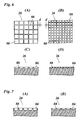
- Fig. 6 (A) shows an enlarged plan view of a pit array 26 formed by square pits 86 that are separated from one another by dam portions 88.
- Fig. 6 (B) shows, on the same scale as Fig. 6 (A) , a plan view of another pit array 26 in which the square pits 86 have a smaller size. However, the width "d" of the dam portions 88 is the same for both pit arrays in Fig. 6 (A) and (B) .
- the dam portions separating the individual pits from one another have the same width for all pit arrays 26.
- Fig. 6 (C) and (D) show cross-sectional views of the pit arrays 26 shown in Fig. 6 (A) and Fig. 6 (B) , respectively. It can be seen here that the pits 86 of both pit arrays have the same depth. Nevertheless, the total pit volume per unit area is smaller for the pit array shown in Fig. 6 (D) , because the dam portions 88 occupy a larger fraction of the surface of the roller. Consequently, the ink layer formed with the pit array shown in Fig. 6 (B) and (D) will be smaller than the thickness of the ink layer formed with the pit array shown in Figs. 6 (A) and (C) .
- Figs. 7 (A) and (B) show cross-sectional views of two pit arrays 26 of an inking roller or inking roller set according to a modified embodiment.
- the pits 86 of both pit arrays have the same footprint but a different depth.
- the width of the dam portions 88 is the same for both pit arrays.
- the total pit volume per unit area is smaller in Fig. 7 (B) because the volume of the individual pits 86 is smaller while the number of pits per unit area is the same as in Fig. 7 (A) .
- Inking rollers with pit arrays of the type described above may be formed for example by engraving the pits into the surface of the inking roller with a laser.
- the shape of the footprint of the pits 86 does not have to be a square but may for example also be a rectangle on a regular hexagon.
- the pits of each pit array 26 are arranged in a regular raster. In any case, the density of the pits should be correlated with the size of the footprints of the pits such that the dam portions 88 have the same width "d" for all pit arrays 26 that belong to the same inking roller or inking roller set.
- the width "d" of the dam portions 88 is selected as small as possible, so that it is just sufficient to reliably separate the individual pits 86 from one another.
- this pit array 26 is used to form an ink layer on the substrate, the ink will be evenly distributed over the surface of the substrate, so that the ink layer will have a uniform thickness.
- the uniformity of the ink layer will be just as good because the dam portions 88 have the same width, and only the layer thickness will be smaller because of the reduced pit volume.
Landscapes
- Inking, Control Or Cleaning Of Printing Machines (AREA)
- Printing Methods (AREA)
Description
- The invention relates to a colour proofing method, wherein an inking roller or a set of inking rollers is used in a colour proofing apparatus for colour proofing by producing ink layers of different thickness.
-
EP 1 876 022 A2DE 10 2007 044 757 A1 each disclose an inking roller which has only a single pit array on its peripheral surface. Within this array, the pits have varying volumes, whereas the dam portions separating the pits all have the same width. -
EP 0 428 893 A2 andEP 1 020 287 A2 - In the printing industry, it is desired to be able to predict a colour value of a printed product or a certain area of the printed product before a print run is started, so that colour errors may be detected and eliminated, e.g. by adjusting the settings of the printing press, changing the recipe of the inks and/or, in the case of flexographic printing, selecting an engraved roller with a different screen.
- It has been known to use a hand-held proofing apparatus having an inking roller for applying an ink film onto a sample of the substrate and then to inspect the colour of the ink film on the substrate.
- Other known proofing methods attempt to simulate the entire flexographic print process by using a colour proofing apparatus that is configured as a miniature version of the printing press.
- In order to produce ink layers of different thickness, it is possible to use a set of inking rollers which have pit arrays with different ink carrying capacities. It is also known to use an inking roller which has a plurality of different pit arrays on its peripheral surface, so that a number of ink layers with different thicknesses can be produced with a single roller.
- Conventionally, the pit arrays are formed by pressing a diamond stamp into the surface layer of the roller, so that the surface material is subject to plastic deformation and a pit is left when the stamp is withdrawn. The volume of the pits and, accordingly, the ink carrying capacity of the inking roller, is controlled by controlling the depth to which the stamp is pressed into the roller surface. The stamp typically has a pyramid shape, so that the footprint of the pit formed in the roller surface increases with increasing depth of the pit. The pit density, i.e. the number of pits per unit area, is typically the same for the different pit arrays, so that the ink carrying capacity, i.e. the total pit volume per unit area, is proportional to the volume of the individual pits, and the width of the dam portions that separate the individual pits from one another increases with decreasing pit volume.
-
EP 2 492 094 A1 - It is an object of the invention to improve the accuracy with which the colour of a printed product to be obtained in a print process, in particular a flexographic print process, can be predicted.
- To that end, the invention proposes colour proofing methods as specified in
claims - Since the width of the dam portions is unchanged, the ink carrying capacity of the pit arrays can be varied only by varying the depth of the pits, without changing the footprint thereof, or by varying both the footprint and the density of the pits. In the latter case, an increased pit density has the effect that the dam portions occupy a larger fraction of the total surface of the roller, so that the ink carrying capacity is reduced.
- The thickness of the dam portions may be relatively small and is determined by the pit array with the largest ink carrying capacity (and the narrowest dams). As a result, the uniformity of the ink layers is improved, especially for pit arrays with small ink carrying capacity. This permits an improved accuracy and reproducibility in the colour measurements to be performed on the ink films, so that the colour impression can be predicted more reliably.
- The pit array of the inking roller that is used for colour proofing does not have to be identical with the pit array of the anilox roller that is actually used for printing. All that is required is that the thickness of the ink layer formed in the actual print process, which ink layer is influenced not only by the screen of the anilox roller but also by the material of the anilox roller, the ink transfer properties of the printing plates, and the like, is equal to the thickness of the ink layer on the proof formed with the inking roller.
- More specific optional features of the invention are indicated in the dependent claims.
- Embodiment examples will now be described in conjunction with the drawings, wherein:
- Fig. 1
- is a schematic cross-sectional view of a colour proofing apparatus;
- Fig. 2
- shows essential parts of the apparatus shown in
Fig. 1 in a top plan view; - Fig. 3
- a schematic view of essential parts of a flexographic printing press;
- Fig. 4
- is a view of an inking roller according to an embodiment of the invention;
- Fig. 5 (A) and (B)
- show two inking rollers of a set according to another embodiment of the invention;
- Fig. 6 (A) - (D)
- are enlarged plan views and cross-sectional views, respectively, of pit arrays of the inking rollers shown in
Fig. 5 ; and - Fig. 7 (A) and (B)
- cross-sectional views of pit arrays of two inking rollers of a set according to another embodiment.
- As is shown in
Fig. 1 , acolour proofing apparatus 10 comprises an engravedinking roller 12, aback pressure cylinder 14, and aconveyor 16 arranged to feed asheet 18 of a print substrate through a nip formed between the inkingroller 12 and theback pressure cylinder 14. - An ink fountain 20 is disposed at the periphery of the
inking roller 12 for inking the surface of the roller. A metered amount of ink may be filled into the ink fountain 20 with apipette 22. The ink fountain 20 further includes aprobe 24 for measuring the temperature and/or the viscosity of the ink contained therein. - As is generally known in the art, the surface of the inking
roller 12 is formed with at least one array of pits which will be filled with ink when they pass through the ink fountain 20. - As is shown in
Fig. 2 , the peripheral surface of theinking roller 12 carries a plurality of screens orpit arrays 26. Thepit arrays 26 extend in axial direction of the inking roller and are equally distributed in circumferential direction. The volume of the pits, and hence the ink carrying capacity of the screens (volume of ink per surface area) differs from array to array. - When the
sheet 18 is fed through the nip between theinking roller 12 and theback pressure cylinder 14, eachpit array 26 will print anink layer 28 onto the print substrate, as has been shown inFig. 2 . The colours of these ink layers (numbered as 1-7 inFig. 2 ) will differ from one another due to the different ink carrying capacities of thepit arrays 26. A colour sensitiveoptical sensor 30, e.g. a spectrometer, is mounted in a stationary position above theconveyor 16 so as to successively measure the colour of eachink layer 28 as thesheet 18 passes through. The colours measured by thesensor 30 will be represented by colour values in a suitable colour space such as CIE XYZ or CIE L*a*b*. - As is shown in
Fig. 1 , thesensor 30 is combined with anillumination system 32 for illuminating the sheet on theconveyor 16. Anotherlight source 34 is mounted below the conveying path of the sheet, so that transparent or translucent sheets may also be illuminated from below. Since the entirecolour proofing apparatus 10 is accommodated in a closedcasing 36 and thesensor 30 and thelight sources ink layers 28 on thesheets 18 will always be measured under the same illumination conditions. - The
conveyor 16 has twoendless conveyor belts 38 passed aroundguide rollers 40 and atensioning roller 42 and spaced apart from one another in axial direction of the inkingroller 12. - A
stationary part 44 of a lower cutting die (Fig. 2 ) is mounted in the space between theconveyor belts 38 on an upstream side of the conveyor. The lower cutting die is supplemented by twomovable parts 46 each of which is fixed on or integrated in one of theconveyor belts 38. Together, theparts rectangular sheet 18 from a larger blank. A corresponding upper cutting die 48 (Fig. 1 ) is pivotally mounted above theconveyor 16. - The cutting mechanism formed by the lower and upper cutting dies can be accessed by an operator by opening a
lid 50 in the top wall of thecasing 36. Thus, a blank of a print substrate may be placed on theconveyor belts 38 and the lower cutting die, and arectangular sheet 18 may be punched out by temporarily closing theupper cutting die 48. Then, the upper cutting die is lifted again and the remaining outer portion of the blank is removed while thecut sheet 18 remains on theparts movable parts 46 of the lower cutting die are configured as sheet holders for holding the marginal areas on both sides of thesheet 18. For example, eachpart 46 of the lower cutting die may be formed with a suction blower and suction nozzles (not shown) for attracting the marginal areas of thesheet 18 and thereby fixing the sheet on theconveyor belts 38. -
Endless guide belts 52 are disposed above theconveyor belts 38 at each end of the inkingroller 12. A lower stretch of each of theseguide belts 52 extends horizontally immediately above theconveyor belt 38, so that, when thesheet 18 is fed through, the marginal areas of the sheet are safely held on the conveyor belts by theguide belts 52. This will prevent the sheet from sticking to the inked peripheral surface of the inkingroller 12. - A
drive motor 54 and a drive gear (shown only schematically inFig. 1 ) are provided for driving the inkingroller 12 and theguide belts 52 in synchronism. Anotherdrive motor 56 is provided for theconveyor 16. The speeds of thedrive motors sheet 18 is conveyed on theconveyor belts 38 exactly equal to the peripheral speed of the inkingroller 12. - The
back pressure cylinder 14 is also driven by thedrive motor 54, and the associated drive train includes a one-way clutch 58 permitting the back pressure cylinder to rotate at a speed that is higher than the speed imposed by thedrive motor 54. The axis of theback pressure cylinder 14 is supported in aset mechanism 60 that is mounted on acarriage 62 and adapted to lift and lower theback pressure cylinder 14 relative to the inkingroller 12. Although not shown in detail, theset mechanism 60 may comprise pneumatic cylinders, eccentrics and the like arranged to lift theback pressure 14 into contact with the inkingroller 12 and thesheet 18 that is passing through and to bias the back pressure cylinder against the inkingroller 12 with a pre-defined force. Since thesheet 18 has been cut to a well-defined width, this force will translate into a well-defined line pressure that will be constant irrespective of the thickness of the sheet. In addition, theback pressure cylinder 14 may have a rubber-elastic surface layer. The body of theback pressure cylinder 14 is preferably formed by a fibre-reinforced carbon, so that theback pressure cylinder 14 has a low weight and a low moment of inertia. - The
carriage 62 is movable back and forth in horizontal direction in parallel with the transport direction of thesheet 18, and carries also acleaning device 64 for the inkingroller 12. By moving thecarriage 62 towards the right side inFig. 1 , thecleaning device 64 may be moved into the position of theback pressure cylinder 14 and into engagement with the lower vertex of the inkingroller 12, so that an automatic cleaning process for cleaning the inking roller may be performed. - The top wall of the
casing 36 has anotherlid 66 or connector giving access to thepipette 22, and yet anotherlid 68 gives access to thesensor 30, so that the sensor may optionally be replaced by another type of optical sensor, e.g. a colour sensor that will also be used in the flexographic printing press, so that the measurement results may directly be compared to one another. - When all the
lids casing 36 are closed, the interior of the casing is sealed air-tightly. Acompressor 70 or any other source of compressed air and avent valve 72 are connected to thecasing 36, so that the interior of the casing may be set under pressure and vented. - With the
colour proofing apparatus 10 as described above, a colour proofing cycle may be performed as will be described below. - It shall be assumed that the proofing process aims at predicting the colour of a print product that is obtained with a flexographic printing press that has schematically been shown in
Fig. 3 . The printing press comprises acentral impression cylinder 74 and a number of colour decks arranged at the periphery of the central impression cylinder. Only one of the colour decks has been shown inFig. 3 . This colour deck comprises aprinting cylinder 76, ananilox roller 78 and achambered doctor blade 80. A web of aprint substrate 82 is passed around thecentral impression cylinder 74 so as to pass through the nip formed with theprinting cylinder 76. Theanilox roller 78 has a pattern of minute ink-receiving pits. The pits of theanilox roller 78 are filled with ink from the chambereddoctor blade 80. Theanilox roller 78 is set against the peripheral surface of theprinting cylinder 76 and rotated, so that the ink is transferred onto theprinting cylinder 76. Theprinting cylinder 76 is rotated and pressed against theprint substrate 82, so that the elevated printing parts of printing plates mounted on theprinting cylinder 76 transfer the ink onto theprint substrate 82, and an image is printed. - The
colour proofing apparatus 10 is used for predicting the colour of that printed image. The screen of theanilox roller 78 corresponds to one of thepit arrays 26 of the inkingroller 12 in the proofing apparatus in the sense that, given the ink transfer properties of theanilox roller 78 and theprinting cylinder 76, the screen of theanilox roller 78 results in an ink layer on thesubstrate 82 which has the same thickness as the ink layer formed on thesheet 18 by means of thepit array 26. - In order to start a proofing cycle, the
vent valve 72 is opened, so that any possible elevated pressure in thecasing 36 is relieved. An operator opens thelid 50 and places a blank of a web material that is identical with the material of theprint substrate 82 onto theconveyor 16 and, more particularly, onto the fixed andmovable parts sheet 18 is cut out of the blank. The upper cutting die 48 is opened again, the remaining parts of the blank are removed, and thelid 50 is closed again. - Using the
pipette 22, a sample of ink which has the same composition as the ink to be used in the chambereddoctor blade 80 is filled into the ink fountain 20. Then, when thecasing 36 is sealed air-tightly, the operator presses a start button of an electronic control unit (not shown) that is connected to theproofing apparatus 10 and controls the further operation thereof as follows: - The
vent valve 72 is closed and thecompressor 70 is activated for raising the air pressure in thecasing 36 to a level at which the evaporation of ink on the inkingroller 12 is reduced to an amount that corresponds to the evaporation losses of ink on theanilox roller 78 and theprinting cylinder 76 of the printing press (Fig. 3 ) when the same operates at its normal printing speed which is much higher than the "printing" speed of theproofing apparatus 10. - The suction blowers (not shown) in the moving
parts 46 of the lower cutting die are activated to suck the marginal areas of thecut sheet 18 and to hold the sheet on themovable parts 46 and hence on theconveyor belts 38. Thedrive motors conveyor 16 and theguide belts 52 as well as the inkingroller 12. Theconveyor belts 38 with the moving cutting dieparts 46 fixed thereon move thesheet 18 towards the inkingroller 12. Theback pressure cylinder 14 is still held in a lowered position in which it is not in contact with the inking roller nor with thesheet 18. Meanwhile, thepit arrays 26 on the inkingroller 12 take up ink from the ink fountain 20 and, as the inking roller rotates, this ink is conveyed along the periphery of the inking roller. Note that, in this phase, evaporation of ink is suppressed by the increased air pressure. The temperature and viscosity of the ink are measured with theprobe 24 and recorded in the control unit. - When the leading edge of the
sheet 18 has passed through between the inkingroller 12 and theback pressure cylinder 14, theset mechanism 60 is activated to lift theback pressure cylinder 14 and bias the same with the pre-defined line pressure against theweb 18. Thedrive motor 54 drives theback pressure cylinder 14 with a circumferential speed that is slightly lower than that of the inkingroller 12. As soon as the back pressure cylinder comes into frictional contact with thesheet 18, the one-way clutch 58 permits the back pressure cylinder to accelerate until the circumferential speed is exactly identical with that of the inkingroller 12, so that no slippage will occur between the rollers and the sheet, regardless of the amount of compression of the rubber-elastic layer of the back pressure cylinder. Thanks to the low moment of inertia of theback pressure cylinder 14, this speed adjustment is achieved within a very short time. - Then, the
pit arrays 26 which have been inked in the ink fountain 20 will successively reach the nip between the inkingroller 12 and theback pressure cylinder 14, and the ink will be transferred onto thesheet 18 to form the ink layers 28 in a well reproducible manner. - Before the trailing edge of the
sheet 18 reaches the nip, theback pressure cylinder 14 is lowered again and brought out of contact with the sheet and the inkingroller 12, so that the back pressure cylinder is prevented from becoming soiled with ink. - Meanwhile, the
guide belts 52 force thesheet 18 to stay on theconveyor belts 38 and prevent the sheet from sticking to the peripheral surface of the inkingroller 12. - The
vent valve 72 is opened so as to relieve the elevated pressure in thecasing 36. - The
sheet 18 reaches the position of thesensor 30 and, while the illumination system is activated, the colours of the ink layers 28 are measured and recorded as the sheet passes through below thestationary sensor 30. The measured colour values are transmitted to the control unit for further processing. - Then, the transport direction of the
conveyor 16 is reversed, so that themovable parts 46 of the lower cutting line, with thesheet 18 still held thereon, are returned to the position shown inFig. 1 . When the sheet has cleared the gap between the inkingroller 12 and theback pressure cylinder 14, thecarriage 62 is moved rightwards inFig. 1 , so that thecleaning unit 64 is brought into its operative position, and the peripheral surface of the inkingroller 12 is cleaned. It should be noted that theconveyor belts 38 pass outside of the axial ends of the inkingroller 12 as is shown inFig. 2 , so that they will not become stained with ink. - Finally, the
lid 50 may be opened and thesheet 18 may be taken out, and a new proofing cycle may begin. - If a proof has to be made for reverse side printing on a transparent print substrate, the
sheet 18 with the ink layers 28 formed on the top side (which will be the reverse side in the actual print process) may be taken out and reversed manually for measuring the colours of the ink layers with thesensor 30 through the transparent sheet. - While
Fig. 2 shows an embodiment where thepit arrays 26 formed on the surface of the inkingroller 12 are configured as stripes that extend in axial direction of the roller,Fig. 4 illustrates an example of an inking roller 12' where thepit arrays 26 are configured as bands that extend in circumferential direction of the roller. -
Fig. 5 (A) and (B) illustrate two inkingrollers single pit array 26 that occupies the entire peripheral surface of the roller. The inkingrollers roller 12 shown inFig. 2 . In the latter case, proofs with different ink layer thicknesses can be formed in a plurality of operating cycles of the colour proofing apparatus. -
Fig. 6 (A) shows an enlarged plan view of apit array 26 formed bysquare pits 86 that are separated from one another bydam portions 88. -
Fig. 6 (B) shows, on the same scale asFig. 6 (A) , a plan view of anotherpit array 26 in which thesquare pits 86 have a smaller size. However, the width "d" of thedam portions 88 is the same for both pit arrays inFig. 6 (A) and (B) . - It is an important feature of the inking
roller 12 shown inFig. 2 that the dam portions separating the individual pits from one another have the same width for allpit arrays 26. The same applies to thepit arrays 26 of the inking roller 12' shown inFig. 4 and also to thepit arrays 26 of the inkingrollers Fig. 5 as well as the pit arrays of all other inking rollers that belong to the same set. -
Fig. 6 (C) and (D) show cross-sectional views of thepit arrays 26 shown inFig. 6 (A) and Fig. 6 (B) , respectively. It can be seen here that thepits 86 of both pit arrays have the same depth. Nevertheless, the total pit volume per unit area is smaller for the pit array shown inFig. 6 (D) , because thedam portions 88 occupy a larger fraction of the surface of the roller. Consequently, the ink layer formed with the pit array shown inFig. 6 (B) and (D) will be smaller than the thickness of the ink layer formed with the pit array shown inFigs. 6 (A) and (C) . -
Figs. 7 (A) and (B) show cross-sectional views of twopit arrays 26 of an inking roller or inking roller set according to a modified embodiment. In this case, thepits 86 of both pit arrays have the same footprint but a different depth. Again, the width of thedam portions 88 is the same for both pit arrays. In this case, the total pit volume per unit area is smaller inFig. 7 (B) because the volume of theindividual pits 86 is smaller while the number of pits per unit area is the same as inFig. 7 (A) . - Inking rollers with pit arrays of the type described above may be formed for example by engraving the pits into the surface of the inking roller with a laser. The shape of the footprint of the
pits 86 does not have to be a square but may for example also be a rectangle on a regular hexagon. Preferably, the pits of eachpit array 26 are arranged in a regular raster. In any case, the density of the pits should be correlated with the size of the footprints of the pits such that thedam portions 88 have the same width "d" for allpit arrays 26 that belong to the same inking roller or inking roller set. - In the
pit array 26 which has the largest total pit volume per surface area, the width "d" of thedam portions 88 is selected as small as possible, so that it is just sufficient to reliably separate theindividual pits 86 from one another. When thispit array 26 is used to form an ink layer on the substrate, the ink will be evenly distributed over the surface of the substrate, so that the ink layer will have a uniform thickness. When an ink layer is formed with another pit array, for which the total pit volume per unit area is smaller, the uniformity of the ink layer will be just as good because thedam portions 88 have the same width, and only the layer thickness will be smaller because of the reduced pit volume.
Claims (4)
- A colour proofing method, wherein an inking roller (12; 12') is used in a colour proofing apparatus for colour proofing by producing ink layers of different thickness, the inking roller having, on its peripheral surface, a plurality of pit arrays (26) formed by pits (86) that are separated from one another by dam portions (88), said pit arrays (26) being different from one another in the total volume of the pits per unit area, wherein the dam portions (88) of different pit arrays (26) have the same width (d).
- The method according to claim 1, wherein the pit arrays (26) are configured as stripes that extend in axial direction of the inking roller.
- The method according to claim 1, wherein the pit arrays (26) are configured as bands that extend in circumferential direction of the roller.
- A colour proofing method, wherein an inking roller set is used in a colour proofing apparatus for colour proofing by producing ink layers of different thickness, the inking roller set, comprising a plurality of inking rollers (82, 84) each of which has, on its peripheral surface, a pit array (26) formed by pits (86) that are separated from one another by dam portions (88), said pit arrays (26) being different from one another in the total volume of pits per unit area, wherein the dam portions (88) of different pit arrays (26) have the same width.
Priority Applications (2)
| Application Number | Priority Date | Filing Date | Title |
|---|---|---|---|
| ES11185341T ES2453917T3 (en) | 2011-10-14 | 2011-10-14 | Inking roller and set of inking rollers for color tests |
| EP20110185341 EP2581227B1 (en) | 2011-10-14 | 2011-10-14 | Inking roller and inking roller set for colour proofing |
Applications Claiming Priority (1)
| Application Number | Priority Date | Filing Date | Title |
|---|---|---|---|
| EP20110185341 EP2581227B1 (en) | 2011-10-14 | 2011-10-14 | Inking roller and inking roller set for colour proofing |
Publications (2)
| Publication Number | Publication Date |
|---|---|
| EP2581227A1 EP2581227A1 (en) | 2013-04-17 |
| EP2581227B1 true EP2581227B1 (en) | 2014-03-19 |
Family
ID=44785702
Family Applications (1)
| Application Number | Title | Priority Date | Filing Date |
|---|---|---|---|
| EP20110185341 Active EP2581227B1 (en) | 2011-10-14 | 2011-10-14 | Inking roller and inking roller set for colour proofing |
Country Status (2)
| Country | Link |
|---|---|
| EP (1) | EP2581227B1 (en) |
| ES (1) | ES2453917T3 (en) |
Families Citing this family (2)
| Publication number | Priority date | Publication date | Assignee | Title |
|---|---|---|---|---|
| JP6764576B2 (en) * | 2018-08-21 | 2020-10-07 | 住友ゴム工業株式会社 | Flexographic printing plate and manufacturing method of liquid crystal display element using it |
| US20210070032A1 (en) | 2019-09-05 | 2021-03-11 | Harper Corporation Of America | Engraved roller for flexographic and gravure printing |
Family Cites Families (4)
| Publication number | Priority date | Publication date | Assignee | Title |
|---|---|---|---|---|
| DE3938449A1 (en) * | 1989-11-18 | 1991-05-23 | Roland Man Druckmasch | PRINT WORK |
| DE19901243A1 (en) * | 1999-01-14 | 2000-07-20 | Heidelberger Druckmasch Ag | Meterable anilox roller in a rotary printing machine |
| DE102006031682A1 (en) * | 2006-07-08 | 2008-01-10 | Man Roland Druckmaschinen Ag | Flexographic printing roller and flexographic printing process |
| DE102007044757A1 (en) * | 2006-10-13 | 2008-04-17 | Heidelberger Druckmaschinen Ag | Screen roller for anilox-printing unit of printing machine, has screen structure comprising slots, where gravure volume of slots at middle section of roller is larger than gravure volume of slots at end section of roller |
-
2011
- 2011-10-14 ES ES11185341T patent/ES2453917T3/en active Active
- 2011-10-14 EP EP20110185341 patent/EP2581227B1/en active Active
Also Published As
| Publication number | Publication date |
|---|---|
| ES2453917T3 (en) | 2014-04-08 |
| EP2581227A1 (en) | 2013-04-17 |
Similar Documents
| Publication | Publication Date | Title |
|---|---|---|
| EP2678160B1 (en) | Colour proofing apparatus and method | |
| CN103987524B (en) | Adjustment method and device for printing machine | |
| EP1466754B1 (en) | Coating material applying method and coating material applying apparatus for applying a coating material to surfaces of prints, and a printing machine having the coating material applying apparatus | |
| JP2848912B2 (en) | How to run the press during the adjustment phase before the start of production | |
| US5195435A (en) | Continuous intaglio printing apparatus and method | |
| JP2007536128A5 (en) | ||
| TWI396627B (en) | Calibration method in a machine for processing plate elements | |
| US6422143B1 (en) | Flexographic preview printer | |
| US5448949A (en) | Method and device for adjusting a contact pressure between ink-carrying cylinders of a printing machine | |
| EP2581227A1 (en) | Inking roller and inking roller set for colour proofing | |
| US8746143B2 (en) | Method and apparatus for compensating for inking differences in printing presses with an anilox short inking unit and printing press having the apparatus | |
| US4522057A (en) | Printing ink proofer | |
| US20080295723A1 (en) | Printing press | |
| EP0867281A1 (en) | Method and device for detecting and controlling the printing pressure in flexographic machines | |
| US20060162592A1 (en) | Gravure printing unit for printing a printing material web in a printing press | |
| EP0109725B1 (en) | Improved printing ink proofer | |
| EP1527875B1 (en) | Dampening water feeding method and printing machine | |
| JP7784025B2 (en) | Sheet processing machine with cooling roller and inspection device, and sheet printing machine with a simultan double printing unit, a hardening device and a cooling device | |
| US6289811B1 (en) | Method and apparatus for sampling and inspecting ink for a printing press | |
| SU441174A1 (en) | Proofing apparatus | |
| CN103252977B (en) | For being carried out the forme of hectographic printing by means of moistening medium | |
| GB2151988A (en) | Apparatus for proof printing or for sample coating | |
| JP2011527419A (en) | Printer | |
| KR100727042B1 (en) | Multifunction Printing Unit | |
| KR100700226B1 (en) | Apparatus and method for printing on tablet type object such as medical tablet |
Legal Events
| Date | Code | Title | Description |
|---|---|---|---|
| PUAI | Public reference made under article 153(3) epc to a published international application that has entered the european phase |
Free format text: ORIGINAL CODE: 0009012 |
|
| AK | Designated contracting states |
Kind code of ref document: A1 Designated state(s): AL AT BE BG CH CY CZ DE DK EE ES FI FR GB GR HR HU IE IS IT LI LT LU LV MC MK MT NL NO PL PT RO RS SE SI SK SM TR |
|
| AX | Request for extension of the european patent |
Extension state: BA ME |
|
| 17P | Request for examination filed |
Effective date: 20131014 |
|
| RBV | Designated contracting states (corrected) |
Designated state(s): AL AT BE BG CH CY CZ DE DK EE ES FI FR GB GR HR HU IE IS IT LI LT LU LV MC MK MT NL NO PL PT RO RS SE SI SK SM TR |
|
| GRAP | Despatch of communication of intention to grant a patent |
Free format text: ORIGINAL CODE: EPIDOSNIGR1 |
|
| INTG | Intention to grant announced |
Effective date: 20131212 |
|
| GRAS | Grant fee paid |
Free format text: ORIGINAL CODE: EPIDOSNIGR3 |
|
| GRAA | (expected) grant |
Free format text: ORIGINAL CODE: 0009210 |
|
| AK | Designated contracting states |
Kind code of ref document: B1 Designated state(s): AL AT BE BG CH CY CZ DE DK EE ES FI FR GB GR HR HU IE IS IT LI LT LU LV MC MK MT NL NO PL PT RO RS SE SI SK SM TR |
|
| REG | Reference to a national code |
Ref country code: GB Ref legal event code: FG4D |
|
| REG | Reference to a national code |
Ref country code: CH Ref legal event code: EP |
|
| REG | Reference to a national code |
Ref country code: ES Ref legal event code: FG2A Ref document number: 2453917 Country of ref document: ES Kind code of ref document: T3 Effective date: 20140408 |
|
| REG | Reference to a national code |
Ref country code: AT Ref legal event code: REF Ref document number: 657391 Country of ref document: AT Kind code of ref document: T Effective date: 20140415 |
|
| REG | Reference to a national code |
Ref country code: IE Ref legal event code: FG4D |
|
| REG | Reference to a national code |
Ref country code: DE Ref legal event code: R096 Ref document number: 602011005459 Country of ref document: DE Effective date: 20140430 |
|
| PG25 | Lapsed in a contracting state [announced via postgrant information from national office to epo] |
Ref country code: NO Free format text: LAPSE BECAUSE OF FAILURE TO SUBMIT A TRANSLATION OF THE DESCRIPTION OR TO PAY THE FEE WITHIN THE PRESCRIBED TIME-LIMIT Effective date: 20140619 Ref country code: LT Free format text: LAPSE BECAUSE OF FAILURE TO SUBMIT A TRANSLATION OF THE DESCRIPTION OR TO PAY THE FEE WITHIN THE PRESCRIBED TIME-LIMIT Effective date: 20140319 |
|
| REG | Reference to a national code |
Ref country code: NL Ref legal event code: VDEP Effective date: 20140319 |
|
| REG | Reference to a national code |
Ref country code: AT Ref legal event code: MK05 Ref document number: 657391 Country of ref document: AT Kind code of ref document: T Effective date: 20140319 |
|
| REG | Reference to a national code |
Ref country code: LT Ref legal event code: MG4D |
|
| PG25 | Lapsed in a contracting state [announced via postgrant information from national office to epo] |
Ref country code: FI Free format text: LAPSE BECAUSE OF FAILURE TO SUBMIT A TRANSLATION OF THE DESCRIPTION OR TO PAY THE FEE WITHIN THE PRESCRIBED TIME-LIMIT Effective date: 20140319 Ref country code: CY Free format text: LAPSE BECAUSE OF FAILURE TO SUBMIT A TRANSLATION OF THE DESCRIPTION OR TO PAY THE FEE WITHIN THE PRESCRIBED TIME-LIMIT Effective date: 20140319 Ref country code: SE Free format text: LAPSE BECAUSE OF FAILURE TO SUBMIT A TRANSLATION OF THE DESCRIPTION OR TO PAY THE FEE WITHIN THE PRESCRIBED TIME-LIMIT Effective date: 20140319 |
|
| PG25 | Lapsed in a contracting state [announced via postgrant information from national office to epo] |
Ref country code: HR Free format text: LAPSE BECAUSE OF FAILURE TO SUBMIT A TRANSLATION OF THE DESCRIPTION OR TO PAY THE FEE WITHIN THE PRESCRIBED TIME-LIMIT Effective date: 20140319 Ref country code: LV Free format text: LAPSE BECAUSE OF FAILURE TO SUBMIT A TRANSLATION OF THE DESCRIPTION OR TO PAY THE FEE WITHIN THE PRESCRIBED TIME-LIMIT Effective date: 20140319 Ref country code: RS Free format text: LAPSE BECAUSE OF FAILURE TO SUBMIT A TRANSLATION OF THE DESCRIPTION OR TO PAY THE FEE WITHIN THE PRESCRIBED TIME-LIMIT Effective date: 20140319 |
|
| PG25 | Lapsed in a contracting state [announced via postgrant information from national office to epo] |
Ref country code: CZ Free format text: LAPSE BECAUSE OF FAILURE TO SUBMIT A TRANSLATION OF THE DESCRIPTION OR TO PAY THE FEE WITHIN THE PRESCRIBED TIME-LIMIT Effective date: 20140319 Ref country code: NL Free format text: LAPSE BECAUSE OF FAILURE TO SUBMIT A TRANSLATION OF THE DESCRIPTION OR TO PAY THE FEE WITHIN THE PRESCRIBED TIME-LIMIT Effective date: 20140319 Ref country code: IS Free format text: LAPSE BECAUSE OF FAILURE TO SUBMIT A TRANSLATION OF THE DESCRIPTION OR TO PAY THE FEE WITHIN THE PRESCRIBED TIME-LIMIT Effective date: 20140719 Ref country code: BE Free format text: LAPSE BECAUSE OF FAILURE TO SUBMIT A TRANSLATION OF THE DESCRIPTION OR TO PAY THE FEE WITHIN THE PRESCRIBED TIME-LIMIT Effective date: 20140319 Ref country code: BG Free format text: LAPSE BECAUSE OF FAILURE TO SUBMIT A TRANSLATION OF THE DESCRIPTION OR TO PAY THE FEE WITHIN THE PRESCRIBED TIME-LIMIT Effective date: 20140619 Ref country code: EE Free format text: LAPSE BECAUSE OF FAILURE TO SUBMIT A TRANSLATION OF THE DESCRIPTION OR TO PAY THE FEE WITHIN THE PRESCRIBED TIME-LIMIT Effective date: 20140319 Ref country code: RO Free format text: LAPSE BECAUSE OF FAILURE TO SUBMIT A TRANSLATION OF THE DESCRIPTION OR TO PAY THE FEE WITHIN THE PRESCRIBED TIME-LIMIT Effective date: 20140319 |
|
| PG25 | Lapsed in a contracting state [announced via postgrant information from national office to epo] |
Ref country code: AT Free format text: LAPSE BECAUSE OF FAILURE TO SUBMIT A TRANSLATION OF THE DESCRIPTION OR TO PAY THE FEE WITHIN THE PRESCRIBED TIME-LIMIT Effective date: 20140319 Ref country code: SK Free format text: LAPSE BECAUSE OF FAILURE TO SUBMIT A TRANSLATION OF THE DESCRIPTION OR TO PAY THE FEE WITHIN THE PRESCRIBED TIME-LIMIT Effective date: 20140319 Ref country code: PL Free format text: LAPSE BECAUSE OF FAILURE TO SUBMIT A TRANSLATION OF THE DESCRIPTION OR TO PAY THE FEE WITHIN THE PRESCRIBED TIME-LIMIT Effective date: 20140319 |
|
| REG | Reference to a national code |
Ref country code: DE Ref legal event code: R097 Ref document number: 602011005459 Country of ref document: DE |
|
| PG25 | Lapsed in a contracting state [announced via postgrant information from national office to epo] |
Ref country code: PT Free format text: LAPSE BECAUSE OF FAILURE TO SUBMIT A TRANSLATION OF THE DESCRIPTION OR TO PAY THE FEE WITHIN THE PRESCRIBED TIME-LIMIT Effective date: 20140721 |
|
| PLBE | No opposition filed within time limit |
Free format text: ORIGINAL CODE: 0009261 |
|
| STAA | Information on the status of an ep patent application or granted ep patent |
Free format text: STATUS: NO OPPOSITION FILED WITHIN TIME LIMIT |
|
| PG25 | Lapsed in a contracting state [announced via postgrant information from national office to epo] |
Ref country code: DK Free format text: LAPSE BECAUSE OF FAILURE TO SUBMIT A TRANSLATION OF THE DESCRIPTION OR TO PAY THE FEE WITHIN THE PRESCRIBED TIME-LIMIT Effective date: 20140319 |
|
| 26N | No opposition filed |
Effective date: 20141222 |
|
| REG | Reference to a national code |
Ref country code: DE Ref legal event code: R097 Ref document number: 602011005459 Country of ref document: DE Effective date: 20141222 |
|
| PG25 | Lapsed in a contracting state [announced via postgrant information from national office to epo] |
Ref country code: LU Free format text: LAPSE BECAUSE OF FAILURE TO SUBMIT A TRANSLATION OF THE DESCRIPTION OR TO PAY THE FEE WITHIN THE PRESCRIBED TIME-LIMIT Effective date: 20141014 Ref country code: MC Free format text: LAPSE BECAUSE OF FAILURE TO SUBMIT A TRANSLATION OF THE DESCRIPTION OR TO PAY THE FEE WITHIN THE PRESCRIBED TIME-LIMIT Effective date: 20140319 |
|
| REG | Reference to a national code |
Ref country code: CH Ref legal event code: PL |
|
| REG | Reference to a national code |
Ref country code: IE Ref legal event code: MM4A |
|
| PG25 | Lapsed in a contracting state [announced via postgrant information from national office to epo] |
Ref country code: LI Free format text: LAPSE BECAUSE OF NON-PAYMENT OF DUE FEES Effective date: 20141031 Ref country code: SI Free format text: LAPSE BECAUSE OF FAILURE TO SUBMIT A TRANSLATION OF THE DESCRIPTION OR TO PAY THE FEE WITHIN THE PRESCRIBED TIME-LIMIT Effective date: 20140319 Ref country code: CH Free format text: LAPSE BECAUSE OF NON-PAYMENT OF DUE FEES Effective date: 20141031 |
|
| REG | Reference to a national code |
Ref country code: FR Ref legal event code: ST Effective date: 20150630 |
|
| PG25 | Lapsed in a contracting state [announced via postgrant information from national office to epo] |
Ref country code: FR Free format text: LAPSE BECAUSE OF NON-PAYMENT OF DUE FEES Effective date: 20141031 |
|
| PG25 | Lapsed in a contracting state [announced via postgrant information from national office to epo] |
Ref country code: IE Free format text: LAPSE BECAUSE OF NON-PAYMENT OF DUE FEES Effective date: 20141014 |
|
| PG25 | Lapsed in a contracting state [announced via postgrant information from national office to epo] |
Ref country code: SM Free format text: LAPSE BECAUSE OF FAILURE TO SUBMIT A TRANSLATION OF THE DESCRIPTION OR TO PAY THE FEE WITHIN THE PRESCRIBED TIME-LIMIT Effective date: 20140319 |
|
| GBPC | Gb: european patent ceased through non-payment of renewal fee |
Effective date: 20151014 |
|
| PG25 | Lapsed in a contracting state [announced via postgrant information from national office to epo] |
Ref country code: GR Free format text: LAPSE BECAUSE OF FAILURE TO SUBMIT A TRANSLATION OF THE DESCRIPTION OR TO PAY THE FEE WITHIN THE PRESCRIBED TIME-LIMIT Effective date: 20140620 |
|
| PG25 | Lapsed in a contracting state [announced via postgrant information from national office to epo] |
Ref country code: HU Free format text: LAPSE BECAUSE OF FAILURE TO SUBMIT A TRANSLATION OF THE DESCRIPTION OR TO PAY THE FEE WITHIN THE PRESCRIBED TIME-LIMIT; INVALID AB INITIO Effective date: 20111014 Ref country code: TR Free format text: LAPSE BECAUSE OF FAILURE TO SUBMIT A TRANSLATION OF THE DESCRIPTION OR TO PAY THE FEE WITHIN THE PRESCRIBED TIME-LIMIT Effective date: 20140319 Ref country code: GB Free format text: LAPSE BECAUSE OF NON-PAYMENT OF DUE FEES Effective date: 20151014 Ref country code: MT Free format text: LAPSE BECAUSE OF FAILURE TO SUBMIT A TRANSLATION OF THE DESCRIPTION OR TO PAY THE FEE WITHIN THE PRESCRIBED TIME-LIMIT Effective date: 20140319 |
|
| REG | Reference to a national code |
Ref country code: DE Ref legal event code: R082 Ref document number: 602011005459 Country of ref document: DE |
|
| PG25 | Lapsed in a contracting state [announced via postgrant information from national office to epo] |
Ref country code: MK Free format text: LAPSE BECAUSE OF FAILURE TO SUBMIT A TRANSLATION OF THE DESCRIPTION OR TO PAY THE FEE WITHIN THE PRESCRIBED TIME-LIMIT Effective date: 20140319 |
|
| PG25 | Lapsed in a contracting state [announced via postgrant information from national office to epo] |
Ref country code: AL Free format text: LAPSE BECAUSE OF FAILURE TO SUBMIT A TRANSLATION OF THE DESCRIPTION OR TO PAY THE FEE WITHIN THE PRESCRIBED TIME-LIMIT Effective date: 20140319 |
|
| P01 | Opt-out of the competence of the unified patent court (upc) registered |
Effective date: 20230519 |
|
| PGFP | Annual fee paid to national office [announced via postgrant information from national office to epo] |
Ref country code: DE Payment date: 20251021 Year of fee payment: 15 |
|
| PGFP | Annual fee paid to national office [announced via postgrant information from national office to epo] |
Ref country code: IT Payment date: 20251024 Year of fee payment: 15 |
|
| PGFP | Annual fee paid to national office [announced via postgrant information from national office to epo] |
Ref country code: ES Payment date: 20251210 Year of fee payment: 15 |