EP2581038A1 - Appareil auditif automatique en temps réel basé sur des potentiels auditifs évoqués - Google Patents
Appareil auditif automatique en temps réel basé sur des potentiels auditifs évoqués Download PDFInfo
- Publication number
- EP2581038A1 EP2581038A1 EP11185225.7A EP11185225A EP2581038A1 EP 2581038 A1 EP2581038 A1 EP 2581038A1 EP 11185225 A EP11185225 A EP 11185225A EP 2581038 A1 EP2581038 A1 EP 2581038A1
- Authority
- EP
- European Patent Office
- Prior art keywords
- signal
- hearing aid
- user
- hearing
- electric
- Prior art date
- Legal status (The legal status is an assumption and is not a legal conclusion. Google has not performed a legal analysis and makes no representation as to the accuracy of the status listed.)
- Granted
Links
- 230000000763 evoking effect Effects 0.000 title claims abstract description 23
- 238000012545 processing Methods 0.000 claims abstract description 63
- 210000004556 brain Anatomy 0.000 claims abstract description 57
- 238000012360 testing method Methods 0.000 claims abstract description 48
- 238000000034 method Methods 0.000 claims abstract description 46
- 230000001419 dependent effect Effects 0.000 claims abstract description 24
- 230000008569 process Effects 0.000 claims abstract description 15
- 238000005259 measurement Methods 0.000 claims abstract description 12
- 230000004044 response Effects 0.000 claims description 51
- 210000000133 brain stem Anatomy 0.000 claims description 17
- 210000000613 ear canal Anatomy 0.000 claims description 14
- 238000004422 calculation algorithm Methods 0.000 claims description 12
- 230000008859 change Effects 0.000 claims description 8
- 238000004891 communication Methods 0.000 claims description 8
- 230000005236 sound signal Effects 0.000 abstract description 28
- 230000008901 benefit Effects 0.000 abstract description 7
- 238000012544 monitoring process Methods 0.000 abstract description 4
- 238000011156 evaluation Methods 0.000 abstract description 2
- 238000004458 analytical method Methods 0.000 description 11
- 238000006243 chemical reaction Methods 0.000 description 9
- 230000001939 inductive effect Effects 0.000 description 9
- 230000006870 function Effects 0.000 description 8
- 230000001149 cognitive effect Effects 0.000 description 7
- 238000012935 Averaging Methods 0.000 description 5
- 230000006978 adaptation Effects 0.000 description 5
- 230000003321 amplification Effects 0.000 description 5
- 230000005540 biological transmission Effects 0.000 description 5
- 230000002354 daily effect Effects 0.000 description 5
- 230000006866 deterioration Effects 0.000 description 5
- 230000000694 effects Effects 0.000 description 5
- 210000003128 head Anatomy 0.000 description 5
- 238000003199 nucleic acid amplification method Methods 0.000 description 5
- 208000016354 hearing loss disease Diseases 0.000 description 4
- 206010011878 Deafness Diseases 0.000 description 3
- 230000015572 biosynthetic process Effects 0.000 description 3
- 230000007177 brain activity Effects 0.000 description 3
- 238000004590 computer program Methods 0.000 description 3
- 230000008878 coupling Effects 0.000 description 3
- 238000010168 coupling process Methods 0.000 description 3
- 238000005859 coupling reaction Methods 0.000 description 3
- 230000010370 hearing loss Effects 0.000 description 3
- 231100000888 hearing loss Toxicity 0.000 description 3
- 230000007774 longterm Effects 0.000 description 3
- 230000000873 masking effect Effects 0.000 description 3
- 238000005070 sampling Methods 0.000 description 3
- 210000004761 scalp Anatomy 0.000 description 3
- 210000003625 skull Anatomy 0.000 description 3
- 238000003786 synthesis reaction Methods 0.000 description 3
- 238000012546 transfer Methods 0.000 description 3
- 230000004913 activation Effects 0.000 description 2
- 230000003542 behavioural effect Effects 0.000 description 2
- 230000006835 compression Effects 0.000 description 2
- 238000007906 compression Methods 0.000 description 2
- 210000005069 ears Anatomy 0.000 description 2
- 238000000537 electroencephalography Methods 0.000 description 2
- 238000001914 filtration Methods 0.000 description 2
- 230000001965 increasing effect Effects 0.000 description 2
- 230000001537 neural effect Effects 0.000 description 2
- 230000000737 periodic effect Effects 0.000 description 2
- 230000035945 sensitivity Effects 0.000 description 2
- 230000002459 sustained effect Effects 0.000 description 2
- 230000002123 temporal effect Effects 0.000 description 2
- 208000032041 Hearing impaired Diseases 0.000 description 1
- 230000002457 bidirectional effect Effects 0.000 description 1
- 238000004364 calculation method Methods 0.000 description 1
- 230000001413 cellular effect Effects 0.000 description 1
- 238000012937 correction Methods 0.000 description 1
- 230000009849 deactivation Effects 0.000 description 1
- 238000013461 design Methods 0.000 description 1
- 238000003748 differential diagnosis Methods 0.000 description 1
- 230000005672 electromagnetic field Effects 0.000 description 1
- 230000005670 electromagnetic radiation Effects 0.000 description 1
- 230000007613 environmental effect Effects 0.000 description 1
- 230000003203 everyday effect Effects 0.000 description 1
- 238000001746 injection moulding Methods 0.000 description 1
- 238000003698 laser cutting Methods 0.000 description 1
- 239000000463 material Substances 0.000 description 1
- 230000003340 mental effect Effects 0.000 description 1
- 230000006996 mental state Effects 0.000 description 1
- 238000012986 modification Methods 0.000 description 1
- 230000004048 modification Effects 0.000 description 1
- 238000012806 monitoring device Methods 0.000 description 1
- 238000005192 partition Methods 0.000 description 1
- 230000010363 phase shift Effects 0.000 description 1
- 230000009467 reduction Effects 0.000 description 1
- 230000011514 reflex Effects 0.000 description 1
- 230000000284 resting effect Effects 0.000 description 1
- 230000035807 sensation Effects 0.000 description 1
- 230000001953 sensory effect Effects 0.000 description 1
- 230000008054 signal transmission Effects 0.000 description 1
- 239000007787 solid Substances 0.000 description 1
- 230000001629 suppression Effects 0.000 description 1
- 230000009885 systemic effect Effects 0.000 description 1
- 210000001519 tissue Anatomy 0.000 description 1
- 230000009466 transformation Effects 0.000 description 1
- 238000012795 verification Methods 0.000 description 1
- 230000000007 visual effect Effects 0.000 description 1
Images


Classifications
-
- H—ELECTRICITY
- H04—ELECTRIC COMMUNICATION TECHNIQUE
- H04R—LOUDSPEAKERS, MICROPHONES, GRAMOPHONE PICK-UPS OR LIKE ACOUSTIC ELECTROMECHANICAL TRANSDUCERS; DEAF-AID SETS; PUBLIC ADDRESS SYSTEMS
- H04R25/00—Deaf-aid sets, i.e. electro-acoustic or electro-mechanical hearing aids; Electric tinnitus maskers providing an auditory perception
- H04R25/30—Monitoring or testing of hearing aids, e.g. functioning, settings, battery power
-
- H—ELECTRICITY
- H04—ELECTRIC COMMUNICATION TECHNIQUE
- H04R—LOUDSPEAKERS, MICROPHONES, GRAMOPHONE PICK-UPS OR LIKE ACOUSTIC ELECTROMECHANICAL TRANSDUCERS; DEAF-AID SETS; PUBLIC ADDRESS SYSTEMS
- H04R25/00—Deaf-aid sets, i.e. electro-acoustic or electro-mechanical hearing aids; Electric tinnitus maskers providing an auditory perception
- H04R25/70—Adaptation of deaf aid to hearing loss, e.g. initial electronic fitting
-
- A—HUMAN NECESSITIES
- A61—MEDICAL OR VETERINARY SCIENCE; HYGIENE
- A61B—DIAGNOSIS; SURGERY; IDENTIFICATION
- A61B5/00—Measuring for diagnostic purposes; Identification of persons
- A61B5/12—Audiometering
- A61B5/121—Audiometering evaluating hearing capacity
-
- A—HUMAN NECESSITIES
- A61—MEDICAL OR VETERINARY SCIENCE; HYGIENE
- A61B—DIAGNOSIS; SURGERY; IDENTIFICATION
- A61B5/00—Measuring for diagnostic purposes; Identification of persons
- A61B5/24—Detecting, measuring or recording bioelectric or biomagnetic signals of the body or parts thereof
- A61B5/316—Modalities, i.e. specific diagnostic methods
- A61B5/369—Electroencephalography [EEG]
- A61B5/377—Electroencephalography [EEG] using evoked responses
- A61B5/38—Acoustic or auditory stimuli
-
- A—HUMAN NECESSITIES
- A61—MEDICAL OR VETERINARY SCIENCE; HYGIENE
- A61B—DIAGNOSIS; SURGERY; IDENTIFICATION
- A61B5/00—Measuring for diagnostic purposes; Identification of persons
- A61B5/68—Arrangements of detecting, measuring or recording means, e.g. sensors, in relation to patient
- A61B5/6801—Arrangements of detecting, measuring or recording means, e.g. sensors, in relation to patient specially adapted to be attached to or worn on the body surface
- A61B5/6813—Specially adapted to be attached to a specific body part
- A61B5/6814—Head
- A61B5/6815—Ear
-
- G—PHYSICS
- G06—COMPUTING; CALCULATING OR COUNTING
- G06F—ELECTRIC DIGITAL DATA PROCESSING
- G06F3/00—Input arrangements for transferring data to be processed into a form capable of being handled by the computer; Output arrangements for transferring data from processing unit to output unit, e.g. interface arrangements
- G06F3/01—Input arrangements or combined input and output arrangements for interaction between user and computer
- G06F3/011—Arrangements for interaction with the human body, e.g. for user immersion in virtual reality
- G06F3/015—Input arrangements based on nervous system activity detection, e.g. brain waves [EEG] detection, electromyograms [EMG] detection, electrodermal response detection
-
- H—ELECTRICITY
- H04—ELECTRIC COMMUNICATION TECHNIQUE
- H04R—LOUDSPEAKERS, MICROPHONES, GRAMOPHONE PICK-UPS OR LIKE ACOUSTIC ELECTROMECHANICAL TRANSDUCERS; DEAF-AID SETS; PUBLIC ADDRESS SYSTEMS
- H04R25/00—Deaf-aid sets, i.e. electro-acoustic or electro-mechanical hearing aids; Electric tinnitus maskers providing an auditory perception
- H04R25/55—Deaf-aid sets, i.e. electro-acoustic or electro-mechanical hearing aids; Electric tinnitus maskers providing an auditory perception using an external connection, either wireless or wired
- H04R25/552—Binaural
-
- H—ELECTRICITY
- H04—ELECTRIC COMMUNICATION TECHNIQUE
- H04R—LOUDSPEAKERS, MICROPHONES, GRAMOPHONE PICK-UPS OR LIKE ACOUSTIC ELECTROMECHANICAL TRANSDUCERS; DEAF-AID SETS; PUBLIC ADDRESS SYSTEMS
- H04R25/00—Deaf-aid sets, i.e. electro-acoustic or electro-mechanical hearing aids; Electric tinnitus maskers providing an auditory perception
- H04R25/55—Deaf-aid sets, i.e. electro-acoustic or electro-mechanical hearing aids; Electric tinnitus maskers providing an auditory perception using an external connection, either wireless or wired
- H04R25/554—Deaf-aid sets, i.e. electro-acoustic or electro-mechanical hearing aids; Electric tinnitus maskers providing an auditory perception using an external connection, either wireless or wired using a wireless connection, e.g. between microphone and amplifier or using Tcoils
-
- H—ELECTRICITY
- H04—ELECTRIC COMMUNICATION TECHNIQUE
- H04R—LOUDSPEAKERS, MICROPHONES, GRAMOPHONE PICK-UPS OR LIKE ACOUSTIC ELECTROMECHANICAL TRANSDUCERS; DEAF-AID SETS; PUBLIC ADDRESS SYSTEMS
- H04R25/00—Deaf-aid sets, i.e. electro-acoustic or electro-mechanical hearing aids; Electric tinnitus maskers providing an auditory perception
- H04R25/55—Deaf-aid sets, i.e. electro-acoustic or electro-mechanical hearing aids; Electric tinnitus maskers providing an auditory perception using an external connection, either wireless or wired
- H04R25/558—Remote control, e.g. of amplification, frequency
Definitions
- the present application relates to hearing aids, and to the monitoring of auditory evoked potentials (AEP).
- AEP auditory evoked potentials
- the disclosure relates specifically to a hearing aid comprising means for picking up and analysing auditory evoked potentials, e.g. an auditory brainstem response (ABR).
- ABR auditory brainstem response
- the application furthermore relates to a method of operating a hearing aid and to the use of a hearing aid.
- the application further relates to a data processing system comprising a processor and program code means for causing the processor to perform at least some of the steps of the method.
- the disclosure may e.g. be useful in hearing aids or hearing aid systems where a continuous evaluation of a user's hearing thresholds is needed.
- Fitting of a hearing aid to a particular person's hearing impairment generally requires knowledge of clinically measured hearing thresholds for the person in question.
- the auditory brainstem response can be used as an objective estimate of audiometric hearing thresholds (e.g. [S.zebecher et al., 2006]).
- Future hearing aids may include electrodes on the surface of the hearing aid shell facing the ear canal to record electric brain wave signals such as an electroencephalogram (EEG) (cf. e.g. [Lunner, 2010]).
- EEG electroencephalogram
- a portable EEG monitoring apparatus is described in [Kidmose and Westermann, 2010].
- a hearing aid comprising electrodes for detecting electrical signals such as brain waves is described in [Kidmose and Mandic, 2011].
- the design of stimuli for a system for the recordal of an auditory brainstem response (ABR) of a person is e.g. described in WO 2006/003172 A1 .
- Auditory evoked potentials are a subclass of event-related potentials (ERP)s, such as auditory brainstem response (ABR).
- ERPs are brain responses that are time-locked to some "event", such as a sensory stimulus, a mental event (such as recognition of a target stimulus), or the omission of a stimulus.
- the "event” is a sound.
- AEPs (and ERPs) are very small electrical voltage potentials originating from the brain recorded from the scalp in response to an auditory stimulus, such as different tones, speech sounds, etc.
- the analysis of measured AEPs for a person can be used to estimate audiometric hearing thresholds (HTL) of that person.
- a fitting algorithm can be executed in the hearing aid using the estimated hearing thresholds as inputs to determine an appropriate frequency dependent gain for the user wearing the hearing aid.
- auditory test signals e.g. chirps, clicks, or narrowband signals such as tones making auditory steady state response, ASSR
- ASSR auditory steady state response
- auditory models it s further proposed to use auditory models to continuously being able to present an auditory test signal that does not disturb the user of the hearing aid.
- the auditory test signals are thus presented through the hearing aid under daily life use in a way that the test signals are partly or fully inaudible (via e.g. a loudness masking model).
- the point is that through the hearing aid in daily use, extremely many test signals may be presented since measuring time is not really an issue compared to a clinical AEP (e.g. ABR) testing situation, and therefore an accurate estimation of the AEP response can be obtained.
- ABR clinical AEP
- the AEP test signal and the environmental signal can be, at least to a first approximation, seen as independent signals, and therefore will long term averaging of the recorded electric brain waves make a good estimate of an AEP and hence make an estimate of the acoustic hearing thresholds. Thereby no clinically measured hearing thresholds are required, since the hearing thresholds are estimated from the auditory brain response.
- An object of the present application is to provide a hearing aid capable of monitoring a user's hearing ability over time.
- a hearing aid is a hearing aid
- the hearing aid comprises at least two electrodes. In an embodiment, the hearing aid comprises a reference electrode.
- the electric test signal is adapted to provide that the auditory test stimulus is masked and/or inaudible to the user.
- Such adaptation may e.g. be based on a model of the human auditory system, e.g. a loudness masking model.
- Psycho-acoustic models of the human auditory system are e.g. discussed in [Fastl & Zwicker, 2007], cf. e.g. chapter 4 on 'Masking', pages 61-110 , and chapter 7.5 on 'Models for Just-Noticeable Variations', pages 194-202 .
- An advantage thereof is that when the auditory test stimuli are partly or fully masked they will not compromise the normal daily use of the hearing aid.
- the signal processor is adapted to estimate the user's hearing thresholds based on said processed brain signals. This has the advantage that the hearing aid can be fully or partially self fitting.
- the auditory evoked potential is an auditory brainstem response.
- the auditory brainstem response is an auditory evoked potential extracted from ongoing electrical activity in the brain and recorded via electrodes placed on the scalp.
- AEP and ABR are e.g. described in Wikipedia [Wiki-AEP] and [Wiki-ABR], respectively.
- the auditory evoked potential is an auditory steady state response.
- Auditory Steady State Response is an auditory evoked potential, elicited with modulated tones that can be used to predict hearing sensitivity in patients of all ages. It is an electrophysiologic response to rapid auditory stimuli and creates a statistically valid estimated audiogram (evoked potential used to predict hearing thresholds for normal hearing individuals and those with hearing loss).
- the ASSR uses statistical measures to determine if and when a threshold is present and is a "cross-check" for verification purposes prior to arriving at a differential diagnosis [Wiki-ABR] (see e.g. US 7,035,745 or [Stzebecher et al., 2006]).
- a frequency specific hearing threshold level (HTL) estimate can be provided through ASSR.
- HTL frequency specific hearing threshold level
- the frequency specific ASSR response provides an estimate of the hearing sensitivity as a function of frequency.
- these HTLs can then be used to apply conventional hearing threshold based prescription rules.
- the signal processor is adapted to run a fitting algorithm, such as NAL-RP, NAL-NL2 (National Acoustic Laboratories, Australia), DSL (National Centre for Audiology, Ontario, Canada), ASA (American Seniors Association), VAC (Veterans Affairs Canada), etc. using said estimated hearing thresholds.
- the fitting algorithm uses the estimated hearing thresholds to determine the appropriate frequency dependent gain for the user.
- the hearing aid is adapted to execute the fitting algorithm in real-time.
- the hearing aid is adapted to execute the fitting algorithm automatically.
- ABR thresholds can be used for hearing aid fittings.
- New fitting formulas such as DSL v5.0 allow the user to base the settings in the hearing aid on the ABR thresholds. Correction factors do exist for converting ABR thresholds to behavioral thresholds.
- the Desired Sensation Level multistage input/output algorithm (DSLm[i/o]) is an electroacoustic fitting algorithm particularly aimed at children (National Centre for Audiology, Ontario, Canada).
- the hearing aid records the AEP, e.g. ASSR, response during daily use for some time (e.g. a few days, e.g. at least 3-5 days) (without amplification or just minor amplification) the estimate of the ASSR response is accurate and the hearing aid can use the given prescription rule (NAL, DSL, etc.) to provide an individually prescribed amplification scheme (without having to measure and enter a clinically obtained audiogram).
- AEP e.g. ASSR
- AEP measurements may further be used to measure supra-threshold effects.
- Supra-threshold AEPs can help to determine whether the signal processing applied in a hearing aid is appropriate to make certain acoustic information not just audible but usable to the user.
- online supra-threshold AEP measurements may be used to steer the signal processing, e.g. it could be made more aggressive if the hearing loss worsens (as verified by means of objective hearing threshold measurements, for example), so that the important acoustic information still gets through.
- FFR Frequency Following Response
- Frequency following response also referred to as Frequency Following Potential (FFP)
- FFR Frequency Following Potential
- ABR Acoustic Brain Reflex
- the FFR reflects sustained neural activity; integrated over a population of neural elements. It is phased locked to the individual cycles of the stimulus waveform and/or the envelope of the periodic stimuli.
- the collection and analysis of auditory brainstem responses to complex sounds may be used to track the systemic changes due to intervention (e.g. by the use of ordinary hearing aids) (cf. e.g. [Skoe & Kraus, 2010]).
- the cABR generation and brainstem recording can be made through the electrode equipped hearing aids, where the hearing aid settings are changed in order to maximize the measured FFR response. This means that the compression settings and gain as a function of frequency are altered in the direction of increased FFR response.
- the hearing aid comprises one or more filters, such as one or more variable filters, adapted to filter the low voltage electric signal(s) (as picked up by the electrode(s)) and/or the amplified brain signal(s) before being further processed to estimate the user's hearing thresholds.
- the hearing aid is adapted to use or NOT use the voltages or data from the electrodes depending on an indication of the user's current environment, e.g. acoustic environment, and/or cognitive load, or e.g. depending on an input from the user.
- the hearing aid comprises a number of hearing aid programs adapted for providing a signal processing of the input audio signal in various specific acoustic environments or situations (e.g. speech in noise, speech in silence, live music, streamed music or sound, telephone conversation, silence, 'cocktail party', etc.).
- hearing aid comprises different transfer functions for the variable filter(s) corresponding to the different hearing aid programs, so that a transfer function corresponding to a particular acoustic situation is applied to the variable filter, when the program for that acoustic situation is used in the hearing aid.
- the hearing aid may comprise one or more detectors for identifying the acoustic environment.
- the hearing aid is adapted to apply a transfer function corresponding to a particular acoustic situation to the variable filter depending on the acoustic situation indicated by said detector(s).
- the hearing aid is adapted to provide that the filtering of the low voltage electric signal(s) and/or the amplified brain signal(s) is dependent on an estimate of the current cognitive load of the user.
- a hearing aid wherein the processing of an audio input is adapted in dependence of an estimate the present cognitive load of the user is e.g. discussed in [Lunner, 2010], which is hereby incorporated by reference.
- the hearing aid comprises a user interface adapted for allowing a user to activate or deactivate a specific mode (e.g. termed an AEP- or ABR-mode) where the voltages or data from the electrodes are recorded for further processing to determine an estimate of the user's hearing thresholds.
- a specific mode e.g. termed an AEP- or ABR-mode
- the user interface is adapted to allow a user to start an estimation of new hearing thresholds (ignoring previously recorded values).
- Such online estimated ABR response can be used to monitor (also in a relatively long-term perspective, i.e. over days, or months) whether the hearing thresholds deteriorate (i.e. increase) over time (and if so, to possibly inform the user thereof).
- the hearing aid comprises a memory for logging values of said estimated hearing thresholds of the user over time.
- values of the estimated hearing thresholds are stored with a predefined log frequency, e.g. at least once every hour, such as at least once every day.
- the signal processing unit is adapted to determine whether said estimated hearing thresholds or a hearing threshold measure derived therefrom change over time, e.g. by determining corresponding rates of change (e.g. a rate of increase).
- ERPs can be reliably measured using electroencephalography (EEG), a procedure that measures electrical activity of the brain through the skull and scalp.
- EEG electroencephalography
- the brain response to a single stimulus or event of interest is not usually visible in the EEG recording of a single trial; to see the brain response to the stimulus, the experimenter must conduct many trials (100 or more) and average the results together, causing random brain activity to be averaged out and the relevant ERP to remain.
- evoked potentials reflect the processing of the physical stimulus, event-related potentials are caused by the "higher" processes that might involve memory, expectation, attention, or changes in the mental state, among others (cf. [Wiki-ERP]).
- Such (automatic) real time AEP (e.g. ABR) may be used for temporal fitting, meaning that the hearing aid initially provided to the user may comprise no or little amplification.
- ABR real time AEP
- the hearing threshold estimates become more and more valid, and reliable values for such threshold estimates emerge (possibly replacing previous clinically measured hearing thresholds).
- automatic hearing threshold based prescription of a hearing aid through 'online AEP' may be implemented.
- the signal processor is adapted to modify the presently used (time and) frequency dependent gains of the hearing aid, based on said estimated hearing thresholds.
- modification of the intended frequency dependent gain values is performed according to a predefined scheme, e.g. with a predefined update frequency and/or if said currently estimated hearing thresholds deviate with a predefined amount from the presently used hearing thresholds.
- a hearing threshold difference measure is defined and used to determine said predefined amount.
- the hearing threshold difference measure comprises a sum ( ⁇ HT cur ) of the differences between the currently estimated hearing thresholds (CEHT(f)) and the presently used hearing thresholds (PUHT(f)), where f is frequency.
- the hearing thresholds are estimated at a number NHT of predefined frequencies, f 1 , f 2 , ..., f NHT .
- NHT is smaller than or equal to 12, e.g. in the range from 2 to 10.
- the predefined frequencies comprise one or more of (such as a majority or all of) 250 Hz, 500 Hz, 1 kHz, 1.5 kHz, 2 kHz, 3 kHz, 4 kHz and 6 kHz.
- the gain adaptation is performed with a predefined update frequency in the range from once every 6 months to once every month.
- the gain adaptation is performed, if the relative hearing threshold difference measure ( ⁇ HT cur /SUM(PUHT(f)) is larger than 10%, such as larger than 25%. In an embodiment, the gain adaptation is performed, if the rate of change (increase) of the hearing threshold difference measure (or the individual estimated hearing thresholds) is above a predefined rate, e.g.
- the gain adaptation is performed at the request of a user via a user interface of the hearing aid (e.g. a remote control).
- the ABR estimates may be used to monitor (possibly relatively short term, e.g. within hours or days) temporal threshold shifts (TTS) as a consequence of being subject to excessively loud sounds. Also here a warning to the user can be appropriate.
- TTS temporal threshold shifts
- the hearing aid comprises an alarm indication unit adapted for issuing an alarm signal to the user in case said estimated hearing thresholds deteriorate over time.
- the deterioration is identified in that said estimated hearing thresholds (e.g. in dB sound pressure level (SPL)) increase above predetermined relative or absolute levels or that said rates of change of the hearing thresholds are above predefined values.
- said deterioration is identified in that said hearing threshold difference measure exceeds a predetermined threshold value.
- the term 'originally stored (or estimated) hearing thresholds' is taken to mean hearing thresholds that were used when the hearing aid was initially taken into operation by the user (or at a later point in time, where the thresholds have been updated in a normal fitting procedure); such original hearing thresholds e.g. being clinically determined and stored in the hearing aid or estimated and stored by the hearing aid itself ('first time estimation').
- the absolute hearing threshold difference measure is used as an indicator of the (long term) hearing threshold deterioration.
- the hearing aid is adapted to determine at least an estimate of the real or absolute time elapsed between two time instances where estimates of hearing thresholds are determined and possibly stored.
- the hearing aid is adapted to receive a signal representative of the present time from another device, e.g. from a cell phone or from a radio time signal (e.g. DCF77 or MSF).
- the hearing aid comprises a real time clock circuit and a battery ensuring a constant functioning of the clock.
- the hearing aid comprises an uptime clock for measuring an uptime in which the hearing aid is in operation, and/or a power-up counter for counting a number of power-ups of the hearing aid, and the hearing aid is adapted to estimate areal time range elapsed from the uptime and/or the number of power-ups of the hearing aid.
- the alarm indication unit is adapted to issue a first alarm signal, if said deterioration rate or if said current hearing threshold difference measure is above a predefined threshold value (indicating that the user may have been exposed to an excessive acoustic dose, possibly over a relatively short period of time, and that the user should take measures to minimize such exposure).
- the alarm indication unit is adapted to issue a second alarm signal, if said absolute hearing threshold difference measure exceeds a predefined threshold value (indicating that the user's hearing ability has deteriorated, possibly over a relatively long period of time, and that the user should act to verify the cause of such deterioration and identify a proper remedy).
- the hearing aid comprises at least two separate physical bodies, each comprising a housing.
- one part is adapted for being mounted fully or partly in an ear canal of a user (a so-called ITE-part).
- one part is adapted for being mounted behind an ear of a user (a so-called BTE-part).
- the ITE-part as well as the BTE-part comprises at least one electrode located at a surface of the housing of the part in question to allow the electrode or electrodes to contact the skin of a user's head when the part is operationally mounted on the user.
- time and frequency dependent gain of the signal processing unit is adapted to compensate for a hearing loss of a user.
- digital hearing aids are described in [Schaub; 2008].
- the output transducer comprises a receiver (speaker) for providing the stimulus as an acoustic signal to the user.
- the input transducer comprises a microphone. In an embodiment, the input transducer comprises a directional microphone system adapted to separate two or more acoustic sources in the local environment of the user wearing the hearing aid.
- the hearing aid comprises a (possibly standardized) electric interface (e.g. in the form of a connector or an antenna and transceiver circuitry) for receiving a direct electric input signal from another device, e.g. a communication device or another hearing aid.
- the direct electric input signal represents or comprises an audio signal and/or a control signal and/or an information signal.
- the hearing aid comprises demodulation circuitry for demodulating the received direct electric input to provide the direct electric input signal representing an audio signal and/or a control signal e.g. for setting an operational parameter (e.g. volume) and/or a processing parameter of the hearing aid.
- the wireless link established by a transmitter and antenna and transceiver circuitry of the hearing aid can be of any type.
- the wireless link is used under power constraints, e.g. in that the hearing aid comprises a portable (typically battery driven) device.
- the wireless link is a link based on near-field communication, e.g. an inductive link based on an inductive coupling between antenna coils of transmitter and receiver parts.
- the wireless link is based on far-field, electromagnetic radiation.
- the communication via the wireless link is arranged according to a specific modulation scheme, e.g.
- an analogue modulation scheme such as FM (frequency modulation) or AM (amplitude modulation) or PM (phase modulation)
- a digital modulation scheme such as ASK (amplitude shift keying), e.g. On-Off keying, FSK (frequency shift keying), PSK (phase shift keying) or QAM (quadrature amplitude modulation).
- ASK amplitude shift keying
- FSK frequency shift keying
- PSK phase shift keying
- QAM quadrature amplitude modulation
- the ear part of the hearing aid is a device whose maximum physical dimension (and thus of a possible antenna for providing a wireless interface to the device) is smaller than 10 cm, such as smaller than 5 cm, such as smaller than 2 cm.
- the hearing aid comprises a forward or signal path between the input transducer (microphone system and/or direct electric input (e.g. a wireless receiver)) and the output transducer.
- the signal processing unit is located (at least partially) in the forward path.
- the signal processing unit is adapted to provide a frequency dependent gain according to a user's particular needs.
- the hearing aid comprises an analysis path comprising functional components for analyzing the input signal (e.g. determining a level, a modulation, a type of signal, an acoustic feedback estimate, etc.).
- the analysis path may further comprise functionality (e.g. implemented in the signal processing unit) that is not directly related to the current signal of the forward path, e.g.
- the processing of the brain signals picked up by the one or more electrodes is conducted.
- some or all signal processing of the analysis path and/or the signal path is conducted in the frequency domain.
- some or all signal processing of the analysis path and/or the signal path is conducted in the time domain.
- an analogue electric signal representing an acoustic signal is converted to a digital audio signal in an analogue-to-digital (AD) conversion process, where the analogue signal is sampled with a predefined sampling frequency or rate f s , f s being e.g. in the range from 8 kHz to 40 kHz (adapted to the particular needs of the application) to provide digital samples X n (or x[n]) at discrete points in time t n (or n), each audio sample representing the value of the acoustic signal at t n by a predefined number N s of bits, N s being e.g. in the range from 1 to 16 bits.
- AD analogue-to-digital
- a number of audi samples are arranged in a time frame.
- a time frame comprises 64 audio data samples. Other frame lengths may be used depending on the practical application.
- the hearing aids comprise an analogue-to-digital (AD) converter to digitize an analogue input with a predefined sampling rate, e.g. 20 kHz.
- the hearing aids comprise a digital-to-analogue (DA) converter to convert a digital signal to an analogue output signal, e.g. for being presented to a user via an output transducer.
- AD analogue-to-digital
- DA digital-to-analogue
- the hearing aid e.g. the input transducer
- the hearing aid comprises a TF-conversion unit for providing a time-frequency representation of an input signal.
- the time-frequency representation comprises an array or map of corresponding complex or real values of the signal in question in a particular time and frequency range.
- the TF conversion unit comprises a filter bank for filtering a (time varying) input signal and providing a number of (time varying) output signals each comprising a distinct frequency range of the input signal.
- the TF conversion unit comprises a Fourier transformation unit for converting a time variant input signal to a (time variant) signal in the frequency domain.
- the frequency range considered by the hearing aid from a minimum frequency f min to a maximum frequency f max comprises a part of the typical human audible frequency range from 20 Hz to 20 kHz, e.g. a part of the range from 20 Hz to 12 kHz.
- a signal of the forward and/or analysis path of the hearing aid is split into a number NI of frequency bands, where NI is e.g. larger than 5, such as larger than 10, such as larger than 50, such as larger than 100, such as larger than 500, at least some of which are processed individually.
- the hearing aid is/are adapted to process a signal of the forward and/or analysis path in a number NP of different frequency channels ( NP ⁇ NI ).
- the frequency channels may be uniform or non-uniform in width (e.g. increasing in width with frequency), overlapping or non-overlapping.
- the hearing aid comprises one or more detectors for classifying an acoustic environment around the hearing aid and/or for characterizing the signal of the forward path of the hearing aid.
- detectors are a level detector, a speech detector, a feedback detector (e.g. a tone detector, an autocorrelation detector, etc.), a directionality detector, etc.
- the hearing aid comprises an acoustic (and/or mechanical) feedback suppression system.
- the hearing aid further comprises other relevant functionality for the application in question, e.g. compression, noise reduction, etc.
- the hearing aid comprises a hearing instrument, e.g. a hearing instrument adapted for being located at the ear or fully or partially in the ear canal of a user, e.g. a headset, an earphone, an ear protection device or a combination thereof.
- a hearing instrument e.g. a hearing instrument adapted for being located at the ear or fully or partially in the ear canal of a user, e.g. a headset, an earphone, an ear protection device or a combination thereof.
- a hearing aid as described above, in the detailed description of embodiments' and in the claims, is moreover provided.
- use is provided in a system comprising one or more hearing instruments, headsets, ear phones, active ear protection systems, etc.
- a method of operating a hearing aid is furthermore provided by the present application, the hearing aid comprising
- the method comprises mounting said hearing aid on said user;
- the method comprises that the user's hearing thresholds are estimated based on the processed brain signals.
- the method comprises running a fitting algorithm using said estimated hearing thresholds to determine the appropriate frequency dependent gain for the user. In an embodiment, the method comprises executing the fitting algorithm in real-time.
- the method comprises that the (time and) frequency dependent gain is modified based on said estimated hearing thresholds.
- the method of measuring auditory evoked potentials is selected among Auditory Brainstem Response (ABR), including Auditory Brainstem Responses to complex sounds (cABR), Auditory Steady State Response (ASSR), and Frequency Following Response (FFR).
- ABR Auditory Brainstem Response
- cABR Auditory Brainstem Responses to complex sounds
- ASSR Auditory Steady State Response
- FFR Frequency Following Response
- a computer readable medium :
- a tangible computer-readable medium storing a computer program comprising program code means for causing a data processing system to perform at least some (such as a majority or all) of the steps of the method described above, in the 'detailed description of embodiments' and in the claims, when said computer program is executed on the data processing system is furthermore provided by the present application.
- the computer program can also be transmitted via a transmission medium such as a wired or wireless link or a network, e.g. the Internet, and loaded into a data processing system for being executed at a location different from that of the tangible medium.
- a data Processing system :
- a data processing system comprising a processor and program code means for causing the processor to perform at least some (such as a majority or all) of the steps of the method described above, in the 'detailed description of embodiments' and in the claims is furthermore provided by the present application.
- a hearing aid system :
- a hearing aid system comprising a hearing aid as described above, in the 'detailed description of embodiments', and in the claims, AND an auxiliary device is moreover provided.
- the system is adapted to establish a communication link between the hearing aid and the auxiliary device to provide that information (e.g. control and status signals, possibly audio signals) can be exchanged or forwarded from one to the other.
- information e.g. control and status signals, possibly audio signals
- the auxiliary device comprises an audio gateway device adapted for receiving a multitude of audio signals (e.g. from an entertainment device, e.g. a TV or a music player, a telephone apparatus, e.g. a mobile telephone or a computer, e.g. a PC) and adapted for selecting and/or combining an appropriate one of the received audio signals (or combination of signals) for transmission to the hearing aid.
- the auxiliary device a remote control for controlling operation of the hearing aid.
- the auxiliary device is another hearing aid.
- the hearing aid system comprises two hearing aids adapted to implement a binaural hearing aid system.
- the hearing aid system comprises another hearing aid as described above, in the 'detailed description of embodiments', and in the claims and an auxiliary device, e.g. an audio gateway and/or a remote control for the hearing aids.
- the two hearing aids implement or form part of a binaural hearing aid system.
- the hearing aid system is adapted to transmit values of the amplified or processed brain signals from at least one of the hearing aids to the other.
- the electrodes of both hearing aids may be used together in the estimation of the hearing thresholds.
- at least one of the electrodes is a reference electrode.
- the hearing aid system is adapted to transmit values of the amplified or processed brain signals from the hearing aids to the auxiliary device.
- the processing of the low voltage EEG-signals from the electrodes may be fully or partially performed in the auxiliary device. This has the advantage of removing power consuming operations from the listening devices to the auxiliary device for which the size limitations and thus the power consumption constraints are less strict.
- connection or “coupled” as used herein may include wirelessly connected or coupled.
- the term “and/or” includes any and all combinations of one or more of the associated listed items. The steps of any method disclosed herein do not have to be performed in the exact order disclosed, unless expressly stated otherwise.
- ERPs can be reliably measured using electroencephalography (EEG).
- EEG electroencephalography
- the (weak) potentials we are measuring are buried deep into the electrical activity of the brain.
- the interesting signal is magnitudes below the 'brain activity noise'. It is here the evoked potentials comes in if the same stimuli is sent out (where we know exactly when we have generated the sound, we can expect the weak interesting response signal after some delay. If we now send exactly the same signal again, the weak response will be the same again but the ambient noise was different.
- the weak response will be added in magnitude and phase while the two independent noise samples most probably will cancel parts of the noise since the two noise samples are unrelated when you add/average. If this procedure is repeated hundreds or thousands or more times the estimate of the weak response will be more and more certain since several thousand or more responses are added in magnitude and phase, while the uncorrelated noise parts will cancel each other in the adding/averaging process since they are uncorrelated samples.
- FIG. 1 shows a first embodiment of a hearing aid according to the present disclosure.
- FIG. 1a shows a hearing aid (HA) comprising a forward or signal path (FP) from an input transducer (IT) to an output transducer ( OT ) the forward path being defined there between and comprising a signal processing unit (SPU) for (among other things) applying a frequency dependent gain to the audio signal picked up by the input transducer (e.g. as here a microphone unit) and providing an enhanced signal to the output transducer (e.g. a loudspeaker).
- a hearing aid comprising a forward or signal path (FP) from an input transducer (IT) to an output transducer (OT ) the forward path being defined there between and comprising a signal processing unit (SPU) for (among other things) applying a frequency dependent gain to the audio signal picked up by the input transducer (e.g. as here a microphone unit) and providing an enhanced signal to the output transducer (e.g. a loud
- the hearing aid comprises an EEG unit (DEEG) for picking up and amplifying low voltage electric signals from the user's brain and providing corresponding (here digital) amplified brain signals (DAEI 1 -DAEI N , where N is the number of electrodes picking up the low voltage electric signal, cf. FIG. 1b ).
- the signal processing unit is adapted to determine a user's hearing thresholds based on the amplified brain signal(s) from the EEG unit (DEEG).
- the hearing aid further comprises a memory (MEM) for storing the sets of hearing thresholds as determined in the signal processing unit at different points in time (t 1 , t 2 , ..., t n ).
- the hearing aid further comprises a stimulus signal generator (AEP-SG) for generating an electric test signal specifically adapted to be used in an auditory evoked potential (AEP, e.g. a brain stem response (ABR)) measurement.
- AEP auditory evoked potential
- the stimulus signal generator is operationally connected to the output transducer ( OT ) via the signal processing unit (SPU) allowing the electric test signal to be mixed with the processed audio signal and converted to an auditory test stimulus for being presented to a user together with the acoustic version of the processed audio signal.
- the electric test signal is inaudible to the user (e.g. masked).
- the signal processing unit is adapted to control the stimulus signal generator (AEP-SG), e.g.
- the EEG unit (DEEG) comprising the electrodes are enclosed in an ear part comprising a housing adapted for being mounted fully or partially at an ear or in an ear canal of a user.
- the electrodes are located at a surface of the housing to allow the electrodes to contact the skin of the user when the ear part is operationally mounted at or in an ear of the user.
- the ear part (ED) further comprises the output transducer (OT) as indicated by the curved enclosure in the embodiment of FIG. 1 a.
- all the mentioned components of the hearing aid (HA) and enclosed in the solid rectangle are enclosed in the same common housing adapted for being mounted fully or partially at an ear or in an ear canal of a user.
- Other partitions of the components in two or more separate bodies may be implemented depending on the application in question.
- the forward path further comprises an analogue-to-digital (AD) converter to digitize an analogue audio input from the microphone with a predefined sampling rate, e.g. 20 kHz, and a digital-to-analogue (DA) converter to convert a digital signal from the signal processing unit (SPU) to an analogue output signal, which is fed to the loudspeaker.
- AD analogue-to-digital
- DA digital-to-analogue
- the forward path of the hearing aid thus converts an input sound (Sound-in) to an analogue electric input signal (unit IT ), which is digitized (unit AD) and processed (unit SPU), and the processed output signal is converted to an analogue signal (unit DA), which is converted ( OT ) to an output sound (Sound-out).
- the EEG unit (cf. dashed rectangular outline DEEG) comprises N electrodes E 1 , E 2 , ..., E N , each being adapted to pick up a low voltage electric signal from the user's brain when located in contact with the user's skin at different locations of the head of the user.
- the EEG unit further comprises an amplifier unit operationally connected to the N electrodes and adapted for amplifying the low voltage electric signals (Electrode inputs) from the electrodes and to provide amplified brain signals AEI 1 , AEI 2 , ..., AEI N .
- the EEG unit further comprises an analogue-to-digital (AD) converter to digitize the analogue inputs from the amplifier and to provide digital amplified brain signals DAEI 1 , DAEI 2 , ..., DAEI N ., which are fed to the signal processing unit (SPU) for further processing.
- AD analogue-to-digital
- the digital amplified brain signals are used in the signal processing unit (SPU) to determine a user's hearing thresholds at different points in time (t 1 , t 2 , ..., t n ). These are stored in memory (MEM), cf. e.g. FIG. 6 .
- the memory (MEM) is operationally connected to the signal processing unit (SPU), via signal SHT, to allow storage and retrieval of data in/from the memory, including the mentioned sets of hearing thresholds, controlled by the signal processing unit.
- the stimulus signal ABR-S from signal generator (ABR-SG) is fed to the sum unit '+' together with the processed audio signal PAS .
- the resulting output signal OUT is fed to the output transducer (OT) allowing the electric test signal to be converted to an auditory test stimulus for being presented to a user together with the processed acoustic signal.
- the signal processing unit (SPU) is adapted to control the stimulus signal generator (ABR-SG) via control signal ABR-C.
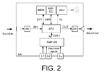
- FIG. 2 shows a second embodiment of a hearing aid according to the present disclosure.
- the hearing aid HA of FIG. 2 comprises the same functional units as the hearing aid discussed in connection with FIG. 1b .
- the embodiment of a hearing aid of FIG. 2 further comprises an alarm indication unit (ALU) adapted for issuing a warning or information signal to a user of the hearing aid (or to another person in the user's environment).
- the signal processing unit (SPU) is adapted to determine a hearing threshold difference measure comprising a sum ( ⁇ HT cur ) of the differences between currently estimated hearing thresholds (CEHT(f)) and presently used hearing thresholds (PUHT(f)), where f is frequency.
- the hearing thresholds are estimated at a number NHT of predefined frequencies, f 1 , f 2 , ..., f NHT .
- the signal processing unit (SPU) is e.g. adapted to determine when the hearing threshold difference measure exceeds a predetermined threshold value and to generate an alarm signal AL which is fed to the alarm indication unit (ALU).
- the alarm indication unit is adapted to issue a corresponding alarm (e.g. a visual and/or mechanical and/or acoustic alarm) in response to the alarm signal AL.
- the alarm signal may be transmitted to another device (e.g. via a network), e.g. for presentation to a caring person.
- ABR-SG stimulus signal generator
- ABR auditory brain stem response
- AMP amplifier unit
- FIG. 3 shows an embodiment of a binaural hearing aid system comprising first and second hearing instruments according to the present disclosure.
- the binaural hearing aid system comprises first and second (possibly, as in FIG. 3 , essentially identical) hearing instruments (HI-1, HI-2) adapted for being located at or in left and right ears of a user.
- the hearing instruments (HI-1, HI-2) of FIG. 3 are similar to the embodiment of a hearing aid (HA) shown in FIG. 2 .
- the hearing instruments (HI-1, HI-2) are additionally adapted for exchanging information between them via a wireless communication link, e.g. a specific inter-aural (IA) wireless link (IA-WL).
- IA inter-aural
- the two hearing instruments HI-1, HI-2 are adapted to (at least) allow the exchange of status signals, e.g. including the transmission of characteristics of the input signal received by a device at a particular ear to the device at the other ear, and/or (amplified) EEG-data (e.g. signals DAEI(1:N) or signals derived therefrom) picked up by one or more electrodes (E 1 , E 2 , ..., E N ) of the contra-lateral hearing instrument, cf. signal IAS.
- each hearing instrument comprises antenna and transceiver circuitry (here indicated by block IA-Rx / Tx).
- a microphone unit for converting an acoustic input sound to a first electric audio signal INm
- a wireless transceiver at least a receiver
- ANT and Rx / Tx -unit for receiving (and possibly) transmitting a signal from another device, e.g. an audio signal INw.
- the hearing instruments HI-1, HI-2 are assumed to process the audio signal of the forward path in the frequency domain, and therefore each comprise analysis (A-FB) and synthesis (S-FB) filter banks after and before the input (MIC and ANT, Rx / Tx ) and output (SP) transducers, respectively.
- A-FB analysis
- S-FB synthesis
- the analysis filter bank (A-FB) is adapted for splitting the (time varying) input signals (INm, INw) into a number NI of (time varying) signals IFB 1 , IFB 2 , ..., IFB NI , each comprising a distinct frequency range of the input signal.
- the input transducer (MIC and ANT, Rx / Tx) or the analysis filter bank (A-FB) is assumed to comprise an analogue to digital converter (AD).
- the synthesis filter bank (S-FB) is adapted for merging the a number NO of (time varying) signals OFB 1 , OFB 2 , ..., OFB NO , each comprising a distinct frequency range of the output signal into a (time varying) output signal (OUT), which is fed to the output transducer (SP) for conversion to an output sound for presentation to the user.
- the output transducer (SP) or the synthesis filter bank (S-FB) may comprise a digital to analogue converter (DA).
- DA digital to analogue converter
- Each of the hearing instruments HI-1, HI-2 comprises the same functional units as discussed for the hearing aid of FIG.
- the amplifier blocks further comprise a time to time-frequency conversion functionality (as indicated by the name of the amplifier unit AMP-AD-T->F) to provide the digital amplified brain signals (DAI1, DAI 2 , ..., DAI N ) in the frequency domain to adapt to further signal processing of the brain signals (determining the frequency dependent hearing thresholds) which may be performed by the signal processing unit (SPU) in the frequency domain.
- a time to time-frequency conversion functionality as indicated by the name of the amplifier unit AMP-AD-T->F
- DAI1 digital amplified brain signals
- DAI N digital amplified brain signals
- SPU signal processing unit
- the number of frequency units provided by the time to time-frequency conversion functionality may or may not be equal to the number NI of frequency bands of the forward path (e.g. smaller than NI).
- the digital amplified brain signals may be further processed in the signal processing unit (SPU) in the time domain, in which case the time to time-frequency conversion functionality of the amplifier can be omitted.
- SPU signal processing unit
- the hearing aid system further comprises an auxiliary device, e.g. an audio gateway device for receiving a number of audio signals and for transmitting at least one of the received audio signals to the hearing instruments (cf- transceivers (ANT, Rx / Tx), as e.g. illustrated FIG. 5 .
- the listening system is adapted to provide that a telephone input signal can be received in the hearing instruments via the audio gateway.
- the hearing aid system comprises a remote control acting as a user interface to the hearing instruments, e.g. to allow a user to change program (e.g. to activate or deactivate the ABR-recordal) or otherwise modify operational parameters of the hearing instruments, e.g. output volume of the loudspeaker.
- the remote control and the audio gateway are integrated into the same communications device (as e.g. illustrated in FIG. 5 ).
- the processing of (amplified) EEG-data e.g. signals DAEI(1:N) of the hearing instruments, or signals derived therefrom
- picked up by the one or more electrodes may be fully or partially performed in the auxiliary device (e.g. in the audio gateway/remote control device).
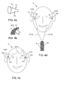
- FIG. 4 shows various elements of embodiments of a binaural hearing aid system according to the present disclosure.
- FIG. 4a shows an 'in the ear' part (ITE) of a hearing aid.
- the ITE part constitutes the hearing aid.
- the ITE part is adapted for being located fully or partially in the ear canal of the user U (cf. FIG. 4c, 4d ).
- the ITE part comprises two electrodes E1, E2 located on (or extending from) the surface of the housing of the ITE part.
- the ITE part e.g. comprises a mould adapted to a particular user's ear canal.
- the mould is typically made of a form stable plastic material by an injection moulding process or formed by a rapid prototyping process, e.g.
- FIG. 4b shows another embodiment of a (part of a) hearing aid according to the disclosure.
- FIG. 4b shows a part (BTE) of a 'behind the ear' hearing aid, where the BTE part is adapted for being located behind the ear (pinna, EAR in FIG. 4c and 4d ) of a user U.
- the BTE part comprises four electric terminals E3, E4, E5, E6, two of which are located on the face of the BTE part, which is adapted for being supported by the ridge where the ear (Pinna) is attached to the skull and two of which are located on the face of the BTE part adapted for being supported by the skull.
- the electric terminals are specifically adapted for picking up electric signals from the user's body, in particular from the brain, or related to a measure of cognitive load of the user.
- the electrical terminals may all serve the same purpose (e.g. measuring EEG) or different purposes.
- Electrical terminals (electrodes) for forming good electrical contact to the human body are e.g. described in literature concerning EEG-measurements (cf. e.g. US 2002/028991 or US 6, 574, 513 ).
- FIG. 4c shows an embodiment of a binaural hearing aid system according to the present disclosure comprising first and second hearing aids comprising (or being constituted by) left and right ear parts ITEI and ITEr, respectively, adapted for being located in left and right ear canals of a user, respectively (each ITE ear part being an ear part as shown in FIG. 4a ).
- the left and right hearing aids may comprise left and right ear parts BTEI and BTEr, respectively, adapted for being located behind left and right ears of a user, respectively (each BTE ear part being an ear part as shown in FIG. 4b ).
- the electric terminals (E1l, E2l and E1r, E2r of the left and right parts, respectively) are adapted to pick up a relatively low voltage (from the body) and is operationally connected to an amplifier for amplifying the low voltage signals and to transmit a value representative of the amplified voltage to a signal processor of the hearing aid (e.g. located in the ITE-part, in a BTE-part or in an auxiliary device, e.g. unit Aux in FIG. 4d or audio gateway/remote control (Aux) in FIG. 5 ).
- the hearing aid system comprises a reference terminal.
- At least one of the left and right hearing aids or hearing aid parts is adapted to allow transmission of signals from the (amplified, EEG) voltages picked up by the electrodes of the hearing aid in question to the other hearing aid (or to an auxiliary device performing the further processing of the voltages from (all) the electrodes) to allow the estimate of hearing thresholds of the user to be based on all available electrodes.
- each of the hearing aids (ITEI, ITEr) comprises antenna and transceiver circuitry to establish an interaural wireless link (IA-WL) between the two hearing aids as illustrated in FIG. 3 .
- FIG. 4d shows an embodiment of a binaural hearing aid system according to the present disclosure, which additionally comprises a number of electric terminals or sensors contributing to an estimate of the present cognitive load and/or a classification of the present environment of the user.
- the embodiment of FIG. 4d is identical to that of FIG. 4c apart from additionally comprising a body-mounted auxiliary device (Aux) optionally having 2 extra electric terminals, e.g. EEG electrodes, (En) mounted in good electrical contact with body tissue (but NOT on the head).
- the auxiliary device (Aux) comprises amplification and processing circuitry to allow a processing of the signals picked up by the electric terminals En.
- the auxiliary device (Aux) can act as a sensor and provide a processed input to the estimate of present cognitive load of the user (e.g. the estimate itself).
- the auxiliary device and at least one of the hearing aids (ITEI, ITEr) each comprise a wireless interface (comprising corresponding transceivers and antennas) for establishing a wireless link (ID-WL) between the devices for use in the exchange of data between the body-mounted auxiliary device (Aux) and the hearing aid(s) (ITEI, ITEr).
- the hearing aids (ITEI, ITEr) transmit the amplified voltages picked up by their respective electrodes to the auxiliary device, where the estimate of the hearing thresholds of the user is performed.
- the interaural link (IA-WL) of the embodiment of FIG. 4c may be dispensed with for the sake of the calculation of hearing thresholds (and corresponding required frequency dependent gains).
- the wireless links ID-WL between the auxiliary device and each of the hearing aids is preferably bidirectional, allowing the auxiliary device to forward revised hearing thresholds or gains to the hearing aids, when the hearing thresholds determined in the auxiliary device have changed more than predefined amounts.
- the wireless link may be based on near-field (capacitive of inductive coupling) or far-field (radiated fields) electromagnetic fields.
- the voltages from the electrodes of the auxiliary device may e.g. be used to classify ('filter') the voltages from the head mounted electrodes of the hearing aids, e.g. based on the correlation between the signals picked up by the head worn and body worn electrodes, respectively.
- the voltages picked up by the head worn electrodes (which are used for the estimate of hearing thresholds of the user) are NOT particularly related to hearing, if the correlation with the voltages picked up by the body worn electrodes is large (e.g. above a predefined value, depending on the specific correlation measure used).
- FIG. 5 shows an application scenario comprising an embodiment of a binaural hearing aid system comprising first and second hearing instruments and an auxiliary device according to the present disclosure.
- the auxiliary device comprises an audio selection device adapted for receiving a multitude of audio signals (here shown from an entertainment device, e.g. a TV (TV), a telephone apparatus, e.g. a cellular telephone (CT), a computer, e.g. a PC (PC), and an external microphone (xMIC) for picking up sounds x / S from the environment, e.g. the voice of another person).
- an entertainment device e.g. a TV (TV)
- a telephone apparatus e.g. a cellular telephone (CT)
- CT cellular telephone
- PC PC
- xMIC external microphone
- the microphone (AD-MIC) of the audio gateway device is adapted for picking up the user's own voice ( OV ) and to be capable of being connected to one or more of the external audio sources via wireless links (AD-WL), here assumed to be in the form of digital transmission links according to the Bluetooth standard as indicated by the Bluetooth transceiver (BT-Rx-Tx) in the audio gateway device (Aux).
- the links may alternatively be implemented in any other convenient wireless and/or wired manner, and according to any appropriate modulation type or transmission standard, possibly different for different audio sources.
- Other audio sources than the ones shown in FIG. 5 may be connectable to the audio gateway, e.g. an audio delivery device (such as a music player or the like).
- auxiliary device further comprises activation or deactivation of the ABR part of the hearing aid (including disabling the generation of (acoustic) ABR-stimuli and the processing of the voltages picked up by the electrodes of the hearing aids. This can e.g.
- Mode1, Mode2 the user interface
- Other 'normal' modes of operation of the binaural hearing aid system may likewise be selected by the user via the user interface (UI-ID).
- the hearing instruments are shown as devices mounted at the ear (behind the ear) of a user U.
- Each of the hearing instruments comprise a wireless transceiver, here indicated to be based on inductive communication (ID-Rx / Tx).
- the transceiver (at least) comprises an inductive receiver (i.e. an inductive coil, which is inductively coupled to a corresponding coil in a transceiver (ID-Rx-Tx) of the audio gateway device (Aux), which is adapted to receive an audio signal from the audio gateway device and any additional control or information signals.
- the inductive link ID-WL between the audio gateway device and the hearing instruments is indicated to be two-way, but may alternatively be one-way (from the auxiliary device to each of the hearing instruments).
- the audio gateway device Aux is shown to be carried around the neck of the user U in a neck-strap (NL).
- the neck-strap NL may have the combined function of a carrying strap and a loop antenna into which the audio signal from the audio gateway device is fed for better inductive coupling to the inductive transceiver of the listening device.
- An audio selection device which may be modified and used according to the present invention is e.g. described in EP 1 460 769 A1 , EP 1 981 253 A1 and in WO 2009/135872 A1 .
- FIG. 6 shows a third embodiment of a hearing aid according to the present disclosure.
- the hearing aid of FIG. 6 comprises the same functional elements as the embodiment of FIG. 1 b.
- the memory MEM is shown to have different sets of estimated hearing thresholds HT(f,t) of the user of the hearing aid as determined from the on-board auditory evoked potential (e.g. an auditory brainstem response) system.
- the on-board auditory evoked potential e.g. an auditory brainstem response
- the on-board auditory brainstem response system comprises test-signal generator (ABR-SG) and loudness model (LM) for providing masked electric stimuli (for being converted to acoustic stimuli via output transducer (OT)) and EEG-unit comprising electrodes (E 1 -E N ) and corresponding amplifier and AD-converter (AMP-AD) for providing digital amplified brain signals (DAEI 1 -DAEI N ).
- the signal processing unit (SPU) calculates (cf.
- the signal processing unit is adapted to store such sets of estimates of the users hearing threshold HT(f i ,t m ) in the memory according to a predefined scheme, e.g. with a predefined frequency.
- the memory is shown to include n + 1 sets of hearing thresholds corresponding to times to, t 1 , t 2 , ..., t n .
- the first set of hearing thresholds corresponding to time to may e.g. be a set of hearing thresholds that are stored during a fitting procedure, e.g. based on clinical measurements. Otherwise, they may represent the first set of hearing thresholds determined by the hearing aid system (e.g. in case NO fitting has been performed).
- the hearing thresholds are used to calculate an appropriate gain to be used in the gain unit (G) and (possibly in amended form depending on the input signal in question) applied to the input audio signal IN from the input transducer (IT) (or a signal derived therefrom, e.g.
- the 'presently used hearing thresholds' (PUHT) may e.g. be equal to a particular one of the sets of stored hearing thresholds, e.g.
- a test signal for the ABR-system is generated in the ABR-SG unit, e.g. as a sum of a series of three or more pure tones, each having a specified frequency, amplitude and phase, and wherein a frequency difference between the successive pure tones in the series is constant, f s , cf. e.g. WO 2006/003172 A1 .
- the test signal ABR-S is fed to a psycho acoustic model (here a loudness model), cf.
- the masked test signal MTS forming the output of the LM unit and comprising the processed audio signal in combination with the test stimuli is fed to the selector unit SEL.
- the pure test signal ABR-S is also fed to the selector unit SEL.
- the resulting output OUT from the selector unit (SEL) (for presentation to a user via output transducer OT) can be either of a) the masked test signal MTS, b) the pure test signal ABR-S or c) the processed audio signal PAS.
- the output signal from the selector unit is controlled by control signal SC from control unit (CNT).
- the hearing aid (HA) comprises an alarm indication unit (cf. e.g. FIG.
- Such alarm indication unit can e.g. be implemented, if operationally coupled to the control unit (CNT).
Landscapes
- Health & Medical Sciences (AREA)
- Life Sciences & Earth Sciences (AREA)
- Physics & Mathematics (AREA)
- Engineering & Computer Science (AREA)
- General Health & Medical Sciences (AREA)
- Otolaryngology (AREA)
- Acoustics & Sound (AREA)
- Pathology (AREA)
- Veterinary Medicine (AREA)
- Public Health (AREA)
- Animal Behavior & Ethology (AREA)
- Biophysics (AREA)
- Surgery (AREA)
- Biomedical Technology (AREA)
- Heart & Thoracic Surgery (AREA)
- Medical Informatics (AREA)
- Molecular Biology (AREA)
- Audiology, Speech & Language Pathology (AREA)
- Neurosurgery (AREA)
- Signal Processing (AREA)
- Multimedia (AREA)
- Psychology (AREA)
- Psychiatry (AREA)
- Measurement And Recording Of Electrical Phenomena And Electrical Characteristics Of The Living Body (AREA)
- Measurement Of The Respiration, Hearing Ability, Form, And Blood Characteristics Of Living Organisms (AREA)
Priority Applications (5)
| Application Number | Priority Date | Filing Date | Title |
|---|---|---|---|
| DK11185225.7T DK2581038T3 (en) | 2011-10-14 | 2011-10-14 | Automatic real-time hearing aid fitting based on auditory evoked potentials |
| EP11185225.7A EP2581038B1 (fr) | 2011-10-14 | 2011-10-14 | Appareil auditif automatique en temps réel basé sur des potentiels auditifs évoqués |
| CN201210387932.7A CN103052012B (zh) | 2011-10-14 | 2012-10-12 | 基于听觉诱发电位的自动实时助听器验配 |
| AU2012241067A AU2012241067B2 (en) | 2011-10-14 | 2012-10-12 | Automatic Real-Time Hearing Aid Fitting Based on Auditory Evoked Potentials |
| US13/651,032 US9635469B2 (en) | 2011-10-14 | 2012-10-12 | Automatic real-time hearing aid fitting based on auditory evoked potentials |
Applications Claiming Priority (1)
| Application Number | Priority Date | Filing Date | Title |
|---|---|---|---|
| EP11185225.7A EP2581038B1 (fr) | 2011-10-14 | 2011-10-14 | Appareil auditif automatique en temps réel basé sur des potentiels auditifs évoqués |
Publications (2)
| Publication Number | Publication Date |
|---|---|
| EP2581038A1 true EP2581038A1 (fr) | 2013-04-17 |
| EP2581038B1 EP2581038B1 (fr) | 2017-12-13 |
Family
ID=44785663
Family Applications (1)
| Application Number | Title | Priority Date | Filing Date |
|---|---|---|---|
| EP11185225.7A Active EP2581038B1 (fr) | 2011-10-14 | 2011-10-14 | Appareil auditif automatique en temps réel basé sur des potentiels auditifs évoqués |
Country Status (5)
| Country | Link |
|---|---|
| US (1) | US9635469B2 (fr) |
| EP (1) | EP2581038B1 (fr) |
| CN (1) | CN103052012B (fr) |
| AU (1) | AU2012241067B2 (fr) |
| DK (1) | DK2581038T3 (fr) |
Cited By (9)
| Publication number | Priority date | Publication date | Assignee | Title |
|---|---|---|---|---|
| EP2950555A1 (fr) | 2014-05-28 | 2015-12-02 | Oticon A/s | Adaptation d'une prothèse auditive automatique en temps réel sur la base des potentiels auditifs évoqués par des signaux acoustiques naturel |
| EP2997893A1 (fr) * | 2014-09-22 | 2016-03-23 | Oticon A/s | Système d'assistance auditive comprenant des électrodes pour capter des signaux d'ondes cérébrales |
| EP3056144A1 (fr) * | 2015-02-16 | 2016-08-17 | Interacoustics A/S | Système et procédé permettant de générer et d'enregistrer des réponses auditives stationnaires avec un stimulus de type parole |
| US9497530B1 (en) | 2015-08-31 | 2016-11-15 | Nura Holdings Pty Ltd | Personalization of auditory stimulus |
| US20170078803A1 (en) * | 2013-09-17 | 2017-03-16 | Oticon A/S | Hearing assistance device comprising an input transducer system |
| WO2018154289A3 (fr) * | 2017-02-23 | 2018-10-04 | Plextek Services Limited | Système, procédé, programme informatique et produit programme d'ordinateur pour détecter un changement de réponse auditive |
| CN110662151A (zh) * | 2018-06-29 | 2020-01-07 | 国际听力公司 | 使用语音信号确认用于婴幼儿的助听器的系统及方法 |
| US10708680B2 (en) | 2015-08-31 | 2020-07-07 | Nura Holdings Pty Ltd | Personalization of auditory stimulus |
| US10729387B2 (en) | 2014-07-15 | 2020-08-04 | The Regents Of The University Of California | Frequency-multiplexed speech-sound stimuli for hierarchical neural characterization of speech processing |
Families Citing this family (33)
| Publication number | Priority date | Publication date | Assignee | Title |
|---|---|---|---|---|
| EP2736273A1 (fr) * | 2012-11-23 | 2014-05-28 | Oticon A/s | Dispositif d'écoute comprenant une interface pour signaler la qualité de communication et/ou la charge du porteur sur l'environnement |
| US9191755B2 (en) * | 2012-12-14 | 2015-11-17 | Starkey Laboratories, Inc. | Spatial enhancement mode for hearing aids |
| US8965016B1 (en) | 2013-08-02 | 2015-02-24 | Starkey Laboratories, Inc. | Automatic hearing aid adaptation over time via mobile application |
| DK2835985T3 (en) * | 2013-08-08 | 2017-08-07 | Oticon As | Hearing aid and feedback reduction method |
| EP3140999B1 (fr) * | 2014-05-07 | 2018-03-14 | TDK Corporation | Microphone mems, et procédé de commande d'un microphone mems |
| EP2986029A1 (fr) * | 2014-08-14 | 2016-02-17 | Oticon A/s | Méthode et système pour modéliser un embout ajustement personnalisé |
| EP3197351A4 (fr) * | 2014-09-24 | 2018-05-30 | Vivosonic Inc. (legal-representative of Deceased) | Système, procédé et appareil pour détecter un signal de réponse évoquée |
| CN105530565B (zh) * | 2014-10-20 | 2021-02-19 | 哈曼国际工业有限公司 | 自动声音均衡装置 |
| US10181328B2 (en) * | 2014-10-21 | 2019-01-15 | Oticon A/S | Hearing system |
| EP3016407B1 (fr) * | 2014-10-28 | 2019-12-11 | Oticon A/s | Système auditif pour estimer un trajet de rétroaction d'un dispositif auditif |
| US10264370B2 (en) * | 2015-04-20 | 2019-04-16 | Oticon A/S | Hearing device configured to be placed in the ear canal of a user |
| KR102460393B1 (ko) | 2015-04-30 | 2022-11-01 | 삼성전자주식회사 | 사운드 출력 기기, 전자 장치 및 그 제어 방법 |
| WO2016175622A1 (fr) | 2015-04-30 | 2016-11-03 | Samsung Electronics Co., Ltd. | Appareil de sortie sonore, appareil électronique, et procédé de commande associé |
| US10183164B2 (en) * | 2015-08-27 | 2019-01-22 | Cochlear Limited | Stimulation parameter optimization |
| DK3139636T3 (da) * | 2015-09-07 | 2019-12-09 | Bernafon Ag | Høreanordning, der omfatter et tilbagekoblingsundertrykkelsessystem baseret på signalenergirelokation |
| US10013996B2 (en) * | 2015-09-18 | 2018-07-03 | Qualcomm Incorporated | Collaborative audio processing |
| CN109155888B (zh) | 2016-02-29 | 2021-11-05 | 韦斯伯技术公司 | 用于产生表示检测到声刺激的信号的压电mems装置 |
| DK3427496T3 (da) * | 2016-03-11 | 2020-04-06 | Widex As | Fremgangsmåde og hørehjælpemiddel til at håndtere streamet lyd |
| US10524064B2 (en) * | 2016-03-11 | 2019-12-31 | Widex A/S | Method and hearing assistive device for handling streamed audio |
| CN106073796A (zh) * | 2016-05-27 | 2016-11-09 | 深圳市易特科信息技术有限公司 | 基于骨传导的听力健康检测系统及方法 |
| US10091591B2 (en) * | 2016-06-08 | 2018-10-02 | Cochlear Limited | Electro-acoustic adaption in a hearing prosthesis |
| CN107170463A (zh) * | 2017-05-09 | 2017-09-15 | 佛山博智医疗科技有限公司 | 音频信号调节方法及系统 |
| WO2019067551A1 (fr) * | 2017-09-27 | 2019-04-04 | Northwestern University | Procédés et systèmes pour déterminer la représentation neuronale de sons traités numériquement |
| DE102018204950A1 (de) * | 2018-04-03 | 2019-10-10 | Sivantos Pte. Ltd. | Hörsystem sowie Zusatzgerät für ein solches |
| US20200021927A1 (en) * | 2018-07-11 | 2020-01-16 | Harman International Industries, Incorporated | Method for customizing a hearing device at point of sale |
| EP3939336A4 (fr) * | 2019-03-14 | 2022-12-07 | Qualcomm Technologies, Inc. | Dispositif mems piézoélectrique à seuil adaptatif pour la détection d'un stimulus acoustique |
| WO2020186265A1 (fr) | 2019-03-14 | 2020-09-17 | Vesper Technologies Inc. | Microphone ayant une sortie numérique déterminée à différents niveaux de consommation d'énergie |
| US11726105B2 (en) | 2019-06-26 | 2023-08-15 | Qualcomm Incorporated | Piezoelectric accelerometer with wake function |
| CN111417062A (zh) * | 2020-04-27 | 2020-07-14 | 陈一波 | 一种助听器验配处方 |
| EP4228740A1 (fr) * | 2020-10-15 | 2023-08-23 | Cochlear Limited | Autoajustement de prothèse |
| GB2613772A (en) | 2021-11-05 | 2023-06-21 | Ucl Business Ltd | A neural-inspired audio signal processor |
| CN114827864B (zh) * | 2022-06-28 | 2022-09-23 | 武汉左点科技有限公司 | 骨传导助听器声音信号匹配增益补偿方法及设备 |
| CN117179787B (zh) * | 2023-11-06 | 2024-02-06 | 苏州海臻医疗器械有限公司 | 一种听觉诱发电位检测用头部穿戴设备及其检测方法 |
Citations (13)
| Publication number | Priority date | Publication date | Assignee | Title |
|---|---|---|---|---|
| EP1073314A1 (fr) * | 1999-07-27 | 2001-01-31 | Siemens Audiologische Technik GmbH | Procédé d'adaptation d'une prothése auditive et prothése auditive |
| US20020028991A1 (en) | 2000-09-01 | 2002-03-07 | Medtronic, Inc. | Skin-mounted electrodes with nano spikes |
| EP1295509A2 (fr) | 2000-06-30 | 2003-03-26 | Phonak Ag | Procede de fabrication d'otoplastiques et otoplastique y relatif |
| US6574513B1 (en) | 2000-10-03 | 2003-06-03 | Brainmaster Technologies, Inc. | EEG electrode assemblies |
| EP1460769A1 (fr) | 2003-03-18 | 2004-09-22 | Phonak Communications Ag | Emetteur-récepteur mobile et module électronique pour la commande du émetteur-récepteur |
| WO2006003172A1 (fr) | 2004-07-02 | 2006-01-12 | Maico Diagnostic Gmbh | Procede de conception de stimuli acoustique dans le domaine spectral pour l'enregistrement de reponses auditives en regime stable (assr) |
| US7035745B2 (en) | 2003-02-07 | 2006-04-25 | Oticon A/S | Statistical test method for objective verification of auditory steady-state responses (ASSR) in the frequency domain |
| EP1981253A1 (fr) | 2007-04-10 | 2008-10-15 | Oticon A/S | Interface utilisateur pour un dispositif de communications |
| WO2009135872A1 (fr) | 2008-05-07 | 2009-11-12 | Oticon A/S | Liaison sans fil unidirectionnelle à courte portée |
| EP2200347A2 (fr) | 2008-12-22 | 2010-06-23 | Oticon A/S | Procédé de fonctionnement d'un instrument d'écoute basé sur l'évaluation d'une charge cognitive actuelle d'un utilisateur, et système d'assistance auditive |
| WO2010149157A1 (fr) | 2009-06-26 | 2010-12-29 | Widex A/S | Appareil de monitoring d'eeg et procédé de présentation de messages dans celui-ci |
| WO2011006681A1 (fr) | 2009-07-13 | 2011-01-20 | Widex A/S | Prothèse auditive adaptée pour détecter des ondes cérébrales et procédé d'adaptation d'une telle prothèse auditive |
| US20110188664A1 (en) * | 2009-07-03 | 2011-08-04 | Koji Morikawa | Device, method, and program for adjustment of hearing aid |
Family Cites Families (7)
| Publication number | Priority date | Publication date | Assignee | Title |
|---|---|---|---|---|
| WO2005072168A2 (fr) * | 2004-01-20 | 2005-08-11 | Sound Techniques Systems Llc | Procede et appareil ameliorant la perception auditive de patienta atteints de perte auditive |
| JP4982573B2 (ja) * | 2007-03-23 | 2012-07-25 | ヴェーデクス・アクティーセルスカプ | 個人の聴力の他覚的測定システムおよび方法 |
| DK2200347T3 (da) * | 2008-12-22 | 2013-04-15 | Oticon As | Fremgangsmåde til drift af et høreinstrument baseret på en estimering af den aktuelle kognitive belastning af en bruger og et høreapparatsystem og tilsvarende anordning |
| US8447042B2 (en) * | 2010-02-16 | 2013-05-21 | Nicholas Hall Gurin | System and method for audiometric assessment and user-specific audio enhancement |
| US9124995B2 (en) * | 2010-12-30 | 2015-09-01 | Starkey Laboratories, Inc. | Revision control within hearing-aid fitting software |
| DE102011106634B4 (de) * | 2011-07-04 | 2015-02-19 | Eberhard-Karls-Universität Tübingen Universitätsklinikum | Hörgerät und Verfahren zum Eliminieren akustischer Rückkopplungen bei Verstärkung akustischer Signale |
| WO2013017169A1 (fr) * | 2011-08-03 | 2013-02-07 | Widex A/S | Prothèse auditive dotée d'une capacité de réglage automatique |
-
2011
- 2011-10-14 DK DK11185225.7T patent/DK2581038T3/en active
- 2011-10-14 EP EP11185225.7A patent/EP2581038B1/fr active Active
-
2012
- 2012-10-12 CN CN201210387932.7A patent/CN103052012B/zh active Active
- 2012-10-12 US US13/651,032 patent/US9635469B2/en active Active
- 2012-10-12 AU AU2012241067A patent/AU2012241067B2/en not_active Ceased
Patent Citations (13)
| Publication number | Priority date | Publication date | Assignee | Title |
|---|---|---|---|---|
| EP1073314A1 (fr) * | 1999-07-27 | 2001-01-31 | Siemens Audiologische Technik GmbH | Procédé d'adaptation d'une prothése auditive et prothése auditive |
| EP1295509A2 (fr) | 2000-06-30 | 2003-03-26 | Phonak Ag | Procede de fabrication d'otoplastiques et otoplastique y relatif |
| US20020028991A1 (en) | 2000-09-01 | 2002-03-07 | Medtronic, Inc. | Skin-mounted electrodes with nano spikes |
| US6574513B1 (en) | 2000-10-03 | 2003-06-03 | Brainmaster Technologies, Inc. | EEG electrode assemblies |
| US7035745B2 (en) | 2003-02-07 | 2006-04-25 | Oticon A/S | Statistical test method for objective verification of auditory steady-state responses (ASSR) in the frequency domain |
| EP1460769A1 (fr) | 2003-03-18 | 2004-09-22 | Phonak Communications Ag | Emetteur-récepteur mobile et module électronique pour la commande du émetteur-récepteur |
| WO2006003172A1 (fr) | 2004-07-02 | 2006-01-12 | Maico Diagnostic Gmbh | Procede de conception de stimuli acoustique dans le domaine spectral pour l'enregistrement de reponses auditives en regime stable (assr) |
| EP1981253A1 (fr) | 2007-04-10 | 2008-10-15 | Oticon A/S | Interface utilisateur pour un dispositif de communications |
| WO2009135872A1 (fr) | 2008-05-07 | 2009-11-12 | Oticon A/S | Liaison sans fil unidirectionnelle à courte portée |
| EP2200347A2 (fr) | 2008-12-22 | 2010-06-23 | Oticon A/S | Procédé de fonctionnement d'un instrument d'écoute basé sur l'évaluation d'une charge cognitive actuelle d'un utilisateur, et système d'assistance auditive |
| WO2010149157A1 (fr) | 2009-06-26 | 2010-12-29 | Widex A/S | Appareil de monitoring d'eeg et procédé de présentation de messages dans celui-ci |
| US20110188664A1 (en) * | 2009-07-03 | 2011-08-04 | Koji Morikawa | Device, method, and program for adjustment of hearing aid |
| WO2011006681A1 (fr) | 2009-07-13 | 2011-01-20 | Widex A/S | Prothèse auditive adaptée pour détecter des ondes cérébrales et procédé d'adaptation d'une telle prothèse auditive |
Non-Patent Citations (6)
| Title |
|---|
| "Models for Just-Noticeable Variations", pages: 194 - 202 |
| ARTHUR SCHAUB: "Digital hearing Aids", 2008, THIEME MEDICAL. PUB. |
| ERIKA SKOE, NINA KRAUS, AUDITORY BRAIN STEM RESPONSE TO COMPLEX SOUNDS: A TUTORIAL, EAR AND HEARING, vol. 31, no. 3, 2010, pages 302 - 324 |
| FASTL, ZWICKER: "Masking", 2007, pages: 61 - 110 |
| H. FASTL, E. ZWICKER: "Psychoacoustics, Facts and Models", 2007, SPRINGER |
| STURZEBECHER, E., CEBULLA, M., ELBERLING. C., BERGER, T.: "New efficient stimuli for evoking frequency-specific auditory steady-state responses", J. AM. ACAD. AUDIOL., vol. 17, 2006, pages 448 - 461 |
Cited By (17)
| Publication number | Priority date | Publication date | Assignee | Title |
|---|---|---|---|---|
| US10182298B2 (en) * | 2013-09-17 | 2019-01-15 | Oticfon A/S | Hearing assistance device comprising an input transducer system |
| US20170078803A1 (en) * | 2013-09-17 | 2017-03-16 | Oticon A/S | Hearing assistance device comprising an input transducer system |
| US9426582B2 (en) | 2014-05-28 | 2016-08-23 | Oticon A/S | Automatic real-time hearing aid fitting based on auditory evoked potentials evoked by natural sound signals |
| EP2950555A1 (fr) | 2014-05-28 | 2015-12-02 | Oticon A/s | Adaptation d'une prothèse auditive automatique en temps réel sur la base des potentiels auditifs évoqués par des signaux acoustiques naturel |
| US10729387B2 (en) | 2014-07-15 | 2020-08-04 | The Regents Of The University Of California | Frequency-multiplexed speech-sound stimuli for hierarchical neural characterization of speech processing |
| EP2997893A1 (fr) * | 2014-09-22 | 2016-03-23 | Oticon A/s | Système d'assistance auditive comprenant des électrodes pour capter des signaux d'ondes cérébrales |
| US9700261B2 (en) | 2014-09-22 | 2017-07-11 | Oticon A/S | Hearing assistance system comprising electrodes for picking up brain wave signals |
| EP3056144A1 (fr) * | 2015-02-16 | 2016-08-17 | Interacoustics A/S | Système et procédé permettant de générer et d'enregistrer des réponses auditives stationnaires avec un stimulus de type parole |
| US11832952B2 (en) | 2015-02-16 | 2023-12-05 | Interacoustics A/S | System and method for generating and recording auditory steady-state responses with a speech-like stimulus |
| US10736535B2 (en) | 2015-02-16 | 2020-08-11 | Interacoustics A/S | System and method for generating and recording auditory steady-state responses with a speech-like stimulus |
| US10708680B2 (en) | 2015-08-31 | 2020-07-07 | Nura Holdings Pty Ltd | Personalization of auditory stimulus |
| US10154333B2 (en) | 2015-08-31 | 2018-12-11 | Nura Holdings Pty Ltd | Personalization of auditory stimulus |
| US9794672B2 (en) | 2015-08-31 | 2017-10-17 | Nura Holdings Pty Ltd | Personalization of auditory stimulus |
| EP3345263B1 (fr) | 2015-08-31 | 2022-12-21 | Nura Holdings PTY Ltd | Personnalisation de stimulus auditif |
| US9497530B1 (en) | 2015-08-31 | 2016-11-15 | Nura Holdings Pty Ltd | Personalization of auditory stimulus |
| WO2018154289A3 (fr) * | 2017-02-23 | 2018-10-04 | Plextek Services Limited | Système, procédé, programme informatique et produit programme d'ordinateur pour détecter un changement de réponse auditive |
| CN110662151A (zh) * | 2018-06-29 | 2020-01-07 | 国际听力公司 | 使用语音信号确认用于婴幼儿的助听器的系统及方法 |
Also Published As
| Publication number | Publication date |
|---|---|
| US9635469B2 (en) | 2017-04-25 |
| US20130101128A1 (en) | 2013-04-25 |
| EP2581038B1 (fr) | 2017-12-13 |
| DK2581038T3 (en) | 2018-02-19 |
| AU2012241067A1 (en) | 2013-05-02 |
| AU2012241067B2 (en) | 2017-03-09 |
| CN103052012B (zh) | 2018-07-03 |
| CN103052012A (zh) | 2013-04-17 |
Similar Documents
| Publication | Publication Date | Title |
|---|---|---|
| EP2581038B1 (fr) | Appareil auditif automatique en temps réel basé sur des potentiels auditifs évoqués | |
| US9426582B2 (en) | Automatic real-time hearing aid fitting based on auditory evoked potentials evoked by natural sound signals | |
| EP2717597B1 (fr) | Dispositif d'aide auditive avec un traitement audio dépendant des ondes cérébrales | |
| EP3313092A1 (fr) | Système auditif pour surveiller un paramètre lié à la santé | |
| US11564048B2 (en) | Signal processing in a hearing device | |
| EP3700229A1 (fr) | Instrument auditif configurable | |
| EP2736273A1 (fr) | Dispositif d'écoute comprenant une interface pour signaler la qualité de communication et/ou la charge du porteur sur l'environnement | |
| US11671769B2 (en) | Personalization of algorithm parameters of a hearing device | |
| CN105376684B (zh) | 包括植入部分的具有改善的信号处理的助听系统 | |
| US11330375B2 (en) | Method of adaptive mixing of uncorrelated or correlated noisy signals, and a hearing device | |
| EP3934278A1 (fr) | Prothèse auditive comprenant un traitement binaural et un système d'aide auditive binaurale | |
| US20220264232A1 (en) | A hearing aid comprising an open loop gain estimator | |
| Lunner et al. | Automatic real-time hearing aid fitting based on auditory evoked potentials | |
| US20220174436A1 (en) | Method for calculating gain in a hearing aid | |
| US20230284934A1 (en) | Hearing device system and method for performing a test of a hearing device user's hearing capabilities | |
| EP4324392A2 (fr) | Unité de test de détection de modulation spectrale-temporelle | |
| US11528566B2 (en) | Battery life estimation for hearing instruments | |
| US20240089669A1 (en) | Method for customizing a hearing apparatus, hearing apparatus and computer program product |
Legal Events
| Date | Code | Title | Description |
|---|---|---|---|
| PUAI | Public reference made under article 153(3) epc to a published international application that has entered the european phase |
Free format text: ORIGINAL CODE: 0009012 |
|
| AK | Designated contracting states |
Kind code of ref document: A1 Designated state(s): AL AT BE BG CH CY CZ DE DK EE ES FI FR GB GR HR HU IE IS IT LI LT LU LV MC MK MT NL NO PL PT RO RS SE SI SK SM TR |
|
| AX | Request for extension of the european patent |
Extension state: BA ME |
|
| 17P | Request for examination filed |
Effective date: 20131017 |
|
| RBV | Designated contracting states (corrected) |
Designated state(s): AL AT BE BG CH CY CZ DE DK EE ES FI FR GB GR HR HU IE IS IT LI LT LU LV MC MK MT NL NO PL PT RO RS SE SI SK SM TR |
|
| 17Q | First examination report despatched |
Effective date: 20160811 |
|
| REG | Reference to a national code |
Ref country code: DE Ref legal event code: R079 Ref document number: 602011044110 Country of ref document: DE Free format text: PREVIOUS MAIN CLASS: A61B0005048400 Ipc: G06F0003010000 |
|
| GRAP | Despatch of communication of intention to grant a patent |
Free format text: ORIGINAL CODE: EPIDOSNIGR1 |
|
| RIC1 | Information provided on ipc code assigned before grant |
Ipc: H04R 25/00 20060101ALI20170530BHEP Ipc: G06F 3/01 20060101AFI20170530BHEP Ipc: A61B 5/0484 20060101ALI20170530BHEP Ipc: A61B 5/00 20060101ALI20170530BHEP Ipc: A61B 5/12 20060101ALI20170530BHEP |
|
| INTG | Intention to grant announced |
Effective date: 20170703 |
|
| GRAS | Grant fee paid |
Free format text: ORIGINAL CODE: EPIDOSNIGR3 |
|
| GRAA | (expected) grant |
Free format text: ORIGINAL CODE: 0009210 |
|
| AK | Designated contracting states |
Kind code of ref document: B1 Designated state(s): AL AT BE BG CH CY CZ DE DK EE ES FI FR GB GR HR HU IE IS IT LI LT LU LV MC MK MT NL NO PL PT RO RS SE SI SK SM TR |
|
| REG | Reference to a national code |
Ref country code: GB Ref legal event code: FG4D |
|
| REG | Reference to a national code |
Ref country code: AT Ref legal event code: REF Ref document number: 954991 Country of ref document: AT Kind code of ref document: T Effective date: 20171215 Ref country code: CH Ref legal event code: EP |
|
| REG | Reference to a national code |
Ref country code: IE Ref legal event code: FG4D |
|
| REG | Reference to a national code |
Ref country code: DE Ref legal event code: R096 Ref document number: 602011044110 Country of ref document: DE |
|
| REG | Reference to a national code |
Ref country code: DK Ref legal event code: T3 Effective date: 20180216 |
|
| REG | Reference to a national code |
Ref country code: NL Ref legal event code: MP Effective date: 20171213 |
|
| REG | Reference to a national code |
Ref country code: LT Ref legal event code: MG4D |
|
| PG25 | Lapsed in a contracting state [announced via postgrant information from national office to epo] |
Ref country code: NO Free format text: LAPSE BECAUSE OF FAILURE TO SUBMIT A TRANSLATION OF THE DESCRIPTION OR TO PAY THE FEE WITHIN THE PRESCRIBED TIME-LIMIT Effective date: 20180313 Ref country code: LT Free format text: LAPSE BECAUSE OF FAILURE TO SUBMIT A TRANSLATION OF THE DESCRIPTION OR TO PAY THE FEE WITHIN THE PRESCRIBED TIME-LIMIT Effective date: 20171213 Ref country code: SE Free format text: LAPSE BECAUSE OF FAILURE TO SUBMIT A TRANSLATION OF THE DESCRIPTION OR TO PAY THE FEE WITHIN THE PRESCRIBED TIME-LIMIT Effective date: 20171213 Ref country code: FI Free format text: LAPSE BECAUSE OF FAILURE TO SUBMIT A TRANSLATION OF THE DESCRIPTION OR TO PAY THE FEE WITHIN THE PRESCRIBED TIME-LIMIT Effective date: 20171213 |
|
| REG | Reference to a national code |
Ref country code: AT Ref legal event code: MK05 Ref document number: 954991 Country of ref document: AT Kind code of ref document: T Effective date: 20171213 |
|
| PG25 | Lapsed in a contracting state [announced via postgrant information from national office to epo] |
Ref country code: RS Free format text: LAPSE BECAUSE OF FAILURE TO SUBMIT A TRANSLATION OF THE DESCRIPTION OR TO PAY THE FEE WITHIN THE PRESCRIBED TIME-LIMIT Effective date: 20171213 Ref country code: HR Free format text: LAPSE BECAUSE OF FAILURE TO SUBMIT A TRANSLATION OF THE DESCRIPTION OR TO PAY THE FEE WITHIN THE PRESCRIBED TIME-LIMIT Effective date: 20171213 Ref country code: BG Free format text: LAPSE BECAUSE OF FAILURE TO SUBMIT A TRANSLATION OF THE DESCRIPTION OR TO PAY THE FEE WITHIN THE PRESCRIBED TIME-LIMIT Effective date: 20180313 Ref country code: LV Free format text: LAPSE BECAUSE OF FAILURE TO SUBMIT A TRANSLATION OF THE DESCRIPTION OR TO PAY THE FEE WITHIN THE PRESCRIBED TIME-LIMIT Effective date: 20171213 Ref country code: GR Free format text: LAPSE BECAUSE OF FAILURE TO SUBMIT A TRANSLATION OF THE DESCRIPTION OR TO PAY THE FEE WITHIN THE PRESCRIBED TIME-LIMIT Effective date: 20180314 |
|
| PG25 | Lapsed in a contracting state [announced via postgrant information from national office to epo] |
Ref country code: NL Free format text: LAPSE BECAUSE OF FAILURE TO SUBMIT A TRANSLATION OF THE DESCRIPTION OR TO PAY THE FEE WITHIN THE PRESCRIBED TIME-LIMIT Effective date: 20171213 |
|
| PG25 | Lapsed in a contracting state [announced via postgrant information from national office to epo] |
Ref country code: CY Free format text: LAPSE BECAUSE OF FAILURE TO SUBMIT A TRANSLATION OF THE DESCRIPTION OR TO PAY THE FEE WITHIN THE PRESCRIBED TIME-LIMIT Effective date: 20171213 Ref country code: EE Free format text: LAPSE BECAUSE OF FAILURE TO SUBMIT A TRANSLATION OF THE DESCRIPTION OR TO PAY THE FEE WITHIN THE PRESCRIBED TIME-LIMIT Effective date: 20171213 Ref country code: CZ Free format text: LAPSE BECAUSE OF FAILURE TO SUBMIT A TRANSLATION OF THE DESCRIPTION OR TO PAY THE FEE WITHIN THE PRESCRIBED TIME-LIMIT Effective date: 20171213 Ref country code: ES Free format text: LAPSE BECAUSE OF FAILURE TO SUBMIT A TRANSLATION OF THE DESCRIPTION OR TO PAY THE FEE WITHIN THE PRESCRIBED TIME-LIMIT Effective date: 20171213 Ref country code: SK Free format text: LAPSE BECAUSE OF FAILURE TO SUBMIT A TRANSLATION OF THE DESCRIPTION OR TO PAY THE FEE WITHIN THE PRESCRIBED TIME-LIMIT Effective date: 20171213 |
|
| PG25 | Lapsed in a contracting state [announced via postgrant information from national office to epo] |
Ref country code: IS Free format text: LAPSE BECAUSE OF FAILURE TO SUBMIT A TRANSLATION OF THE DESCRIPTION OR TO PAY THE FEE WITHIN THE PRESCRIBED TIME-LIMIT Effective date: 20180413 Ref country code: IT Free format text: LAPSE BECAUSE OF FAILURE TO SUBMIT A TRANSLATION OF THE DESCRIPTION OR TO PAY THE FEE WITHIN THE PRESCRIBED TIME-LIMIT Effective date: 20171213 Ref country code: SM Free format text: LAPSE BECAUSE OF FAILURE TO SUBMIT A TRANSLATION OF THE DESCRIPTION OR TO PAY THE FEE WITHIN THE PRESCRIBED TIME-LIMIT Effective date: 20171213 Ref country code: RO Free format text: LAPSE BECAUSE OF FAILURE TO SUBMIT A TRANSLATION OF THE DESCRIPTION OR TO PAY THE FEE WITHIN THE PRESCRIBED TIME-LIMIT Effective date: 20171213 Ref country code: AT Free format text: LAPSE BECAUSE OF FAILURE TO SUBMIT A TRANSLATION OF THE DESCRIPTION OR TO PAY THE FEE WITHIN THE PRESCRIBED TIME-LIMIT Effective date: 20171213 Ref country code: PL Free format text: LAPSE BECAUSE OF FAILURE TO SUBMIT A TRANSLATION OF THE DESCRIPTION OR TO PAY THE FEE WITHIN THE PRESCRIBED TIME-LIMIT Effective date: 20171213 |
|
| REG | Reference to a national code |
Ref country code: DE Ref legal event code: R097 Ref document number: 602011044110 Country of ref document: DE |
|
| REG | Reference to a national code |
Ref country code: FR Ref legal event code: PLFP Year of fee payment: 8 |
|
| PLBE | No opposition filed within time limit |
Free format text: ORIGINAL CODE: 0009261 |
|
| STAA | Information on the status of an ep patent application or granted ep patent |
Free format text: STATUS: NO OPPOSITION FILED WITHIN TIME LIMIT |
|
| 26N | No opposition filed |
Effective date: 20180914 |
|
| PG25 | Lapsed in a contracting state [announced via postgrant information from national office to epo] |
Ref country code: SI Free format text: LAPSE BECAUSE OF FAILURE TO SUBMIT A TRANSLATION OF THE DESCRIPTION OR TO PAY THE FEE WITHIN THE PRESCRIBED TIME-LIMIT Effective date: 20171213 |
|
| REG | Reference to a national code |
Ref country code: BE Ref legal event code: MM Effective date: 20181031 |
|
| PG25 | Lapsed in a contracting state [announced via postgrant information from national office to epo] |
Ref country code: LU Free format text: LAPSE BECAUSE OF NON-PAYMENT OF DUE FEES Effective date: 20181014 Ref country code: MC Free format text: LAPSE BECAUSE OF FAILURE TO SUBMIT A TRANSLATION OF THE DESCRIPTION OR TO PAY THE FEE WITHIN THE PRESCRIBED TIME-LIMIT Effective date: 20171213 |
|
| REG | Reference to a national code |
Ref country code: IE Ref legal event code: MM4A |
|
| PG25 | Lapsed in a contracting state [announced via postgrant information from national office to epo] |
Ref country code: BE Free format text: LAPSE BECAUSE OF NON-PAYMENT OF DUE FEES Effective date: 20181031 |
|
| PG25 | Lapsed in a contracting state [announced via postgrant information from national office to epo] |
Ref country code: IE Free format text: LAPSE BECAUSE OF NON-PAYMENT OF DUE FEES Effective date: 20181014 |
|
| PG25 | Lapsed in a contracting state [announced via postgrant information from national office to epo] |
Ref country code: MT Free format text: LAPSE BECAUSE OF NON-PAYMENT OF DUE FEES Effective date: 20181014 |
|
| PG25 | Lapsed in a contracting state [announced via postgrant information from national office to epo] |
Ref country code: TR Free format text: LAPSE BECAUSE OF FAILURE TO SUBMIT A TRANSLATION OF THE DESCRIPTION OR TO PAY THE FEE WITHIN THE PRESCRIBED TIME-LIMIT Effective date: 20171213 |
|
| PG25 | Lapsed in a contracting state [announced via postgrant information from national office to epo] |
Ref country code: PT Free format text: LAPSE BECAUSE OF FAILURE TO SUBMIT A TRANSLATION OF THE DESCRIPTION OR TO PAY THE FEE WITHIN THE PRESCRIBED TIME-LIMIT Effective date: 20171213 |
|
| PG25 | Lapsed in a contracting state [announced via postgrant information from national office to epo] |
Ref country code: MK Free format text: LAPSE BECAUSE OF NON-PAYMENT OF DUE FEES Effective date: 20171213 Ref country code: HU Free format text: LAPSE BECAUSE OF FAILURE TO SUBMIT A TRANSLATION OF THE DESCRIPTION OR TO PAY THE FEE WITHIN THE PRESCRIBED TIME-LIMIT; INVALID AB INITIO Effective date: 20111014 |
|
| PG25 | Lapsed in a contracting state [announced via postgrant information from national office to epo] |
Ref country code: AL Free format text: LAPSE BECAUSE OF FAILURE TO SUBMIT A TRANSLATION OF THE DESCRIPTION OR TO PAY THE FEE WITHIN THE PRESCRIBED TIME-LIMIT Effective date: 20171213 |
|
| PGFP | Annual fee paid to national office [announced via postgrant information from national office to epo] |
Ref country code: GB Payment date: 20230928 Year of fee payment: 13 |
|
| PGFP | Annual fee paid to national office [announced via postgrant information from national office to epo] |
Ref country code: FR Payment date: 20230928 Year of fee payment: 13 Ref country code: DK Payment date: 20230928 Year of fee payment: 13 |
|
| PGFP | Annual fee paid to national office [announced via postgrant information from national office to epo] |
Ref country code: DE Payment date: 20230928 Year of fee payment: 13 Ref country code: CH Payment date: 20231102 Year of fee payment: 13 |