EP2580952A1 - A flow monitor and agricultural implement with such - Google Patents
A flow monitor and agricultural implement with such Download PDFInfo
- Publication number
- EP2580952A1 EP2580952A1 EP12186810.3A EP12186810A EP2580952A1 EP 2580952 A1 EP2580952 A1 EP 2580952A1 EP 12186810 A EP12186810 A EP 12186810A EP 2580952 A1 EP2580952 A1 EP 2580952A1
- Authority
- EP
- European Patent Office
- Prior art keywords
- temperature
- signal
- temperature signal
- sensing device
- outlet
- Prior art date
- Legal status (The legal status is an assumption and is not a legal conclusion. Google has not performed a legal analysis and makes no representation as to the accuracy of the status listed.)
- Withdrawn
Links
- 230000011664 signaling Effects 0.000 claims abstract description 22
- 238000012544 monitoring process Methods 0.000 claims abstract description 5
- QGZKDVFQNNGYKY-UHFFFAOYSA-N Ammonia Chemical group N QGZKDVFQNNGYKY-UHFFFAOYSA-N 0.000 claims description 14
- 230000008878 coupling Effects 0.000 claims description 13
- 238000010168 coupling process Methods 0.000 claims description 13
- 238000005859 coupling reaction Methods 0.000 claims description 13
- 230000007246 mechanism Effects 0.000 claims description 10
- 239000002689 soil Substances 0.000 claims description 10
- 230000000007 visual effect Effects 0.000 claims description 9
- 230000000712 assembly Effects 0.000 claims description 6
- 238000000429 assembly Methods 0.000 claims description 6
- 230000004913 activation Effects 0.000 claims description 2
- 229910021529 ammonia Inorganic materials 0.000 description 5
- 239000000126 substance Substances 0.000 description 4
- 230000008901 benefit Effects 0.000 description 2
- 239000007788 liquid Substances 0.000 description 2
- 238000011144 upstream manufacturing Methods 0.000 description 2
- 238000012993 chemical processing Methods 0.000 description 1
- 238000010276 construction Methods 0.000 description 1
- 239000007789 gas Substances 0.000 description 1
- 238000012986 modification Methods 0.000 description 1
- 230000004048 modification Effects 0.000 description 1
- 238000012806 monitoring device Methods 0.000 description 1
- 239000007787 solid Substances 0.000 description 1
- 239000007921 spray Substances 0.000 description 1
Images
Classifications
-
- A—HUMAN NECESSITIES
- A01—AGRICULTURE; FORESTRY; ANIMAL HUSBANDRY; HUNTING; TRAPPING; FISHING
- A01C—PLANTING; SOWING; FERTILISING
- A01C21/00—Methods of fertilising, sowing or planting
-
- A—HUMAN NECESSITIES
- A01—AGRICULTURE; FORESTRY; ANIMAL HUSBANDRY; HUNTING; TRAPPING; FISHING
- A01C—PLANTING; SOWING; FERTILISING
- A01C23/00—Distributing devices specially adapted for liquid manure or other fertilising liquid, including ammonia, e.g. transport tanks or sprinkling wagons
- A01C23/007—Metering or regulating systems
Definitions
- the present disclosure generally relates to a flow monitor for monitoring application of a matter through a first flow path having a first outlet and a second flow path having a second outlet.
- the invention further relates to an agricultural implement with such flow monitor.
- Flow monitors can be used to monitor flow of a chemical through a pipe to indicate if the pipe becomes obstructed or blocked. For example, the flow of a chemical being applied to soil by an agricultural implement can become reduced or stopped if distribution lines become clogged or broken.
- agricultural implements commonly include control valves with flow sensors positioned upstream of the distribution lines.
- U.S. Patent No. 4,458,609 discloses such a device including a heat exchanger that maintains anhydrous ammonia in a liquid state so that a flow control valve can accurately control the flow rate of ammonia to a manifold.
- Separate lines connected to the manifold downstream of the control valve distribute the ammonia to nozzles associated with earthworking tools to place the ammonia into the soil.
- U.S. Patent Publication No. 2010/0073473 discloses a pressure gauge that is used to monitor pressure at a distributor. A camera is positioned to view the pressure gauge and to transmit and image of the pressure gauge to a monitor in an operator cab of a tractor pulling the implement. Separate distribution lines connected to the distributor disperse the ammonia to nozzles associated with earthworking tools to place the ammonia into the soil.
- One object of the invention is to provide an alternative flow monitoring device for an agricultural implement in order to lower costs and complexity.
- a flow monitor of the above mentioned manner is provided with a first temperature sensing device positioned adjacent the first outlet and producing a first temperature signal, a second temperature sensing device is positioned adjacent the second outlet and producing a second temperature signal.
- the flow monitor further comprising a signaling device, remote from the first outlet and remote from the second outlet, the signaling device is activated when the first temperature signal differs from the second temperature signal by a predetermined value.
- the flow monitor is for monitoring application of a matter through a first flow path having a first outlet and a second flow path having a second outlet.
- a flow monitor could be used in any type of spray device, mixing chamber, agricultural implement, chemical processing facility, etc.
- the matter could be a chemical such as anhydrous ammonia or any other liquid, solid, or gas.
- the flow monitor includes a first temperature sensing device positioned adjacent the first outlet.
- the first temperature sensing device may be a first thermocouple.
- the first temperature sensing device produces a first temperature signal.
- the first temperature signal may be a first wireless signal.
- a second temperature sensing device is positioned adjacent the second outlet.
- the second temperature sensing device may be a second thermocouple.
- the second temperature sensing device produces a second temperature signal.
- the second temperature signal may be a second wireless signal.
- a signaling device that is remote from the first outlet and remote from the second outlet is activated when the first temperature signal differs from the second temperature signal by a predetermined value.
- the first temperature signal may be indicative of a first flow path matter temperature and the second temperature signal may be indicative of an ambient temperature.
- the second temperature signal may be indicative of a second flow path matter temperature.
- the signaling device may be a monitor for displaying a visual signal.
- the signaling device or monitor may produce an audible signal.
- the signaling device may be a computer for displaying a visual signal.
- the computer may receive the first and second wireless signals.
- the computer may produce an audible or vibratory signal.
- the predetermined value may depend upon the matter, an initial temperature of the matter, and the ambient temperature among other things.
- an agricultural implement for delivering a matter to a soil includes a coupling mechanism for coupling to a vehicle.
- a frame is coupled to the coupling mechanism and extends from the coupling mechanism. The frame is adapted to be pulled by the vehicle in a direction of travel.
- a plurality of wheel assemblies is coupled to the frame. The wheel assemblies support the frame above a surface.
- a first, second, and third ground engaging component is coupled to the frame for delivering the matter to the soil.
- the agricultural implement includes a flow monitor.
- the flow monitor has a first temperature sensing device positioned adjacent the first ground engaging component.
- the first temperature sensing device may be a first thermocouple.
- the first temperature sensing device produces a first temperature signal.
- a second temperature sensing device is positioned adjacent the second ground engaging component.
- the second temperature sensing device may be a second thermocouple.
- the second temperature sensing device produces a second temperature signal.
- a third temperature sensing device is positioned adjacent the third ground engaging component.
- the third temperature sensing device may be a third thermocouple.
- the third temperature sensing device produces a third temperature signal.
- the flow monitor has a display device that is remote from the first, second, and third ground engaging components.
- the display device may display the first, second, and third temperature signals.
- the display device includes a signaling device that is activated when the first, second, and third temperature signals differ by a predetermined value.
- the display device or signaling device may be a monitor coupled to the vehicle.
- the monitor may display a first visual signal, produce a first audible signal, or both.
- the display device may be a computer.
- the computer may display a second visual signal, produce a second audible signal, or both.
- the signaling device may display a third visual signal, produce a third audible signal, or both.
- the predetermined value may depend upon the matter, an initial temperature of the matter, and an ambient temperature among other things.
- a flow monitor is disclosed.
- the flow monitor is for monitoring application of a matter by an agricultural implement adapted to be pulled by a vehicle.
- the agricultural implement includes a flow path having an outlet.
- the flow monitor includes a first temperature sensing device positioned adjacent the outlet that produces a matter temperature signal.
- the first temperature sensing device may be a first thermocouple.
- a second temperature sensing device is coupled to one of the agricultural implement and the vehicle and produces an ambient temperature signal.
- the second temperature sensing device may be a second thermocouple.
- a signaling device that is remote from the outlet is activated when the matter temperature signal differs from the ambient temperature signal by a predetermined value.
- the predetermined value may depend upon the matter, an initial temperature of the matter, and the ambient temperature among other things.
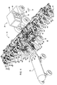
- FIG. 1 is a perspective view of an agricultural implement according to one embodiment.
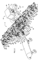
- FIG. 2 is a perspective view of an agricultural implement according to another embodiment.
- FIGS. 1 and 2 illustrate an agricultural implement 10 for applying a matter (e.g., anhydrous ammonia) to a soil (not shown).
- the illustrated agricultural implement 10 includes a coupling mechanism 15 for coupling to a vehicle 20 and a tank 22.
- a frame 25 is coupled to the coupling mechanism 15.
- the frame 25 extends rearwardly from the coupling mechanism 15 in a direction opposite of a direction of travel 30.
- a plurality of wheel assemblies 35 are coupled to the frame 25.
- the wheel assemblies 35 support the frame 25 above a surface 40.
- a first ground engaging component 45 is coupled to the frame 25.
- a second ground engaging component 50 is coupled to the frame 25.
- a third ground engaging component 55 is coupled to the frame 25.
- Additional ground engaging components 60 are also coupled to the frame 25.
- the illustrated agricultural implement 10 includes a flow monitor 65.
- the illustrated flow monitor 65 includes a first temperature sensing device 70 positioned adjacent the first ground engaging component 45.
- a second temperature sensing device 75 is positioned adjacent the second ground engaging component 50.
- a third temperature sensing device 80 is positioned adjacent the third ground engaging component 55.
- Additional temperature sensing devices 85 are positioned adjacent the additional ground engaging components 60.
- the flow monitor 65 includes a display device 90 having a signaling device 95. Referring to FIG. 1 , the display device 90 or signaling device 95 may be a monitor 100 coupled to the vehicle 20. Alternatively, the display device 90 may be a computer 105 ( FIG. 2 ).
- the coupling mechanism 15 is coupled to the vehicle 20. While the vehicle 20 moves in the direction of travel 30, the first, second, third, and additional ground engaging components (45, 50, 55, 60) apply the matter to the soil through a first, second, third, and additional flow paths (110, 115, 120, 125) having a first, second, third, and additional outlets (130, 135, 140, 145).
- the first, second, third, and additional temperature sensing devices (70, 75, 80, 85) produce a first, second, third, and additional temperature signals (not shown).
- the first, second, third, and additional temperature signals are received and displayed by the display device 90.
- the first, second, third, and additional temperature signals may be a first, second, third, and additional wireless signal (not shown).
- the display device 90 may be the computer 105 that receives the first, second, third, and additional wireless signals.
- the display device 90 is activated when the first, second, third, and additional temperature signals differ by a predetermined value. Activation of the signaling device 95 may produce a visual signal (not shown) that is displayed on the display device 90, or an audible signal (not shown), or both.
Landscapes
- Life Sciences & Earth Sciences (AREA)
- Soil Sciences (AREA)
- Environmental Sciences (AREA)
- Engineering & Computer Science (AREA)
- Water Supply & Treatment (AREA)
- Arrangements For Transmission Of Measured Signals (AREA)
- Management, Administration, Business Operations System, And Electronic Commerce (AREA)
Abstract
Description
- The present disclosure generally relates to a flow monitor for monitoring application of a matter through a first flow path having a first outlet and a second flow path having a second outlet. The invention further relates to an agricultural implement with such flow monitor.
- Flow monitors can be used to monitor flow of a chemical through a pipe to indicate if the pipe becomes obstructed or blocked. For example, the flow of a chemical being applied to soil by an agricultural implement can become reduced or stopped if distribution lines become clogged or broken. In order to monitor the flow of chemical application by an agricultural implement, agricultural implements commonly include control valves with flow sensors positioned upstream of the distribution lines.
U.S. Patent No. 4,458,609 discloses such a device including a heat exchanger that maintains anhydrous ammonia in a liquid state so that a flow control valve can accurately control the flow rate of ammonia to a manifold. Separate lines connected to the manifold downstream of the control valve distribute the ammonia to nozzles associated with earthworking tools to place the ammonia into the soil. - Other flow monitors include pressure gauges positioned upstream of distribution lines.
U.S. Patent Publication No. 2010/0073473 discloses a pressure gauge that is used to monitor pressure at a distributor. A camera is positioned to view the pressure gauge and to transmit and image of the pressure gauge to a monitor in an operator cab of a tractor pulling the implement. Separate distribution lines connected to the distributor disperse the ammonia to nozzles associated with earthworking tools to place the ammonia into the soil. - One object of the invention is to provide an alternative flow monitoring device for an agricultural implement in order to lower costs and complexity.
- The object will be achieved by the teaching of the claims 1 and 9. Further advantageous embodiments are described within the accompanying claims.
- Accordingly, a flow monitor of the above mentioned manner is provided with a first temperature sensing device positioned adjacent the first outlet and producing a first temperature signal, a second temperature sensing device is positioned adjacent the second outlet and producing a second temperature signal. The flow monitor further comprising a signaling device, remote from the first outlet and remote from the second outlet, the signaling device is activated when the first temperature signal differs from the second temperature signal by a predetermined value.
- The flow monitor is for monitoring application of a matter through a first flow path having a first outlet and a second flow path having a second outlet. Such a flow monitor could be used in any type of spray device, mixing chamber, agricultural implement, chemical processing facility, etc. The matter could be a chemical such as anhydrous ammonia or any other liquid, solid, or gas. The flow monitor includes a first temperature sensing device positioned adjacent the first outlet. The first temperature sensing device may be a first thermocouple. The first temperature sensing device produces a first temperature signal. The first temperature signal may be a first wireless signal. A second temperature sensing device is positioned adjacent the second outlet. The second temperature sensing device may be a second thermocouple. The second temperature sensing device produces a second temperature signal. The second temperature signal may be a second wireless signal.
- A signaling device that is remote from the first outlet and remote from the second outlet is activated when the first temperature signal differs from the second temperature signal by a predetermined value. The first temperature signal may be indicative of a first flow path matter temperature and the second temperature signal may be indicative of an ambient temperature. Alternatively, the second temperature signal may be indicative of a second flow path matter temperature. The signaling device may be a monitor for displaying a visual signal. The signaling device or monitor may produce an audible signal. Alternatively, the signaling device may be a computer for displaying a visual signal. The computer may receive the first and second wireless signals. The computer may produce an audible or vibratory signal. The predetermined value may depend upon the matter, an initial temperature of the matter, and the ambient temperature among other things.
- In another embodiment, an agricultural implement for delivering a matter to a soil is disclosed. The agricultural implement includes a coupling mechanism for coupling to a vehicle. A frame is coupled to the coupling mechanism and extends from the coupling mechanism. The frame is adapted to be pulled by the vehicle in a direction of travel. A plurality of wheel assemblies is coupled to the frame. The wheel assemblies support the frame above a surface. A first, second, and third ground engaging component is coupled to the frame for delivering the matter to the soil. The agricultural implement includes a flow monitor. The flow monitor has a first temperature sensing device positioned adjacent the first ground engaging component. The first temperature sensing device may be a first thermocouple. The first temperature sensing device produces a first temperature signal. A second temperature sensing device is positioned adjacent the second ground engaging component. The second temperature sensing device may be a second thermocouple. The second temperature sensing device produces a second temperature signal. A third temperature sensing device is positioned adjacent the third ground engaging component. The third temperature sensing device may be a third thermocouple. The third temperature sensing device produces a third temperature signal. The flow monitor has a display device that is remote from the first, second, and third ground engaging components. The display device may display the first, second, and third temperature signals. The display device includes a signaling device that is activated when the first, second, and third temperature signals differ by a predetermined value. The display device or signaling device may be a monitor coupled to the vehicle. The monitor may display a first visual signal, produce a first audible signal, or both. Alternatively, the display device may be a computer. The computer may display a second visual signal, produce a second audible signal, or both. The signaling device may display a third visual signal, produce a third audible signal, or both. The predetermined value may depend upon the matter, an initial temperature of the matter, and an ambient temperature among other things.
- In yet another embodiment, a flow monitor is disclosed. The flow monitor is for monitoring application of a matter by an agricultural implement adapted to be pulled by a vehicle. The agricultural implement includes a flow path having an outlet. The flow monitor includes a first temperature sensing device positioned adjacent the outlet that produces a matter temperature signal. The first temperature sensing device may be a first thermocouple. A second temperature sensing device is coupled to one of the agricultural implement and the vehicle and produces an ambient temperature signal. The second temperature sensing device may be a second thermocouple. A signaling device that is remote from the outlet is activated when the matter temperature signal differs from the ambient temperature signal by a predetermined value. The predetermined value may depend upon the matter, an initial temperature of the matter, and the ambient temperature among other things.
-
FIG. 1 is a perspective view of an agricultural implement according to one embodiment. -
FIG. 2 is a perspective view of an agricultural implement according to another embodiment. - Before any embodiments are explained in detail, it is to be understood that the disclosure is not limited in its application to the details of construction and the arrangement of components set forth in the following description or illustrated in the following drawings. The disclosure is capable of other embodiments and of being practiced or of being carried out in various ways.
-
FIGS. 1 and2 illustrate an agricultural implement 10 for applying a matter (e.g., anhydrous ammonia) to a soil (not shown). The illustrated agricultural implement 10 includes a coupling mechanism 15 for coupling to avehicle 20 and atank 22. - A frame 25 is coupled to the coupling mechanism 15. The frame 25 extends rearwardly from the coupling mechanism 15 in a direction opposite of a direction of
travel 30. A plurality ofwheel assemblies 35 are coupled to the frame 25. Thewheel assemblies 35 support the frame 25 above asurface 40. - A first
ground engaging component 45 is coupled to the frame 25. A secondground engaging component 50 is coupled to the frame 25. A thirdground engaging component 55 is coupled to the frame 25. Additionalground engaging components 60 are also coupled to the frame 25. - The illustrated agricultural implement 10 includes a
flow monitor 65. The illustrated flow monitor 65 includes a firsttemperature sensing device 70 positioned adjacent the firstground engaging component 45. A secondtemperature sensing device 75 is positioned adjacent the secondground engaging component 50. A thirdtemperature sensing device 80 is positioned adjacent the thirdground engaging component 55. Additionaltemperature sensing devices 85 are positioned adjacent the additionalground engaging components 60. The flow monitor 65 includes adisplay device 90 having a signalingdevice 95. Referring toFIG. 1 , thedisplay device 90 or signalingdevice 95 may be amonitor 100 coupled to thevehicle 20. Alternatively, thedisplay device 90 may be a computer 105 (FIG. 2 ). - In operation, the coupling mechanism 15 is coupled to the
vehicle 20. While thevehicle 20 moves in the direction oftravel 30, the first, second, third, and additional ground engaging components (45, 50, 55, 60) apply the matter to the soil through a first, second, third, and additional flow paths (110, 115, 120, 125) having a first, second, third, and additional outlets (130, 135, 140, 145). The first, second, third, and additional temperature sensing devices (70, 75, 80, 85) produce a first, second, third, and additional temperature signals (not shown). The first, second, third, and additional temperature signals are received and displayed by thedisplay device 90. The first, second, third, and additional temperature signals may be a first, second, third, and additional wireless signal (not shown). Thedisplay device 90 may be thecomputer 105 that receives the first, second, third, and additional wireless signals. Thedisplay device 90 is activated when the first, second, third, and additional temperature signals differ by a predetermined value. Activation of thesignaling device 95 may produce a visual signal (not shown) that is displayed on thedisplay device 90, or an audible signal (not shown), or both. - While the disclosure has been illustrated and described in detail in the drawinqs and foregoing description, such illustration and description is to be considered as exemplary and not restrictive in character, it being understood that illustrative embodiments have been shown and described and that all changes and modifications that come within the spirit of the disclosure are desired to be protected. It will be noted that alternative embodiments of the present disclosure may not include all of the features described yet still benefit from at least some of the advantages of such features. Those of ordinary skill in the art may readily devise their own implementations that incorporate one or more of the features of the present disclosure and fall within the spirit and scope of the present invention as defined by the appended claims.
Claims (14)
- A flow monitor (65) for monitoring application of a matter through a first flow path (110) having a first outlet (130) and a second flow path (115) having a second outlet (135), characterized in further comprising:a first temperature sensing device (70) positioned adjacent the first outlet (130) and producing a first temperature signal;a second temperature sensing device (75) positioned adjacent the second outlet (135) and producing a second temperature signal; anda signaling device (95), remote from the first outlet (130) and remote from the second outlet (135), the signaling device (95) is activated when the first temperature signal differs from the second temperature signal by a predetermined value.
- The flow monitor (65) of claim 1, wherein the first temperature signal is indicative of a first flow path (110) matter temperature and the second temperature signal is indicative of an ambient temperature.
- The flow monitor (65) of claim 1 or 2, wherein the first temperature signal is indicative of a first flow path (110) matter temperature and the second temperature signal is indicative of a second flow path (115) matter temperature.
- The flow monitor (65) of one of the claims 1 to 3, wherein the signaling device (95) is a monitor (100) for displaying a visual signal.
- The flow monitor (65) of one of the claims 1 to 4, wherein the signaling device (95) produces an audible signal.
- The flow monitor (65) of one of the claims 1 to 5, wherein the signaling device (95) is a computer (105) for displaying a visual signal and the first temperature signal is a first wireless signal received by the computer (105) and the second temperature signal is a second wireless signal received by the computer (105).
- The flow monitor (65) of one of the claims 1 to 6, wherein the matter is anhydrous ammonia.
- The flow monitor (65) of one of the claims 1 to 7, wherein the first temperature sensing device (70) is a first thermocouple and the second temperature sensing device (75) is a second thermocouple.
- An agricultural implement (10) adapted to be pulled by a vehicle (20), the agricultural implement (10) comprising a flow monitor (65) according to one of the claims 1 to 8.
- An agricultural implement (10) according to claim 9, further comprising, a first ground engaging component (45) for delivering the matter to the soil, and a second ground engaging component (50) for delivering the matter to the soil, wherein the first temperature sensing device (70) is positioned adjacent the first ground engaging component (45) and the second temperature sensing device (75) is positioned adjacent the second ground engaging component (50).
- An agricultural implement (10) of claim 9 or 10, further comprising a coupling mechanism (15) for coupling to a vehicle (20);
a frame (25) coupled to the coupling mechanism (15) and extending from the coupling mechanism (15) and adapted to be pulled by the vehicle (20) in a direction of travel (30);
a plurality of wheel assemblies (35) coupled to the frame (25), the wheel assemblies (35) supporting the frame (25) above a surface (40);
and a display device (90), remote from the first ground engaging component (45) and remote from the second ground engaging component (50), the display device (90) displaying the first temperature signal and the second temperature signal;
wherein the display device (90) comprises the signaling device (95) that is activated when the first temperature signal and the second temperature signal differ by a predetermined value. - The agricultural implement (10) of claim 11, wherein activation of the signaling device (95) produces a visual signal displayed on the display device (90).
- The agricultural implement (10) of claim 11 or 12, further comprising a third ground engaging component (55) coupled to the frame (25) for delivering the matter to the soil and a third temperature sensing device (80) positioned adjacent the third ground engaging component (55) and producing a third temperature signal, the display device (90) is activated when the first temperature signal, the second temperature signal, and the third temperature signal differ by a predetermined value.
- The agricultural implement (10) of claim 13, wherein the first temperature sensing device (70) is a first thermocouple, the second temperature sensing device (75) is a second thermocouple, and the third temperature sensing device (80) is a third thermocouple.
Applications Claiming Priority (1)
| Application Number | Priority Date | Filing Date | Title |
|---|---|---|---|
| US13/273,275 US20130093580A1 (en) | 2011-10-14 | 2011-10-14 | Flow monitor for matter in a flow path |
Publications (1)
| Publication Number | Publication Date |
|---|---|
| EP2580952A1 true EP2580952A1 (en) | 2013-04-17 |
Family
ID=47137514
Family Applications (1)
| Application Number | Title | Priority Date | Filing Date |
|---|---|---|---|
| EP12186810.3A Withdrawn EP2580952A1 (en) | 2011-10-14 | 2012-10-01 | A flow monitor and agricultural implement with such |
Country Status (3)
| Country | Link |
|---|---|
| US (1) | US20130093580A1 (en) |
| EP (1) | EP2580952A1 (en) |
| CN (1) | CN103048018A (en) |
Cited By (1)
| Publication number | Priority date | Publication date | Assignee | Title |
|---|---|---|---|---|
| CN103548444A (en) * | 2013-10-18 | 2014-02-05 | 中国水稻研究所 | Device for quantitatively detecting influence of ammonia released from soil on seed germination |
Families Citing this family (5)
| Publication number | Priority date | Publication date | Assignee | Title |
|---|---|---|---|---|
| LT2966964T (en) * | 2013-03-14 | 2018-08-27 | Precision Planting Llc | Systems for agricultural implement trench depth control and soil monitoring |
| US10785905B2 (en) | 2014-05-08 | 2020-09-29 | Precision Planting Llc | Liquid application apparatus comprising a seed firmer |
| UA120613C2 (en) * | 2014-05-08 | 2020-01-10 | Зе Клаймат Корпорейшн | Systems, methods, and apparatus for soil and seed monitoring |
| US10561059B2 (en) | 2015-06-15 | 2020-02-18 | Precision Planting Llc | Systems, methods, and apparatus for agricultural liquid application |
| CN111386031A (en) | 2017-10-02 | 2020-07-07 | 精密种植有限责任公司 | Systems and equipment for soil and seed monitoring |
Citations (6)
| Publication number | Priority date | Publication date | Assignee | Title |
|---|---|---|---|---|
| US4458609A (en) | 1982-03-05 | 1984-07-10 | Tofte David S | Method and apparatus for controlling and monitoring NH3 |
| WO1998037751A1 (en) * | 1997-02-28 | 1998-09-03 | Capstan Ag Systems, Inc. | System and process for applying ammonia to soil |
| US6003534A (en) * | 1996-02-12 | 1999-12-21 | The Minister Of Agriculture For The State Of New South Wales | Anhydrous ammonia distributor |
| US6067917A (en) * | 1998-05-29 | 2000-05-30 | Pgi International, Ltd. | Method and apparatus for flow control of NH3 |
| WO2007007093A2 (en) * | 2005-07-12 | 2007-01-18 | Alexander Terrell | Liquid flow control apparatus |
| US20100073473A1 (en) | 2008-09-22 | 2010-03-25 | Nimberger Spencer M | Nh3 distributor monitoring system and method |
Family Cites Families (6)
| Publication number | Priority date | Publication date | Assignee | Title |
|---|---|---|---|---|
| US5574657A (en) * | 1994-02-08 | 1996-11-12 | Micro-Trak Systems, Inc. | Electronic rate meter controller and method |
| US7313946B2 (en) * | 2004-07-15 | 2008-01-01 | Matsuo Electric Co., Ltd. | Moisture detector |
| US7502665B2 (en) * | 2005-05-23 | 2009-03-10 | Capstan Ag Systems, Inc. | Networked diagnostic and control system for dispensing apparatus |
| AU2007322074A1 (en) * | 2006-11-20 | 2008-05-29 | Water Optimizer L.L.C. | Control system |
| CA2674527C (en) * | 2008-08-01 | 2015-09-01 | Capstan Ag Systems, Inc. | A method and system to control flow from individual nozzles while controlling overall system flow and pressure |
| US8727032B2 (en) * | 2011-01-10 | 2014-05-20 | Cnh Industrial Canada, Ltd. | Implement with tool bar behind wing frames |
-
2011
- 2011-10-14 US US13/273,275 patent/US20130093580A1/en not_active Abandoned
-
2012
- 2012-10-01 EP EP12186810.3A patent/EP2580952A1/en not_active Withdrawn
- 2012-10-15 CN CN2012103902592A patent/CN103048018A/en active Pending
Patent Citations (6)
| Publication number | Priority date | Publication date | Assignee | Title |
|---|---|---|---|---|
| US4458609A (en) | 1982-03-05 | 1984-07-10 | Tofte David S | Method and apparatus for controlling and monitoring NH3 |
| US6003534A (en) * | 1996-02-12 | 1999-12-21 | The Minister Of Agriculture For The State Of New South Wales | Anhydrous ammonia distributor |
| WO1998037751A1 (en) * | 1997-02-28 | 1998-09-03 | Capstan Ag Systems, Inc. | System and process for applying ammonia to soil |
| US6067917A (en) * | 1998-05-29 | 2000-05-30 | Pgi International, Ltd. | Method and apparatus for flow control of NH3 |
| WO2007007093A2 (en) * | 2005-07-12 | 2007-01-18 | Alexander Terrell | Liquid flow control apparatus |
| US20100073473A1 (en) | 2008-09-22 | 2010-03-25 | Nimberger Spencer M | Nh3 distributor monitoring system and method |
Cited By (1)
| Publication number | Priority date | Publication date | Assignee | Title |
|---|---|---|---|---|
| CN103548444A (en) * | 2013-10-18 | 2014-02-05 | 中国水稻研究所 | Device for quantitatively detecting influence of ammonia released from soil on seed germination |
Also Published As
| Publication number | Publication date |
|---|---|
| CN103048018A (en) | 2013-04-17 |
| US20130093580A1 (en) | 2013-04-18 |
Similar Documents
| Publication | Publication Date | Title |
|---|---|---|
| US20130093580A1 (en) | Flow monitor for matter in a flow path | |
| US20130008361A1 (en) | Liquid fertilizer sensor system | |
| US8833680B2 (en) | Method and apparatus for detecting a plugged nozzle of a sprayer | |
| US10209111B2 (en) | Device and method for detecting blockages in an agricultural sprayer | |
| US9259745B2 (en) | NH3 fault and distribution variance detection system | |
| US9232687B2 (en) | Agricultural systems | |
| US8928486B2 (en) | Pressure-based blockage detection system and method in crop production systems | |
| US20170086363A1 (en) | Agricultural liquid fertilizer and chemical delivery system and method of use | |
| US20160128270A1 (en) | System for monitoring and controlling product distribution in an agricultural system | |
| US20090112372A1 (en) | Adaptive feedback sources for application controllers | |
| US9324197B2 (en) | Method and system for managing the hand-off between control terminals | |
| US20250160236A1 (en) | Agricultural systems | |
| CA2939273C (en) | Systems and methods for air cart pressurization monitoring | |
| CA2964322A1 (en) | System for dispensing seeds and treatment | |
| EP2966966A1 (en) | Vehicle control and gateway module | |
| EP2570027B1 (en) | Multi-nozzle body for an agricultural field spraying device | |
| CA3214314A1 (en) | Systems, methods, and apparatus for agricultural liquid application | |
| US8564658B2 (en) | NH3 distributor monitoring system and method | |
| CA2944423A1 (en) | Method and system for managing the hand-off between control terminals | |
| US11054292B2 (en) | Material flow monitoring system and method | |
| US10920805B2 (en) | System and method for detecting a connector failure in an agricultural apparatus | |
| US20160345489A1 (en) | Anhydrous Ammonia Fertilizer Apparatus Monitor | |
| US20100319794A1 (en) | Hose bend bleeder for ammonia application system | |
| DE102004025758A1 (en) | Commodity e.g. seed, distribution machine e.g. seeder, for use with tractor, has electronic controller to automatically adjust rotational speed of hydraulic motor of blower through hydraulic valve based on type and quantity of commodity | |
| DE102021132471A9 (en) | Agricultural soil cultivation device with dispensing devices for dispensing an output medium |
Legal Events
| Date | Code | Title | Description |
|---|---|---|---|
| PUAI | Public reference made under article 153(3) epc to a published international application that has entered the european phase |
Free format text: ORIGINAL CODE: 0009012 |
|
| AK | Designated contracting states |
Kind code of ref document: A1 Designated state(s): AL AT BE BG CH CY CZ DE DK EE ES FI FR GB GR HR HU IE IS IT LI LT LU LV MC MK MT NL NO PL PT RO RS SE SI SK SM TR |
|
| AX | Request for extension of the european patent |
Extension state: BA ME |
|
| 17P | Request for examination filed |
Effective date: 20131017 |
|
| RBV | Designated contracting states (corrected) |
Designated state(s): AL AT BE BG CH CY CZ DE DK EE ES FI FR GB GR HR HU IE IS IT LI LT LU LV MC MK MT NL NO PL PT RO RS SE SI SK SM TR |
|
| STAA | Information on the status of an ep patent application or granted ep patent |
Free format text: STATUS: THE APPLICATION HAS BEEN WITHDRAWN |
|
| RIC1 | Information provided on ipc code assigned before grant |
Ipc: A01C 23/02 20060101ALI20141029BHEP Ipc: A01C 21/00 20060101ALI20141029BHEP Ipc: A01C 23/00 20060101AFI20141029BHEP |
|
| 18W | Application withdrawn |
Effective date: 20141031 |