EP2580440B1 - Abgasbehandlungsvorrichtung - Google Patents
Abgasbehandlungsvorrichtung Download PDFInfo
- Publication number
- EP2580440B1 EP2580440B1 EP11721328.0A EP11721328A EP2580440B1 EP 2580440 B1 EP2580440 B1 EP 2580440B1 EP 11721328 A EP11721328 A EP 11721328A EP 2580440 B1 EP2580440 B1 EP 2580440B1
- Authority
- EP
- European Patent Office
- Prior art keywords
- exhaust gas
- gas treatment
- perforation
- tube
- treatment device
- Prior art date
- Legal status (The legal status is an assumption and is not a legal conclusion. Google has not performed a legal analysis and makes no representation as to the accuracy of the status listed.)
- Revoked
Links
Images


Classifications
-
- F—MECHANICAL ENGINEERING; LIGHTING; HEATING; WEAPONS; BLASTING
- F02—COMBUSTION ENGINES; HOT-GAS OR COMBUSTION-PRODUCT ENGINE PLANTS
- F02C—GAS-TURBINE PLANTS; AIR INTAKES FOR JET-PROPULSION PLANTS; CONTROLLING FUEL SUPPLY IN AIR-BREATHING JET-PROPULSION PLANTS
- F02C7/00—Features, components parts, details or accessories, not provided for in, or of interest apart form groups F02C1/00 - F02C6/00; Air intakes for jet-propulsion plants
-
- F—MECHANICAL ENGINEERING; LIGHTING; HEATING; WEAPONS; BLASTING
- F01—MACHINES OR ENGINES IN GENERAL; ENGINE PLANTS IN GENERAL; STEAM ENGINES
- F01N—GAS-FLOW SILENCERS OR EXHAUST APPARATUS FOR MACHINES OR ENGINES IN GENERAL; GAS-FLOW SILENCERS OR EXHAUST APPARATUS FOR INTERNAL-COMBUSTION ENGINES
- F01N3/00—Exhaust or silencing apparatus having means for purifying, rendering innocuous, or otherwise treating exhaust
- F01N3/08—Exhaust or silencing apparatus having means for purifying, rendering innocuous, or otherwise treating exhaust for rendering innocuous
- F01N3/10—Exhaust or silencing apparatus having means for purifying, rendering innocuous, or otherwise treating exhaust for rendering innocuous by thermal or catalytic conversion of noxious components of exhaust
- F01N3/24—Exhaust or silencing apparatus having means for purifying, rendering innocuous, or otherwise treating exhaust for rendering innocuous by thermal or catalytic conversion of noxious components of exhaust characterised by constructional aspects of converting apparatus
- F01N3/28—Construction of catalytic reactors
- F01N3/2892—Exhaust flow directors or the like, e.g. upstream of catalytic device
-
- F—MECHANICAL ENGINEERING; LIGHTING; HEATING; WEAPONS; BLASTING
- F01—MACHINES OR ENGINES IN GENERAL; ENGINE PLANTS IN GENERAL; STEAM ENGINES
- F01N—GAS-FLOW SILENCERS OR EXHAUST APPARATUS FOR MACHINES OR ENGINES IN GENERAL; GAS-FLOW SILENCERS OR EXHAUST APPARATUS FOR INTERNAL-COMBUSTION ENGINES
- F01N13/00—Exhaust or silencing apparatus characterised by constructional features
- F01N13/009—Exhaust or silencing apparatus characterised by constructional features having two or more separate purifying devices arranged in series
- F01N13/0093—Exhaust or silencing apparatus characterised by constructional features having two or more separate purifying devices arranged in series the purifying devices are of the same type
-
- F—MECHANICAL ENGINEERING; LIGHTING; HEATING; WEAPONS; BLASTING
- F01—MACHINES OR ENGINES IN GENERAL; ENGINE PLANTS IN GENERAL; STEAM ENGINES
- F01N—GAS-FLOW SILENCERS OR EXHAUST APPARATUS FOR MACHINES OR ENGINES IN GENERAL; GAS-FLOW SILENCERS OR EXHAUST APPARATUS FOR INTERNAL-COMBUSTION ENGINES
- F01N13/00—Exhaust or silencing apparatus characterised by constructional features
- F01N13/009—Exhaust or silencing apparatus characterised by constructional features having two or more separate purifying devices arranged in series
- F01N13/0097—Exhaust or silencing apparatus characterised by constructional features having two or more separate purifying devices arranged in series the purifying devices are arranged in a single housing
-
- F—MECHANICAL ENGINEERING; LIGHTING; HEATING; WEAPONS; BLASTING
- F01—MACHINES OR ENGINES IN GENERAL; ENGINE PLANTS IN GENERAL; STEAM ENGINES
- F01N—GAS-FLOW SILENCERS OR EXHAUST APPARATUS FOR MACHINES OR ENGINES IN GENERAL; GAS-FLOW SILENCERS OR EXHAUST APPARATUS FOR INTERNAL-COMBUSTION ENGINES
- F01N2470/00—Structure or shape of exhaust gas passages, pipes or tubes
- F01N2470/02—Tubes being perforated
- F01N2470/04—Tubes being perforated characterised by shape, disposition or dimensions of apertures
-
- F—MECHANICAL ENGINEERING; LIGHTING; HEATING; WEAPONS; BLASTING
- F01—MACHINES OR ENGINES IN GENERAL; ENGINE PLANTS IN GENERAL; STEAM ENGINES
- F01N—GAS-FLOW SILENCERS OR EXHAUST APPARATUS FOR MACHINES OR ENGINES IN GENERAL; GAS-FLOW SILENCERS OR EXHAUST APPARATUS FOR INTERNAL-COMBUSTION ENGINES
- F01N2470/00—Structure or shape of exhaust gas passages, pipes or tubes
- F01N2470/18—Structure or shape of exhaust gas passages, pipes or tubes the axis of inlet or outlet tubes being other than the longitudinal axis of apparatus
-
- F—MECHANICAL ENGINEERING; LIGHTING; HEATING; WEAPONS; BLASTING
- F01—MACHINES OR ENGINES IN GENERAL; ENGINE PLANTS IN GENERAL; STEAM ENGINES
- F01N—GAS-FLOW SILENCERS OR EXHAUST APPARATUS FOR MACHINES OR ENGINES IN GENERAL; GAS-FLOW SILENCERS OR EXHAUST APPARATUS FOR INTERNAL-COMBUSTION ENGINES
- F01N2470/00—Structure or shape of exhaust gas passages, pipes or tubes
- F01N2470/20—Dimensional characteristics of tubes, e.g. length, diameter
-
- F—MECHANICAL ENGINEERING; LIGHTING; HEATING; WEAPONS; BLASTING
- F01—MACHINES OR ENGINES IN GENERAL; ENGINE PLANTS IN GENERAL; STEAM ENGINES
- F01N—GAS-FLOW SILENCERS OR EXHAUST APPARATUS FOR MACHINES OR ENGINES IN GENERAL; GAS-FLOW SILENCERS OR EXHAUST APPARATUS FOR INTERNAL-COMBUSTION ENGINES
- F01N3/00—Exhaust or silencing apparatus having means for purifying, rendering innocuous, or otherwise treating exhaust
- F01N3/08—Exhaust or silencing apparatus having means for purifying, rendering innocuous, or otherwise treating exhaust for rendering innocuous
- F01N3/10—Exhaust or silencing apparatus having means for purifying, rendering innocuous, or otherwise treating exhaust for rendering innocuous by thermal or catalytic conversion of noxious components of exhaust
- F01N3/18—Exhaust or silencing apparatus having means for purifying, rendering innocuous, or otherwise treating exhaust for rendering innocuous by thermal or catalytic conversion of noxious components of exhaust characterised by methods of operation; Control
- F01N3/20—Exhaust or silencing apparatus having means for purifying, rendering innocuous, or otherwise treating exhaust for rendering innocuous by thermal or catalytic conversion of noxious components of exhaust characterised by methods of operation; Control specially adapted for catalytic conversion
- F01N3/206—Adding periodically or continuously substances to exhaust gases for promoting purification, e.g. catalytic material in liquid form, NOx reducing agents
- F01N3/2066—Selective catalytic reduction [SCR]
-
- Y—GENERAL TAGGING OF NEW TECHNOLOGICAL DEVELOPMENTS; GENERAL TAGGING OF CROSS-SECTIONAL TECHNOLOGIES SPANNING OVER SEVERAL SECTIONS OF THE IPC; TECHNICAL SUBJECTS COVERED BY FORMER USPC CROSS-REFERENCE ART COLLECTIONS [XRACs] AND DIGESTS
- Y02—TECHNOLOGIES OR APPLICATIONS FOR MITIGATION OR ADAPTATION AGAINST CLIMATE CHANGE
- Y02T—CLIMATE CHANGE MITIGATION TECHNOLOGIES RELATED TO TRANSPORTATION
- Y02T10/00—Road transport of goods or passengers
- Y02T10/10—Internal combustion engine [ICE] based vehicles
- Y02T10/12—Improving ICE efficiencies
-
- Y—GENERAL TAGGING OF NEW TECHNOLOGICAL DEVELOPMENTS; GENERAL TAGGING OF CROSS-SECTIONAL TECHNOLOGIES SPANNING OVER SEVERAL SECTIONS OF THE IPC; TECHNICAL SUBJECTS COVERED BY FORMER USPC CROSS-REFERENCE ART COLLECTIONS [XRACs] AND DIGESTS
- Y10—TECHNICAL SUBJECTS COVERED BY FORMER USPC
- Y10T—TECHNICAL SUBJECTS COVERED BY FORMER US CLASSIFICATION
- Y10T137/00—Fluid handling
- Y10T137/8593—Systems
-
- Y—GENERAL TAGGING OF NEW TECHNOLOGICAL DEVELOPMENTS; GENERAL TAGGING OF CROSS-SECTIONAL TECHNOLOGIES SPANNING OVER SEVERAL SECTIONS OF THE IPC; TECHNICAL SUBJECTS COVERED BY FORMER USPC CROSS-REFERENCE ART COLLECTIONS [XRACs] AND DIGESTS
- Y10—TECHNICAL SUBJECTS COVERED BY FORMER USPC
- Y10T—TECHNICAL SUBJECTS COVERED BY FORMER US CLASSIFICATION
- Y10T29/00—Metal working
- Y10T29/49—Method of mechanical manufacture
- Y10T29/49764—Method of mechanical manufacture with testing or indicating
Definitions
- the invention relates to an exhaust gas treatment device with which the exhaust gases of an internal combustion engine can be cleaned.
- the invention relates to an exhaust treatment device for the so-called off-highway area, ie z.
- an exhaust treatment device for a watercraft or a rail vehicle As an exhaust treatment device for a watercraft or a rail vehicle.
- the engine power used in watercraft and especially yachts has a very wide range.
- the engine power ranges for example from about 250 kW [kilowatts] in yachts with about 10 m in length to engine outputs of well over 1,000 kW [kilowatts] for yachts up to more than 100 m in length.
- the design and shape of the engine compartments of such vessels varies even from the same model often from vehicle to vehicle, because many individual Needs of the buyer must be considered. This also affects the development of the emission control systems, which must adapt to the respective conditions. Therefore, it is also transferred to use modular catalyst systems whose application for a particular vessel can be carried out quickly and without much additional development work.
- GRP structures glass fiber reinforced plastics
- CFRP structures carbon fiber reinforced plastics
- An exhaust gas purification system which has an inlet chamber through which an inlet pipe extends.
- the inlet tube has a plurality of openings through which exhaust gas from the inlet tube can pass into the inlet chamber.
- the openings are distributed over the circumference of the inlet tube and over the length of the inlet tube.
- resistance plates are arranged in the inflow pipe, which influence the flow of the exhaust gas in the inflow pipe.
- an exhaust treatment device is to be described, which is particularly suitable for a watercraft.
- a method for producing a tube for such an exhaust gas treatment device will be described.
- the invention relates to an exhaust gas treatment device comprising a housing having a cross-sectional area and a first wall, wherein at least one tube with a second wall extends through the first wall and the second wall has a perforation.
- a pipe is understood in particular a flow line, which is preferably rigid. Although it should be sufficient for many applications to use a (metallic) cylindrical tube, this is not absolutely necessary. Thus, curved and / or (partially) flexible, tapered and / or expanding tubes may be provided.
- the at least one pipe accordingly has a perforation (multiplicity of pores, openings, holes,...), In particular following the entry into the exhaust-gas treatment device, which leads (at least in part) to a forced flow diversion of the exhaust gas.
- the flow of exhaust gas treatment components in the housing can be made uniform. In particular, it can be achieved that the exhaust gas flow on the exhaust gas treatment components has a higher uniformity index.
- v i are the local flow velocities. If possible, the local flow velocities used to calculate the uniform index are distributed as uniformly as possible over the cross-sectional area to be investigated.
- the exhaust gas treatment device when the tube has a first side and a second side and the perforation is only on the first side of the tube.
- one side of the tube is regularly meant a portion of the peripheral surface, with preferably the first side and the second side facing each other. It is further preferred that the peripheral surface of the tube is divided into exactly two (equal) sections, in which case the one side has no perforation and the other side has a perforation.
- the exhaust gas treatment device if at least one exhaust gas treatment component is arranged in the housing and the perforation is arranged only on a side facing away from the exhaust treatment component first side of the tube. It is further preferred that the perforation is designed so that the exhaust gas after exiting the perforations of a further flow deflection (eg., Due to the housing) performs and then particularly evenly supplied to the exhaust gas treatment component.
- the perforation should in particular be tuned so that immediately before entering the exhaust gas treatment component for the usual operating conditions predominantly high uniform index is achieved.
- the exhaust gas treatment component comprises a metallic honeycomb body and / or a carrier surface with catalytically active material and / or a particle deposition layer.
- a uniform flow through the exhaust particularly important so uniformly good cleaning results are achieved over the entire exhaust gas treatment component, and consequently particularly small exhaust treatment components for the initially described difficult installation situation can be used.
- the exhaust gas treatment device when the perforation is adapted to the cross-sectional area and / or shape of the housing.
- a similar adaptation can for example also be made to the shape, orientation, type of tube and / or the exhaust gas treatment components.
- the exhaust treatment device according to the invention may be implemented with an addition for an additive, wherein this addition of the additive can be operated with a controller, which is preferably implemented so that the system manages with a minimum number of input variables from the engine. It may be sufficient to obtain information about load and speed via the CAN bus of the internal combustion engine of the vessel.
- the exhaust gas treatment device according to the invention can also be operated so that information on the CAN bus of the engine of the watercraft is completely dispensed with. Then, a control or regulation of the exhaust gas treatment device according to the invention is carried out only with the information obtained from sensors in the exhaust treatment device and optionally with the signal of a arranged in the intake manifold of the internal combustion engine of the watercraft air mass sensor.
- the perforation of the tube is preferably formed by a plurality of openings or holes in the wall of the tube.
- the openings or holes may be shaped differently, for example in the manner of round holes, rectangles, squares, triangles or slots. However, it is preferred if the openings are shaped in the manner of round holes.
- the openings can be made by various manufacturing methods, such as drilling, punching, cutting or pressing.
- the method is particularly advantageous if, prior to step e), the total number of holes of the perforation is determined and in step e) a suitable distribution of the holes to the individual longitudinal sections of the tube is calculated.
- the first partial pressure loss is the pressure loss of the internal flow in the perforated tube.
- the second partial pressure loss is the pressure loss in the flow through the perforation and the third pressure loss is due to the internal flow in an antechamber in the housing before an exhaust treatment component.
- the first partial pressure loss and the third partial pressure loss are estimated by analytical relationships, for example via the pressure loss formula for the calculation of flows in straight tubes.
- the entire mass flow is now converted to a predetermined number of holes of the perforation. This results in a mass flow per hole.
- This mass flow is used to determine the hole size.
- the analytical pressure loss formula is used for passage through a pinhole, whereby a target pressure loss for the second partial pressure loss is given. From the target pressure loss for the second pressure loss and the predetermined number of holes, the required hole diameter is determined.
- the target pressure loss for the second pressure loss in the perfusion of the perforation is set so that the target pressure loss is the dominant pressure loss in the inflow into the exhaust treatment device.
- the target pressure loss is selected so that the target pressure loss and the second pressure loss is four times as large as the first pressure loss and the third pressure loss together.
- the flow distribution in the antechamber of the exhaust gas treatment device according to the invention can be influenced by the positioning of the holes on the longitudinal axis of the perforated tube.
- the cross-section of the exhaust treatment device along the tube is now divided into strip-shaped segments (side sections), each having a surface.
- the mass flow for each segment must be scaled directly with the area of the segment.
- the holes of the perforation are accordingly distributed according to the areas of the segments of the cross-sectional area.
- a uniform index of the flow of the exhaust gas treatment component in the exhaust gas treatment device of at least 0.9, preferably more than 0.95.
- a watercraft having at least one internal combustion engine and at least one exhaust gas treatment device according to the invention for cleaning the exhaust gases of the at least one internal combustion engine.
- FIG. 1 an exhaust gas treatment device 1 according to the invention is shown.
- the exhaust gas treatment device 1 has a housing 2 with a cross-sectional area 3 and a first wall 4.
- a cylindrical and metallic tube 5 extends through the first wall 4.
- the tube 5 forms an inlet 15 into the exhaust gas treatment device 1.
- the exhaust gas treatment device 1 has an outlet 16.
- the exhaust gas treatment device 1 is from the inlet 15 to the outlet 16 for an exhaust gas permeable, wherein the elements installed there have grown to the conditions prevailing there (high temperature resistant, corrosion resistant, etc).
- the flow through the exhaust gas treatment device 1 is indicated schematically by means of arrows. Starting from the inlet 15, an atrium 26 and a number of exhaust treatment components 10 are located one behind the other in the exhaust treatment device 1.
- the first exhaust treatment component 10 behind the pre-chamber 26 is a mixing element (eg a honeycomb body with a plurality of flow baffles for mixing the partial flows in adjacent ones) Channels), which serves to mix the exhaust gases.
- a hydrolysis catalyst 18 for reacting a reducing agent fed to the exhaust gas treatment device 1 upstream of the inlet 15.
- an SCR catalyst 20 is provided, which is divided here into two individual exhaust gas treatment components 10.
- the tube 5 extends at least partially into the prechamber 26 of the exhaust treatment device 1.
- a perforation 7 is provided so that exhaust gas entering through the inlet 15 can enter the prechamber 26.
- the tube 5 has a first side 8 and a second side 9.
- the first side 8 faces away from the first exhaust treatment component 10 in the exhaust treatment device 1.
- the second side 9 faces the first exhaust treatment component 10 in the exhaust treatment device 1.
- the perforation 7 is located only on the first side 8.
- the tube 5 has at the end lying in the housing 2 a closure 22, so that from the tube 5 in the pre-chamber 26 passing exhaust gas must flow through the perforation 7 of the tube 5.
- each of the perforation 7 of the tube 5 can be seen.
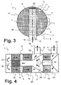
- the Fig. 2 and 3 have many common reference numerals, so that these figures are first explained together here.
- the first side 8 of the tube 5 can be seen in front of the first exhaust gas treatment component 10 in the exhaust gas treatment device 1.
- the tube 5 forms the inlet 15 in the exhaust gas treatment device 1 at the one end face and is closed at the opposite front end with the closure 22.
- the tube 5 has a perforation 7.
- the perforation 7 is adapted to the cross-sectional area 3 of the exhaust gas treatment device 1.
- the cross-sectional area 3 is divided into segments 11, while the tube 5 is divided into longitudinal sections 12.
- Each longitudinal section 12 can be assigned to a segment 11. The assignment results in the case shown here in that the tube 5 spans the cross-sectional area 3 in one direction and the segments 11 of the cross-sectional area 3 are respectively fixed perpendicular to the tube 5 and to the direction of the tube.
- the longitudinal sections 12 are then each the areas of the tube 5, which lie in certain segments 11.
- the perforation 7 is now adapted to the segments 11 in the individual longitudinal sections 12.
- the perforation 7 is in each case adapted to the surface of the segments 11.
- the perforation 7 is regularly formed by a plurality of holes 28. Also the holes 28 have an area.
- the total area of the holes 28 is in each case adapted to the surface of the segments 11.
- the total area of the holes 28 in each longitudinal section 12 is proportional to the area of the associated segment 11 Fig. 2 the number of holes 28, which form the perforation 7, adjusted in the individual longitudinal sections 12 of the tube 5.
- the size of the individual holes 28 of the perforation 7 is adjusted. This is an alternative for adjusting the number of holes. The adjustment of the number of holes and the adjustment of the size of the holes can also be combined within the scope of the invention.
- Fig. 4 shows a particular exhaust treatment device 1, which can be used particularly advantageously within an exhaust gas treatment system together with an exhaust gas treatment device 1 according to the invention. Nevertheless, such an exhaust gas treatment device 1 may possibly also be an invention independently of the design of the tube (eg without a perforation).
- This exhaust treatment device 1 also has a housing 2 with an inlet 15 for the exhaust gas of an internal combustion engine and a outlet 16 for purified exhaust gas.
- the exhaust treatment device 1 according to the Fig. 4 is traversed by the exhaust gas according to the arrows in the figure.
- the exhaust gas first flows through an annular exhaust gas treatment component 10.
- the exhaust gas is directed by a deflection region 29 into this exhaust gas treatment component 10.
- the first exhaust treatment component 10 is an oxidation catalyst 17.
- Within a cavity in the annular exhaust treatment component 10, a reducing agent supply 19 is provided.
- the exhaust gas treatment component 10 is adjoined by a renewed deflection region 29, through which the exhaust gas is directed into a tube 5.
- the reducing agent supply 19 now sprays (liquid) reducing agent (eg a urea-water solution) into the deflection region 29 behind the oxidation catalyst 17, so that there takes place a mixing, which in particular takes place the conical constriction is favored.
- the tube 5 extends through a plurality of further annular exhaust gas treatment components 10 into a further deflection region 29.
- a hydrolysis catalytic converter 18 is also provided in the tube, preferably concentrically with the last / first exhaust gas treatment components 10 opposite to the inlet 15. In the deflection region 29 behind the tube 5 the exhaust gas is deflected again, so that it passes the just mentioned further annular exhaust treatment components 10.
- the first further annular exhaust gas treatment component 10 in the flow direction is a particle separator 30, in particular a so-called open filter, which is formed with metallic corrugated sheets and metallic nonwovens.
- the metallic honeycomb structure preferably has a plurality of deflections, so that on the one hand a thorough mixing of the exhaust gas flow can be achieved again and on the other hand, the deposits of particles are favored by these deflections.
- the second further annular exhaust gas treatment component 10 forms an SCR catalytic converter 20.
- a renewed deflection region 29 follows, which now lines the cleaned exhaust gas in the direction of the outlet 16 of the exhaust gas treatment device Fig. 4 leads.
- the inlet 15 and the outlet 16 are each formed by a tube 5.
- tubes may extend at least partially through the wall 4 of the housing 2 of the exhaust treatment device 1. It is possible that the tubes 5 of inlet 15 and outlet 16 are also provided with a perforation according to the invention treated here. The same applies to the tube 5, which extends through the annular exhaust gas treatment components 10, wherein the perforation z. B. on the inlet 15 opposite region of the housing 2 is provided, which is formed by the last exhaust treatment components 10 projecting therethrough.
- an exhaust gas treatment system 27 which has a first module 23 and a second module 24.
- the exhaust gas firstly enters the first module 23, in order then to reach the second module 24 via an arbitrarily shaped connecting line 25 (which can also be designed as a tube).
- the flow of exhaust gas through the first module 23 and the second module 24 is indicated by arrows.
- the second module 24 is configured in a particularly advantageous manner as an exhaust gas treatment device 1 according to the invention with a tube 5 with a perforation 7. In this way, it can be achieved that the exhaust gas flow changed by the arbitrary guidance of the connecting line 25 is equalized on entering the second module 24 or is distributed uniformly over the cross-sectional area 3 of the second module 24.
- a reducing agent supply 19 (eg for a urea-water solution) is provided in the first module 23.
- a hydrolysis catalytic converter 18 and a (optionally coated) mixing element 21 may also be provided in the first module 23.
- the first module 23 leaves an exhaust gas flow, which is uniformly loaded with completely hydrolyzed and vaporized reducing agent (ammonia).
- the implementation of the pollutant components in the exhaust gas with the reducing agent is then carried out in the second module 24.
- This configuration can be achieved that the exhaust gas treatment system 27 can be adapted for a watercraft to the available space in the vessel.
- the connecting line 25 can be adapted individually.
- the connecting line is between 1 and 20 m long and is deflected over its entire length by more than 90 °, preferably more than 360 °.
- the guidance of the exhaust gas with the tube 5 with the perforation 7 makes it possible to at least partially equalize a possibly unequal exhaust gas flow due to the course of the connecting line 25.
- Fig. 6 shows a watercraft 13 having an internal combustion engine 14 and an exhaust gas treatment device 1 according to the invention for cleaning the exhaust gases of the internal combustion engine 14th
Landscapes
- Engineering & Computer Science (AREA)
- Chemical & Material Sciences (AREA)
- Combustion & Propulsion (AREA)
- Mechanical Engineering (AREA)
- General Engineering & Computer Science (AREA)
- Chemical Kinetics & Catalysis (AREA)
- Health & Medical Sciences (AREA)
- Toxicology (AREA)
- Exhaust Gas After Treatment (AREA)
Description
- Die Erfindung betrifft eine Abgasbehandlungsvorrichtung mit welcher die Abgase einer Verbrennungskraftmaschine gereinigt werden können. Insbesondere betrifft die Erfindung eine Abgasbehandlungsvorrichtung für den so genannten Off-Highway-Bereich, also z. B. eine Abgasbehandlungsvorrichtung für ein Wasserfahrzeug oder ein Schienenfahrzeug.
- Auch in diesen technischen Gebieten wird die Reinigung der Abgase von Verbrennungskraftmaschinen immer wichtiger. Im Bereich der Dieselmotoren, und insbesondere der unter Sauerstoffüberschuss betriebenen Dieselmotoren, kann die Abgasreinigung zumeist nur mit Hilfe moderner Abgasnachbehandlungstechnik realisiert werden. Beispielsweise wird zur effizienten Abgasreinigung hier auch das Verfahren der selektiven katalytischen Reduktion (SCR = selective catalytic reduction) angewendet, bei welchem dem Abgas ein Reduktionsmittel zur Reduktion von Stickstoffoxidverbindungen im Abgas zugeführt wird.
- Im Gegensatz zum Kraftfahrzeugmarkt, welcher durch hohe Stückzahlen und damit Großserienlösungen geprägt ist, werden im Off-Highway-Bereich, und insbesondere in dem Markt für Wasserfahrzeuge, vielfach individuelle, maßgeschneiderte Lösungen verlangt, weil die Stückzahlen erheblich geringer sind. Aus diesem Grund sind flexible Lösungen zur Reinigung der Abgase von Verbrennungskraftmaschinen für derartige Anwendungen besonders wichtig.
- Die in Wasserfahrzeugen und insbesondere Yachten verwendeten Motorleistungen weisen ein sehr großes Spektrum auf. Die Motorleistungen reichen zum Beispiel von ca. 250 kW [Kilowatt] bei Yachten mit ca. 10 m Länge bis hin zu Motorleistungen von weit mehr als 1.000 kW [Kilowatt] bei Yachten von bis zu mehr als 100 m Länge. Die Ausgestaltung und Form der Motorräume derartiger Wasserfahrzeuge variiert sogar bei demselben Modell oft von Fahrzeug zu Fahrzeug, weil vielfach individueller Bedürfnisse der Käufer berücksichtigt werden müssen. Davon ist auch die Entwicklung der Abgasreinigungsanlagen betroffen, die sich an die jeweiligen Bedingungen anpassen muss. Daher wird auch dazu übergegangen, modular aufgebaute Katalysatorsysteme einzusetzen, deren Applikation für ein bestimmtes Wasserfahrzeug schnell und ohne große zusätzliche Entwicklungsarbeit durchgeführt werden kann.
- Bei Einbauten in Maschinenräume von Wasserfahrzeugen müssen zum Teil sehr niedrige Oberflächentemperaturen eingehalten werden. Die Rümpfe von Wasserfahrzeugen sind teilweise aus GFK-Strukturen (glasfaserverstärkte Kunststoffe) oder CFK-Strukturen (kohlefaserverstärkte Kunststoffe) aufgebaut. Derartige Materialien können schon durch Temperaturen ab 120 °C irreparabel geschädigt werden, weil bestimmte Lösungsmittel in diesen Materialien bei derartigen Temperaturen ausdampfen. Bei Abgasbehandlungsvorrichtungen für Wasserfahrzeuge wie insbesondere Yachten ist daher eine besonders sichere Isolierung von heißen Bauteilen erforderlich. Des Weiteren muss für ausreichend Durchlüftung des Maschinenraumes und Umlüftung der gesamten Anlage gesorgt werden, ohne dass Hitzezentren zwischen Abgasanlage und Rumpf entstehen.
- Aus der
US 2003/0051449 A1 ist ist ein Abgasreinigunssystem bekannt, welches eine Einlasskammer aufweist durch die sich ein Einlassrohr erstreckt. Das Einlassrohr hat eine Vielzahl von Öffnungen durch welche Abgas aus dem Einlassrohr in die Einlasskammer übertreten kann. Die Öffnungen sind über den Umfang des Einlassrohres und über die Länge des Einlassrohres verteilt angeordnet. Zur Anpassung der Strömung, die durch die Öffnungen von dem Einströmrohr in die Einströmkammer übertritt, sind in dem Einströmrohr Widerstandsplatten angeordnet, die die Strömung des Abgases in dem Einströmrohr beeinflussen. - Ausgehend von dieser Ausgangssituation ist es Aufgabe der hier vorliegenden Erfindung, die geschilderten Probleme des Standes der Technik zumindest teilweise zu lösen. Insbesondere soll eine Abgasbehandlungsvorrichtung beschrieben werden, die für ein Wasserfahrzeug besonders geeignet ist. Darüber hinaus soll ein Verfahren zur Herstellung eines Rohres für eine solche Abgasbehandlungsvorrichtung beschrieben werden.
- Diese Aufgaben werden gelöst durch die Abgasbehandlungsvorrichtung gemäß den Merkmalen des Anspruches 1 und durch ein Verfahren gemäß den Merkmalen des Anspruches 8. Weitere vorteilhafte Ausgestaltungen sind Gegenstand der jeweils abhängigen Ansprüche. Die dort angegebenen Merkmale können beliebig miteinander kombiniert werden. Die Beschreibung, insbesondere im Zusammenhang mit den Figuren, gibt weitere Ausführungsbeispiele an.
- Die Erfindung betrifft eine Abgasbehandlungsvorrichtung aufweisend ein Gehäuse mit einer Querschnittsfläche und einer ersten Wandung, wobei sich durch die erste Wandung zumindest ein Rohr mit einer zweiten Wandung erstreckt und die zweite Wandung eine Perforierung aufweist.
- Als "Rohr" wird hier insbesondere eine Strömungsleitung verstanden, die bevorzugt starr ist. Obwohl es für viele Anwendungsfälle ausreichen sollte, ein (metallisches) zylindrisches Rohr einzusetzen, ist das nicht zwingend erforderlich. So können auch gebogene und/oder (teilweise) flexible, sich verjüngende und/oder erweiternde Rohre vorgesehen sein. Das zumindest eine Rohr hat demnach insbesondere im Anschluss an den Eintritt in die Abgasbehandlungsvorrichtung eine Perforierung (Vielzahl von Poren, Öffnungen, Löcher,...), die (wenigstens teilweise) zu einer zwangsweisen Strömungsumlenkung des Abgases führt. Durch diese zwangsweise Strömungsumlenkung und die geeignet ausgestaltete Perforierung kann die Anströmung von Abgasbehandlungskomponenten in dem Gehäuse vergleichmäßigt werden. Insbesondere kann erreicht werden, dass die Abgasströmung an den Abgasbehandlungskomponenten einen höheren Gleichmaßindex (uniformity index) aufweist. Der Gleichmaßindex einer Strömung wird berechnet, indem zunächst eine mittlere Strömungsgeschwindigkeit über eine Querschnittsfläche berechnet wird. Dann werden für eine Vielzahl von lokalen Strömungsgeschwindigkeiten auf der Querschnittsfläche Abweichungen von dieser mittleren Strömungsgeschwindigkeit berechnet und mit der mittleren Strömungsgeschwindigkeit normiert. So ergeben sich für jede bestimmte Strömungsgeschwindigkeit lokale Ungleichmäßigkeitsindexe (local non-uniformity index). Die lokalen Ungleichförmigkeitsindexe werden aufsummiert und durch ihre Anzahl geteilt. So ergibt sich ein globaler Ungleichförmigkeitsindex. Aus diesem lässt sich mit folgender Formel der Gleichmaßindex berechnen:

- Dabei ist u der Gleichmaßindex und ω der globale Ungleichförmigkeitsindex. Insgesamt ergibt sich der Gleichmaßindex, aus einer Vielzahl von lokalen Strömungsgeschwindigkeiten nach folgender Formel:

- Dabei sind vi die lokalen Strömungsgeschwindigkeiten. Nach Möglichkeit sind die zur Berechnung des Gleichmaßindex verwendeten lokalen Strömungsgeschwindigkeiten möglichst gleichförmig über die zu untersuchende Querschnittsfläche verteilt.
- Besonders vorteilhaft ist die erfindungsgemäße Abgasbehandlungsvorrichtung, wenn das Rohr eine erste Seite und eine zweite Seite hat und die Perforierung sich nur auf der ersten Seite des Rohres befindet. Mit einer Seite des Rohres ist regelmäßig ein Abschnitt der Umfangsfläche gemeint, wobei bevorzugt die erste Seite und die zweite Seite einander gegenüberliegen. Bevorzugt ist weiter, dass die Umfangsfläche des Rohres in genau zwei (gleich große) Abschnitte unterteilt wird, wobei dann die eine Seite keine Perforierung aufweist und die andere Seite eine Perforierung hat.
- Weiter vorteilhaft ist die erfindungsgemäße Abgasbehandlungsvorrichtung, wenn in dem Gehäuse zumindest eine Abgasbehandlungskomponente angeordnet ist und die Perforierung nur auf einer von der Abgasbehandlungskomponente abgewandten ersten Seite des Rohres angeordnet ist. Dabei ist weiter bevorzugt, dass die Perforierung so ausgelegt ist, dass das Abgas nach Austritt aus den Perforierungen einer weiteren Strömungsumlenkung (z. B. aufgrund des Gehäuses) ausführt und dann besonders gleichmäßig der Abgasbehandlungskomponente zugeführt wird. Die Perforierung soll insbesondere so abgestimmt sein, dass unmittelbar vor dem Eintritt in die Abgasbehandlungskomponente ein für die üblichen Betriebsbedingungen überwiegend hoher Gleichmaßindex erreicht wird.
- Besonders bevorzugt ist, dass die Abgasbehandlungskomponente einen metallischen Wabenkörper und/oder eine Trägeroberfläche mit katalytisch aktivem Material und/oder eine Partikelablagerungsschicht umfasst. Für die hier explizit angeführten Abgasbehandlungskomponenten ist eine gleichmäßige Beströmung durch das Abgas besonders wichtig, damit gleichmäßig gute Reinigungsergebnisse über die gesamte Abgasbehandlungskomponente erreicht werden, und folglich besonders kleine Abgasbehandlungskomponenten für die eingangs geschilderte schwierige Einbausituation eingesetzt werden können.
- Auch vorteilhaft ist die erfindungsgemäße Abgasbehandlungsvorrichtung, wenn die Perforierung an die Querschnittsfläche und/oder Form des Gehäuses angepasst ist. Hiermit ist insbesondere gemeint, dass die Anordnung, Größe, Form, Gestalt, Art, etc. der die Perforierung bildenden Poren, Öffnungen, Löcher,... unterschiedlich ausgeführt ist, bzw. den Abstand und/oder die Orientierung der Perforierung zum Gehäuse berücksichtigt und folglich eine ausgerichtete Strömung des Abgases erreicht wird. Eine gleichartige Anpassung kann beispielsweise auch an die Form, Ausrichtung, Art des Rohres und/oder der Abgasbehandlungskomponenten vorgenommen sein.
- Die erfindungsgemäße Abgasbehandlungsvorrichtung kann mit einer Zugabe für ein Additiv ausgeführt sein, wobei diese Zugabe des Additivs mit einer Steuerung betrieben werden kann, die bevorzugt so implementiert ist, dass das System mit einer minimalen Anzahl an Eingangsgrößen vom Motor auskommt. Es kann genügen, Informationen über Last und Drehzahl über den CAN-Bus der Verbrennungskraftmaschine des Wasserfahrzeuges zu erhalten. Die erfindungsgemäße Abgasbehandlungsvorrichtung kann insbesondere auch so betrieben werden, dass vollständig auf Informationen aus dem CAN-Bus des Motors des Wasserfahrzeuges verzichtet wird. Dann erfolgt eine Regelung bzw. Steuerung der erfindungsgemäßen Abgasbehandlungsvorrichtung nur mit den Informationen, die von Sensoren in der Abgasbehandlungsvorrichtung gewonnen werden sowie gegebenenfalls mit dem Signal eines in der Ansaugleitung der Verbrennungskraftmaschine des Wasserfahrzeuges angeordneten Luftmassensensors.
- Weiterhin erfindungsgemäß ist ein Verfahren zur Herstellung eines Rohres mit einer Perforierung für eine erfindungsgemäße Abgasbehandlungsvorrichtung aufweisend zumindest die folgenden Schritte:
- a) Positionieren des Rohres in dem Gehäuse,
- b) Unterteilen der Querschnittsfläche des Gehäuses in Segmente,
- c) Unterteilen des Rohres in Längenabschnitte,
- d) Zuordnen der Segmente zu den Längenabschnitten, und
- e) Berechnen einer geeigneten Perforierung für jeden Längenabschnitt in Abhängigkeit der Segmente.
- Die Perforierung des Rohres ist vorzugsweise durch eine Vielzahl von Öffnungen bzw. Löchern in der Wandung des Rohres gebildet. Die Öffnungen bzw. Löcher können unterschiedlich geformt sein, beispielsweise nach Art von runden Bohrungen, Rechtecken, Quadraten, Dreiecken oder Schlitzen. Bevorzugt ist allerdings, wenn die Öffnungen nach Art von runden Bohrungen geformt sind.
- Die Öffnungen können mit unterschiedlichen Herstellungsverfahren hergestellt werden, wie beispielsweise Bohren, Stanzen, Schneiden oder Pressen.
- Besonders vorteilhaft ist das Verfahren, wenn vor Schritt e) die Gesamtanzahl der Löcher der Perforierung festgelegt wird und in Schritt e) eine geeignete Verteilung der Löcher auf die einzelnen Längsabschnitte des Rohres berechnet wird.
- Zur Durchführung des erfindungsgemäßen Verfahrens zur Erstellung der geeigneten Perforierung in dem Rohr wird zunächst angenommen, dass der Druckverlust bei der Einströmung des Abgases in die Abgasbehandlungsvorrichtung sich in drei Teildruckverluste aufteilt. Der erste Teildruckverlust ist der Druckverlust der Innenströmung in dem perforierten Rohr. Der zweite Teildruckverlust ist der Druckverlust bei der Durchströmung der Perforation und der dritte Druckverlust ist durch die Innenströmung in einer Vorkammer im Gehäuse vor einer Abgasbehandlungskomponente bedingt. Der erste Teildruckverlust und der dritte Teildruckverlust werden durch analytische Beziehungen abgeschätzt, zum Beispiel über die Druckverlustformel für die Berechnung von Strömungen in geraden Rohren.
- Der gesamte Massenstrom wird nun auf eine vorgegebene Anzahl von Löchern der Perforation umgerechnet. Damit ergibt sich ein Massenstrom pro Loch. Dieser Massenstrom wird eingesetzt, um die Lochgröße zu bestimmen. Dazu wird die analytische Druckverlustformel für den Durchgang durch eine Lochblende verwendet, womit ein Zieldruckverlust für den zweiten Teildruckverlust vorgegeben wird. Aus dem Zieldruckverlust für den zweiten Druckverlust und der vorgegebenen Anzahl der Löcher wird der benötigte Lochdurchmesser bestimmt. Der Zieldruckverlust für den zweiten Druckverlust bei der Durchströmung der Perforation wird so festgelegt, dass der Zieldruckverlust der dominante Druckverlust bei der Einströmung in die Abgasbehandlungsvorrichtung ist. Vorzugsweise wird der Zieldruckverlust so gewählt, dass der Zieldruckverlust bzw. der zweite Druckverlust viermal so groß ist wie der erste Druckverlust und der dritte Druckverlust zusammen. Unter diesen getroffenen Annahmen kann davon ausgegangen werden, dass jedes Loch von einem gleichen Massenstrom durchströmt wird und der sich einstellende Gegendruck bei jedem Loch gleich groß ist. Hierdurch kann die Strömungsverteilung in der Vorkammer der erfindungsgemäßen Abgasbehandlungsvorrichtung über die Positionierung der Löcher auf der Längsachse des perforierten Rohres beeinflusst werden. Zur Bestimmung der Ausgestaltung und/oder Positionierung der Löcher auf dem perforierten Rohr wird nun der Querschnitt der Abgasbehandlungsvorrichtung entlang des Rohres in streifenförmige Segmente (Seitenabschnitte) eingeteilt, die jeweils eine Fläche aufweisen. Für die ideale Anströmung der Abgasbehandlungskomponente hinter der Vorkammer ist es erforderlich, dass die Strömungsgeschwindigkeiten auf den Streifen jeweils identisch sind. Dazu muss der Massenstrom für jedes Segment direkt mit der Fläche des Segmentes skaliert sein. Die Löcher der Perforierung werden dementsprechend gemäß den Flächen der Segmente der Querschnittsfläche verteilt.
- Besonders bevorzugt ist, dass durch die Strömungsführung in der erfindungsgemäßen Abgasbehandlungsvorrichtung ein Gleichmaßindex der Anströmung der Abgasbehandlungskomponente in der Abgasbehandlungsvorrichtung von zumindest 0,9, vorzugsweise mehr als 0,95, erreicht wird.
- Diese Effekte können auch zur Vermischung bzw. Vergleichmäßigung eines Abgas-Additiv-Gemisches, welches durch das perforierte Rohr hindurch geführt wird, genutzt werden.
- Weiterhin erfindungsgemäß ist ein Wasserfahrzeug aufweisend zumindest eine Verbrennungskraftmaschirie und zumindest eine erfindunggemäße Abgasbehandlungsvorrichtung zur Reinigung der Abgase der zumindest einen Verbrennungskraftmaschine.
- Die für die erfindungsgemäße Abgasbehandlungsvorrichtung, das erfindungsgemäße Wasserfahrzeug, und das erfindungsgemäße Verfahren geschilderten besonderen Vorteile und Ausgestaltungsmerkmale sind in analoger Weise jeweils aufeinander übertragbar.
- Die Erfindung sowie das technische Umfeld werden nachfolgend anhand der Figuren näher erläutert. Es ist darauf hinzuweisen, dass die Figuren besonders bevorzugte Ausführungsvarianten der Erfindung zeigen, auf die diese jedoch nicht beschränkt ist. Verschiedene Merkmale aus unterschiedlichen Figuren können selbstverständlich ebenfalls in beliebiger Weise miteinander kombiniert werden. Die Figuren zeigen schematisch:
- Fig. 1:
- eine erste Ausführungsvariante einer erfindungsgemäßen Abgasbehandlungsvorrichtung,
- Fig. 2:
- einen Querschnitt durch eine erste Ausführungsvariante einer erfindungsgemäßen Abgasbehandlungsvorrichtung,
- Fig. 3:
- einen Querschnitt durch eine zweite Ausführungsführungsvariante einer erfindungsgemäßen Abgasbehandlungsvorrichtung,
- Fig. 4:
- ein Modul, welches innerhalb einer erfindungsgemäßen Abgasbehandlungsvorrichtung eingesetzt werden kann,
- Fig. 5:
- eine dritte Ausführungsvariante einer erfindungsgemäßen Abgasbehandlungsvorrichtung, und
- Fig. 6:
- ein Wasserfahrzeug mit einer erfindungsgemäßen Abgasbehandlungsvorrichtung.
- In
Fig. 1 ist eine erfindungsgemäße Abgasbehandlungsvorrichtung 1 dargestellt. Die Abgasbehandlungsvorrichtung 1 weist ein Gehäuse 2 mit einer Querschnittsfläche 3 und einer ersten Wandung 4 auf. Durch die erste Wandung 4 hindurch erstreckt sich ein zylindrisches und metallisches Rohr 5. Das Rohr 5 bildet einen Einlass 15 in die Abgasbehandlungsvorrichtung 1. Darüber hinaus hat die Abgasbehandlungsvorrichtung 1 einen Auslass 16. Die Abgasbehandlungsvorrichtung 1 ist vom Einlass 15 zum Auslass 16 für ein Abgas durchströmbar, wobei die dort verbauten Elemente den dort herrschenden Bedingungen gewachsen sind (hochtemperaturfest, korrosionsbeständig, etc). Die Durchströmung der Abgasbehandlungsvorrichtung 1 ist mit Hilfe von Pfeilen schematisch angedeutet. Ausgehend vom Einlass 15 befinden sich in der Abgasbehandlungsvorrichtung 1 hintereinander eine Vorkammer 26 und eine Reihe von Abgasbehandlungskomponenten 10. Die erste Abgasbehandlungskomponente 10 hinter der Vorkammer 26 ist ein Mischelement (z. B. ein Wabenkörper mit einer Vielzahl von Strömungsumlenkungen zur Vermischung der Teilströme in benachbarten Kanälen), welcher zur Durchmischung der Abgase dient. Darauf folgt ein Hydrolysekatalysator 18 zur Umsetzung eines der Abgasbehandlungsvorrichtung 1 stromaufwärts des Einlasses 15 zugeführten Reduktionsmittels. - Anschließend ist ein SCR-Katalysator 20 vorgesehen, welcher hier in zwei einzelne Abgasbehandlungskomponenten 10 aufgeteilt ist.
- Das Rohr 5 erstreckt sich zumindest teilweise in die Vorkammer 26 der Abgasbehandlungsvorrichtung 1. In dem Rohr 5 ist eine Perforierung 7 vorgesehen, so dass durch den Einlass 15 eintretendes Abgas in die Vorkammer 26 gelangen kann. Das Rohr 5 hat eine erste Seite 8 und eine zweite Seite 9. Die erste Seite 8 ist von der ersten Abgasbehandlungskomponente 10 in der Abgasbehandlungsvorrichtung 1 abgewandt. Die zweite Seite 9 ist der ersten Abgasbehandlungskomponente 10 in der Abgasbehandlungsvorrichtung 1 zugewandt. Die Perforierung 7 befindet sich nur auf der ersten Seite 8. Das Rohr 5 weist an dem in dem Gehäuse 2 liegenden Ende einen Verschluss 22 auf, damit aus dem Rohr 5 in die Vorkammer 26 tretendes Abgas durch die Perforierung 7 des Rohres 5 fließen muss.
- In den in den
Fig. 2 und3 dargestellten Querschnitten einer ersten Ausführungsvariante und einer zweiten Ausführungsvariante der erfindungsgemäßen Abgasbehandlungsvorrichtung 1 ist jeweils die Perforierung 7 des Rohres 5 zu erkennen. DieFig. 2 und3 weisen viele gemeinsame Bezugszeichen auf, so dass diese Figuren hier zunächst gemeinsam erläutert werden. In beiden Figuren ist jeweils die erste Seite 8 des Rohres 5 vor der ersten Abgasbehandlungskomponente 10 in der Abgasbehandlungsvorrichtung 1 zu sehen. Das Rohr 5 bildet an dem einen stirnseitigen Ende den Einlass 15 in die Abgasbehandlungsvorrichtung 1 und es ist an dem gegenüberliegenden stirnseitigen Ende mit dem Verschluss 22 verschlossen. Das Rohr 5 weist eine Perforierung 7 auf. Die Perforierung 7 ist an die Querschnittsfläche 3 der Abgasbehandlungsvorrichtung 1 angepasst. - Zur Anpassung der Perforierung 7 ist die Querschnittsfläche 3 in Segmente 11 unterteilt, während das Rohr 5 in Längsabschnitte 12 unterteilt ist. Jeder Längsabschnitt 12 kann dabei einem Segment 11 zugeordnet werden. Die Zuordnung ergibt sich im hier dargestellten Fall dadurch, dass das Rohr 5 die Querschnittsfläche 3 in einer Richtung überspannt und die Segmente 11 der Querschnittsfläche 3 jeweils senkrecht zu dem Rohr 5 bzw. zu der Richtung des Rohres festgelegt sind. Die Längsabschnitte 12 sind dann jeweils die Bereiche des Rohres 5, die in bestimmten Segmenten 11 liegen. Die Perforierung 7 ist nun in den einzelnen Längsabschnitten 12 an die Segmente 11 angepasst. Vorzugsweise ist die Perforierung 7 jeweils an die Fläche der Segmente 11 angepasst. Die Perforierung 7 ist regelmäßig durch eine Vielzahl von Löchern 28 gebildet. Auch die Löcher 28 weisen eine Fläche auf. Vorzugsweise ist zur Anpassung der Perforierung 7 an die Segmente 11 die Gesamtfläche der Löcher 28 jeweils an die Fläche der Segmente 11 angepasst. Vorzugsweise ist die Gesamtfläche der Löcher 28 in jedem Längsabschnitt 12 jeweils proportional zu der Fläche des zugeordneten Segmentes 11. Dazu ist in
Fig. 2 die Anzahl der Löcher 28, welche die Perforierung 7 bilden, in den einzelnen Längsabschnitten 12 des Rohres 5 angepasst. InFig. 3 ist zusätzlich die Größe der einzelnen Löcher 28 der Perforierung 7 angepasst. Dies stellt zur Anpassung der Zahl der Löcher eine Alternative dar. Die Anpassung der Zahl der Löcher und die Anpassung der Größe der Löcher können im Rahmen der Erfindung auch kombiniert werden. -
Fig. 4 zeigt eine besondere Abgasbehandlungsvorrichtung 1, die innerhalb eines Abgasbehandlungssystems zusammen mit einer erfindungsgemäßen Abgasbehandlungsvorrichtung 1 besonders vorteilhaft eingesetzt werden kann. Gleichwohl kann eine derartige Abgasbehandlungsvorrichtung 1 ggf. auch unabhängig von der Ausgestaltung des Rohres (z. B. ohne eine Perforierung) eine Erfindung darstellen. - Auch diese Abgasbehandlungsvorrichtung 1 weist ein Gehäuse 2 mit einem Einlass 15 für das Abgas einer Verbrennungskraftmaschine sowie einen Auslass 16 für gereinigtes Abgas auf. Die Abgasbehandlungsvorrichtung 1 gemäß der
Fig. 4 wird entsprechend den Pfeilen in der Fig. von dem Abgas durchströmt. Ausgehend von dem Einlass 15 durchströmt das Abgas zunächst eine ringförmige Abgasbehandlungskomponente 10. Von dem Einlass 15 wird das Abgas von einem Umlenkbereich 29 in diese Abgasbehandlungskomponente 10 gelenkt. Die erste Abgasbehandlungskomponente 10 ist ein Oxidationskatalysator 17. Innerhalb eines Hohlraumes in der ringförmigen Abgasbehandlungskomponente 10 ist eine Reduktionsmittelzufuhr 19 vorgesehen. An die Abgasbehandlungskomponente 10 schließt sich ein erneuter Umlenkbereich 29 an, durch welchen das Abgas in ein Rohr 5 gelenkt wird. Die Reduktionsmittelzufuhr 19 sprüht nunmehr (flüssiges) Reduktionsmittel (z. B. eine Harnstoff-Wasser-Lösung) in den Umlenkbereich 29 hinter dem Oxidationskatalysator 17, so dass dort eine Vermischung stattfindet, die insbesondere durch die konusförmige Verengung begünstigt wird. Das Rohr 5 erstreckt sich durch mehrere weitere ringförmige Abgasbehandlungskomponenten 10 bis hin in einen weiteren Umlenkbereich 29. In dem Rohr ist auch ein Hydrolysekatalysator 18 vorgesehen, vorzugsweise konzentrisch zur letzten/ersten Abgasbehandlungskomponenten 10 gegenüberliegend zum Einlass 15. In dem Umlenkbereich 29 hinter dem Rohr 5 wird das Abgas erneut umgelenkt, so dass es die soeben erwähnten weiteren ringförmigen Abgasbehandlungskomponenten 10 passiert. Die erste weitere ringförmige Abgasbehandlungskomponente 10 in Durchströmungsrichtung ist ein Partikelabscheider 30, insbesondere ein so genannter offener Filter, der mit metallischen Wellfolien und metallischen Vliesen gebildet ist. Dabei hat die metallische Wabenstruktur bevorzugt eine Vielzahl von Umlenkungen, so dass einerseits erneut eine gründliche Durchmischung der Abgasströmung erreicht werden kann und andererseits durch diese Umlenkungen die Ablagerungen von Partikeln begünstigt werden. Die zweite weitere ringförmige Abgasbehandlungskomponente 10 bildet einen SCR-Katalysator 20. Zuletzt folgt ein erneuter Umlenkbereich 29, welcher das nunmehr gereinigte Abgas in Richtung zum Auslass 16 der Abgasbehandlungsvorrichtung gemäßFig. 4 führt. Der Einlass 15 sowie der Auslass 16 sind jeweils von einem Rohr 5 gebildet. Diese Rohre können sich zumindest teilweise durch die Wandung 4 des Gehäuses 2 der Abgasbehandlungsvorrichtung 1 erstrecken. Es ist möglich, dass die Rohre 5 von Einlass 15 und Auslass 16 entsprechend der hier behandelten Erfindung auch mit einer Perforierung versehen sind. Gleiches gilt für das Rohr 5, welches sich durch die ringförmigen Abgasbehandlungskomponenten 10 hindurch erstreckt, wobei die Perforierung z. B. am dem Einlass 15 gegenüberliegenden Bereich des Gehäuses 2 vorgesehen ist, der durch die letzte Abgasbehandlungskomponenten 10 hindurch überstehend ausgebildet ist. - In
Fig. 5 ist ein Abgasbehandlungssystem 27 dargestellt, welches ein erstes Modul 23 und ein zweites Modul 24 aufweist. Das Abgas gelangt zunächst in das erste Modul 23, um dann über eine beliebig geformte Verbindungsleitung 25 (die auch als Rohr ausgeführt sein kann) in das zweite Modul 24 zu gelangen. Die Strömung des Abgases durch das erste Modul 23 und das zweite Modul 24 ist jeweils mit Pfeilen angedeutet. Das zweite Modul 24 ist in besonders vorteilhafter Weise als erfindungsgemäße Abgasbehandlungsvorrichtung 1 mit einem Rohr 5 mit einer Perforierung 7 ausgestaltet. Hierdurch kann erreicht werden, dass die durch die beliebige Führung der Verbindungsleitung 25 veränderte Abgasströmung beim Eintritt in das zweite Modul 24 vergleichmäßigt wird bzw. sich gleichmäßig über die Querschnittsfläche 3 des zweiten Moduls 24 verteilt. Vorzugsweise ist im ersten Modul 23 eine Reduktionsmittelzufuhr 19 (z. B. für eine Harnstoff-Wasser-Lösung) vorgesehen. Zusätzlich können im ersten Modul 23 auch ein Hydrolysekatalysator 18 sowie ein (ggf. beschichtetes) Mischelement 21 vorgesehen sein. So kann sichergestellt werden, dass das erste Modul 23 eine Abgasströmung verlässt, welche gleichmäßig mit vollständig hydrolysiertem und verdampftem Reduktionsmittel (Ammoniak) beladen ist. Die Umsetzung der Schadstoffbestandteile im Abgas mit dem Reduktionsmittel erfolgt dann im zweiten Modul 24. Durch diese Ausgestaltung kann erreicht werden, dass das Abgasbehandlungssystem 27 für ein Wasserfahrzeug an den zur Verfügung stehenden Platz im Wasserfahrzeug angepasst werden kann. Die Verbindungsleitung 25 kann individuell angepasst werden. Vorzugsweise ist die Verbindungsleitung zwischen 1 und 20 m lang und wird über ihre gesamte Länge um mehr als 90°, vorzugsweise mehr als 360°, umgelenkt. Die Führung des Abgases mit dem Rohr 5 mit der Perforation 7 erlaubt es, eine aufgrund des Verlaufs der Verbindungsleitung 25 möglicherweise ungleiche Abgasströmung zumindest teilweise wieder zu vergleichmäßigen. -
Fig. 6 zeigt ein Wasserfahrzeug 13 aufweisend eine Verbrennungskraftmaschine 14 sowie eine erfindungsgemäße Abgasbehandlungsvorrichtung 1 zur Reinigung der Abgase der Verbrennungskraftmaschine 14. -
- 1
- Abgasbehandlungsvorrichtung
- 2
- Gehäuse
- 3
- Querschnittsfläche
- 4
- erste Wandung
- 5
- Rohr
- 6
- zweite Wandung
- 7
- Perforierung
- 8
- erste Seite
- 9
- zweite Seite
- 10
- Abgasbehandlungskomponente
- 11
- Segment
- 12
- Längsabschnitt
- 13
- Wasserfahrzeug
- 14
- Verbrennungskraftmaschine
- 15
- Einlass
- 16
- Auslass
- 17
- Oxidationskatalysator
- 18
- Hydrolysekatalysator
- 19
- Reduktionsmittelzufuhr
- 20
- SCR-Katalysator
- 21
- Mischelement
- 22
- Verschluss
- 23
- erstes Modul
- 24
- zweites Modul
- 25
- Verbindungsleitung
- 26
- Vorkammer
- 27
- Abgasbehandlungssystem
- 28
- Loch
- 29
- Umlenkbereich
- 30
- Partikelabscheider
Claims (9)
- Abgasbehandlungsvorrichtung (1) aufweisend ein Gehäuse (2) mit einer Querschnittsfläche (3) und einer ersten Wandung (4), wobei sich durch die erste Wandung (4) zumindest ein Rohr (5) mit einer zweiten Wandung (6) erstreckt und die zweite Wandung (6) eine Perforierung (7) aufweist, dadurch gekennzeichnet, dass die Perforierung (7) an die Querschnittsfläche (3) und/oder Form des Gehäuses (2) derart angepasst ist, dass das Rohr (5) in Längsabschnitte (12) und die Ouerschnittsfläche (3) des Gehäuses (2) in Segmente (11) unterteilt sind und die Perforierung (7) für jeden Längsabschnitt (12) des Rohres in Abhängigkeit der Segmente (11) geeignet ausgerührt ist, so dass eine Anströmung von Abgasbehandlungskomponenten (10) in dem Gehäuse (2) vergleichmäßigt ist.
- Abgasbehandlungsvorrichtung (1) nach Anspruch 1, wobei die Perforierung (7) durch Anordnung, Größe oder Form der die Perforierung(7) bildenden Poren, Öffnungen oder Löcher unterschiedlich ausgeführt ist.
- Abgasbehandlungsvorrichtung (1) nach Anspruch 1 oder 2, wobei die Anpassung der Perforierung (7) durch Form, Ausrichtung oder Art des Rohres (5) vorgenommen ist.
- Abgasbehandlungsvorrichtung (1) nach einem der vorhergehenden Ansprüche, wobei das Rohr (5) in Segmente (11) mit einer jeweiligen Fläche unterteilt ist und wobei die Perforierung, (7) in Längsabschnitte (12) unterteilt ist die einem jeweiligen Segment (11) zugeordnet sind, und die Perforierung (7) durch eine Vielzahl von Löchern (28) gebildet ist, die in einem jeweiligen Längsabschnitt (12) eine Gesamtfläche bilden. wobei die Gesamtfläche der Löcher (28) in jedem Längsabschnitt (12) zu der Fläche des zugeordneten Segments (11) proportional ist.
- Abgasbehandlungsvorrichtung (1) nach einem der vorhergehenden Ansprüche, wobei das Rohr (5) eine erste Seite (8) und eine zweite Seite (9) hat und die Perforierung (7) sich nur auf der ersten Seite (8) des Rohres (5) befindet.
- Abgasbehandlungsvorrichtung (1) nach einem der vorhergehenden Ansprüche, wobei in dem Gehäuse (2) zumindest eine Abgasbehandlungskomponente (10) angeordnet ist und die Perforierung (7) nur auf einer von der Abgasbehandlungskomponente (10) abgewandten ersten Seite (8) des Rohres (5) angeordnet ist.
- Abgasbehandlungsvorrichtung (1) nach einem der vorhergehenden Ansprüche, wobei die Perforierung (7) an die Querschnittsfläche (3) und/oder Form des Gehäuses (2) angepasst ist.
- Verfahren zur Herstellung eines Rohres (5) mit Perforierung (7) für eine Abgasbehandlungsvorrichtung (1) nach einem der vorhergehenden Ansprüche aufweisend zumindest die folgenden Schritte:a) Positionieren des Rohres (5) in dem Gehäuse (2),b) Unterteilen der Querschnittsfläche (3) des Gehäuses (2) in Segmente (11),c) Unterteilen des Rohres (5) in Längsabschnitte (12),d) Zuordnen der Segmente (11) zu den Längsabschnitten (12), unde) Berechnen einer geeigneten Perforierung (7) für jeden Längsabschnitt (12) in Abhängigkeit der Segmente (11).
- Wasserfahrzeug (13) aufweisend zumindest eine Verbrennungskraftmaschine (14) und zumindest eine Abgasbehandlungsvorrichtung (1) nach einem der Ansprüche 1 bis 7 zur Reinigung der Abgase der zumindest einen Verbrennungskraftmaschine (14).
Applications Claiming Priority (2)
| Application Number | Priority Date | Filing Date | Title |
|---|---|---|---|
| DE201010023323 DE102010023323A1 (de) | 2010-06-10 | 2010-06-10 | Abgasbehandlungsvorrichtung |
| PCT/EP2011/058546 WO2011154254A1 (de) | 2010-06-10 | 2011-05-25 | Abgasbehandlungsvorrichtung |
Publications (2)
| Publication Number | Publication Date |
|---|---|
| EP2580440A1 EP2580440A1 (de) | 2013-04-17 |
| EP2580440B1 true EP2580440B1 (de) | 2015-11-25 |
Family
ID=44453982
Family Applications (1)
| Application Number | Title | Priority Date | Filing Date |
|---|---|---|---|
| EP11721328.0A Revoked EP2580440B1 (de) | 2010-06-10 | 2011-05-25 | Abgasbehandlungsvorrichtung |
Country Status (5)
| Country | Link |
|---|---|
| US (1) | US20130098002A1 (de) |
| EP (1) | EP2580440B1 (de) |
| JP (1) | JP2013531166A (de) |
| DE (1) | DE102010023323A1 (de) |
| WO (1) | WO2011154254A1 (de) |
Families Citing this family (21)
| Publication number | Priority date | Publication date | Assignee | Title |
|---|---|---|---|---|
| US9726063B2 (en) | 2011-09-08 | 2017-08-08 | Tenneco Automotive Operating Company Inc. | In-line flow diverter |
| US9347355B2 (en) | 2011-09-08 | 2016-05-24 | Tenneco Automotive Operating Company Inc. | In-line flow diverter |
| GB201207201D0 (en) * | 2012-04-24 | 2012-06-06 | Perkins Engines Co Ltd | Emissions cleaning module for a diesel engine |
| US20130291498A1 (en) * | 2012-05-07 | 2013-11-07 | Pradeep K. GANESAN | Exhaust system having multi-bank distribution devices |
| WO2013188728A1 (en) * | 2012-06-14 | 2013-12-19 | Cnh America Llc | Exhaust treatment system having an scr with a center inlet |
| DE102013104579B4 (de) * | 2013-05-03 | 2016-12-22 | Eberspächer Exhaust Technology GmbH & Co. KG | Einströmkammer für einen katalysator einer abgasreinigungsanlage |
| DE102013210799C5 (de) * | 2013-06-10 | 2020-07-09 | Eberspächer Exhaust Technology GmbH & Co. KG | Abgasanlage einer Brennkraftmaschine |
| US9435240B2 (en) | 2013-08-06 | 2016-09-06 | Tenneco Automotive Operating Company Inc. | Perforated mixing pipe with swirler |
| US9410464B2 (en) | 2013-08-06 | 2016-08-09 | Tenneco Automotive Operating Company Inc. | Perforated mixing pipe with swirler |
| EP2873821B1 (de) * | 2013-11-15 | 2017-05-31 | Volvo Car Corporation | Vorrichtung zur Abgasnachbehandlung |
| DE102015104540B3 (de) * | 2015-03-25 | 2016-02-04 | Tenneco Gmbh | Mischvorrichtung |
| US9534525B2 (en) | 2015-05-27 | 2017-01-03 | Tenneco Automotive Operating Company Inc. | Mixer assembly for exhaust aftertreatment system |
| US10648392B2 (en) | 2016-10-11 | 2020-05-12 | Progress Rail Locomotive Inc | Large diesel engineer aftertreatment system |
| JP6437597B1 (ja) * | 2017-06-16 | 2018-12-12 | 本田技研工業株式会社 | 内燃機関 |
| CN109236430B (zh) * | 2017-07-11 | 2025-03-25 | 天纳克(苏州)排放系统有限公司 | 尾气后处理混合装置及其封装 |
| DE102018119592A1 (de) * | 2018-08-13 | 2020-02-13 | Eberspächer Exhaust Technology GmbH & Co. KG | Abgasbehandlungsanordnung |
| DE102019207065B4 (de) | 2019-05-15 | 2021-05-20 | Vitesco Technologies GmbH | Ringkatalysator |
| US11187128B2 (en) * | 2020-03-09 | 2021-11-30 | Progress Rail Services Corporation | After-treatment system for repower locomotives |
| JP7549970B2 (ja) * | 2020-03-30 | 2024-09-12 | 日立造船株式会社 | 排ガス脱硝装置 |
| JP7438084B2 (ja) * | 2020-11-16 | 2024-02-26 | ヤンマーホールディングス株式会社 | 排気浄化装置 |
| DE102023200987A1 (de) | 2023-02-07 | 2024-08-08 | Emitec Technologies GmbH | Abgasleitungsvorrichtung zum Zuführen von Abgas einer Brennkraftmaschine an eine Katalysatorvorrichtung |
Citations (11)
| Publication number | Priority date | Publication date | Assignee | Title |
|---|---|---|---|---|
| US3892536A (en) | 1972-11-27 | 1975-07-01 | Decatox Gmbh | Apparatus for the purification of waste gases from internal combustion engines |
| JP2003074335A (ja) | 2001-06-22 | 2003-03-12 | Komatsu Ltd | 内燃機関の排気ガス浄化装置 |
| US20030051449A1 (en) | 2001-09-19 | 2003-03-20 | Toshihiko Nishiyama | Exhaust gas purifying system for internal combustion engine |
| DE112006000478T5 (de) | 2005-02-28 | 2008-01-17 | Caterpillar Inc., Peoria | Abgasmischsystem |
| DE102006045435A1 (de) | 2006-09-26 | 2008-03-27 | Faurecia Abgastechnik Gmbh | Abgasanlage für Dieselfahrzeuge mit einem SCR-Katalysator |
| US20080216470A1 (en) | 2007-03-09 | 2008-09-11 | Sedlacek Jeffrey T | Exhaust Aftertreatment System with Flow Distribution |
| JP2009197695A (ja) | 2008-02-21 | 2009-09-03 | Yanmar Co Ltd | 排ガス浄化装置 |
| CN201330638Y (zh) | 2008-12-18 | 2009-10-21 | 上海天纳克排气系统有限公司研发分公司 | 选择性催化还原转化器 |
| JP2009250108A (ja) | 2008-04-04 | 2009-10-29 | Kobelco Contstruction Machinery Ltd | 触媒付きマフラー |
| EP2168672A1 (de) | 2008-09-24 | 2010-03-31 | Emcon Technologies UK Limited | Mischgerät |
| JP2010236364A (ja) | 2009-03-30 | 2010-10-21 | Hitachi Constr Mach Co Ltd | 排気ガス浄化装置 |
Family Cites Families (10)
| Publication number | Priority date | Publication date | Assignee | Title |
|---|---|---|---|---|
| US3968854A (en) * | 1975-03-18 | 1976-07-13 | Briggs & Stratton Corporation | Low noise level muffler for small engines |
| US4011922A (en) * | 1975-07-18 | 1977-03-15 | Nelson Industries, Inc. | Muffler construction |
| JPS5913293Y2 (ja) * | 1978-03-29 | 1984-04-20 | 日本ラヂエーター株式会社 | 触媒コンバ−タ |
| US5355973A (en) * | 1992-06-02 | 1994-10-18 | Donaldson Company, Inc. | Muffler with catalytic converter arrangement; and method |
| JP3089576B2 (ja) * | 1992-11-27 | 2000-09-18 | 三信工業株式会社 | 船外機の排気装置 |
| JPH11333305A (ja) * | 1998-05-25 | 1999-12-07 | Suzuki Motor Corp | 排ガス浄化触媒 |
| US7282185B2 (en) * | 1999-01-11 | 2007-10-16 | Clean Air Power, Inc. | Emission control apparatus |
| US6241044B1 (en) * | 1999-02-05 | 2001-06-05 | Komatsu Ltd. | Exhaust silencer and communicating pipe thereof |
| JP5215789B2 (ja) * | 2008-09-18 | 2013-06-19 | ヤンマー株式会社 | 排気ガス浄化装置 |
| JP5616194B2 (ja) * | 2010-01-14 | 2014-10-29 | 株式会社クボタ | 排気処理装置付きエンジン |
-
2010
- 2010-06-10 DE DE201010023323 patent/DE102010023323A1/de not_active Withdrawn
-
2011
- 2011-05-25 WO PCT/EP2011/058546 patent/WO2011154254A1/de not_active Ceased
- 2011-05-25 EP EP11721328.0A patent/EP2580440B1/de not_active Revoked
- 2011-05-25 JP JP2013513612A patent/JP2013531166A/ja active Pending
-
2012
- 2012-12-10 US US13/709,663 patent/US20130098002A1/en not_active Abandoned
Patent Citations (11)
| Publication number | Priority date | Publication date | Assignee | Title |
|---|---|---|---|---|
| US3892536A (en) | 1972-11-27 | 1975-07-01 | Decatox Gmbh | Apparatus for the purification of waste gases from internal combustion engines |
| JP2003074335A (ja) | 2001-06-22 | 2003-03-12 | Komatsu Ltd | 内燃機関の排気ガス浄化装置 |
| US20030051449A1 (en) | 2001-09-19 | 2003-03-20 | Toshihiko Nishiyama | Exhaust gas purifying system for internal combustion engine |
| DE112006000478T5 (de) | 2005-02-28 | 2008-01-17 | Caterpillar Inc., Peoria | Abgasmischsystem |
| DE102006045435A1 (de) | 2006-09-26 | 2008-03-27 | Faurecia Abgastechnik Gmbh | Abgasanlage für Dieselfahrzeuge mit einem SCR-Katalysator |
| US20080216470A1 (en) | 2007-03-09 | 2008-09-11 | Sedlacek Jeffrey T | Exhaust Aftertreatment System with Flow Distribution |
| JP2009197695A (ja) | 2008-02-21 | 2009-09-03 | Yanmar Co Ltd | 排ガス浄化装置 |
| JP2009250108A (ja) | 2008-04-04 | 2009-10-29 | Kobelco Contstruction Machinery Ltd | 触媒付きマフラー |
| EP2168672A1 (de) | 2008-09-24 | 2010-03-31 | Emcon Technologies UK Limited | Mischgerät |
| CN201330638Y (zh) | 2008-12-18 | 2009-10-21 | 上海天纳克排气系统有限公司研发分公司 | 选择性催化还原转化器 |
| JP2010236364A (ja) | 2009-03-30 | 2010-10-21 | Hitachi Constr Mach Co Ltd | 排気ガス浄化装置 |
Non-Patent Citations (4)
| Title |
|---|
| IPRP, 10 December 2012 (2012-12-10) |
| MASCHINENÜBERSETZUNG |
| MASCHINENÜBERSETZUNG VON E4 |
| MITTEILUNG GEM., vol. A 94, no. 3, 30 May 2014 (2014-05-30) |
Also Published As
| Publication number | Publication date |
|---|---|
| EP2580440A1 (de) | 2013-04-17 |
| DE102010023323A1 (de) | 2011-12-15 |
| US20130098002A1 (en) | 2013-04-25 |
| WO2011154254A1 (de) | 2011-12-15 |
| JP2013531166A (ja) | 2013-08-01 |
Similar Documents
| Publication | Publication Date | Title |
|---|---|---|
| DE102010023323A1 (de) | Abgasbehandlungsvorrichtung | |
| EP2504541B1 (de) | Abgasreinigungskomponente mit umlenkfläche und verfahren zu deren herstellung | |
| EP2956639B1 (de) | Abgasleitungsabschnitt zur zufuhr von flüssigem additiv | |
| EP3161285B1 (de) | Vorrichtung zur erzeugung von ammoniak zur abgasnachbehandlung | |
| DE112012006958T5 (de) | Oberflächenausführung mit Schutz vor Ablagerungsbildung für Abgasanlagenmischer | |
| EP2820260A1 (de) | Vorrichtung zur abgasreinigung | |
| DE112012005741T5 (de) | Vorrichtung für die Ermöglichung der Reduktionsmittelzersetzung und -Mischung | |
| DE102022203188A1 (de) | System und Verfahren zur Steuerung der Abgastemperatur am Einlass eines selektiven katalytischen Reduktionssystems | |
| WO2005099874A1 (de) | Verfahren und vorrichtung zum einbringen eines reagenzmittels in einen abgaskanal einer brennkraftmaschine | |
| EP2297436A1 (de) | Scr-katalysator mit hohem wirkungsgrad | |
| DE102013108483A1 (de) | Verfahren zur modellbasierten Regelung eines zumindest einen SCR-Katalysator aufweisenden SCR-Systems | |
| WO2016116579A1 (de) | Abgasreinigungskomponente zur reinigung der abgase einer verbrennungskraftmaschine | |
| EP1352159B1 (de) | Verfahren und vorrichtung zur steuerung eines abgasnachbehandlungssystems | |
| WO2006097131A1 (de) | Wabenkörper mit mitteln zur reaktandenzufuhr und entsprechendes verfahren und abgassystem | |
| DE112017005323T5 (de) | Substratform, Geometrie, Positionierung und/oder Zelldichte zur Verbesserung der Nachbehandlungsleistung | |
| EP3050615A1 (de) | Strömungseinheit, Abgasreinigungsanlage und Verfahren für eine Abgasreinigungsanlage | |
| DE102014217844A1 (de) | Abgasbehandlungsanlage für eine Brennkraftmaschine und Brennkraftmaschine | |
| EP1957769B1 (de) | Vorrichtung und verfahren zur thermischen behandlung eines abgasstroms | |
| EP1882090A1 (de) | Abgasanlage mit zwei abgasbehandlungseinheiten | |
| DE102009016097A1 (de) | Abgasanlage eines Fahrzeugs mit einer Brennkraftmaschine und Verfahren zur Kühlung eines Abgasstroms in einem Abgasstrang eines Fahrzeugs | |
| DE102020125084A1 (de) | Abgasnachbehandlungssystem | |
| DE102020004422A1 (de) | Steuervorrichtung für ein Abgasreinigungssystem eines Fahrzeugs | |
| DE102016000442A1 (de) | Vorrichtung zur Steuerung der Abgasströmung | |
| DE102012004291A1 (de) | Vorrichtung zur Abgasreinigung | |
| EP3161286B1 (de) | Vorrichtung zur erzeugung von ammoniak |
Legal Events
| Date | Code | Title | Description |
|---|---|---|---|
| PUAI | Public reference made under article 153(3) epc to a published international application that has entered the european phase |
Free format text: ORIGINAL CODE: 0009012 |
|
| 17P | Request for examination filed |
Effective date: 20130108 |
|
| AK | Designated contracting states |
Kind code of ref document: A1 Designated state(s): AL AT BE BG CH CY CZ DE DK EE ES FI FR GB GR HR HU IE IS IT LI LT LU LV MC MK MT NL NO PL PT RO RS SE SI SK SM TR |
|
| DAX | Request for extension of the european patent (deleted) | ||
| 17Q | First examination report despatched |
Effective date: 20140530 |
|
| GRAP | Despatch of communication of intention to grant a patent |
Free format text: ORIGINAL CODE: EPIDOSNIGR1 |
|
| INTG | Intention to grant announced |
Effective date: 20150611 |
|
| GRAS | Grant fee paid |
Free format text: ORIGINAL CODE: EPIDOSNIGR3 |
|
| GRAA | (expected) grant |
Free format text: ORIGINAL CODE: 0009210 |
|
| AK | Designated contracting states |
Kind code of ref document: B1 Designated state(s): AL AT BE BG CH CY CZ DE DK EE ES FI FR GB GR HR HU IE IS IT LI LT LU LV MC MK MT NL NO PL PT RO RS SE SI SK SM TR |
|
| REG | Reference to a national code |
Ref country code: GB Ref legal event code: FG4D Free format text: NOT ENGLISH |
|
| REG | Reference to a national code |
Ref country code: CH Ref legal event code: EP |
|
| REG | Reference to a national code |
Ref country code: AT Ref legal event code: REF Ref document number: 762738 Country of ref document: AT Kind code of ref document: T Effective date: 20151215 |
|
| REG | Reference to a national code |
Ref country code: IE Ref legal event code: FG4D Free format text: LANGUAGE OF EP DOCUMENT: GERMAN |
|
| REG | Reference to a national code |
Ref country code: DE Ref legal event code: R096 Ref document number: 502011008414 Country of ref document: DE |
|
| REG | Reference to a national code |
Ref country code: DE Ref legal event code: R082 Ref document number: 502011008414 Country of ref document: DE Representative=s name: KARO IP PATENTANWAELTE KAHLHOEFER ROESSLER KRE, DE Ref country code: DE Ref legal event code: R082 Ref document number: 502011008414 Country of ref document: DE Representative=s name: KNH PATENTANWAELTE KAHLHOEFER NEUMANN ROESSLER, DE Ref country code: DE Ref legal event code: R081 Ref document number: 502011008414 Country of ref document: DE Owner name: CONTINENTAL AUTOMOTIVE GMBH, DE Free format text: FORMER OWNERS: DIF DIE IDEENFABRIK GMBH, 88069 TETTNANG, DE; EMITEC GESELLSCHAFT FUER EMISSIONSTECHNOLOGIE MBH, 53797 LOHMAR, DE Ref country code: DE Ref legal event code: R081 Ref document number: 502011008414 Country of ref document: DE Owner name: DIF DIE IDEENFABRIK GMBH, DE Free format text: FORMER OWNERS: DIF DIE IDEENFABRIK GMBH, 88069 TETTNANG, DE; EMITEC GESELLSCHAFT FUER EMISSIONSTECHNOLOGIE MBH, 53797 LOHMAR, DE Ref country code: DE Ref legal event code: R082 Ref document number: 502011008414 Country of ref document: DE Representative=s name: KAHLHOEFER ROESSLER KREUELS PATENTANWAELTE PAR, DE |
|
| REG | Reference to a national code |
Ref country code: LT Ref legal event code: MG4D |
|
| REG | Reference to a national code |
Ref country code: NL Ref legal event code: MP Effective date: 20160225 |
|
| PG25 | Lapsed in a contracting state [announced via postgrant information from national office to epo] |
Ref country code: NO Free format text: LAPSE BECAUSE OF FAILURE TO SUBMIT A TRANSLATION OF THE DESCRIPTION OR TO PAY THE FEE WITHIN THE PRESCRIBED TIME-LIMIT Effective date: 20160225 Ref country code: IS Free format text: LAPSE BECAUSE OF FAILURE TO SUBMIT A TRANSLATION OF THE DESCRIPTION OR TO PAY THE FEE WITHIN THE PRESCRIBED TIME-LIMIT Effective date: 20160325 Ref country code: LT Free format text: LAPSE BECAUSE OF FAILURE TO SUBMIT A TRANSLATION OF THE DESCRIPTION OR TO PAY THE FEE WITHIN THE PRESCRIBED TIME-LIMIT Effective date: 20151125 Ref country code: HR Free format text: LAPSE BECAUSE OF FAILURE TO SUBMIT A TRANSLATION OF THE DESCRIPTION OR TO PAY THE FEE WITHIN THE PRESCRIBED TIME-LIMIT Effective date: 20151125 Ref country code: NL Free format text: LAPSE BECAUSE OF FAILURE TO SUBMIT A TRANSLATION OF THE DESCRIPTION OR TO PAY THE FEE WITHIN THE PRESCRIBED TIME-LIMIT Effective date: 20151125 Ref country code: ES Free format text: LAPSE BECAUSE OF FAILURE TO SUBMIT A TRANSLATION OF THE DESCRIPTION OR TO PAY THE FEE WITHIN THE PRESCRIBED TIME-LIMIT Effective date: 20151125 |
|
| REG | Reference to a national code |
Ref country code: FR Ref legal event code: PLFP Year of fee payment: 6 |
|
| PG25 | Lapsed in a contracting state [announced via postgrant information from national office to epo] |
Ref country code: FI Free format text: LAPSE BECAUSE OF FAILURE TO SUBMIT A TRANSLATION OF THE DESCRIPTION OR TO PAY THE FEE WITHIN THE PRESCRIBED TIME-LIMIT Effective date: 20151125 Ref country code: RS Free format text: LAPSE BECAUSE OF FAILURE TO SUBMIT A TRANSLATION OF THE DESCRIPTION OR TO PAY THE FEE WITHIN THE PRESCRIBED TIME-LIMIT Effective date: 20151125 Ref country code: LV Free format text: LAPSE BECAUSE OF FAILURE TO SUBMIT A TRANSLATION OF THE DESCRIPTION OR TO PAY THE FEE WITHIN THE PRESCRIBED TIME-LIMIT Effective date: 20151125 Ref country code: PL Free format text: LAPSE BECAUSE OF FAILURE TO SUBMIT A TRANSLATION OF THE DESCRIPTION OR TO PAY THE FEE WITHIN THE PRESCRIBED TIME-LIMIT Effective date: 20151125 Ref country code: SE Free format text: LAPSE BECAUSE OF FAILURE TO SUBMIT A TRANSLATION OF THE DESCRIPTION OR TO PAY THE FEE WITHIN THE PRESCRIBED TIME-LIMIT Effective date: 20151125 Ref country code: GR Free format text: LAPSE BECAUSE OF FAILURE TO SUBMIT A TRANSLATION OF THE DESCRIPTION OR TO PAY THE FEE WITHIN THE PRESCRIBED TIME-LIMIT Effective date: 20160226 Ref country code: PT Free format text: LAPSE BECAUSE OF FAILURE TO SUBMIT A TRANSLATION OF THE DESCRIPTION OR TO PAY THE FEE WITHIN THE PRESCRIBED TIME-LIMIT Effective date: 20160325 |
|
| PG25 | Lapsed in a contracting state [announced via postgrant information from national office to epo] |
Ref country code: CZ Free format text: LAPSE BECAUSE OF FAILURE TO SUBMIT A TRANSLATION OF THE DESCRIPTION OR TO PAY THE FEE WITHIN THE PRESCRIBED TIME-LIMIT Effective date: 20151125 Ref country code: IT Free format text: LAPSE BECAUSE OF FAILURE TO SUBMIT A TRANSLATION OF THE DESCRIPTION OR TO PAY THE FEE WITHIN THE PRESCRIBED TIME-LIMIT Effective date: 20151125 |
|
| REG | Reference to a national code |
Ref country code: DE Ref legal event code: R026 Ref document number: 502011008414 Country of ref document: DE |
|
| PLBI | Opposition filed |
Free format text: ORIGINAL CODE: 0009260 |
|
| PG25 | Lapsed in a contracting state [announced via postgrant information from national office to epo] |
Ref country code: RO Free format text: LAPSE BECAUSE OF FAILURE TO SUBMIT A TRANSLATION OF THE DESCRIPTION OR TO PAY THE FEE WITHIN THE PRESCRIBED TIME-LIMIT Effective date: 20151125 Ref country code: SK Free format text: LAPSE BECAUSE OF FAILURE TO SUBMIT A TRANSLATION OF THE DESCRIPTION OR TO PAY THE FEE WITHIN THE PRESCRIBED TIME-LIMIT Effective date: 20151125 Ref country code: DK Free format text: LAPSE BECAUSE OF FAILURE TO SUBMIT A TRANSLATION OF THE DESCRIPTION OR TO PAY THE FEE WITHIN THE PRESCRIBED TIME-LIMIT Effective date: 20151125 Ref country code: SM Free format text: LAPSE BECAUSE OF FAILURE TO SUBMIT A TRANSLATION OF THE DESCRIPTION OR TO PAY THE FEE WITHIN THE PRESCRIBED TIME-LIMIT Effective date: 20151125 Ref country code: BE Free format text: LAPSE BECAUSE OF NON-PAYMENT OF DUE FEES Effective date: 20160531 Ref country code: EE Free format text: LAPSE BECAUSE OF FAILURE TO SUBMIT A TRANSLATION OF THE DESCRIPTION OR TO PAY THE FEE WITHIN THE PRESCRIBED TIME-LIMIT Effective date: 20151125 |
|
| 26 | Opposition filed |
Opponent name: TENNECO GMBH Effective date: 20160817 |
|
| PLAX | Notice of opposition and request to file observation + time limit sent |
Free format text: ORIGINAL CODE: EPIDOSNOBS2 |
|
| PG25 | Lapsed in a contracting state [announced via postgrant information from national office to epo] |
Ref country code: SI Free format text: LAPSE BECAUSE OF FAILURE TO SUBMIT A TRANSLATION OF THE DESCRIPTION OR TO PAY THE FEE WITHIN THE PRESCRIBED TIME-LIMIT Effective date: 20151125 |
|
| PG25 | Lapsed in a contracting state [announced via postgrant information from national office to epo] |
Ref country code: LU Free format text: LAPSE BECAUSE OF FAILURE TO SUBMIT A TRANSLATION OF THE DESCRIPTION OR TO PAY THE FEE WITHIN THE PRESCRIBED TIME-LIMIT Effective date: 20160525 |
|
| REG | Reference to a national code |
Ref country code: CH Ref legal event code: PL |
|
| GBPC | Gb: european patent ceased through non-payment of renewal fee |
Effective date: 20160525 |
|
| PG25 | Lapsed in a contracting state [announced via postgrant information from national office to epo] |
Ref country code: CH Free format text: LAPSE BECAUSE OF NON-PAYMENT OF DUE FEES Effective date: 20160531 Ref country code: LI Free format text: LAPSE BECAUSE OF NON-PAYMENT OF DUE FEES Effective date: 20160531 |
|
| PLBB | Reply of patent proprietor to notice(s) of opposition received |
Free format text: ORIGINAL CODE: EPIDOSNOBS3 |
|
| REG | Reference to a national code |
Ref country code: IE Ref legal event code: MM4A |
|
| PG25 | Lapsed in a contracting state [announced via postgrant information from national office to epo] |
Ref country code: GB Free format text: LAPSE BECAUSE OF NON-PAYMENT OF DUE FEES Effective date: 20160525 Ref country code: IE Free format text: LAPSE BECAUSE OF NON-PAYMENT OF DUE FEES Effective date: 20160525 |
|
| REG | Reference to a national code |
Ref country code: AT Ref legal event code: MM01 Ref document number: 762738 Country of ref document: AT Kind code of ref document: T Effective date: 20160525 |
|
| REG | Reference to a national code |
Ref country code: FR Ref legal event code: PLFP Year of fee payment: 7 |
|
| PG25 | Lapsed in a contracting state [announced via postgrant information from national office to epo] |
Ref country code: AT Free format text: LAPSE BECAUSE OF NON-PAYMENT OF DUE FEES Effective date: 20160525 |
|
| PGFP | Annual fee paid to national office [announced via postgrant information from national office to epo] |
Ref country code: FR Payment date: 20170725 Year of fee payment: 7 Ref country code: DE Payment date: 20170727 Year of fee payment: 7 |
|
| REG | Reference to a national code |
Ref country code: DE Ref legal event code: R082 Ref document number: 502011008414 Country of ref document: DE Representative=s name: KARO IP PATENTANWAELTE KAHLHOEFER ROESSLER KRE, DE Ref country code: DE Ref legal event code: R082 Ref document number: 502011008414 Country of ref document: DE Representative=s name: KAHLHOEFER ROESSLER KREUELS PATENTANWAELTE PAR, DE |
|
| REG | Reference to a national code |
Ref country code: DE Ref legal event code: R064 Ref document number: 502011008414 Country of ref document: DE Ref country code: DE Ref legal event code: R103 Ref document number: 502011008414 Country of ref document: DE |
|
| RDAF | Communication despatched that patent is revoked |
Free format text: ORIGINAL CODE: EPIDOSNREV1 |
|
| STAA | Information on the status of an ep patent application or granted ep patent |
Free format text: STATUS: THE PATENT HAS BEEN GRANTED |
|
| PG25 | Lapsed in a contracting state [announced via postgrant information from national office to epo] |
Ref country code: HU Free format text: LAPSE BECAUSE OF FAILURE TO SUBMIT A TRANSLATION OF THE DESCRIPTION OR TO PAY THE FEE WITHIN THE PRESCRIBED TIME-LIMIT; INVALID AB INITIO Effective date: 20110525 Ref country code: CY Free format text: LAPSE BECAUSE OF FAILURE TO SUBMIT A TRANSLATION OF THE DESCRIPTION OR TO PAY THE FEE WITHIN THE PRESCRIBED TIME-LIMIT Effective date: 20151125 |
|
| PG25 | Lapsed in a contracting state [announced via postgrant information from national office to epo] |
Ref country code: MT Free format text: LAPSE BECAUSE OF FAILURE TO SUBMIT A TRANSLATION OF THE DESCRIPTION OR TO PAY THE FEE WITHIN THE PRESCRIBED TIME-LIMIT Effective date: 20151125 Ref country code: TR Free format text: LAPSE BECAUSE OF FAILURE TO SUBMIT A TRANSLATION OF THE DESCRIPTION OR TO PAY THE FEE WITHIN THE PRESCRIBED TIME-LIMIT Effective date: 20151125 Ref country code: MC Free format text: LAPSE BECAUSE OF FAILURE TO SUBMIT A TRANSLATION OF THE DESCRIPTION OR TO PAY THE FEE WITHIN THE PRESCRIBED TIME-LIMIT Effective date: 20151125 Ref country code: MK Free format text: LAPSE BECAUSE OF FAILURE TO SUBMIT A TRANSLATION OF THE DESCRIPTION OR TO PAY THE FEE WITHIN THE PRESCRIBED TIME-LIMIT Effective date: 20151125 |
|
| RDAG | Patent revoked |
Free format text: ORIGINAL CODE: 0009271 |
|
| STAA | Information on the status of an ep patent application or granted ep patent |
Free format text: STATUS: PATENT REVOKED |
|
| PG25 | Lapsed in a contracting state [announced via postgrant information from national office to epo] |
Ref country code: BG Free format text: LAPSE BECAUSE OF FAILURE TO SUBMIT A TRANSLATION OF THE DESCRIPTION OR TO PAY THE FEE WITHIN THE PRESCRIBED TIME-LIMIT Effective date: 20151125 |
|
| 27W | Patent revoked |
Effective date: 20180313 |
|
| REG | Reference to a national code |
Ref country code: BE Ref legal event code: MM Effective date: 20160531 |
|
| PG25 | Lapsed in a contracting state [announced via postgrant information from national office to epo] |
Ref country code: AL Free format text: LAPSE BECAUSE OF FAILURE TO SUBMIT A TRANSLATION OF THE DESCRIPTION OR TO PAY THE FEE WITHIN THE PRESCRIBED TIME-LIMIT Effective date: 20151125 |
|
| REG | Reference to a national code |
Ref country code: AT Ref legal event code: MA03 Ref document number: 762738 Country of ref document: AT Kind code of ref document: T Effective date: 20180313 |